1
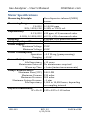
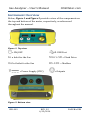
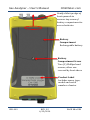
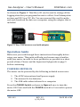
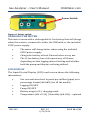
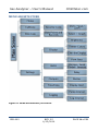
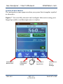
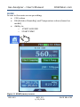
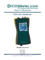
User’s Manual CO2 Gas Analyzer Models Covered CM-1001 CM-1002 CM-1003 Rev. 2.5 6/12/2014 www.co2meter.com Copyright © 2014 CO2 Meter, Inc. All Rights Reserved. Gas Analyzer – User’s Manual CO2Meter.com Save meter information for future reference! Model Number: Serial Number: Purchase Date: USR-003 REV. 2.5 6/12/2014 PAGE 2 of 39 Gas Analyzer – User’s Manual CO2Meter.com Table of Contents WELCOME! ....................................................................................................................4 IMPORTANT SAFEGUARDS .....................................................................................5 METER SPECIFICATIONS ..........................................................................................6 PACKAGE CONTENTS .................................................................................................7 INSTRUMENT OVERVIEW ........................................................................................8 OPERATION GUIDE ................................................................................................. 13 POWERING METER ON ......................................................................................................... 13 CHARGING THE METER ......................................................................................................... 14 LCD DISPLAY.......................................................................................................................... 14 TOUCHSCREEN FUNCTIONS ................................................................................. 15 MENU ARCHITECTURE .......................................................................................................... 16 NAVIGATION MENU ............................................................................................................... 17 HOME ..................................................................................................................................... 18 CALIBRATE.......................................................................................................................... 19 DATA LOGS.............................................................................................................................. 23 SETTINGS ............................................................................................................................. 25 DISPLAY Settings ...........................................................................................................26 OUTPUTS Settings .........................................................................................................27 TIME/DATE Settings ....................................................................................................31 LOGGING Settings ..........................................................................................................32 OPERATION (PUMP ONLY) ................................................................................... 33 TROUBLESHOOTING GUIDE................................................................................. 35 SUPPORT .................................................................................................................... 36 WARRANTY................................................................................................................ 36 RETURNS .................................................................................................................... 37 LIABILITY ................................................................................................................... 38 CONTACT US .............................................................................................................. 38 USR-003 REV. 2.5 6/12/2014 PAGE 3 of 39 Gas Analyzer – User’s Manual CO2Meter.com Welcome! Thank you for purchasing our meter. This portable meter allows you to measure carbon dioxide in inaccessible areas with a built-in battery-operated micro pump. Inside the meter is a battery-operated micro-pump connected to two tubing ports on the side of the meter. When the meter is turned ON, the pump draws gas from one tube port and expels it from the other. By connecting tubing to the inlet, you can remotely sample gas. By connecting tubing to both ports, you can create a closed-loop system and return the gas back to the original container. This makes the meter perfect for measuring potentially dangerous high concentrations of CO2 in biological applications. The meter comes in several models, each with different CO2 levels: 1%, 30% and 100% CO2. All models include a data cable for optional tethered data. The 3.2” touch screen display gives easy access to programming, colors, calibration, logging mode, outputs, etc. Please take some time to read through this manual in order to become familiar with your meter. Make sure to visit our website regularly to find more information about this product. Please also pay special attention to the important safeguards shown on the pages ahead. USR-003 REV. 2.5 6/12/2014 PAGE 4 of 39 Gas Analyzer – User’s Manual CO2Meter.com Important Safeguards To reduce the risk of fire, electrical shock and/or injury to persons, basic safety precautions should always be followed when using electrical appliances, including the following: 1. 2. 3. 4. 5. 6. 7. 8. 9. 10. READ ALL INSTRUCTIONS BEFORE USING THIS METER! Charge rechargeable meters for at least 8 hours before use. The rechargeable meter contains a lithium polymer (LiIon) battery. Do not expose the meter to extreme heat or cold. The Li-Ion battery is not user-replaceable. Please don’t attempt to open the meter and replace the battery. Use only the included power supply to operate the meter. Make sure that the tubes are securely attached to the device when sampling in a closed environment. Do not operate with an obstructed sample path. Do not allow the meter to be exposed to water. Do not operate the device with the enclosure opened. Do not operate the meter if it is malfunctioning. SAVE THESE INSTRUCTIONS! USR-003 REV. 2.5 6/12/2014 PAGE 5 of 39 Gas Analyzer – User’s Manual CO2Meter.com Meter Specifications Measuring Principle: Non-dispersive infrared (NDIR) sensor Measuring Range: 1% CO2 30%, 100% CO2 Repeatability: 0-1% CO2 0-30%, 0-100% CO2 Accuracy: Air Quality Aspect Measured: Power Supply: Maximum Voltage Minimum Voltage Power Consumption: Operation Charging Sensor Ratings: Life Expectancy Maintenance Interval Warm-up Time Pump Characteristics: Maximum Flow (STP) Maximum Vacuum Maximum Pressure Maximum System Pressure Life Expectancy 0-10,000 ppm 0-30% or 100% vol. ±20 ppm, ±1% measured value ±0.1%, ±2% of measured value ±30ppm, ±5% measured value CO2 concentration 9VDC 6VDC ~0.5 W avg. (pump running) ~15 W >15 years No maintenance required <1 min (instant measurements) 0.40 LPM 150 mbar 500 mbar ~1 atm 1,000 to 10,000 hours, depending on sampling interval Physical Dimensions: W x H x D 3.85 x 8.25 x 1.65 inches USR-003 REV. 2.5 6/12/2014 PAGE 6 of 39 Gas Analyzer – User’s Manual CO2Meter.com Package Contents Please verify that your package contains the following items before using the meter: 1. 2. 3. 4. 5. 6. 7. 8. 9. 10. 11. 12. 13. 14. 15. (1) User manual (1) Meter (1) Rubber Boot (1) 6-foot USB Cable (1) Li-Ion Battery (1) 8-pin Quick Connector (1) RS-485 Jack Connector (1) 6VDC International Power supply (1) 10-foot length 1/8” tubing (2) 1/8” Barb tubing bulkhead fitting (2) 1/8” Barb 10-32 fittings (2) Particle Filter (CM-0118) (2) Hydrophobic Filter (CM-0117) (2) Moisture Trap (CM-0112) (1) 2GB Micro SD Card with Adapter Optional Accessories Nafion Tubing for Gas Sampling sensor (TUB-0003) Extreme Replacement filter (CM-0103-F) Hypodermic Needle Kit (CM-0175) Note: Please contact our technical support staff for more details about these accessories. USR-003 REV. 2.5 6/12/2014 PAGE 7 of 39 Gas Analyzer – User’s Manual CO2Meter.com Instrument Overview Below, Figure 1 and Figure 2 provide a view of the components on the top and bottom of the meter, respectively, as referenced throughout the manual. Figure 1: Top view. = ON/OFF = USB Port In = Inlet for the Gas Micro SD = Flash Drive Out= Outlet for the Gas RS-485 = Modbus = Power Supply (VDC) = Outputs Figure 2: Bottom view. USR-003 REV. 2.5 6/12/2014 PAGE 8 of 39 Gas Analyzer – User’s Manual CO2Meter.com Power Switch Press once for ON, press & hold for 5 seconds for OFF Barb Fittings Connect to sampling system for closed loop sampling Display Full color touch screen shows CO2 levels and other information Non Removable Protective Boot Protects meter from impact USR-003 REV. 2.5 6/12/2014 PAGE 9 of 39 Gas Analyzer – User’s Manual CO2Meter.com Gently slide top edge of boot upwards to uncover top screw of battery compartment to access batteries. Battery Compartment Rechargeable battery Battery Compartment Screw Two (2) Phillips head screws, other one covered by boot above Product Label Includes name, type, model and serial number of meter USR-003 REV. 2.5 6/12/2014 PAGE 10 of 39 Gas Analyzer – User’s Manual CO2Meter.com Power Source The meter is powered by Li-Ion Rechargeable 3.7v 60000 mhA battery but can also be powered by the included 6VDC International wall power supply. Accessories Included As shown in Figure 3. This jack provides an integrated RS485 converter and terminates to wire ends. Only three conductors D1, D0 and Common are used. This cables allows a host PC (with suitable software) to communicate with multiple RS485 devices on the cable. FTDI-USB to Modbus RJ45 Wiring RJ45 PIN FTDI USB Color Cat-5 Color Terminal 4 Yellow Blue RS485 A 5 Orange White/Blue RS485 B 8 Black Brown GND Table 1- RS-485 wiring USR-003 REV. 2.5 6/12/2014 PAGE 11 of 39 Gas Analyzer – User’s Manual CO2Meter.com Figure 3: One RS-485 jack connector (Modbus protocol communications) As shown in Figure 4. This quick connector allow you to use the Relay 2 option on the unit to control a fan, solenoid valve or any device that work with 30 VDC and 1 A. Also provide the connections fo futures accessories. Figure 4: One 8-pin quick connector USR-003 REV. 2.5 6/12/2014 PAGE 12 of 39 Gas Analyzer – User’s Manual CO2Meter.com As shown in Figure 5. This Micro SD card is used to storage all the Logging data that you program the unit to collect. It will stamp date an time and CO2 in a CSV. file. You can removed the card from the unit and download the data on a computer using the adapter that is included. Figure 5: One 2-GB MicroSD card with adapter Operation Guide Make sure you read through these instructions thoroughly before using your meter. This guide will help you become more familiar with your meter in order to be as productive as possible in a short period of time. Please read the Important Safeguards on page 5 before continuing. POWERING METER ON The meter can be powered by the following included accessories: 1. The 6VDC international wall power supply 2. The internal Li-Ion batteries 3. The USB cable when tethered to a computer Press the POWER Switch as shown in Figure 6 once to turn the meter ON. Press and hold the POWER switch for 5 seconds to power the meter OFF. USR-003 REV. 2.5 6/12/2014 PAGE 13 of 39 Gas Analyzer – User’s Manual CO2Meter.com Power Switch Figure 6: Power switch. CHARGING THE METER This meter comes with a rechargeable Li-Ion battery that will charge when the meter is connected to either the USB cable or the included 6VDC power supply. • • • The meter will charge faster when using the included 6VDC power supply. Charge the battery at least 8 hours before every use. The Li-Ion battery has a life expectancy of 8 hours, depending on data logging interval setting and whether both the pump and display are being utilized. LCD DISPLAY The Liquid Crystal Display (LCD) touch screen shows the following information: • • • • • USR-003 Gas concentration level in parts-per-million (ppm) or in percentage format (##.##%) for all the models Logging ON/OFF Pump ON/OFF Battery usage in % / charging mode Temperature (##. # C/F) / Humidity (##. #%) – optional REV. 2.5 6/12/2014 PAGE 14 of 39 Gas Analyzer – User’s Manual CO2Meter.com Touchscreen Functions Use your finger or stylus pen to operate the resistive touchscreen display as shown in Figure 7. NOTE: Do not use sharp objects to operate screen. Bluetooth (optional)/ Time /Battery Gage Gas Reading’s ppm / % Initiate or stop logging cycle Initiate or stop pump cycle Display graphically the values Barometric Pressure Indicator / Temperature & Humidity Indicator (optional) Navigation Menu Figure 7: Screen functions. USR-003 REV. 2.5 6/12/2014 PAGE 15 of 39 Gas Analyzer – User’s Manual CO2Meter.com MENU ARCHITECTURE Figure 8: Menu architecture/structure. USR-003 REV. 2.5 6/12/2014 PAGE 16 of 39 Gas Analyzer – User’s Manual CO2Meter.com NAVIGATION MENU The navigation menu appears when you press the triangular symbol as shown in Figure 7. You can fully interact and configure this meter using your fingertips (with or without gloves) or a stylus. Takes you to Main Screen USR-003 Takes you to Calibration Screen Takes you to Logs Screen REV. 2.5 6/12/2014 Takes you to Device Settings PAGE 17 of 39 Gas Analyzer – User’s Manual CO2Meter.com HOME Access to the main screen providing: CO2 values RH (Relative Humidity) and Temperature values (based on model) Ability to: o START LOGGING o START PUMP Figure 9: HOME (main) screen. USR-003 REV. 2.5 6/12/2014 PAGE 18 of 39 Gas Analyzer – User’s Manual CO2Meter.com CALIBRATE In order to access the CALIBRATION screen shown in Figure 10, a passcode is required. When prompted, enter passcode “1234” on the key pad. The calibration screen allows you to access various calibration options and the sensor information tab. Calibration with 100% N2 (nitrogen) Calibration with fresh air at 400 ppm Calibration with CO2 or other known gas Figure 10: CALIBRATE screen. USR-003 REV. 2.5 6/12/2014 PAGE 19 of 39 Gas Analyzer – User’s Manual CO2Meter.com Calibration The calibration process varies depending on the type of meter. All meters are factory-calibrated with multiple reference points of gas, and have been verified to be accurate within their specific functionality before shipment. However, if the meter is severely jolted or otherwise mechanically disturbed, the sensor can drift requiring recalibration. Procedure To calibrate the meter, follow these steps: 1. Turn ON the meter and wait the warm up period (1-3 min) 2. On the Main Screen turn ON the Pump. 3. Expose the meter to ambient air (assumed to be at ~400ppm) or connect it to a calibration gas bottle/cylinder (100% nitrogen or Argon) with the appropriate demand regulator or flow regulator. 4. Wait 25 seconds to collect a sample. Write down this value as the “before” value. 5. Click the “Calibrate” button after selecting your calibration gas. 6. Wait 25 seconds again. The meter will take a sample and use this data to adjust zero values. The displayed measurement will show the new calibration value (0 or 400ppm, depending on the method used). 7. Disconnect the calibration gas and wait 25 seconds. All displayed data will now be based on the new calibration value. 8. Repeat this procedure if the sensor is still operating outside of its specified range or if readings vary greatly (typically indicates that the calibration process was unsuccessful). USR-003 REV. 2.5 6/12/2014 PAGE 20 of 39 Gas Analyzer – User’s Manual CO2Meter.com 0-1% or 0-30% Sample Draw Meter Calibration can be performed using either the “Calibrate to Zero” or the “FA Calibration” option, if using 0% CO2 calibration gas (typically nitrogen, Argon, etc.) or a fresh source of air (assumed to be ~400ppm), respectively. 0-100% Sampling Meter with or without Data Logging The 0-100% meters do not include the “FA Calibration” option due to the CO2 range they measure. To ensure the highest accuracy, we recommend calibrating these meters with calibration gas 100% Nitrogen for ZERO and a knowing calibrate CO2 gas, close to the concentration being measured. Alternatively, a 0% CO2 or ambient calibration can be performed. To perform a calibration, power your meter using the wall adapter and either expose it to ambient air or feed it with your calibration gas. USR-003 REV. 2.5 6/12/2014 PAGE 21 of 39 Gas Analyzer – User’s Manual CO2Meter.com Info The Info tab allows you to change the MODBUS address of the unit to get RS-485 communication. Also is where the meter information is located. Meter ID, Sensor Model and Sensor ID. I2C/MODBUS Address Settings Handheld Meter Serial # Sensor Type or Name Sensor Serial # Figure 11: Address for the MODBUS USR-003 REV. 2.5 6/12/2014 PAGE 22 of 39 Gas Analyzer – User’s Manual CO2Meter.com DATA LOGS Access logs, display data graphically and view the data storage of the meter. Graph from selected Logs Records list Figure 12: DATA LOGS screen. USR-003 REV. 2.5 6/12/2014 PAGE 23 of 39 Gas Analyzer – User’s Manual CO2Meter.com Data Storage All models feature a 2GB memory micro SD card capable of storing data. This will allow you to simultaneously read and store data of CO2 concentration levels. Charge the meter 8 hours before any operation. The logging period and real-time clock will need to be set under the “Settings” menu as shown in Figure 13. The micro SD card has the capacity to store up to 12 million data points. This micro SD card can be replaced with a compatible card with larger capacity if desired. The supplied micro SD card comes with its adapter to ensure compatibility with your computer and facilitate the download process. USR-003 REV. 2.5 6/12/2014 PAGE 24 of 39 Gas Analyzer – User’s Manual CO2Meter.com SETTINGS Allows access to parameters, options, outputs, communications, and date/time settings for changes or reprogramming. Firmware version Display settings Figure 13: SETTINGS screen. Scroll and select as needed from the list. USR-003 REV. 2.5 6/12/2014 PAGE 25 of 39 Gas Analyzer – User’s Manual CO2Meter.com DISPLAY Settings From this screen, the brightness level and color theme (3 available) can be changed on the meter. In addition, a Screen Timeout can be activated to save power. NOTE: This setting will not affect the meter’s functionality but is important to indicate that it will affect the battery life depending on how the parameter is set. Figure 14: Display settings screen. Scroll horizontally to set brightness. USR-003 REV. 2.5 6/12/2014 PAGE 26 of 39 Gas Analyzer – User’s Manual CO2Meter.com OUTPUTS Settings Change the parameters on the relays and other alerts. Figure 15: Output settings screen – RELAY1 tab. RELAY 1 controls an audible alarm built into the meter, it can be programmed to be activated by the CO2 readings, Temperature and Relative Humidity as well as other sensors attached to the meter. NOTE: Temp/RH probe is optional. USR-003 REV. 2.5 6/12/2014 PAGE 27 of 39 Gas Analyzer – User’s Manual CO2Meter.com Figure 16: Output settings screen – RELAY2 tab. RELAY 2 is available as an output located on pin #8 of the female connector. The meter includes a male connector that enables you to use the relay terminal (NC, NO, COM) to control any other device. The diagram below will help you locate the terminals for the relay. USR-003 REV. 2.5 6/12/2014 PAGE 28 of 39 Gas Analyzer – User’s Manual USR-003 REV. 2.5 6/12/2014 CO2Meter.com PAGE 29 of 39 Gas Analyzer – User’s Manual CO2Meter.com Figure 17: Output settings screen – ALERT tab. The ALERT is an additional function of the meter which when programmed; the main screen will change colors according to the CO2 values that are pre-programmed, as shown below. USR-003 REV. 2.5 6/12/2014 PAGE 30 of 39 Gas Analyzer – User’s Manual CO2Meter.com TIME/DATE Settings Allows you to change the date and time on the meter for more accurate reference on the logs. The default time of your meter may vary depending on your location. NOTE: Please review these settings before using the meter. Figure 18: TIME/DATE settings screen. USR-003 REV. 2.5 6/12/2014 PAGE 31 of 39 Gas Analyzer – User’s Manual CO2Meter.com LOGGING Settings Allows you to configure the logging interval, specify the default file name, and turn the PRESSURE COMPENSATION feature ON/OFF, as shown on Figure 19 below This will enable collection of data at a specified logging interval. Figure 20 shows the PUMP tab screen, which allows you to set the PUMP TIMER if desired. If the pump timer is not configured, the pump will run continuously until user stops it using the controls on the main screen. NOTE: Synchronize the logging interval of the meter so that it takes place while the pump is running (inside the pump interval). Figure 19: LOGGING settings screen – LOG tab. USR-003 REV. 2.5 6/12/2014 PAGE 32 of 39 Gas Analyzer – User’s Manual CO2Meter.com Figure 20: LOGGING settings screen - PUMP tab. Operation (Pump Only) In order to use the meter, sampling hoses must be attached to the inlet and outlet fittings on the top of the meter as shown on Figure 1. The pump will draw air from the inlet in a vacuum configuration, push it through the sensing chamber, and exhaust the air out through the outlet. USR-003 REV. 2.5 6/12/2014 PAGE 33 of 39 Gas Analyzer – User’s Manual CO2Meter.com Closed Loop Operation Figure 21: Closed loop operation setup. Open Loop Operation with Environmental Exhaust Figure 22: Open loop sampling setup. Utilization of the included humidity/particulate filter is recommended for closed or open loop sampling to ensure sensing chamber and pump baffle remains clear and to prevent corrosion. USR-003 REV. 2.5 6/12/2014 PAGE 34 of 39 Gas Analyzer – User’s Manual CO2Meter.com Troubleshooting Guide Symptom / Issue Possible Cause / Solution Meter/Sensor is not recognized by the Handheld The meter’s batteries might be depleted. Replace the batteries with fresh ones, or if applicable, connect the device to the included power supply or call support. Confirm the power adapter is connected to the meter properly. Ensure proper power supply and the adapter connected has the appropriate voltage. If using batteries, confirm they are not depleted. Confirm the SD card is installed correctly. Memory is full. Check the air flow channels to make sure they are not obstructed. Make sure the meter is in maximum or minimum mode. The power adapter output voltage is inappropriate. Please use the included power supply. Meter doesn’t power ON The meter is not logging Slow response Reading doesn’t change Battery lightning bolt icon not shown when charging USR-003 REV. 2.5 6/12/2014 PAGE 35 of 39 Gas Analyzer – User’s Manual CO2Meter.com Support The quickest way to obtain technical support is via email. Please send all support inquires to [email protected]. Please include a clear, concise definition of the problem and any relevant troubleshooting information or steps taken so far, so we can duplicate the problem and quickly respond to your inquiry. Warranty This meter comes with a 1YEAR (warranty period) limited manufacturer’s warranty, starting from the date the meter was shipped to the buyer. During this period of time, CO2Meter.com warrants our products to be free from defects in materials and workmanship when used for their intended purpose and agrees to fix or replace (at our discretion) any part or product that fails under normal use. To take advantage of this warranty, the product must be returned to CO2Meter.com at your expense. If, after examination, we determine the product is defective, we will repair or replace it at no additional cost to you. This warranty does not cover any products that have been subjected to misuse, neglect, accident, modifications or repairs by you or by a third party. No employee or reseller of CO2Meter.com’s products may alter this warranty verbally or in writing. USR-003 REV. 2.5 6/12/2014 PAGE 36 of 39 Gas Analyzer – User’s Manual CO2Meter.com Returns If the product fails under normal use it may be returned. An RMA (Return Material Authorization) number is required to process any return no matter the reason. To obtain an RMA number, please send an email to: [email protected] When requesting an RMA number, please provide the reason for return and original order number. Once you have an authorization code you may complete your return processing by visiting www.co2metersupport.com/rma. When asked, enter the authorization code you were provided. Please use the original packaging (if available) when returning the meter to CO2Meter. Include the provided RMA number on the outside of the box, preferably on the shipping label. Secure the meter inside the package properly to prevent any damage during transit. Ship your meter to the address listed on your RMA paperwork. CO2Meter.com will not, under any circumstances, be responsible or issue refunds for any shipment expenses. NOTE: For items returned during the warranty period, return shipping will not be charged. Meters that are have failed due to improper use, damaged, abuse, or are out of warranty period will be examined and an estimate of repair/replacement will be provided to you. USR-003 REV. 2.5 6/12/2014 PAGE 37 of 39 Gas Analyzer – User’s Manual CO2Meter.com Liability All liabilities under this agreement shall be limited to the actual cost of the product paid to CO2Meter.com. In no event shall CO2Meter.com be liable for any incidental or consequential damages, lost profits, loss of time, lost sales or loss or damage to data, injury to person or personal property or any other indirect damages as the result of use of our products. Contact Us We are here to help! For information or technical support, please contact us. [email protected] (386) 256-4910 ( Technical Support) (386) 872-7665 (Sales) www.co2meter.com Address: CO2Meter 131 Business Center Ormond Beach, FL 32174 USA USR-003 REV. 2.5 6/12/2014 PAGE 38 of 39 Gas Analyzer – User’s Manual CO2Meter.com NOTES: USR-003 REV. 2.5 6/12/2014 PAGE 39 of 39