1
Software
PHOTOMOD 4.4
Scanner Images Processing
USER
MANUAL
Racurs, Moscow, 2009
PHOTOMOD 4.4
1.
Space imagery processing in PHOTOMOD software system .................................................. 3
2.
SPOT Monoblock processing workflow ..................................................................................... 3
2.1
Launch PHOTOMOD Montage Desktop................................................................................ 3
2.2
Create PHOTOMOD project .................................................................................................. 4
2.2.1 Set PHOTOMOD project parameters ................................................................................ 4
2.2.2 Specify the PHOTOMOD project reference system .......................................................... 5
2.2.3 Finalize the PHOTOMOD project parameters setup process ........................................... 6
2.3
Input images into Monoblock project ..................................................................................... 6
2.3.1 Create strip (or strips if needed) ........................................................................................ 6
2.3.2 Add images into the strip ................................................................................................... 7
3.
2.4
Phototriangulation stage ...................................................................................................... 11
2.5
Block adjustment.................................................................................................................. 15
2.6
Orthomosaic creation........................................................................................................... 18
Processing of IKONOS stereopair ............................................................................................ 22
3.1
Project creation in PHOTOMOD .......................................................................................... 22
3.2
Input images into Stereoblock project.................................................................................. 22
3.2.1 Images adjustment .......................................................................................................... 24
3.3
Start of phototriangulation.................................................................................................... 30
3.4
Ground control, check and tie points measurement ............................................................ 31
3.5
Block adjustment and pass to processing stage.................................................................. 34
3.6
Creation of orthomosaic for IKONOS stereopair ................................................................. 38
© 2009
2
Scanner projects processing
July 25, 2009
1. Space imagery processing in PHOTOMOD software system
Digital photogrammetric system PHOTOMOD allows to process images acquired by space
scanners and to produce both cartographic and other output products.
PHOTOMOD system includes special type of projects intended for space imagery processing
– Scanner survey projects. If initial images make up a valid stereopair you should select
Stereoblock subtype of the project to be created. If there is no images overlap or the overlap
is not good enough to perform stereo processing, select Monoblock subtype. Single space
images are processed in Monoblock subtype projects either.
The Manual is aimed to demonstrate the workflow of both scanner survey projects subtypes
in general: SPOT 5 set of images as Monoblock project (see the chapter 2 SPOT
Monoblock processing workflow), and IKONOS stereopair as Stereoblock project (see the
chapter 3 Processing of IKONOS stereopair).
Details of space images formats and their processing in PHOTOMOD are described also in
Overview and PHOTOMOD Montage Desktop User manuals.
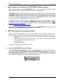
2. SPOT Monoblock processing workflow
Block of space images without stereo overlap (SPOT 5 set of images is shown as an
example here) as well as single scanner image processing consists of several main stages:
project creation (which includes reference system specification and images
addition);
points measurement (ground control and check points coordinates specification
and points measurement on the images);
block adjustment;
orthomosaic creation.
The step-by-step instructions are given below.
2.1
Launch PHOTOMOD Montage Desktop
Start PHOTOMOD System Monitor first (from standard Start menu of OS Windows using
command Programs | PHOTOMOD | Utility | PHOTOMOD System Monitor). Then launch
PHOTOMOD Montage Desktop using either double click on PHOTOMOD System Monitor
icon in Windows system tray or standard Windows Start menu.
3
RACURS Co., Ul. Yaroslavskaya, 13-A, office 15, 129366, Moscow, Russia
PHOTOMOD 4.4
2.2
Create PHOTOMOD project
Push the Create button in the window appeared to start new PHOTOMOD project creation.
2.2.1 Set PHOTOMOD project parameters
In the New project window specify some project name (mandatory) and project description
(optionally). Select the project type. It should be Scanner survey | Monoblock in this case.
The word “Monoblock” means that the images overlaps do not constitute stereopairs. Select
this project type both for single SPOT image or several ones without stereo overlap.
© 2009
4
Scanner projects processing
July 25, 2009
2.2.2 Specify the PHOTOMOD project reference system
To complete the project creation, select coordinate system by pushing the Select button. The
reference systems are stored in databases. You can install several databases into each of
PHOTOMOD data storages; moreover, you can use several storages simultaneously. So you
should select the reference systems database first (select the database and push the Open
button).
Then select the appropriate reference system from the list. Use search operation to find the
reference system by its name.
It should be noted that currently PHOTOMOD project cannot use latitude-longitude reference
systems for the workflow. So, if necessary, convert the source data (GCP coordinates and
DEM) into some projected reference system (using PHOTOMOD), then implement the
workflow, and finally create the output orthoimagery with respect to the latitude-longitude
system.
Please remember also that the “Cartesian Left”, “Cartesian Right”, “Local Left”, “Local Right”
systems cannot be used with the pushbroom imagery, because the relation between the
5
RACURS Co., Ul. Yaroslavskaya, 13-A, office 15, 129366, Moscow, Russia
PHOTOMOD 4.4
systems and global frames is unknown (but it is necessary for involving the imagery
metadata into adjustment process). See PHOTOMOD Mosaic User Manual.
When the appropriate reference system is selected (or created), push OK to finalize the
reference system specification.
Refer to PHOTOMOD Montage Desktop User Manual for more details on coordinate
systems creation or selection.
2.2.3 Finalize the PHOTOMOD project parameters setup process
When project name, project type and project reference system are specified in the New
project window, push OK to proceed.
In the dialog appeared select the PHOTOMOD storage for your project if you work with
several PHOTOMOD storages.
2.3
Input images into Monoblock project
2.3.1 Create strip (or strips if needed)
Any image of PHOTOMOD project should be placed into some strip. The meaning of the
term “strip” is not proper for pushbroom block (contrary to aerial block). In the case of
pushbroom monoblock project the only way of using strips is that PHOTOMOD supposes
that strip is oriented “horizontally”, so it is reasonable to place into the same strip images
which have side (but not top and bottom) overlaps.
© 2009
6
Scanner projects processing
July 25, 2009
So before an image addition you should create or select strip and then place the image into
(Add strip) on the Block forming toolbar. If the
it. To create the strip, push the button
toolbar is not visible, turn it on using PHOTOMOD Montage Desktop main menu (Windows
| Toolbars | Block forming).
Then specify the strip properties: input the strip name. There is no need to change the strip
orientation.
2.3.2 Add images into the strip
When a new strip has been created or selected (which can already contain some images),
you can add one or several images into it.
7
RACURS Co., Ul. Yaroslavskaya, 13-A, office 15, 129366, Moscow, Russia
PHOTOMOD 4.4
Push the button
(Add images) on Block forming toolbox to call the dialogue of
images adding (make sure that the marker is inside the strip frame in 2D window).
The dialog contains two tabs.
© 2009
8
Scanner projects processing
July 25, 2009
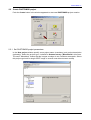
The left tab Select folder is used to select folder that contains the data while the right tab
Add images are used to add imagery into the project.
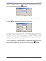
The dialog conceptually based on automatic imagery recognition. When user changes from
Select folder tab to Add images tab, the image recognition procedure is started. It searches
for imagery metadata and reads it. So it is not allowed to rename or move files of the source
imagery product.
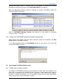
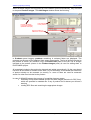
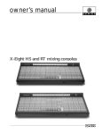
The results of the analysis are shown on the picture below.
The window shows the imagery products recognized, the files, which comprise the product
and the images the product includes.
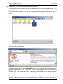
The Preprocessing button opens a window intended for preliminary radiometric processing
of the images; it is necessary if the input imagery have dynamic range more than eight bits
per sample. More details on radiometric processing of the images see in the chapter 3.2.1
Images adjustment.
The field Name in Parameters panel specifies the image name in the project (it may differ
from the image filename or product ID). The name must have length of 2-32 symbols. Push
the button Add to add the image to project
You can return to the Add images tab, select new folder and to add images from it too.
9
RACURS Co., Ul. Yaroslavskaya, 13-A, office 15, 129366, Moscow, Russia
PHOTOMOD 4.4
Product containing
in the folder selected
Files included
to the product
Images to be added to the project
Names of the images added previously are listed in the panel above the buttons.
Push the OK button to close the window saving changes.
You will return to the PHOTOMOD Montage Desktop window; the images will be written into
PHOTOMOD Storage; the source imagery data will not be used anymore.
© 2009
10
Scanner projects processing
July 25, 2009
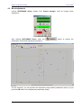
Then in PHOTOMOD Montage Desktop window add new strips here and add images into
them.
Then push the button
in the Project manager window to get from Block forming to
Aerial triangulation stage.
2.4
Phototriangulation stage
The stage is called Aerial triangulation but nevertheless it regards to space pushbroom
imagery too. On the stage user should collect point’s data: input geodetic coordinates of
ground control and check points and measure on the images ground control as well as tie
points. Run PHOTOMOD AT module to perform the operations.
AT interface is based on the set of tabs, which are used in left-to-right order.
11
RACURS Co., Ul. Yaroslavskaya, 13-A, office 15, 129366, Moscow, Russia
PHOTOMOD 4.4
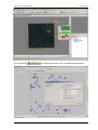
The tab Measuring GC points is used to specify the ground points geodetic coordinates and
to measure the ground points on the images.
to call the window for ground points geodetic
Use the button
coordinates input.
(Import) button
You can load the ground points coordinates from the text file using the
or input it manually immediately in the table. The coordinates must be given with respect to
the project reference system specified above (see the chapter 2.2.2 Specify the
PHOTOMOD project reference system). If coordinates of all the points have the same
accuracy, all the weights should be set to be unity.
So, you should fill the catalog of ground control and check points geodetic coordinates. Then
close the window using the button
procedure by pushing the button
and start measuring points on images. Run the
(Measure point).
In the window opened select a point from the list in the window bottom, select the appropriate
image using the button
(Select image) and find the point on the image (referring to
overview image on the left and lens image on the right). Then push the button
(Measure) to place the point in the current marker position.
© 2009
12
Scanner projects processing
July 25, 2009
You should measure each point on the appropriate single image in the window.
To measure tie points and to transmit already measured ground points to other images use
the tab Measuring tie points.
13
RACURS Co., Ul. Yaroslavskaya, 13-A, office 15, 129366, Moscow, Russia
PHOTOMOD 4.4
You should select two images for the ties measurement procedure. When a strip is selected
in the appropriate left column, the images of the strip are shown in the right column. Push the
(Measure points) to measure points that ties the
button
selected images.
If the images selected belong to the same strip (side-to-side overlap), the window is arranged
horizontally; if they belong to different strips (bottom-to-top overlap), the window is arranged
vertically.
You can add tie point or transmit already measured ground control, check or tie point with
correlation (using the icon
algorithm (using the icon
(Add with correlation)) or manually without correlation
(Add without correlation)).
You should measure several tie points in each overlap and transmit ground points to all the
images the point belongs. You can change the images using buttons on the top of the
window
,
(next/previous image of the strip).
Refer to the PHOTOMOD AT User Manual to see more about ground control and tie points
measurement in PHOTOMOD.
When all the points are measured, close the window and leave PHOTOMOD AT module.
You will return to PHOTOMOD Montage Desktop. Get to the next stage Block adjustment
using the button
© 2009
in the Project Manager window.
14
Scanner projects processing
2.5
July 25, 2009
Block adjustment
Launch PHOTOMOD Solver module from Project manager used for images block
adjustment.
After starting PHOTOMOD Solver, push the
parameters of the block adjustment procedure.
button to specify the
For the simplicity, you can perform the adjustment using default parameters values; so just
push the OK button in the adjustment parameters dialog.
15
RACURS Co., Ul. Yaroslavskaya, 13-A, office 15, 129366, Moscow, Russia
PHOTOMOD 4.4
Then push the
button to start the adjustment process.
You should check the adjustment results: push the
adjustment report.
Then save the adjustment results – push the button
© 2009
button to view the
.
16
Scanner projects processing
July 25, 2009
See more details on project adjustment in PHOTOMOD Solver User Manual.
When the adjustment is completed, close PHOTOMOD Solver and get to the next stage in
PHOTOMOD Montage Desktop.
17
RACURS Co., Ul. Yaroslavskaya, 13-A, office 15, 129366, Moscow, Russia
PHOTOMOD 4.4
2.6
Orthomosaic creation
Start PHOTOMOD Mosaic to create orthoimagery.
Create new PHOTOMOD Mosaic project (using menu command Project | New):
Specify the PHOTOMOD Mosaic project parameters in the Parameters window (use
Mosaic | Parameters menu command to open it).
The first tab of the dialog is intended to specify the appropriate relief model to be used for
orthomosaic creation. To import your DEM into PHOTOMOD project, select the DEM option
and push the Import button.
© 2009
18
Scanner projects processing
July 25, 2009
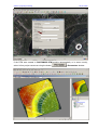
Convert the DEM into the PHOTOMOD project reference system. Using the dialog you can
cut the appropriate part of the DEM if your DEM is much larger than the imagery block; it will
save space on your hard disks.
Then pass to the Orthoimage tab of the mosaic parameters dialog.
19
RACURS Co., Ul. Yaroslavskaya, 13-A, office 15, 129366, Moscow, Russia
PHOTOMOD 4.4
The most important settings are the Cell size (ground sample distance for the output
orthoimage) and reference system for the output orthoimage (the reference system may
differ from the PHOTOMOD project reference system).
You can also select the type of the georeference file here (MapInfo, Arc World,
PHOTOMOD). Then push the OK button to close the mosaic parameters dialog.
To create the orthoimage push the button
© 2009
or use menu command Mosaic | Build!
20
Scanner projects processing
July 25, 2009
Select the appropriate type of the output orthoimage in the window of resulting mosaic file
saving.
21
RACURS Co., Ul. Yaroslavskaya, 13-A, office 15, 129366, Moscow, Russia
PHOTOMOD 4.4
Refer to PHOTOMOD Mosaic User Manual for more details on orthophotos creation in
PHOTOMOD system.
3. Processing of IKONOS stereopair
3.1
Project creation in PHOTOMOD
When creating a project for stereopair of scanner images (in this case, acquired by IKONOS
satellite) select the project type – Scanner survey | Stereoblock. The rest of project
creation procedure is the same as described in the chapter 2.2 Create PHOTOMOD project.
Coordinate system selection for the project to be created is described in the chapter 2.2.2
Specify the PHOTOMOD project reference system.
Note: Reference systems of the following types: “Cartesian” and “Local Curved”
should not be used with IKONOS projects, because the systems are local (arbitrary
positioned and oriented) while Rational Polynomial Coefficients (RPCs) the IKONOS
imagery is supplied with are referenced with respect to global (WGS-84) reference
system
Note: Current version of PHOTOMOD does not support geodetic (latitude-longitude)
reference systems
3.2
Input images into Stereoblock project
After closing the dialogue of new project creation call the toolbar Block forming in
PHOTOMOD Montage Desktop module using menu command Windows | Toolbars |
Block forming, create new strip and add there initial images. See the chapter 2.3 Input
images into project for more details on adding images to the project.
© 2009
22
Scanner projects processing
July 25, 2009
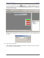
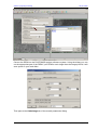
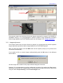
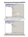
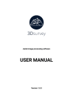
When IKONOS images are recognized by PHOTOMOD system automatically, they are listed
in the panel Product images. The Add images window shows the following.
Product containing
in the folder selected
(IKONOS stereopair)
Files included
to the product
Opens a window on
radiometric correction
Images included
to the selected product
Image name in
PHOTOMOD project
In Products panel imagery products containing in selected folder are displayed. The
products are the sets of files obtained from space data supplier. The list of all files included to
the product is shown (for reference only) in Product files panel to the left. List of images
included to the product (shown in the Product images panel) is used for adding them to
PHOTOMOD project.
All metadata included to the product is detected and added automatically. So the user should
not know all the details of formats of the data, it is just necessary to remember that initial files
of product should not be renamed (or moved), i.e. some of them are used for automatic
search for other files included to the product.
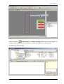
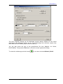
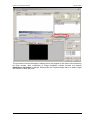
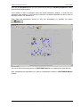
In case of IKONOS imagery the process of recognition has two stages:
searching for file with metadata and for files with images (and also for RPC files),
which are specified in metadata file. If any of product files is absent you will see a
warning
reading RPC files and searching the appropriate images.
23
RACURS Co., Ul. Yaroslavskaya, 13-A, office 15, 129366, Moscow, Russia
PHOTOMOD 4.4
Files with RPC
included to the product
Image preview
after correction
If the source raster has more than 8 bits per sample (acquired for instance, by IKONOS or
QuickBird sensors), it is recommended to perform dynamic range adjustment procedure
before image addition into PHOTOMOD project, see the chapter 3.2.1 Images adjustment.
3.2.1 Images adjustment
If the source raster has more than 8 bits per sample it is recommended to perform dynamic
range adjustment procedure before image addition into PHOTOMOD project.
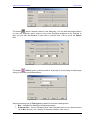
After you select an image, push the Add button and the system prompt you to perform such
conversion automatically.
If you would not like to correct images radiometrically push the No button in the dialogue
shown below:
and the image will be added to the project without histogram correction.
However it is recommended to perform radiometric correction (by pushing the Yes button).
Advanced users could set up parameters of the procedure and start the process themselves
using the button Preprocessing in the Product images field.
© 2009
24
Scanner projects processing
July 25, 2009
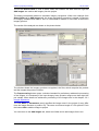
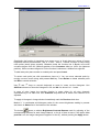
The procedure includes histogram creating which may appear to be rather time-consuming
for large images. After completing of image histogram creation process the window
Radiometric correction is opened. Window title bar contains image name, its width, height
and number of bites per pixel.
25
RACURS Co., Ul. Yaroslavskaya, 13-A, office 15, 129366, Moscow, Russia
PHOTOMOD 4.4
Note. Temporal pyramidal image is created in Temp subfolder in PHOTOMOD
configuration folder (usually in C:\PHOTOMOD.VAR\Temp). That is why you should
have enough room on hard disk, otherwise the pyramid will be not created and image
visualization at 2 and more zoom will be slow
Temporal pyramidal image and histogram used for preprocessing of the image to be added,
could be deleted after closing the Radiometric correction window, if the option Remove
pyramid and histogram after close is on.
In the Radiometric correction window you may change the results of automatic conversion
manually using tools described below.
The following tools are used for image scale management:
•
(duplicated by “*” key) - one step zoom in
•
(duplicated by “/” key) - one step zoom out
•
(duplicated by “Alt-Enter” keys) - fits image to window
•
(duplicated by “Alt-1” keys) - 1:1 zoom (image cell corresponds to screen pixel)
Current ratio between image size and scale is shown in the window
.
For zooming in by zoom box, press Ctrl-Alt keys and draw the box by the mouse. Use
Ctrl-Alt-Shift keys for zooming out by zoom box. For “panning” over the image move a
mouse cursor along with pressed Alt key.
If there is more than 8 bits per channel in the image, the histogram stretching operation is
applied for the whole brightness range, for each channel independently.
© 2009
26
Scanner projects processing
July 25, 2009
Operation of histogram stretching for the whole brightness range for each channel is started
from the window opened by the button
(Channels).
Note. The initial order of channels is setup depending on type of the image to be
added
The button
opens a window used for auto levels setup operation.
The operation includes stretching the histogram of the initial image on the whole brightness
range. Select necessary channel of image (blue, green or red) in Channels field, and apply
the next parameters of histogram stretching to them. The Number of nodes parameter
specifies the number of intervals of intermediate feature, which is used for histogram
stretching. Parameters Trim left and Trim right show a percent of histogram area to be cut
off, and not be considered in the operation.
To view a histogram of the image to be added and to adjust a transfer function used to setup
arbitrary brightness transformation, open a window by pushing the button
27
(Curves).
RACURS Co., Ul. Yaroslavskaya, 13-A, office 15, 129366, Moscow, Russia
PHOTOMOD 4.4
Graphically the function is visualized as a green curve. In X axis there are values of image
brightness before transformation, and in Y axis – after it. Transfer function is setup using
node points (small green squares). Between nodes the function line is Bezier curve with
curvature degree from 0% (leftmost position of the Curvature slider) to 100% (its rightmost
position). When curvature degree is 0% the function is shown as a broken line segment.
To add node point place marker to needed point and press Insert.
To select node point just click somewhere close to it. You can move selected point by
moving a mouse cursor along with pressed Ctrl key. Press Delete to delete selected point
and Esc to cancel selection.
Use "/" and "*" keys on numeric keyboard to zoom in/ zoom out the histogram. Use
Alt-Enter shortcut to show the histogram in full and Alt-1 to show it in 1:1 scale.
In case of color image the transfer function is setup either for all color channels
simultaneously or for each one. Use Channels drop-down list to select color channel to be
adjusted.
To apply all changes in image window immediately mark the Preview check box.
Marker X, Y coordinates and histogram value for the current brightness reading in percent
are shown in Status line in the bottom of the window.
The button
opens a window Brightness-Contrast-Gamma used for adjusting of the
corresponding features for each image channel, or for all of them at once. If the option Live
preview is on, the image changes are applied “on-the-fly”, without pushing the Apply button.
© 2009
28
Scanner projects processing
July 25, 2009
The button
opens a window used for color balancing. You can shift the image balance
to cyan, red, magenta, green, yellow or blue color. Resulting brightness is not changed at
that. You can also shift balance of each color in numeric form –100 to 100 in the Values
field.
The button
(Filters) opens a window used for improving of visual quality of initial image
using it's processing by different filters.
Select processing type in Filter type drop-down list from the following items:
• Blur – intended for dithering of initial image details
• Gaussian blur – kind of smoothing filter, where transfer value is not a linear function
(as in Blur function), but a section of Gaussian function ("bell curve");
29
RACURS Co., Ul. Yaroslavskaya, 13-A, office 15, 129366, Moscow, Russia
PHOTOMOD 4.4
•
•
•
•
Sharpen – allows to highlight and intensify a differences between image's details
Sharpen edges – alike a Sharpen filter but performs filtering only when brightness
differences between details are exceeding some threshold. Suits very well for
identifying and highlighting of objects borders which are homogeneous insight (fields,
for instance), at that inner part of objects remains unchanged
Median – non-linear filter intended mainly for impulse noises filtration (single pixels
with unnatural brightness)
Sobel – non-linear differential filter, which is the first derivative of the initial raster.
Used for acquisition of contour borders on raster image.
To apply all changes in image window immediately mark the Preview check box.
The button
action. The button
10 actions.
(undo) cancels the last action,
(redo) – redoes the last cancelled
cancels all actions performed, and undo-redo operations list depth is
Note. All operations are applied to the current image state
When you get acceptable correction result in the preview window push the button Close and
go back to Adding images dialogue – see the chapter 3.2 Input images into Stereoblock
project.
The procedure is not the only image enhancement/adjustment operation; other modules of
PHOTOMOD system include brightness-contrast-gamma and color balancing procedures;
the Mosaic module has advanced possibilities to adjust radiometry as well.
3.3
Start of phototriangulation
When all the necessary data contained in the current folder are added and specified in the
lower window of the Parameters panel, go back to the Select folder tab to continue the
image addition process or finish it by the button OK.
Images has been added,
push the button to continue
© 2009
30
Scanner projects processing
July 25, 2009
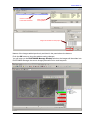
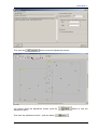
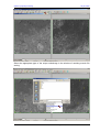
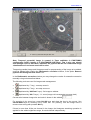
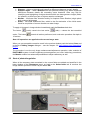
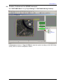
Images of the project are visualized then in the window of PHOTOMOD Montage Desktop
module.
Due along-track stereopair acquisition mode, the IKONOS images are physically upper and
lower to each other; so in case of IKONOS stereopair they are automatically rotated by 90
degrees to be left and right. But if something is wrong, you can rotate images “manually”
using the button
on Block forming toolbar.
The first added image becomes left and the second image is right. User can invert the order
by the button
on Block forming toolbar.
To pass to the next stage, push the button
3.4
in Project manager.
Ground control, check and tie points measurement
The PHOTOMOD AT module (started from Project manager window) is used to perform
point’s measurement on images.
31
RACURS Co., Ul. Yaroslavskaya, 13-A, office 15, 129366, Moscow, Russia
PHOTOMOD 4.4
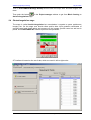
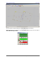
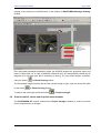
In case of pushbroom imagery processing, use the following PHOTOMOD AT main window
tabs. The tab Measuring GC points allows ground control and check points coordinates
input and their measurement on the images.
© 2009
32
Scanner projects processing
July 25, 2009
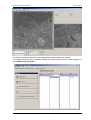
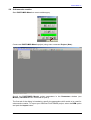
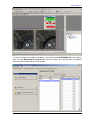
The tab Measuring stereo points is intended for GCPs/CPs and tie points measurement in
stereoscopic mode.
See the chapter 2.4 Phototriangulation stage and PHOTOMOD AT User manual for details
on measurement of GCP and tie points on space images in PHOTOMOD.
33
RACURS Co., Ul. Yaroslavskaya, 13-A, office 15, 129366, Moscow, Russia
PHOTOMOD 4.4
3.5
Block adjustment and pass to processing stage
Push the next
button to pass to block adjustment stage.
Start PHOTOMOD Solver.
© 2009
34
Scanner projects processing
Push the button
35
July 25, 2009
in the opened window to set up adjustment parameters.
RACURS Co., Ul. Yaroslavskaya, 13-A, office 15, 129366, Moscow, Russia
PHOTOMOD 4.4
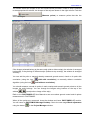
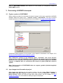
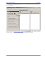
If IKONOS stereopair contains RPC coefficients supplied with the product, they are
considered during adjustment that is shown in the Parameters window on Images tab.
If RPC coefficients are not supplied with the product or the results of adjustment using the
coefficients are poor, you may adjust the projects using Generic algorithm. Select the
appropriate option in this case in the Parameters window on the Images tab:
© 2009
36
Scanner projects processing
July 25, 2009
After that in Parameters panel you can choose the model type: Parallel-perspective or DLT
(direct linear transformation).
If the number of GCP is sufficient, leave the model selected by default – in that case the
algorithms work similarly. If GCP amount is minimal, use default algorithm first and in case of
improper results, use another one.
Then save the adjustment results (if they are acceptable) by pushing the button
.
See more details about adjustment in PHOTOMOD Solver in the appropriate User Manual.
After completing the adjustment you, pass to orthomosaic creation in PHOTOMOD Mosaic
module.
37
RACURS Co., Ul. Yaroslavskaya, 13-A, office 15, 129366, Moscow, Russia
PHOTOMOD 4.4
3.6
Creation of orthomosaic for IKONOS stereopair
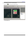
Start PHOTOMOD Mosaic using Project Manager in PHOTOMOD Montage Desktop.
In Parameters window on Type of DTM tab select the option according to the relief model
(DTM), which is used for orthophotos creation.
© 2009
38
Scanner projects processing
July 25, 2009
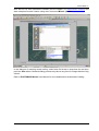
If the DTM was created in PHOTOMOD DTM module (automatically or in stereo mode),
select it from project resources using the button
39
in Parameters window.
RACURS Co., Ul. Yaroslavskaya, 13-A, office 15, 129366, Moscow, Russia
PHOTOMOD 4.4
After that set up other parameters needed (see the chapter 2.6 Orthomosaic creation) and
start orthophoto mosaic creation using menu command Mosaic | Build!.
In the dialogue of resulting mosaic saving, select also file format in drop-down list and then
push the Save button. Mosaic building process may take a long time for images blocks of big
volume.
Refer to PHOTOMOD Mosaic User Manual for more details about orthomosaic building.
© 2009
40