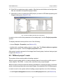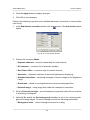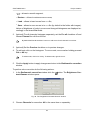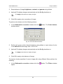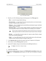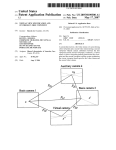
1
Digital Photogrammetric System
Version 6.0.2
USER MANUAL
Project creation
Project creation
PHOTOMOD 6.0.2
Table of Contents
1. Purpose of the document .......................................................................................................... 4
2. Workflow in system ................................................................................................................... 4
3. Creating and choosing active profile .......................................................................................... 4
4. Coordinate Systems ................................................................................................................. 6
4.1. General information ....................................................................................................... 6
4.2. Coordinate systems databases ....................................................................................... 7
4.2.1. International coordinate reference systems database ............................................ 7
4.3. Coordinate reference systems types ............................................................................... 8
5. Project types ............................................................................................................................ 8
5.1. General information ....................................................................................................... 8
5.2. Central projection imagery .............................................................................................. 9
5.3. Satellite scanner imagery ............................................................................................... 9
5.3.1. Processing images algorithms ............................................................................. 9
5.3.2. Formats of satellite scanner images ................................................................... 11
5.3.3. Accuracy of satellite scanner blocks adjustment .................................................. 12
5.3.4. Number of points recommended for adjustment of scanner block ......................... 13
5.4. Airborne Digital Sensor ADS ......................................................................................... 15
5.4.1. Workflow of ADS processing .............................................................................. 15
5.4.2. Preprocessing ADS data ................................................................................... 16
5.4.3. Preparing ADS data in the system ...................................................................... 18
5.4.4. Loading ADS images ......................................................................................... 20
5.4.5. Processing ADS project ..................................................................................... 24
5.5. VisionMap A3 imagery ................................................................................................. 25
5.5.1. VisionMap project processing ............................................................................ 25
5.5.2. VisionMap A3 SLF ............................................................................................ 26
5.5.3. VisionMap A3 (central projection) ....................................................................... 27
6. Project creation ...................................................................................................................... 29
6.1. Creating new project .................................................................................................... 29
6.2. “Without project” mode ................................................................................................. 31
7. Images block forming .............................................................................................................. 32
7.1. The “Block” menu ........................................................................................................ 32
7.2. The “Block editor” window ............................................................................................ 34
7.3. Adding strips ............................................................................................................... 36
7.4. Adding images ............................................................................................................. 37
7.4.1. Images formats ................................................................................................. 37
7.4.2. Adding images from files ................................................................................... 38
7.4.3. Adding images from resources ........................................................................... 44
7.5. Adding scanner images ................................................................................................ 46
7.5.1. Adding scanner images ..................................................................................... 46
7.5.2. Detailed properties of adding images .................................................................. 51
7.5.3. Parameters of images loading ............................................................................ 54
7.6. Image properties .......................................................................................................... 56
7.7. Radiometric correction ................................................................................................. 57
7.8. Editing images block .................................................................................................... 67
7.8.1. Splitting into strips ............................................................................................. 67
7.8.2. Renaming strips ................................................................................................ 69
7.8.3. Deleting images selectively ................................................................................ 70
8. Project management window ................................................................................................... 71
8.1. Project menu ............................................................................................................... 71
8.2. Project management window ........................................................................................ 72
8.3. Project properties ......................................................................................................... 75
8.4. Viewing project report .................................................................................................. 77
8.5. Copying project ............................................................................................................ 78
2
Project creation
PHOTOMOD 6.0.2
8.6. Deleting project ............................................................................................................ 80
8.7. Connecting new folder .................................................................................................. 80
8.8. The “PHOTOMOD Explorer” ......................................................................................... 80
8.9. Joining projects ............................................................................................................ 81
8.10. Creating project backup .............................................................................................. 87
8.11. Restoring project backup ............................................................................................ 88
8.12. Work environment ...................................................................................................... 89
9. Processing of raster images .................................................................................................... 90
9.1. The “Raster” menu ....................................................................................................... 90
9.2. Pan-sharpening ........................................................................................................... 91
9.2.1. The pan-sharpening operation ........................................................................... 91
9.2.2. Batch pan-sharpening ....................................................................................... 95
9.2.3. Parameters of pan-sharpening ........................................................................... 98
9.3. ImageWizard Adjustment of images ............................................................................ 103
9.3.1. The ImageWizard window ................................................................................ 103
9.3.2. Workflow ........................................................................................................ 107
9.4. Affine georeference correction .................................................................................... 110
9.5. Saving of raster image ............................................................................................... 111
9.6. Image pyramid creation .............................................................................................. 112
9.7. Web-map loading ....................................................................................................... 113
9.8. Image georeferencing ................................................................................................ 115
9.9. Dust Correct .............................................................................................................. 120
9.10. Changing of block images order ................................................................................ 126
10. Additional features .............................................................................................................. 126
10.1. Specifying ground sample distance (GSD) ................................................................. 126
10.2. Creating overlap map ............................................................................................... 129
10.3. Creating vector layers from block layout .................................................................... 130
10.4. Creation pre-regions for a block ................................................................................ 131
10.5. Block scheme settings .............................................................................................. 135
3
Project creation
PHOTOMOD 6.0.2
1. Purpose of the document
The purpose of this User Manual is to give detailed information about how to create a
project in the PHOTOMOD system (further – system), to add images into a block, to
edit a images block, to manage projects in system, also information about types of
projects and types of coordinate systems and about additional features.
2. Workflow in system
To create new project is used the following action sequence:
1. Creating and selecting active profile – creating local profile or creating/connecting
network profile to place all project/project group files – resources, and selecting the
profile as active.
2. Creating project – creating new project: specifying project type and name, choosing
coordinate system and a folder into active profile resources to place new project
files.
3. Forming images block – loading project images.
3. Creating and choosing active profile
Prior to work in the system you should create a profile for placing project resources
such as project configuration files, images files, files processing projects/project group.
A profile represents a resources tree with the following structure:
• Root – profile virtual name.
• Top level branches – profile virtual folders – virtual names of physical local or network
folders/disks.
One physical folder/disk or folders/disks group could be specified as a virtual folder (storages
group).
Storage folders are a special type of virtual folder. Resources are automatically placed in
storage folders by the system on the basis of free space analysis. Thus, storage folders allow
optimization of multiple disk usage for storage resources, which is advantageous when network
processing large projects.
• Resources – all data of a profile – all subfolders and files of each virtual folder in
profile.
Thus, profile resources are placed on any servers, workstations or network disks.
4
Project creation
PHOTOMOD 6.0.2
Profiles can be local or network to organize individual or shared work with projects, respectively.
For profiles creation and organizing resources structure of each profile you can use the
Control Panel module.
To view and edit active profile resources is used the PHOTOMOD Explorer module.
To launch these modules is used the Start › Programs › PHOTOMOD UAS menu and
also the context menu of theSystem Monitor module (the
icon in the Windows system
tray).
More details about system resources, recommendations on organizing of local or network
work, and about creating profiles and virtual folders connecting see in the “General information” User Manual.
In one work session of the system could be used only one active profile.
Close all program modules an perform one of the following to choose active profile:
• choose active profile in the Profile list from the context menu of the System Monitor
module (the
icon in theWindowssystem tray);
• choose active profile with mouse double-click by profile name in the Profile list in the
Control Panel module.
Current active profile is marked in the profile list by the
icon.
Restart program after chosen active profile. All active profile resources are available
for work until another active profile is selected.
5
Project creation
PHOTOMOD 6.0.2
Fig. 1. Creating resources structure of network profile
The folder tree displays in the PHOTOMOD Explorer window after creating profile.
Fig. 2. Resources tree of network profile in the Explorer window
To avoid loss of data, it is not recommended to edit virtual folder for storage group.
4. Coordinate Systems
4.1. General information
Coordinate system should be selected on the step of project creation. It is possible to
change the coordinate system of existing project in the Project properties window
(see Section 8.3) or during block adjustment step (see the “Block adjustment” User
Manual).
For coordinate system choose during project creation click the Select button of the
Coordinate system section in the New project window (see Section 6.1). Project coordinate system could be chosen from the following sources:
• From DB – from the list of coordinate systems database (see Section 4.2);
6
Project creation
PHOTOMOD 6.0.2
• From file – from coordinate system files with *.x-ref-system extension, located out
of profile resources (if any);
• From resource – from files with *.x-ref-system extension, located in active profile
resources.
This allows, for example, to choose coordinate system from another project of active
profile. After selecting coordinate systems database, the Coordinate systems database
international window with coordinate systems list included to the selected database
appears.
Fig. 3. Coordinate systems database window
The system provides possibility to edit coordinate systems database. The Coordinate
systems builder module allows to edit coordinate systems, to create new ones, to perform
import and export of coordinate systems (see the “General information” User Manual).
4.2. Coordinate systems databases
4.2.1. International coordinate reference systems database
The International reference system database is the list of reference systems in supported formats with the GeoTIFF (the EPSG – European Petroleum Survey Group
company’s standard) image georeference. Besides EPSG database, the list includes
Cartesian (on plane) and Local Curved (on the sphere) reference systems. Cartesian
reference system is used for processing of small image blocks with large scale survey.
7
Project creation
PHOTOMOD 6.0.2
Fig. 4. International coordinate reference systems database
4.3. Coordinate reference systems types
Coordinate system database contains the following coordinate systems types:
• Geodetic – curvilinear, latitude/longitude/height reference system;
• Geocentric – Cartesian;
• Local Cartesian – reference systems on the plane;
• Local Curved – reference systems on the sphere;
• Projected – a reference system defined by the map projection;
• Topocentric horizontal – a coordinate reference system with coordinate origin in
chosen point. The Y axes is leftward in the left-handed coordinate reference system
and it is northward in the right-handed reference system.
Ground control points coordinates specified by latitude/longitude should be converted to Projected
coordinate system, using the GeoCalculator program (see description in the “General information”
User Manual).
5. Project types
5.1. General information
The system supports the following project types:
• Central projection is used to process aerial and space borne images of central projection, acquired by photographic camera
8
Project creation
PHOTOMOD 6.0.2
• Satellite scanner imagery is used to process space scanner images, acquired by
different sensors, such as GeoEye-1, IKONOS, QuickBird, SPOT, ASTER, IRS,
FORMOSAT, CARTOSAT, “Resours DK”, WorldView- 1, 2;
• ADS is used to process images acquired by scanner survey system ADS 40/80/100,
installed on aircraft;
• VisionMap A3 SLF is used to process aerial images acquired by VisionMap A3 photogrammetric complex.
Depending on type of space survey the following kinds of images blocks are forming
during images loading to the system:
• Monoblock – is a block where images do not form valid stereopairs (i.e. Imagery
product is not a stereo product). Single space image also belongs to monoblock type.
During monoblock forming images are loaded to separate strips, as usual.
• Stereoblock – is images block formed by stereopairs. During stereoblock forming
each stereopair is loaded to a separate strip.
5.2. Central projection imagery
In order to process images acquired by photographic camera you should choose the
Central projection project type during project creation (see Section 6.1).
Once the project of central projection type is created, you can load images and form
images block.
Processing of images block of central projection implies full photogrammetric processing,
including interior, relative and exterior orientation.
In case of a single image or monoblock could be performed interior orientation and
direct georeferencing (see the “Aerial triangulation” User Manual).
5.3. Satellite scanner imagery
5.3.1. Processing images algorithms
In order to process space scanner images you should choose the Satellite scanner
imagery project type (see Section 6.1).
Satellite scanner images are delivered consisting in remote sensing product, that is a
set of images files and files of accompanying data, for example, metadata with interior/exterior orientation parameters. Data content of remote sensing product depends on
a sensor model.
9
Project creation
PHOTOMOD 6.0.2
Special aspects of loading satellite images to a project are described in Section 7.5.
Depending on data content of remote sensing product (sensor model) the system supports the following algorithms of images processing:
• Rigorous algorithm – allows to process remote sensing products, that include metadata
files with interior and exterior orientation parameters. Rigorous algorithm of images
processing provides accuracy that is about image resolution (by RMS on check
points). It allows to use minimal number of ground control points and to obtain more
accurate results during calculation of exterior orientation parameters.
• Generic – uses parallel-perspective model or DLT (Direct Linear Transformation) algorithm – allows to process any satellite images (including IRS, LandSat, etc.).
However, it requires more GCP per stereopair (10 GCP is recommended, 6 at least) as
compared with rigorous algorithm.
• RPC-algorithm – allows to process remote sensing products, that include metadata
RPC-files (for example, IKONOS, QuickBird, OrbView-3). With RPC-coefficients
available you can use fewer amount of GCP to obtain satisfying results of photogrammetric processing.
About recommended amount of triangulation points used for satisfying accuracy of adjustment
of satellite images block see in Section 5.3.4. How to adjust satellite images blocks depending
on processing algorithm, see in the “Block adjustment” User Manual. Adjustment accuracies
of scanner blocks see in Section 5.3.3.
10
Project creation
PHOTOMOD 6.0.2
5.3.2. Formats of satellite scanner images
Fig. 5. Formats of satellite scanner images
11
Project creation
PHOTOMOD 6.0.2
5.3.3. Accuracy of satellite scanner blocks adjustment
Table 1. Accuracy of satellite scanner blocks adjustment
Survey sys- Resolution Scale of or- RMS Exy/Ez RMS Exy,
Processing
tem
(bw/color, m) thophoto with GCP (m) without GCP algorithms
(mosaic)
(m)
Stereo processing*
SPOT 1-4
10 / 20
50000
10 / 15
100
Rigorous
Yes (DO)
SPOT 5
5 (in mode
SuperMode 2.5)/ 10
25000
(10000)
3/5
50
Rigorous
Yes (DO and
SO)
IRS 1C, 1D
6 / 23
100000
20 / 20
–
Generic
Yes (DO)
Cartosat-1
(IRS P5)
2.5
25000
(10000)
3/5
800
RPC
Yes (SO)
Resourcesat1 (IRS P6)
– / 5.8
100000
20 / 20
–
Generic
Yes (DO)
EROS A
2
25000
4
100
Rigorous
Yes
EROS B
0.7
10000
2
30
Rigorous
Yes
IKONOS
1/4
5000
1/3
10
Rigorous,
RPC
Yes (SO)
QuickBird
0.6 / 2.4
5000
1
10
Rigorous,
RPC
No
OrbView-3
1/4
5000
1
15
RPC
Yes (SO)
ASTER
15
50000
15 / 25
200
Rigorous
Yes (SO)
FORMOSAT2
2/8
25000
3.5
100
Rigorous
No
(10000)
КOMPSAT-2
1/4
10000
2/5
200
Rigorous,
RPC
Yes (DO)
WorldView-1,
2
0.5
5000
0.5
15
Rigorous,
RPC
Yes
(2000)
ALOS Prism
2.5
25000
3/5
10
RPC
Yes (SO)
GeoEye-1
0.5 / 2
5000 (2000)
0.5 / 1.5
3
RPC
Yes (SO)
Resours-DK
1/3
10000
3-5
–
Rigorous,
generic
No
Pleiades
0.5 / 2
5000 (2000)
0.8 / 2
4
RPC
Yes (SO)
SPOT 6, 7
1.5 / 6
10000 (5000)
2/2
17
RPC
Yes (SO)
КOMPSAT-3
0.7 / 2.8
5000
2
40
RPC
Yes (SO)
KANOPUS-V
2.5 / 10
25000
(10000)
3/5
15
RPC
Yes (DO)
Resours-P
0.7 / 4
5000
RPC
Yes (DO)
* DO – different orbits, SO – same orbit.
12
Project creation
PHOTOMOD 6.0.2
5.3.4. Number of points recommended for adjustment of scanner block
There are some recommendations about number of GCP and check points used for
different methods adjustment of images included to scanner mono/stereo blocks.
For space scanner images it is possible to use only XYZ GCP (with X, Y, Z coordinates).
Fig. 6. Number of points recommended for adjustment of scanner block by rigorous method
If a monoblock contains images with triple or quadruple overlap area, it is recommended to
measure several points in this area.
Number of GCP could be decreased due to tie points measured in triple or quadruple overlap.
13
Project creation
PHOTOMOD 6.0.2
Fig. 7. Number of points recommended for adjustment of scanner block by RPC method
Number of GCP could be decreased due to tie points measured in quadruple overlap.
14
Project creation
PHOTOMOD 6.0.2
Fig. 8. Number of points recommended for adjustment of scanner block by generic method
Recommended number of check points on images is not absolute and in many cases is determined by the customer requirements to specific project. Nevertheless, it is necessary to have
check points available for objective estimation of adjustment accuracy.
5.4. Airborne Digital Sensor ADS
5.4.1. Workflow of ADS processing
ADS 40/80/100 – Airborne Digital Sensor – by “Leica Geosystems” (Switzerland) is a
scanner survey system installed on aircraft carrier, which allows to perform simultaneous
survey in different spectral bands under different angles from nadir.
Processing of ADS project in the system implies performing the following steps:
15
Project creation
PHOTOMOD 6.0.2
1. Preprocessing of data, received from on board storage device, using dedicated
software included to ADS set.
2. [optional] Preparing of ADS data for loading to a project using system functionality.
It is necessary to perform this step if preprocessing of ADS data was executed on different
workstation, so it is necessary to correct absolute paths to ADS data files in order to create
ADS project in the system. This step could be skipped if data preprocessing and project
creation was performed on the same machine.
3. Creation of ADS project in the system loading of ADS data to a project.
4. Creating of math models during the adjustment.
5. Stereoprocessing, DTM ant orthoimages creation.
5.4.2. Preprocessing ADS data
Working procedure with ADS data in the system implies its full processing using dedicated software included to delivery set of ADS survey complex, for example, XPro/GPro
program by Leica Geosystems, and ORIMA software developed by L. Hinsken.
Usually, ADS data preprocessing contains the following steps:
1. initial processing – transfer of images and trajectory data from on board device to
workstation; creating of Level 0 images;
2. post-processing of trajectory data (GPS and inertial system measurements) to obtain
exterior orientation parameters measured in flight (*.odf files);
3. geometric transformations – projection of Level 0 images on some plane of constant
height (rectification plane) in so called LSR (Local Space Rectangular) coordinate
system, using exterior orientation parameters from previous step; creating of Level
1 images;
4. automatic tie points measurement and block adjustment of Level 1 images
with/without GCP (using ORIMA program).
Data obtained after preprocessing include the following files:
• transformed Level 1 data – *.tif files, each of them is an image or image fragment
from a set of image fragments composed according to file of image description *.ads;
That means that during Level 1 images creation the image may be split into several fragments
(tif-files), as defined by options of images transformations performed by dedicated software.
16
Project creation
PHOTOMOD 6.0.2
• exterior orientation parameters measured in flight – *.odf files;
• adjusted exterior orientation parameters – *.odf.adj files;
• image description files – *.ads files, containing list of fragment files names, which
consist the whole image;
• exterior orientation parameters – *.cam files, containing data about optical system
focal length, as well as coordinates of each detector in sensor focal plane;
• metadata – *.sup files for Level 1 images, which contain parameters of LSR coordinate system, and parameters of linking between rectification plane coordinates and
Level 1 image coordinates.
A limit of Level 1 image size, and size of fragments, the image consists of, could be specified
during preprocessing. It is recommended that each Level 1 image is not more than 4 GB in
size and consist of fragments not more than 500 MB in size each. Otherwise, during adding
images to the project and their processing in the system the performance would considerably
decrease.
Once the preprocessing results of ADS data are obtained, do one of the following:
• If ADS project would be created on the same computer where the preprocessing of
the ADS data was performed, proceed to creation of ADS project in the system and
images loading to it.
• Otherwise, perform preprocessing of ADS data in the system, that includes copying
of files needed for ADS project creation to a separate folder, correction of absolute
paths to ADS files, and histogram normalization (if necessary).
17
Project creation
PHOTOMOD 6.0.2
Fig. 9. Workflow of ADS data preprocessing
5.4.3. Preparing ADS data in the system
Preprocessing of ADS data in the system includes automatic extraction of necessary
files from preprocessing data, copying them to the target folder with organization of
storages structure and automatic correction of absolute paths to files according to their
placement.
At the stage of ADS data preparing it is also could be process a converting of 16 bit
images to 8 bit MS-TIFF images with histogram normalization.
It is recommended to prepare ADS data in the system only if you use different workstations for
ADS data preprocessing in dedicated software and for creation of ADS project in the system.
In order to prepare ADS data in the system perform the following:
1. Choose Service › Prepare ADS data. The Preparation of ADS data window
opens.
18
Project creation
PHOTOMOD 6.0.2
Fig. 10. Preparation of ADS data
2. Specify folder with ADS data, obtained after preprocessing, in the Source data
placement section.
3. [optional] If ADS data folder includes subfolders (with data from on board device,
Level 0 and Level 1 images, preprocessing files), you should set the Including
subfolders checkbox.
4. In the Target folder section choose target folder for files needed for ADS project
processing in the system.
5. In the Camera calibration data placement section specify the exact folder, containing files with interior orientation parameters – *.cam files and misalignment.dat
file (usually, they are stored together). Subfolders are not examined in this case.
6. In the Processing section choose what is necessary to perform:
• Copy found L 1 data to subfolders in the target folders (is always performed).
• Fix absolute paths in .sup files (strongly recommended) – is used for automatic
input to sup-file absolute paths to the following files:
○ *.ads – images features;
○ *.odf – exterior orientation parameters measured in flight;
○ *.odf.adj – adjusted exterior orientation parameters;
○ *.cam – interior orientation parameters.
19
Project creation
PHOTOMOD 6.0.2
• Convert 16 bps images to 8 bps MS-TIFF with histogram normalization (gray
scale only) – is used for images transformation that increases processing performance, but decreases the quality.
The images also could be proceed later – when loading images to a project (see Section 5.4.4).
7. Click OK to start data search and copying operation.
In order to prepare big ADS data volumes in the system you can use distributed
processing mode. Perform the following actions to do this:
1. Change settings and run the distributed processing server/client (see the “Distributed processing” chapter in the “General information about system” User
Manual).
2. Click the Distributed processing button. The Preparation of ADS data:
Distributed Processing window opens.
Fig. 11. Parameters of distributed processing of ADS data preparation
Quantile of found metadata files is displayed in the Found *.sup files field.
3. [optional] Specify the number of tasks.
4. Click OK to create distributed processing tasks.
As a result of ADS data preparing subfolders are created in the target folder, and their
names are the same as images names. Each of subfolders contains the following files:
*.sup, *.odf, *.odf.adj, *.ads, as well as image file (*.tif) or set of (*.tif) files that
contain the image fragments according to description in ads-file.
Once the ADS data is prepared you can proceed to ADS project creation and images
loading to strips.
5.4.4. Loading ADS images
Since ADS sensor is able to make survey in different spectral bands (both pan and
multispectral) and at different along-track off-nadir angles (for example, +28°, 0°, -14°),
prior to images adding to a project you should define which of them are most suitable
20
Project creation
PHOTOMOD 6.0.2
for specific tasks. Besides, when choosing off-nadir images (-14° or +28°) it is recommended to consider operators’ opinions about comfort of work in stereo mode.
Depending on tasks to be solved, the system provides the following ways of images
block forming:
• add images to each strip in order to form stereopairs using nadir image and one of
off-nadir images (it is preferable to use off-nadir images taken along flight (+28°),
since in this case you obtain more basis to height rate, that results in DEM accuracy
decreasing.
• form images block using only nadir images to create orthomosaic as a result product.
Nadir images are especially preferable if it is necessary to build panchromatic mosaic;
Orthoimage is a high accuracy image of the earth’s surface converted to the map projection.
• form stereopairs from two off-nadir images in each strip (-14° and +28°); that allows
to reach maximal value of survey basis to height rate, and provides maximal DEM
accuracy, but could bring poor result during automatic tie points measurement (if it
is necessary for quality control of mathematical models creation after adjustment
import, for instance);
• creating a “general” project where triplets were made by the following way: add offnadir images to one strip (-14° and +28°) and nadir images in the other. It is recommended to use strips with off-nadir images for DEM creation, and strips with nadir
images – for orthomosaic creation considering DEM, built by off-nadir images.
In order to load images to ADS images project perform the following actions:
1. Define a set of images block in ADS project, according to way of block forming listed
above.
It is strongly not recommended to use not adjustment exterior orientation parameters from
*.odf-files. Otherwise, incorrect data could be used. In case of loading such data warning
and full path to images are displayed.
2. Choose the Block › Add strip or click the
create a strip (see Section 7.3).
button in the Block editor window to
3. Choose Block › Add images from files or click the
button in the Block editor
window. The Add pushbroom images window opens.
Operation of ADS images adding is the same as operation of satellite scanner images adding.
21
Project creation
PHOTOMOD 6.0.2
During ADS project processing you can perform search for ADS images only (not any
scanner images) in the Add pushbroom images window. And vice versa, for Satellite
scanner imagery project you can search only for satellite scanner images and then recognize their metadata.
For ADS project in the Add pushbroom images window there is the Prepare ADS data
button, that duplicates the Service › Prepare ADS data menu item (see Section 5.4.3).
Fig. 12. Search for ADS images and accompanying data
4. Choose folder that contains images. The contents of selected path are displayed
in the right part of the window.
5. In the Autosearch section define the following settings:
• Selected folder only used to search for remote sensing data in the selected
folder only;
• Selected folder and subfolders used to search for remote sensing data in the
selected folder and its subfolders.
• Show details allows to open the Adding images found window to view detailed
parameters, to perform pan-sharpening operation and images setting.
22
Project creation
PHOTOMOD 6.0.2
• Show rasters without metadata – allows to perform search of all files with images in selected folder, including those without metadata.
6. Click the
Search button. In the Images to add section are shown found data.
The automatic split to strips feature allows to load all images to one strip at once, and then
distribute images among strips using defined image name template or according to exterior
orientation parameters.
Images, already added in to project, are marked in the table by gray color.
7. [optional] Click the Radiometry button to perform radiometric correction of images,
selected in the Images to add table.
8. Click the Add all button to add all images of the table to the list of convertible files.
Click the Add selected button to add one or more images. The Parameters window
opens for setting of output images parameters.
Fig. 13. Default parameters of images transformation
9. Setup parameters of ADS images transformation, specify target folder in profile
resources where to save transformed images, and choose action for the case if the
target folder already contains images files with the same names.
It is recommended to choose the Auto option in the Format section, since the size of ADS
images is big.
MegaTIFF format is used for converting of Level 1 images which size is more than 4 GB,
and/or for images fragments if their size exceeds 500 MB. After MegaTIFF conversion all
ADS images files will have prf extension and will be placed to target folder.
10. Click OK to start operation of images load and transformation. It could take noticeable time due to big size of ADS images.
23
Project creation
PHOTOMOD 6.0.2
11. [optional] Adjust images if necessary in the ImageWizard window and edit the block
after images loading is completed.
12. After block forming from ADS images you should import adjustment results and
proceed to project processing (see Section 5.4.5).
5.4.5. Processing ADS project
In order to proceed to project processing stage (stereo vectorization, DEM creation,
mosaic creation) you should build mathematic models of images using data loaded to
a project by the following way:
1. Choose Adjustment › Block adjustment (see also the “Block adjustment” User
Manual).
2. Click the Adjustment parameters button. The Parameters window opens. Choose
the Images tab.
3. Choose the Import adjustment in the Method section.
4. Set the Create stereopairs and Use adjustment result to create epipole images
checkboxes.
5. Click the Apply to all button, then click OK.
In order to analyze ADS 40/80/100 data adjustment and correctness of their loading to the
system, it is necessary to measure GCP and check points (see the “Aerial triangulation”
User Manual). Further it is necessary to measure at least three GCP on block stereopairs
if the project is performed in local coordinate system like Cartesian (left or right).
24
Project creation
PHOTOMOD 6.0.2
Fig. 14. Setting of adjustment parameters of ADS 40/80/100 images
After images models in ADS project were created, proceed to project processing stage
(see the “Vectorization“, “DTM” and “Orthorectification” User Manuals).
5.5. VisionMap A3 imagery
5.5.1. VisionMap project processing
Aerial photogrammetric complex VisionMap A3 consists of digital metric aerial camera
and ground-based system of automatic processing. Aerial camera provides wide aerial
survey swath with high ground resolution. Ground-based system allows to perform
automatic processing of photogrammetric blocks, consisting of hundred thousands images and millions tie points.
There are the following limitations for maximal quantity of source image in project: up to than
200 images for 32 bit Windows and up to 400 for 64 bit Windows.
Ground-based processing system provides full production cycle: from images upload
to photogrammetric production output.
The processing includes the following operations:
• copying of images and accompanying information to the ground-based system;
• flight results preprocessing and validation;
• aerial triangulation (without GCP);
• check of aerial triangulation results;
25
Project creation
PHOTOMOD 6.0.2
• [optional] exterior orientation using GCP (with additional adjustment);
• [optional] DEM calculation;
• orthomosaic creation and quality control of work;
• import of large-format images (KCC or SLF) suitable for stereo vectorization in the
system.
Depends on type of source image there are two ways of VisionMap A3 project processing:
• to export initial large-format images SLF (Super Large Frame), create a project of
the VisionMap A3 SLF type (see Section 5.5.2);
• to small format images, create a project of the Central projection type (see Section 5.5.3).
5.5.2. VisionMap A3 SLF
In order to perform stereo processing of large-format SLF images in the system perform
the following actions:
1. Specify VisionMap A3 data folder. The sufficient initial data for processing in the
system are pairs of files of the same name, each includes image tif-file and
metadata dat-file, that contain interior and exterior orientation parameters for corresponding image.
In case of processing a big project, use the Raster Converter module in distributed processing mode for pre-processing of source SLF-images. After conversion add metadata
dat-files to target folder with images files.
2. Create VisionMap A3 SLF project. Choose the VisionMap A3 SLF project type
in the Type section, specify project name, coordinate system, terrain heights difference and folder to place project files in profile resources (see Section 6.1).
It is strongly recommended to input terrain heights values to the Relief elevation section
during creation of VisionMap A3 SLF projects type.
3. Load images to the project (see Section 7.4.2).
There are the following limitations for maximal quantity of source image in project: up to
than 200 images for 32 bit Windows and up to 400 for 64 bit Windows.
The system allows to form strips of VisionMap A3 images automatically, using exterior
orientation parameters from metadata (see Section 7.8.1).
26
Project creation
PHOTOMOD 6.0.2
4. Choose the Project › Synchronize.
5. Create block layout using adjustment results. For that in the Block layout window
set the By ties option, set the Adjustment results checkbox only and click the
Apply button. Block adjustment quality control is performed in the Aerial triangulation
module (see the “Aerial triangulation” User Manual).
For VisionMap A3 SLF projects the Block adjustment toolbar is not shown. Accuracy
control could be checked by merging coordinates of the same points on neighbor stereopairs
in stereomode.
Proceed to stereo processing step.
Fig. 15. VisionMap A3 SLF project
5.5.3. VisionMap A3 (central projection)
In order to perform processing of small-format images in the system, execute the following actions:
1. Specify folder with VisionMap A3 data.
2. Create a project of the Central projection type. In the New project window choose
the Central projection project type, specify project name, coordinate system, terrain
heights difference and folder to place project files in profile resources (see Section 6.1).
27
Project creation
PHOTOMOD 6.0.2
3. Load images to the project from a folder with VisionMap A3 data, including subfolders
(see Section 7.4.2).
There are the following limitations for maximal quantity of source image in project: up to
than 200 images for 32 bit Windows and up to 400 for 64 bit Windows.
4. Choose Orientation › Import orientation from metadata.... The Import orientation
from metadata window opens.
5. Set the Import interior orientation and Import preliminary exterior orientation
checkboxes.
6. Click OK. After that the exterior and interior orientation parameters are imported
from images metadata to the project. At that a camera file with name containing
camera serial number is created for each project camera.
7. Choose Orientation › Direct georeferencing or click the
button of the AT
toolbar. After that the system displays information window, which contains information about number of images adjusted using exterior orientation parameters.
Proceed to stereo processing step.
Fig. 16. VisionMap A3 project (central projection)
28
Project creation
PHOTOMOD 6.0.2
6. Project creation
6.1. Creating new project
In order to create a new project perform the following actions:
1. Choose active profile.
2. Run the system.
3. Open the New project window using one of the following ways:
• choose Project › Open/Manage... (Ctrl+Alt+O) or click the
button on the
main toolbar. The Manage project window opens. Click the New button;
• choose Project › New.
The New project window opens automatically if there is no existed projects in the active
profile.
Fig. 17. New project window
4. Define a Name of new project.
5. [optional] Input to the Description section a brief project description, its main features, notes etc.
6. Specify project type in the Type field depending on survey type:
29
Project creation
PHOTOMOD 6.0.2
• Central projection – used for processing of aerial or space borne images of
central projection and also for small format images from VisionMap A3;
• Satellite scanner imagery – used for processing of space borne scanner images;
• ADS 40 – used for processing of data, acquired by ADS 40/80/100 digital sensor;
• VisionMap A3 SLF – used for processing of images, acquired by VisionMap A3
camera.
7. In the Coordinate system section click the Choose button (see Section 4.1).
Project coordinate system could be chosen from the following sources:
• From DB: International, Local – used for coordinate system choosing from international or local database.
To create new coordinate system is used the Coordinate system builder (see the
“General information about system” User Manual).
• From file – used to load a coordinate system from the *.x-ref-system file (if
any), placed outside from active profile resources.
• From resource – used to load a coordinate system from the *.x-ref-system file,
located in active profile resources (from another project of active profile, for instance).
8. [optional] Set the Relief elevation checkbox and specify approximate difference
of terrain heights on project images in the min and max input fields.
If the relief elevation data is unavailable or inaccurate by the time of project creation, the
system allows to define the value later in project properties. Terrain elevation data is used
to refine a block layout, it is considered during import of exterior orientation parameters
and during calculation of ground sample distance (GSD).
9. In the Placement list choose a folder of active profile resources to place project
files there.
Only folders of two upper levels could be used to place project files into the Placement list
(virtual folders and their subfolders), which do not contain images files. To edit structure
of profile resources use the PHOTOMOD Explorer module (see the “General information”
User Manual).
Virtual folders connection to network profile is performed only in theControl Panel module.
After update of profile resources structure click the
button to refresh the list in the
Placement section.
The Full project path input field will show the project name and full path.
30
Project creation
PHOTOMOD 6.0.2
10. Click OK to complete a project creation. After that service folders and configuration
files are created in the specified project folder.
11. [optional] In case of creating the ADS project, proceed to ADS data preparing and
images loading (see Section 5.4.4).
Fig. 18. Service folders and files of a new project
In order to view or edit some parameters of created project, use the Project properties
window.
To display residuals vector perform one of the following:
• choose Project › Properties (see Section 8.3);
• double-click coordinate system name in status bar. The Select reference system
type window opens. Click the Project properties button.
After project creation proceed to the image block forming step: load and setup project
images (see Section 7).
6.2. “Without project” mode
The system allows working without loading a project.
Without project mode allows to load processing data of some active profile project –
vector objects, TIN, DEM – to view, edit, control accuracy, import/export.
Without project mode provides the following possibilities: changing working coordinate
system, processing of georeferenced raster images, 3d-modeling in the 3D-Mod program.
In order to work in the system without loading a project perform one of the following:
• in the Project management window click the W/o project button (see Section 8);
31
Project creation
PHOTOMOD 6.0.2
• choose Project › Close if there is some opened project in the system.
During working without project it is necessary to setup the working coordinate system
for correct loading of georeferenced data to the system.
Specifying the working coordinate system is required to display in Yandex.Maps and in Google
Maps, for this, there should exist conversion between the working coordinate system and WGS84
(see Section 4.3).
To setup or change working coordinate system, perform one of the following:
• choose Service › Working coordinate system;
• double-click coordinate system name in status bar. The Select reference system
type window opens. Click the Project properties button.
Working coordinate system allows to display marker coordinates in the Marker window
and status bar, and also to show marker position in Yandex.Maps or in Google Maps.
Also during import/export of objects working coordinate system is considering as a
source coordinate system.
Fig. 19. Working coordinate system
7. Images block forming
7.1. The “Block” menu
The Block menu is used for work with images block in 2D-window. It includes extended
features for images block forming, as well as additional functions for block scheme
creation and obtaining of auxiliary data.
The Block menu functions are partially duplicated in the Block editor window (see
Section 7.2) and in the Block forming toolbar.
Some menu items allow to manage operations with selected images in 2D-window.
The Tools additional toolbar is used for group selection (highlighting) of images block
in 2D-window (see the “Vectorization” User Manual).
Table 2. Brief description of the “Block” menu
Menu items
Add strip
Function
allows to add new strip
32
Project creation
PHOTOMOD 6.0.2
Menu items
Function
Delete strip
allows to delete selected strips of block in 2D-window
Strip properties
used to view and edit properties of selected strips –
strip’s name and type (regular or irregular)
Invert image order in strip
allows to invert strips order
Selected strips to block start
allows to move selected strips to the beginning
Selected strips to block end
allows to move selected strips to the end
Move selected strips up
Move selected strips down
allows to move selected strips one strip up
allows to move selected strips one strip down
Make selected strips irregular
allows to change regular strip to irregular
Make selected strips regular
allows to change irregular strip to regular
Add images from files
allows to add images from files located out of active
profile resources to selected strip (see Section 7.4.2)
Add images from resources
allows to add images located in active profile resources to selected strip (see Section 7.4.3)
Add images from resource folder
Delete images
Delete images selectively...
Image properties
Move images
allows to automatically add images from specified
folder of active profile resources to selected strip,
with or without its subfolders
allows to delete selected images from project (images files are not physically deleted at that)
allows to select images in accordance with specified
criteria for deleting (see Section 7.8.3)
is used to display and edit properties of selected
image
opens a group of menu items used to images block
editing; allows to invert images order in a strip, and
to move selected image left/right/up/down
Image radiometric correction
allows to perform radiometric correction of selected
image (see Section 7.7)
Show images
allows to show images of block in 2D-window if the
limitation on images display is specified on the
Block scheme | Raster tab in the Settings window
(see “General information” User Manual)
Show selected images only
allows to turn on/of selected images display
Check images
allows to check images, for example, to find images,
where radiometric correction is recommended
Mark all images as checked
allows to exclude project images validation - check
their presence and compliance to images files during
project opening at the next working session
Market to selected image
allows to move marker to center of the image, selected in the list of the Block editor window
Block layout
contains groups of menu items used to create block
layout; allows to refresh, load, save block layout,
apply w/o layout or by exterior orientation modes,
build block layout automatically for Unmanned Aer-
33
Project creation
PHOTOMOD 6.0.2
Menu items
Function
ial System (UAS) projects, delete results of automatic block layout (see the “Aerial triangulation” User
Manual)
Split to strips
allows to split images block to strips automatically
using images names, exterior orientation parameters, metadata, and split VisionMap images block
(see Section 7.8.1)
Rotate selected images
allows to rotate selected images at any angle relatively to initial or current position of block images
Rotate images by block layout
allows to rotate all or selected images of block considering block layout data; images don’t rotate if the
w\o layout was used (see the “Aerial triangulation”
User Manual)
Set GSD for selected images
allows to define/calculate GSD value in meters for
all or selected images of block (see Section 10.1)
Create overlap map...
allows to create map of images and/or strips overlap
in new vector layer (see Section 10.2)
Create vector layer from block layout
allows to create vector layers with common block
outline, boundaries of all images or selected image
of the block (see Section 10.3)
Build pre-regions
allows to create pre-regions by images/stereopairs
to provide joint work on a project (see Section 10.4)
Export block layout to KML...
allows to export block scheme to KML format
7.2. The “Block editor” window
The Block editor window is used to form a block of project images.
The Block editor window contains a table of created strips and images loaded to project
and contains tools for images block editing.
The Block editor window is synchronized with 2D-window: so all changes in the images
list of the Block editor (choosing, adding, deleting, moving of strips and images) are
shown in the block scheme in 2D-window and vice versa.
To open the Block editor window choose the Windows › Block editor (Ctrl+Alt+B)
or click the
button on the main toolbar.
Fig. 20. The “Block editor” window
34
Project creation
PHOTOMOD 6.0.2
The Block editor window contains the following elements:
• toolbar to form and edit block images;
• the list of existed strips and loaded there images;
• the status bar with the following data:
○ Strip – the Strip name [item No/total] is displayed for strip selected in the table;
○ Image – the Image name [item No/total in strip/total in block] is displayed
for image selected in the table;
○ Font size – allows to change the font size of table text.
To select (highlight) the image in the Block editor window click the image name in the
list. To select strip click the name of strip.
To select multiple images\strips use Shift and Ctrl keys.
To highlight several images in 2D-window use additional toolbar of group selection (see the
Tool section in the “Vectorization” User Manual).
The Edit › Select all, Edit › Invert selection and Edit › Cancel selection allows to
change strip or images selection both in block scheme and in 2D-window.
The Block menu items, buttons of the Forming block toolbar and the toolbar of the
Block editor window.
Table 3. The toolbox of “Block editor” window
Buttons
Function
allows to change the Block editor window size so
that window displays all list of strips/images
allows to show/hide the list of strips/images and the
status bar to comfort work with block images in 2Dwindow (in the Block editor window only toolbar
displays)
is used to search for an image by name (part of
name)
allows to select in the list initial images, that contain
marker position
allows to edit names of several strips of the block
at the same time
is used to display and edit properties of selected
strip (name and type of strip)
reverse images in the strip order
allows to add new strip
35
Project creation
PHOTOMOD 6.0.2
Buttons
Function
allows to remove selected strip
allows to move selected strips on one strip up
allows to move selected strips on one strip down
is used to display and edit properties of selected
image
used to add images from files located out of active
profile resources to selected strip
used to add images from files located in active profile resources to selected strip
allows to delete selected images from project
is used to radiometric correction of selected image
,
,
,
allows to move selected images left/right/up/down
allows to rotate selected images to any angle relatively to initial or current location of images in the
block
allows to open the Block layout window to build
block scheme in 2D-window considering source or
acquired data (see the Aerial triangulation User
Manual)
allows to open the ImageWizard utility to setup
images
allows to show block images in 2D-window, if they
were not displayed during project loading, due to
limitation specified in the system’s setting window
(see the “General information about system” User
Manual)
allows to set on/off displaying only selected images
mode
7.3. Adding strips
During strip creation load images to the project using one of the following ways:
• estimate number of strips, define their names, number of images in each strip, then
add strips one by one and load images there.
• load all images of the project into the same strip and then perform automatic splitting
images into strips using images names, exterior orientation parameters (if such data
is available) or metadata.
Automatic splitting of VisionMap images is also available.
Perform the following actions for creating the single sheet:
36
Project creation
PHOTOMOD 6.0.2
1. Choose the Block › Add strip or click the
toolbar. The New strip window opens.
button in the Block editor window’s
During creating of project the New strip window opens automatically to create the first
strip.
Fig. 21. New strip properties
2. Define Name of the strip.
3. [optional] To create block scheme not linked to regular grid, set the Irregular strip
checkbox. Otherwise, the system creates strip of regular type.
If there is no tie points between regular strips, by default overlap percent is used to tie
strips (not less than 10%),
If irregular strip is creating, block scheme does not stick to regular grid.
Images with overlap are loaded in separate strip. If there is a strip with “gap” between images, it is recommended to create two strips, one of which is irregular.
4. Click OK. New strip creates and its frame displays in block scheme 2D-window.
The row with name of strip displays in the table of the Block editor window.
Frame of regular strip displays in block scheme 2D-window with blue color, irregular - with
orange. Irregular strip is marked by orange color in the table of the Block editor window.
To view and edit strip properties (name and type), click the
strip name in the table.
button or double click the
5. Repeat the 1-4 steps for adding new strips.
7.4. Adding images
7.4.1. Images formats
The system provides work with images of commonly used raster formats. However, for
effective work in the system it is strongly recommended to use images of interior MSTIFF format (or MegaTIFF for images with more than 4 GB size).
37
Project creation
PHOTOMOD 6.0.2
MS-TIFF format – raster TIFF format with pyramid (set of resampled copies of image).
Pyramid provides fast refreshing of images on the screen.
The system contains some features used for conversion of images of different raster
formats to files of MS-TIFF format. For conversion to MS-TIFF format or direct load to
the system you can use initial images with the following raster formats:
• Tag Image File Format (TIFF) – images of TIFF, BigTIFF and GeoTiff formats, including 12-bit images with/without JPEG-compression (with pyramid or without it), that
the system considers as 16-bit ones, so images radiometric correction is not necessary;
• Windows Bitmap File (BMP);
• VectOr Raster Maps (RSW) – images ofPanorama;
• ERDAS IMAGINE (IMG) ’ ERDAS system raster format;
• NITF (NITF);
• JPEG (JPEG);
• GIF (GIF);
• PNG (PNG);
• USGS DEM (DEM);
• PCIDSK (PIX) – raster format with georeference in the heading developed by PCI
Geomatics company;
• JPEG2000 (JP2) – raster format with JPEG compression and georeference in the
heading developed.
the limitation on output file size of JPEG2000 format – no greater then 500 Мb.
7.4.2. Adding images from files
During adding of source images located out of profile resources system, the following
operations are performed by the system: conversion files of internal format, saving
converted files to specified folder of active profile resources, and loading images to
selected strip of a block.
To add and correct source images is used the Add images window.
38
Project creation
PHOTOMOD 6.0.2
Fig. 22. Adding images from files, located out of profile resources
The Add images window allows to perform the following transformations of source
images of acceptable raster formats:
• transformation file of source images in files of inner format: MS-TIFF – for images
with size less than 4GB; MegaTIFF – for images with size more than 4 GB (for example, for satellite scanner images or images of ADS 40/80/100 project);
• apply JPEG compression of specified level or LZW compression without quality loss
to 16-bit images;
• perform radiometric correction to improve visual properties of images;
• save images georeference (if georeference files are available for source images).
The following buttons in the Source section allows to select images source files:
•
– allows to select all files;
•
– allows to unselect all files;
•
– allows to invert selection of files;
39
Project creation
PHOTOMOD 6.0.2
•
– allows to refresh lists of files and folders in case of changing in file structure
while module is launched.
Table 4. The “List” section toolbar
Buttons
Function
allows to select all files
allows to unselect all files
allows to invert selection of files
allows to enable display only source images of acceptable raster formats (enabled by default).
allows to add to the list images files selected in the
Files section
allows to remove selected images files from the list
(they are not removed physically at that)
allows to remove all images files from the list (they
are not removed physically at that)
allows to enable display of selected images with
created pyramid in the View window (enabled by
default)
allows to show in Preview window all images (if selected image without pyramid, temporary pyramid
creates automatically)
allows to enable display of images with radiometric
correction applied (enabled by default)
allows to perform radiometric correction of image
selected in the list
allows to apply radiometric correction parameters
saved in *.rmc file to selected images
allows to save radiometric correction parameters of
selected image to *.rmc file
allows to save radiometric correction parameters of
each selected image to its own *.rmc file
allows to perform the autolevels for selected images
without opening the Radiometric correction window.
The View section contains the image view window and toolbar with the following buttons:
•
– allows to zoom in an image by one step (*);
•
– allows to zoom out an image by one step (/);
•
– allows to fit to page data of opened layers (Alt+Enter);
•
– allows to display data in 1:1 scale, when one pixel of the image corresponds to
one pixel on the screen;
40
Project creation
PHOTOMOD 6.0.2
•
•
– allows to open image on full screen;
– allows to setup image print parameters (see the “General information about
system” User Manual).
To show/hide scroll bars in the View window is used the Ctrl+F8 hotkeys.
In order to add images from files, perform the following actions:
1. Choose/select a strip to add images to the Block editor window or to 2D-window.
2. Choose Block › Add images from files or click the
window. The Add images window opens.
button in the Block editor
See detailed description of the Add images window in the “General information” User
Manual.
3. Select folder in the Folders section or click the
choosing folder.
button in the File section for
4. Load image in the list by one of the following ways:
• Select image in the File section and click the
The ’down arrow’ button on the right of the
to perform one of the following actions:
button.
button allows to open menu used
○ all images files only from current folder;
○ all images files from current folder, including subfolders;
○ Adding scanner images.
• in the File section select the image, press and hold left mouse button to move
selected image to the List section.
5. [optional] To build temporary pyramids to open source images and provide their
fast redraw in the View window or in the Radiometric correction window click the
button in the List section.
Temporary pyramid is build automatically, when you choose file without pyramid in mode
of all images displaying. Temporary pyramid is also build automatically after Files with
pyramids are placed to the Pyramid subfolder created automatically in the source image
folder (see the “General information about system” User Manual).
41
Project creation
PHOTOMOD 6.0.2
6. [optional] Perform the radiometric correction to eliminate radiometric errors. To
perform radiometric correction without additional settings click the
button. The
Auto levels window opens.
Fig. 23. Selecting image correction mode
The following types of correction are displayed in the window:
• Stretch channel histogram – allows to spread histogram evenly, separately in
each channel;
• +-3 std. dev. – allows to cut histogram area out of 3 standard deviations;
• +-5 std. dev. – allows to cut histogram area out of 5 standard deviations;
• Auto std. dev – allows to exclude light-exposed areas on image;
• Manual std. dev. – allows to cut histogram area out of specified number of
standard deviations;
• QuickLook – allows to use brightness from remote sensing data files.
7. In the Output format section define the following output parameters to convert
images from list:
• File format section specify output files format – interior MS-TIFF format.
• To perform radiometric correction, choose the following actions in the Correction
parameters section:
○ Save separately (recommended) to save parameters of radiometric correction
of images into separate *.rmc files. In this case just geometric transformations
(rotation-flip) are applied to rasters directly;
At that the image is displayed in the system with all defined parameters of radiometric
correction.
42
Project creation
PHOTOMOD 6.0.2
○ Apply to image to apply radiometric correction to the image directly without
possibility to cancel radiometric transformations applied.
• Color depth – Auto, 8 bit or 16 bit.
If color depth of source image is less or equal 8 bit, then color depth of output image
(with the Auto option selected) will be 8 bit, otherwise, 16 bit.
• Compression – choose compression type of output files:
○ None – files are creates without compression;
○ JPEG with quality .. % – TIFF-files are creates with set quality of JPEGcompression;
Default compression level is 75 %, that provides the 5-7 times compression of initial
image volume.
○ LZW – TIFF-files are creates with LZW-compression.
This type of compression is applied to output images of MS-TIFF format only.
• In the MegaTIFF section define format to convert voluminous images:
MegaTIFF format is a set of following files: *.prf and files of MS-TIFF format
images placed to folder which has a name of source file and is created after
conversion in specified target folder.
To convert image in to MegaTIFF format, choose one of the following:
○ Auto (by default) for automatic identification of output format depending on
source image size: MegaTIFF only if the size is more than 2 GB; otherwise –
MS-TIFF format;
○ Always on to convert source images to MegaTIFF regardless of their size;
○ Always off to convert source images to MS-TIFF regardless of their size. Images with more than 4 GB size are displayed incorrectly in the system.
• In the Georeference section specify source files format with georeference:
○ None – in case of no georeferenced files;
○ Internal/GeoTIFF – to create GeoTIFF file;
○ ArcInfo World File – to create file in chosen format with ArcInfo georeference;
43
Project creation
PHOTOMOD 6.0.2
○ MapInfo TAB – to create file in chosen format with *.tab georeference file.
The
button is used to choose coordinate system of georeference file.
8. In the Working folder section click the
button to define target folder of active
profile resources to place converted images files there.
In case of the Images folder has not created yet, it could be created automatically.
Otherwise, path to Images folder is displayed in the Output folder section.
It is strongly not recommended to place image files in the root project folder (e.g., /Projects/Project_name). It is necessary to place source images only in the Images folder.
9. In the Output files placement section define the following parameters of output
files:
• click the
button to define target folder in active profile resources where to
save output images files.
• [if files with the same names exist in the target folder] In the When output file
exists section you should define one of the following actions:
○ Skip – not overwrite existing file with the same name;
○ Overwrite – overwrite existing file.
10. Click the Convert button to convert initial images, save them to files in specified
folder of active profile resources and load images to chosen strip. When the operation is completed the system displays information message that shows a number
of added and skipped images.
7.4.3. Adding images from resources
During adding images from active profile resources, they are loaded in their initial format,
i.e. conversion to the system interior format is not performed. That is why, prior to adding
it is strongly recommended to prepare source images in the Raster Converter program,
save them to target folder and connect this folder to active profile resources as virtual
(see the “General information” User Manual). Otherwise, the source images of acceptable
raster formats are loaded to the system ’directly’ (with creation of pyramids in separate
files in the Pyramid folder), that could result in noticeable slowdown of the system work.
In order to select and add images located in active profile resources, perform the following actions:
44
Project creation
PHOTOMOD 6.0.2
1. Choose/create a strip in the Block editor window or in 2D-window to add images
there.
2. Choose Block › Add images from resources or click the
button in the Block
editor window. The Open window opens, that shows all active profile resources.
Fig. 24. Choosing images from active profile resources
3. Choose images files using one of the following ways:
• To display images files of interior MS-TIFF format and usual TIFF format, choose
the TIFF images option in the list located in the right lower corner of the window.
• To display images files of acceptable image formats, except for MS-TIFF and
TIFF formats, choose the All resources option in the list located in the right
lower corner of the window.
During images loading you will get a query whether to build a pyramid for speed up images refresh on a screen. Files of such images will be saved to the Pyramid subfolder
in source images folder.
4. Choose images files and click the Open button. The images are added to selected
strip.
If you are loading 16-bit images, for which it is strongly recommended to perform
radiometric correction, you will get a query whether to start ImageWizard module
to perform radiometric correction.
Click the Yes button to perform radiometric correction, or perform it later after
loading images to a project (see Section 7.7).
For fast adding of all images of suitable raster formats from defined folder of active
profile resources to chosen strip perform the following actions:
45
Project creation
PHOTOMOD 6.0.2
1. Choose Block › Add images from resource folder. The Select folder window
opens that shows only active profile folders without displaying folders’ content.
2. Choose a folder containing images files.
3. [optional] Set the Including subfolders checkbox to search for files with images
in subfolders of chosen folder.
4. Click OK. Automatic images search and add them to selected strip is performed.
When the operation is completed the system displays information message that
shows a number of added and skipped images.
7.5. Adding scanner images
7.5.1. Adding scanner images
The system provides possibility of converting scanner images into internal format, their
radiometric correction and also preparing ADS data to load into project.
For next strips adding choose the Block › Add strip or click the
editor window. The Add pushbroom images window opens.
button in the Block
To perform preliminary preparation, conversion and saving of scanner images in active profile
resources use the Raster Converter module (see the “General information” User Manual);
The Block › Add images from resources menu item is used for adding scanner images from
active profile resources.
46
Project creation
PHOTOMOD 6.0.2
Fig. 25. Automatic images search in remote sensing product
The Add pushbroom images consists of the following parts:
• folder tree in the left part;
• in the Project images section is displayed the list of images already added in the
project (their project names);
• list of found images in the right part;
• parameters of searching files specifies in the Auto-search section;
• the Images to add section contains table with found images, their names and properties and also buttons to edit properties of image.
The table contains the following columns:
○ Name – image name;
The Name... button allows to re-name image.
○ R – denotes that the radiometric correction was performed;
47
Project creation
PHOTOMOD 6.0.2
○ ID – source name of image, obtained from metadata;
○ Type – type of sensor, from which image was obtained;
○ Width/Height – linear size of sheet (in pixels);
○ Bands – number of channels in image;
○ Bytes/pixel – number of bytes per pixel of image.
The Images to add table contains the following features used to work with images:
○ Radiometry – allows to perform radiometric correction of selected image;
If the radiometric correction is already performed the R column of the table displays +
symbol for selected image, otherwise, - symbol.
If a source image has more than three channels, it is recommended to perform histogram
normalization without radiometric correction in order to obtain output orthophoto with the
same number of channels and color depth (see Section 7.5.3).
○ Details – allows to open the Image details window to view features of selected
image, to save them to txt-file or to export of scheme (vector boundary) of image
to MIF/MID format.
Fig. 26. Image properties
○ Name – allows to change project name of selected image (by default the image
name is the same as the file name);
48
Project creation
PHOTOMOD 6.0.2
Fig. 27. Edit image name
The
buttons of the Image ID and Current image name fields allows to copy
accordingly ID and old name of image in to the New image name field. The
button allows to clear the New image name field.
○ MIF/MID – allows to export scheme (vector boundary) of images selected in the
table to MIF/MID format, that allows to estimate images coverage of territory of interest, for instance.
Ctrl+A hotkeys allows to select all images.
○ Delete – allows to remove selected images from the table.
The ADS data preparing allows to perform the preprocessing of ADS 40\80\100 data
(see the Preprocessing of “ADS data in the system” section).
In order to add satellite images to a project perform the following actions:
1. Choose/create a strip (see Section 7.3).
The first strip is created automatically after project creation. For next strips adding
choose the Block › Add strip or click the
button in the Block editor window.
2. Choose Block › Add images from files or click the
button in the Block editor
window. The Add pushbroom images window opens.
The system also allows to add scanner images from active profile resources (Block › Add
images from resources). To perform preliminary preparation, conversion and saving of
scanner images in active profile resources use the Raster Converter module (see the
“General information” User Manual);
49
Project creation
PHOTOMOD 6.0.2
3. Choose folder that contains remote sensing product. The contents of selected path
are displayed in the right part of the window.
4. In the Autosearch section define the following settings:
• Selected folder only used to search for remote sensing data in the selected
folder only;
• Selected folder and subfolders used to search for remote sensing data in the
selected folder and its subfolders.
• Show details allows to open the Adding images found window to view detailed
parameters, to perform pan-sharpening operation and images setting.
• Show rasters without metadata – allows to perform search of all files with images in selected folder, including those without metadata.
5. Click the
Search button. The system performs search for remote sensing
products – browses for files and images and recognizes their properties from
metadata (see a list of scanner images formats in Section 5.3.2).
Once the search is completed you will get one of the following results:
• If the system failed to recognize RS product format, you will get the following
warning No remote sensing imagery products is found.
Set the Show rasters without metadata checkbox on to add images from TH-1 sensor
with incomplete data set. Images could be added if RPC-files are available.
• If in the Auto-search section the Show details checkbox is not set, the Images
to add table shows all images found and their properties from metadata.
• If in the Auto-search section the Show details checkbox is set, the Adding
images found window opens and you can view detailed parameters of remote
sensing products, perform pan-sharpening, setup images and choose images
manually to add them to the Images to add table (see description in Section 7.5).
Already added images are marked in the table by gray color.
6. [optional] Click the Radiometry button to perform radiometric correction of images
selected in the Images to add. If a source image has more than three channels, it
is recommended to perform histogram normalization without radiometric correction
in order to obtain output orthophoto with the same number of channels and color
depth.
7. Form images list in the Images to add table to add them to a strip.
50
Project creation
PHOTOMOD 6.0.2
The system allows to load all images in one strip and split them in to strips automatically
later, using image names or exterior orientation parameters.
8. Click the Add all button to add all images of the table to the list of convertible files.
Click the Add selected button to add one or more images. The Parameters window
to define output parameters of images.
In order to select multiple images in the Images to add table use the Shift and Ctrl keys,
to select all images use Ctrl+A hotkeys.
9. After setting of output parameters in the Parameters window, click OK. Selected
images are saved to active profile resources, loaded to a strip and displayed in
block scheme in 2D-window.
7.5.2. Detailed properties of adding images
To display detailed parameters of recognized remote sensing products, choose, prepare
and add found images manually to load them to a project is used the Add pushbroom
images window.
Perform the following actions to open Adding images found window:
1. Choose folder that contains images. The contents of selected path are displayed
in the right part of the window.
2. In the Autosearch section set on the Show details checkbox.
3. Click the
Search button. The Adding images found window opens.
51
Project creation
PHOTOMOD 6.0.2
Fig. 28. Detailed properties of adding scanner images
When the images list is formed click the Close button in the Images to add section to
go back to the Add pushbroom images window. The Images to add section of the
Add pushbroom images window displays all images to be loaded (added both automatically and manually).
The Adding images found window is divided for Products and Images parts.
In the Products parts images, metadata files and service files are displayed.
The Products panel is used to view properties of RS products found and contains the
following features:
• The Products table is used to view found RS products and their properties (ID of
product delivered by supplier, product type – sensor type and preprocessing level,
product format, number of images included to the product);
For images without metadata found by auto-search with the Show rasters without metadata
checkbox set, you should specify Raster as a product type.
• The Pan-sharpening button is used to start pan-sharpening operation – merging of
color (multispectal) image with grayscale one with more high spatial resolution to
obtain as a result color image with better resolution;
• The Product files table is used to display all files (images files, files with metadata)
of remote sensing product selected in the Products panel, and their properties (name,
path, size and extension);
52
Project creation
PHOTOMOD 6.0.2
• The Product images table is used to display only images included to remote sensing
product and their properties (ID, width, height, number of channels and number of
bytes per pixel).
It is not recommended to change image ID received from supplier using standard OSWindows
tools, for instance.Otherwise, you may face some issues during work with the image, since
the rest of files related to the product may be associated with initial file name.
The Images panel is used to view images properties, perform radiometric correction,
define project names and manually form a list of images to be added to a project. The
panel Images contains the following features:
• The Project images list is used to display images loaded to a project (project names
of the images).
• The Selected image section is used to view properties of image selected in the
Product images table of the Products panel, and to view the image, perform radiometric correction and adding it to the load list.
The ID field displays unique image name, obtained from supplier. The Name in
project field allows to specify some name of the image in project (by default, it is the
same as ID). The
button allows to clear input field of project name, the
button
is used to copy ID to input field of project name.
The window below shows all properties of selected image, including properties of
survey, satellite, sensor.
The Radiometry button is used to view selected image and perform its radiometric
correction.
The Add button allows to add selected image to the Images to add table to load it
then to the project.
• The Images to add section is used to display data selected for loading to a project.
The table shows all images selected for loading: added manually to the Adding images found window and added automatically to the Add pushbroom images window.
The table displays the following images properties: ID, width, height, number of
channels, number of bytes per pixel, and label about radiometric correction availability
+/- in the R column (see Section 7.7).
The Radiometry, Details, Name, Delete buttons are used to work with image selected
in the loading table, and allow to perform radiometric correction, change project name,
show image properties and delete selected image from loading table (see the “General information about system” User Manual).
53
Project creation
PHOTOMOD 6.0.2
7.5.3. Parameters of images loading
After choosing images to be added to a strip in the Add pushbroom images window
the Parameters window opens and you can use it to specify parameters of images
conversion and to select a folder in profile resources to place there output images files.
Fig. 29. Parameters of images loading
In order to setup images output parameters in the Parameters window perform the following actions:
1. In the Correction parameters section choose one of the following actions:
• Save separately (by default) is used to save radiometric correction parameters
to individual *.rmc files. In this case only geometric transformations will be applied
to image. And the image is displayed in the system with all correction parameters
specified;
• Apply to image to apply all parameters of radiometric correction (except for
histogram normalization) directly to the image, i.e. the file is saved with changes;
• Normalize histogram is used only to apply histogram normalization automatically
(to correct white color level).
If a source image has more than three channels, it is recommended to perform histogram
normalization without radiometric correction in order to obtain output orthophoto with
the same number of channels and color depth. In case of creating orthophoto, set off
the Use radiometric correction from project checkbox in the Output image parameters window (see the “Orthorectification” User Manual).
2. Depending on the source image you should define color depth of output image in
the Color depth section: 8 bit, 16 bit or Auto (by default) for automatic selection
of color depth.
3. In the Compression section choose one of the following options:
• None – without compression,
54
Project creation
PHOTOMOD 6.0.2
• JPEG with quality – to compress image with specified quality;
• LZW – without quality loss.
Only LZW compression (selected by default) could be used to 16-bit images.
4. In the Format section choose one of the following options:
• MS-TIFF to convert images with size less than 2 GB;
• MegaTIFF to convert images with size more than 2 GB;
File of MegaTIFF format has prf extension.
Besides, during MegaTIFF file creation a subfolder is created in target folder. The subfolder has the same name as image file and contains all necessary auxiliary files to
display big size image in the system.
It is strongly recommended to convert multichannel images (with more than 3 channels)
to MegaTIFF format, otherwise, channels names will not comply with used ones.
• Auto (by default) to define output format automatically depending on size of
source image.
The Auto option is recommended for scanner images.
5. In the Output folder section click the
button to define target folder of active
profile resources to place converted images files there. In the Output folder section
path to the Images folder is displayed or it could be created automatically .
It is strongly not recommended to place image files in the root project folder (e.g., /Projects/Project_name). It is necessary to place source images only in the Images folder.
6. In the If output resource exists section select one of the following actions for the
case if the target folder already contains files with the same names:
• Skip – allows to leave existing file;
• Overwrite – allows to refresh existing file;
• Rename – allows to save file with new name.
7. Click OK to start images loading operation. Once it is completed images loaded
will be shown in 2D-window.
55
Project creation
PHOTOMOD 6.0.2
8. [optional] Setup paths to image files with the ImageWizard module.
After block forming proceed to aerial triangulation step (see the “Aerial triangulation”
User Manual).
If metadata with exterior orientation parameters is available, create block layout in the
by exterior mode, measure recommended amount of triangulation points and proceed
to adjustment step (see the “Block adjustment” User Manual).
7.6. Image properties
To display properties of image, select an image in the 2D-window and choose the
Block › Image properties or click the
button in the Block editor window or doubleclick on image name in the table of the Block editor window.
The Image properties window with the following information opens:
Fig. 30. Image properties
• Name of image in the project;
In case of changing image name, only name in project is changing, not file name.
• Code – unique ID of image that does not change in case of changing image name in
project or file name (see Section 9.3.1);
Image code by default is the same as image name.
• Size in pixels;
• Pixel format – number of channels/bit;
56
Project creation
PHOTOMOD 6.0.2
• Color channels – quantity and contents of image channels;
• Resource name – path to an image in active resources profile;
• Ground sample distance, in meters, if it has been specified.
It is recommended to set GSD in case of different-scale survey or too much elevation difference
on ground. Also GSD is used for accuracy control for points measurements in triplets. To do
this set the tolerance for error in meters in the Relative orientation report settings window
(see the “Aerial triangulation” User Manual).
The Block › Set GSD menu item is also used to specify GSD for all or selected images (see
Section 10.1).
7.7. Radiometric correction
Images radiometric correction – means improvement of visual features of initial images.
Their insufficient quality may be due to the peculiar properties of the optical path of
surveying devices, radiant energy converter, analog-digital converter, etc.
For example, in case of 16-bit image, that looks plain black on a screen, you have to
perform histogram correction. For example, in case of 16-bit image, that looks plain
black on a screen, you have to perform histogram correction.
If a source image has more than three channels, it is recommended to perform histogram normalization without radiometric correction in order to obtain output orthophoto with the same
number of channels and color depth (see Section 7.5.3).
Images radiometric correction could be performed on different stages of project processing, for example:
• on stage of initial images preparation in theRaster Converter module (see the “General information” User Manual);
• on stage of images loading from files, located out of profile resources, including
loading of satellite scanner images, as well as ADS 40/80/100 scanner images;
• on stage of block forming from project images;
• on stage of project images setting in theImageWizard module.
The Radiometric correction window is used to perform radiometric correction of selected image.
Perform one of the following to open the Radiometric correction window:
• click the
button in the Block editor window;
57
Project creation
PHOTOMOD 6.0.2
• choose the Block › Image radiometric correction.
Table 5. The toolbox of “Radiometric correction” window
Buttons
Function
allows to zoom in an image by one step (*)
allows to zoom out an image by one step (/)
allows to fit to page data of opened layers
(Alt+Enter)
allows to display data in 1:1 scale, when one pixel
of the image corresponds to one pixel on the screen
allows to change the channels order
allows to perform the channel transformation
allows to perform the radiometric correction
allows to edit curves
allows to change brightness, contrast and gamma
of image
allows to edit color balance of the image
allows to apply filters
allows to apply geometric transformation (rotate,
reflection)
allows to cancel all actions (up to 10 last actions)
allows to undo the last action
allows to redo the last undone action
Perform the following actions for radiometric correction:
1. Select image in the List section in main window of the Raster Converter module.
2. Click the
button or double click the strip name in the list. As a result, temporary
pyramid for faster refresh of image creates and the Radiometric correction window
opens.
Temporary pyramid is placed in the \Pyramid folder inside of folder with source images.
To display images in scales differing from 1:1, required amount of free place on chosen
disk to store temporary pyramid’s files.
58
Project creation
PHOTOMOD 6.0.2
Fig. 31. The “Radiometric correction” window
Name, height, width and byte per pixel of image are displayed in the title of the
Radiometric correction window. Coordinates of marker and brightness are displayed in the status bar of window.
3. It is recommended to perform autolevels setup for 16-bit image. Otherwise it is
displayed with black color.
If bytes per channel more than 8, histogram of images stretches for full brightness range
separately on each channel.
Fig. 32. Requirement to perform radiometric correction
4. Click the Yes button. The Auto levels window opens.
59
Project creation
PHOTOMOD 6.0.2
Fig. 33. The “Auto levels” window
5. Setup parameters of correction and click OK. Image radiometric correction is performed.
Generally, it is suffices in the Standard deviations mode specify the Standard deviations
value or click the Auto adjust button to correct image automatically.
The system allows to save radiometric correction parameters to *.rmc files in order to
apply these parameters to other images. Perform the following actions to do this:
1. Select image in the List section in main window of the Raster Converter module.
2. Setup parameters and perform radiometric correction of selected image.
3. Click the
button and define a folder to save radiometric correction parameters
in file with rmc extension.
To save radiometric correction parameters in folder with source image, click the
button.
4. Choose image for correction in the list.
5. Click the
button. The Load correction parameters window opens.
6. Choose parameters file and click OK. Correction parameters apply to selected images.
Perform the following to change channel’s order of output image:
1. In the Radiometric correction window click the
opens.
button. The Channels window
The first order of channels is set depending on their order in the source image.
60
Project creation
PHOTOMOD 6.0.2
Fig. 34. Window of the order channels setup
2. Setup channels order to display and use in the system.
The Apply button allows to display changes.
3. [optional] To display only one averaged channel set the Grayscale (single channel)
checkbox on.
Also the module provides possibility of converting single-channel panchromatic image to
image with three equal channels. To do this set the Grayscale (single channel) checkbox
off during conversion. As a result image has three equal channels.
4. Click OK.
Perform the following to transform channels of output image:
1. In the Radiometric correction set the checkbox on near to the
the
button. The Channels transformation window opens.
button and click
The window contains table with weight coefficients image channels.
Fig. 35. The Channels transformation window
2. Change values in the channels table.
61
Project creation
PHOTOMOD 6.0.2
3. Click the Apply button to display changes.
4. Click OK to save changes.
Perform the following to perform more detailed radiometric correction (to correct white
color level):
1. In the Radiometric correction window click the
opens.
button. The Auto levels window
Fig. 36. The “Auto levels” window
2. Choose the correction Mode:
• Separate channels - correction separately for each channel;
• All channels – correction for all channels rateable;
• Red, Green, Blue – correction only for chosen channel;
• Autocolor – automatic selection of the best brightness for displaying;
• Standard deviations – stretching histogram of source image for full brightness
range;
• QuickLook – allows to use brightness from remote sensing data files.
• External image – using image from folder as a sample for correction.
3. Set the Trims left and right – area of histogram (in percent) which will not consider
in stretching of histogram.
4. [optional] Bу default the Cut background checkbox is set on for removing background on image edges. To remove background set the following parameters:
• Background color – value of background color for cutting;
62
Project creation
PHOTOMOD 6.0.2
If the 0 value is set in the Background color field, background does not consider during
correction.
• Tolerance – deviation from background color value for cutting.
5. Set the value of deviation each pixel from “average” in the Standard deviations
field.
The Auto adjust button allows to calculate value of Standard deviations in such a way as
to none of pixels was not light-exposed.
6. Click OK. As a result histogram stretches of source image for full brightness range.
To view histogram of image and setup activation function, that specify arbitrary brightness
transformation, perform the following:
Activation function in graphic form is a curve with color of chosen band. Values of brightness
on source images are placed by X-direction (values in the In field), be Y-direction – values after
transformation (values in the Out field). Activation function is specified by creating nodes on
curve. Activation function between nodes is a cubic spline.
1. In the Radiometric correction window click the
opens.
button. The Curves window
Fig. 37. The Curves window
The window contains the toolbar with buttons used to perform the following operations:
•
– allows to restore linear dependence;
•
– allows to display grid;
•
– allows to show source histogram (with gray color);
•
– allows to show destination histogram (with white color);
63
Project creation
PHOTOMOD 6.0.2
•
– allows to smooth segment;
• Restore – allows to restore source curves;
• Load – allows to load curves from crv-file;
• Save – allows to save curves in to crv-file (by default in the folder with images).
Values of brightness of node in source and changed histograms are displayed accordingly in the In and Out fields.
2. [optional] To edit channels histogram separately, set the For all checkbox off and
choose Channel for edit from the list.
By default the For all checkbox is set on to edit curve for all channels in one time.
3. [optional] Set the Preview checkbox on to preview changes.
4. To add note click on the histogram. To move node, move marker holding pressed
Ctrl or Alt key.
To select node, click in its vicinity. To delete node, right click on it.
5. Click the Apply button to apply changes and return to the Radiometric correction
window.
To perform color correction do the following actions:
1. In the Radiometric correction window click the
trast-Gamma window opens.
button. The Brightness-Con-
Fig. 38. The “Brightness-Contrast-Gamma” window
2. Choose Channels for correction: All in the same time or separately.
64
Project creation
PHOTOMOD 6.0.2
3. Setup balance of image brightness, contrast and gamma using sliders.
4. [optional] To display changes automatically set the On fly checkbox on.
The Apply button allows to display changes.
5. Click OK to apply color corrections of image.
To perform color balance do the following actions:
1. In the Radiometric correction window click the
window opens.
button. The Color balance
Fig. 39. The Color balance window
2. Set the red, green or blue channels balance using sliders or input values of color
in the Values field with range from -100 to 100.
3. [optional] To display changes automatically set the On fly checkbox on.
The Apply button allows to display changes.
4. Click OK to apply color balance of image.
To improve visual properties of source image with using different filters perform the
following:
1. In the Radiometric correction window click the
opens.
65
button. The Filters window
Project creation
PHOTOMOD 6.0.2
Fig. 40. The Filters window
2. Specify one of the following image processing types in the Filter type list:
• Blur – is used for image details dithering;
• Gaussian blur – is a type of blur filter where transfer value is not a linear function,
but part of Gauss function (“Bell curve”);
• Sharpen – allows to highlight and intensify differences between image’s individual
details (image sharpness);
• Sharpen edges – is used to setup image sharpness, but performs filtering only
when brightness differences between details are exceeding some threshold;
Suits very well for identifying and highlighting of objects borders which are homogeneous
insight (agricultural fields, for instance), at that inner part of objects remains unchanged.
• Median – non-linear filter intended mainly for impulse noises filtration (single
pixels with unnatural brightness);
• Sobel – non-linear differential filter, which is the first derivative of the initial raster.
Used to acquire contour borders of image in raster form.
3. In the Aperture size list define the matrix size from 3x3 pixels to 21x21pixels.
4. Move slider to define Filtering level in percent.
5. [optional] To display changes automatically set the On fly checkbox on.
The Apply button allows to display changes.
6. Click OK to apply filter.
For geometric transformations of image in the Radiometric correction window, click
the
button. The Rotate-flip window opens, you can use it for selection of rotation
66
Project creation
PHOTOMOD 6.0.2
angles (at 90,180, 270 degrees) or horizontal/vertical reflection. To cancel the last operation or all geometric transformations applied to image using appropriate buttons.
Fig. 41. The Rotate-flip window
7.8. Editing images block
7.8.1. Splitting into strips
The system provides possibility to split images, loaded in one strip, into different strips
automatically. Strips recognition could be made by image names, by external orientation
parameters or by metadata. Also images could be split into strips automatically for
VisionMap project.
In order to split images into strips using images names perform the following actions:
1. Choose Block › Split into strips › By image names. The Automatic splitting
into strips by image names window opens.
Fig. 42. Split images into strips by names
2. Choose one of the following name formats:
• Strip name (- /_) Image name is used for simple images names, where you can
use the ’-’ or ’_’ separator to specify strip name and image name;
• Regular expression allows to define a template of images complex names to
recognise a strip name and image number in the strip;
67
Project creation
PHOTOMOD 6.0.2
For example R09_56RS85 and R09_56RS86 – two images of 9-th strip, R10_56RS05 и
R10_56RS06 – two images of 10-th strip.
The template allows the following symbols combination:
○ \d – to define any digit;
○ \w – to define any digit or character;
○ . – to define any symbol.
Specify position of strip name (R) and image number in images names (S) template.
• Each image in a separate strip is used to form scanner monoblock (see Section 7.5).
3. Set one of the following templates for strips name:
• From image names – strip name obtained from images name is used;
• Serial numbers – allows to specify strip name as a serial number.
To split images into strips by imported exterior orientation parameters (if any), perform
the following:
1. Choose Block › Split into strips › By exterior orientation data. The Split into
strips by exterior orientation window opens.
Fig. 43. Split images into strips by exterior orientation
2. Specify the following parameters of splitting images into strips:
• Images order from by GPS-time or image names;
If the GPS-time is unavailable for part of images, they add to the separate strip automatically;
• Direction of motion between strips – up to down or bottom up;
68
Project creation
PHOTOMOD 6.0.2
• Direction of motion inside strips – left to right or right to left.
See information about import of exterior orientation parameters in the “Aerial triangulation” User Manual.
To split images into strips by metadata (if any), choose Block › Split into strips › By
metadata. As a result, exterior orientation parameters (approximate, i.e. calculated by
on-board devices) loads from metadata into project. As a result images split into strips
in such way that one strip contains images only from the same orbit.
To split images of the VisionMap project into strips by exterior orientation parameters
(if any), choose Block › Split into strips › By exterior orientation data (see Section 5.5).
It is not recommended to create stereopairs and perform Stereoprocessing for adjacent images
of one strip in VisionMap project.
7.8.2. Renaming strips
The system provides possibility to group rename of strips in the block scheme: add
prefix and suffix to names, remove a specified number of characters at the beginning/end
of the name of selected strips.
To rename strips perform the following:
1. Select strips to rename In the Block editor window. To select strips, press and
hold Ctrl key and click on the strips names to select them.
2. Click the
button. The Group rename window opens.
Original and New names of selected strips are displayed in the window.
Fig. 44. Group rename
3. Choose one or more actions to rename strips:
69
Project creation
PHOTOMOD 6.0.2
• Delete staring symbols;
• Delete ending symbols;
• Add prefix;
• Add suffix.
New names of strips are displayed in the right column of the table.
4. Click OK to apply changes and return to the Block editor window.
7.8.3. Deleting images selectively
The system allows to delete images selectively using specified selection criteria. Perform
the following actions to do this:
If images were removed from project, the do not remove from the Windows file system.
1. Choose Block › Delete images selectively.... The Selective delete images window
opens.
Fig. 45. Setting of images selection criteria for deleting
70
Project creation
PHOTOMOD 6.0.2
2. Set on one or more checkboxes to search images by chosen parameters:
• to search images with omega, phi or pitch/roll angles absolute values greater
than specified value (in degrees), set on the “Omega” absolute value, “Phi”
absolute value, Pitch absolute value and Roll absolute value checkboxes
accordingly;
• to search images where not specified projection centers and/or not specified exterior orientation angles set on the No projection center or No EO angles
checkboxes;
• to search images with projection center hight more or less specified value (in
meters), set on the Projection center Z < or Projection center Z > accordingly;
• to search images with Distance between centers in strip less than specified
value, set on the appropriate checkbox;
• set on the appropriate checkboxes to search images with No GPS time, No interior orientation or No measured triangulation points.
3. Click the Find images matching criteria button. Images found are shown in the
Search results list and compose the list of images to delete.
4. [optional] To cancel deleting image set off the checkbox near to image name in the
Search results section.
5. [optional] Click the View in block layout button to analyze images selection using
block layout.
6. Click the Delete checked button to delete images selected in the list.
8. Project management window
8.1. Project menu
Table 6. Brief description of ’Project menu’
Menu items
New...
Open/Manage (Ctrl+Alt+O);
Reload
Function
allows to create a new project
allows to open the Project management window
allows to reloads a project to update it after changes
appeared during mutual work
Synchronize
allows to re-calculate a project data after editing of
some parameters, e.g. re-calculates interior orientation after changing camera parameters
Close
allows to close current project and to start “without
project” mode (see Section 6.2)
71
Project creation
PHOTOMOD 6.0.2
Menu items
Function
Properties
allows to open the window used to view and edit
some parameters of opened project (see Section 8.3)
Recent
allows to open a list of projects opened recently in
the system
Join projects...
allows to merge data from several projects of active
profile (see Section 8.9)
Project state
allows to display processing status of the following
project stages (see Section 8.4)
Load work environment
allows to load during a project opening a project
work environment (a set of all layers loaded to the
system) saved previously to *.x-work file
Save work environment
allows to save a project work environment to *.xwork file, i.e. to memorize a set of all layers loaded
before save operation
Exit
allows to close the main window of the system
8.2. Project management window
The Project management window shows the list of all projects of active profile and
contains basic functions for project management.
Perform one of the following actions to open the Project management window:
• choose the Project › Open/Manage...;
• click the
button on the main toolbar;
• use the Ctrl+Alt+O hotkeys.
72
Project creation
PHOTOMOD 6.0.2
Fig. 46. Project management window
The Project management window contains the following elements:
• list of all projects of active profile;
• toolbar with the following buttons used for project list management:
○
– allows to refresh project list after some changes made to resources structure
of active profile using the PHOTOMOD Explorer (see Section 8.8) or after connecting a virtual folder (see Section 8.7);
○
– allows to display all projects as hierarchic tree list – shows project folders
(virtual folders and their subfolders);
○
– allows to display all projects as linear list;
○
– allows to display all projects opened recently in the system;
○
– allows to open the Control Panel window used to manage profiles (see the
“General information” User Manual);
After performing of some changes in profiles list resources structure in the Control Panel
window you need to restart all opened modules of the system.
73
Project creation
PHOTOMOD 6.0.2
○
– allows to open the PHOTOMOD Explorer window to change the structure of
active profile resources (see the General information about system User Manual);
After changing the resources structure of active profile in the PHOTOMOD Explorerwindow
you should refresh projects list using the
button.
○
– allows to open the Join projects window used to merge data of several projects (see Section 8.9).
○
– allows to open the Rename project window used to rename a project selected
in the list.
It is possible to change project name if it is not opened on other computers in the network.
• comments section shows project description, input by user during the project creation
in the New project window or during project properties editing in the Project
properties window;
• the following buttons are used for projects management:
○ Project properties – allows to open the window used to view and edit parameters
of project selected in the list (see Section 8.3);
○ Create – allows to create new project and to setup its parameters and features;
○ Copy – allows to create a copy of project selected in the list;
○ Delete – allows to delete chosen project; delete project folder with all contents from
active profile resources;
○ Backup – allows to create project backup;
○ Restore – allows to restore a project from backup;
○ Connect – allows to connect new folder to place projects there, i.e. to create new
virtual folder in the profile resources (see Section 8.7).
• the search field that allows to search a project in the list by its name or name part;
F3 key allows to focus marker on the search field. Press F3 again to focus marker on the
next found project in the list.
• additional parameters:
74
Project creation
PHOTOMOD 6.0.2
○ Show this window on startup (enabled by default) – allows to open the Project
properties window automatically on the system startup, otherwise, the system will
be started Without project.
○ Open last loaded project on startup – allows to open last loaded project on
startup.
• the following buttons used to manage the window:
○ Open – allows to close the Project properties window and to load a project selected
in the list;
○ W/o project – allows to close the Project properties window to start work in the
system without project (see Section 6.2);
○ Cancel – used to close the Project properties window.
• status bar shows path to selected project (in active profile resources).
In order to open project of active profile perform the following actions:
1. Open the Project management window.
2. Choose a project in projects list.
3. Click the Open button. Project data is load to the system.
8.3. Project properties
To view/edit project parameters specified during project creation use the Project
properties window.
To open the Project properties window perform one of the following:
• choose Project › Properties to display properties of the project opened in the system;
• open the Project management window. Select a project in the list of all projects of
active profile and click the Project properties button.
75
Project creation
PHOTOMOD 6.0.2
Fig. 47. Project properties
The window contains the following parameters:
• Project – shows opened/selected project name;
• Path – path to a project in active resources profile;
• Type – type of opened project: central projection, satellite scanner survey,
ADS 40/80/100 or VisionMap A3;
• Description - description input during project creation;
• Number of images – number of images loaded to a project;
The Statistics button allows to display statistic data about images in project.
Fig. 48. Project images statistic
76
Project creation
PHOTOMOD 6.0.2
• Coordinate system – coordinate system and its parameters (see Section 4.1);
• Relief elevation – shows minimal and maximal values of terrain height, displayed
on the project images, if these values were specified at project creation;
Relief elevation data provides correct block scheme creation and is considered during import
of external orientation parameters.
• Contents – content of project data and its size.
Contains of Description, Coordinate system and Relief elevation fields could be
changed on the Project properties window.
8.4. Viewing project report
The Project state window is used to view state report of opened project on steps of
block forming, interior, relative and exterior orientation.
Choose Project › Project state or click the
state window opens.
button on the main toolbar. The Project
Fig. 49. Project state summary window
The Project state window contains a list of project processing steps and toolbars to
perform these steps.
Project state on interior, relative and exterior orientation steps is marked by the following
icons:
•
– completely accomplished step;
•
– partly accomplished step;
•
– not accomplished step.
The window contains information about number of images/strips in the block and the
following buttons used for block forming:
•
– to add new strip;
77
Project creation
PHOTOMOD 6.0.2
•
– to add the image from files located out from active profile resources to selected
strip (see Section 7.4.2);
•
– to add the image from active profile resources to selected strip (see Section 7.4.3).
You can use the following buttons to perform interior orientation step (see the “Aerial
triangulation” User Manual):
•
– to define camera parameters;
•
- to perform manual measuring of fiducial marks;
•
– to perform interior orientation in semi-automatic mode;
•
– to perform interior orientation in automatic mode;
•
– to open interior orientation report.
The following buttons are used to perform relative orientation step (see the “Aerial triangulation” User Manual):
•
– to build block layout;
•
– to view, input and edit ground control points coordinates;
•
– to measure tie points in automatic mode;
•
– to view, input and edit all triangulation points (GCP, check and tie);
•
– to view relative orientation report.
The button is used to block adjustment (see the “Block adjustment” User Manual).
8.5. Copying project
In order to copy selected project to another folder of active profile resources perform
the following actions:
1. Open the Project management window (see Section 8).
2. Choose a project in the list to delete.
3. Click the Copy button. The Backup project window opens. In the Source project
field you can see a path to chosen project in active profile resources.
78
Project creation
PHOTOMOD 6.0.2
Fig. 50. Copying of project
4. Input a name for a project copy into the Name input field.
By default the Project_name_copy is used as a name of project copy.
In case of making copy from copy of project, the Project_name_copy 2 is used as a name.
5. Define a set of data to be copied in the Contents table. To do that, set on the
checkbox of data for making copy.
To copy source images into /Images folder of new project the Images checkbox is used.
6. In the Placement section choose a folder to place a project copy to active profile
resources. The Full project path field displays a path to a new project copy in
active profile resources.
7. [optional] Set the Do not check images in the projects copy checkbox to exclude
check of presence of all project images (according to their relative paths) and their
parameters, that could take a long time.
79
Project creation
PHOTOMOD 6.0.2
This process could take much time in case of checking amount of source images. Thus in
most cases it is not recommended to set on this checkbox.
8. Click OK to create a copy of project.
8.6. Deleting project
In order to delete selected project perform the following actions:
1. Open the Project management window (see Section 8).
2. Choose a project in the list to delete.
3. Click the Delete button;
4. Click the Yes to confirm the project deleting. At that the project folder will be completely removed (with all files and service folders) from active profile resources. To
delete project files located out of project folder (e.g. images files) use PHOTOMOD
Explorer (see Section 8.8).
8.7. Connecting new folder
The Project management window (see Section 8) allows to connect new virtual folder
to active local profile to place projects during their creation or copying.
In order to connect a virtual folder to network profile use theControl Panel module (see the
“General information” User Manual);
In order to connect new virtual folder perform one of the following:
• click the Connect button. The Browse for folder window opens. Choose physical
folder to connect it to a profile. Click OK. Input virtual folder name to the Connect
virtual folder window and click OK.
• click the
button of the Manage projects window’s toolbar. The PHOTOMOD Explorer window (see Section 8.8) opens, that displays all active profile resources and
contains tools to manage resources structure. To connect a new virtual folder is used
the button.
8.8. The “PHOTOMOD Explorer”
The Project management window (see Section 8) allows to open the PHOTOMOD
Explorer to view resources and edit structure of active local profile: create folders. rename, copy and delete resources.
In order to edit resources structure of network profile use the Control Panel module (see the
“General information” User Manual);
80
Project creation
PHOTOMOD 6.0.2
Do not delete, rename or remove configuration files in the PHOTOMOD5.VAR folder in order
to avoid lost of project data.
Please, be careful during change resources structure of profile to avoid data loss.
To open the PHOTOMOD Explorer window click the
button in the Project management window. See detailed description in the “General information” User Manual.
Fig. 51. The PHOTOMOD Explorer window
8.9. Joining projects
In some cases you need to share work with a project among several operators that requires creating separate projects for each strip of a block in order to their independent
orientation/processing. For further joining of obtained project data into integrated project
you should use joining projects operation. The system supports joining of several projects.
For successful joining, the projects should meet the following requirements:
1. Contain ground control points and exterior orientation parameters in the same coordinate system.
In case of coordinate systems discrepancy, you should re-calculate them using the tool in
the GCP list and Exterior orientation parameters windows (see the “Aerial triangulation”
User Manual).
2. Joined projects should be placed in active profile resources.
Use the Control Panel module (see the “General information” User Manual); In the Control
Panel it is also possible to prepare in advance new virtual folder, that will be used as a
target folder for new joined project.
81
Project creation
PHOTOMOD 6.0.2
The main idea of projects joining is as follows:
1. Define a base project, and then to add data from additional projects to the base
one. The base project is privileged, i.e. its data is copied to target project first of all,
and then data from other projects, missing in the base project, is added to it.
2. Properties of joined target project are taken from selected base project.
3. Cameras used in additional projects are added to base project cameras.
4. Images are copied to joined project, if they are located in the project folders, otherwise only relative paths to images are copied. Those images could be connected
later to joined project using replace and auto-replace operations in ImageWizard
(see Section 9.3.1). Images from additional projects, that are absent in base project,
are always added to new strips of target project. In case of some inconsistency in
strips order you may use block editing features to adjust a block scheme (see
Section 7).
5. Images, GCP/check points are joined by names matching.
6. Tie points are not joined, just added to triangulation points of a target project, i.e.
are recognized as new points with new names.
7. Only data of preliminary exterior orientation is copied to a target project, so after
projects joining you should perform block adjustment (see the “Block adjustment”
User Manual).
8. Projects processing data (vector resources, DEMs, TIN, mosaics data) are copied
to a target project. In case of names coincidence, the resources will obtain new
unique names automatically.
9. Other data located in user project folders is also added to target project.
To join several projects of active profile perform the following actions:
1. Click the
button of the Project management window (see Section 8). The Step
1 of 4: Base project window opens.
82
Project creation
PHOTOMOD 6.0.2
Fig. 52. Selection of base project used to be joined with other projects
2. Select a base project and in the Items to copy table define a set of data, that will
be copied from the base to target project. Click the Next button. The Step 2 of 4:
Additional projects window opens.
83
Project creation
PHOTOMOD 6.0.2
Fig. 53. Selection of additional projects
3. Define a list of additional projects and set of their data to be added to base project
data. Use the
button to add and the
button to remove items from list of additional projects. Click the Next button. The Step 3 of 4: Name and placement for
the target project window opens.
84
Project creation
PHOTOMOD 6.0.2
Fig. 54. Selection of name and placement of joined project
4. Specify name, description and placement of target project in active profile resources.
Click the Next button. The Step 4 of 4: Joining parameters window opens.
85
Project creation
PHOTOMOD 6.0.2
Fig. 55. Parameters of projects joining
5. In the Images section choose one of the following:
• No common images – if projects do not contain identical names of images. In
case of names coincidence and enabled option, images will be added to new
strips under new names, composed as follows: image name [N], where N is a
number of image copy;
• Regard images with identical names as common – allows to join images if
their names are the same.
6. Set on the Merge tie points checkbox in the Triangulation points section to add
tie points of additional projects to tie points of base project and they will get new
names automatically; if the option is disabled ’ tie points are taken only from base
project.
7. To merge ground control or add ground control\check points set on the Merge
ground control and check points checkbox and choose:
• No common images – points are not joined, but added (in case of identical
names they will be added with the same names).
• Regard images with identical names as common – points are joined by names.
86
Project creation
PHOTOMOD 6.0.2
8. Set on the Merge exterior orientation data checkbox in the Exterior orientation
section to add exterior orientation parameters of additional projects to exterior orientation parameters of base project.
9. [optional] To avoid check for images existence according to their relative paths and
parameters, set on the Skip checking of images checkbox.
It is recommend to enable this option, to save time during joining operation.
10. Click the Execute button to start joining projects.
8.10. Creating project backup
The system provides creation of project backup in the form of compressed or uncompressed archive located out of profile resources (on any local or network disk), that is
helpful for project storing or further sending/passing.
Copy of project creates only in active profile resources during making copy of project.
In order to create backup copy of a project as compressed/uncompressed archive
perform the following actions:
1. Select a project in the projects list of the Project management window (see Section 8).
2. Click the Backup button.
3. Specify a file name for project backup and select a folder for backup placement
inWindows file system.
4. Specify one of the following backup types in the File type list: TAR uncompressed
archive (*.tar) or TAR-GZip compressed archive (*.tar.gz).
It is recommended to create uncompressed TAR-archives for storing of projects copies.
Creation of compressed archives (file *.tar.gz) is used to send small projects or part or
project data by e-mail (see also Section 8.11).
5. Click the Save button. The Backup project window opens.
87
Project creation
PHOTOMOD 6.0.2
Fig. 56. Creating of TAR uncompressed archive
6. Define in the table content of data to project backup. To do that, set on the checkbox
of data for making copy.
During project backup creation only selected resources located in project folder are
saved/archived. If images are placed out of project folder, you can backup only
raster cache (reduced copies of images).
7. [optional] Define a compression level of backup copy using an appropriate slider
in the Compression section (the panel is active only if compressed backup is selected (file *.tar.zg)).
8. Click OK to backup the project.
8.11. Restoring project backup
To restore a project from a backup copy using integrated tools of the system, as well
as third-party tools (any standard archiving utility, for instance).
When restoring project in system, copy of project places in chosen path in active profile
resources. In case of using external resources – in folder in Windows file system. This
folder should be join to resources as a virtual folder.
In order to restore a project from a backup copy using system tools perform the following
actions:
1. Click the Restore button in the Project management window (see Section 8). In
the window opened you can choose a file with project backup *.tar.gz (compressed
backup) or *.tar (uncompressed backup) to be restored.
88
Project creation
PHOTOMOD 6.0.2
Maximum of data restore from archive in case of restore broken or incomplete archives.
Warning is shown in case of error in restoring.
2. Choose a backup and click the Open button. The Restore project window opens
allowing to specify a project’s name and path in active profile resources.
Fig. 57. Restore of project backup
3. Click OK to restore project from backup.
8.12. Work environment
It is possible to save/load project work environments to work with project in new session
with project data opened in previous session.
Project work environment is a set of all opened layers in the project (vector data, DEM
and so on). The work environment is stored in the file *.x-work of the active profile resources.
To save the work environment do the following:
1. Choose the Project › Save work environment. The Destination file window opens.
89
Project creation
PHOTOMOD 6.0.2
2. Define name and path to save the work environment.
3. Click OK to save work environment.
By default it is offered the folder Data in the project folder in active profile resources.
To load a work environment do the following:
1. Open a project.
2. Choose the Project › Load work environment. The Save window opens.
3. Select a file *.x-work with the work environment and click OK.
4. Click OK to load work environment.
9. Processing of raster images
9.1. The “Raster” menu
The system provides the Raster menu to perform various operations with raster images.
Table 7. Brief description of Raster menu
Menu items
Function
Raster Converter
allows to launch the Raster Converter program for
preparing and converting raster images into the internal format files and then for placing them in active
profile resources (see the “General information”
User Manual).
ScanCorrect
allows to run the ScanCorrect program for compensation of metric errors occurred when scanning
graphical data on flatbed polygraphic scanners (see
the “ScanCorrect program” User Manual)
Image georeferencing
allows you to perform georeferencing images by
geodetic coordinates GCP points, obtained from
vector/raster maps or from a list of file *.txt (see
the “Aerial triangulation” User Manual)
Affine georeference correction
allows you to perform affine correction of georeferenced images
Load georeferenced images (files)
allows to load georeference images from folder
inWindows file system (see the “Aerial triangulation”
User Manual)
Load georeferenced images (resources)
allows to load georeference images from active
profile resources (see the “Aerial triangulation” User
Manual)
90
Project creation
PHOTOMOD 6.0.2
Menu items
Function
Save raster layer
allows to save a georeference raster image of the
active layer with specified parameters in output file
format (TIFF, MS-TIFF, MegaTIFF)
Orthorectification
allows to create orthophoto production and mosaicking (see the “Orthorectification” User Manual)
GeoMosaic
allows to run the GeoMosaic program allows to
create the orthomosaic from georeferenced orthorectified aerial and satellite imagery, splitting of created
orthomosaic with the capable of saving sheets in
popular raster file format (see the “Orthophotomaps
creation” User Manual)
Pan-sharpening
allows to perform pan-sharpening – a technique that
merges high-resolution panchromatic data with
medium-resolution multispectral data to create a
multispectral image with higher-resolution features
Batch pan-sharpening
allows to perform the pan-sharpening for the list of
image pairs with same properties and also in distributed processing mode
Dust Correct
Clear cache
ImageWizard module
allows to ’clean’ images of dust particles, photo
emulsion defects etc (see Section 9.9)
allows to delete raster cache from RAM
allows to edit path to image files (see Section 9.3.1)
Show rasters
allows to use one of three modes of displaying raster
images in 2D-window: Cached only (Ctrl+Shift+1),
Depending on zoom (Ctrl+Shift+2) or Source
only (Ctrl+Shift+3)
Images order
allows to rearrange block images by z-order
Rebuild Mega Tiff pyramids
allows to rebuild image pyramids for MegaTIFF images (see Section 9.6)
Adjust zoom
allows to set zoom of images in 2D-window by set
GSD in pixels
9.2. Pan-sharpening
9.2.1. The pan-sharpening operation
The system provides possibility to perform the pan-sharpening operation.
Pan-sharpening is merging of color (multispectal) image with grayscale one with more high
spatial resolution to obtain as a result color image with better resolution.
As the result of pan-sharpening operation, new multispectral image is created possessing
the same high spatial resolution as the grayscale image.
It is possible to perform pan-sharpening during the adding scanner images, that becomes
available when the system detects images suitable for such operation in remote sensing
product. Pan-sharpening operation also could be applied to any chosen images.
91
Project creation
PHOTOMOD 6.0.2
For pan-sharpening operation perform one the following:
• choose the Rasters › Pan-sharpening;
• in the Adding images found window (see Section 7.5.2) after found images for pansharpening, click the Pan-sharpening button.
Fig. 58. Example of Geo-Eye images pair: color image (4 channels – BGRN, resolution – 2 km) and
panchromatic image (1 channel, 0.5 km resolution)
Perform the following actions to merge images during adding images in project:
1. In the Adding images found click the Pan-sharpening button. The Pansharpening window opens.
92
Project creation
PHOTOMOD 6.0.2
Fig. 59. Choosing images for pan-sharpening
2. Choose panchromatic image in the High resolution image table.
3. Choose color image in the Multi-spectral image table.
4. Click OK. The Pan-sharpening window opens.
Fig. 60. Parameters of pan-sharpening
5. Setup the parameters of pan-sharpening.
93
Project creation
PHOTOMOD 6.0.2
6. Click OK. The virtual file PhPanSharpened with one image is displayed in the Products
section of the Adding found images window.
The process of pan-sharpening performed after specifying parameters of transformation,
but before adding images into project (see Section 7.5.3). This process could take much
time.
7. Choose images in the Product images table to view its settings in the Selected
image section and to add in the Images to add table.
8. When the images list is formed click the Close button to return to the Add pushbroom images window.
9. Choose images to load into strip in the Add pushbroom images window (see
Section 7.5.2), setup transformation parameters in the Parameters window. Then
load images (see Section 7.5.3).
Fig. 61. Virtual product PhPanSharpened with one image
To apply the pan-sharpening operation for any chosen images, perform the following:
1. Choose the Rasters › Pan-sharpening. The Pan-sharpening window opens.
94
Project creation
PHOTOMOD 6.0.2
Fig. 62. Parameters of pan-sharpening
2. Choose the panchromatic image in the Source file with high resolution raster
(grayscale) field.
3. Choose the Source file with low resolution raster (low) in the field.
4. Specify name and path of Output file with high resolution raster (color).
5. Setup the parameters of pan-sharpening.
6. Click OK to start pan-sharpening operation. When operation complete produces
information message, that contains number of created/skipped images as a result
of pan-sharpening.
9.2.2. Batch pan-sharpening
The system allows possibility to perform the pan-sharpening operation with same
parameters for more than 2 images.
To do this it is necessary to prepare a txt-file with the list of paths to source images:
high resolution, low resolution images and also a path of output file which will be created
as a result of pan-sharpening.
In order to start batch pan-sharpening perform the following actions:
95
Project creation
PHOTOMOD 6.0.2
1. Choose the Rasters › Pan-sharpening. The Pan-sharpening window opens.
Fig. 63. Parameters of batch pan-sharpening
2. In the Batch files list section click the
paths to source images.
Otherwise to form image list click the
window opens.
button and choose a text file with list of
button. The Pan-sharpening images list
Fig. 64. Pan-sharpening images list
Left part of the window is used to form list of high resolution images, right part – to
form list of low resolution images.
96
Project creation
PHOTOMOD 6.0.2
The window contains the toolbar with buttons used to perform the following operations:
•
– allows to choose and add image to the list;
•
– allows to remove image from the list;
•
– allows to select all images;
•
– allows to unselect all images;
•
– allows to invert selection of files;
•
– allows to move selected image to the top of the list;
•
– allows to move selected image up the list;
•
– allows to move selected image down the list;
•
– allows to move selected image at the end of the list.
Perform the following to create list of source images:
1. Add in the left list high resolution source images.
2. Add in the right list low resolution source images.
3. Click the
button and define the Pan-sharpening output directory.
4. Click OK to return for the Pan-sharpening window.
3. Setup the parameters of pan-sharpening.
4. Click OK to start batch pan-sharpening operation.
To start the pan-sharpening operation in distributed processing mode, perform the
following actions:
1. Change settings and run the distributed processing server/client (see the “Distributed processing” chapter in the “General information about system” User
Manual).
2. Click the Distributed processing button. The Distributed processing window
opens.
The Number of images displays in the window.
97
Project creation
PHOTOMOD 6.0.2
Fig. 65. Parameters of pan-sharpening in distributed processing mode
3. Specify Number of tasks for processing, which are processed by one computer.
4. [optional] Set on the Overwrite existing images to overwrite preliminary created
images.
5. [optional] By default if process was completed successfully, temporary project
is deleted. Set the appropriate checkbox off not to delete temporary files.
6. Select the Temporary folder for distributed processing for temporary data
storing.
7. Click OK. Distributed processing tasks are created and the system shows a
message about number of created tasks.
5. Click OK to start pan-sharpening operation. When operation complete produces
information message, that contains number of created/skipped images as a result
of pan-sharpening.
9.2.3. Parameters of pan-sharpening
To perform the pan-sharpening operation correctly specify parameters of output image.
98
Project creation
PHOTOMOD 6.0.2
The Parameters tab is used for setting the following parameters of output image:
Fig. 66. Parameters of output image
• the Output channels allows to choose quantity of channels in output images:
○ RGB (by default);
○ All – all channels from source image;
○ RGB+Gray – four channels.
• the Pan-sharpening method section allows to choose one of the following methods
of increasing resolution of output image: Brovey, HSV, Principal components.
The HSV and Principal components methods produce similar results, where is no domination
or deficiency of one color. The Brovey produce the same results on images with average
brightness, but different results on dark or glaring images (see the “Orthophotomaps creation”
User Manual).
• methods of color correction during pan-sharpening:
Color correction is not possible for 4-channel output image RGB+Gray.
99
Project creation
PHOTOMOD 6.0.2
○ Interpolate color images (by default) – allows to apply bilinear interpolation of
color in source image.
○ Spectral color correction – allows to setup and apply parameters of spectral
color correction to eliminate errors of source colors due to pan-sharpening operation.
Spectral color correction is used only for 3-channel RGB output image.
Spectral color correction is correction color of each pixel so that it becomes close to color
of source image without visible decreasing of output image detalization.
To setup color correction parameters by spectrum click the
meters window opens to define the following parameters:
button. The Para-
■ Automatic correction (by default) is used to automatic analyze and use spectral
characteristics of source image;
■ Level allows to define part of automatic correction. In the leftmost position of the
slider automatic correction is not performed and in the rightmost maximal correction is performed (the coarsest detalization with colors nearest to colors of source
image);
It is recommended to use low level for higher detalization (output image could receive
the gray hue). To improve color rendering it is recommended to increase level.
■ Method allows to choose Standard or Averaging method of correction;
In case of using the Averaging method, each pixel is given a color from linear combination
of pixel color from source multispectral image and corrected color. This method allows
to bring colors to the color image, smoothing the contrast of black and white image.
However, details of output image could have lightly image blur.
■ The Color hue section allows to setup intensity of red, green and blue colors.
In the middle position of slider this channel are not corrected. The left position
allows to decrease intensity of color, and the right one allows to increase it.
E.g., to correct color of vegetation decrease intensity of green color.
○ Correct colors by area – allows to setup and apply parameters of colors correction
by area.
Spectral color correction is used only for 3-channel RGB output image.
Pay attention when correct colors by area to avoid deterioration of image quality in noncorrected areas.
100
Project creation
PHOTOMOD 6.0.2
It is recommended to perform correction colors to obtain images with more homogeneity
images by color and also in case of visible shift between objects on color and black-white
image. In this case correction colors by area allows to increase sharpness of objects.
To setup color correction parameters by area click the
window opens to define the following parameters:
button. The Parameters
■ The Aperture size allows to define size of area around changing pixel (size of
square in pixel on color image). Color characteristics of pixel’s vanity is used to
correct color of edited central pixel;
Maximal aperture size is 9 pixels.
■ RGB threshold – allows not to consider in correction pixels with values in
channels differ from values of changing pixel more than threshold.
Allowable values of intense are from 0 to 255. If the maximal value (255) is set, correction
is performed by whole area. In case of high values of threshold, correction may cause
to halo effect on objects and also could make worse colors of whole image.
○ Cut off background colors of source images allows not to apply histogram
stretching to background color of source image. The Background color field allows
to define color of background.
• the Trim left and Trim right fields of the Grayscale and Colors section allows to
define size of histogram area on color and b/w images (in percent), that will not consider in histogram stretch operation.
• the Color depth list is used to choose color depth of output image: 8 bit, 16 bit, Auto
(by default).
• the Areas without color raster section allows to choose one of the following ways
of filling areas without color image:
○ Fill background color to fill areas with background color of source images;
○ Fill grayscale raster to use grayscale image as a base for these areas.
• Value of the Color area outside color raster parameter (in pixels) to perform color
extrapolation on image edges.
• the Searching for tie points checkbox allows to use tie points in pan-sharpening in
case of visible shift between objects on color and black-white images.
The Output tab is used for setting the following parameters of output image:
101
Project creation
PHOTOMOD 6.0.2
Fig. 67. Output parameters
• Create MS TIFF – allows to create output mosaic sheets in MS TIFF format with
pyramid that helps to redraw images more quickly on a screen, when using systems
with MS TIFF format support.
• Create GeoTIFF – allows to create output mosaic sheets in GeoTIFF format with
pyramid;
• The Output images compression allows to set up the compression parameters of
output orthoimages files:
○ None – files are creates without compression;
○ JPEG with quality .. % – TIFF-files are creates with set quality of JPEG-compression;
Default compression level is 75 %, that provides the 5-7 times compression of initial image
volume.
○ LZW – TIFF-files are creates with LZW-compression.
• Georeference file – allows to select the format of the additional file created;
○ None – files are creates without compression;
○ PHOTOMOD GEO – additional file in GeoTIFF format creates;
102
Project creation
PHOTOMOD 6.0.2
○ ArcWorld (TFW, BPW,...) – additional file in TFW or BPW format creates;
○ MapInfo TAB – additional file in TAB format creates.
9.3. ImageWizard Adjustment of images
9.3.1. The ImageWizard window
To manage links to images is used the ImageWizard module.
Raster image file in active profile resources could be used in more than one project the
same time. In this case each project contains only links to source images and information
about size and color of images, interior and exterior orientation parameters.
ImageWizard module main function – is managing of the links to the source files, i.e.
matching project images with raster files, as well as control of correctness of this
matching, allows to build pyramids, and perform images radiometric correction.
Pay attention when edit images in the ImageWizard module module to avoid of project data
lost.
The ImageWizard module provides the following capabilities:
• view images properties and features;
• create/delete exterior pyramid of images (not for MS-TIFF format);
Such as MS-TIFF images already have pyramids, it is not allowed to create pyramids for
them again.
• images radiometric correction;
• edit links to images source files:
○ replace links to source files to match them to project images;
○ replace project images with virtual rasters of certain size with pattern fill;
Virtual rasters are used in case of absence of source raster images. Virtual images are
formed dynamically in RAM and do not occupy any disk space. Virtual images are used
in case of absence of source images, for instance. This provides absolutely correct work
with a project when the image information is not used, for example, in this case the system
supports view/import/export of vector objects, TIN, and DEM.
○ remove links to source files to disable project images.
To start the module choose the Raster |ImageWizard or click the
editor window. The ImageWizard window opens.
103
button in the Block
Project creation
PHOTOMOD 6.0.2
Fig. 68. The ImageWizard window
A name of opened project is shown in header of the ImageWizard window.
The ImageWizard window contains the following main sections:
• The Project images section is used for control of project images setting, view images
properties and links to images source files. The section contains toolbar, project images table and window of selected image view.
The table contains the following information:
○ Name – project image name;
○
– perform of radiometric correction;
○
– image pyramid;
○ Properties – size of image in pixels and size of source image in megabytes;
○ Image path – link to the source image file in active profile resources.
The view window is used for displaying of project image selected in the table. To
show image in the view window, set the View checkbox on.
The toolbox contains the following buttons:
○
– allows to refresh data;
○
– allows to select all images;
104
Project creation
PHOTOMOD 6.0.2
○
– allows to unselect all images;
○
– allows to inverts images selection;
○
– allows to load radiometric parameters from *.rmc file and apply them to project
image selected in the table;
○
– allows to save radiometric parameters of project image selected in the table
to *.rmc file;
○
– allows to start radiometric parameters of selected images without additional
parameters;
○
– allows to delete radiometric parameters of project image selected in the table;
○
allows to start the Raster Converter to add new source images in active profile
resources (see the “General information” User Manual).
• The Parameters section contains additional features for project images setting:
○ Match by contents (enabled by default) – during executing of auto-replace operations, in addition to automatic names matching the system checks content of images source files. This helps to reduce chance of errors during replacing links to
source files in project images table;
○ Automatically check images (enabled by default) – allows to start initial images
check and refresh properties in the table of project images after performing of any
operation in the ImageWizard module. Otherwise, table data is not updated after
operations performing;
○ Auto-replace only problem images (enabled by default) – during executing of
auto-replace operations for search/replace links to images allows to perform preliminary check of project images and in case of problem images, the system will
search images source files only for them. If the option is disabled, the images,
which are matched with project images, are fully replaced.
• The Tasks panel is used to perform main operations of project images setting:
○
Radiometric correction – allows to open the Radiometric correction window
to perform radiometric processing of project image selected in the table, i.e. images
from source file;
Radiometric correction applies only for image loaded into the system. Source image is not
changed. It is possible to apply only geometric transformation (flip-rotate) to the source
image.
105
Project creation
PHOTOMOD 6.0.2
○
Create pyramids – allows to build external pyramids for project images selected
in the table, i.e. images from source files. The pyramids are saved to subfolder of
folder with initial images in active profile resources;
○
Delete pyramids – allows to delete pyramids for project images selected in the
table of Project images section, i.e. images from source files;
○
Replace image – allows to match the image selected in project images list with
another image source file selected in the Source section, i.e. the tool allows to
change a link to source file in the table.
To replace link in active profile resources, choose source file in the Source section on the
Resources tab. To replace link to file from other project , choose source file in the Source
section on the Projects tab.
○
Autoreplace all – allows to automatically replace links to images source files
for all project images selected in the table, using matching of project images
names shown in the table and names of source files in folder of active profile resources selected in the Source section (see also description of the Match by
contents and Auto-replace only problem images additional parameters below).
Autoreplace is used, for example, to connect initial images to a project in case, if the images
were disabled or relocated byWindows file system tools.
○
Autoreplace all – allows to automatically replace links to images source files
for all project images selected in the table, using matching of project images names
shown in the table and names of source files in folder of active profile resources
selected in the Source section (see also description of the Match by contents
and Auto-replace only problem images additional parameters below).
To replace link in active profile resources, choose source file in the Source section on the
Resources tab. To replace link to file from other project , choose source file in the Source
section on the Projects tab.
○
Disconnect selected – allows to remove links to source files selected in the
table. Autoreplace selected and Autoreplace all buttons are used to re-link to
source images.
○
Use virtual – allows to replace selected images in the table of the Project
images section to virtual raster images with defined size and background.
Virtual rasters are used in case of absence of source raster images. Virtual images are
formed dynamically in RAM and do not occupy any disk space. Virtual images are used
in case of absence of source images, for instance. This provides absolutely correct work
with a project when the image information is not used, for example, in this case the system
supports view/import/export of vector objects, TIN, and DEM.
106
Project creation
PHOTOMOD 6.0.2
• The Source section allows to select images source files to match them with Project
images.
This section contains table of project images, preview window and toolbar.
The following tabs in the Source section are used to select source files:
○ Resources – displays all active profile resources. Resources tree containing a
name of active profile in the root displays at the left. At the right – the whole content
of selected folder of a profile – all subfolders and files. Only images source files
from active profile resources could be matched with images of current project.
To add new images source files to active profile resources without closing the click the
button to start theRaster Converter module (see the “General information” User Manual);
Save images files in active profile resources and close the Raster Converter module and
click the
button of the Project images section in the ImageWizard window. As a result
source image files are displayed in the Source section on the Resources tab.
○ Projects – displays all projects of the profile. At the left only projects list of a profile
is displayed. And at the right – only images list of selected project. When you replace
image of current project by other project image, in fact you are dealing with a link
to image source file of another project.
At that, if in the Source section the Resources tab is selected, the image is replaced by
source file from active profile resources.
9.3.2. Workflow
To re-link source image perform the following:
1. Choose Rasters › ImageWizard or click the
The ImageWizard window opens.
107
button in the Block editor window.
Project creation
PHOTOMOD 6.0.2
Fig. 69. The ImageWizard window
2. In the table of the Project images section select image to re-link.
3. In the Source section on the Resources or Projects tab choose the source image
to re-link.
4. Click the
Replace image button to replace link for this source image.
5. Click the Close button to exit from ImageWizard module.
To join link to source image (if there is no link) perform the following:
If one of the links to source file is unavailable, the system automatically offers to launch theImageWizard module to search and add link to image.
1. Choose Rasters › ImageWizard or click the
The ImageWizard window opens.
108
button in the Block editor window.
Project creation
PHOTOMOD 6.0.2
Fig. 70. The ImageWizard window
2. In the Project images section an error is displayed for those images that don’t
have link to source image.
Fig. 71. Image without link to source file
3. Select images in the Project images table.
109
Project creation
PHOTOMOD 6.0.2
4. In the Source section on the Resources or Projects tab choose the source image.
5. Click the
Autoreplace selected button to get a link to selected file. As a result
path to the source file is shown in the table of the Projects images section.
Fig. 72. Image with link to source file
6. Click the Close button to exit from ImageWizard module.
9.4. Affine georeference correction
The system provides possibility to perform affine correction for georeferenced data.
This correction is necessary to affine coordinate system to obtain correct results.
An affine coordinate system is a coordinate system on an affine space where each coordinate
is an affine map to the number line.
For correction perform the following:
1. Choose Rasters › Affine georeference correction. The Georeference affine
correction window opens.
110
Project creation
PHOTOMOD 6.0.2
Fig. 73. Parameters of georeference affine correction
2. In the Source images section choose the way to obtain source image:
• to apply correction only for some of project images, choose the Image list, click
the
button and select images.
• to apply correction for all images of project, which are placed in one path, choose
the Image folder. Click the
button and choose path with images.
In order to choose images of one format, specify the mask of extension in the File name
mask field.
To search raster images in subfolders, set on the Search in subfolders checkbox.
3. In the Correction section specify coefficients of polynomial approximate a11..a23
in corresponding fields.
4. Click OK. Information message with number of corrected images id displayed.
Georeference files are creates in MapInfo TAB format and locates in folder with
source images.
9.5. Saving of raster image
The system provides possibility to save georeferenced raster images, loaded to project,
in chosen format.
To save georeferenced raster images, perform the following actions:
1. Load raster layer to the project.
2. Make the Raster layer active.
3. Choose the Raster › Save raster layer. The Save raster layer window opens.
111
Project creation
PHOTOMOD 6.0.2
Fig. 74. Raster layer saving parameters
4. Specify coordinates of layer Limits to save.
5. [optional] To save image only inside of selected object, set the Use limits of selected objects in current vector layer checkbox on.
6. Define the following parameters of Output file:
• GSD of image in meters;
In the field the Estimated file size in pixels and megabytes is displayed.
• Image Format could be TIFF, MS-TIFF or MegaTIFF;
• the compression type could be None (without compression), LZW or JPEG;
In case of JPEG-compression set the quality of compression.
• type of the georeference file – TFW or TAB.
7. Click OK.
8. Define name and path for file and click the Save button.
9.6. Image pyramid creation
The system provides possibility to create pyramids for MegaTIFF image if images of
this format without pyramid are used in the project.
112
Project creation
PHOTOMOD 6.0.2
Perform the following to create pyramids:
1. Choose the Rasters › Rebuild MegaTiff pyramids. The Parameters window
opens.
Fig. 75. Parameters of rebuilding MegaTiff pyramids
2. Click the
button of the File list field and choose a MegaTIFF file.
3. In the Compression parameters source set one of the following:
• Source MegaTIFF to use parameters from the source image;
• Input parameters to set the following compression parameters of images:
○ None – files are creates without compression;
○ JPEG with quality .. % – TIFF-files are creates with set quality of JPEGcompression;
Default compression level is 75 %, that provides the 5-7 times compression of initial
image volume.
○ LZW – TIFF-files are creates with LZW-compression.
4. [optional] By default pyramids replace the existing one. To create only missing
pyramids, set the Overwrite existing pyramids checkbox off.
5. Click OK to rebuild pyramids.
9.7. Web-map loading
The system provides possibility to load different web-maps as a raster layer (Internet
connection is needed).
In order to load a web-map perform the following actions:
113
Project creation
PHOTOMOD 6.0.2
1. Choose the Rasters › Load web-map. The Load web-map window opens.
Fig. 76. Parameters of web-map
2. In the Source section choose one of the web-source for data:
• OpenStreetMap (OSM) – non-commercial free world map;
• Kosmosnimki Express –
• DEM – digital terrain model obtained from one of the following sources:
To use DTM from web-map it is strongly recommended to save only necessary area of
DTM as a separate layer and use this layer in the system (see the Creation of DTM User
Manual). In this case it is recommended to close layer with web-map for speeding.
○ ASTER DEM – to load data from NASA Reverb;
○ Global SRTM Elevation – to load data from CGIAR-CSI: SRTM.
• NASA Blue Marble (BMNG) – satellite data with monthly images, they are used to
temporary change detection.
○ Default;
○ W/o bathymetry – data without bottom topography of the global ocean;
○ W/o hillshade – data without terrain features.
• Landsat Global Mosaic – satellite data from the Landsat system.
3. [optional] Defile limits of web-map loading in to the project.
114
Project creation
PHOTOMOD 6.0.2
4. In the Reproject section select one of the following:
• Auto – to transform into projects coordinate system automatically (if possible);
• None – to use coordinate system of the web-service;
• Reproject into coordinate system – allows to choose the output coordinate
system of web-map.
5. [optional] To setup web-map loading click the Settings button and setup parameters
of network using.
Fig. 77. Parameters of web-map loading
6. Click OK. New vector layer adds in the Layer Manager and in the work are of the
Map window loaded map is displayed.
9.8. Image georeferencing
The system provides possibility of georeferecing from one image to another (allows to
transfer ground control points from one image to another).
The Raster georeference window is used for referencing one raster image to another.
115
Project creation
PHOTOMOD 6.0.2
Fig. 78. Raster georefence window
The Raster georeference window contains the following elements:
• toolbar with buttons allow to load, save and scale image, add ant edit points and also
to display coordinate system of used data;
• left part of window is used to load image;
• right part of image to load georeferenced image and/or vector layer;
• table with coordinates of points;
• status bar for displaying marker coordinates.
To perform georeference perform the following:
1. Choose the Rasters › Images georeferencing. The Raster georeference window
opens.
2. Click the
to load source image. Choose file and click the Open button. Image
loads to the Raster georeference window.
3. Click the
to load the second georeferenced image. Choose file and click the
Open button. Image loads to the Raster georeference window.
116
Project creation
PHOTOMOD 6.0.2
Fig. 79. Loading images
4. [optional] To load vector layer click the
button. The Parameters window opens.
The Clear existing vectors checkbox is set on by default to delete vector objects
on the georeferenced image. Click OK. Then click the Open button. Information
message about loaded vectors is displayed. Vectors are load over loaded georeferenced image.
If the Swap X Y checkbox is cleared, the vector objects will be imported in the right coordinate system. Otherwise, in the left one.
5. [optional] To import coordinates of point from text file perform the following:
1. Click the
button. The Import parameters window opens.
117
Project creation
PHOTOMOD 6.0.2
Fig. 80. Import parameters of points coordinates from a text file
2. Click the
and choose *.txt or *.csv file. Click the Open button.
3. Setup parameters of import.
4. [optional] In order to prevent change of points coordinates, which are already
measured on images, set the Clear before import checkbox.
5. Click OK to add points to catalog.
6. Find points from catalog on the map. To do this click the
button and match
geodetic coordinates of point selected in the table to pixel coordinates of the
point on the map.
6. In order to add geodetic coordinates of GCP on the map manually perform the following actions:
1. Locate GC point on the map and place marker to this terrain point.
2. Click the
button. The point’s pixel coordinates are added to the table.
3. Input manually geodetic coordinates of this point into the Xg, Yg columns and
specify the point’s name in the Name field.
When the fifths point coordinates on the map are measured, coordinates measurement
residuals are calculated automatically and are shown in the Ex, Ey columns of the
table.
4. Repeat the 1–3 steps for other GC points.
For correct map reference it is recommended to recognize at least four points on the
map.
5. [optional] To move ground control points or to edit their coordinates see the
description of the main toolbar of the Raster georeference window.
118
Project creation
PHOTOMOD 6.0.2
6. Click the
button to save georeference file to TAB format.
Table 8. Main toolbar of the “Raster georeference” window
Buttons
Function
allows to load source image without georeference
allows to load georeferenced image
allows to add georeferenced vector map of DXF,
SHP or DGN format to another working window
allows to load/add GC points data from text file to
coordinate table
allows to save georeference file in MapInfo format
with name similar to image
allows to zoom out of left and right parts of window
for one step
allows to display data in 1:1 scale
allows to zoom in of left and right parts of window
for one step
allows to fit to page data of opened layers
allows to delete all points from the table
allows to add new point in the table (as a pixel coordinates (Xp, Yp) are displayed coordinates of
marker, as a geodetic coordinates (Xg, Yg) – 0)
allows to delete a point selected in the table
allows to refresh coordinates of selected point (to
save pixel coordinates of a new marker position on
the map for the point selected in the table)
allows to move marker on map point, selected in
the table, that means that the system performs
search for selected point on the map
allows to copy coordinates of selected point
allows to refresh coordinates of selected point – to
paste them from a clipboard (the following formats
are acceptable:
allows to open the Windows standard color box
that allows to choose color of GCP symbols shown
on the map
[raster map window] allows to display raster image
in grey scale
,
,
,
allows to rotate image: No rotate, Rotate 90, 180
or 270 degree
[raster map window] allows to show/hide loaded
vectors
[raster map window] allows to show/hide nodes of
vectors
119
Project creation
PHOTOMOD 6.0.2
9.9. Dust Correct
The Dust Correct module is used for ’cleaning’ the artifacts on the orthoimages – images
of dust particles, photo emulsion defects etc.
Artifact is called any object on image that shouldn’t be on object: images of dust particles, photo
emulsion defects, smooth, etc. Look like moire pattern, color errors, grainy lines etc.
Image could be edited only in the True Color monitor mode.
Perform one of the following actions to start module:
• choose Rasters › Dust Correct in the main system menu;
• choose Rasters › Dust Correct in the GeoMosaic program.
The module provides processing for Windows BMP and Stripped SingleScale TIFF without
compression images only.
Fig. 81. The main program’s window
The top toolbar contains the following buttons:
•
(Alt+X) – allows to close the DustCorrect module;
120
Project creation
PHOTOMOD 6.0.2
•
(Ctrl+O) – allows to open image to edit;
•
(Ctrl+Shift+O) – allows to open more than one image;
•
– allows to return to previous image in module;
•
– allows to move to next image in module;
•
– allows to zoom out an image;
•
(Alt+1) – allows to show raster image in zoom 1:1;
•
– allows to zoom in an image;
•
(Alt+Enter) – allows to zoom image to fit;
•
(Ctrl+C) – allows to copy selected fragment to clipboard;
•
(Ctrl+V) – allows to paste selected fragment from clipboard;
•
•
(Ctrl+L) – allows to paste edited fragment from third party graphic editor without
changing frame area of this fragment;
– allows to form set of channels to display on the screen;
• Transparent background – allows to set color of transparency of images background.
The Window menu contains the following menu items:
• Cascade – allows to stack opened windows;
• Tile vertically – allows to locate opened windows from left to right;
• Tile horizontally – allows to locate opened windows from up to down;
• Close – allows to close active window;
• Close all – allows to close all windows in the DustCorrect module.
To clear image from artifacts perform the following:
1. Choose File › Open (Ctrl+O) or click the
button on the main module toolbar and
choose image in BMP or TIFF without compression format to load into module.
The module provides processing for Windows BMP and Stripped SingleScale TIFF without
compression images only.
The module provides possibility to clear from artifact more several images at the same
time. To open more than one image click the
button. It is used the same workflow as
for only one image.
121
Project creation
PHOTOMOD 6.0.2
2. Find artifact should be edited on image.
Fig. 82. Image fragment with artifact
To change scale of working window is used * key to zoom in and / to zoom out. To
move on zoomed image right after mouse move press and hold Alt key and left
mouse button or press and hold Shift key and use arrows on the keyboard.
3. Select fragment on image with artifact and “clear” fragment to replace artifact.
Press and hold the Shift key and drag a rectangle by mouse.
To break off selection, press the Esc key.
Fig. 83. Selecting fragment with artifact
122
Project creation
PHOTOMOD 6.0.2
4. Click the
button on the main module toolbar or use the Ctrl+c hotkeys to copy
fragment and open selected fragment in the editor. The Editor window opens.
Fig. 84. The “Editor” window
5. In order to delete artifact perform the following actions:
1. Choose the source point with “clean” texture.
2. Place market in the chosen point and click, while holding pressed the Shift key,
to mark the source point. The source point is marked by green diagonal cross.
3. [option] To specify the aperture size, input value in pixels in the field on the
right of the scale.
Aperture is a diameter of circle around the source point of which texture is used for
correction.
4. To “clear” image press and hold left mouse button and move rectangle on the
artifact area.
To cancel all actions in the editor click the
button. To undo the last action in the
Editor window click the
button. To redo the last undone action click the
button.
123
Project creation
PHOTOMOD 6.0.2
5. [optional] The Transparent background checkbox is set on by default to
consider background color. Choose the background color in the list: Black,
White or Other. Set the checkbox off in order to pixels value could be changed
during image correction.
In most cases background on edges of image has constant value of color and brightness. It is not recommended to edit image on edge of raster and background to process
image correctly, because in further image processing it could be necessary to merge
raster image and background by color and brightness values.
6. Click the
button to save results.
To exit without saving close the Editor window.
Fig. 85. Image fragment without artifact
6. [optional] By default selected fragment with artifact opens in system’s editor. To
use third party graphic editor choose Parameters › Parameters and in the Parameters window set the Use internal editor checkbox off.
124
Project creation
PHOTOMOD 6.0.2
Fig. 86. Parameters
In order to delete artifact perform the following actions:
1. In case of selected fragment be equal to edited fragment from third party
graphic editor without changing frame area of this fragment, click the
button
or use the Ctrl+L hotkeys.
2. Click the
button on the main module toolbar or use the Ctrl+C hotkeys to
copy fragment.
3. In the third party graphic editor to paste fragment are used Ctrl+V hotkeys.
4. Copy edited fragment and past it in the Dust Correct module using Ctrl+C and
Ctrl+V hotkeys.
To open internal editor on full screen, the Maximize editor window checkbox is set on by
default. Otherwise, set the checkbox off.
7. Repeat steps 5 and 6 to clear other parts of image.
Fig. 87. Results of image correction in the Dust Correct module
125
Project creation
PHOTOMOD 6.0.2
9.10. Changing of block images order
The Images z-order additional toolbar is used to change block scheme view and contains buttons used to perform the following operations:
•
–allows to reset images order (use the first order);
•
– allows to invert images order (images in all strips and order of strips);
•
– allows to move selected images to the top;
•
– allows to move selected strips to the top;
•
– allows to reverse images in the strip order;
•
– allows to invert strips order.
10. Additional features
10.1. Specifying ground sample distance (GSD)
The systems provides an opportunity to set ground sample distance (GSD) for block
images.
GSD (Ground Sample Distance) is a pixel size on ground for satellite digital images.
The GSD parameter is used to create block layout and affect the size of block images
(see the “Aerial triangulation” User Manual).
The GSD value could be set manually or calculate automatically by DEM (if any).
For automatic calculation of GSD data by DEM it is necessary to have both interior orientation
and exterior orientation parameters available (projection centers coordinates, at least).
GSD value also could be set in the Image properties window, that is opened using the
button in the Block editor window. However, this feature allows to set GSD value only manually
and separately for each image selected in the table of the Block editor window.
In order to define GSD for block images perform the following actions:
1. Choose the Block › Set GSD or click the
of the Block forming additional toolbar.
The Ground sample distance (GSD) window opens.
126
Project creation
PHOTOMOD 6.0.2
Fig. 88. Defining GSD
The table contains the following columns:
• Name – displays a list of all block strips and images;
• GSD, m – displays current GSD value (in case of unavailable GSD data, ’-’ is
displayed);
• Interior orientation – displays statistics about interior orientation parameters
availability for block images: ’+’ – available, ’-’ – unavailable;
• Exterior orientation – displays statistics exterior orientation parameters availability for block images: ’+’ – available, ’-’ – unavailable
• GSD modified – displays “*” if GSD value was changed.
Toolbar of the Ground sample distance (GSD) image contains the following buttons
for selecting images:
•
– allows to select all images;
•
– allows to unselect all images;
•
– allows to invert selection of files;
•
– allows to select highlighted images;
127
Project creation
PHOTOMOD 6.0.2
•
– allows to unselect highlighted images;
•
– allows to select in a table or list those images which are highlighted on a
block scheme in 2D-window;
•
– allows to highlight on a block scheme in 2D-window those images which
are selected in a table or list.
2. Select images of block to set them GSD.
3. Set GSD value in the Set GSD value section.
For scanner images GSD could be set only manually.
The Unset GSD button allows to cancel defined GSD value for selected images. In this
case the GSD column in the table will display ’-’ for selected images.
To specify image GSD value manually input this value to the GSD field in the Set
GSD value section and click the Set button.
For calculating GSD automatically perform the following:
1. Define Image pixel size, um manually in the Calculator section or click the
From project button to obtain information from metadata.
2. Set the Survey scale as 1:m in meters. Calculated value is displayed in the
GSD field in the Set GSD value section.
3. Click the Set button. Set GSD values are displayed in the table for selected
images.
To calculate GSD values by DEM perform the following:
1. Click the
button of the Compute by DEM section and specify DEM for
automatic GSD calculation.
It is necessary to have data of interior and exterior orientation of image for automatic
GSD calculation by DEM.
2. [optional] Set the In void DEM cells use Z checkbox on and specify Z-coordinate in the input field for empty DEM cells (if any).
3. [optional] Set the Use image points out of DEM extents checkbox on for the
case when DEM does not “cover” images block completely.
4. Click the Compute button. GSD values calculated by DEM are displayed in
the table for selected images.
128
Project creation
PHOTOMOD 6.0.2
4. Save defined GSD values by clicking the Apply button.
10.2. Creating overlap map
For visual analysis of images and strips overlap in a block the system provides a feature
of overlap map creating. After creating of such a map the overlap areas are created as
kind of vector polygons on a new vector layer.
Perform the following actions to create overlap map:
1. Choose Block › Create overlap map. The Create “heat map” window opens.
Fig. 89. Parameters of overlap map creating
2. Choose elements of a block to be used for overlap map creating: For images or
For strips.
3. [optional] Set on the Paint by overlap multiplicity checkbox to color overlap areas
depending on overlap multiplicity, i.e. on number of images/strips that fall into the
overlap. When the option is disabled overlap areas are not colored.
4. [optional] Set on the Limit overlap multiplicity checkbox and input number of images/strips in overlap area, and when the value will be exceeded the fill color will
be not changed.
5. Click OK. A new vector layer containing overlap map is created.
In order to obtain information about number of images that fall to chosen overlap area, allocate a part of overlap map and choose the Window › Objects attributes. You can export
overlap map using the Vectors › Export menu item to choose export format.
129
Project creation
PHOTOMOD 6.0.2
Fig. 90. Overlap map
10.3. Creating vector layers from block layout
The system allows to obtain auxiliary data from block scheme – outlines of all/selected
block images or common boundary of block/group of selected images – as vector objects
on new vector layers. This data from block scheme is used, for example, to define
boundaries during TIN, or DEM building.
Perform the following actions to obtain vector data from block scheme:
1. [optional] Select block images to build outlines for particular part of a block.
2. Choose Block › Create vector layer from block layout. The Create vector layer
from block layout window opens if images were selected on the block scheme.
Otherwise, contour of block scheme is created for all images.
3. Click one of the following buttons:
• All images. The system creates and displays two vector layers: Block outline
with common block boundary, and Block scheme with outline of each block image.
• Selected images. The system creates and displays two vector layers: Block
outline with common boundary of selected block images, and Block scheme with
outline of each block image selected.
130
Project creation
PHOTOMOD 6.0.2
To export vector outlines, obtained from block scheme, choose export format in the Vectors ›
Export menu.
For projects of Satellite scanner imagery type the Block scheme layer contains attributes
of objects that helps to extract scanner images data from metadata.
Fig. 91. Outlines from block scheme
10.4. Creation pre-regions for a block
The system provides possibility to create block pre-regions by images frames or by
stereopair frames to allow mutual project processing during vectorization. Pre-regions
created by stereopairs frames can also increase the speed of automatic points calculation
and building dense DEM by reducing the number of images overlap areas (see the
“Creation of DTM” User Manual).
Pre-regions – vector layer which consists of polygons, drawn by images block.
Perform the following actions to create pre-regions:
1. Select Block › Build pre-regions. The Create pre-regions window opens.
131
Project creation
PHOTOMOD 6.0.2
Fig. 92. Pre-regions parameters
2. In the Use frames of section select one of the following ways of pre-regions creation:
• stereopairs to create pre-regions using overlap areas of two stereopair images;
When using stereopairs frames the system fills in polygons attributes automatically as
follows: region_image_code (with the left image code), region_image_name (with the
left image name), region_image_code_2 (with the right image code), region_image_name_2 (with the right image name).
• images to create pre-regions by near-nadir areas of each image.
When using images frames the system fills in polygons attributes automatically as follows:
region_image_code, region_image_name.
3. Select a way to create pre-regions using selected frames: Using Voronoy diagram
or version 4.x algorithms earlier system’s version algorithm (PHOTOMOD 4.x).
4. [optional] Set the Remove slivers slider (at min value the pre-regions are built
considering narrow strips; at max value the pre-regions is created without narrow
strips).
5. Click OK to create pre-regions. The system creates a new vector layer with preregions.
To load, edit, save and close of pre-regions layer the system provides standard too for
work with vector objects (see description in the “Vector objects editing” chapter of the
Vectorization User Manual).
132
Project creation
PHOTOMOD 6.0.2
Fig. 93. Creation of pre-regions using Voronoy diagram, when the “Remove slivers” slider is placed
to the middle position
133
Project creation
PHOTOMOD 6.0.2
Fig. 94. Pre-regions created using images frames
134
Project creation
PHOTOMOD 6.0.2
Fig. 95. Pre-regions created using stereopairs frames
10.5. Block scheme settings
The system provides possibility of block scheme export to KML format.
For export choose the Block › Export block layout to KML.
The Export block layout to KML allows to specify the following parameters:
• the Export selected images only checkbox is used to export part of block scheme;
• Frames color – allows to specify color of block scheme border;
• Fill color – allows to set on the color filling inside of block scheme border.
135
Project creation
PHOTOMOD 6.0.2
Fig. 96. Block scheme export settings
136