1
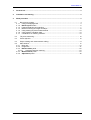
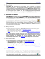
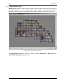
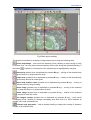
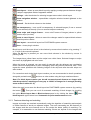
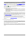
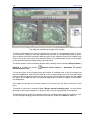
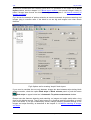
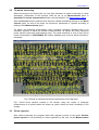
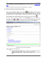
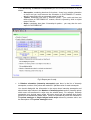
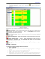
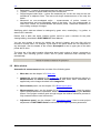
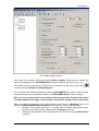
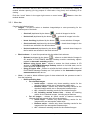
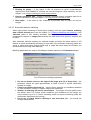
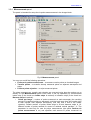
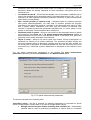
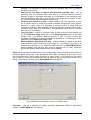
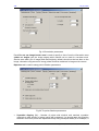
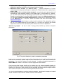
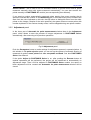
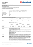
Software PHOTOMOD 4.4 Module PHOTOMOD AAT USER MANUAL Racurs, Moscow, 2009 PHOTOMOD 4.4 1. General info................................................................................................................................... 3 2. Installation and starting ............................................................................................................... 3 3. Work procedure ............................................................................................................................ 3 3.1 Block layout creating.............................................................................................................. 3 3.1.1 Using overlapping areas .................................................................................................... 3 3.1.2 Block layout window ........................................................................................................ 5 3.1.3 Features detecting and matching ...................................................................................... 7 3.1.4 Manual matching of images and strips .............................................................................. 8 3.1.5 Using existing tie points measurements .......................................................................... 10 3.1.6 Using exterior orientation data......................................................................................... 10 3.1.7 Combination of matching methods .................................................................................. 10 3.2 Tie points measuring............................................................................................................ 12 3.3 Points rejection..................................................................................................................... 12 3.4 Report viewing and measurements editing.......................................................................... 13 3.5 Main window ........................................................................................................................ 17 3.5.1 Menu bar.......................................................................................................................... 19 3.5.2 Images list........................................................................................................................ 21 3.5.3 Block scheme panel....................................................................................................... 22 3.5.3.1 Automatic features matching .................................................................................. 23 3.5.4 Measurements panel...................................................................................................... 24 3.5.5 Adjustment panel ........................................................................................................... 29 © 2009 2 AAT July 25, 2009 1. General info PHOTOMOD AAT (Automatic Aerial Triangulation) module is intended for automated creating of block layout of initial images and subsequent automatic tie points measuring using this block layout. PHOTOMOD project should be on Measurement stage and interior orientation of all images meant for further exterior orientation should be completed. If there are ground control points available, they can be measured (transferred) automatically, however GCP are not necessary. After automatic ties measuring the project could be transferred to Block adjustment stage and adjusted in PHOTOMOD Solver module. 2. Installation and starting PHOTOMOD AAT is installed along with the PHOTOMOD system by starting setup.exe file from the installation CD. See also readme.txt file on your CD for the installation instructions. This module is a plug-in for PHOTOMOD Montage Desktop. PHOTOMOD AAT is started from PHOTOMOD Montage Desktop program (see the corresponding User Manual) by the command Operations | Automatic tie point measurement or by pushing the icon on Project manager panel. At that current project should be on Block measurement stage. If the project is on some other processing stage, this menu item is disabled. If there is no such item in menu make sure that in plug-in list (Service | Preferences… | Plugins) Automatic tie point measurement plug-in is marked. 3. Work procedure Automatic measurement of tie points in PHOTOMOD AAT consists of the following stages: - Block layout creating, see the chapter 3.1 Block layout creating - Block measuring, see the chapter 3.2 Tie points measuring - Report creating and editing, see the chapter 3.4 Report viewing and measurements editing Note. These operations could be started both for the whole images block (creating of block layout and point measuring operations) and for its part (operation of automatic features detecting and matching and also all operations used for points measurement), see the chapter 3.5.2 Images list about images and strips selection 3.1 Block layout creating You can create block layout of images in the module using the following ways: - Using overlapping areas, see the chapter 3.1.1 Using overlapping areas - In Block layout window, see the chapter 3.1.2 Block layout window - Features detecting and matching, see the chapter 3.1.3 Features detecting and matching - Manual matching of images, see the chapter 3.1.4 Manual matching of images and strips - Exterior orientation data, see the chapter 3.1.6 Using exterior orientation data - By combining of manual and automated methods, see the chapter 3.1.7 Combination of matching methods. 3.1.1 Using overlapping areas If the initial images set is formed in more or less right order and overlapping areas between strips and images are visible in 2D window, it would be enough to perform automatic initial block layout, using this overlap. This operation is automatic and is started using the option Initial approximation: overlap in Block scheme panel or by pushing the button 3 Use RACURS Co., Ul. Yaroslavskaya, 13-A, office 15, 129366, Moscow, Russia PHOTOMOD 4.4 overlap in upper button bar of Automatic tie point measurement window. If images and strips overlap size is almost the same for the entire block, it is enough to input the appropriate overlap values in % into numeric fields to start block layout creation. Overlap values by default are 60 and 20 % for images and strips correspondingly. Fig.1 Automatic tie point measurement window © 2009 4 AAT July 25, 2009 3.1.2 Block layout window Block layout window is used for block scheme manual creation by moving and rotating of separate images and the whole strips. Block layout method is the most pictorial and is especially helpful in case of considerable shift of strips in relation to each other (see Fig.2). Fig.2 Block scheme in 2D window The Block layout window is opened by menu command Operations | Block layout in PHOTOMOD Montage Desktop module. 5 RACURS Co., Ul. Yaroslavskaya, 13-A, office 15, 129366, Moscow, Russia PHOTOMOD 4.4 Fig.3 Block layout creating The window is intended for creating of images block layout using the following tools: select strip/image – turns on/off the selecting mode, allowing to select image or strip by mouse click. You may select several strips by mouse click along with pressed Ctrl key, if the button is pushed. Central point of the selected strip is highlighted by red point. move strip (pushed icon is duplicated by pressed M key) – moving of the selected strip by drag-and drop or by keyboard arrow keys rotate strip (pushed icon is duplicated by pressed N key) – rotation of the selected strip by drag-and drop around its central point move strip rotation center (pushed icon is duplicated by pressed H key) – moving of strip rotation center by drag-and-drop move image (pushed icon is duplicated by pressed B key) – moving of the selected image by drag-and drop or by keyboard arrow keys rotate image (pushed icon is duplicated by pressed V key) – rotation of the selected image around its lower left corner set images overlap (pushed icon is duplicated by pressed S key) – turns on/off overlapping mode, allowing to change overlapping area size from 0 to 100% between all images in the strip simultaneously selected strip properties – calls a window allowing to change the overlap % between images of the selected strip © 2009 6 AAT July 25, 2009 reset layout – allows to reset block layout by applying overlap percent between images and/or strips in appropriate fields of appeared window settings – calls the window for selecting images texture size in block layout show navigation window – opens/hides navigation window located rightward to the main window show all – fits the block scheme to the window use transparency – turns on/off a transparency of selected images (if one or several images are selected) or the strip (if one or several strips are selected) show strips and images frames – turns on/off frames of images (shown in yellow color) and/or strips (in violet) revert to saved layout – allows to cancel the changes made for opened block scheme and reload its previous status save layout – saves block layout into PHOTOMOD system resource close – closes plug-in window. Block layout could be zoom in/out in the window by mouse wheel rotation or by pressing “*” or “/“ keys of the numeric keyboard. When the Alt key is pressed you can move block scheme in the window by mouse in panning mode. The images have yellow frame and the strips have violet frame. Selected images or strips are shown by highlighted red color frame. When the image is selected, you can match it manually with the adjacent one considering terrain contours superposition in their overlapping area using above mentioned tools. Then repeat the same operation with following images of the strip and after that with strips one after another. For convenient work during block layout creation you are recommended to do all operations along with pushed button , and turn on other modes using hot keys mentioned above. Note. For block layout creation you should not match terrain features on images with absolute precision, matching accuracy up to 10-20% of image size is enough (working zoom at that is about 2-3 %) When the work is over save the block layout into PHOTOMOD system resource (by pushing the button ). Then you can use it for automatic matching of block images, by checking the option Block layout data in Block scheme panel or by clicking the button block layout in upper button bar of Automatic tie point measurement window. Use 3.1.3 Features detecting and matching Images and strips are matched automatically using the algorithm of searching and analysis of similar features of terrain on adjacent images. The more contrasting are the features on the images and the more features are on the terrain the better quality of matching. For example, it is reasonable to use features matching if there are objects on the images with 7 RACURS Co., Ul. Yaroslavskaya, 13-A, office 15, 129366, Moscow, Russia PHOTOMOD 4.4 clear recognizable contours (agricultural fields). In case of monotonous terrain represented on images (wooded or mountainous, for example) this method would not work surely and it is recommended to use either manual links (see the chapter 3.1.4 Manual matching of images and strips) or block layout window (see the chapter 3.1.2 Block layout window). To turn the operation on, mark the option Feature matching data in Block scheme panel or Use feature matching data in upper button bar in Automatic Tie click the button points measurement window. Images’ matching by features is performed in two stages: • Features detecting. Usually the most time consuming operation. Is performed fully automatically and do not require user intervention. The result is saved automatically and used for further process. • Features matching. Is performed automatically (the result depends considerably on specified parameters, that is why it is recommended to test the algorithm on some part of the block first). After that the program performs approximate relative orientation of images inside strips and of strips with each other – this data is the first approximation for the process of tie points measuring. If some images or strips could not be matched automatically, you can match them manually in 2D window of PHOTOMOD Montage Desktop module, see the chapter 3.1.4 Manual matching of images. Note. After start of automatic features detecting and matching operation it is not recommended to stop the process by clicking the button Cancel in progress bar Refer to the chapter 3.5.3.1 Automatic features matching for detailed description of matching parameters. 3.1.4 Manual matching of images and strips If some images or strips could not be matched automatically (by features matching method), it is necessary to match them manually in 2D window of PHOTOMOD Montage Desktop module by approximate identifying (with accuracy at least several hundreds of pixels) of two pairs of corresponding points for each pair of images or strips. Manual links method in most cases is more effective in comparison with block layout, however when the strips of the images block are shifted significantly relatively to each other, it would be hard to put manual links since you should scroll the image in 2D window while working. © 2009 8 AAT July 25, 2009 Fig.4 Manual matching of images in 2D window To link any two images you may just indicate any two pairs of corresponding points on them. To link any two strips you may also indicate any two pairs of corresponding points on them. Pairs of points should be selected in different parts of the images to make more reliable links (and of course you may make more than two links). It is recommended first to link all images in strip and after that start strips linking with each other. The block scheme view is available anytime after selecting menu command Block scheme | Refresh or pushing the button measurement window. Refresh block scheme in Automatic Tie points To link two points on the images place the marker in selected point of the first image and press the Insert key, then place the marker in the corresponding point of the second image (yellow rubber line directing from the first point to the second appears) and press the Insert key again. Press Esc key after first pressing Insert key to cancel tie adding, at that rubber line disappears. Ties added are shown on the block scheme in 2D window by red lines, as shown on the Fig.4. To delete tie use menu command Clear | Delete manual matching data. You can delete ties both on the single image and on group of them using the appropriate menu options. To delete single tie, select it by double click or by pressing S key when the marker is near. The line linking matching points becomes bold and you should click Delete to delete it. 9 RACURS Co., Ul. Yaroslavskaya, 13-A, office 15, 129366, Moscow, Russia PHOTOMOD 4.4 Fig.5 Manual links for 6 images block To include manual matching results into block layout creation, check the option Manual links in Block scheme panel or push the button Automatic Tie points measurement window. Use manual links on upper button bar in 3.1.5 Using existing tie points measurements In addition to the methods of block scheme creation described above you can use preliminary measured tie points (in PHOTOMOD АТ, for instance, or during previous sessions of automatic tie measurements). Mark the option Existing tie points in Block scheme panel or push the button Use tie points on upper button bar in Automatic Tie points measurement window to include these points into matching process. 3.1.6 Using exterior orientation data If you have results of external block orientation imported to PHOTOMOD using the option Import exterior orientation in PHOTOMOD Montage Desktop, as well as block scheme created using external orientation, by projection centers of images, performed in PHOTOMOD AT module (see the appropriate User Manual), you can use this data during tie point’s measurement. For that push the button Use exterior orientation data on upper button bar in Automatic Tie points measurement window or check the option Exterior orientation data in Block scheme panel. 3.1.7 Combination of matching methods In most cases it is recommended to combine several methods of images and strips tying. For example, if images depict clear terrain features it is better to use feature-matching method. If © 2009 10 AAT July 25, 2009 strips have considerable shift relatively each other it is preferable to link strips first in Block layout window, see the chapter 3.1.2 Block layout window. And manual images’ linking is better if images were formed into block correctly (see the chapter 3.1.4 Manual matching of images and strips). Fig.6 shows the example of options selection to execute automatic tie points measuring and images tying in common case: if the block is not too big and images have clear terrain features. Fig.6 Options set for creating “simple” block layout If you need to consider ties not only between images but also between strips during block scheme creation, check the option Bind strips in Block scheme panel or push the button Bind strips on upper button bar in Automatic Tie points measurement window. Please note that features detecting and matching on images and strips would take a long time for big blocks enough. That is why better to try features matching algorithm on some part of the block. If you get unsatisfactory results, change matching process settings or link images and strips manually, as described in the chapter 3.1.4 Manual matching of images and strips. 11 RACURS Co., Ul. Yaroslavskaya, 13-A, office 15, 129366, Moscow, Russia PHOTOMOD 4.4 3.2 Tie points measuring When block layout has been build you can start automatic tie points measuring on block stereopairs. Parameters of this process could be set up on Measurements panel in Automatic Tie points measurement window, see the chapter 3.5.4 Measurements panel. After the Execute button is pushed, block layout is created considering settings on the Block scheme panel, as well as tie points are measured, transferred or rejected according to settings of the Measurements panel. Tie points are measured automatically using correlation algorithm. Besides there is an automatic rejection of points by residual vertical parallax, by triplets and using measured points transfer inside strip and between strips. Tie points measured in such a way will be saved automatically in PHOTOMOD AT module database and could be edited manually if necessary. Fig.7 Results of automatic tie points measurement on the big block Fig.7 shows block scheme created in 2D window using the results of automatic measurement of tie points (which are shown as yellow circles) for block consisting of 250 images. 3.3 Points rejection After points measuring, the program starts their rejection process (if the option Perform points rejection is on) according to criteria specified by the user on the Measurements © 2009 12 AAT July 25, 2009 panel in Automatic Tie points measurement window, see the chapter 3.5.4 Measurements panel. Points could be rejected by two main ways: using triplets or Y-parallax. 3.4 Report viewing and measurements editing Menu command Service | Report (or the button Show report) opens the window containing the report on the current status of the relative orientation of the project, with a full process statistics related with stereopairs, triplets, interstrip stereopairs etc. You can open the report only for the images selected in the list in left panel, by checking menu item Service | Report for checked images only (duplicated by pushed menu button ). The report could be saved as HTML file or as PHOTOMOD resource (by pushing the and ). Also the report is opened automatically after the process appropriate buttons of automatic tie point’s measurement is completed (after pushing the button Execute). Fig.8 Report on tie points measurement Report consists of the following parts: • Strips o Result of relative orientation table – shows the list of stereopairs, number of common points and maximal Y-parallax (dY) for each stereopair o Residuals for triplets table – shows maximal residuals for X,Y and Z, and RMS 13 RACURS Co., Ul. Yaroslavskaya, 13-A, office 15, 129366, Moscow, Russia PHOTOMOD 4.4 In the Necessary conditions for adjustment part the following information (if any) is shown: o Stereopairs, containing less than 6 tie points – there is no relative orientation on them and you could execute the orientation in PHOTOMOD AT module, which is opened by click on stereopair name in this list o Triplets, containing less than 3 common points – you could add ties into these triplets in PHOTOMOD AT module, which is opened by click on triplet name in this list o Strips, containing less than 3 interstrip tie points – you may also tie such strips in PHOTOMOD AT. Fig.9 Report part for strip • In Relative orientation (Interstrip stereopairs) part there is the list of interstrip stereopairs, number of tie points and maximal Y-parallax value for each stereopair. You should distinguish the information in the report about interstrip stereopairs and about linked strips shown in the Number of interstrip points section (interstrip points which were not transferred in strips may be existed there). For example, interstrip stereopairs may include many points, but strips would not be matched since these points are not transferred inside strips. These non-transferred points are indicated in Tie points catalogue in Single images inside strips column by nonzero value, see the description of Tie points catalogue below. © 2009 14 AAT July 25, 2009 Fig.10 List of interstrip stereopairs Click underlined stereopairs or triplets to open them in AT. So the idea is that you can add some more points in PHOTOMOD AT before starting the Block Adjustment process in PHOTOMOD Solver. • • In Stereopairs with non-uniform points distribution part there is a list of stereopairs where automatically measured tie points are located on the image irregularly. You can open such stereopair in PHOTOMOD AT, and measure points on necessary places. At that non-uniform points distribution means that there are less than two points in any of 6 equal areas, which the overlap area is conventionally divided on. The list of Triplets with non-uniform points distribution. If you divide the area of triple images overlap into 3 parts by Y axis, the triplet is considered as “bad” if at least one of the parts does not contain tie points. Note. Stereopairs, triplets and strips containing points that exceed the threshold, are highlighted by red color in the report After tie points adding and/or editing (in PHOTOMOD AT) click the Refresh link located under report’s title to update the report. This will result in recalculating of relative orientation and creation of new report. In the upper part of report window you can select the type of data to be shown in the report: ▪ General report – opens by default. ▪ List of “bad” stereopairs – includes stereopairs without relative orientation (less than 6 tie points) ▪ List of “bad” triplets – opens a list of triplets with less than 2 tie points (such triplets will produce adjustment error in PHOTOMOD Solver). 15 RACURS Co., Ul. Yaroslavskaya, 13-A, office 15, 129366, Moscow, Russia PHOTOMOD 4.4 ▪ Tie points catalogue (is opened also by the button points list: ) – opens the following tie Fig.11 Tie points list Buttons in the upper button bar are intended for the following: Edit on all images – opens the window of selected point editing on all images where it was measured, see detailed description of editing in PHOTOMOD AT User Manual. Duplicated by double click on point record. Search by point name – allows to search the point in the list by its name, duplicated by hot keys Ctrl-F. Delete selected points – deletes selected points and their measurements from the list. Export selected points – allows to export points selected in the list with all measurements into external file (xpt). File has a simple XML format and could be edited using any text processor when needed. Import points – allows to load points from external xpt file, adding them to points existing in the list. Close – closes the list. The catalogue includes the following columns for each point: • Name – point name • Type – ground control or tie • Auto – whether the point is measured automatically (“+” symbol) or manually (“-” symbol) • Images – number of images where the point is measured • Strips – number of strips where the point is measured • Single images – points are measured just on the one image of stereopair and are not transferred to other ones. The less such single measurements on the strip the better © 2009 16 AAT July 25, 2009 • • • • Stereopairs – number of stereopairs where the point is measured Triplets – number of triplets where the point is measured Single images inside strips – points are measured just on the one strip and are not transferred to adjacent ones. The less such single measurements on the strip the better Measured on non-overlapped strips – measurements of points, located on non-intersecting and non-overlapping strips of the block. You are recommended to check this column for measurements and delete points, measured mistakenly on non-existing overlaps of images. Satisfying point’s data are shown in catalogue by green color, unsatisfying – by yellow, to attract user’s attention. Double click a table raw which contains point's record to open a window for the point viewing/editing, described in PHOTOMOD AT User Manual. You can sort records in column by clicking the column’s header, and next click will sort records in reverse order. For example, if you need to see points which are not measured on any stereopair, click the header of the column Stereopairs to see in upper part of the table points with 0 value. The lower bar of the table contains information about total number of points, measured on the block, also including ground control and tie points measured both manually and automatically. 3.5 Main window Automatic tie measurement window consists of the following parts: 17 • Menu bar, see the chapter 3.5.1 Menu bar • Images list, see the chapter 3.5.2 Images list. All operations checked as options on Measurements and Block scheme panels and also some menu commands are applied only to the images checked in the Images list • Block scheme panel, see the chapter 3.5.3 Block layout panel • Measurements panel, see the chapter 3.5.4 Measurements panel. Used for setting options and parameters of operations, which are executed after pushing the Execute button. If the project contains good enough images the relative orientation process is fully automatic without user intervention. • Adjustment panel, see the chapter 3.5.5 Adjustment panel. Used to start project adjustment in PHOTOMOD Solver module and to set up the process parameters. RACURS Co., Ul. Yaroslavskaya, 13-A, office 15, 129366, Moscow, Russia PHOTOMOD 4.4 Fig.12 Main module window Lower part of the window contains the option When complete, which allows to choose the ways of completing work in PHOTOMOD AAT module: hibernate your PC or turn it off. The window could be reduced up to menu bar (or returned to its full size) by the button or menu command Window | Collapse/Expand. You may leave the window opened when starting PHOTOMOD AT module or when transfer to the adjusting stage or sub-block selection and PHOTOMOD Solver module starting. Note. It is not recommended to do anything in ties measurement window if the project is on Block adjustment stage, it could result in irreversible damage of the project data While the window of automatic ties measurement is open there is Matching layer in 2D window of PHOTOMOD Montage Desktop module which is used for the following: • Viewing of the project topology, i.e. images pairs compiled using block layout, which are used for tie points measurement (Topology sub-layer) • Viewing of links between points tied manually on block layout stage (Manual links sub-layer). © 2009 18 AAT July 25, 2009 You should remember that the data necessary for orientation is automatically loading at module window opening (for big projects it could take a long time) and unloading at its closing. Push the “cross” button in the upper right corner or menu button module window. Close to close the 3.5.1 Menu bar Contains the following items: • Images – is used to select or deselect images/strips to start processing for the selected part of the block. • o Check all (duplicated by the button o Uncheck all (duplicated by the button o Invert checking (duplicated by the button o Check selected (duplicated by the button list which are selected in the block scheme o Uncheck selected (duplicated by the button the list which are selected in the block scheme o o 19 ) – uncheck all images in the list ) – invert selection of images ) – check those images in the ) – uncheck those images in Block scheme – is used for operations with the whole block scheme. o • ) – check all images in the list Refresh (duplicated by the button ) – allows to re-build block of images in 2D window of PHOTOMOD Montage Desktop module considering options marked in Automatic matching window Without using layout data – allows to restore the block scheme in 2D window of PHOTOMOD Montage Desktop module to its initial state, and to cancel previous images tying Using all layout data – allows to re-build the block scheme in 2D window of PHOTOMOD Montage Desktop as if all options in the Automatic tie point measurement window are on Clear – is used to delete different types of data related with the process to start it from the beginning o Delete matching data For checked images • Inside strips – deletes only those matching results for the checked images which are on stereopairs inside strips • Between strips – deletes only those matching results for the checked images which are on stereopairs between strips • All – deletes all matching results for the checked images • All, including cached feature lists – deletes all matching results for the checked images, including saved features For all images – deletes all saved results of features matching (features lists and manual links will not be deleted) • Inside strips – deletes only those matching results for the images which are stereopairs inside strips • Between strips – deletes only those matching results for the images which are stereopairs between strips • All – deletes all matching results for the checked images RACURS Co., Ul. Yaroslavskaya, 13-A, office 15, 129366, Moscow, Russia PHOTOMOD 4.4 • o o o o All, including cached feature lists – deletes all matching results for the checked images, including saved features Delete manual matching data All – deletes all manual links For checked images – deletes manual links only between images checked in the list Delete auto calculated tie points For checked images – deletes tie points measured automatically only on checked images All – deletes tie points measured automatically on all images (automatically measured points are those measured using Automatic matching plug-in. At that GCP and manual links, measured then automatically, will be preserved) Single points – deletes tie points measured automatically on less than two images Single points inside strips – deletes tie points measured automatically on the only one strip Delete manual tie points Single points – deletes tie points measured manually that were not transferred to the adjacent images Single points inside strips – deletes tie points measured manually that were not transferred to the adjacent strips Delete “redundant” points – deletes points measured only on this stereopair (which are not transferred to the other models, in order to preserve ties in triplets and between strips), if their number exceeds the number specified in the window opened. First of all you can delete points measured with minimal correlation coefficient, or points with maximal vertical parallax, depending on the option selected. Fig.13 Parameters of “redundant” points deleting • © 2009 Service – is used to open the Report showing the current state of relative orientation of block images o Report (duplicated by the button ) – opens report window with current status of the project relative orientation. The report is created instantly after selecting this command o Tie points list (duplicated by the button ) – shows the window containing the list of tie points, used to view and edit them on the images, see the chapter 3.4 Report viewing and measurements editing 20 AAT July 25, 2009 Report for checked images only (duplicated by the button ) – opens report window with current status of the project relative orientation only for images checked in images list. Window o • o • ) – roll Automatic matching Collapse/Expand (duplicated by the button window up to menu bar or return it to the full size. Rolled window is suitable during images manual linking and when starting and working in PHOTOMOD AT or PHOTOMOD Solver modules ) – closes Automatic matching window. o Close (duplicated by the button Help – opens User Manual (duplicated by F1 key). 3.5.2 Images list For images and/or strips selection use the panel located in left part of the PHOTOMOD AAT window, which contains the list of the project images. The list is represented as a tree of strips and images included to strips. Strip marking/unmarking results in selecting/unselecting of all images of this strip. The following menu commands or buttons allow to do the following: - Check all images - Uncheck all images - Invert checking of images - Check selected images - Uncheck selected images Note. You can select images and strips only for automatic features matching and point measurement, but block layout is created for the whole block 21 RACURS Co., Ul. Yaroslavskaya, 13-A, office 15, 129366, Moscow, Russia PHOTOMOD 4.4 3.5.3 Block scheme panel The panel is intended for setting the parameters of block scheme creating from initial images block of PHOTOMOD project. Fig.14 Block scheme panel Block scheme is created for images checked in Images list using the following options: ▪ ▪ ▪ ▪ Initial approximation: overlap – allows to create block layout automatically, using overlap between images and strips, see the chapter 3.1.1 Using overlapping areas Block layout data – allows to create block scheme using results of images matching performed in Block layout window, see the chapter 3.1.2 Block layout window Feature matching data – it is recommended to turn this option on if images contain clear terrain features to be used for images matching, see the chapter 3.1.3 Features detecting and matching Manual links – it is recommended to match some strips or images manually if during automatic matching they are not matched correctly, see the chapter 3.1.4 Manual matching of images © 2009 22 AAT ▪ ▪ ▪ July 25, 2009 Existing tie points – if the option is ON, all previous tie point’s measurements (performed in PHOTOMOD AT module) are used for images or strips matching, see the chapter 3.1.5 Using of existing tie points measurements Exterior orientation data – allows to consider imported exterior orientation data for tie points measurement, see the chapter 3.1.6 Using exterior orientation data Bind strips – if the option is ON, matching is performed also for strips not only for images. 3.5.3.1 Automatic features matching When using feature matching for block layout creating, mark the option Feature matching data in Block scheme panel, see the chapter 3.1.3 Features detecting and matching. If the Calculate option is ON, existing automatic matching data will be re-calculated on all images/strips checked in Images list otherwise the data saved from previous sessions will be used. After automatic features matching for selected images and strips the block scheme in 2D window is rebuilt automatically according to new data. If the automatic matching results are wrong or some block parts (images inside strip or strips with each other) left unlinked, you should match them using other methods. Matching parameters are setup in the dialogue window opened by the Parameters button: Fig.15 Features matching parameters • • • • 23 Do not use feature closer to the edge of the image than (% of image size) – this parameter should be equal approximately to width of area of service information located on images. Feature correlation threshold (%) – has the same meaning as correlation threshold of usual correlator. Usually no need to change the parameter. Number of matching options for each feature – for images of normal quality leave the default value. For unclear terrain conditions (just woodlands on the image) you may increase it up to 2-3. Further increasing would not improve matching quality but slows down significantly the process. Do not try to match features differing in size more than (%) – you should not change the parameter. RACURS Co., Ul. Yaroslavskaya, 13-A, office 15, 129366, Moscow, Russia PHOTOMOD 4.4 3.5.4 Measurements panel The panel is intended for setup the tie points measurements in the images block. Fig.16 Measurements panel You may turn on/off the following operations: • Perform tie points measurement – to measure new tie points on checked images. • Transfer points – to transfer already measured points on adjacent stereopairs and strips. • Perform points rejection – to reject measured points. Tie points measurement, transfer and rejection are executed using also the options set up directly on the Measurements panel. Each value is set up separately for measurement inside strip (if the check box Inside strips is marked) or between strips (if the check box Between strips is marked): ▪ Points per image – number of points measured on each stereopair (the resulting amount of measured points on stereopair could be both more than this number (due to their transfer from adjacent stereopairs), and less than it due to the further rejection). Default number of points inside strips is 30 and between strips is 10. Minimal number of points needed for control of residual vertical parallax – 6. The parameter is used only for new tie points measurement (the option Perform tie points measurement is on) and specifies total amount of points measured on © 2009 24 AAT July 25, 2009 ▪ ▪ ▪ ▪ stereopair, after which new points search stops. For instance, if more points than the parameter allows are already measured on some stereopair, new points will be not measured on it. Correlation threshold – the minimal acceptable value of correlation coefficient for tie point to be accepted during automatic search. Recommended value is 0.92 – 0.97. In contrast to all other rejection criteria this parameter influences on point measurement and transfer process directly. Max. vertical parallax (in camera units) – threshold value for rejection executed after points measuring/transfer. On each step of rejection process the program searches for the point with maximal Y-parallax on the stereopair and rejects it. After that it makes relative orientation once more and the iteration is executed until maximal Y-parallax exceeds the parameter specified here, or until 6 points or less remain on stereopair. Recommended value is half pixel. Distribute points in zones – allows to use zones on the stereopair where tie points are measured. Use Zones tab in Tie points measurement parameters window to adjust parameters of such zones, see description below. If the option is off, points are measured on the entire stereopair area uniformly. Reject in zones – allows to use zones (each zone means 1/6 part of stereopair) on stereopair for filtering of tie points measured. The operation provides filtering the worst (by parallax) points on stereopair, passing zone by zone one after another. So the worst point on stereopair is found and deleted first, then the worst one in the next zone and so on. Uniformity of point’s distribution on stereopair is also verified in such a way. You can adjust measurement parameters in the window Tie point measurement parameters opened by the button Parameters on the Measurements panel: Fig.17 Tie points measurement parameters The window consists of the following tabs: Correlating points – the tab is intended for adjusting parameters of automatic tie points search on the images. Usually there is no need to change default values: • Enlarge search area when feature matching data available (%) – automatically matched data is used for preliminary evaluation of search area for correlation 25 RACURS Co., Ul. Yaroslavskaya, 13-A, office 15, 129366, Moscow, Russia PHOTOMOD 4.4 • • • • algorithm. It is necessary to enlarge this area on specified value (50 – by default) for reliable processing. Search area size when no feature matching data available (pix) – size of searching area for correlator when there was no (or failed) features matching between images of stereopair and there is no evaluation of the searching area. You should enlarge this value (up to 20-30% of the image size perhaps), if there are some difficulties with automatic ties measuring. Contrast point search area (pix) – default value is 100. The parameter is used for tie points search in areas of maximal contrasts (images with clear object’s features). In some cases it is advisable to measure points in areas with low contrast (for example, when maximal contrast corresponds to woods areas, where correlator errors have high probability). The parameter value may be reduced there up to 10 for example. Tries per point – number of correlation tries for each point out of the number set by the Points per image parameter on the Measurements panel of the main window (100 – by default). Maximal amount of tries to found a point with correlation coefficient not less than threshold specified is a multiplication of this parameter by the Points per image value. Minimal distance between points (pix) – minimal distance in pixels of the initial image between points measured on the image (5 – by default). You may try to increase the parameter if it is difficult to adjust the block in PHOTOMOD Solver module (please note that this limit could be applied only to newly measured points, and already measured points will be not filtered). Zones tab is intended for selection of areas on stereopair, where automatic points search is executed. Select zones size in the appropriate field (100% correspond to zone size of 1/6 part of overlap area). There is also a scheme of zones (from 1 to 6) where you can select any number of zones by checking them on the scheme. More details about zones of tie points search using correlator see in PHOTOMOD AT User Manual. Fig.18 Selection of stereopair zones for correlator work Correlator – the tab is intended for setting correlator parameters. Refer to appropriate chapter in PHOTOMOD АТ User Manual. © 2009 26 AAT July 25, 2009 Fig.19 Correlation parameters Panel Do not use image border area is used to specify a size of service information area (width and height near the image edges) which should not be used for correlator work. Service area width (2% of image width and height by default) should not be less than on the image, otherwise a big amount of wrong points would be measured in image service areas. Rejection tab is used to setup point’s filtration parameters: Fig.20 Tie points filtration parameters 27 X-parallax clipping (%) – Number of points with minimal and maximal x-parallax (relatively to total amount of points) which will be deleted. You should apply this rejection method if erroneous points are dispersed clearly along stereopair basis (if, for example, a RACURS Co., Ul. Yaroslavskaya, 13-A, office 15, 129366, Moscow, Russia PHOTOMOD 4.4 highway with bright marking goes in parallel to survey basis and correlator puts points on marking line elements, which do not correspond with each other). Maximum triplet residual (in camera units) – maximal difference of points measurements on adjacent stereopairs in triplet zone. Default value both in plane and in height – 0.04. Delete points with correlation below threshold – when there are tie points measured automatically using correlator (either in PHOTOMOD AAT or PHOTOMOD AT module), you can filter these points after specifying the threshold value on the main window. It is suitable to use the option for recurrent point’s filtration, when in the Measurements panel only the option Perform tie points measurement is checked, and in parameters window on the Rejection tab – only this option is marked. See also the chapter 3.5.4 Measurements panel. Points measured on single images or strips could be rejected if the appropriate options are on. It is recommended to turn the option on if you are not going to use bundle adjustment, because in this case these points will be not involved in adjustment. Rejection by angles – the tab is used to setup point’s filtration by relative orientation parameters: Fig.21 Tie point’s filtration by relative orientation parameters In some cases automatic measurements of tie points result in some rotation of images in the block due to erroneous points, and incorrect measurement of their relative orientation parameters. You can view values of angle elements of relative orientation parameters in PHOTOMOD AT module on the tab # 4, see an appropriate User Manual. If you are sure that images should not be rotated, you can prevent possible rotation by filtering of measured tie points considering their rotation angles. On this tab change angles threshold (in degrees) for each element of the stereopair, and points caused images rotation after relative orientation more than threshold specified will be filtered. You are not recommended to use this rejection method for blocks where images are rotated actually, because in this case ties located correctly will be deleted. © 2009 28 AAT July 25, 2009 Points transfer – tab is used to turn on automatic transfer of ground control and tie points measured manually along with points measured automatically. You can also transfer the points manually in PHOTOMOD АТ module (see corresponding User Manual). If you need to number automatically measured points starting from some number that is specified, indicate this number on the Numbering tab. In this case these point’s numbers will start from the value indicated on this tab, that will allow to distinguish them from the other points on the images. Despite of the value specified, the system does not create points with number duplicated. If the number already exists, it will be skipped during new points creation. 3.5.5 Adjustment panel In the lower part of Automatic tie point measurement window there is the Adjustment panel, which allows to start the process of images adjustment in PHOTOMOD Solver automatically, after executing of all previous operations. Fig.22 Adjustment panel Push the Parameters button to make settings for adjustment process in opened window. In this window in Tie point rejection panel you can set up the options of automatic filtering of measured tie points: worst points and over acceptable residuals. See also PHOTOMOD Solver User Manual. If the option Adjust in PHOTOMOD Solver is on, after pushing the Execute button marked operations will be performed, the project will be transferred to automatically Adjustment stage. Then it will be adjusted in PHOTOMOD Solver module, the report block adjustment will be created and Automatic tie point measurement window will closed. 29 all on on be RACURS Co., Ul. Yaroslavskaya, 13-A, office 15, 129366, Moscow, Russia