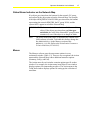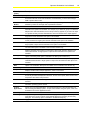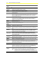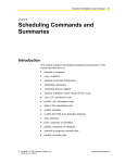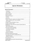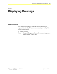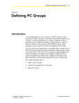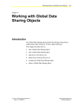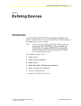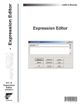
1
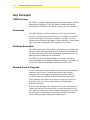
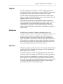
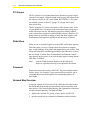
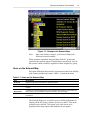
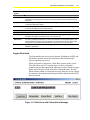
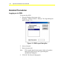
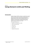
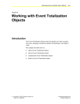
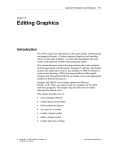
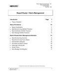
Operator Workstation User’s Manual 1-1 Chapter 1 Getting Started Introduction This chapter explains Metasys Operator Workstation (OWS) concepts and how to log on and log off the OWS. This describes how to: • log on an OWS • log off an OWS Note: This section assumes the Metasys Building Automation System (BAS) is installed and running. For information on installing and commissioning Metasys software, refer to the Operator Workstation Technical Bulletin (LIT-636013). © November 1, 2001 Johnson Controls, Inc. Code No. LIT-120165 www.johnsoncontrols.com 1-2 Operator Workstation User’s Manual Key Concepts OWS Overview The OWS is a graphics-based interface that provides advanced facility management capabilities. The OWS gathers information from the network and consolidates it into facility-wide reports and summaries. Summaries The OWS displays a variety of summaries. Each type of summary focuses on a specific aspect of the facility. For example, an Override summary lists objects in software or hardware override. A Critical summary lists all alarms and changes-of-state defined as Critical report types. Operators can schedule when summaries are printed. Database Generation The OWS archives data. For example, alarm histories, trend data, and totalized values can be uploaded from the Network Control Modules (NCMs) and stored in files at the workstation. Operators can view or print the archived data from the workstation. The OWS can create the initial database for a facility and edit an existing database to accommodate additions or changes. Operators can also use the OWS to download the databases into the NCMs. Network Control Programs Use the workstation to download the control processes that control the operation of the facility. Create the processes on any Personal Computer (PC) with Graphic Programming Language (GPL) or JC-BASIC, then use the OWS to download them into the NCMs. The workstation can connect to a network over the N1 Local Area Network (LAN), or it can be connected to an NCM through a dedicated serial port. With a modem and phone line, operators can use one workstation to control more than one remote network or control one network with more than one workstation. These multiple workstations can act with the same level of functionality, allowing for decentralized control while retaining complete integration of information. Operator Workstation User’s Manual 1-3 Objects An object generally corresponds to an actual field point or control process in the facility. For example, an object called RET-FAN might correspond to a relay contact wired to a return air fan, control processes (Proportional plus Integral plus Derivative [PID] loops or routines created in GPL) and hardware such as the workstation itself, a lighting controller, an NCM, or a printer. The OWS allows operators to display detailed online information about all the objects in a facility. Operators can monitor the current value and status of objects and display point history, trend, and totalization data. Operators can also command an object from any window displaying the object and schedule commands to take place at specific times. Attributes Each object has a number of attributes that characterize it. For example, an object’s name, current value, and high alarm limits are all attributes. Some attributes are assigned values when the object is originally defined. For example, the object name is assigned in the object’s Definition window. Other attributes reflect the realtime status of the object. For example, the current value of the object is dynamic data and changes according to field conditions and control processes. View and modify attributes in Object Focus windows. Systems Objects are grouped together in systems. For example, all the hardware and software objects related to the operation of one air handling unit might comprise system AHU1. To uniquely identify an object, the OWS uses both its system name and object name. For example, AHU1\RET-FAN is the system\object name of an object corresponding to a particular return air fan in the AHU1 system. The entire Metasys system knows whether this fan is On or Off because the continuously updating databases contain records of current values and states for all objects. These records are kept according to the object’s system\object name. 1-4 Operator Workstation User’s Manual PC Groups The PC group level of organization allows operators to group related systems. For example, operators might want to group all systems from one side of a facility in a PC group called WESTWING. A PC group can contain systems or other PC groups. PC groups can be up to three levels deep. The PC group level is for the convenience of the operator only. Since it is not global data, it is unique to the workstation where the group is defined and is not used by the Metasys program to identify objects (only system\object names are used to identify objects). However, PC group names are included in change-of-state and alarm reports at the workstation to help operators quickly locate the source of alarms. Slide Show When no one is currently logged on to the OWS, a slide show appears. This slide show is a series of images that can represent a company logo, or the buildings, floor plans, and equipment in your facility. Each image is displayed for a defined period before the slide show cycles to the next image. If a slide show is not defined, the Johnson Controls logo appears on the screen, or an error message appears stating that no slide show is defined. Note: Critical Alarm messages display over the slide show. However, operators must log on to respond to the alarms. Password Passwords protect the security of the BAS. The password determines facility access. For example, if your password does not allow you to command objects, the menu options for commanding objects are unavailable. Network Map Overview A network consists of at least one NCM, all the devices connected to this NCM and all the hardware and software objects associated with these devices. The Network Map displays the organization of the most recently activated network. The Network Map: • displays the network, PC group, system, device, and PC file • provides quick access to summary information within facilities Operator Workstation User’s Manual 1-5 Figure 1-1: Example of a Network Map Note: Since each facility is unique, your Network Map looks different from this example. When operators expand the Network Map, all the PC groups and systems in the network appear. Filtering allows operators to view all the systems within a network, regardless of their assigned PC group. Items on the Network Map Each item defined for the network is represented on the Network Map with a button and the item’s name. Table 1-1 explains the items. Table 1-1: Items on the Network Map Item Description PC Group Displays all the PC groups within the specified network System Appears as the lowest level on the Network Map Devices Contains all the PCs, Network Control Modules (NCMs), and printers defined for the network PC File Report Destinations Contains a PC file report destination for archived BAS data including: critical, follow-up, status, history, trend, totalization, operator transaction, and card reader Systems Contains names of systems that have not been assigned to any particular PC group on the network The Network Map gives you quick access to facility information. It displays all the PC groups, systems, N1 devices, and PC files in the currently active network. The system level is the lowest level displayed on the map (objects and attributes do not appear). 1-6 Operator Workstation User’s Manual Each network, PC group, system, and device is represented by both a button and a boxed-in name on the Network Map. Clicking on buttons or names produces different effects, depending on the types of items they represent. Table 1-2 shows what occurs when operators click or double-click on each type of item represented on the Network Map. Table 1-2: Using the Mouse with Buttons and Names on the Network Map Item Action Result Network Button Click Expands network to show each PC group within the network Network Name Double-click Displays Network summary PC Group Button Click Expands to show each PC group and system within the PC group PC Group Name Double-click Displays PC Group summary System Button Click Displays System Peek dialog box System Name Double-click Displays System summary DEVICES Button Click Expands to show all of the devices defined for the network DEVICES* Double-click Displays the Devices summary Device Name Double-click Displays the device’s Focus window PC File Name Double-click Displays the Reports Destination summary SYSTEMS Button Click Displays all systems on the network that are not assigned to any other PC group SYSTEMS* Double-click Displays PC Group summary * Actual text appearing on the Network Map Operator Workstation User’s Manual 1-7 Global Alarm Indicator on the Network Map If an object goes into alarm, the buttons for the network, PC group, and system for the object turn red on the Network Map. For example, if the object HDQTRS\NC44\AHU1\BI4 goes into alarm, the buttons representing the network HDQTRS, the PC group NC44, and the system AHU1 appear in red on the Network Map. IMPORTANT: The button color indicates the last reliable state of the object. If the object goes into alarm, and then goes unreliable, the color of the Network/PC group/System remains red, even if the object is no longer in alarm. Note: The Alarm Indication feature is automatically enabled when OWS software is loaded. To disable this feature, change the line ENAALMIND=0 in the Metasys section of the METASYS.INI file. Refer to the Initialization Parameters Technical Bulletin (LIT-636345). Menus The Metasys software uses the same menu options in every workstation window (Table 1-3). There are two exceptions: the Action menu and the Network Map’s three additional menu bar options (Summary, SetUp, and Exit). The Action menu for each window contains options specific to that window. For example, the Action menu in an Object Focus window displays options for commanding an object. The Action menu in the Trend Item window displays options for setting up the collection of trend data. 1-8 Operator Workstation User’s Manual Table 1-3: Network Map Menus Menu Option Description Item Menu New Allows you to define new items such as new networks, PC groups, systems, or objects Save Saves any changes you make in a window File Transfer Transfers files from any OWS to another OWS on the network. Note: The destination device cannot be the same as the source device (you cannot transfer files to the same PC). Print Prints the current contents of the window Change Printer Changes the specified destination for printouts of summaries and screen displays Delete Deletes the selected item About Displays information about the workstation software, including a revision number and date of release Edit Menu Copy Copies the selected text to the Clipboard Paste Only applies to the Scheduling window. Used in conjunction with the Copy option, Paste allows you to copy a schedule from one day of the week to another. Cut Only applies to the Scheduling window. Used in conjunction with the Paste option, Cut allows you to move a schedule from one day of the week to another. View Menu Show as Text Displays the PC group or system as a textual list of items rather than as a drawing. This option also displays Trend and Totalization information as textual summaries rather than as line or bar graphs. Show as Drawing Displays the PC group or system as a drawing rather than as a textual list of items. This option also displays Trend and Totalization information as line and bar graphs rather than as textual summaries. Sort The Sort option allows you to change the order in which items appear on the current screen. Different windows have different sort options. Note: The Sort function is different from the System/Object Display Order function. The Sort function applies to the current screen display and is effective for only as long as the screen is displayed. The System/Object Display Order function permanently alters the order in which systems or objects appear in summaries and printouts. Filter Filters out items displayed on the current screen Current Page Displays the current page All Pages Displays all networks, PC groups, and systems on the Network Map Actual Size Displays the drawing in actual size Zoom Zooms in or out on the drawing Action Menu Diagnostics Initiates diagnostics on the selected network, N1 device (NCM, PC, printer), or N2/L2 device (for example, DCM, XM). For example, you can generate a printout of complete network configuration data. NC Download Downloads the archive NCM database into the selected NCM. An NCM must be selected on the Network Map for this option to be available. NC Upload Copies the operational NCM database to the archive NCM database. An NCM must be selected on the Network Map for this option to be available. Download Global Data Downloads the archive global database from the workstation to the operational global database Upload Global Data Copies the operational global database to the archive global database stored at the workstation Continued on next page . . . Operator Workstation User’s Manual Menu Option (Cont.) 1-9 Description Action Menu (Cont.) Archive Data Archives current Trend and Totalization data to the Trend and Totalization archive summaries. Because Trend and Totalization are NCM-based, you must select a single NCM to perform this function. Print COS Buffers Provides on demand printing of Change-of-State (COS) messages. COS messages can be buffered by number of messages and a specified time interval. Go To Menu Selected Item Displays the summary or Focus window of the selected item. A single item must be selected for this option to be available. For example, if you select PC group in the Network Map and then click Selected Item, the PC Group summary appears. If you select an object in a System summary and click Selected Item, the Focus window for the object appears. Schedule Displays the Scheduling window where you can schedule commands and summaries. A single item must be selected for this option to be available. Process Displays the Process window. In this window, you can download GPL and JC-BASIC control processes. A single system must be selected for this option to be available. Trend Displays the Trend Item window. In this window, specify how trend data is collected. A single system or object must be selected for this option to be available. Trend Data Displays the Trend Data window where you view collected trend data for selected objects. The Trend Data option is available in the Trend Item window only. History Displays the History Item window. In this window, select which objects to display in the History Data window. A single system or object must be selected for this option to be available. History Data Displays the History Data window where you view the collected history data for selected objects. The History Data option is available in the History Item window only. Totalization Displays the Totalization Item window. In this window, select which objects to display in the Totalization Data window. A single system or object must be selected for this option to be available. Totalization Data Displays the Totalization Data window where you view totalization data for selected objects. The Totalization Data option is available in the Totalization Item window only. Accessory Menu Notepad Displays the Microsoft Notepad application, which is a text editor Clock Displays the Clock window Control Panel Displays the Microsoft Control Panel application. Control Panel allows you to change the time of day and date as displayed in the Clock, set the cursor speed, select screen colors, and perform other basic setup functions. Calculator Displays the Microsoft Calculator application. The Calculator provides basic math functions. Clipboard Displays the Microsoft Clipboard application. Detailed information on Clipboard is in your Windows operating system manual. Custom Applications Allows you to use other applications, such as Microsoft Excel or XTM Configurator Tool without closing the Metasys system. To open other software using this option, it first must be added to the Custom Applications menu. Summary Menu Summary Displays a dialog box listing the available summary types. For many summaries, operators must select a PC group or system on the Network Map before accessing the Summary dialog box. The Summary option is available in the Network Map only. Continued on next page . . . 1-10 Operator Workstation User’s Manual Menu Option (Cont.) Description Setup Menu Scheduling Calendar Displays the Scheduling Calendar, which allows operators to specify whether the days in a calendar year are Regular, Alternate, or Holiday Daylight Saving Displays the Daylight Saving dialog box, which allows operators to specify when the workstation software will switch to daylight saving time Password Displays the Password summary, which allows operators to set up and modify the password database N2 Dial Displays the N2 Dial Network summary, which lists all remote sites defined on the network that are connected via the N2 Dialer Module (NDM). From this summary, operators can dial out to an NDM remote site, disconnect from an NDM remote site, or refresh the summary using the Action menu. Network Displays the Network summary, which lists all the networks in the facility. From this summary, operators can display a Network Focus window to view and modify network configuration or a Network Definition window to add a new network to the facility. Operators can also activate a network. Report/Access Groups Displays the Report/Access Group summary, which allows operators to define and modify report/access Groups 1-16. Enhanced Report/Access Groups Displays the Enhanced Report/Access Group summary, which allows operators to define and modify report/access Groups 17-32 PC Configuration Displays the PC Configuration window, which allows operators to set up the ports on the workstation the operators are using IP Address Configuration Displays the Internet Protocol (IP) Address Configuration summary, allowing operators to display and modify the IP addresses of directly connected N1 devices on the Ethernet LAN. Alarm Messages Displays the Alarm Message summary. Since alarm messages are NCM-based, a single NCM must be selected on the Network Map for this option to be available. The Alarm Message summary lists all alarm messages stored in the selected NCM and allows operators to add, delete, and modify messages. System/Object Display Order Displays the System/Object Display Order dialog boxes, which allows operators to permanently alter the order in which systems and objects appear on the screen and printed. This function differs from the Sort function because a Sort is only effective for the currently displayed screen. Modify Group Assignment Displays the Modify Group Assignment dialog box, which allows operators to move a system from one PC group to another. Operators must select one system on the Network Map for the option to be available. Software Models Displays the Software Model summary that allows operators to define software models, either new, or by copying an existing model PC User Options Displays the PC User Options dialog box that allows operators to specify what windows open when operators click on a Network Map item with a mouse, and what size the windows will be. Operators can also choose to display expanded IDs for each item on the Network Map using this dialog box. Exit Menu Logoff Program Manager Logs operators off the workstation and displays the slide show. Metasys system continues operating, and Critical Alarm messages appear on the screen to immediately inform operators of Critical alarms. However, until operators log on again, the operator’s only option is to acknowledge the alarm by clicking the Look Later button. Displays the Program Manager. When operators click the Program Manager option, a dialog box appears, asking whether operators want to keep the Metasys BAS running. Note: If operators choose to close the BAS when operators exit, the operator transaction may not be received at all destinations before the BAS stops running. If operators want to record the exit to program manager, leave the BAS running. Continued on next page . . . Operator Workstation User’s Manual Menu Option (Cont.) 1-11 Description Exit Menu (Cont.) GPL Logs operators off, closes the workstation software, and accesses the Graphic Programming Language (GPL) program. Only certain password levels are allowed to use this option. Designer Starts Micrografx Designer software, either closing or leaving the BAS open, depending on operator’s Metasys software Backup Utility Starts the backup or restore utility. Submenus of the Backup Utility option allow operators to choose either Backup Data or Restore Data. Help Menu Using Help Displays instructions for using online help Attribute Help Displays help about the attribute which the operators are defining, modifying, or viewing. This option is available in Definition and Focus windows only. Operating Instructions Displays the operating instruction for the selected object in the Notepad Editor. Operators can view or modify the instruction or create a new instruction for the selected object. The object’s operating instruction number appears in the object’s Focus window. This number corresponds to the Notepad Editor text file that contains instructions for the object. Feature Help Displays the Feature Help submenu, allowing operators to access help on Metasys Metalink applications Logon Overview The Logon dialog box accesses the Operator Workstation (OWS) and the Metasys System. Passwords determine which functions and systems operators can access. When no operator is logged on, a slide show appears on the screen. This slide show can be a company logo or a series of dynamic graphical images that represent the operator’s facility. Alarm messages appear on the screen over the slide show. During this time, the only alarm action available is clearing the message from the screen. Logged on operators can manage alarms and perform the functions allowed by their passwords. Figure 1-2: Slide Show with Critical Alarm Message 1-12 Operator Workstation User’s Manual Detailed Procedures Logging on to OWS To log on to the OWS: 1. From the Windows Start menu, select Programs > Johnson Controls > Metasys. The Logon dialog box appears (Figure 1-3). Figure 1-3: FMS Logon Dialog Box 2. Select a Network. 3. Enter your password. Note: 4. If 30 seconds elapse between mouse clicks or keystrokes during the log-on process, the Logon dialog box automatically disappears. Click OK. The Network Map appears. Operator Workstation User’s Manual 1-13 Logging off Operator Workstation To log off the Operator Workstation: 1. On the Menu, click Logoff. The Network Map dialog box appears (Figure 1-4). Figure 1-4: Logoff Dialog Box 2. Click Yes or No.