1
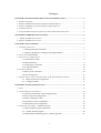
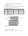
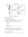
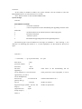
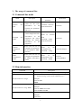
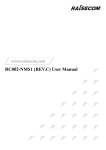
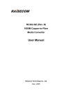
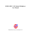
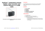
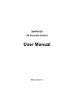
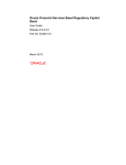
RC004-16 NMS1
(REV.B)
User Manual
Beijing Raisecom Science & Technology Co., Ltd
April 2005
1
Catalogue
CHAPTER 1 SYSTEM COMPONENTS AND ITS INTRODUCTION ........................................... 3
1、RC004-16 CHASSIS ......................................................................................................................... 3
2、RC004-16 NMS1 MASTER NETWORK MANAGEMENT MODULE ..................................................... 4
3、RC004-16 NMS2 SLAVE NETWORK MANAGEMENT MODULE ........................................................ 5
4、AGENT PROGRAM .......................................................................................................................... 6
5、NETWORK MANAGEMENT PLATFORM AND NETWORK ELEMENT MANAGER ................................... 6
CHAPTER 2 HARDWARE INSTALLATION .................................................................................... 6
1、 RC004-16 NMS1 INSTALLATION ................................................................................................... 6
2、RC004-16 NMS2 INSTALLATION .................................................................................................... 6
CHAPTER 3 AGENT SETTING .......................................................................................................... 7
1、COMMON CONNECTION ................................................................................................................... 7
1、Managing through CONSOLE....................................................................................7
2、Support long-distance management through TELNET...............................................7
2、THE USAGE OF BOOTROM ............................................................................................................ 7
3、THE USAGE OF COMMAND LINE ....................................................................................................... 9
3.1 Command line mode ...................................................................................................9
3.2 Help information .........................................................................................................9
3.3 Using history command ............................................................................................10
3.4 Using edit attribute....................................................................................................10
4、SYSTEM COMMAND ....................................................................................................................... 10
4.1 Basic system command .............................................................................................10
4.2 User management......................................................................................................11
5、THE RELATED FUNCTION CONFIGURATION OF THE NETWORK MANAGEMENT ............................... 12
5.1 Ethernet interface configuration.............................................................................12
5.2、Configure SNMP....................................................................................................13
CHAPTER 4 SYSTEM MAINTENANCE......................................................................................... 17
1、TASK ............................................................................................................................................. 17
2、CONFIGURE FILE MANAGEMENT .................................................................................................... 18
2.1 Check the information of the configured files...........................................................18
2.2 Save the present configuration ..................................................................................18
2.3 Delete configuration files..........................................................................................19
2.4 Upload the present configuration ..............................................................................19
2.5 Download system configuration ...............................................................................19
3、START FILE MANAGMENT(AGENT PROGRAM)......................................................................... 20
3.1 Check AGENT program information ........................................................................20
3.2 Upload AGENT program .......................................................................................20
3.3 Download the AGENT program(AGENT upgrade) ............................................21
2
Chapter 1 System components and its introduction
1、RC004-16 Chassis
The RC004-16 chassis is 10U high and has 16 slots, which could provide
power supply to every operation interface module for Raisecom (including optical
transceiver, transmitter, receiver, protocol converter and etc.).
The details are as following
Part number
Description
Size( mm )
Power supply
RC004-16AC
With Network
Management Agent, 16
slot AC chassis
436×440×360
220V AC,50Hz,150W
RC004-16DC
With Network
Management Agent, 16
slot DC chassis
436×440×360
-48V DC,150W
The figure of the front panel
The meaning of the indicator light:
PWR light:Green, on, the power supply is in normal
PS1 light:Red, off, the power module in the No. 1 power slot is in normal; whereas it has
problem.
3
PS2 light:Red, off, the power module in the No. 1 power slot is in normal; whereas it has
problem.
Warning Output Terminal: Controlled by the Master Module or Slave Module in the slot of
the Network Manager of the chassis. If the Network Management Module is not installed, this
terminal will not work.
2、RC004-16 NMS1 Master Network Management Module
RC004-16 supports SNMP network management through the RC004-16 NMS1 network
management module in the No. 0 slot.
Model specification
RC004-16 NMS1(REV.B) Master control Module of the chassis, which is Rack mounted;
Panel figure
1、Panel LED indicator light:
SYS: Green, the operation light of the Network Management Module system. When the
CPU operates in normal, it is flickering, otherwise, it is abnormal.
PWR:
Green, the power light of the Network Management Module. When the power
is on, it is on.
ALM:
Red。 When there is any warning in this chassis, it is on.
100M: Green, speed indicator. When the Ethernet working speed is 100M, it is on; When
the speed is 10M, it is off.
LNK/ACT:Green,network state indicator light. When the connection of the Ethernet wire
is in normal, it is on; If there is data transmitting on the network, it is flickering.
RX: Green,data receiving indicator light. When there is serial data input, it is flickering.
TX: Green, data transmitting indicator light. When there is serial data output, it is
flickering.
2、RJ-45 interface of the panel:
ETHER:
10M/100M Ethernet interface. When connecting to the Ethernet Switch,
straight-through cable is used. When connecting to the host computer, cross-over cable is
used.
CONSOLE:
Console interface. It could be connected to the computer Serial port by
using the RS-232 cable.
DOWN(1\2\3): Downward cascade interface:The UP interface of the Slave control
module could be connected to using the straight-through cable. This cable uses the RS-485
standard.
4
The main function of the Master control module:
The ETHER Ethernet interface of every Master control module has an IP address. The
default address is 192.168.1.254. The IP address of every Master control module in the same
LAN cannot be the same. Please configure the Master control module state using the
CONSEL console interface, including the newly configured IP address.
The main function of the Master control module:
1. 10/100 M Ethernet interface is used to connect the Network Management Manager
computer.
2. Communicating with the Slave Module, realizing the cascade with the chassis.
3. Configuring or collecting the working state and warning message of the function
module in the 1 to 15 slots. The module is in this chassis or the cascade chassis.
4. Connecting the temperature, rotating speed of the fan and power module state of
this chassis and the cascade chassis.
5. Controlling the warning output terminal of this chassis and the cascade chassis.
3、RC004-16 NMS2 Slave Network Management Module
Panel figure
1、The meaning of the indicator light:
PWR:Green. When the power works in normal, it is on.
ALM:Red. When there is any warning in this chassis, it is on.
TX:Green. When there is serial data output, it is flickering.
RX:Green.When there is serial data input, it is flickering.
2、RJ-45 interface on the panel:
UP:The DOWN1-3 interface connecting to the Master control module using the straight-through
cable. This interface uses the RS-485 standard.
The rack mount 16-slot chassis installed with the RC004-16 NMS1 Master control module
can cascade maximum three rack mount 16-slot chassis installed with the RC004-16 NMS2 Slave
control module. In other words, a network management Master control module can manage
maximum 60 function modules. There is no limit on the number of Master control module in the
5
LAN.
4、AGENT program
Store and Run the AGENT program on the RC004-16 NMS1 to realize the realization of the
Network Management function. This program will upgrade with the products.
The program edition of the AGENT program for RC004-16 NMS1(REV.B)is above 3.X.X
(Different edition of AGENT software needs different edition of BOOTROM program).
5、Network Management platform and Network Element Manager
They are the software installed on the network management server in the user’s computer
room. Please refer to the ‘NVIEWNNM_3.1.2(SP2) installation manual’ and the
‘NVIEWNNM_3.1.2(SP2) operation manual’.
Chapter 2 Hardware installation
1、 RC004-16 NMS1 installation
The front panel of the RC004-16 NMS1 has 5 interfaces:
CONSOLE interface(RJ-45)is used to connect to the simulation terminal to carry out the
initial configuration installation. The parameter is the default value of the super terminal (Baud
rate: 9600; Data bit: 8; Parity: None; Stop bit: 1; Data flow control: None.)
ETHER Ethernet interface(RJ-45),10/100Mbps self-adaptive. It is used to connect to the
TCP/IP management network to communicate with the Network Management platform. When
connecting to the Switch, the straight-through cable is used; When connecting to the host
computer, the cross-over cable is used.
DOWN(1\2\3):Connect to the RC004-16 NMS2 on the other three chassis through the
Serial wire; the interface is RS-485. Straight-through wire is used.
RC004-16 NMS1 can only be installed on the leftmost No. 0 slot on the chassis.
2、RC004-16 NMS2 installation
The front panel of the RC004-16 NMS2 has one interface, which is for cascade. It could be
connected to the RC004-16 NMS1 Master Network Management module using the
straight-through wire to realize the increasing of the number of the manageable module. One
Master module can support maximum 3 Slave module, that is it could support the management of
maximum 60 function module. The connection topology figure is as following:
6
Chapter 3 AGENT Setting
1、Common connection
1、Managing through CONSOLE
Connecting the COM interface of the PC terminal to the CONSL interface of the RC004-16
NMS1 Master Network Management Module using the Serial wire.
In the WINDOWS system, run the ‘hyper terminal’ program in the system itself, or the third
Serial interface connecting software, and configure the default parameters as following:
Baud rate:9600;
Data bit:8;
Parity:None;
Stop bit:1;
Flow control:None
Click ‘ENTERS’ for several continuous times, and you are able to see the system CLI
interface and manage the equipment.
2、Support long-distance management through TELNET
After setting the initial IP address for RC004-16 NMS1 through CONSOLE interface, the
long-distance management of RC004-16 NMS1 through TELNET can be realized.
2、The usage of BOOTROM
In the BOOTROM mode, users can manage and maintain the FLASH memory and the files
7
stored in it.
In the startup of RC004-16 NMS1, the system interface will ask whether to enter the
BOOTROM mode or not. The time limit is 3 seconds.
Press ‘SPACE’ button to enter the BOOTROM mode.
System Prompt
raisecom:
BOOTROM commands:
?
- list all the commands
c
- correct the parameters when downloading the upgrading firmware in the
FTP mode.
e
- the flash subarea of the format firmware (AGENT program)
h
-list all the commands
r
-reboot the system
u
-Download the upgrading firmware through FTP protocol
The following part is the introduction to the usage of command ‘c’. After running ‘c’, the
interface is as following (the content in “/* */”is the explanation, viz, the content for the users to
input.
raisecom: c
'.' = clear field;
'-' = go to previous field;
^D = quit
boot device
: sng0
processor number
:0
host name
: host
file name
: RC999
upgrading */
inet on ethernet (e) : 192.168.223.64
appointed as you wish */
inet on backplane (b):
host inet (h)
: 192.168.223.98
gateway inet (g)
:
user (u)
: raisecom
ftp password (pw) (blank = use rsh): 123
flags (f)
: 0x0
target name (tn)
: agent
startup script (s)
:
other (o)
:
/*The name of the downloading file for
/*The present IP of this equipment, it can be
/*The IP of the FTP server */
/*FTP User name*/
/*FTP User password*/
8
3、The usage of command line
3.1 Command line mode
Mode
Way for entering mode
(Default)
Description
Mode Mark
In this mode, the user
could see the basic
information
of
the
terminal, the parameters
and so on.
Username:raisecom
Password:raisecom
raisecom>
In this mode, the user
could configure the basic
information
of
the
equipment, but cannot
configure the running
information
of
the
equipment.
Based on common
mode
Command:enable
Password:raisecom
raisecom#
CONFIG
configuration
mode
In this mode, the user can
configure the parameters
of the RC004-16 NMS1
interface.
Based
on
the
privileged mode,
Command:config
raisecom(config)#
SNMP
configuration
mode
In this mode, the user can
configure the parameters
of SNMP of RC004-16
NMS1.
Based
on
the
configuration mode,
Command:SNMP
raisecom
(config-SNMP)#
Common
mode
user
Privileged
mode
user
3.2 Help information
Command
Description
help
A short description from the help system (Chinese, English)
Specified character string?
Obtain the list of all the commands starting with a specified
character string(abbreviated-command-entry).
Example:
raisecom>en?
enable
Specified character string <Tab>
Complete an incomplete input command
Example:
raisecom #show ver<TAB>
raisecom#show version
?
List all the command in the present mode
Example:
raisecom#?
9
command ?
List all the key words and options of a command, and its
short help information.
raisecom#show ?
3.3 Using history command
In the buffer storage, the default system keeps 20 history commands. Users can configure the
number through
raisecom#terminal history <0-20>
Using command history to show the past input command history.
3.4 Using edit attribute
up arrow:
The above input command;
down arrow: The next input command;
left arrow: Move to the left for one character;
right arrow: Move to the right for one character;
backspace:
Delete the character before the cursor;
Ctrl+d:
Delete the character after the cursor;
Ctrl+a:
Move the cursor to the head of the line;
Ctrl+e:
Move the cursor to the end of the line;
Ctrl+k:
Delete all the characters after the cursor;
Ctrl+z:
Enter the privileged user mode form other modes;
4、System command
4.1 Basic system command
clear
Clear the displayed information on the screen
enable
Enter the privileged user mode
exit
Return to the above command mode or quit the logon
state
help
Use this command to display the help information in the
system
history
Use this command to display the past input commands
list
Use this command to display all the command in the
present mode in the list
show ip
Display the ip address
show sntp
Display the related information of sntp
ping A.B.C.D
ping ip address is the equipment of A.B.C.D
quit
Use this command to return to the command mode of the
above command or quit the logon state
terminal history <1-20>
Change the number of the history commands input by the
console.
terminal time-out <0-65535> Use this command to change the configuration information
10
when the console terminal quits because of overtime.
disable
Use this command to quit the privileged user mode to
return to the primary mode
logout
Use this command to quit the logon state
reboot
Reset the RC004-16 NMS1 Master Network Management
module
show version
Display the system version information
show terminal
Display the terminal running situation of the system
write
Save the present configuration information of the
present system
4.2 User management
The default username of the system: raisecom; Password: raisecom. This user is super user.
Adding user
Procedure
Command
Description
1
user USERNAME password
PASSWORD
z
z
z
USERNAME Username;
password Key word of password;
PASSWORD Password information;
2
user USERNAME privilege
<1-15>
z
z
z
USERNAME
Username;
privilege Key word of privilege
<1-15>
User privilege
3
password
Change the password in the logon state
4
no user USERNAME
Delete the user named USERNAME
5
write
Save the configuration information
6
show user
Display the user information
4.2.1 Deletion of users
【Command】
no user USERNAME
【Command mode】
Privileged configuration mode; privileged user (privilege 15)
【Guide】
In the database of system user, there at least one user whose privilege is 15; Only the
user with the privilege 15 can use this command.
【Command Execution Echo】
You have no enough right to change user information!
When the user wants to create a new user without the privilege 15, this prompt will show.
At this time, user can logout and logon with the privilege 15.
11
5、The related function configuration of the Network Management
5.1
Ethernet interface configuration
Related configuration of IP protocol,which need to run in the CONFIG mode.
5.1.1 Enter CONFIG mode
【Command】
Based on the privileged mode
config
【Command Execution Echo】
raisecom(config)#
5.1.2 Configure IP address
【Command】
ipaddr A.B.C.D mask A.B.C.D gateway A.B.C.D
【Command Execution Echo】
set command success
please execute "write" to save!
【Example】
Set the RC004-16 NMS1 address to 192.168.223.89,mask is 255.225.255.0,gateway is
192.168.223.1
raisecom(config)#ipaddr 192.168.223.89 mask 255.225.255.0 gateway 192.168.223.1
5.1.3 Configure the auto negotiation of the Ethernet interface
【Command】
autonego (enable|disable)
【Command Execution Echo】
set command success
if you want to save it, please execute "write" to save!
【Example】
Enable RC004-16 NMS1 auto negotiation of the
raisecom(config)#auto enable
Ethernet
interface :
5.1.4 Configure the speed and Duplex mode of the Ethernet interface
【Command】
speed (10|100) duplex (full|half)
【Command Execution Echo】
set command success
if you want to save it, please execute "write" to save!
【Example】
Set RC004-16 NMS1 Ethernet interface to 100M Full Duplex:raisecom(config)#speed
100 duplex full
12
5.1.5 Display the Ethernet interface information
【Command】
show ether
【Command Execution Echo】
STAUS:
link up
AUTO:
enable
Speed:
100M
Duplex:
FULL
【Example】
raisecom(config)#show eth
5.2、Configure SNMP
Related configuration of the SNMP protocol,it need to run in the CONFIG-SNMP
mode.
y 5.2.1 Enter SNMP mode
All the related configuration of SNMP protocol is need to run in the SNMP mode.
【Command】
Based on CONFIG mode
snmp
【Command Execution Echo】
raisecom(config-SNMP)#
y 5.2.2 Configure the community name
【Command】
snmp-server community COMMUNITY (ro|rw)
【Description】
Set read-only community(ro)and write-only community(rw)
【Example】
raisecom(config-SNMP)# snmp-server community public ro
y 5.2.3 Open or close TRAP
【Command】
snmp-server trap (enable|disable)
【Description】
Open or close TRAP
【Example】
raisecom(config-SNMP)# snmp-server trap enable
y 5.2.4Configure the MANAGER and interface number of TRAP
【Command】
snmp-server trap <1-8> target A.B.C.D port <1-65536>
【Description】
13
Configure the MANAGER and interface number of TRAP. trap: set the sequence of the
MANAGER(one can bet set with eight ones)
target: IP address of the MANAGER;PORT: interface number
【Example】
Set the first TRAP address;its IP address is 192.168.1.1;interface number,162
raisecom(config-SNMP)# snmp-server trap 1 target 192.168.1.1 port 162
y 5.2.5Delete TRAP MANAGER
【Command】
no snmp-server trap <1-8>
【Description】
Delete a TRAP MANAGER
【Example】
raisecom(config-SNMP)# no snmp-server trap 1
y 5.2.6 Delete all the TRAP Manager configuration
【Command】
snmp-server trap clear
【Description】
Delete all the TRAP Manager configuration
y 5.2.7Configure the information of CONTACT
【Command】
snmp-server contact STRING
【Description】
Configure the information of CONTACT
【Example】
Set the contacting information to“admin”
raisecom(config-SNMP)# snmp-server contact admin
y 5.2.8 Set ID information
【Command】
snmp-server id <0-65536>
【Description】
Set ID information
【Example】
Set the ID to“5”
raisecom(config- SNMP)# snmp-server id 5
y 5.2.9 Set LEVEL information
【Command】
snmp-server level <0-65536>
【Description】
14
Set LEVEL information
【Example】
Set LEVEL information to 5
raisecom(config- SNMP)# snmp-server level 5
y 5.2.10Set LOCATION information
【Command】
snmp-server location LOCATION
【Description】
Set LOCATION information
【Example】
Set the equipment located in“haidian”
raisecom(config- SNMP)# snmp-server location haidian
y 5.2.11 Set NAME information
【Command】
snmp-server name NAME
【Description】
Set the equipment name information
【Example】
Set the equipment name to“RC004”
raisecom(config-SNMP)# snmp-server name RC004
y 5.2.12 Set the valve value of the system temperature
【Command】
snmp-server temperature <0-100>
【描述】
Set the valve value of the system temperature. When the temperature is higher than this
value, the system will send TRAP information to the Network Management platform.
【Example】
Set the valve value of the system temperature to 20
raisecom(config-SNMP)# snmp-server temperature 20
y 5.2.13 Load community
【Command】
load default community
【Description】
Load the default configuration of COMMUNITY
【Example】
raisecom(config-SNMP)#load default community
y 5.2.14 Inquire of the SNMP information
【Command】
show snmp
15
【Description】
Display SNMP configuration information
【Example】
raisecom(config- SNMP)# show snmp
System name:
unknown
System contact: unknown
System location: unknown
System ID:
1
System level:
1
System Temperature Alarm Threshold: 50
Read Community:public
Write Community:private
Send trap status:
Enable
Trap sink
Target Address
Target Port
1
0.0.0.0
162
2
0.0.0.0
162
3
0.0.0.0
162
4
0.0.0.0
162
5
0.0.0.0
162
6
0.0.0.0
162
7
0.0.0.0
162
8
0.0.0.0
162
5.3 Configure SNTP
The system supports SNTP(system net time protocol)CLIENT,obtain the real time of the
system.
It is necessary to configure in the CONFIG mode.
5.3.1 Enter CONFIG mode
【Command】
Based on the privileged mode
config
【Command Execution Echo】
raisecom(config)#
5.3.2 Configure this computer to the client of SNTP receiving broadcast message
【Command】
sntp broadcast client
【Description】
Configure this computer to the client of SNTP receiving broadcast message
【Example】
raisecom(config)# sntp broadcast client
5.3.3 Cancel this computer’s configuration of the client of SNTP broadcast
16
【Command】
no sntp broadcast client
【Description】
Cancel this computer’s configuration of the client of SNTP broadcast
【Example】
raisecom(config)# no sntp broadcast client
5.3.4Obtain time from the specified SNTP SERVER
【Command】
sntp server A.B.C.D
【Description】
Obtain time from the specified SNTP SERVER
【Example】
Obtain time form computer 192.168.1.10
raisecom(config)# sntp server 192.168.1.10
5.3.5 Cancel obtaining time form the specified SNTP SERVER
【Command】
no sntp server
【Description】
Cancel obtaining time form the specified SNTP SERVER
【Example】
Cancel obtaining time form computer 192.168.1.10
raisecom(config)# no sntp server
Chapter 4 System maintenance
1、Task
Manage and configure files:Including checking in the system, saving the configuration
file; c; receiving from the outside memorizer.
Manage AGENT program:Including checking program information; exportting to the
outside memorizer for saving; upgrading the AGENT program.
When the configuration file and the AGENT program communicate with the outside
memorizer, the RC004-16 NMS1 acts as the client of FTP protocol. It is necessary to
configure the computer terminal where the outside memorizer located in to FTP server.
After the server specifying the user account, it is only needed to do some related
configuration in the RC004-16 NMS1 control interface.
17
2、Configure file management
¾
¾
¾
The present configuration of the system, store in files:
system.txt
hostconf.txt
slotconf.txt;
The configuration file could be saved to flash file system through command write.
When the system reboots the next time, the system will automatically load the
configuration information of the storage.
Use download/upload command ,as client,through FTP or TFTP protocol,configure
files mutually with the outside memorizer.
2.1 Check the information of the configured files
【Command】
dir (c:|d:)
【Description】
Function:Check the file information of the FLASH storing area
Parameter:
c: is the system file area.
d: is the configuration file area.
【Example】
Read the file in the configuration area
raisecom#dir d:
size
date
time
name
-------------------------------------------269
Jan-01-1980 00:00:00 hostconf.txt
1340
Jan-01-1980 00:00:00 system.txt
81
Jan-01-1980 00:00:00 usercfg.txt
7680
Jan-01-1980 00:00:00 slotconf.txt
2.2 Save the present configuration
【Command】
write
【Description】
Mode:Work in the privileged mode;
Function:Save the present configuration information of the system
【Example】
raisecom#write
Writing running-config to flash, please wait...
Successfully write to flash
18
2.3 Delete configuration files
【Command】
del FILENAME
【Description】
Mode:Work in the privileged mode;
Function:Delete configuration files.
【Example】
raisecom#del slotconf.txt
delete file slotconf.txt successfully.
2.4 Upload the present configuration
【Command】
upload startup-config (tftp | ftp)
【Description】
Mode:Work in the privileged mode;
Function:Upload the present configuration files in the system to the outside memorizer
through FTP or TFTP protocol
【Parameter】
Filename(system.txt;hostconf.txt;slotconf.txt)
system.txt:The related information in the AGENT about SNMP protocol, including:
TRAP IP address、port interface number、system contact method、system name、
location、community string、temperature valve value, enable alarms;
hostconf.txt:Information configuration in AGENT itself,including:IP address、mask、
the speed of the Ethernet interface、Duplex mode、auto negotiation enable or not and
some related configuration information of the sntp.
slotconf.txt:configuration information of the slot and card in the chassis.
【Example】
raisecom#upload startup-conf ftp
Please input server IP Address:192.168.1.251
Please input FTP User name:target
Please input FTP Password:target
Please input FTP Server File Name:slotconf.txt
2.5 Download system configuration
【Command】
download startup-config (tftp | ftp)
【Description】
Mode:Work in the privileged mode;
Function:Upload the configuration files in the outside memorizer to RC004-16 NMS1
19
system through tftp or ftp protocol
【Parameter】
Filename(system.txt;hostconf.txt;slotconf.txt)
【Example】
raisecom#download startup-config ftp
Please input server IP Address:192.168.1.251
Please input FTP User name:target
Please input FTP Password:target
Please input FTP Server File Name:hostconf.txt
Loading, please wait...
Loading: 268 ... done
Writing to flash, please wait...
.finished
You've successfully download new config file
new config works after the device reboots ...
3、Start file managment(AGENT program)
¾
¾
¾
AGENT program file is based on the embedded operation system, perform the SNMP
protocol function when the system power is on.
Use command dir to check the files in the flash file system;
Use show version to check the software version information
3.1 Check AGENT program information
【Command】
dir (c:|d:)
【Description】
Function:check the file information in the FLASH storing area
Parameters:
c: is the system area file
d: is the configuration area file
3.2
Upload AGENT program
【Command】
upload system-boot (tftp | ftp)
【Description】
Mode:Work in the privileged mode;
Function:Upload the present Agent program in the system to the outside memorizer
through tftp or ftp protocol
【Parameter】
Filename
20
【Example】
In the “/* */”, it is the explanation (viz the content for the user to input).
raisecom#upload system-boot ftp
Please input server IP Address:1.0.0.1
Please input FTP User name:test
Please input FTP Password:test
Please input FTP Server File Name: /*Any filename*/
3.3 Download the AGENT program(AGENT upgrade)
【Command】
download system-boot (tftp | ftp)
【Description】
Mode:Work in the privileged mode;
Function:Upgrade Agent program,through tftp or ftp protocol
【Parameter】
In the “/* */”, it is the explanation (viz the content for the user to input).
【Example】
raisecom# download system-boot ftp
Please input server IP Address:1.0.0.1
Please input FTP User name:test
Please input FTP Password:test
Please input FTP Server File Name: /*The Agent program filename on the outside
memorizer */
21