1
ALPHA
MICROSYSTEMS
RIGHT. FROM THE START.
ALPHA
MICROSYSTEMS
RIGHT. FROM THE START.
ALPHA
MICROSYSTEMS
RIGHT. FROM THE START.
ALPHA
MICROSYSTEMS
RIGHT. FROM THE START.
ALPHA
MICROSYSTEMS
RIGHT. FROM THE START.
ALPHA
MICROSYSTEMS
RIGHT. FROM THE START.
ALPHA
MICROSYSTEMS
RIGHT. FROM THE START.
ALPHA
MICROSYSTEMS
RIGHT. FROM THE START.
ALPHA
MICROSYSTEMS
RIGHT. FROM THE START.
ALPHA
MICROSYSTEMS
RIGHT. FROM THE START.
ALPHA
MICROSYSTEMS
RIGHT. FROM THE START.
ALPHA
MICROSYSTEMS
RIGHT. FROM THE START.
ALPHA
MICROSYSTEMS
RIGHT. FROM THE START.
AMOS
System Operator’s
Guide
DSM-00001-03
© 1996 Alpha Microsystems
REVISIONS INCORPORATED
REVISION
DATE
00
March 1988
01
December 1988
02
March 1991
03
September 1996
AMOS System Operator’s Guide
To re-order this document, request part number DSO-00001-00.
This document applies to AMOS 2.3 and later.
The information contained in this manual is believed to be accurate and reliable. However, no responsibility
for the accuracy, completeness or use of this information is assumed by Alpha Microsystems.
This document may contain references to products covered under U.S. Patent Number 4,530,048.
The following are registered trademarks of Alpha Microsystems, Santa Ana, CA 92799:
AMIGOS
AlphaBASIC
AlphaFORTRAN 77
AlphaMATE
AlphaWRITE
VIDEOTRAX
AMOS
AlphaCALC
AlphaLAN
AlphaNET
CASELODE
Alpha Micro
AlphaCOBOL
AlphaLEDGER
AlphaPASCAL
OmniBASIC
AlphaACCOUNTING
AlphaDDE
AlphaMAIL
AlphaRJE
VER-A-TEL
The following are trademarks of Alpha Microsystems, Santa Ana, CA 92799:
AlphaBASIC PLUS
AlphaDDE
inFront/am
AlphaVUE
AlphaConnect
ESP
AM-PC
DART
MULTI
All other copyrights and trademarks are the property of their respective holders.
ALPHA MICROSYSTEMS
2722 S. Fairview St.
P.O. Box 25059
Santa Ana, CA 92799
AMTEC
inSight/am
SYSTEM OPERATOR’S GUIDE
MASTER TABLE OF CONTENTS
PART 1 INTRODUCTION
Chapter
Chapter
1
2
What is a System Operator?
How to Use this Book
PART 2 SYSTEM ADMINISTRATION
Chapter
Chapter
Chapter
Chapter
Chapter
Chapter
Chapter
Chapter
Chapter
Chapter
Chapter
Chapter
Chapter
Chapter
Chapter
1
2
3
4
5
6
7
8
9
10
11
12
13
14
15
User Names
Disk Accounts and Passwords
User Protection Levels
Distributing Information to Users
System Information Commands
How to Create Help Files
What is a Driver Program?
Event Logging
Setting up Function Keys
Defining Ersatz Device Names
Language Definition Files
Patching Programs
The Disk Cache Buffer Manager
The Virtual Disk
Finding Information in Alpha Micro Documentation
PART 3 DISK MAINTENANCE
Chapter
Chapter
Chapter
Chapter
Chapter
Chapter
1
2
3
4
5
6
Disk Analysis and Troubleshooting Disks
Labeling and Identifying Disks
Handling Media Flaws on Winchester Disks
Backing up Your System
Warm Booting and Restoring a Disk
Consolidating Disk Files
System Operator’s Guide, Rev. 02
Page 2
Master Table of Contents
PART 4 SYSTEM CONFIGURATIONS
Chapter
Chapter
Chapter
Chapter
Chapter
Chapter
Chapter
Chapter
Chapter
1
2
3
4
5
6
7
8
9
Adding New Devices
Defining Non-System Disk Devices
Generating a System Monitor
Converting a Secondary Disk to a System Disk
Setting up the Task Manager Print Spooler
Floppy Disks
Configuring Winchester Disk Drivers
Magnetic Tape Drives
The AM-350 Intelligent I/O Controller
PART 5 DISK CONTROLLERS
Chapter
Chapter
Chapter
Chapter
Chapter
1
2
3
4
5
Introduction to Disk Controllers
The AM-415 and AM-420 Disk Controllers
The AM-515 SASI and SCSI Disk Controller
The AM-520 Disk Controller
SCSI Disks
PART 6 APPENDICES
Appendix
Appendix
Appendix
A
B
C
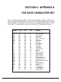
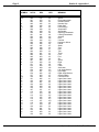
The ASCII Character Set
Event Logging Table of Events
System Error Codes
PART 7 DOCUMENTS
Document
Document
Document
1
2
3
Glossary
Document History
Index
System Operator’s Guide, Rev. 02
SECTION 1
INTRODUCTION
This section introduces the System Operator’s Guide and explains how to use the book.
System Operator’s Guide, Rev. 02
SECTION 1
TABLE OF CONTENTS
CHAPTER 1 WHAT IS A SYSTEM OPERATOR?
1.1 The Responsibilities of the System Operator . . . . . . . . . . . . . . . . . . . . . . .
1.1.1 System Administration . . . . . . . . . . . . . . . . . . . . . . . . . . . . . . . . . . .
1.1.2 Disk Maintenance . . . . . . . . . . . . . . . . . . . . . . . . . . . . . . . . . . . . . .
1.1.3 Changing the System Configuration . . . . . . . . . . . . . . . . . . . . . . . .
1.1.4 Troubleshooting . . . . . . . . . . . . . . . . . . . . . . . . . . . . . . . . . . . . . . . .
1
1
1
2
2
1.2 The System Operator Account . . . . . . . . . . . . . . . . . . . . . . . . . . . . . . . . . .
2
CHAPTER 2 HOW TO USE THIS BOOK
2.1 Other Reference Books . . . . . . . . . . . . . . . . . . . . . . . . . . . . . . . . . . . . . . .
1
2.2 How this Book is Organized . . . . . . . . . . . . . . . . . . . . . . . . . . . . . . . . . . . .
1
2.3 Revision Information . . . . . . . . . . . . . . . . . . . . . . . . . . . . . . . . . . . . . . . . .
2
2.4 Contents of this Book . . . . . . . . . . . . . . . . . . . . . . . . . . . . . . . . . . . . . . . . .
Section 1 - Introduction . . . . . . . . . . . . . . . . . . . . . . . . . . . . . . . . . . . . . . .
Section 2 - System Administration . . . . . . . . . . . . . . . . . . . . . . . . . . . . . . .
Section 3 - Disk Maintenance . . . . . . . . . . . . . . . . . . . . . . . . . . . . . . . . . .
Section 4 - System Configurations . . . . . . . . . . . . . . . . . . . . . . . . . . . . . . .
Section 5 - Hardware Devices . . . . . . . . . . . . . . . . . . . . . . . . . . . . . . . . . .
Section 6 - Appendices . . . . . . . . . . . . . . . . . . . . . . . . . . . . . . . . . . . . . . .
Section 7 - Glossary and Index . . . . . . . . . . . . . . . . . . . . . . . . . . . . . . . . .
2
2
2
2
2
3
3
3
2.5 Reader’s Comments Form . . . . . . . . . . . . . . . . . . . . . . . . . . . . . . . . . . . . .
3
2.6 Graphic Conventions . . . . . . . . . . . . . . . . . . . . . . . . . . . . . . . . . . . . . . . . .
3
System Operator’s Guide, Rev. 02
SECTION 1 - CHAPTER 1
WHAT IS A SYSTEM OPERATOR?
This chapter discusses the various categories of system maintenance functions, and suggests
some of the responsibilities and procedures you have as the System Operator.
The System Operator may also be known as the System Administrator or System Manager.
The actual responsibilities of the System Operator may vary depending on the complexity of
your system’s configuration and what your system does. But no matter how small or large
computer systems may be, most have one thing in common—there is usually one person who
is the system "expert" and who does the procedures that are a little trickier than those done by
the less experienced user.
Whether the System Operator actually performs the functions listed below, or simply sets up
the system so others can perform them, it is the System Operator who must know the system
well enough to understand WHY the functions are performed.
1.1The Responsibilities of the System Operator
You can divide the tasks a System Operator might do into the following areas:
1.1.1System Administration
Users on a computer system go to the System Operator for help in getting set up on the
computer. The System Operator allocates user disk accounts and user names (and
may also assign account passwords), allocates memory to the user job, and in other
ways makes it possible for the user to work on the computer. When information needs
to be given to users, it is usually the System Operator who does so.
In addition, the System Operator is usually the person responsible for installing new
software releases and for making users of the system aware of new and modified
procedures resulting from new software.
1.1.2Disk Maintenance
Disk maintenance includes those software functions whose purpose is to see no harm
comes to users’ data. This includes file and disk backup and analysis of system disks.
This category differs from "Troubleshooting," in that it is aimed at preventing problems
rather than recovering from them once they occur. Most of the disk maintenance
procedures should be performed on a regular schedule.
System Operator’s Guide, Rev. 00
Page 2
Section 1 - Chapter 1
1.1.3Changing the System Configuration
Although all subsystems you buy from Alpha Micro also include instructions for
physically attaching the hardware to your system, some software installation is also
usually necessary before you can use a new device.
We don’t assume the person who installs the hardware is also the System Operator—in
many cases, hardware and software installation are done by different people.
Software installation for new devices often includes modifying the system initialization
command file to define the new device to AMOS, and may include configuring the
software that supports the device for the particular system.
There will also be times when the system configuration must be changed simply
because user needs have changed. For example, if you start using your printers more
often, you might add another printer to the system.
1.1.4Troubleshooting
If a problem arises, the System Operator is the person who diagnoses the problem and
decides on a recovery procedure.
1.2The System Operator Account
One special disk account is reserved for the use of the System Operator—DSK0:[1,2].
This account has the ersatz name OPR:, and is known as the System Operator’s
Account. Several programs that might be dangerous in the hands of an inexperienced
user are reserved for the use of the System Operator by requiring the person using
them be logged into this account. Also, the COPY command uses a different set of file
specification defaults, and provides several System Operator options when used in
DSK0:[1,2].
In addition to the "System Operator’s Account" there are "Operator’s Accounts" in
account [1,2] of the other disks (if any) on your system (for example, DSK2:[1,2]).
These accounts allow the users of those disks some of the special abilities and
privileges the System Operator enjoys in DSK0:[1,2].
Therefore, we recommend account [1,2] on all disks be password protected. Section 2 Chapter 2, "Disk Accounts and Passwords," tells you how to assign account passwords.
System Operator’s Guide, Rev. 00
SECTION 1 - CHAPTER 2
HOW TO USE THIS BOOK
We have prepared this manual as a reference tool for the System Operator of an Alpha Micro
computer system. This book provides you with general knowledge of the procedures a System
Operator must perform to keep a computer healthy and efficient.
We have tried to keep your background and experience in mind while writing this book. We
assume you are an experienced user of the Alpha Micro Operating System (AMOS), but you
are not necessarily a "systems wizard." We include some background information as we go
along so you can understand the reasons behind the procedures we discuss.
If you don’t understand general computer concepts such as "sequential files," "random files,"
"disk bitmap," and so on, or if you are not familiar with commonly used commands such as
COPY, DIR, and ERASE, you will probably want to read the AMOS User’s Guide and/or Introduction to AMOS before using this book.
2.1Other Reference Books
As a System Operator you will become familiar with most of the programs available on
the AMOS system. You will find your System Commands Reference Manual very
useful. It contains reference sheets, alphabetically arranged, on every AMOS program.
Each reference sheet gives command syntax, defaults, options, operation instructions,
and messages displayed by the program.
It is important you are aware of any software changes introduced by the latest AMOS
software release. Therefore, you will want to read your current set of Release Notes
that came with your latest operating system release to find out the newest features of,
and improvements to, AMOS.
2.2How this Book is Organized
This manual is organized into seven sections, each dealing with a general subject.
Each Section has its own tab divider, and is divided into single-subject chapters, which
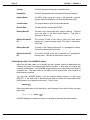
are individually numbered to make it easier to find information. To help you know where
you are at all times, the top of each even-numbered page contains a section number, a
chapter number, and a page number. For example:
Page 2
System Operator’s Guide, Rev. 00
Section 1 - Chapter 1
Page 2
Section 1 - Chapter 2
2.3Revision Information
The revisions of this manual are listed on the back of the title page. The last revision
number listed is the revision of the manual you have.
2.4Contents of this Book
This book is divided into the following major parts:
Section 1 Introduction
These chapters introduce you to this manual, explaining what
a System Operator is, what a System Operator does, and how
this book is organized.
Section 2 - System
Administration
The chapters in this section discuss how to allocate system
resources and what functions you can perform for system
users. You’ll learn to set up accounts and passwords, allocate
memory, attach terminals, see information about the status of
the system, implement "Technical Improvement Procedures,"
and distribute information to users on your system.
Section 3 - Disk
Maintenance
This section contains information on formatting and certifying
disks, on backing up disks on a variety of media, and on
running disk analysis programs. It also discusses how AMOS
handles bad disk blocks.
Section 4 - System
Configurations
The major topic of this section is a set of procedures for adding
new devices to the system. We discuss when and how to
configure disk drivers, how to convert a secondary disk device
into the System Disk, how to install a print spooler, and how to
generate a new terminal driver.
Section 5 Hardware Devices
This section describes those hardware devices that require
software set-up and maintenance.
Section 6 Appendices
This section contains useful tables and information.
Section 7 Glossary and Index
The Glossary provides definitions of terms used in this manual
that might be unfamiliar to you. The Index lists page numbers
where information on terms and names may be found.
System Operator’s Guide, Rev. 00
How to Use this Book
Page 3
2.5Reader’s Comments Form
We are always interested in providing you with the best manuals we can, and welcome
your comments and suggestions. The last page of this manual is a Reader’s Comment
Form. Please take time to fill it out and let us know if there are ways we can improve
future versions of this or any other Alpha Micro manual.
2.6Graphics Conventions
This manual conforms to the other Alpha Micro publications in its use of a standard set
of graphics conventions. We hope these graphics simplify our examples and make
them easier for you to use.
Unless stated otherwise, all examples of commands are assumed to be entered at
AMOS command level. We do not show an AMOS prompt symbol in these examples.
The AMOS prompt defaults to a period (.), but may be set to any symbol or group of up
to 19 characters. See the SET reference sheet in your System Commands Reference
Manual for information on setting the AMOS prompt.
SYMBOL
MEANING
devn:
Device-Name. The "dev" is the three letter physical device code, and the
"n" is the logical unit number. Examples of device names are DSK0:,
DSK5:, WIN1:, and MTU0:. Usually, device names indicate disk drives,
but they can also refer to magnetic tape drives and video cassette
recorders.
filespec
File Specification. A file specification identifies a specific file within an
account. A complete filespec is made up of the devn:, the filename, the
file extension, and the project-programmer number. For example:
DSK0:ERSATZ.INI[1,4]
[p,pn]
This abbreviation represents an account on a disk you can store files and
data in. An actual disk account number looks like this: [100,2] or [1,4].
TEXT
Bold text in an example of user/computer communication represents the
characters you type.
TEXT
Text like this in an example of user/computer communication represents
the characters the computer displays on your terminal screen.
System Operator’s Guide, Rev. 00
Page 4
Section 1 - Chapter 2
SYMBOL
MEANING
In our examples, the keycap symbol appears whenever you need to
press a certain key on your terminal keyboard. The name of the key you
need to press appears inside the keycap symbol, like this: RETURN . If you
need to press the TAB key, you would see TAB , or the ESCAPE key,
ESCAPE . (Sometimes the ESCAPE key is labeled ESC or ALT MODE.)
KEY
{}
Braces are used in some examples to indicate optional elements of a command line. In the example:
DIR{/switch}
the braces tell you "/switch" is not a required portion of the command line.
/
The slash symbol precedes a command line switch or "option request."
For example:
DIR/WIDE:3 RETURN
This command requests a directory display of the disk account you are
currently logged into. The switch (/WIDE:3) indicates you want the
display to be three columns wide.
CTRL
^
/
KEY
This indicates a control sequence you press on the keyboard. The
key is pressed and held down while the indicated key is also pressed.
CTRL
This symbol in front of a capital letter means the letter is a "control
character." For example, when you press CTRL / C , it appears on your
screen as ^C. (^C is the control character used like the CANCEL key to
cancel most programs and return you to AMOS command level.)
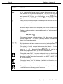
This symbol means "halt!" It indicates an important note you should read
carefully before going further in the documentation. Usually, text next to
this symbol contains instructions for something you MUST or MUST NOT
do, so read it carefully.
This symbol means "hint." It indicates a helpful bit of information, or a
"short cut" that could save you time or trouble.
This symbol means "remember." It indicates something you should keep
in mind while you are following a set of instructions.
System Operator’s Guide, Rev. 00
SECTION 2
SYSTEM ADMINISTRATION
This section contains information about many of the things you as the System Operator
need to know to set up and maintain your computer system.
System Operator’s Guide, Rev. 03
Section 2
SECTION 2
TABLE OF CONTENTS
CHAPTER ONE USER NAMES
1.1
1.2
1.3
1.4
1.5
The List of Valid User Names . . . . . . . . . . . . . . . . . . . . . . . . . . . . . . . .
Adding Users to the System . . . . . . . . . . . . . . . . . . . . . . . . . . . . . . . . .
Choosing User Names . . . . . . . . . . . . . . . . . . . . . . . . . . . . . . . . . . . . .
Assigning Root Accounts . . . . . . . . . . . . . . . . . . . . . . . . . . . . . . . . . . .
Logging on Using User Names . . . . . . . . . . . . . . . . . . . . . . . . . . . . . . .
1
1
2
2
2
CHAPTER TWO DISK ACCOUNTS AND PASSWORDS
2.1 Building a Disk Account Structure . . . . . . . . . . . . . . . . . . . . . . . . . . . . .
2.2 The SYSACT Command . . . . . . . . . . . . . . . . . . . . . . . . . . . . . . . . . . . .
2.3 An Example of Setting up Accounts . . . . . . . . . . . . . . . . . . . . . . . . . . .
1
1
2
CHAPTER THREE USER PROTECTION LEVELS
3.1 Changing Protection . . . . . . . . . . . . . . . . . . . . . . . . . . . . . . . . . . . . . . .
2
CHAPTER FOUR DISTRIBUTING INFORMATION TO USERS
4.1
4.2
4.3
4.4
4.5
4.6
The SEND Command . . . . . . . . . . . . . . . . . . . . . . . . . . . . . . . . . . . . . .
Sending a Message to More than one User . . . . . . . . . . . . . . . . . . . . .
Sending Messages to Other Computers . . . . . . . . . . . . . . . . . . . . . . . .
The HELP Command . . . . . . . . . . . . . . . . . . . . . . . . . . . . . . . . . . . . . .
The MAIL.JNK File . . . . . . . . . . . . . . . . . . . . . . . . . . . . . . . . . . . . . . . .
AlphaMAIL . . . . . . . . . . . . . . . . . . . . . . . . . . . . . . . . . . . . . . . . . . . . . .
1
2
2
2
3
3
CHAPTER FIVE SYSTEM INFORMATION COMMANDS
5.1 ATTACH . . . . . . . . . . . . . . . . . . . . . . . . . . . . . . . . . . . . . . . . . . . . . . . .
5.2 BITMAP . . . . . . . . . . . . . . . . . . . . . . . . . . . . . . . . . . . . . . . . . . . . . . . .
5.3 DATE . . . . . . . . . . . . . . . . . . . . . . . . . . . . . . . . . . . . . . . . . . . . . . . . . .
5.4 DEVTBL . . . . . . . . . . . . . . . . . . . . . . . . . . . . . . . . . . . . . . . . . . . . . . . .
5.5 ERSATZ . . . . . . . . . . . . . . . . . . . . . . . . . . . . . . . . . . . . . . . . . . . . . . . .
5.6 FREE . . . . . . . . . . . . . . . . . . . . . . . . . . . . . . . . . . . . . . . . . . . . . . . . . .
5.7 HELP . . . . . . . . . . . . . . . . . . . . . . . . . . . . . . . . . . . . . . . . . . . . . . . . . .
5.8 JOBALC . . . . . . . . . . . . . . . . . . . . . . . . . . . . . . . . . . . . . . . . . . . . . . . .
5.9 JOBPRI . . . . . . . . . . . . . . . . . . . . . . . . . . . . . . . . . . . . . . . . . . . . . . . .
5.10 JOBS . . . . . . . . . . . . . . . . . . . . . . . . . . . . . . . . . . . . . . . . . . . . . . . . . .
5.11 MAP . . . . . . . . . . . . . . . . . . . . . . . . . . . . . . . . . . . . . . . . . . . . . . . . . .
5.12 MEMORY . . . . . . . . . . . . . . . . . . . . . . . . . . . . . . . . . . . . . . . . . . . . . .
System Operator’s Guide, Rev. 03
1
1
2
2
2
2
2
2
2
3
3
3
Page 2
Section 2
5.13
5.14
5.15
5.16
5.17
5.18
5.19
5.20
5.21
PPN . . . . . . . . . . . . . . . . . . . . . . . . . . . . . . . . . . . . . . . . . . . . . . . . . . .
QUEUE . . . . . . . . . . . . . . . . . . . . . . . . . . . . . . . . . . . . . . . . . . . . . . . .
SET . . . . . . . . . . . . . . . . . . . . . . . . . . . . . . . . . . . . . . . . . . . . . . . . . . .
STAT . . . . . . . . . . . . . . . . . . . . . . . . . . . . . . . . . . . . . . . . . . . . . . . . . .
SYSLOG . . . . . . . . . . . . . . . . . . . . . . . . . . . . . . . . . . . . . . . . . . . . . . .
SYSTAT . . . . . . . . . . . . . . . . . . . . . . . . . . . . . . . . . . . . . . . . . . . . . . .
SYSTEM . . . . . . . . . . . . . . . . . . . . . . . . . . . . . . . . . . . . . . . . . . . . . . .
TIME . . . . . . . . . . . . . . . . . . . . . . . . . . . . . . . . . . . . . . . . . . . . . . . . . .
TRMDEF . . . . . . . . . . . . . . . . . . . . . . . . . . . . . . . . . . . . . . . . . . . . . . .
3
3
3
4
4
4
4
4
4
CHAPTER SIX HOW TO CREATE HELP FILES
6.1 Menu Help Files . . . . . . . . . . . . . . . . . . . . . . . . . . . . . . . . . . . . . . . . . .
6.2 Commonly Used TCRT Codes . . . . . . . . . . . . . . . . . . . . . . . . . . . . . . .
2
3
CHAPTER SEVEN WHAT IS A DRIVER PROGRAM
7.1
7.2
7.3
7.4
Definition of a Driver . . . . . . . . . . . . . . . . . . . . . . . . . . . . . . . . . . . . . . .
How to Make a Disk Driver . . . . . . . . . . . . . . . . . . . . . . . . . . . . . . . . . .
Physcial Units Versus Logical Devices . . . . . . . . . . . . . . . . . . . . . . . . .
Disk Formats . . . . . . . . . . . . . . . . . . . . . . . . . . . . . . . . . . . . . . . . . . . . .
1
2
3
3
CHAPTER EIGHT EVENT LOGGING
8.1
8.2
8.3
8.4
8.5
The LOGGER Program . . . . . . . . . . . . . . . . . . . . . . . . . . . . . . . . . . . . .
CPU Time . . . . . . . . . . . . . . . . . . . . . . . . . . . . . . . . . . . . . . . . . . . . . . .
Creating a File Listing the System Log . . . . . . . . . . . . . . . . . . . . . . . . .
Maintaining the Log File . . . . . . . . . . . . . . . . . . . . . . . . . . . . . . . . . . . .
Sending a Message to the Log . . . . . . . . . . . . . . . . . . . . . . . . . . . . . . .
1
2
2
2
2
CHAPTER NINE SETTING UP FUNCTION KEYS
9.1 Multiple Function Key Translation Tables . . . . . . . . . . . . . . . . . . . . . . .
9.2 Building the Function Key Translation Module . . . . . . . . . . . . . . . . . . .
9.3 Making a Translation Table Work . . . . . . . . . . . . . . . . . . . . . . . . . . . . .
1
1
3
CHAPTER TEN DEFINING ERSATZ DEVICE NAMES
10.1 How to Define an Ersatz Name . . . . . . . . . . . . . . . . . . . . . . . . . . . . . .
10.2 How to Use Ersatz Names . . . . . . . . . . . . . . . . . . . . . . . . . . . . . . . . .
1
2
CHAPTER ELEVEN LANGUAGE DEFINITION FILES
11.1 Setting up the Language Definition Files . . . . . . . . . . . . . . . . . . . . . .
11.2 Selecting a Language for Your Job . . . . . . . . . . . . . . . . . . . . . . . . . . .
11.3 Defining Your own Language Definition Files . . . . . . . . . . . . . . . . . . .
1
2
2
CHAPTER TWELVE PATCHING PROGRAMS
12.1 The PATCH Process . . . . . . . . . . . . . . . . . . . . . . . . . . . . . . . . . . . . . .
1
System Operator’s Guide, Rev. 03
Table of Contents
Page 3
CHAPTER THIRTEEN THE DISK CACHE BUFFER MANAGER
13.1
13.2
13.3
13.4
13.5
Theory of the Disk Cache . . . . . . . . . . . . . . . . . . . . . . . . . . . . . . . . . .
The Programs Making up the Disk Cache System . . . . . . . . . . . . . . .
Setting Up the Cache . . . . . . . . . . . . . . . . . . . . . . . . . . . . . . . . . . . . .
Displaying Information About the Cache . . . . . . . . . . . . . . . . . . . . . . .
How to Make the Cache Most Efficient on Your System . . . . . . . . . .
1
2
2
3
3
CHAPTER FOURTEEN THE VIRTUAL DISK
14.1 How to Set Up the Virtual Disk . . . . . . . . . . . . . . . . . . . . . . . . . . . . . .
14.2 When Is the Virtual Disk Used? . . . . . . . . . . . . . . . . . . . . . . . . . . . . .
1
2
CHAPTER FIFTEEN FINDING INFORMATION IN ALPHA MICRO DOCUMENTATION
15.1 Where Do I Start? . . . . . . . . . . . . . . . . . . . . . . . . . . . . . . . . . . . . . . . .
15.2 Where to Look . . . . . . . . . . . . . . . . . . . . . . . . . . . . . . . . . . . . . . . . . . .
System Operator’s Guide, Rev. 03
1
1
SECTION 2 - CHAPTER 1
USER NAMES
Each user on the computer is given a unique user name. When the user logs in, AMOS uses
the information associated with the user name to tailor system access and privileges to the
user. As of AMOS 2.0 and later, user names are required for all system users. As the System
Operator, you’ll have to create and maintain the list of valid user names.
In this document, we discuss how you define each user. We cover the USER.SYS file, the
MUSER program, and the LOG and LOGON commands.
1.1The List of Valid User Names
Every user is identified by a unique user name and defined in the list of valid user
names. When the user logs in, he or she enters a user name when prompted to do so.
AMOS checks this user name against the list of valid user names. If valid, the user is
logged in to an account. In the meantime, the user’s environment is set up according to
the user definition.
The list of valid user names is stored in the file DSK0:USER.SYS[1,2]. You do not deal
with this file directly. Instead, the menu-driven MUSER program you’ll be using to
define user names will store and retrieve information for you. See the MUSER reference sheet in your System Commands Reference Manual for information.
Your AMOS release tape has an initial USER.NEW file defining the user name System
Service which can be used to log in to DSK0:[1,4] during the initial setup period. If you
don’t have a USER.SYS already defined on your system, rename USER.NEW to
USER.SYS. Then enter:
LOG SYSTEM SERVICE RETURN
There is also a User Name, Demo for initial use.
1.2Adding Users to the System
There are three things you must do to add a new user to the system:
Choose a unique user name for the user.
Decide on and allocate a root account and one or more disk accounts for
the user using the SYSACT program.
System Operator’s Guide, Rev. 00
Page 2
Section 2 - CHAPTER 1
Enter the user definition using the MUSER program.
The root account and the user definition will become clearer to you as we discuss these
points in the next section.
1.3Choosing User Names
User names may contain up to 20 characters from the set of printable ASCII characters,
including spaces. Lower case letters are different from upper case, but are compared
independent of case. The first character must be a letter. First and last names, job
titles, and project names are often used as user names. You may not use the following
characters in a user name:
[
]
,
1.4Assigning Root Accounts
Everyone needs a central storage place for private use. This is what a root account is
for. A user’s root account distinguishes the user personally, apart from the many project
accounts this person may have. Office support applications may send messages,
results, and reminders to a user’s root account.
The root account you assign to the user is identified in the same way as any disk
account—by its device name and account number. For example, you might assign
DSK7:[211,0] as the root account for Jane Doe. Accounts DSK7:[211,10] and
DSK7:[211,11] would then be her project accounts.
See Section 2 - Chapter 2 for more about disk accounts and passwords.
1.5Logging on Using User Names
There are two ways to log on to the system from a logged out state. You may use the
conversational LOGON program or you may sign on with the LOG command.
The LOGON program displays a menu request for your user name. When you enter
your user name (and, if needed, your user password), you are automatically logged in to
your root account.
See the LOGON and LOG reference sheets in your System Commands Reference
Manual.
System Operator’s Guide, Rev. 00
SECTION 2 - CHAPTER 2
DISK ACCOUNTS AND PASSWORDS
The users on your system will need to have disk accounts in which they can work. Some of
these disk accounts may require security, or limited access. This document explains how to set
up and manage disk accounts.
2.1Building a Disk Account Structure
Your disk must be initialized before accounts can be set up—if your
disk has not yet been initialized, see the SYSACT reference sheet in
your System Commands Reference Manual for instructions.
All files on a disk are associated with an account on that disk. Usually, you may not
write any files to the disk until a user account exists to hold those files. However, you
can copy files onto an initialized disk with no account structure if you copy from the
System Operator’s account, [1,2]. In this case, the COPY command allocates the
proper accounts for you on the new disk as it copies over the files.
You can only access a file if you log into the account which contains the file or if you
specify the account the file belongs to in that file’s specification.
Each account on the disk has a directory associated with it (called a User File Directory
or UFD) listing the files in that account. Every disk has one Master File Directory (called
the MFD) that maintains a list of all UFDs on that disk. When you first initialize a disk,
SYSACT creates the MFD on the disk, but no UFDs exist. As you use SYSACT to
allocate user accounts, SYSACT creates the UFDs for those accounts.
2.2The SYSACT Command
The SYSACT command allows you to do several disk maintenance functions. You may
use SYSACT to:
Initialize a disk (clear and prepare it for use)
Allocate user accounts on a disk
Change account passwords
Delete user accounts
System Operator’s Guide, Rev. 00
Page 2
Section 2 - Chapter 2
Display a list of accounts and passwords on a disk.
For details on the use of the SYSACT command, see the SYSACT reference sheet in
your System Commands Reference Manual.
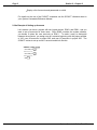
2.3An Example of Setting up Accounts
Let’s assume you have a system with two logical devices, DSK0: and DSK1:, and you
want to set up accounts for three users. Since DSK0: contains the system software,
you decide to place the user accounts on DSK1:. To make it easy to distinguish
between the accounts, you assign user #1 accounts beginning with the project number
of 100, user #2 accounts in project 200, and user #3 accounts in project 300. The
SYSACT entries to set up user #1’s account would look like this:
SYSACT DSK1: RETURN
* A 100,0 RETURN
Password:
* A 100,1 RETURN
Password:
* E RETURN
System Operator’s Guide, Rev. 00
SECTION 2 - CHAPTER 3
USER PROTECTION LEVELS
AMOS 2.0 and later releases provide a method to protect disk files. Using this feature of User
Protection Levels, individual files may be coded for different kinds of access. The level of
protection dictates who can do what with the file.
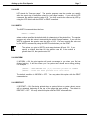
All files on the system have a protection level. This file protection takes the form of a ten-digit
code number associated with each directory (disk account) and file. This code number is made
up of five groups of two digits each.
Each two digit group specifies the protection level for a certain class of user trying to access the
file. AMOS automatically determines the class of the user, and accesses the appropriate group
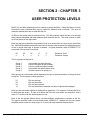
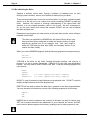
of bits to decide what type of access is allowed. A typical protection code of 0505051717 is
composed of five groups of two digits:
05
5
05
4
05
3
17
2
17
1
Protection Code
Protection Groups
The five groups correspond to:
Group 1
Group 2
Group 3
Group 4
Group 5
Users within the same directory
Users in the same project number
Users in a different project number
Users within the same network level
All other users not in groups 1-4
Each group is an octal number which represents the type of access members of the group have
to that file. The four basic number codes are:
01
02
04
10
File may be read
File may be written
File may be executed
File may be deleted, renamed, and have its protections changed
Note you can add codes together to combine their properties. For example, 03 allows the file to
be both read and written. A code of 06 allows the file to be both written and executed. And a
code of 17 combines all the access types into one.
Each of the five groups defined above can have different combinations of access to the file.
The typical protection code we mentioned earlier, 0505051717, enables the first two groups
complete access to the file, while groups 3, 4, and 5 can only read and execute the file.
System Operator’s Guide, Rev. 02
Page 2
Section 2 - Chapter 3
An interesting sidelight to this scheme of protection codes is if a particular group does not have
"read" access to the file (a code of 00, for example), the file will not appear on any directory
displays requested by members of that group—it is essentially invisible to them.
The only access type that can be overridden is 10 (delete, rename). The System Operator, by
logging into OPR: (the System Operator’s account, DSK0:[1,2]), can delete and rename files
that would otherwise be inaccessible.
If the ten digit protection code is preceded by a "1", it indicates the file should be "zeroed" when
it is erased. The sample code above would become 10505051717. Normally, erased files are
simply removed from the directory, but the data in the file is left intact on the disk. If this "Zero
Flag" is present, the file will be removed from the directory, and the data blocks which once
comprised the file will be filled with zeros, thus obliterating the data.
3.1Changing Protection
The RENAME command allows you to change the protection of the files for which you
have "write" access. Since RENAME is a wildcard command, you can change the
protection of an entire group of files or change one file at a time. The /PROTECTION:
(or /PROT:) switch, followed by the new protection code, updates the file protection
code in addition to whatever else you ask RENAME to do. For example:
RENAME CUSTMR.SAV/D=CUSTMR.LST/PROT:10001010317 RETURN
The command above renames CUSTMR.LST to CUSTMR.SAV (and deletes the
existing CUSTMR.SAV file), and it gives CUSTMR.SAV the new protection code
10001010517. This code can be interpreted like this: 10001010517. The first digit is
the "zero flag" indicating the data will be overwritten with zeros when it’s erased. The
next group, "00," indicates group 5 has absolutely no access to the file. Groups 3 and 4
are only allowed to read the file, group 2 can read and write the file, and group 1
(anyone who can login to the account where the file resides) can do anything they want
to it.
RENAME can also be used just to change protection like this:
RENAME DATA.S87/PROT:0303030717 RETURN
Keep in mind protection is only available under extended directories. The DIR program
(and others) shows the default protection 0505051717 for all files under the traditional
directory format since that is the equivalent protection code.
System Operator’s Guide, Rev. 02
SECTION 2 - CHAPTER 4
DISTRIBUTING INFORMATION
TO USERS
This chapter discusses:
The SEND command, which allows you to send messages to users.
The HELP command, which allows you to set up HELP files.
The MAIL.JNK file, which allows you to have a message display when users log in.
The AlphaMAIL product, which allows you to send permanently stored messages.
The AlphaNET product, which allows you to connect Alpha Micro computers
together in a network in order to exchange messages and data.
4.1The SEND Command
The quickest way to contact a specific user of the system is to use the SEND command.
Type SEND, the user’s job name, your message, and press RETURN . For example:
SEND TERM1 Your report has finished printing. RETURN
TERM1 will then see:
;SYSOP - Your report has finished printing
Notice you can use both upper and lower case letters when you write the message.
The message is sent when you press RETURN . There are a few cases when the message
will not get through— if so, you will see: ?Busy.
System Operator’s Guide, Rev. 00
Page 2
Section 2 - Chapter 4
4.2Sending a Message to More than One User
To send a message to all the jobs on your system, place an asterisk after SEND and
before your message:
SEND * Gather in main conference room at ten RETURN
If you regularly send messages just to certain people, you can create a command file for
the purpose.
4.3Sending Messages to Other Computers
If your computer has an AlphaNET connection to other computers, you can send
messages to users on those computers by specifying a CpuID. For example:
SEND 1562758- JACK Did you get my report?
To make CpuIDs easier to specify, you can define an Ersatz name—see Section 2 Chapter 10.
4.4The HELP Command
Your system comes equipped with special text files in the system Help File Library,
DSK0:[7,1]. These files all have the extension .HLP and contain information on various
system features.
To look at a specific .HLP file, enter HELP and the name of the topic you would like help
on. For example:
HELP SYSTAT RETURN
The file HELP.HLP originally contains a list of the help topics included with AMOS. You
can create your own help files, and change or edit HELP.HLP, to provide whatever
helpful information the users on your system may need. They can then see the
appropriate .HLP screens whenever they need assistance.
If there are certain topics only for certain jobs or accounts, you can also place .HLP files
in your project library account, [your-project-#,0]. When you ask to see a .HLP file,
AMOS first looks in the system Help Account, then in your project library account and
finally in the account you are logged into. If there is no .HLP file on the topic you want,
you see this message: Unable to locate help file.
For information on creating your own help files, see Section 2 - Chapter 6.
System Operator’s Guide, Rev. 00
Distributing Information to Users
Page 3
4.5The MAIL.JNK File
The LOG program will search for a file, DSK0:MAIL.JNK[7,2]. If the file exists, it will
display the first line of it on a user’s terminal when that user logs in to the system (but
not when LOG is used merely to go from one account to another).
This is a handy way to bring some matter to the attention of all of the users on your
system when they first log in.
4.6AlphaMAIL
AlphaMAIL is designed to make it easy to send people electronic messages. It is a
sophisticated, menu-driven program allowing you to easily create and distribute text
messages, memos, letters, etc., to one or more people on your system (or even, using
communication networks, other computer systems). If you have the AlphaMAIL product
on your system, you can call it up by entering "MAIL" at AMOS command level, and
then you will see a menu allowing you access to all of AlphaMAIL’s features. For a
complete description of how to use AlphaMAIL, see your AlphaMAIL User’s Guide.
System Operator’s Guide, Rev. 00
SECTION 2 - CHAPTER 5
SYSTEM INFORMATION COMMANDS
As the System Operator, you have many specialized duties to perform. To aid you in your use
of the Alpha Micro system, we provide a number of system information commands which are
designed to make your job easier. They are:
ATTACH
FREE
MAP
STAT
TRMDEF
BITMAP
HELP
MEMORY
SYSTAT
DATE
JOBALC
PPN
SYSLOG
DEVTBL
JOBPRI
QUEUE
SYSTEM
ERSATZ
JOBS
SET
TIME
This chapter summarizes these commands and introduces you to their most useful features.
Many of the commands can be used in your system initialization command file as well as at
AMOS command level. You can find out more about their use in the system initialization
command file by reading your System Operator’s Guide to The System Initialization Command
File. These commands are described fully in your System Commands Reference Manual.
5.1ATTACH
The ATTACH command displays which terminals are attached to which jobs in your
system, and lets you attach a terminal to a different job than the one it is already
attached to.
When you reset or power up your system, your system initialization command file
automatically attaches the first job to the first terminal. To attach other terminals to
other jobs, you must use the ATTACH or SETJOB command in the system initialization
command file.
5.2BITMAP
The BITMAP command is used in the system initialization command file to define the
disk bitmap areas used by the operating system. You can use BITMAP at AMOS
command level to find out what memory locations are used by these bitmaps.
System Operator’s Guide, Rev. 00
Page 2
Section 2 - Chapter 5
5.3DATE
DATE displays the current date. From OPR: you may change the system date.
5.4DEVTBL
DEVTBL displays the devices defined on your computer.
5.5ERSATZ
ERSATZ displays the currently set ersatz names.
5.6FREE
FREE displays the number of free blocks and the largest contiguous free space.
5.7HELP
Displays text files on your terminal containing information about the system. HELP can
both list all the .HLP files available and display a specific .HLP file for you. A .HLP file
library resides on DSK0:[7,1] (HLP:), but if HELP can’t find the file you’re looking for
there, it looks in your project library account, and finally looks on the device and account
you are currently logged into.
A variety of .HLP files come with your system, and you can add .HLP files to the library
account for your own topics. For information on creating help files, see Section 2 Chapter 6.
5.8JOBALC
In your system initialization command file, JOBALC assigns and names the jobs the
system will use. You can also use it at AMOS command level to display your job name.
5.9JOBPRI
The JOBPRI command allows you to determine the priority of your job, to change your
job’s priority, and to examine and change the priorities of other jobs. The priority of a
job determines the amount of time the computer spends on it before processing another
job. The maximum priority is 254; the minimum is 1. The default is 13.
System Operator’s Guide, Rev. 00
System Information Commands
Page 3
5.10JOBS
Used in your system initialization command file, the JOBS command defines the
number of jobs that can run on your system. Used at AMOS command level, JOBS tells
you how many jobs have been allocated and how many have been assigned.
5.11MAP
MAP shows you what programs are loaded into your memory partition. Each file is
listed with the number of bytes, its address in memory, and an identifying hash total.
Also listed is the number of "free" or unused bytes in your memory partition.
5.12MEMORY
The MEMORY command allocates memory to your job, or displays how much memory
is currently allocated to your job.
5.13PPN
The PPN command shows you a list of all the project-programmer numbers associated
with the accounts on any logical device you specify.
5.14QUEUE
The QUEUE command is used in your system initialization command file to increase the
size of your monitor queue beyond its initial size of 20 eight-word blocks. At AMOS
command level you can use the QUEUE command to find out how many queue blocks
are available.
5.15SET
The SET command has a wide variety of uses. You can use it at AMOS command level
to select or suppress network access, system language, Control-C interrupts, disk error
reporting, terminal echoing, printing forms, terminal guarding, program function key
translation, the AMOS prompt, terminal attributes, and other features.
These options are only set for the job that used the SET command. SET alone will
display the options currently set.
System Operator’s Guide, Rev. 00
Page 4
Section 2 - Chapter 5
5.16STAT
STAT displays the jobs on your system, and continually updates their status. The STAT
display continues to update itself until you press CTRL / C or ESC and Q .
5.17SYSLOG
SYSLOG creates a list of the events logged by the event logging system (if your
computer has the event logging system installed). Its summary gives the total number
of times each event type occurred, the average time between system restarts (average
uptime), and the system availability as a percentage of the total time covered by the
report. See Section 2 - Chapter 8, "The Event Logging System" for more information.
5.18SYSTAT
SYSTAT lists the jobs on your computer and their status.
5.19SYSTEM
As part of your system initialization command file, SYSTEM tells the operating system
what programs to include in system memory. At AMOS command level, SYSTEM tells
you what programs currently reside in system memory.
5.20TIME
TIME sets or displays the time of day.
5.21TRMDEF
TRMDEF displays what terminals are defined on your computer. The display lists the
terminal name, the name of the job it is attached to, the address in memory where the
Terminal Definition Block for that terminal is located, the interface driver used by the
terminal, the number of the port on the I/O board the terminal is attached to, the terminal
driver used by the terminal, and the terminal parameters.
System Operator’s Guide, Rev. 00
SECTION 2 - CHAPTER 6
HOW TO CREATE HELP FILES
AMOS comes with a set of HELP files in DSK0:[7,1] that can be accessed by any user from
AMOS command level. These files contain a brief summary of common AMOS commands.
You can provide further help to the users on your system by creating your own HELP files.
A HELP file is a disk file with a .HLP extension. The HELP command searches for a file of the
name you supply, and defaults to an .HLP extension. For example, if you enter:
HELP INVENT RETURN
HELP looks for a file called INVENT.HLP, first in the HLP: account (DSK0:[7,1]), then in your
[P,0] account, and finally in your current account. It then displays it on the terminal screen, one
screen-page at a time.
A HELP file is not much different from a regular disk file you print on paper. The only difference
is in how the file is displayed. Because a terminal screen is smaller than a sheet of paper, your
page layout will be different. And you can (if you wish) use the terminal’s ability to display
different attributes, such as reverse video, dim text, etc. Just what you will be able to display
will depend on what type of terminal you have.
You may use either the AlphaVUE text editor, or the AlphaWRITE word processing system to
create HELP files.
Create a text file as you normally would, and enter the information you want to have displayed.
You may want to look at the AMOS HELP files for an example of screen layout. The HELP
program automatically stops at the end of a screen "page." The length of the screen page will
depend on your terminal type, so count the number of lines your terminal will display. You can
then tailor your screen "pages" to your terminal for easy viewing.
Then format the file to create a .LST file. If you don’t need to use screen attributes, you can
rename this .LST file to .HLP, and use HELP to display it.
If you want to highlight your text with display attributes, you can choose from the abilities your
terminal will support (see the manual that came with your terminal), and edit the .LST file to add
the attributes. If you used AlphaWRITE to create the .LST file, you will have to use AlphaVUE
from this point on. The procedure is:
1.Place the cursor at the point in your text where you want the attribute to begin.
2.Press
CTRL
/
G
and then
System Operator’s Guide, Rev. 00
ESC
.
Page 2
Section 2 - Chapter 6
3.Now type in the number of the TCRT code for the attribute you wish. The AMOS
Terminal Programmers Manual contains a complete list of TCRT codes.
AlphaVUE has a HELP file listing TCRT codes.
4.Place the cursor at the place in your text where you want the attribute to end.
5.Press
CTRL
/
and then
G
ESC
.
6.Now type in the number of the TCRT code that turns off the attribute.
You will see symbols and numbers in your text.
attribute by the HELP program.
These will be translated into the proper
6.1Menu Help Files
You can also design help files that call other help files in response to user input. This
allows you to have multi-level help files that cover broad areas of information and
allowing users to see only the information pertinent to their needs. You do this by
associating help file specifications with numbers. A left brace, {, begins the definitions,
and a right brace, }, ends the definitions (the text of which will not be displayed on the
screen). For example:
{
1=TAX.HLP
2=FILE.HLP
3=INVEN.HLP
}
TAX DATABASE HELP
Type the number of the subject you wish help for:
1 - Tax Rates
2 - Keeping the Tax File updated
3 - Using the Inventory list in Depreciation
computations.
When the file above is accessed, you’ll see the above display (without the definition
part), and then you can press 1, 2, or 3 to see the appropriate help file. If you press
CTRL /
C
or CANCEL , you will return to AMOS command level. If you press MENU or ESC
ESC , you will be returned to the last help file level.
As you can see, you can build a structure of interlocking help files of whatever depth
you need.
System Operator’s Guide, Rev. 00
How to Create Help Files
6.2Commonly Used TCRT Codes
0
11
12
21
22
23
24
30
31
32
33
34
35
Clear Screen and set normal intensity
Enter Background Display Mode (reduced intensity)
Enter Foreground Display Mode (normal intensity)
Start Blinking Field
End Blinking Field
Start Line Drawing Mode (enable alternate character set)
End Line Drawing Mode (disable alternate character set)
Start Underscore
End Underscore
Start Reverse Video
End Reverse Video
Start Reverse Blink
End Reverse Blink
System Operator’s Guide, Rev. 00
Page 3
SECTION 2 - CHAPTER 7
WHAT IS A DRIVER PROGRAM?
One important feature of all Alpha Micro computer systems is the ability to quickly and easily
interface a new type of device to the computer by making a few modifications to the system
software. Section 4 - Chapter 1 discusses how to do this.
However, before you get into that kind of installation, it is a good idea to become familiar with
some of the basic concepts—how the monitor communicates with devices in general and disk
drives in particular.
This chapter discusses how disk drivers work, and how to use them, and gives some background information on other disk-related concepts. In addition, it discusses the physical format
of a disk.
7.1Definition of a Driver
A disk driver is one member of the general family of programs called "device drivers."
Such a program must be in account DSK0:[1,6] (DVR:).
Terminal drivers (programs linking the generalized terminal handling routines of the
monitor to user terminals) have .TDV file extensions.
Interface drivers (programs handling character translation through the Input/Output controller the terminals are physically connected to) have .IDV extensions.
You will see programs with .PDV and .MDV extensions—these are special printer and
modem drivers. The .PDV files are printer drivers for application programs like
AlphaWRITE and AlphaCALC.
Disk drivers have .DVR extensions (as do other types of device drivers such as
magnetic tape transport drivers, and video cassette recorder drivers). The disk driver
allows the disk service routines of the monitor to communicate with the actual disk drive.
The monitor cannot communicate directly with the devices connected to the computer
because each device has its own peculiarities and needs and, in order to preserve the
device-independent nature of the monitor, the monitor input/output routines must remain
generalized.
System Operator’s Guide, Rev. 00
Page 2
Section 2 - Chapter 7
You can think of the disk driver as an entity that translates general monitor functions
(such as "read a block of data") into more specialized actions ("go to THIS sector and
THAT track, and read THIS data") suited to the particular drive the monitor is
communicating with.
How does the monitor know which disk driver to use for which disk? When you define a
device to the monitor (by adding a device definition to the system initialization command
file), the three-character name you assign to the device is the name of the driver to be
used to access that device.
For example, if you want to access a disk defined as PLD0:, then the monitor uses the
driver DSK0:PLD.DVR[1,6] to communicate with it.
The single exception to this is the case of the System Device. The System Device is
the drive from which the system boots, and is always named DSK even though there is
no disk driver named "DSK." We discuss the special case of the System Disk in Section
4 - Chapter 3.
Alpha Micro supplies disk drivers in account DSK0:[1,6]: for all of the disks we sell, and
many others we support. The name of the disk driver program reflects the type of
device it applies to. For example, 515DVR.DVR is a driver program for an AM-515
controlled disk device. You can use the AMOS DIR program in account DSK0:[1,6] to
see the available driver programs.
7.2How to Make a Disk Driver
Disk drivers have six-character names representing the type of disk they handle. If you
install a peripheral disk drive you will need to choose a three-character name for the
new device.
In the case of floppy disks, you will need to use either the FIXFLP or FIX210 program to
make a new driver for that subsystem. See Section 4 - Chapter 6.
In the case of non-self-configuring Winchester disks, you will need to use the FIX420
program to make a driver.
Self-configuring Winchester disks use a standard driver, without need for a customized
driver. This is true regardless of the size of the disk involved. For more information,
see Section 4 - Chapter 7.
With either the floppy or non-self-configuring Winchester disks, the new driver will bear
the three-character name you have chosen. You can then add this three-character
name to the DEVTBL and BITMAP statements in your system initialization command file
to define the device to your system.
System Operator’s Guide, Rev. 00
What is a Driver Program?
Page 3
If you wish to configure a disk as the System Device, you will need to do some other
procedures after having first defined the device as a peripheral disk. See Section 4 Chapter 1 for specific information on adding a new disk drive to the system, and Section
4 - Chapter 4 for information on changing that peripheral disk to a System Disk.
7.3Physical Units Versus Logical Devices
Many of the documents in this book mention the terms "physical unit" and "logical
device." You will need to understand the difference between these two concepts before
you begin formatting and initializing disks.
A physical unit (or "physical device") is the actual hardware disk drive—the unit
containing the actual magnetically sensitive disk and the read/write heads that record
and read back data in tracks on the disks.
A logical device (or "logical unit") is the definition of a physical unit in terms the monitor
can deal with. It is an abstraction serving to identify the structure of the physical unit to
the monitor. The computer cannot access or place data on the disk unless it has
available to it a name for the disk and file directories and bitmaps containing pointers to
the contents of the disk. So, while the disk might be a single Winchester drive to you,
the monitor sees that physical unit as logical devices such as DSK0:, DSK1:, and DSK2:.
Sometimes a physical unit contains only one logical device (for example a single drive
of a floppy disk subsystem might be identified as logical device DDA0:), and so we tend
to think of the logical device and the physical unit as being the same thing.
However, physical units in the Winchester technology family of disks can contain
multiple logical devices, demonstrating that while logical devices are closely related to
physical units, they are not precisely the same thing.
7.4Disk Formats
The "format" of a disk is the way the data on a disk is structured. This section discusses
both physical and logical disk formats.
The physical format means the number of bytes in each sector on the disk (which in turn
dictates the number of sectors on each track). The logical format refers to the way in
which the operating system reads the physical format, including the blocking factor and
file structuring.
We call the sector a physical record because it reflects the physical organization of
data on the disk. AMOS imposes a logical organization on the disk (regardless of the
physical attributes of the device); we call these logical units of data disk blocks.
Except in the special case of devices using the IMG device driver, disk blocks are
always 512 bytes long.
System Operator’s Guide, Rev. 00
Page 4
Section 2 - Chapter 7
For hard disk devices currently supported by Alpha Micro, the size of the disk block is
the same as the physical record size (512 bytes); floppy disk devices sometimes use a
physical record smaller than a disk block.
Before initial use, disk devices must be "formatted" or "certified" (depending on the type
of disk) to set the initial structure of the data on the disk. Most of the time, this is done
before you get the disk, so you don’t generally have to worry about it. Should you have
a need to format or certify a disk, the System Commands Reference Manual contains
information on various certification and formatting programs for the various types of
disks and devices.
System Operator’s Guide, Rev. 00
SECTION 2 - CHAPTER 8
EVENT LOGGING
The LOGGER and SYSLOG programs help you to extract a comprehensive log of your
computer’s activities. In this chapter, we discuss how to use this event logging system.
Set up at system initialization time, the LOGGER program performs the logging task in the
background, recording events that require special handling by your computer. When a special
event occurs, LOGGER records it in a disk file, along with the time, date, and other facts. You
can then use the SYSLOG program to read the disk file and produce a formatted listing,
summarizing all items recorded.
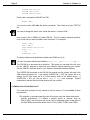
8.1The LOGGER Program
The event logging task runs as a background task, requiring one job dedicated to it
within the system. The task is started by forcing the LOGGER command line to the
background job in your system initialization file. To ask AMOS to run LOGGER in the
background, you must create a job (it needs at least 10K of memory), define a
pseudo-terminal for it, initialize the job, and declare there will be input forced into the
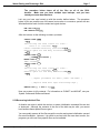
job. Then list the commands to be executed by the job. For example:
JOBALC LOGJOB
TRMDEF LOGTRM,PSEUDO,NULL,100,100,100
SETJOB LOGJOB,LOGTRM,10K,LOGCMD
where LOGCMD is a command file:
LOG SYSTEM SERVICE,
LOGGER 7
The 7 in this example sets the severity an event needs to have in order to be logged.
The higher this number is, the more events are recorded in the log file. 7 is generally a
good choice for this number; higher settings can record common events, such as
switching between accounts, and may slow the system down and cause the log file to
grow very quickly.
By default, events are logged in the OPR:SYSLOG.SYS file. You can specify a different
log file by putting a file specification at the end of the LOGGER command line.
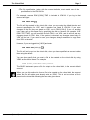
Do not modify the existing system initialization command file directly! First, make a copy
of it under a different name, modify the test copy, and Use MONTST to test it. See your
System Operator’s Guide to the System Initialization Command File for information.
System Operator’s Guide, Rev. 03
Page 2
Section 2 - Chapter 8
8.2CPU Time
Because the LOGGER program remains running in the background at all times, it does
consume a small amount of CPU time. However, it is generally less than .03% of the
total CPU time. A visible difference is seen, however, at the time an event is logged.
Because the event file must be updated, a slight pause may be seen during the event
itself. Since most events logged are system errors, this slight delay should be inconsequential. Any CPU time used by logging is charged to the job causing the event.
8.3Creating a File Listing the System Log
To create a list file (SYSLOG.LST) containing a chronological listing of all events logged
since the last time the log file was cleared, enter:
SYSLOG {logfile}{kcRETURN}
logfile is the name of the system log file you want to create a listing from, if you are not
using the default of SYSLOG.SYS. The output file is always OPR:SYSLOG.LST.
Each event is listed with its date and time of occurrence, along with any information
known about the particular event. SYSLOG also calculates and presents statistics to
summarize the report. This shows the total number of times each event type occurred,
the average time between system restarts (average uptime), and the system availability
as a percentage of the total time covered by the report.
8.4Maintaining the Log File
A typical event adds 18 bytes to the event log file SYSLOG.SYS. This file is extended
as long as disk space is available. Because the time to update the event file increases
as the size of the file increases, you should clear this file about once a month to
prevent the file from becoming too large. You may clear the contents of the log file only
from account DSK0:[1,2], where it resides. Enter:
SYSLOG/CLEAR RETURN
Section 6 - Appendix B contains a list of all the system events LOGGER records.
8.5Sending a Message to the Log
You may send a message to the system log using the AlphaBASIC XCALL MSGLOG.
With it, you can send a message text and a code of 1 to 999. The format is:
XCALL MSGLOG,TEXT,CODE,STATUS
See your AlphaBASIC XCALL Subroutine User’s Manual for more information.
System Operator’s Guide, Rev. 03
SECTION 2 - CHAPTER 9
DEFINING FUNCTION KEYS
The SET program gives you the ability to simulate programmable terminal function keys, even if
the function keys of your terminal are not programmable. In effect, you can redefine the data
sent by any terminal key that normally sends a two-character sequence.
This means you can redefine not only those keys we normally think of as function keys (keys
labeled F1, F2, etc.), but also any other special keys that send a two-character sequence. For
example, on the AM-60 terminal you can redefine the codes sent by such keys as PREV
WORD and NEXT SCREEN.
The technique AMOS uses to simulate function key programmability is to allow you to define a
function key translation module that resides in your user memory partition and through which
the operating system "filters" the codes sent by terminal keys. For example, a particular
function key may send an Escape-L sequence when pressed. Your function key translation
module may tell AMOS an Escape-L really means ERASE *.BAK RETURN DIR/W RETURN —or any
other string of characters you define.
9.1Multiple Function Key Translation Tables
You may define multiple function key translation modules for different applications.
Such modules when saved to disk may be renamed to any name (not necessarily the
name of the application with which you will use it), but must have the file extension .PFK
(programmed function key). You must load the proper translation module into memory
before using that application. AMOS will use the first .PFK module it finds in memory to
translate your terminal key output.
You must build a unique function key translation table for each different type of terminal,
since each terminal sends different function key codes. Thus a translation table built for
an AM-60 terminal will not work with a AM-70 terminal.
9.2Building the Function Key Translation Module
To create a .PFK module:
1.Log into the disk account in which you want to store the .PFK file.
2.Use the SET PFK command:
SET PFK RETURN
System Operator’s Guide, Rev. 00
Page 2
Section 2 - Chapter 9
If no .PFK file exists in your memory partition, SET creates a module
named FUNKEY.PFK. If an existing .PFK module of any name already
exists in memory, SET modifies it with any definitions you change or add.
3.SET now tells you:
Enter unique key to terminate input:.
Press whatever single key you want to use to tell SET you are finished
with a function key definition. It is not a good idea to use RETURN , since you
will most likely want to include a RETURN within your function key definition.
The most commonly used key for a terminator (since you will rarely want to
include it in a definition) is RUB (sometimes RUBOUT or DEL ). As you press
the key, SET echoes it to your screen. You may NOT use as a terminator
any key that sends a two-character sequence (for example, another
function key).
4.Next SET tells you: Press function key to be translated or X
to end definitions:, where "X" is the terminator key you pressed in
answer to the previous question. Press the key you wish to re-define (for
example, the F1 key). If you are through defining function keys, press the
terminator key you defined above. If the .PFK module in memory already
has a definition for the key you just pressed, SET displays the old
definition.
5.Now you see: Enter sequence to translate function key to,
terminated by X:, where "X" is the terminator character you previously
defined. Note if you enter the terminator character at this point, you will
erase any former definition.
Enter the sequence of characters you want to have sent to AMOS
whenever that function key is pressed. You must enter the characters
EXACTLY as you wish them sent—EVERY character you enter at this
point will be part of the key definition. This means you can’t edit your
definition, since a RUBOUT or Control-U will be entered as part of the key
definition. If you make a mistake typing, just start again.
The size of your terminal input buffer (defined within the system
initialization command file TRMDEF statement for your particular terminal)
determines the number of characters you may enter as a definition. For
example, if your input buffer is 100 bytes, you may enter 100 characters
(including special characters such as RETURN , CTRL / A , etc.).
When you are finished with the definition, press the previously defined
terminator key.
6.SET now asks for another function key. You can continue defining
function key translations until you have set up all the keys you want to
translate. When you are done, press just the terminator key to exit from
SET.
System Operator’s Guide, Rev. 00
Defining Function Keys
Page 3
7.Once you have exited from SET, an updated .PFK module will be in your
memory partition. If you wish to save this module permanently as a disk
file so it can be reloaded later, use the SAVE command:
SAVE FUNKEY.PFK RETURN
If you want the .PFK module to have a different name, you can save it to
the disk with SAVE, and then use the RENAME command to rename the
disk file, or you can rename it in memory first.
9.3Making a Translation Table Work
To make a particular function key translation table work, just load it into memory from
the disk. For example, if you are running an AlphaBASIC program named PAYROL and
want to use the function key translation module for that program saved on disk as
BASIC.PFK, you must load BASIC.PFK into memory before using PAYROL.RUN:
LOAD BASIC.PFK RETURN
RUN PAYROL RETURN
You can easily construct a command file that loads a specific .PFK file into memory and
then calls the appropriate software so you can perform both steps by simply invoking
the command file. Or, if you use particular software in a specific disk account, you
might want to set up a START.CMD file for that account which loads the needed .PFK
module into memory when you log into that account.
Alpha Micro software packages (for example, AlphaWRITE, AlphaCALC, and
AlphaVUE), use their own translation files, and you cannot define .PFK files for them.
When one of these programs is in use, its own function key table suspends your table
until the program is finished.
System Operator’s Guide, Rev. 00
SECTION 2 - CHAPTER 10
DEFINING ERSATZ NAMES
The word "ersatz" means "substitute." The computer provides a way for you to specify a
substitute name for commonly used device and/or file specifications. For example, it would be
easier to type:
LOG A: RETURN
Than:
LOG DSK1:[100,40] RETURN
In the above example, "A:" is the ersatz name, and stands for "DSK1:[100,40]."
10.1How to Define an Ersatz Name
Ersatz names are set up by one or more ERSATZ commands in the system initialization
command file when the computer boots. Each ERSATZ command contains the name of
an .INI file defining the ersatz devices (often named ERSATZ.INI). For example:
ERSATZ ERSATZ.INI
Ersatz definition lines must appear before the first SYSTEM command in the system
initialization command file. You may have multiple ersatz definition files, as long as no
other system initialization commands intervene.
You can use two switches with ERSATZ in the initialization file:
Create n blank entries in the ersatz name table. Blank entries let you use
the ERSATZ command with the /A switch from AMOS command level to
create new ersatz names. See the ERSATZ command reference sheet.
If any ersatz names in this file duplicate ones in a previous file, override
the existing definition with the one in this file. Without this switch, duplicate
ersatz name definitions are ignored.
/B:n
/O
For example:
ERSATZ OURERZ.INI/B:10/O
This statement defines the ersatz names listed in the OURERZ.INI file and creates ten
blank entries in the ersatz name list. If any names in OURERZ.INI duplicate ersatz
names already defined, the definitions in OURERZ.INI take precedence.
System Operator’s Guide, Rev. 03
Page 2
Section 2 - Chapter 10
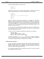
An .INI file defining ersatz names contains statements with the format:
ersatzname = filespec
filespec may be a complete or partial file specification. Here are some examples of
valid ersatz definitions:
HOME:
SYS:
ACCT:
CURNT:
PAYROL:
B:
=
=
=
=
=
=
16842753-DSK0:[1,2]
DSK0:[1,4]
DSK2:PAYABL.DAT[100,7]
16842757-DSK2:
ACCT:PAYMAS.DAT
DSK4:NOTE.TXT[12,1]
The ersatz name must start with a letter (not a number) and end with a colon. It may be
up to seven characters in length (including the colon).
You may use previously defined ersatz specifications within another ersatz definition
(we used ACCT: as part of the PAYROL: definition). You may not use an ersatz name
which you have not yet defined in an ersatz specification. In the example above, if the
PAYROL: definition came before the ACCT: definition, you would receive an ?Invalid
file specification error.
10.2How to Use Ersatz Names
When you specify an ersatz name as part of a command line, it is expanded according
to its definition in the INI file. The program using the ersatz name will use those
sections of the ersatz definition that apply.
For example, if you type: LOG PAYROL: RETURN (as it is defined above), the computer will
log you into the proper account—DSK2:(100,7). If you type VUE PAYROL: RETURN , it
would expand the command to VUE DSK2:PAYMAS.DAT[100,7]. As you can see,
using ersatz names can save you a lot of typing.
Another thing to note about ersatz names is you can "override" parts of the definition
when you use the ersatz name. For example, let us say you have another version of
PAYABL.DAT (as seen in the example above) in another account on the same disk, say
100,11. You could say:
LOG ACCT:[100,11] RETURN
and 100,11 would supersede the defined account of 100,7. Thus you would be logged
into DSK2: as before, but in account 100,11 instead. Only the account number changed.
Each ersatz definition as stored by AMOS has six parts: a CPU ID, drive name, drive
number, file name, file extension, and account number. When you override part of an
ersatz definition, as in this example, it replaces just that part of the definition you
override (in this case, the account number); the other parts of the definition are used in
the specification for the command. This is also what happens when you use a
System Operator’s Guide, Rev. 03
Defining Ersatz Names
Page 3
previously defined ersatz name in an ersatz definition, as with ACCT: and PAYROL:
above—to create the PAYROL: definition, AMOS takes the ACCT: definition and
replaces the file name and extension portions with PAYMAS.DAT.
If you define an ersatz name including a filename and extension, they will override any
default filenames/extensions.
Wildcard commands such as DIR and COPY will not allow you to override an
established default file extension if the ersatz definition has an extension but no
filename.
System Operator’s Guide, Rev. 03
SECTION 2 - CHAPTER 11
LANGUAGE DEFINITION FILES
The Language Support system gives you the ability to select which language you would like
your job to use. Because the languages are defined in Language Definition files (with a .LDF
extension), each job on the computer can independently use whatever language its user
wishes. This is useful in areas where more than one language is frequently used.
By "language" we mean which language the computer messages will be in, and which system
of symbols will be used. For example, if "French" is defined as the language for your job, you
see computer messages in French (provided the proper translation file was defined), and
French conventions are used for things like monetary symbols, punctuation, etc. It does not
necessarily mean you would be entering commands in French.
A file, SYSMSG.USA, contains all of the system messages in American English. AMOS uses
this file to convert its message codes into English messages. If this file is not loaded into
system memory by the system initialization command file, system messages will appear as
code numbers (see Section 6 - Appendix C for a list of the error codes and their meaning).
11.1Setting up the Language Definition Files
When generating a new system monitor using the MONGEN program, the computer will
prompt you for the name of the default language definition file after asking for the name
of the System Disk driver. The .LDF file you specify here will become the default
language for all jobs on the computer. If you only want one language to be used, this is
the only place you will have to worry about language files. Pressing RETURN here selects
the default language file ENGLSH.LDF[1,6], the table for American English.
If you want to have other languages available for use, you must also modify your system
initialization command file to include the definition files for those languages. You simply
use the SYSTEM command to load the desired .LDF files from [1,6] into system
memory at the time the system boots. For example:
SYSTEM SPANSH.LDF
SYSTEM GERMAN.LDF
System Operator’s Guide, Rev. 00
Page 2
Section 2 - Chapter 11
11.2Selecting a Language for your Job
A language is selected by use of the SET LANGUAGE command. When you type this
command, the system will display the current language for your job, and a list of
available languages. For example:
SET LANGUAGE RETURN
Current language is: ENGLISH (AMERICAN)
Languages available are:
DUTCH
GERMAN
FRENCH
SPANISH
To set a language, simply add the language name after the SET LANGUAGE command:
SET LANGUAGE SPANISH RETURN
If the language you specified is not available (no language definition file is loaded into
system memory), or you made a spelling error, you will see:
?Unable to locate requested language
And a list of the currently defined languages will be displayed.
The language definition support simply provides information on the
current language; it is up to the software to determine what action to take
based on that information. Not all software has been modified at this
time, so some of the system software will not support the language
capability.
For the assembly language programmer, a monitor call, GTLANG, has been defined.
This monitor call returns a pointer to the language definition table selected for the
current job. See your Monitor Calls Manual for more information. For the AlphaBASIC
programmer, an XCALL subroutine, GTLANG, returns the information in the language
definition table in a MAP structure. See your AlphaBASIC XCALL Subroutine User’s
Manual.
11.3Defining your own Language Definition Files
Alpha Micro provides a way for you to create your own language definition files based
on your own special needs. AMOS contains an .LDF file for American English (in
DSK0:[1,6]), and a special definition file, LDFSYM.M68 (in DSK0:[7,7]), which allows
you to define your own file. The macros used within the language definition files are all
contained in the file LDFSYM.M68. Each of these macros defines one of the language
definition file fields defined in the Monitor Calls Manual.
Each of these macros must be used in order, and all fields must be defined. For this
reason, the easiest way of creating a new language definition file is to simply copy and
modify one of the existing files. All arguments used by the macros are decimal.
System Operator’s Guide, Rev. 00
SECTION 2 - CHAPTER 12
PATCHING PROGRAMS
This chapter discusses the PATCH utility that allows you to install software patches into your
existing machine language program files. Alpha Micro continually uses and tests its software
long after that software is released to our customers. If an error should show up, or if a customer makes a request for an enhancement to the software, we try to distribute the improved
software as quickly as possible. In between scheduled software releases, this distribution
usually takes the form of "software patches."
A software patch is a change Alpha Micro provides for an existing program file in order to
incorporate an enhancement or a problem resolution to your version of the program. You will
receive a patch in one of two ways: as printed text or as a machine readable file (for example,
on a VCR cassette). If you receive the patch as printed text, you will need to create a text file
using AlphaVUE into which you will type the patch.
12.1The PATCH Process
PATCH is a DO file that applies a patch (in the form of a text file) to an existing machine
language program file. Patch files are a special type of assembler source file.
PATCH.DO assembles the patch file using M68 and then uses the PTCH.LIT program
to insert the changes into the existing program.
PATCH automatically checks to make sure the hash total and version of the existing
program file are correct, and then checks to see the hash total and version number that
would result from the patch are also correct. If the hash total or version number are
wrong, PATCH won’t patch your program file, leaving it unmodified. The format is:
PATCH [existing-program] WITH [patch-file]
where [existing-program] is the program you want to patch and [patch-file] is the text file
containing the patch to be made. The default existing program extension is .LIT. The
patch file must have an .M68 extension. For example, suppose you want to patch the
program TEST.LIT with the patch file TESTP.M68 (a text file containing the un-assembled patch). Enter:
PATCH TEST WITH TESTP RETURN
You will see a display as the patch occurs, giving information about the process. If an
error occurs, PATCH does not patch the existing program. For more information on
PATCH, see your System Commands Reference Manual.
System Operator’s Guide, Rev. 00
SECTION 2 - CHAPTER 13
THE DISK CACHE BUFFER MANAGER
A disk cache is an area of memory dedicated to the storage of frequently-used disk blocks. A
disk cache system can improve computer performance by reducing the amount of time used in
disk access. It is faster for the computer to access this cache in memory than it is to copy data
into memory from the disk device. The cache simply keeps as many of the most-recently
accessed blocks of files as it can hold—if you use a file frequently, the blocks of that file tend to
stay in the cache, and you can access it faster. You may also modify the cache to "lock in" the
blocks or files you wish it to contain.
The SET command allows you to turn disk cacheing on and off for logical disk devices. See
your System Commands Reference Manual.
The disk cache system works with blocks of data, moving them to and from the disk and
memory. Each block is 512 bytes of data. During this discussion, we talk about these blocks
when describing the I/O and cache processes.
You should remember what you are actually transferring may not look like it is in the form of
physical device "blocks." You may be doing data entry/data retrieval, in which case, it may look
like you are moving logical "records." Or you may be reading in or writing out "files." Both
records and files are viewed by the system as a block or as groups of blocks. For instance, if
you request a file be placed in the cache, the cache "locks in" all the blocks making up that file.
Alpha Micro products with an AM-515 or AM-520 or similar intelligent disk controller use
a different method of disk cacheing—see the appropriate chapter in Section 5 for more
information. If you have such a device, you only need to use the disk cache if you need
to lock specific files in memory.
13.1Theory of the Disk Cache
This section goes into detail on how the cache is organized. If you are not interested in
the technical background, you may wish to skip to the next section.
The disk cache system is divided into double-linked blocks. The cache is divided into
two queues, STATIC and DYNAMIC.
The STATIC queue contains those files you select to be "locked" into the cache—they
remain in the cache until you take them out. Each file residing in the locked queue has
a counter. When someone on the system locks a file, one is added to its counter (more
than one person can lock the same file this way). Only if the number becomes zero (all
persons that have locked that file unlock it) is the file removed from the STATIC queue.
System Operator’s Guide, Rev. 02
Page 2
Section 2 - Chapter 13
The DYNAMIC queue is the area containing the most recently accessed files. The
order is from most-recently used to last-used.
When the cache is searched for a particular block and that block is found in the
DYNAMIC queue, a copy is transferred out of the queue for use, and the block is moved
up to the front of the queue.
If a file is used frequently, its blocks most likely stay in the queue all the time. Blocks
not used frequently quickly pass through the DYNAMIC queue and be removed from the
queue as other blocks are added. If a block is removed from the STATIC queue, it gets
put at the end of the DYNAMIC queue.
The queue works something like a zip code—the numbers sectioning the area to be
searched so only a small group of blocks have to be compared, rather than searching
through every block in the cache.
13.2The Programs Making Up the Disk Cache System
There are two programs you should know of—DCACHE.SYS, which controls the cache,
and CACHE.LIT, the program allowing you to modify the cache.
DCACHE.SYS is initialized in the system initialization command file when the system
boots.
13.3Setting Up the Cache
The DCACHE.SYS program is used in the system initialization command file to set up
the cache. DO NOT modify your system .INI file directly—make a copy of it and
modify and test the copy! A SYSTEM command with the following form must be
added to the system initialization command file to initialize the cache:
SYSTEM DCACHE.SYS/N{/switch{/switch...}} SIZE
The switches are:
/R
/C
/L
/M
/U
Read only
Place only Random files within the cache
Place only Locked blocks in the cache
Dynamically lock/unlock the MFD
Dynamically lock/unlock the UFD
The SIZE parameter at the end of the line allocates the memory you want to give to the
cache. The more memory you have, the more blocks can be stored there. See below
for hints on how much memory you should allocate. The SIZE can be specified in
bytes, or with a K following it for Kilobytes, or an M for Megabytes. Here is an example
of a SYSTEM command to initialize the cache:
SYSTEM DCACHE.SYS/N/M/U 100K
System Operator’s Guide, Rev. 02
The Disk Cache Buffer Manager
Page 3
The /N switch above is not a DCACHE switch, but a SYSTEM switch causing DCACHE
to be initialized during system initialization.
13.4Displaying Information About the Cache
The CACHE command is used to modify and display the contents of the disk cache.
When used at AMOS command level from any account except [1,2], CACHE displays
the current contents of the cache. See the CACHE reference sheet in your System
Commands Reference Manual for more information.
13.5How to Make the Cache Most Efficient on Your System
There are three factors affecting the efficiency of the disk cache on your system:
How much memory you allocate to the cache
How many blocks you place in the locked queue
How many files you have on your system and how many are often in use
When you first begin using the disk cache, allocate it an amount of memory you think
will be effective and efficient for your system, and add those programs you know will be
used often to the locked area of the cache.
If you have limited memory on your system, you still may be able to use the disk cache
effectively. The disk cache programs themselves take up only about 2.2K of memory.
In order to have a functional Dynamic Queue, you need at least 20K of memory. If you
have less than 20K available, you will only be able to use the Static queue, but that can
contain some of your most-used files. You will not have full use of the disk cache
system, but you will still improve your system throughput.
The disk cache needs approximately 538 bytes of memory to store each block.
Therefore, if you allocated 50K to the disk cache, you would be able to store about 94
blocks.
Once you have allocated memory to the disk cache, run your system normally, and
check the cache a few times (using the CACHE command) and see what the efficiency
rating is. Try different memory allocations and/or add or subtract files from the locked
queue to find the best way to improve the cache’s efficiency.
In order to get a proper efficiency rating, your computer should be running one or more
of your common application programs. If you have a single-user computer, you will
have to get another job to run (or use the Task Manager system) to run such a program.
System Operator’s Guide, Rev. 02
Page 4
Section 2 - Chapter 13
You can also adjust the function and performance of the Disk Cache system by using
switches on the SYSTEM DCACHE.SYS command in the system initialization command
file. These switches affect how the cache works.
If you have a computer system where a lot of users are continually using a wide variety
of different files, the disk cache system may not save you much time. Indeed, it may be
the memory the cache is using is more valuable than the slight speed increase. If so,
perhaps you would be better off using the cache to lock UFDs and MFDs only.
If you have a computer where the same files are used often, and make up the bulk of
the work done on the computer, the disk cache system should give you noticeable
improvements in response time and throughput.
System Operator’s Guide, Rev. 02
SECTION 2 - CHAPTER 14
THE VIRTUAL DISK
The Virtual Disk (VDK) is a memory resident software disk. It is an area of memory defined like
a disk that is used to create temporary files so they can be retrieved faster than from the disk.
You can define specific files or types of files which should be created and maintained on the
virtual disk.
The VDK is simple to set up, and allows you to use wildcard specifications for the files you want
to control in memory. The VDK is very useful for speeding up programs that create temporary
files which are transported to other programs.
Because the Virtual Disk is a memory disk, any files residing there are lost when the
system loses power or is rebooted. VDK is usually used to store temporary files;if you
create a file on the virtual disk you want to save, you must use COPY to transfer it to a
physical disk.
You must set up the virtual disk as either a traditional or extended format disk; it can
only hold files intended for that type of disk. If you have a system with both traditional
and extended format disks on it, you will have to choose which type of disk you wish to
use with the virtual disk.
14.1How to Set Up the Virtual Disk
The first step is to edit a copy of your system initialization command file. DO NOT
modify the system initialization command file directly! Since the VDK is designed
to appear as a disk to AMOS, you define it as you would a disk device. Add the VDK0:
device to your DEVTBL statements. For example:
DEVTBL VDK
Add a BITMAP command:
BITMAP VDK,size,0
size is the size of the VDK memory—a decimal number defining the number of words of
the bitmap area. Each word is sixteen blocks. Therefore, the VDK memory area will be
a multiple of 8K. Next, add SYSTEM commands for the VDK programs (they must be
in the order shown):
System Operator’s Guide, Rev. 03
Page 2
Section 2 - Chapter 14
SYSTEM VDK.DVR[1,6]
SYSTEM VDKI.SYS/N
SYSTEM VDKCTL.SYS/N
Finally, add a command to MOUNT the VDK:
MOUNT VDK0:
You must mount the VDK after the above commands. Then finish out of your TEST.INI
file.
You cannot change the name of the virtual disk device. It must be VDK:
Next, create a file in DSK0:[1,4] called VDK.INI. This file contains wildcard specifications for the files you want to reside on the virtual disk. For example:
DSK5:*.TMP[]
ALL:*.TM?[]
DSK3:PAYROL.DAT[123,45]
DSK2:*.*[]
*.IPF
OVERFLOW = YES
The device and account specification defaults are DSK0: and [1,4].
You can’t use these wildcard specifications: ALL:*.*[], ALL:*.*, *.*[], or *.*.
The VDK.INI file is processed as a linked list. This means you can add to the file, then
run the VDKUTL program to make that entry effective without rebooting your system.
See the VDKUTL reference sheet in your System Commands Reference Manual.
The OVERFLOW command in the VDK.INI file controls how the system will react if the
VDK memory becomes full. If you specify OVERFLOW = YES, the system will try to
transfer the file that would not fit in virtual memory back to the default device. If
OVERFLOW = NO, you will just see a ?Device full error message. Explicit
commands to transfer files into virtual memory will not overflow.
14.2When Is the Virtual Disk Used?
The virtual disk software will only transfer a file into memory if it meets both of these
requirements:
1.The program or command specifying the file must be using the default device and
account specification; if it defines a specific device or account, such as
DSK1:[100,3], the virtual disk will not be used. In assembler terms, these fields in
the file’s DDB must hold the default value: D.CPU, D.DEV, D.DRV, and D.PPN.
System Operator’s Guide, Rev. 03
The Virtual Disk
Page 3
2.The file specification, taken with the current defaults, must match one of the
specfications in the VDK.INI file.
For example, assume DSK1:[100,4]*.TMP is included in VDK.INI. If you log to that
account and type:
VUE TEST.TMP RETURN
The file will be created in the virtual disk, since you are using the default device and
account specification for VUE, and it matches one listed in VDK.INI. If you save
changes to the file, they are stored on VDK:, not in DSK1:[100,4]. If you—or another
user—later call up this same file by specifying the disk or account (for example, VUE
DSK1:TEST.TMP), you will read the file from DSK1:, not VDK:, and so will not see any
changes stored on VDK:. Also, if the system is rebooted, any changes stored only on
VDK: will be lost. If you want to save your changes, always remember to copy them
from VDK: to the disk!
However, if you are logged into [100,0] and enter:
VUE TEST.TMP[100,4] RETURN
The file will not be put on the virtual disk, since you have specified an account rather
than using the default.
You can also specify that you want a file to be created on the virtual disk by using
VDK0: as the device name. For example:
OPEN #1000,"VDK:TEST.DAT",OUTPUT
This BASIC statement opens a file for output on the virtual disk, in the current default
account.
When you use this method to force a file to be created on the virtual disk, the account
where the file will reside must already exist on VDK0:. This is not true when a file is
placed on the virtual disk following the two rules given above.
System Operator’s Guide, Rev. 03
SECTION 2 - CHAPTER 15
FINDING INFORMATION IN
ALPHA MICRO DOCUMENTATION
This chapter discusses how to find information. Alpha Micro publishes a complete library of documentation covering the software and hardware products we sell. Some of our documentation
is shipped with your Alpha Micro computer, other books are shipped with specific software or
hardware products that can be added to your system. Of course, all Alpha Micro documentation can be ordered, either in individual documents or in library packages.
Because of the many products Alpha Micro sells, we have many different manuals, and you
may find it difficult sometimes to know which manual contains the information you need. This
chapter will try to guide you to the proper document, and hopefully give you a better understanding of how Alpha Micro organizes its documents and libraries.
15.1Where do I Start?
The first thing you need to ask yourself is—what is it I am looking for? Is it hardware or
software information? Does it have to do with a specific product, such as AlphaWRITE?
Once you know the general thing you are looking for, you can look at the categories
below and get suggestions on where to look. If you find you do not have the manual
you need, you can order manuals by contacting your Alpha Micro representative.
If you do have the manual in question, first look in either the Table of Contents or the
Index to find the topic you want information on. If you are still unable to find the
information, your Alpha Micro dealer or representative will be glad to help you.
15.2Where to Look
Here are some general categories of manuals, with suggestions of where to look first:
Hardware Manuals
Most Alpha Micro hardware devices have Product Description
and Installation manuals telling you about the product and
giving installation and use instructions.
AMOS System
Set-up
The System Operator’s Guide you are reading, and the
System Operator’s Guide to the System Initialization Command File give you information on all of the system functions
involved in system set-up, operation, and maintenance.
System Operator’s Guide, Rev. 00
Finding Information in Alpha Micro Documentation
AMOS System
Programs
Page 2
If you want to know what programs are available with AMOS,
or if you have questions about a command or program, the
System Commands Reference Manual contains a reference
sheet on each command or program that is part of the general
AMOS release.
The introductory chapters give you
background information about AMOS commands, and contain
lists of the commands by function, so if you know what you
want to do but don’t know what command does it, you can find
out.
If you cannot find information about a command in the System
Commands Reference Manual, it means that command or
program is part of a separately sold product. If you can’t
determine which product the command is for, ask your Alpha
Micro representative for help.
If you recognize what the command is related to, check the
document that describes that product. For example, if you
purchase AlphaWRITE, Alpha Micro’s word processor, the
software contains a program called AWCONV. AWCONV
allows you to convert a file to AlphaWRITE format. Although
AWCONV looks like a system command, it is documented in
the AlphaWRITE Reference Guide.
AMOS General
Information
When in doubt, look in your AMOS User’s Guide. This
document contains a lot of good, general information about
AMOS. What you need to know is likely to be discussed in the
User’s Guide, and it will point out where to go for further
information.
Programming
Langauges
Alpha Micro supports a number of programming languages,
each with its own manual.
Office Products
Alpha Micro offers a number of software packages designed
for use in the office environment. These products come with
complete documentation, and are rarely mentioned in the
standard AMOS documentation, which cannot assume the
presence of this type of software. Therefore, you will mainly
need to consult the documentation that came with the specific
software.
System Operator’s Guide, Rev. 00
SECTION 3
DISK MAINTENANCE
This section contains information about maintaining your hard disks.
System Operator’s Guide, Rev. 02
Section 3
SECTION 3
TABLE OF CONTENTS
CHAPTER ONE DISK ANALYSIS AND TROUBLESHOOTING DISKS
1.1 The SET DSKERR Command . . . . . . . . . . . . . . . . . . . . . . . . . . . . . . .
1.2 What is a Soft Error? . . . . . . . . . . . . . . . . . . . . . . . . . . . . . . . . . . . . . . .
1.3 What is a Hard Error? . . . . . . . . . . . . . . . . . . . . . . . . . . . . . . . . . . . . . .
1.4 The REDALL and RNDRED Programs . . . . . . . . . . . . . . . . . . . . . . . . .
1.5 The DSKANA Program . . . . . . . . . . . . . . . . . . . . . . . . . . . . . . . . . . . . .
1.6 How Do You Know if You Have a Problem? . . . . . . . . . . . . . . . . . . . . .
1.7 What to Do if You Find Disk Errors . . . . . . . . . . . . . . . . . . . . . . . . . . . .
1.8 What to Do if You Get a Soft Error . . . . . . . . . . . . . . . . . . . . . . . . . . . .
1.9 What to Do if You Get a Hard Error . . . . . . . . . . . . . . . . . . . . . . . . . . .
1.10 DSKANA File Errors . . . . . . . . . . . . . . . . . . . . . . . . . . . . . . . . . . . . . .
1.11 What Happens During Booting . . . . . . . . . . . . . . . . . . . . . . . . . . . . . .
1.12 How the Bootup Device is Selected . . . . . . . . . . . . . . . . . . . . . . . . . .
1.13 How to Reboot Your Computer . . . . . . . . . . . . . . . . . . . . . . . . . . . . . .
1
1
2
2
2
3
3
3
4
6
7
9
9
CHAPTER TWO LABELING AND IDENTIFYING DISKS
2.1 Contents of a Disk Label . . . . . . . . . . . . . . . . . . . . . . . . . . . . . . . . . . . .
2.2 Identifying a Disk (The HASHER Program) . . . . . . . . . . . . . . . . . . . . .
1
2
CHAPTER THREE HANDLING MEDIA FLAWS ON WINCHESTER DISKS
3.1
3.2
3.3
3.4
Media Defects on AM-520 Controlled Disks . . . . . . . . . . . . . . . . . . . . .
Media Defects on SCSI Disks . . . . . . . . . . . . . . . . . . . . . . . . . . . . . . . .
Media Defects on Non-self-configuring Disks . . . . . . . . . . . . . . . . . . . .
The BADBLK Program . . . . . . . . . . . . . . . . . . . . . . . . . . . . . . . . . . . . .
1
1
2
2
CHAPTER FOUR BACKING UP YOUR SYSTEM
4.1 Why Should You Back Up Data? . . . . . . . . . . . . . . . . . . . . . . . . . . . . .
4.2 Hints on Data Backup . . . . . . . . . . . . . . . . . . . . . . . . . . . . . . . . . . . . . .
4.3 Video Cassette Recorder Backup Hints . . . . . . . . . . . . . . . . . . . . . . . .
4.3.1 VCR Maintenance . . . . . . . . . . . . . . . . . . . . . . . . . . . . . . . . . . . . .
4.3.2 Recording Speed . . . . . . . . . . . . . . . . . . . . . . . . . . . . . . . . . . . . .
4.3.3 The Cassettes . . . . . . . . . . . . . . . . . . . . . . . . . . . . . . . . . . . . . . . .
4.3.4 Verifying Cassettes . . . . . . . . . . . . . . . . . . . . . . . . . . . . . . . . . . . .
4.3.5 Calibrating Your VCR . . . . . . . . . . . . . . . . . . . . . . . . . . . . . . . . . .
System Operator’s Guide, Rev. 02
1
1
2
2
2
2
3
3
Page 2
Section 3
CHAPTER FIVE WARM BOOTING AND RESTORING A DISK
5.1 Creating the Warm Boot Monitor File (WRMGEN) . . . . . . . . . . . . . . . .
5.2 Testing the Warm Boot Monitor . . . . . . . . . . . . . . . . . . . . . . . . . . . . . .
5.3 Backing Up the Warm Boot Monitor . . . . . . . . . . . . . . . . . . . . . . . . . . .
5.4 Hints on Building and Using Warm Boot Monitors . . . . . . . . . . . . . . . .
5.4.1 Re-initializing the Disks . . . . . . . . . . . . . . . . . . . . . . . . . . . . . . . . .
5.4.2 Recovering Individual Files . . . . . . . . . . . . . . . . . . . . . . . . . . . . . .
5.4.3 Miscellaneous Situations . . . . . . . . . . . . . . . . . . . . . . . . . . . . . . .
1
2
2
3
4
6
7
CHAPTER SIX CONSOLIDATING DISK FILES
6.1
6.2
6.3
6.4
Reasons for Packing a Disk . . . . . . . . . . . . . . . . . . . . . . . . . . . . . . . . .
Displaying the Number of Free Blocks . . . . . . . . . . . . . . . . . . . . . . . . .
Displaying the Bitmap . . . . . . . . . . . . . . . . . . . . . . . . . . . . . . . . . . . . . .
The DSKPAK Program . . . . . . . . . . . . . . . . . . . . . . . . . . . . . . . . . . . . .
1
2
2
2
System Operator’s Guide, Rev. 02
SECTION 3 - CHAPTER 1
DISK ANALYSIS
AND TROUBLESHOOTING DISKS
There are a number of diagnostic tests you can run to check your disk media, the disk controller
and the physical device itself. This document discusses these disk analysis programs.
1.1The SET DSKERR Command
Before running any of the tests we discuss below, it is a good idea to use the SET
DSKERR command. If you do not use SET DSKERR, the computer does not report the
location of a hard error. Once you have SET DSKERR, the computer not only reports
any hard errors, but also tells you at what disk location the error occurred.
The computer makes an exception for floppy disks and certain other
disks (such as the AM-520)—SET DSKERR tells the computer to report
soft errors as well.
SET DSKERR affects error reporting only for the job that used the SET command.
1.2What is a Soft Error?
A soft error is a read-error. When a soft error occurs, the computer has to retry reading
the data in a specific disk location. The computer does not report soft errors unless you
use SET DSKERR. When a set number of soft errors have occurred at the same disk
location (usually eight), the computer reports a hard error.
An occasional soft error is not in itself an indication of serious problems, but frequent
soft errors may indicate maladjustments in the physical device or disk controller, or
problems with the disk media itself. The particular message the computer uses to report
a soft error depends upon the type of device; see your AMOS User’s Guide for a list of
soft error messages. For example, if the computer had to retry reading a disk block on
a floppy disk drive four times, you might see something like this:
CRC Error - DDA1: Block 145
System Operator’s Guide, Rev. 00
Page 2
Section 3 - Chapter 1
1.3What is a Hard Error?
A hard error occurs when the computer has repeatedly tried to read the same disk
location, but has failed to do so. A hard error is serious—it indicates the computer
cannot read a block on the disk.
If any of the disk diagnostic tests is not able to complete an analysis because of a hard
error, it tells you so:
?Cannot read [filename] - device error
If you have DSKERR set, AMOS displays the disk location of the hard error.
example:
For
AM420 ERROR CODE 4 FOR DRIVE 1 BLOCK 12
(CYLINDER 0 HEAD 0 SECTOR 12)
To see what the error codes for a specific disk drive mean, see the hardware documentation that came with that drive.
1.4The REDALL and RNDRED Programs
Both REDALL and RNDRED do read tests on a specified hard or floppy disk. REDALL
reads all disk blocks (or the number you specify) beginning with the first block on the
disk. RNDRED does random read tests. Neither REDALL nor RNDRED change the
data on your disk; they merely read the data and report any read errors that occur.
See the reference sheets for REDALL and RNDRED in your System Commands
Reference Manual for information on using them.
1.5The DSKANA Program
Use of the DSKANA program is a very important part of your disk maintenance routine.
DSKANA analyzes the data on a specified disk, and usually rewrites the bitmap.
DSKANA also reports lost and mis-linked disk blocks, inconsistent block counts, and
other file errors. Use DSKANA frequently on every disk on the computer. You should
make it a practice to use DSKANA on every disk just before you back it up or pack the
files on the disk.
NEVER use DSKANA while other users are accessing the specified disk
(unless you are using the /C option); to do so may damage the bitmap
and the files on the disk. Make sure the disk you are analyzing is
write-enabled if DSKANA is going to rewrite the bitmap out to the disk.
Before you use DSKANA, you must log into account [1,2].
One reason to run DSKANA frequently is it reclaims temporarily allocated blocks so they
can be used by files.
System Operator’s Guide, Rev. 00
Disk Analysis and Troubleshooting Disks
Page 3
You may want to have DSKANA examine a disk without re-writing the bitmap. Here is a
sample scenario illustrating why the /C option is sometimes a wise choice:
Say you have an automatic backup procedure that runs at night, and that procedure
performs a DSKANA to check for disk errors. If a user forgets to exit a text editor
program before leaving at night (thus leaving a file open), when the automatic backup
procedure runs DSKANA on that disk (and if the /C option is NOT used), the incomplete
bitmap (incomplete because it does not take the open file into account) gets written out
to the disk. Then, when the user exits the text editor the next morning (closing the file
the computer no longer remembers is open), a disk bitmap error occurs, corrupting the
data on the disk.
1.6How Do You Know if You Have a Problem?
If any of the disk analysis programs show you an error message indicating either hard or
soft disk errors, it could mean you have a problem with your disk or the software, or with
your data. See Section 6 - Appendix C to determine exactly what the problem is.
1.7What to Do if You Find Disk Errors
Disk errors can come to your attention in one of two ways:
A program on the computer (for example, one of the disk diagnostic
programs) reports a soft or hard error.
The DSKANA program reports file errors (indicating the blocks on the disk
are incorrectly linked).
In either case, you must immediately do what you can to restore the integrity of the data
on the disk. Remember: the procedures below are aimed at effecting a partial recovery
of your data. Once the linking structure of your disk or the disk media itself goes wrong,
retrieving the data on that disk is difficult. The most effective measure is a preventive
one: run DSKANA regularly, so if trouble does occur, you catch it before it has done
major damage to your data. Make frequent backups so you can easily restore damaged
data.
1.8What to Do if You Get a Soft Error
If your computer has trouble reading a disk location (a soft error), it retries that read
operation a number of times before it gives up and declares that disk block to be
unreadable. On some disks, if you do not have the SET DSKERR option in effect, the
computer does not report these retries; instead, after a set number of soft errors occur,
the computer reports a hard error. On some hard disks, the computer does not report
soft errors at all, but it will at least tell you where on the disk the hard error occurred.
System Operator’s Guide, Rev. 00
Page 4
Section 3 - Chapter 1
If you begin to see soft errors when reading a particular disk, it is a good idea to perform
these disk cleanup procedures before the soft errors can develop into hard errors.
If the errors occurred on a floppy disk, and if you have made no changes to the files on
the disk since your last backup was made, all you have to do at this point is clear the
disk by formatting it and initializing it. Then use the REDALL program to read the
freshly initialized disk to make sure the disk is okay. If the disk media seems to be
healthy, you can copy your backup onto the empty disk.
If the errors occurred on a Winchester disk, you may wish to follow the diagnostic steps
described below before you resort to initializing the disk and restoring your files from a
backup. Winchester disks can hold a large quantity of data, and certifying and
initializing are not recommended except in extreme emergencies.
If you have changed some files since your last backup, you must attempt to save the
data on the damaged disk. If the computer can still read the disk blocks (that is, if you
have soft rather than hard errors), use the REDALL program to make sure the output
disk is good, then use the COPY command to copy all files over to a good disk.
1.9What to Do if You Get a Hard Error
If you see a hard error, it means the computer is not able to read at least one of the disk
blocks. Use the SET DSKERR command. Then run REDALL to try to read the disk.
REDALL tells you which disk blocks are unreadable. Write those bad block numbers
down.
Now there are a couple of things you can try. You may be able to fix the hard error by
simply re-computing the block CRC (Cyclic Redundancy Check). Use the FIXCRC
program to do so:
Enter FIXCRC and the specification of the questionable logical device. Then type the
number of the disk block you want to check and press RETURN . For example, to check
block #20 on DSK1:, log into account [1,2] and enter:
FIXCRC DSK1:20 RETURN
FIXCRC reads the block into memory and writes it back to the disk. If the block cannot
be corrected, FIXCRC displays an error message.
Do this for all bad disk blocks on the disk.
This procedure does not ensure your data is intact (fixing the CRC error
may actually cause some data in the block to be lost; however, correcting
the CRC does allow the computer to read the block.) You may want to
dump the restored block with the DUMP BLOCK command to see if you
need to modify the data in it.
System Operator’s Guide, Rev. 00
Disk Analysis and Troubleshooting Disks
Page 5
If using FIXCRC does not fix the hard errors on the disk, you must take more stringent
measures to get rid of the bad blocks. To find out what files the bad blocks belong to,
use DSKANA with the /L or /E options. DSKANA exits when it finds the first bad block,
but tells you where the bad block is located. For example, if there is a block marked as
bad in the file VARSET.BAS, the DSKANA display for that file might look like this:
VARSET BAS
5
6
7
10
12
AM520 ERROR CODE 4
FOR DRIVE 1 BLOCK 9 (CYLINDER 0 HEAD 0 SECTOR 9)
Keep track of the files in which the bad blocks appear.
command to check an individual file for a hard error.
You can use the DSKFIL
Using DSKCPY to copy the damaged disk to another disk won’t solve the
problem—DSKCPY exits and returns you to AMOS command level when it encounters
a hard error.
Simply erasing the bad files will not help either. If you erase a file containing a bad
block and then run DSKANA again, DSKANA frees up the bad block so the computer
can allocate it to another file.
The only solution is to erase the bad files and then to use the COPY command to copy
the good files over to another disk. The procedure is:
1.Make sure the disk you are copying to has no hard errors—use the REDALL
program or the DSKANA program to check it.
2.Erase the bad files by using the ERASE command. Do not run DSKANA again on
the bad disk at this point, or the bad blocks will be freed again.
3.Log into the System Operator’s account and copy the good files on the disk over
to the backup disk:
LOG [1,2] RETURN
COPY DDA2:=DDA1:[] RETURN
The COPY command above copies all accounts on DDA1: over to DDA2:. If two
files exist on DDA1: and DDA2: with the same name, extension, and account
number, the command above deletes the file on DDA2: and replaces it with a copy
of the corresponding DDA1: file. If you don’t want COPY to replace duplicate files,
use the /NODELETE switch. For example:
COPY DDA2:=DDA1:[]/NODELETE RETURN
Because you are logged into the System Operator’s account, the command above
copies all files in all accounts on DDA1: over to the corresponding accounts on
DDA2:. If the corresponding account does not exist on DDA2:, the COPY
command creates it, transferring to it any password associated with the source
account.
System Operator’s Guide, Rev. 00
Page 6
Section 3 - Chapter 1
4.Restore the files you erased. Copy them over to the good disk from your most
recent backup disk.
5.Back up the good disk.
6.Now that you have copied all of the good files over to the new disk, get rid of the
bad blocks on the original disk.
If the original disk is a Winchester, see Section 3 - Chapter 3,
"Handling Media Flaws on Winchester Disks" for information on
correcting the disk.
If hard and soft errors are frequent occurrences on your computer, you ought to
take a look at the disks themselves. For example, if you are using floppy disks,
are you storing them correctly? Are they scratched or dusty? You might also
check your disk controller board and the physical device itself for maladjustments.
1.10DSKANA File Errors
For the purposes of this discussion, we assume you have already handled any soft or
hard errors on the disk, and the only problem with the disk at this point is in the linking of
the disk blocks.
If DSKANA reports file errors or lists disk blocks under the message:
[The following blocks were in a file but not marked in use]
the block linking structure of the disk is in error. You must take immediate steps to
recover the data on your disk. The procedure is:
1.If you did not use the /L or /E switch, run DSKANA again using one of these
switches.
2.Look for the file error messages in the display (see the DSKANA reference sheet
in your System Commands Reference Manual). Their location in the display
indicates which disk blocks are incorrectly linked, and this tells you which files are
bad. For example, if part of the DSKANA display looks something like:
DSKANA DSK3:/E RETURN
[Begin analysis of DSK3]
[20,1]
Block 7 - Block used in previous file in DSK3:LOG.LST[3,4]
[30,5]
then you know a disk block used by the file LOG.LST was also used by another
file. Two files cannot share the same disk block.
System Operator’s Guide, Rev. 00
Disk Analysis and Troubleshooting Disks
Page 7
3.If you are fortunate enough to have a very recent backup disk, and the files you
have changed since that backup are okay, you can simply copy those changed
files from the damaged disk over to the backup disk, which now becomes your
original. Of course, this assumes the backup disk is all right. You might make it a
practice always to run DSKANA before backing up a disk, so you know your
backup disk is always good. Now initialize the damaged disk; this clears it.
4.If you are not so lucky as to have a recent backup disk, you must do what you can
to salvage the data on your original disk:
a.Make a disk backup so you have a copy with which to work.
b.Now that you have found out what files are bad, use the ERASE command
to erase those files from the disk. If you do not do so, the errors in the
linking structure will propagate, and you will lose even more data.
c.After clearing the bad files from the disk, run DSKANA again to make sure
all problems have been cleaned up.
d.Once no more file errors show up, you must set about restoring the files you
have erased. If you have old backup disks containing good copies of the
files you have just erased, restore those files on your disk by copying them
over from the backup disks.
e.Make a final backup copy of your newly restored disk.
The discussion above assumes damage has been done only to your files; if the linking
structure of the disk directories themselves is bad, you may have to copy off of the disk
whatever files you are able to, and then initialize the disk and start over with a new
account structure.
A systems expert may be able to reconstruct disk directories by using DSKDDT to
actually change the binary data on the disk. Directory entries are not stored in straight
ASCII, but in a special packed format called RAD50; you will have to make the
conversion yourself. Using DSKDDT to reconstruct directories is very dangerous; do
not try it except as a last resort, and be sure to make a backup first!
1.11What Happens During Booting
This section discusses "Booting" your system—what happens when you power up your
computer or push the reset button.
Once you understand the specific steps your computer goes through when booting up,
you will be better able to diagnose problems on that rare occasion when a computer
fails to boot.
The front panel status display can help you in determining why a bootup
failed, since it displays specific status codes at various points within the
System Operator’s Guide, Rev. 00
Page 8
Section 3 - Chapter 1
bootup procedure.
these status codes.
See your system owner’s manual for information on
When you power up or reset your computer, a specific sequence of events occur; if any
one of these steps fails, your computer will not boot up.
When you press the reset button, the CPU starts executing instructions at the address
set up in its internal logic. The address is the address of a PROM (Programmed
Read-Only Memory) on the CPU board itself. The program in the PROM transfers itself
into memory on your computer at location F000 through FFFF (hex), 170000-177777
(octal). If your memory in these locations is bad, the computer start-up will not proceed
beyond this step. The PROM program (called the "bootstrap loader") is now in RAM
(Random Access Memory) and it begins to execute.
If you have a Winchester system containing a Video Cassette Interface
set up to warm boot from the VCR, the PROM will initiate a warm boot
instead of following the steps below. See Section 3 - Chapter 5 for
information on warm booting. If your system does try to warm boot from
the VCR, there must be a tape playing in the VCR.
The bootstrap loader loads a copy of the operating system skeleton monitor (the system
monitor file in account [1,4] of your System Disk) into memory beginning at location zero
and extending as far as necessary.
When the system monitor file is in memory, it executes the initialization routine (INITIA)
residing within itself. The purpose of INITIA is to scan memory to determine how much
is available, and then to set up a user memory partition in the last 96K of memory (or
1/4 of available memory, whichever is smaller). This user partition is temporary, and is
just used to execute the system start-up functions under the control of the system
initialization command file.
During system start-up, certain programs cause the monitor to create new data areas at
the end of itself; these areas include terminal definition tables, job control blocks, device
tables, bitmap areas, etc. Your system initialization command file may also optionally
specify a list of programs to be added to the resident monitor area of memory (called
"system memory").
You can see the size of the monitor is not fixed, but expands during system start-up.
This is why INITIA allocates a temporary user memory partition in the last 96K of
memory, so the monitor has room to grow from memory location zero without
overlapping the area in memory where the system initialization command file is being
processed. This is also why the last command in the system initialization command file
must be MEMORY 0; this command de-allocates the temporary user partition under
which the computer boots, and gives the Operator Job the rest of available memory not
already assigned to other jobs.
Once INITIA is through setting up the user partition, the monitor reads in the system
initialization command file. Each line in the file represents one system function or parameter which determines the characteristics of the running monitor. As the monitor reads
in a line, it loads the specified command program from DSK0:[1,4] and executes it.
System Operator’s Guide, Rev. 00
Disk Analysis and Troubleshooting Disks
Page 9
The first thing the system initialization command file does is define one or more jobs;
next, it defines one or more terminals. The monitor automatically attaches the first job
defined (called the "Operator Job") and the first terminal defined (called the "Operator
Terminal") and then proceeds to process the rest of the system initialization command
file under the control of that job in the temporary memory partition allocated by INITIA.
The monitor executes each command line as it would a command in any other command file. However, because this command file is the system initialization command
file, the monitor performs some of the commands differently than it would the same
commands after the computer is up and running. The execution of certain commands
(for example, JOBS, TRMDEF, DEVTBL, etc.) performs the actual system generation.
After the last line of the file has been processed, the computer is up and running.
A question may occur to you—if the system initialization command file contains the
definitions for all of the devices, how is the monitor able to access DSK0: to look for the
system initialization command file and other files in DSK0:[1,4]?
The driver for the System Device is embedded within the monitor. This was done when
the monitor was generated by the MONGEN program. And, the monitor knows the
system initialization command file is in account DSK0:[1,4]. However, until it processes
the system initialization command file, DSK0: is the only device the monitor knows
about.
1.12How the Bootup Device is Selected
This section discusses how the system chooses which device to read the system
monitor file and System Initialization Command File files off of when booting.
Normally, your computer boots off of the fixed disk. With some computers, you can
select an alternate boot device, such as a floppy disk or a Video Cassette Recorder
(using a warm boot tape).
The particular pattern your computer follows in looking for the bootup device depends
on the Boot ID jumpers or switches set on your computer. See your Owner’s Manual for
the boot settings for your computer.
1.13How to Reboot Your Computer
The easiest method to boot the computer is, of course, just to power it up or to push the
RESET button of a computer that is already on. Make sure before rebooting that all
users are aware you are about to reboot, so they have a chance to close all files and
halt any tasks they are running.
Once the system is reset, it will "forget" everything it was doing before.
That means, for example, if you were editing a file using AlphaVUE, and
you did not get a chance to SAVE or FINISH out of the file, anything you
entered since the last SAVE will be lost.
System Operator’s Guide, Rev. 00
Page 10
Section 3 - Chapter 1
You always need to use the RESET button if the system has "hung" and will not
respond to commands from any user’s terminal.
If for some reason you want to boot with a particular monitor that is NOT your usual
system monitor file, or if you want to boot with a system initialization command file other
than your normal one, you will use the MONTST command.
For information on using MONTST, see the MONTST reference sheet in your System
Commands Reference Manual.
System Operator’s Guide, Rev. 00
SECTION 3 - CHAPTER 2
LABELING AND IDENTIFYING DISKS
The LABEL program gives you a way to label a disk with descriptive information and to display
that information. Disk labels are stored in Block 0 of the disk, and are used to allow both you
and your programs to verify the correct disk has been mounted. As the System Operator, you
may want to use the LABEL program on the disks on your system.
AMOS 2.0 and later system require all disks have a label. If you do not create a
label, SYSACT will create a blank label.
Labels are also important for removable backup media, such as VCR or magnetic tapes, floppy
diskettes, etc.
2.1Contents of a Disk Label
Systems programmers may be interested in the exact format of the disk label. Note not
all of the defined fields are presently used by the disk identification software; these
unused fields will be used by future releases of Alpha Micro software.
Field
Size
Contents
Header
Volume Name
Volume ID
Creator
Installation
System Name
Creation Date
Access Date
Backup Date #1
Backup Vol. ID #1
Backup Date #2
Backup Vol ID #2
2 words
40 bytes
10 bytes
30 bytes
30 bytes
30 bytes
4 bytes
4 bytes
4 bytes
10 bytes
4 bytes
10 bytes
125252 : 052525
ASCII text
ASCII text
ASCII text
ASCII text
ASCII text
System date format
System date format
System date format
ASCII text
System date format
ASCII text
The fields are:
Header
Used to show the disk is labeled. If the flag words are not
correct, certain programs will ignore the label.
Volume Name
An ASCII string describing the disk. This field is designed to
be a description of the contents of the disk.
Volume ID
A short ASCII string describing the disk. This field is used by
programs checking for the proper disk being mounted.
System Operator’s Guide, Rev. 00
Page 2
Section 3 - Chapter 2
Creator
An ASCII string describing who created this disk.
Installation
An ASCII string naming the site where the disk was created.
System Name
An ASCII string giving the name of the particular computer
system, within an installation, on which the disk was made.
Creation Date
The original date on which the disk was labeled.
Access Date
The date the disk was last MOUNTed.
Backup Date #1
The date of the last backup (the "parent" backup). This field
gives the date of the most recent backup. This field is
reserved for future use.
Backup Volume ID
#1
The volume ID field of the disk on which the most recent
backup (the "parent" backup) exists. This field is reserved for
future use.
Backup Date #2
The date of the "backup before last" or "grandparent" backup.
This field is reserved for future use.
Backup Volume ID
#2
The volume ID field of the disk on which the ID "grandparent"
backup exists. This field is reserved for future use.
2.2Identifying a Disk (The HASHER Program)
While the disk label helps you to identify the disk, another method of determining the
contents of the disk is to create a hash total for that disk. A hash total is a number that
uniquely identifies data. The HASHER program allows you to generate a hash total for
a specific disk. The hash totals for two disks will only be the same if the contents of
those disks are identical.
You may find HASHER helpful if you are making multiple copies of a disk using
DSKCPY. If the hash total of the master disk does not match the hash totals of the
disks copied to, the copies are not perfect. To use, enter:
HASHER RETURN
When the system asks for the input drive, enter the name of the disk for which you want
hash totals:
Input drive: DSK2: RETURN
HASHER displays the number of blocks it is working on, and then the Hash number.
System Operator’s Guide, Rev. 00
SECTION 3 - CHAPTER 3
MEDIA FLAWS
ON WINCHESTER DISKS
An inherent characteristic of Winchester disks is the technology giving them such a high density
of data also makes a small number of media flaws a common occurrence. The operating
system or the disk keeps a record of the places on the disk where the media is bad—these
places are thus not used when storing data. Various disks handle these bad blocks in various
ways. This chapter discusses how disks handle bad blocks, and how you can handle bad block
problems.
3.1Media Defects on AM-520 Controlled Disks
Disks controlled by the AM-520 controller contain an internal list of the bad blocks on
the disk. This list cannot be accessed, but you can modify it using the BADBLK
program. If you discover a bad block on your disk, you can add that block number to
the internal error list with BADBLK. The disk will then "skip" over that bad block when
writing to the disk. If you add a large number of bad blocks to the list, you may notice
system performance problems caused by the disk doing alot of comparing. The
CRT520 program can be used to re-certify your disk, which will "incorporate" your
changes into the internal list. This makes it easier for the computer to by-pass the bad
blocks. See your System Commands Reference Manual and/or the documentation that
came with your AM-520 software for more information.
AM-520 controlled disks contain a BADBLK.SYS file (like non-self-configuring disks—see below), but do not use the file.
3.2Media Defects on SCSI Disks
SCSI controlled disks have an internal list of bad blocks. On AM-515 controlled disks,
you must use the FMTSCZ program to format the drive in order to add new bad blocks.
On controllers that use a SCSI interface, you may use the BADBLK program to add bad
blocks to the internal list. See your System Commands Reference Manual for
information.
System Operator’s Guide, Rev. 02
Page 2
Section 3 - Chapter 3
3.3Media Defects on Non-self-configuring Disks
Non-self-configuring disks keep track of bad blocks in a disk file called BADBLK.SYS in
DSK0:[1,2]. This file is created when the disks are certified at Alpha Micro prior to
delivery.
After the disks are installed at your location, AMOS consults this
BADBLK.SYS file to see what tracks to avoid whenever you access the disk. It is very
important that this file is not destroyed—AMOS commands such as COPY and
RENAME will not affect this file.
3.4The BADBLK Program
The BADBLK program allows you to see the contents of the BADBLK.SYS file.
BADBLK also verifies the BADBLK.SYS hash total. The BADBLK.SYS file is used by
the monitor in this way:
The DEVTBL command automatically reserves space for an Alternate
Track Table in system memory.
The MOUNT command reads the BADBLK.SYS file into the Alternate
Track Table whenever a disk is mounted.
Whenever a disk access is requested, the disk driver scans the Alternate
Track Table to see if the requested block is in a track which is marked as
bad. If so, a translation is performed to access the requested block within
the alternate track assigned to that bad track. The actual allocation of
alternate tracks is device dependent.
When the system is being booted, the bootstrap routine reads in
BADBLK.SYS to handle the case where the system monitor program (for
example, AMOS32.MON) is allocated on an alternate track.
See the BADBLK reference sheet in your System Commands Reference Manual for
information on using BADBLK.
System Operator’s Guide, Rev. 02
SECTION 3 - CHAPTER 4
BACKING UP YOUR DATA
Backing up the data on your disks is probably the most important job of the System Operator.
You should make regular backups as part of your daily or weekly routine. How often you back
up your system will depend on how often the data on your system changes significantly—for
some systems, this will be every day, for others it might be once a month.
Alpha Micro offers a number of different media on which you can back up your system—floppy
disks, VCR tapes, magnetic tape, etc. By using the Task Manager, you can even automate
your backup procedure.
No matter what type of backup media you have on your system, there is a single set of
commands you use to back up and restore file on your system. See the BACKUP, RESTOR,
and BAKDIR command reference sheets in your System Commands Reference Manual for
information about what can be done, and how.
In this chapter, we are going to discuss the theory of backing up your system, and give you
some information on how to make the backup procedure easier and more efficient.
4.1Why Should You Back Up Data?
Your data is very important to you. No matter how good your computer hardware is, or
how well you install and use your software, sometimes things go wrong. Your disk
could become corrupted, someone on your system could enter the wrong command and
delete important files, a fire could damage your computer, etc. Backing up your data is
a safeguard against data loss.
4.2Hints On Data Backup
Alpha Micro provides many ways to back up data—on floppy disks, VCR tapes,
magnetic tape, etc. No matter what kind of media you have chosen to back up your
data with, there are a few things you should keep in mind:
Back up often! How often you back up your data will depend on how often you
enter new data, or update old data, on your system. It is a good idea, however, to
back up your system after every important update of data. For some systems, this
may mean every evening, for others, once a week, etc.
You can usually make your backup operation much easier by automating it.
AMOS has powerful command files that make repetitive tasks easy. And there is
the Task Manager, Alpha Micro’s background batch processor, that can run a job
System Operator’s Guide, Rev. 00
Page 2
Section 3 - Chapter 4
without user supervision. Using the Task Manager, you can set up the backup
task to run after business hours. See your Task Manager User’s Guide for
information.
It is a good idea to use the "Parent—Grandparent" system of backing up. In this
system, you use two (or more) backup media in sequence, so you always have
multiple media with backed-up data on them—the most recent (Parent) and older
(Grandparent). This protects you in case something goes wrong during the
backup process—you will never be recording over your only backup media.
You may want to periodically make a backup copy of your system and put that
media in a permanent storage area away from your office or building, to protect
your data against fires or other disasters.
4.3Video Cassette Recorder Backup Hints
One of the easiest and most popular backup systems for Alpha Micro computers is the
VCR backup. The paragraphs below give you some helpful hints.
4.3.1VCR Maintenance
It is very important to keep the read/write heads of the VCR clean. As the heads
become dirty, the number of data errors you see will increase. In fact, if you begin to
see more data errors as time goes by, the first thing you can suspect is your VCR heads
need cleaning.
For information on performing preventive maintenance on your VCR and on cleaning
the heads, see the owner’s manual that came with your VCR.
4.3.2Recording Speed
Most VCRs allow three tape speed settings: standard play, long play, and extended long
play. For maximum data reliability, use standard or long play mode. Or, if you do use
extended long play, specify extra copies to the VCRSAV command to increase data
reliability.
4.3.3The Cassettes
You can use either 60/120 minute, 120/240 minute or 90/180 minute (Beta) cassettes
with your Alpha Micro system, but there are a few limitations. Video cassettes were not
originally intended to record data, and as a result exhibit a higher error count than other
types of magnetic tape. To create a backup medium as reliable as other methods,
blocks of data are repeated when they are recorded on a cassette.
System Operator’s Guide, Rev. 00
Backing Up Your Data
Page 3
This repetition affects the amount of data that can be stored on a single cassette. As
the VCR unit records data, it automatically stores multiple copies of the data on the
cassette, and you can specify more extra copies if you wish.
To protect data already written on a cassette, break off the plastic tab on the back of the
cassette. This prevents the recorder from recording on the cassette. When you decide
you no longer wish to save the data, you can place a piece of gummed tape over the tab
opening and record as usual.
It is difficult to predict exactly how much data you can store on one video cassette. The
capacity depends on the length of the tape, the recording speed, the number of copies,
and the type and number of files being transferred. Also, the length of time it takes to
back up a group of files can be from a few minutes to several hours for the same
reasons. You will have to experiment with your own system to determine the amount of
data you will want to save on a single cassette.
4.3.4Verifying Cassettes
Although the VCR software contains internal controls to make sure the data written on a
cassette was copied correctly, after a great many saves on the same cassette, you will
find the cassette media may begin to wear out, resulting in soft errors, much the same
as standard magnetic tape will wear out.
Some number of soft errors on a cassette is perfectly normal, and does not indicate any
data was lost, but if the ratio of total blocks read to soft errors is less than 100 to one,
you should suspect your cassette is beginning to wear out, the read/write heads on your
VCR need cleaning, or some other potential problem is beginning to occur with your
equipment.
To keep track of the condition of your media, we recommend you use the CRT610 command with the /CHECK option after every data backup to check the cassette.
CRT610/C will give you the reliability ratio of the cassette. You may want to write this
ratio on the cassette case itself, so you can be aware of any deterioration that occurs.
Although new cassettes can be used without any preliminary preformatting, it is a good
idea to use CRT610 to verify new cassettes before you use them (at least one cassette
per batch) so you are sure the cassettes are of good quality. See your System
Commands Reference Manual for more on CRT610.
4.3.5Calibrating Your VCR
If you have a VIDEOTRAX remote-controlled VCR, you may use the /CALIBRATE
option of the CRT610 command to make the interaction between the backup software
and your VCR more efficient. The calibration only needs to be done once for each
VCR. See your System Commands Reference Manual for information on using
CRT610 and /CALIBRATE.
System Operator’s Guide, Rev. 00
SECTION 3 - CHAPTER 5
WARM BOOTING
AND RESTORING A DISK
A warm boot monitor is an abbreviated version of your system monitor containing just enough
information to get your computer up and running in one memory partition and with one terminal
when your System Disk has been accidently erased or written over. It was designed
specifically for the use of computers that contain only Winchester disks—such computers must
be able to boot from something other than a disk in case something happens to one of the
Winchester disks. If you have only Winchester disks on your computer, a warm boot tape
is a necessity.
After you have done a warm boot, you can restore other files to your computer from backup
tapes, and do a normal boot to restore your entire computer to its former configuration.
This chapter dicusses how to create, test, and save the warm boot monitor. We also talk about
how to determine what files to load into the warm boot monitor you create, and how to use the
warm boot monitor to perform an actual disk recovery.
5.1Creating the Warm Boot Monitor File (WRMGEN)
You will use the WRMGEN program to create the warm boot system monitor file on the
disk. Then you will use BACKUP, or another appropriate program, to copy this monitor
file onto a backup media.
Before you run WRMGEN, you should run the DEVTBL and BITMAP programs. Make a
note of the devices on your computer, and whether they are sharable or not, and the
BITMAP size for your computer. When you have this information, run WRMGEN. See
your System Commands Reference Manual for instructions.
5.2Testing the Warm Boot Monitor
Now you have a warm boot monitor file on the disk. Before you transfer it to the backup
media, test it to make sure it works as you would like it to. You do not want to wait for
an emergency to see if your warm boot tape works! The program you use to test a
warm boot monitor is called MONTST.
System Operator’s Guide, Rev. 00
Page 2
Section 3 - Chapter 5
Make sure everyone is off your computer, and the computer is disconnected from any
networks. Log into the System Operator’s account, and enter the MONTST command,
specifying the name of your warm boot monitor. For example:
LOG OPR: RETURN
MONTST AMOSL.WRM[1,4] RETURN
Enter the MONTST command exactly as shown above. DO NOT enter the name of a
system initialization command file. If the boot is successful, you can try some of the
commands included in the warm boot monitor (the non-destructive ones). Remember,
for a true test you can only use the commands you loaded into the monitor. If the warm
boot monitor doesn’t work correctly, just push the RESET button to boot from the
System Disk and try building a new warm boot monitor.
5.3Backing Up the Warm Boot Monitor
When your warm boot monitor file is finished and tested, you can transfer it to your
backup media. See the BACKUP reference sheet in your System Commands Reference Manual.
5.4Warm Booting
You must be sure your CPU boot ID switches are set to warm boot from your backup
device. See your computer’s Owner’s Manual for information.
If everything is fine, try booting for real: load the warm boot media into your backup
device, push PLAY, and push the RESET button on your computer. Since you already
know your warm boot monitor works fine, this test just tries out the rest of the
system—the media itself, and the backup hardware and software.
The above is the procedure you will use if you ever have a problem booting normally.
Once your computer is successfully booted, you will see the identification of the
operating system and the version number.
Then press STOP on the backup device, rewind the warm boot media, and return it to
its storage case. If you have files on the same media as the warm boot monitor, you
can leave the tape in the backup device and use RESTOR to restore those files.
5.5Hints on Building and Using Warm Boot Monitors
This section contains some hints on determining what files to include in a warm boot
monitor, and gives some procedures for recovering from disk problems once you have
booted up under a warm boot monitor.
Of course, we hope you never have a hardware, software, or user problem that forces
you to rebuild your System Disk, but it is important to prepare for problems ahead of
time, just in case.
System Operator’s Guide, Rev. 00
Warm Booting and Restoring a Disk
Page 3
The guidelines below are only suggestions—you know your computer best, and are in
the best position to decide what to include. Look in account DSK0:[1,4] to see what
programs might be most useful if you were suddenly unable to load anything from
DSK0:. You might want to try several different warm boot cassettes before an error
actually occurs, so you’re sure each warm boot monitor does what you expect.
You may want to prepare several different warm boot cassettes, each aimed at a
specific problem. For example, one warm boot monitor might be aimed at a total
disaster situation where nothing is retrievable off the disk, while another might be aimed
at a situation where the file structure of the disk is fine, but the system initialization
command file has accidently been erased. Make sure you label each cassette with the
programs it contains. The next sections discuss some of the possible types of warm
boot monitors. First, some general guidelines:
If you are going to use RESTOR to restore files to the disk, your warm boot
monitor MUST contain CMDLIN.SYS and RESTOR.LIT in user or system
memory. It also must contain the proper backup support program for the type of
backup media you have (i.e., MINBAK.LIT, VCRBAK.LIT, or STRBAK.LIT), and
the driver programs for all sub-systems and backup devices. It is a good idea to
have the file SYSMSG.USA on your warm boot tape so you can understand error
messages printed on the terminal.
The warm boot monitor automatically logs the operator into account DSK0:[1,2].
Therefore, you don’t need to load LOG into your warm boot monitor, because from
account [1,2] you can write to any disk account.
If you have a disk that has a micro-code file associated with it (such as an AM-515
or AM-520), you must include that micro-code file in the warm boot monitor, or the
disk will not function.
Be careful about adding too many programs to the warm boot monitor—you need
to have enough memory once booted to run the programs or you will not be able
to perform the recovery procedures you have chosen. When in doubt, create
another warm boot monitor to perform extra functions. The limit is about 200
Kilobytes—whatever memory not taken up by the programs you load is available
to you after the warm boot.
In addition to making different warm boot cassettes, you will probably want to
make several copies of each type of warm boot cassette; this ensures you always
have at least one good copy.
System Operator’s Guide, Rev. 00
Page 4
Section 3 - Chapter 5
5.5.1Re-initializing the Disks
Suppose a situation occurs when, through a software or hardware error (or even
through a user’s mistake), most or all of the data is destroyed on your disks.
There are two possible ways to recover from this situation: if you have a resident system
wizard, he or she can try to use a warm boot monitor containing DSKDDT to repair the
disks. However, this requires a thorough understanding of the Alpha Micro disk
structure, is a very complex procedure, and is a lot of work. We don’t recommend it.
Or, you can use a warm boot monitor that contains SYSACT and you can re-initialize
the disks and start over.
Remember every program you need must be in the warm boot monitor, since nothing is
available from the disk.
The driver you specified to WRMGEN as the System Device driver must
have previously been configured to handle the proper number of logical
devices per physical unit (in our example, two). And, don’t forget to
define the DSK devices other than DSK0: as secondary devices if you
need to use them initially.
When you run the WRMGEN program, load the following programs into system memory:
VCR.DVR
CMDLIN.SYS
VCR.DVR is the driver for the Video Cassette Recorder Interface, and must be in
memory if you are to access that device. CMDLIN.SYS is the wild card specification
handler. You may want to load SYSMSG.USA, also. Load the following programs into
user memory:
MOUNT
SYSACT
RESTOR
VCRBAK.LIT
(or other appropriate media command)
(or other appropriate media support)
MOUNT is used to access the logical devices on the physical units. SYSACT is used to
initialize all logical devices on the two physical units.
RESTOR will be used to restore the data from a cassette to the newly prepared disks.
You may also want to include one or more of the following programs in user memory:
BAKDIR
SET
DEL
BAKDIR can be used to determine the contents of the tapes you want to restore from,
SET can be used to determine the parameters of your computer are correct, and DEL
can be used to delete programs from memory (making room for other programs to run).
System Operator’s Guide, Rev. 00
Warm Booting and Restoring a Disk
Page 5
The procedure below clears all of the files on all of the DSK:
devices. Make sure you have multiple tape backups, and you have
tested your warm boot monitors.
Let’s say you have now booted up with the monitor defined above. The procedure
below is just one possible use of the warm boot monitor to re-create a system with two
Winchester disks each of which contain two logical devices:
DEL SET.LIT RETURN
DEL BAKDIR.LIT RETURN
After this is done, do the following to restore your data:
SYSACT DSK0: RETURN
*I RETURN
Initializing the disk clears all files enter Y to continue: Y RETURN
Create extended directory structure?Y RETURN
Reserve space for how many accounts? 100 RETURN
*E RETURN
DSKANA DSK0: RETURN
[ DSKANA processes ]
MOUNT DSK1: RETURN
DSK1: mounted.
SYSACT DSK1: RETURN
*I RETURN
Initializing the disk clears all files enter Y to continue: Y RETURN
Reserve space for how many accounts? 100 RETURN
*E RETURN
.
. [ repeat procedure for DSK1:, DSK2: and DSK3: ]
.
. [ Replace warm boot tape with backup tape ]
.
RESTOR ALL:[] = ALL:*.*[] RETURN
Now your system is fully restored. For information on SYSACT and MOUNT, see your
System Commands Reference Manual.
5.5.2Recovering Individual Files
A situation can arise in which the monitor or system initialization command files are lost
or destroyed. Although the contents of the rest of the disk may be valid, you cannot
boot because these special files are gone.
You can usually assume all the files except the monitor and system initialization comand
file are still available. However, it is safest to pre-load, with the warm boot monitor, the
programs you will need if any specific files are not available.
System Operator’s Guide, Rev. 00
Page 6
Section 3 - Chapter 5
Load the following programs into system memory:
VCR.DVR
CMDLIN.SYS
SYSMSG.USA
VCR.DVR is the device driver for a Video Cassette Recorder. CMDLIN.SYS is the wild
card file specification handler. Load the following programs into user memory:
MOUNT.LIT
RESTOR.LIT
VCRBAK.LIT (or other support program)
PPN.LIT
DIR.LIT
LOG.LIT
MOUNT is required to access the logical devices on a physical unit. RESTOR is
needed to restore the missing files from a backup media. VCRBAK.LIT is the program
RESTOR uses to work with the VCR—if your backup device is a streaming tape drive,
you would use STRBAK.LIT, etc. PPN is needed to verify the proper accounts still exist
on the disk. DIR is used to see which files are missing or, by using the /H option, to see
which files have been corrupted.
You may also want to include BAKDIR, SYSMSG.USA, and/or SET. BAKDIR can be
used to look at the contents of your backup tapes, and SET can be used to determine
your system parameters are correct.
To restore your monitor and system initialization command files, do the following:
PPN DSK0: RETURN
DIR DSK0:[system name].*[] RETURN
RESTOR = DSK0:[system name].*[] RETURN
In the above examples, the [system name] is the name of your type of computer, as
seen in your monitor file and system initialization file (for example, AMOSL or AMOS32).
You should now be able to reboot your computer and run normally.
5.5.3Miscellaneous Situations
Use your imagination in determining what other warm boot tapes might be needed. For
example, you might want to have a diagnostic warm boot tape containing REDALL,
DSKDDT, ERASE, CMDLIN.SYS and DSKANA. This tape would help you correct disk
file structure problems and "bitmap kaput" errors.
Or, you might want another tape for assessing the damage on the disk that contains
DIR, CMDLIN.SYS, PPN, and TYPE.
System Operator’s Guide, Rev. 00
SECTION 3 - CHAPTER 6
CONSOLIDATING DISK FILES
Besides explaining the concept of "packing a disk to consolidate disk files," this chapter
explains why packing a disk is necessary, and when you should pack a disk. This chapter talks
frequently about sequential and random files. If you are not familiar with these terms, see
Introduction to AMOS.
6.1Reasons for Packing a Disk
When AMOS writes file blocks out to the disk, it follows this allocation scheme:
If a block belongs to a sequential file or directory, AMOS searches for the first free
block location on the disk beginning with the front of the disk and writes the block
there. Sequential file blocks thus tend to be located toward the front of the disk.
If AMOS is trying to write out a random file, it writes the file in the LAST area on
the disk in which the entire file will fit. Random files thus tend to be located toward
the end of the disk.
This scheme leaves an area in the middle of the disk for new file blocks. When you
delete a file from the disk, the disk blocks that made up that file are now free for use by
other files. "Packing" the disk consolidates these free areas on the disk by sliding the
random files down toward the end of the disk and sliding the sequential file blocks up
toward the front of the disk. This allows the system to make efficient use of the free
space on that disk.
You especially need to reduce fragmentation of free space on the disk if you use many
random files. If you only use sequential files, you will not need to pack the disk very
often because the system, as it allocates disk blocks for sequential files, fills in any
"holes" left by deleted sequential files.
On the other hand, if you use large random files, you will probably want to pack the disk
quite often, perhaps before every disk backup.
It is particularly important to consolidate free space if you use random files because
when it comes time to allocate space for a random file, the total number of free blocks
on a disk doesn’t matter—it is the number of free blocks appearing in a contiguous
group that counts.
For example, it is possible to get a ?Device full error when allocating a random file
of 50 blocks, even though you have 200 blocks free on that disk, because the system
did not find 50 contiguous disk blocks.
System Operator’s Guide, Rev. 00
Page 2
Section 3 - Chapter 6
6.2Displaying the Number of Free Blocks
The FREE command displays the number of free blocks on the specified disk, and also
tells you how many blocks are in the largest contiguous free space. Enter FREE and
the name of the disk you want to know about. For example:
FREE DSK1: RETURN
If the disk does not have much free space, or if the largest available space is fairly
small, you may want to pack the disk.
6.3Displaying the Bitmap
If you want to get an idea of how much your disk needs packing, take a look at the
bitmap of that disk. A bitmap is a map of your disk. That is, it tells the system what
blocks on the disk are available and which are in use. If you look at the bitmap, you see
a matrix of 1s and 0s which represents the free and used blocks on that disk. Each
block on the disk is represented by a 1 if that block is in use and a 0 if it is free.
If all of the 1s are clustered together in large groups at the beginning and end of the
disk, with only occasional 0s scattered among the groups, the data on the disk is
efficiently allocated. If, however, the 1s and 0s seem to be randomly mixed on the disk,
you should pack the disk. To see a display of a bitmap, enter DUMP BITMAP followed
by the specification of the device. For example:
DUMP BITMAP DSK0: RETURN
You now see the bitmap of the disk in device DSK0:. To freeze and re-start the display,
use the NO SCRL key (or CTRL / S and CTRL / Q , respectively). To stop the display,
press CANCEL or CTRL / C . At the end of the display, DUMP tells you how many blocks
are available on the disk.
6.4The DSKPAK Program
DSKPAK is the program that packs the disk.
All other users must be off the disk before you use DSKPAK. It is important to run DSKANA before using DSKPAK—if there is a block
error on the disk, and DSKANA is not used to fix it, DSKPAK will
compound the error by copying the bad block elsewhere on the disk.
To use DSKPAK, log into OPR:, enter the command, and specify the device to be
packed. For example:
DSKPAK DSK2: RETURN
See your System Commands Reference Manual for more information.
System Operator’s Guide, Rev. 00
SECTION 4
SYSTEM CONFIGURATIONS
This section contains information about setting up various devices, programs, and
support systems on your computer.
System Operator’s Guide, Rev. 03
Section 4
SECTION 4
TABLE OF CONTENTS
CHAPTER ONE ADDING NEW DEVICES
1.1 Adding Terminals and Printers . . . . . . . . . . . . . . . . . . . . . . . . . . . . . . .
1.2 Adding Special Devices . . . . . . . . . . . . . . . . . . . . . . . . . . . . . . . . . . . .
1.3 Adding a New Disk . . . . . . . . . . . . . . . . . . . . . . . . . . . . . . . . . . . . . . . .
1.3.1 Defining Bitmaps . . . . . . . . . . . . . . . . . . . . . . . . . . . . . . . . . . . . . .
1.4 Transferring Data to and from the Device . . . . . . . . . . . . . . . . . . . . . . .
1
2
2
4
5
CHAPTER TWO DEFINING NON-SYSTEM DISK DEVICES
2.1 Defining New Disk Devices . . . . . . . . . . . . . . . . . . . . . . . . . . . . . . . . . .
2.2 Transferring Data to and from the Device . . . . . . . . . . . . . . . . . . . . . . .
1
3
CHAPTER THREE GENERATING A SYSTEM MONITOR
3.1 The Monitor Building Process . . . . . . . . . . . . . . . . . . . . . . . . . . . . . . . .
1
CHAPTER FOUR CONVERTING A SECONDARY DISK TO A SYSTEM DISK
4.1
4.2
4.3
4.4
Setting Up a New Disk . . . . . . . . . . . . . . . . . . . . . . . . . . . . . . . . . . . . .
Generating a New Monitor . . . . . . . . . . . . . . . . . . . . . . . . . . . . . . . . . .
Changing Your System Initialization Command File . . . . . . . . . . . . . . .
Testing a New Monitor . . . . . . . . . . . . . . . . . . . . . . . . . . . . . . . . . . . . .
1
1
2
2
CHAPTER FIVE SETTING UP THE TASK MANAGER PRINT SPOOLER
5.1 Features of the Print Spooler . . . . . . . . . . . . . . . . . . . . . . . . . . . . . . . .
5.2 Setting Up the Spooler . . . . . . . . . . . . . . . . . . . . . . . . . . . . . . . . . . . . .
5.3 A Sample System Initialization Command File . . . . . . . . . . . . . . . . . . .
5.4 The Printer Initialization File . . . . . . . . . . . . . . . . . . . . . . . . . . . . . . . . .
5.4.1 DEVICE . . . . . . . . . . . . . . . . . . . . . . . . . . . . . . . . . . . . . . . . . . . . .
5.4.2 NAME . . . . . . . . . . . . . . . . . . . . . . . . . . . . . . . . . . . . . . . . . . . . . .
5.4.3 DEFAULT . . . . . . . . . . . . . . . . . . . . . . . . . . . . . . . . . . . . . . . . . . .
5.4.4 OPERATOR . . . . . . . . . . . . . . . . . . . . . . . . . . . . . . . . . . . . . . . . .
5.4.5 FORMFEED . . . . . . . . . . . . . . . . . . . . . . . . . . . . . . . . . . . . . . . . .
5.4.6 FORMS . . . . . . . . . . . . . . . . . . . . . . . . . . . . . . . . . . . . . . . . . . . . .
5.4.7 CLUSTER . . . . . . . . . . . . . . . . . . . . . . . . . . . . . . . . . . . . . . . . . . .
5.4.8 BANNER . . . . . . . . . . . . . . . . . . . . . . . . . . . . . . . . . . . . . . . . . . . .
5.4.9 HEADER . . . . . . . . . . . . . . . . . . . . . . . . . . . . . . . . . . . . . . . . . . . .
5.4.10 LPP . . . . . . . . . . . . . . . . . . . . . . . . . . . . . . . . . . . . . . . . . . . . . . .
5.4.11 WIDTH . . . . . . . . . . . . . . . . . . . . . . . . . . . . . . . . . . . . . . . . . . . .
System Operator’s Guide, Rev. 03
1
2
2
3
4
4
5
5
5
5
6
6
6
6
7
Page 2
Section 4
5.4.12 INFORM . . . . . . . . . . . . . . . . . . . . . . . . . . . . . . . . . . . . . . . . . . .
5.4.13 RESTART . . . . . . . . . . . . . . . . . . . . . . . . . . . . . . . . . . . . . . . . . .
5.4.14 LIMIT . . . . . . . . . . . . . . . . . . . . . . . . . . . . . . . . . . . . . . . . . . . . . .
5.4.15 MEMORY . . . . . . . . . . . . . . . . . . . . . . . . . . . . . . . . . . . . . . . . . .
5.5 Setting New Forms . . . . . . . . . . . . . . . . . . . . . . . . . . . . . . . . . . . . . . . .
5.6 Using MAKQUE to Create the Print Queue . . . . . . . . . . . . . . . . . . . . .
5.7 Troubleshooting the Spooler Set-up . . . . . . . . . . . . . . . . . . . . . . . . . . .
5.8 Error Messages . . . . . . . . . . . . . . . . . . . . . . . . . . . . . . . . . . . . . . . . . . .
7
7
7
8
8
8
9
9
CHAPTER SIX FLOPPY DISKS
6.1
6.3
6.4
6.7
6.8
6.9
What Diskette Formats Can I Use? . . . . . . . . . . . . . . . . . . . . . . . . . . .
Making a Diskette Driver . . . . . . . . . . . . . . . . . . . . . . . . . . . . . . . . . . . .
Modifying Your System Initialization File . . . . . . . . . . . . . . . . . . . . . . .
Getting a Diskette Ready for Use . . . . . . . . . . . . . . . . . . . . . . . . . . . . .
Formatting Floppy Disks . . . . . . . . . . . . . . . . . . . . . . . . . . . . . . . . . . . .
Initializing Floppy Disks . . . . . . . . . . . . . . . . . . . . . . . . . . . . . . . . . . . . .
1
1
2
3
3
3
CHAPTER SEVEN CONFIGURING WINCHESTER DISK DRIVES
7.1
7.2
7.3
7.4
7.5
7.6
The FIX420 Program . . . . . . . . . . . . . . . . . . . . . . . . . . . . . . . . . . . . . .
The FIXLOG Program . . . . . . . . . . . . . . . . . . . . . . . . . . . . . . . . . . . . . .
Naming Multiple Logical Devices . . . . . . . . . . . . . . . . . . . . . . . . . . . . .
Modifying Your System Initialization Command File . . . . . . . . . . . . . . .
The DEVTBL Statement . . . . . . . . . . . . . . . . . . . . . . . . . . . . . . . . . . . .
The BITMAP Statement . . . . . . . . . . . . . . . . . . . . . . . . . . . . . . . . . . . .
1
1
2
3
3
3
CHAPTER EIGHT MAGNETIC TAPE DRIVES
8.1 New BACKUP Commands . . . . . . . . . . . . . . . . . . . . . . . . . . . . . . . . . .
8.2 Initial Installation . . . . . . . . . . . . . . . . . . . . . . . . . . . . . . . . . . . . . . . . . .
8.3 Setting the Tape Density . . . . . . . . . . . . . . . . . . . . . . . . . . . . . . . . . . . .
8.4 Booting from the Magnetic Tape Drive . . . . . . . . . . . . . . . . . . . . . . . . .
8.4.1 Preparing a Warm Boot Tape . . . . . . . . . . . . . . . . . . . . . . . . . . . .
8.5 Information for System Programmers . . . . . . . . . . . . . . . . . . . . . . . . . .
8.5.1 The Device Driver . . . . . . . . . . . . . . . . . . . . . . . . . . . . . . . . . . . . .
8.5.2 New Monitor Calls . . . . . . . . . . . . . . . . . . . . . . . . . . . . . . . . . . . . .
2
2
3
3
4
4
4
5
CHAPTER NINE THE AM-350 INTELLIGENT I/O CONTROLLER
9.1 Features of the AM-350 Controller . . . . . . . . . . . . . . . . . . . . . . . . . . . .
9.2 The Software Included With the AM-350 . . . . . . . . . . . . . . . . . . . . . . .
9.3 The AM350.IDV Interface Driver . . . . . . . . . . . . . . . . . . . . . . . . . . . . . .
9.4 Using the AM-350 Serial I/O Ports . . . . . . . . . . . . . . . . . . . . . . . . . . . .
9.5 Note to Applications Programmers . . . . . . . . . . . . . . . . . . . . . . . . . . . .
9.6 Programming Considerations for the AM-350 . . . . . . . . . . . . . . . . . . . .
9.6.1 The Theory of Multi-processor Interaction . . . . . . . . . . . . . . . . . .
9.7 Software Limitations . . . . . . . . . . . . . . . . . . . . . . . . . . . . . . . . . . . . . . .
9.7.1 Supported Monitor Calls . . . . . . . . . . . . . . . . . . . . . . . . . . . . . . . .
9.8 Error Exception Handling . . . . . . . . . . . . . . . . . . . . . . . . . . . . . . . . . . .
1
1
2
2
3
3
3
4
5
5
System Operator’s Guide, Rev. 03
SECTION 4 - CHAPTER 1
ADDING NEW DEVICES
One of the most important features of an Alpha Micro computer is it allows you to add new
hardware devices easily and with a minimum of fuss. Once the hardware is installed on the
computer, letting the monitor know about the new device is usually just a matter of making a
slight modification to your system initialization command file.
There are several types of devices you might want to add to the computer. For example:
Terminals
Printers
Special devices (such as a video cassette recorder, magnetic tape drive, parallel
printers, etc.)
Disk devices
Before defining any type of device to the monitor, make sure the proper driver program is in
DSK0:[1,6].
The procedures in this chapter require you to modify your system
initialization command file. DO NOT modify your system INI initialization
file directly! Make a copy of it, modify the copy, and test the copy using
MONTST. Only rename it to the name of your system initialization
command file when it has booted correctly. If you modify your system
initialization command file directly, and a problem occurs, you may not be
able to boot your computer! You should also have a bootable backup
copy of your system disk, just in case problems occur.
1.1Adding Terminals and Printers
First, physically install the device. For information on physically connecting a terminal or
printer to one of the Alpha Micro serial I/O ports, see the Installation Guide that came
with your computer.
Once the serial printer or terminal is connected to the computer, you need to add a
TRMDEF statement to your system initialization command file, defining the terminal
name, the interface board it is connected to, the size of its input/output buffers, and the
terminal driver program needed to communicate with the terminal. See your System
Operator’s Guide to the System Initialization Command File for information.
System Operator’s Guide, Rev. 00
Page 2
Section 4 - Chapter 1
Once you have added the TRMDEF statement (and rebooted the computer to initialize
the system with the modified system initialization command file), you can begin to use
the new terminal or printer. Of course, in the case of a terminal, you will need to attach
the terminal to a job before you can use it for input and output.
Once a printer is defined, you may want to set up a printer spooler for that printer to
make it easier for the users on the computer to use the printer. See Section 4 - Chapter
5 for information on defining a printer to a spooler.
1.2Adding Special Devices
In most cases, adding a non-disk device that requires its own interface board is a simple
matter of installing the hardware and adding a new device definition to your DEVTBL
statements in your system initialization command file. You will probably also want to
load the driver for the device into system memory. If the device is non-sharable, you
have to designate it as such in the DEVTBL statement with a /.
For example, suppose you install a VIDEOTRAX VCR to your computer as a backup
device. To define this non-sharable device to the monitor, you add a line to the system
initialization command file:
DEVTBL /VCR
and, before the last SYSTEM command in the system initialization command file, you
add:
SYSTEM VCR.DVR[1,6]
to add the driver for the device into system memory. After rebooting the computer, the
new device is now available for use.
1.3Adding a New Disk
There are many times when you need to configure your computer to access a new
peripheral disk device (that is, a disk other than your System Disk). For example, you
have a Winchester disk based computer, and you want to add a new Winchester disk
subsystem to your computer. Or, you want to add a DDA-format floppy to a Winchester
disk computer. In both of these cases, the procedure is essentially the same.
In addition to defining the new device on your computer, it is often necessary to transfer
data from one type of device to another, or to convert a System Disk from one device or
format to another. The following sections cover both the definition of new disk devices
and the transfer of data.
System Operator’s Guide, Rev. 00
Adding New Devices
Page 3
First, add the device driver program for the new device to those in the [1,6] account on
DSK0:. Each disk to be used on the computer must have a device driver program in
this account. If you do not have a self-configuring disk, the device driver program must
have a unique three-character name and an extension of .DVR. After locating the driver
program for the device you wish to use, it should be renamed to a three-character name.
For instance, the driver for the AM-420 is distributed as 420DVR.DVR on standard
System Disks; you need to run FIX420 to customize this driver to your disk. When
finished, the driver has a a three-character name such as WIN.DVR. See Section 4 Chapter 7 for more information.
If you are defining a floppy disk, you must use the FIXFLP or FIX210 program to create
a new driver for your particular configuration of drive, format and controller. See your
System Commands Reference Manual for information.
After the driver program is ready, make a copy of your system initialization command
file. For example, at AMOS level:
COPY TEST.INI=AMOS32.INI RETURN
or:
COPY TEST.INI=AMOSL.INI RETURN
Using AlphaVUE, add the new device name to your device table in your TEST.INI file.
For example:
DEVTBL WIN1,WIN2,WIN3
This defines the new device name, and allows input/output to take place through the
new device driver. Disk devices are always sharable devices, and should therefore be
defined before the / in the DEVTBL command line. If you cannot fit the new device
names all on one line, you may use more than one DEVTBL command.
You must include both the device name and all valid unit numbers in the DEVTBL
command line. Thus, if you are adding a double sided/double density DDA-format
floppy driver to your computer and wish to be able to reference both drives 0 and 1, you
must add the device codes DDA0 and DDA1 to the DEVTBL command line.
You may want to MOUNT the new device in your system initialization file also, so you
don’t have to later.
Because Winchester disks allow multiple logical devices per physical
unit, there are some restrictions on the DEVTBL definitions of these
devices. See Section 4 - Chapter 7 for information.
System Operator’s Guide, Rev. 00
Page 4
Section 4 - Chapter 1
1.3.1Defining Bitmaps
To allow the computer to write information on the new device, you must define a bitmap
for the new device. A bitmap is the method by which the computer allocates space on
the device. To add a new bitmap, place a BITMAP command for the new device
immediately after any other BITMAP commands, and specify the device name. The
disk automatically figures out the correct bitmap configuration (if you need to know the
bitmap size, run BITMAP at AMOS command level).
If you do not have a self-configuring disk, or if you are not using paged
bitmaps, you will have to specify the device code, the bitmap size and the
unit numbers of the logical devices to which the bitmap will be applied.
The bitmap size depends on the particular device you are defining. If you
are working with a floppy disk drive, the FIXFLP or FIX210 program will
tell you the bitmap size. If you are working with a Winchester disk,
FIX420 or FIXLOG will tell you the bitmap size for your device.
The device code is the three-letter code you defined above (in this case, WIN).
Each BITMAP command actually defines a buffer in system memory which is used for
reading and writing the bitmap to and from the device. This bitmap buffer may be
shared by multiple units of the same device, resulting in a saving of system memory. In
exchange for this saving, however, I/O must be done more frequently to the device to
update the buffer than if the bitmap buffers were not shared.
You may wish to include the driver program in your system memory area for faster
response while working with the new device. You do this by adding a SYSTEM
command to your system initialization command file. For example:
SYSTEM WIN.DVR[1,6]
In almost all cases, this is not really necessary, as the computer will fetch the driver
from the disk each time it is needed if it is not already in memory, and will load it into the
memory partition of the user who is requesting access to that device.
Never include the driver for your System Device in system memory—since it was
MONGENed into your monitor, it is always in system memory anyway, and adding it just
takes up unnecessary space.
There is one situation where you must put a non-System Device
driver into system memory—some programs (notably BASIC, RUN,
COMPIL, and VUE), do not follow standard memory module
conventions, and therefore require the device driver of any
non-System Device be in system or user memory if you are going to
access that device. You may place the driver into system memory
using the SYSTEM command, or you may load it into your own
memory partition by using the LOAD command before calling one
of those programs.
System Operator’s Guide, Rev. 00
Adding New Devices
Page 5
After doing the preceding steps, boot up your computer using MONTST. For example:
MONTST AMOS32,TEST.INI RETURN
or:
MONTST AMOSL,TEST.INI RETURN
Remember, to use MONTST, your System Disk (DSK0:) must be on the fixed disk of the
System Device. For more information, see the MONTST reference sheet in your
System Commands Reference Manual.
You should now be able to access the new devices to both read and write data. Once
you are satisfied with the operation of the device and your changes to your system
initialization command file, copy your temporary initialization command file to the name
of the system initialization command file for you computer (saving your old .INI file just in
case). For example:
COPY AMOS32.OLD=AMOS32.INI RETURN
COPY AMOS32.INI=TEST.INI/D RETURN
Press the RESET button to reboot your computer. You should now be up and running.
If something goes wrong, repeat the process, examining your initialization file for errors.
1.4Transferring Data to and from the Device
Once a device has been defined on the computer using the procedures described
above, any of the standard system utilities may access it. Use the COPY command to
copy data onto the new device.
If you wish to read existing data off of the new device, MOUNT the device and use
COPY to transfer the data.
System Operator’s Guide, Rev. 00
SECTION 4 - CHAPTER 2
DEFINING NON-SYSTEM DISK DEVICES
There are many times when you need to configure your computer to access a disk device other
than the System Disk. Examples of this would be adding a Winchester disk drive to a computer
for extra data storage, or adding a floppy to a computer.
In both of these cases, the procedure is essentially the same. In addition to defining the device
on your computer, it is often necessary to transfer data from one type of device to another.
This document will cover both the definition of new disk devices and the transfer of data.
2.1Defining New Disk Devices
NEVER modify your system initialization command file
directly—always modify a copy. The modified copy can be tested
using MONTST, without risking creating a version of your system
initialization command file which will not properly boot the
computer. Then, when you are sure your new system initialization
command file works, rename it to the proper name for your system
initialization command file. Even with this precaution, you should
have a backup copy of your System Disk, just in case something
goes wrong.
Add the device driver program for the new device to those in the [1,6] account on
DSK0:. Each device to be used on the computer must have a device driver program in
this account. The device driver program must have a unique three-character name and
an extension of .DVR. After locating the driver program for the device you wish to use,
RENAME it to a three-character name.
For instance, the driver for an AM-420 is distributed as 420DVR.DVR on standard
System Disks; before use it should be renamed to a three-character name such as
WIN.DVR. If you are defining a floppy you must use FIX210 or FIXFLP to create a new
driver for your particular configuration of drive, format and controller.
If you are adding a Winchester disk, you will need to use the FIX420 or the FIXLOG
program to generate a new disk driver. See Section 4, Chapters 6 and 7 for more on
floppy and Winchester drivers.
Make a copy of your system initialization command file. For example:
COPY TEST.INI=AMOSL.INI RETURN
System Operator’s Guide, Rev. 00
Page 2
Section 4 - Chapter 2
Using AlphaVUE, edit your TEST.INI file. Add the new device name to your device
table; that is, add the three-character device name to the DEVTBL command line. This
defines the new device name, and allows input and output to take place through the
new device driver. Disk devices are always sharable devices, so do not use a /
anywhere before them on the DEVTBL line. If you cannot fit the new device names all
on one line, use more than one DEVTBL command.
You must include both the device name and all valid unit numbers in the DEVTBL
command line. Thus, if you are adding a double sided/double density AMS-format
floppy driver to your computer and want to be able to reference both drives 0 and 1, you
must add the device codes DDA0 and DDA1 to the DEVTBL command line.
To allow the computer to write information on the new device, you must define a bitmap
for the new device. A bitmap is the method by which the computer allocates space on
the device. To add a new bitmap, place a BITMAP command for the new device
immediately after any other BITMAP commands. The BITMAP command requires you
to specify the device name.
If you are not using paged bitmaps, you have to specify the bitmap size, and the units
(drives) to which this bitmap will be applied. The bitmap size depends on the particular
device you are defining. If you are working with a floppy disk drive, the FIXFLP program
will tell you the bitmap size. For disk devices, the FIX420 program will tell you the
bitmap size. If you have a self-configuring disk, you don’t need to know the bitmap size.
See your System Operator’s Guide to the System Initialization Command File for more
information about bitmaps.
Each BITMAP command actually defines a buffer in system memory which is used for
reading and writing the bitmap to and from the device. This bitmap buffer may be
shared by multiple units of the same device, resulting in a saving of system memory. In
exchange for this saving, however, I/O must be done more frequently to the device to
update the buffer than if the bitmap buffers were not shared.
You may wish to include the driver program in your system memory area for faster
response while working with the new device. To do this, insert the command:
SYSTEM xxx.DVR[1,6]
where xxx.DVR is the driver name, into the system initialization command file just above
the final SYSTEM command line. In almost all cases, this is not really necessary, as the
computer will fetch the driver from the disk each time it is needed if it is not already in
memory, and will load it into the memory partition of the user who is requesting access
to that device.
Do not include the driver for your System Device in system memory—since that driver
was MONGENed into your monitor, it is always in system memory anyway, and adding
it by using the SYSTEM command just takes up unneccessary space.
System Operator’s Guide, Rev. 00
Defining Non-System Disk Devices
Page 3
There is one situation where you must put a non-System Device
driver into system memory—some programs (notably BASIC, RUN,
COMPIL, and AlphaVUE), do not follow standard memory module
conventions, and therefore require the device driver of any
non-System Device be in system or user memory if you are going to
access that device while using those programs. You may place the
driver into system memory using the SYSTEM command, or the
individual user may load it into his own memory partition by using
the LOAD command before using one of the programs listed above.
After doing the above steps, boot with MONTST. For example:
MONTST AMOS32,TEST.INI RETURN
Remember—to use MONTST, your System Disk (DSK0:) must be on the first disk of the
system device.
You should now be able to access the new devices for both reading and writing. Once
you are satisfied with the operation of the device and your changes to your system
initialization command file, rename your temporary system initialization command file to
the name of your default system initialization command and reset the computer. You
are now up and running.
2.2Transferring Data to and from the Device
Once a device has been defined on the computer using the procedures described
above, any of the standard system utilities may access it. If you are starting with a new
device with no data on it, use the correct formatting program to write formatting
information onto the device. Use SYSACT to initialize and create accounts on the
device. You can then MOUNT the device and use COPY to copy data to and from it.
System Operator’s Guide, Rev. 00
SECTION 4 - CHAPTER 3
GENERATING A SYSTEM MONITOR
The MONGEN program allows you to generate system monitors for any disk hardware by
inserting the necessary disk driver into an existing monitor.
To build a new monitor, you need an existing monitor and the disk driver for the specific device
you are going to use as the System Disk. The monitor will have a specific name relating to the
type of computer you have. For example, if you have an AMOS 32-bit computer, the file is
DSK0:AMOS32.MON[1,4]. If you have an 16-bit computer, it is DSK0:AMOSL.MON[1,4], etc.
The disk driver to be used will be one of the drivers in DSK0:[1,6]. MONGEN will insert the
driver into the monitor (overlaying the old driver), and leave the new monitor in memory. You
may then test the new monitor directly from memory (by using the MONTST command), or you
may save it onto a disk (using the SAVE command). MONGEN does not affect the running
monitor either in memory or on the System Disk.
3.1The Monitor Building Process
Enter MONGEN (from any account):
MONGEN RETURN
MONGEN now asks you for the specification of the system monitor you want to modify.
Enter the file specification of the monitor program you are going to use. If you want to
use your normal system monitor, just press RETURN . MONGEN locates the specified
monitor and loads it into your memory partition. Be sure you have enough memory to
accommodate the monitor and disk drivers as well as the MONGEN program itself
(usually at least 200K of memory).
Starting with AMOS 2.2C, AMOS includes a generic monitor called AMOS.MON. When
upgrading, you should use this monitor as the starting point for MONGEN, then save the
monitor you create with the proper name for your version of AMOS. See the Release
Notes for your version of AMOS for details.
Now MONGEN asks for the specification of the disk driver you want to insert into the
monitor. Enter the file specification of the correct disk driver program. You may NOT
just press RETURN . The default device and account specification is DSK0:[1,6]. The default
file extension is .DVR. You are then asked for a new language definition table name. If
you just press RETURN , MONGEN will select the default language file ENGLSH.LDF.
System Operator’s Guide, Rev. 03
Page 2
Section 4 - Chapter 3
MONGEN asks for a name to give to the new monitor. Enter a one- to six-character
name (the default extension is .MON). This name is now the name of the new monitor.
You can now test the new monitor by using MONTST, or you can save the monitor as a
disk file by using the SAVE command. For example:
SAVE TRISYS.MON RETURN
System Operator’s Guide, Rev. 03
SECTION 4 - CHAPTER 4
CONVERTING A SECONDARY
DISK TO A SYSTEM DISK
This chapter discusses how to convert a peripheral disk to a System Disk. Because of the
large number of different kinds and sizes of disk devices, the discussion is in general terms.
The Installation Instructions that came with your peripheral disk device contains information
about setting up the device as a System Disk. For the most part, converting a secondary disk
to a System Disk is similar to configuring a new disk as a System Disk. Therefore, use your
Installation Instructions along with the general notes in this chapter in order to convert your
particular type of drive. See your Alpha Micro representive for assistance.
Make sure you have a good backup of all files on all your disks, and you have a
warm boot media in case something goes wrong.
4.1Setting Up a New Disk
Most disk devices come completely set up to use. If you have a device that needs
formatting or initializing, use the appropriate formatting command and/or SYSACT to set
up the device. See your System Commands Reference Manual for information.
4.2General Conversion Procedure
The general steps you will follow in converting a secondary disk to a System Disk are:
1.Copy your current System Disk files over to the new device.
2.Make sure you have a system driver program, generating one if necessary.
3.Use MONGEN to generate a new monitor that defines the new System Disk.
4.If necessary, change your system initialization command file to properly define the
new disk to your system.
5.Test the new monitor and/or system initialization file.
System Operator’s Guide, Rev. 02
Page 2
Section 4 - Chapter 4
4.3The System Disk Driver
Depending on what type of drive your subsystem drive is, you may or may not have to
generate a new driver program in order to convert it to a System Disk. The sections
below discuss the types of disks and what you need to do.
4.3.1Non-self-configuring Disks
If your subsystem disk is a non-self-configuring disk, you need to use FIX420 to
generate a new driver program. See your System Commands Reference Manual for
information on FIX420. Remember to write down the bitmap size, so you can
define the bitmap for the device in your system initialization command file later.
4.3.2Self-configuring Disks
If your subsystem disk is a self-configuring disk, you do not need to generate a driver
program for it.
When your self-configuring disk was defined as a subsystem, FIXLOG
was used to configure a sub-system driver for the device. It is important
to remember to use the generic driver for the disk (i.e., if it’s AM-520
controlled, use 520DVR.DVR). DO NOT use the sub-system driver!
4.4Disks that Use the Same Driver
Some computer systems have more than one SCSI type of self-configuring disk of the
same size. These drives use the same driver program, and the only difference between
the System Disk and subsystem disks is how they are connected in the hardware.
With this type of system, changing a disk from a sub-system disk to a System Disk is
done by changing the device ID jumper on the controller board (or CPU board, if the
disks are connnected to the CPU), copying the system software to the new System
Disk, generating a new monitor and changing your initialization file.
4.5Generating a New Monitor
Log into DSK0:[1,4] on the new device and create a new monitor using the MONGEN
program—see Section 4 - Chapter 3.
When MONGEN asks you for the driver name, enter the driver for the device for which
you are building the System Disk. This defines your new device to AMOS as the
System Disk. Remember not to name your new monitor with the name of your system
monitor—choose a name like TEST.MON. After you run MONGEN, save the new
monitor. Do NOT reboot your system at this point.
System Operator’s Guide, Rev. 02
Converting a Secondary Disk to a System Disk
Page 3
4.6Changing Your System Initialization Command File
DO NOT modify your system initialization command file directly—
always make a copy of it, modify the copy, and then test the copy
using MONTST. If you modify the system initialization file directly
and make a mistake, you may be unable to boot your computer.
Edit a copy of your system initialization command file (we’ll call it TEST.INI) on the new
System Disk. If you wish, you may add the current System Device as a peripheral to
the new System Disk by using a method similar to the one you used to create your
current System Disk. If you don’t have a self-configuring disk, you’ll have to change the
BITMAP command(s) for all DSK devices to match the bitmap size of the new device.
See your System Operator’s Guide to the System Initialization Command File for more
on modifying the system initialization file.
4.7Testing a New Monitor
Before testing, make sure no one is working on your computer, and it is not connected
to any network.
Use MONTST to test your new TEST.INI. Both the test monitor and the TEST.INI must
be located on the new System Disk. Enter MONTST and the names of your monitor
and TEST.INI. For example:
MONTST TEST.MON,TEST.INI RETURN
If it boots successfully, you may wish to change your hardware configuration to boot off
the new device. See the installation instructions that came with the device.
If your system does not boot successfully from the new monitor, push the RESET button
to reboot your system normally. Now you can edit your TEST.INI file and/or re-generate
your TEST.MON file to fix the problem. See your System Operator’s Guide to the
System Initialization Command File for help.
Remember to rename your TEST.INI and TEST.MON files to the names of your system
initialization command file and monitor file after you have tested successfully and your
new disk device has the necessary hardware changes that will let it boot. It is a good
idea to keep a copy of your old initialization file just in case. For example:
RENAME AMOSL.OLD=AMOSL.INI RETURN
RENAME AMOSL.INI=TEST.INI RETURN
System Operator’s Guide, Rev. 02
SECTION 4 - CHAPTER 5
SETTING UP THE PRINT SPOOLER
The print spooler is part of the Task Manager, and handles requests to use the printer by
"spooling" a print request into a queue. As the printer becomes available, it prints the next file
in the queue. Having a print queue allows your job to print files at the same time as other jobs
are running on your system without tying up your job until the printer is free. You simply enter
your print request (using the PRNT command) and then go on to other things.
Older AMOS releases used a different print spooler. If you are still using
the non-Task Manager print spooler, you should convert your system to
the new spooler. Your Monitor Calls Manual contains information on converting assembly language programs to use the new spooler. See your
Alpha Micro representative for help.
You must have the Task Manager set up on your system before you can proceed with these
installation instructions. If you do not already have the Task Manager defined on your system,
follow the instructions in your Task Manager User’s Manual before continuing with this chapter.
5.1Features of the Print Spooler
The spooler program has a number of features allowing you to control the way your file
is printed, and also when it is printed. The complete list of features can be found in the
PRNT reference sheet in your System Commands Reference Manual. The print spooler
can also handle multiple printers at the same time.
The purpose of this document is to help you set up the print spooler on your own
system. You will need to modify your system initialization command file to bring up the
spooler. You will also need to build a printer initialization file containing information
necessary for customizing the spooler program for your own use. This file usually has
an .INI extension.
You may send print requests to several different printers on your computer system at
the same time. You may even send print requests to other computer systems if you are
connected using AlphaNET.
Before attempting to set up the print spooler, read this entire document carefully. Then
change your existing system initialization command file as outlined below, and create
your own printer initialization file(s).
System Operator’s Guide, Rev. 00
Page 2
Section 4 - Chapter 5
5.2Setting Up the Spooler
The discussions below assume you are familiar with the System Operator’s Guide to the
That manual contains information on the
System Initialization Command File.
commands in the examples below, and discusses how to modify a system initialization
command file.
The first step involved in setting up the Task Manager Print spooler is to make sure you
have TRMDEFs for the printers you want to connect to the Task Manager.
Then add a MSGINI command to the system initialization command file, if it does not
already have one.
Initialize the printers by adding an "S printer-name" to the TSKINI command when
setting up the Task Manager job (see the system initialization command file example
below).
Create a printer initialization file for each of your printers (see below).
Create the spooler queue using MAKQUE (see below).
5.3A Sample System Initialization Command File
Do NOT modify the system initialization command file directly—create a copy of the file, change the copy, then test the copy using
the MONTST program.
Here is a sample system initialization command file set up with two printers connected
to the Task Manager:
:T
JOBS 3
PARITY
JOBALC JOB1,TASK,SERVNT
TRMDEF TERM1,AM1000=1:9600,ALPHA,100,100,100
TRMDEF PRNTR1,AM1000=2:9600,ALPHA,25,25,25 ; Define
TRMDEF DIABLO,AM1000=3:9600,ALPHA,25,25,25 ; terminals
TRMDEF MANAGR,PSEUDO,NULL,25,25,25
; Define
TRMDEF SRVTTM,PSEUDO,ALPHA,50,50,50
; Task Manager
DEVTBL DSK1
DEVTBL TRM,MEM,RES
;
BITMAP DSK
;
QUEUE 100
MSGINI 8K
; Needed by print spooler
ERSATZ ERSATZ.INI
; Define ersatz names
SYSTEM SYSMSG.USA
; Use American english
SYSTEM QFLOCK.SYS
; Needed by TM
System Operator’s Guide, Rev. 00
Setting up the Print Spooler
SYSTEM MOUNT.LIT
SYSTEM FLP.DVR[1,6]
SYSTEM CMDLIN.SYS
SYSTEM
;
MOUNT DSK1:
SETJOB MANAGR,SERVNT,64K
;
ATTACH SRVTTM,SERVNT
;
ATTACH MANAGR,TASK
KILL TASK
FORCE TASK
MEMORY 25K
LOG SYS:
SYSTEM SERVICE
TSKINI
B SERVNT.INI
S PRNTR1.INI
S DIABLO.INI
G
Page 3
; Mount disks before
; TM is set up
; User name
;
;
;
;
Initialize SERVNT
Initialize PRNTR1
Initialize DIABLO
End TSKINI
; Blank line above ends FORCE
;
VER
MEMORY 0
In the example above, we set up the Task Manager system in the normal manner, as
described in your Task Manager User’s Manual. In the running of the TSKINI program,
we added the printer initialization files for the printers (PRNTR1.INI and DIABLO.INI).
Use a similar format with your own printer initialization files in your own system
initialization command file.
5.4The Printer Initialization File
The commands appearing in the printer initialization file set the default information used
by the spooler program when it prints files. You can set up as many printers as you like
in the spooler by creating a different initialization file for each. Here is a sample file:
DEVICE
NAME
DEFAULT
OPERATOR
FORMFEED
FORMS
CLUSTER
BANNER
HEADER
LPP
=
=
=
=
=
=
=
=
=
=
TRM:PRNTR1
LPT0
ON
JOB1
ON
NORMAL
ON
OFF
OFF
56
System Operator’s Guide, Rev. 00
Page 4
Section 4 - Chapter 5
WIDTH
INFORM
RESTART
LIMIT
MEMORY
=
=
=
=
=
132
ON
ON
8
OFF
You can create your own file (named with any valid filename) using the system text
editor, AlphaVUE. The format used by the elements of the file is:
command = argument
where argument is a value or attribute to be assigned to the command. Only one
command may appear on each line of the file. Some commands take a true or false
value. You may write these true/false values in many different ways: TRUE/FALSE,
YES/NO, T/F, ON/OFF, Y/N, 1/0.
The following sections explain the individual commands seen in the example file above.
5.4.1DEVICE
DEVICE defines the device to be used as the printer. If you are using a terminal as a
printer, your command line might look like this:
DEVICE = TRM:PRNTR1
This uses the generalized terminal driver, TRM.DVR. The terminal must have been
defined in a TRMDEF command line in the system initialization command file. The
TRM.DVR program must be loaded into system memory, or the spooler job must have
enough memory assigned to it to load the TRM.DVR file.
If you are using a printer controlled by the AM-324 Line Printer Interface, the command
line might look like this:
DEVICE = VLP0:
which selects a device defined in the DEVTBL command of your system initialization
command file.
Whatever device specification you use for this second format, the device specified must
be in your DEVTBL command line in the system initialization command file, and must
have a .DVR program in account DSK0:[1,6].
System Operator’s Guide, Rev. 00
Setting up the Print Spooler
Page 5
5.4.2NAME
NAME is a 1 to 6 character name you want to assign to the device specified by the
DEVICE command. Since more than one printer can be set up on a system, giving
each printer a name allows you to specify a particular printer to the PRNT command.
5.4.3DEFAULT
DEFAULT defines whether or not the printer you are defining in this file is going to be
the default system printer. If you have more than one printer, the default printer is the
one print requests will go to if the print request does not specify a printer. If you want
the printer to be the default printer, specify ON or TRUE, etc. If you do not want it to be
the default, specify OFF (or simply omit the command).
This command is an optional one; use it only when more than one printer is being
defined on your system.
If you omit DEFAULT from all spooler parameter files on the system or if all DEFAULT
commands are set to OFF, the default printer is the printer with the least number of
blocks waiting to be printed.
To specify a non-default printer when you use the PRNT command, enter the name of
the printer (as specified in the NAME command above) followed by an equal sign. Then
enter the specification selecting the files you want to print. For example:
PRNT DIABLO=ACCT1.LST
5.4.4OPERATOR
The OPERATOR command defines which user on your system will receive messages
from the spooler, for example, when the spooler sends a message that the paper forms
need to be changed. Use the jobname of the user you want to see the messages. If
you omit the OPERATOR command, the spooler will use the first job on the JOBS line
of the system initialization command file as the operator job.
5.4.5FORMFEED
If FORMFEED is set to ON/TRUE, the spooler will perform special form feed handling.
This ensures the printer is always at the top of the form when the spooler begins to print
a new listing. You may select this option with the PRNT command also.
For some applications (such as check printing), it is not desirable to have a final form
feed output at the end of each listing. Setting FORMFEED to OFF/FALSE disables this
final form feed. The default is ON.
System Operator’s Guide, Rev. 00
Page 6
Section 4 - Chapter 5
5.4.6FORMS
FORMS is a 1 to 6 character name you choose to identify a type of form (for example,
CHECKS, 2PART, etc.). If you omit the FORMS command, the spooler uses the default
form name of NORMAL (normal paper). You may select this option with the PRNT
command also.
This command allows you to specify the kind of forms that should be mounted on the
particular printer defined by this parameter file. The PRNT command then checks print
requests against this to see if the forms should be changed; if the print request specifies
a different form than the one mounted on the printer, an error message tells the operator
the forms need to be changed.
5.4.7CLUSTER
If CLUSTER is ON/TRUE, then files in the print queue requiring the same type of forms
will be printed as a group. For example, if you enter a PRNT command like this:
PRNT PRT1=PAYCHK/FO:CHECK,REPORT/FO:NORMAL,PO.CHK/FO:CHECK
the first and third files (PAYCHK.LST and PO.CHK) will be printed together, and the
second file (REPORT.LST) will be printed last. After the two files using CHECK forms
are printed, the spooler pauses and displays on the operator terminal the message:
Please mount form NORMAL on PRT1
When you have changed the forms in the printer, use the SET command described
below to tell the spooler the correct forms are mounted.
5.4.8BANNER
If BANNER is set to ON/TRUE, a banner page will be printed at the front of each listing.
The banner identifies the file printed, the printer on which the listing was made, the date
the listing was printed, etc. If you omit the BANNER command, the spooler assumes
BANNER = ON. You may select this option with the PRNT command also.
5.4.9HEADER
If HEADER = ON, the spooler program prints page headers for the document it is
printing. Page headers are titles printed at the top of every page which give the name of
the file, the date on which it was printed, and the current page number. If you omit the
HEADER command, the spooler assumes HEADER = OFF. You may select this option
with the PRNT command also.
System Operator’s Guide, Rev. 00
Setting up the Print Spooler
Page 7
5.4.10LPP
LPP stands for "lines per page." The spooler program uses the number you specify
after the equal sign to determine where to print page headers. If you omit the LPP
command, the spooler uses the value of 56. You may override the value set by LPP by
using the /LPP switch with the PRINT or PRNT command.
5.4.11WIDTH
The WIDTH command takes the form:
WIDTH = number
where number specifies the default width (in characters) of the printed line. The spooler
program only uses this value in determining the width of page headers. If you omit the
WIDTH command, the spooler uses the value of 132. You may override the value set
by the WIDTH command by using the /WIDTH switch when you use PRNT.
The values you give to WIDTH must range between 80 and 132. If you
specify a number less than 80, the spooler uses 80; if the number is
greater than 132, the spooler uses 132.
5.4.12INFORM
If INFORM = ON, the print spooler will send a message to you when your file has
finished printing. It will also inform you if a system error should occur during printing.
For example:
;TSKSPL - DSK0:MASTER.LST [5,5] has been printed on DIABLO
;TSKSPL - X.LST has been printed on P1 with error
The default condition is INFORM = OFF. You may select this option with the PRNT
command also.
5.4.13RESTART
If RESTART = ON, files being printed when a system failure or system reboot occurs
will be restarted, beginning at the top of the page that was printing. The default is
RESTART = OFF. You may select this option with the PRNT command also.
System Operator’s Guide, Rev. 00
Page 8
Section 4 - Chapter 5
5.4.14LIMIT
The format is:
LIMIT = number
where number must be a positive integer. If this command is specified, it sets a
maximum number of formfeeds per block allowed for a file to be printed. This command
is used as a safeguard against endless-loop printing. The default number is 8. This
option can be selected with PRNT, also.
5.4.15MEMORY
The MEMORY command allows you to have the spooler run in memory, rather than on
the disk. In this case, the spooler will operate faster, but you will not be able to use the
RESTART option. If you want to use MEMORY, every printer initialization file must
specify MEMORY=ON. If any printer does not, the Task Manager will use the default of
having the spooler on the disk.
5.5Setting New Forms
You can change the forms default by using the SET command from OPR: (DSK0:[1,2]).
The format is:
SET FORMS printer-name form-name
where printer-name specifies the specific printer on which the form must be mounted,
and form-name gives the form type. For example:
SET FORMS AM306=2PART
Once a form has been set using the SET command, the PRNT command checks all
print requests sent to that printer to make sure the proper type of forms is being
specified. If the proper form is not set, you see:
;TSKSPL - Please mount form <form-name> on <printer-name>
displayed on the operator job’s terminal. This message repeats about once a minute
until the spooler is notified the form has been mounted (by use of the SET command).
Both the spooler and the PRNT command use the default form-name NORMAL.
Therefore, if you only use normal paper in your printers, you don’t have to bother with
adding a FORMS command to your printer initialization file.
System Operator’s Guide, Rev. 00
Setting up the Print Spooler
Page 9
5.6Using MAKQUE to Create the Print Queue
The MAKQUE program is used to create your print queue. Here is what the process
looks like:
MAKQUE RETURN
MAKQUE Version x.x(xxx)
=======================
Enter type of queue file - Batch (B) or Spooler (S): S RETURN
Enter number of queue records to be allocated: 25 RETURN
Now initializing queue file, please wait...
Initialization complete.
If you select the S option, it creates a file named SPLQUE.SYS in DSK0:[1,4]. There is
only this one spool queue, and it must be in this account.
The number of queue records determines how many items can be in the queue at any
one time. In the example above, 25 records were allocated, meaning the queue file will
hold up to 25 files at one time. Use whatever size best fits your own system.
5.7Troubleshooting the Spooler Set-up
In the event you have been unable to get the spooler up and running properly, you may
find this section helpful.
The most likely reason for the spooler not coming up correctly is the printer initialization
file contains incorrect parameters (for example, you changed the name of the printer in
the TRMDEF statement but did not change the DEVICE statement in the printer
initialization file).
Check the memory you allocated to the Task Manager also. You need at least 32K of
memory for the Task Manager, plus 3K for each job/printer connected to it. Only 16K is
needed for the Task Manager if the CMDLIN program is loaded into system memory.
If the Task Manager system itself is not working, see your Task Manager User’s Guide
for hints on troubleshooting the Task Manager set-up.
5.8Error Messages
?Bad DEVICE specification
Use DEVTBL to see a list of valid devices, and try again.
System Operator’s Guide, Rev. 00
Page 10
Section 4 - Chapter 5
??Fatal Error - RES:QFLOCK.SYS not found.
Modify a copy of your system initialization command file to include a SYSTEM
QFLOCK.SYS line, then test and rename the system initialization command file.
?Illegal command [command]
Check the spelling in the file for errors. Make sure your parameter command
arguments are in the proper form.
?Queue file already exists, do you wish it deleted?
This question appears if you run MAKQUE with the S option to create a Task
Manager print queue. If you want to change the specifications of that queue, go
ahead and re-create it. If not, you may want to just answer "N" and leave the file
as it is.
?Queue file error
You may see this error if the disk containing the print queue is write-protected.
Check to see if the disk where the queue resides is write-protected, and if so,
remove the write-protection. If this isn’t the problem, then your print queue file
contains an error—run diagnostic tests on the disk, and/or re-create the queue
file.
?Print file error
The file you tried to print contains an error. Check the file or run diagnostic
checks.
?Print Spooler is not installed
The Task Manager communicates with the spooler through the Inter-Task Communication system. This error indicates some part of the process is not "hooked
up." First make sure you have a MSGINI statement specifying enough memory
in your system initialization command file. You may also get this error if the Task
Manager is not properly installed, or because the Inter-Task Communication
system is not set up.
?Specified operator not found
The job you specified in your OPERATOR command does not exist. Check your
spelling. SYSTAT displays a list of the valid jobs on the computer.
System Operator’s Guide, Rev. 00
SECTION 4 - CHAPTER 6
FLOPPY DISKS
This chapter discusses, in general terms, using diskettes on an AMOS computer. It covers:
Where to go for more information, depending on the diskette controller on your
computer.
How to define diskette drives to AMOS.
How to format and initialize diskettes.
Generally, diskette drives and drive controllers are installed and configured at the factory. If you
need instructions on installation or configuration, refer to one of the documents listed in the next
section.
6.1What Diskette Formats Can I Use?
AMOS supports a great many combinations of diskette controllers and drives, and many
of these combinations support multiple formats of diskettes. Refer to one of these
documents for information on what diskette formats your AMOS hardware supports:
Diskette Configuration Guide - DSS-10402-00, if you use the AM-212 or AM-214
diskette drive controller.
AM-219 Diskette Drive Controller Installation Instructions - PDI-00219-00, if you
use the AM-219 Diskette Drive Controller
These documents also describe installing and setting up the diskette controller and
drives.
6.2Making a Diskette Driver
The FIX219 and FIXFLP programs allow you to configure your own diskette drivers
based on the particular disk type, controller, and disk format you want to use. FIX219
configures drivers for AM-219 controlled diskette drives; FIXFLP configures drivers for
all other diskette drives. See your System Commands Reference Manual for instructions
on these commands.
System Operator’s Guide, Rev. 03
Page 2
Section 4 - Chapter 6
6.3Modifying Your System Initialization File
After you have defined a device driver for your device, you must add that device to your
system. This is done by modifying a copy of the system initialization command file.
NEVER modify the system initialization command file directly—if you make a mistake,
your system may not be able to boot up. If you are not familiar with modifying the
system initialization command file, see your System Operator’s Guide to the System
Initialization Command File.
First, create a copy of your file. For example:
COPY TEST.INI=AMOSL.INI RETURN
Edit the TEST.INI file:
VUE TEST.INI RETURN
Add the device for which you have defined a device driver to the DEVTBL command line
(if you have too many devices on the DEVTBL command line to fit all on one line, you
may use several DEVTBL command lines). For example:
DEVTBL DDA1,DDA2
DEVTBL TRM,MEM,RES,/MTM
Add BITMAP commands to define bitmaps for the new devices you are adding to the
system. Use the bitmap size displayed by FIXFLP or FIX219. For example, if you
defined a driver for a two-drive device, and the format required a bitmap size of 39, you
may have seen this message:
New driver is now in memory, bitmap size is 39
Now you must add the appropriate BITMAP command. For example:
BITMAP DDA,39,0,1
Warn everyone on your system you are going to reboot, and make sure no one is doing
anything on your system. Log into OPR: and run MONTST using your TEST.INI file. If
the system does not boot properly, press the RESET button on your computer, and
re-edit the TEST.INI file to see if you can find and fix what is wrong.
Once your system boots properly, and everything works fine, rename the TEST.INI file
to the name of your system initialization command file. For example:
RENAME/D AMOS32.INI=TEST.INI RETURN
System Operator’s Guide, Rev. 03
Floppy Disks
Page 3
6.4Getting a Diskette Ready for Use
When you have a new diskette, or a diskette that has been used on some other
computer, there are a few things you need to do in order to get the diskette ready to
receive data. The first thing is to format the diskette. Formatting the diskette sets it up
in a format AMOS can work with.
The next thing is to initialize the diskette. This adds an AMOS account structure to the
diskette, so there is a place (or places) on the diskette to store data in. The sections
below show you how to format and initialize floppy disks.
6.5Formatting Diskettes
Formatting a disk destroys all data previously recorded on it.
Use the MOUNT command to mount the floppy disk you wish to format. For example, if
you want to mount the diskette in device MIN0:, enter:
MOUNT MIN0: RETURN
When mounting an unformatted diskette you will see:
?Sector not found - [devn:block number]
You may ignore this message. The diskette is mounted for processing purposes. Now
use either FMT219 (for drives attached to an AM-219) or FMTFLP (for all other drives)
to format the diskette. See your System Commands Reference Manual for details.
6.6Initializing Floppy Disks
A new, or re-formatted, floppy disk must be initialized before you can use it. Initializing
the floppy disk creates account structures on the diskette so you can store files on it.
For this purpose, use the SYSACT command and the I (initialize) option. For example:
SYSACT MIN0: RETURN
* I RETURN
Initializing the disk clears all files
- enter Y to confirm: Y RETURN
Create extended directory structure? N RETURN
Reserve space for how many accounts? 100 RETURN
Once you have initialized a disk, there is no way to access any data that may once have
been recorded on it—you have, in effect, erased the disk. Therefore, make certain you
back up any files you may want to save, if files exist on the disk. See your System
Commands Reference Manual for more information on SYSACT.
System Operator’s Guide, Rev. 03
SECTION 4 - CHAPTER 7
CONFIGURING WINCHESTER
DISK DRIVERS
A driver is a program linking the generalized disk service routines of the monitor with the
physical disk device. Many drivers are supplied to you on your System Disk in account [1,6];
their names are representative of the equipment they are used for.
However, there are many disk formats available, so we provide you with the means to configure
a disk driver of your own should a driver for your device not be available.
7.1The FIX420 Program
The disk driver configuration program for all of Alpha Micro’s non-self-configuring
Winchester technology disk systems and subsystems is called FIX420.
FIX420 builds upon either the skeleton driver 420DVR.DVR (for AM-420 controlled
devices) or XEBDVR.DVR (for AM-1000 Winchesters) in the Driver Library account,
DSK0:[1,6]. The result is any of dozens of potential configurations, depending on which
physical disk you are configuring, and your choice of configuration options.
Each different combination of physical unit type and number of logical devices per unit
must have a separate driver defined for it. For example, if you have two 400 Mb
physical units, and you want to define one with two logical devices and one with three
logical devices, you must configure two separate drivers. On the other hand, if you
have three 80 Mb physical units and you want to define each one to contain four logical
devices, you only need to configure one driver.
7.2The FIXLOG Program
Self-configuring disks use a standard generic driver for the System Disk device. The
driver will have the name of the type of disk controller for your computer. For example,
the driver on a computer containing an AM-520 disk controller is 520DVR.DVR.
If you have a self-configuring disk, you only need to configure a driver for subsystem
disks.
System Operator’s Guide, Rev. 00
Page 2
Section 4 - Chapter 7
The FIXLOG program allows you to change the number of logical devices on a
self-configuring Winchester disk, or define a new subsystem driver for such a disk. See
the FIXLOG reference sheet in your System Commands Reference Manual for
information.
7.3Naming Multiple Logical Devices
Before you can add a new device specification to a DEVTBL statement in your system
initialization command file, you have to select a name for it. Each logical device must
have a unique name, and there is a special formula for selecting this name.
The first three characters of the name are easy. If the Winchester physical disk
contains your system disk (the one your system boots from), use the letters "DSK."
Otherwise, use the three letters used in the name of the device driver program you
generated earlier. For example, if you created a driver named PMD for a peripheral
disk, all the logical devices defined on that unit would begin with the letters "PMD."
The last character is a bit trickier. Remember—a Winchester Controller board has a
number of connectors, or ports, for attaching other physical Winchester units. These
ports are numbered from zero upwards. Multiply the port number your device is
connected to by the number of logical devices on the unit. The formula is:
Logical Unit# = Port Number x Number of Logical Devices
For example, let’s say your device uses the characters "DSK." It contains 3 logical
devices, and is connected to port #2. The first logical device would be "DSK6:", the
second would be "DSK7:" and the third would be "DSK8:".
As another example, if you have one Winchester unit attached to your AM-420
Controller, and it is your System Disk, it must use a device name of "DSK" and be
attached to port 0 (zero). Zero times anything is zero, so naturally you begin with DSK0.
If you define four logical devices on this unit, they are DSK0, DSK1, DSK2, and DSK3.
As a final example, if you have a Winchester disk named "PBD" attached to port 3 and
defined to contain eight logical devices, the device names would be PBD24, PBD25,
PBD26, and so on.
Don’t worry if the number you arrive at is the same as one for another physical device.
The different driver name will keep the logical device names unique. For instance, if
you have a unit with two logical devices attached to port 1 and a unit with one logical
device attached to port two, the formula gives you a number of two in both cases. But
because you needed to generate separate device drivers for the two different
configurations, the logical device names are unique.
Also, if you have two or more Winchester disks of the same type defined with the same
number of logical devices, you use the same driver program for all of them. In this case,
the different port number each unit is attached to results in a unique logical device name
for each.
System Operator’s Guide, Rev. 00
Configuring Winchester Disk Drivers
Page 3
7.4Modifying Your System Initialization Command File
You must add DEVTBL and BITMAP statements for the new devices.
NEVER
modify
the
system
initialization
command
file
directly—ALWAYS make a copy of the file and modify that. Then
use the MONTST command to test the new copy—if something
should go wrong, you can reboot your computer by pressing the
RESET button, and try again. If you modify the file directly and
make a mistake, you may not be able to boot your computer. See
your System Operator’s Guide to the System Initialization
Command File for more information.
7.4.1The DEVTBL Statement
Add one DEVTBL command line for each physical Winchester device you have just
configured a device driver for.
You must not combine a Winchester device on the same DEVTBL
command line as any other kind of device. The reason is this: if the
first device on a DEVTBL command line is a Winchester technology
device, all subsequent devices on that line share the same alternate
track table. In addition, you should specify only the logical devices
associated with a single physical drive on a single DEVTBL
command line; and you should keep all the logical devices of a
physical drive together on the same DEVTBL command line.
Your first DEVTBL statement should always be for your System Device. There is one
notable exception to this, however. If your System Device is a Winchester Disk with
only one logical device, you don’t need a DEVTBL statement to define it. This is
because you never need to put DSK0: in a DEVTBL statement. In this case, however,
the DEVTBL statement that would then be the first in line MUST NOT be for another
Winchester disk. Put some non-Winchester DEVTBL statement at the top of the list (for
example, DEVTBL TRM,RES,MEM) then add a DEVTBL statement for each additional
Winchester disk on your system.
Place the logical device names for the physical unit attached to port 0 of the Controller
board on the first possible DEVTBL line, those for the unit attached to port 1 on the
second, those attached to port 2 on the next, and so on.
7.4.2The BITMAP Statement
Add BITMAP commands to your system initialization command file in order to define
bitmaps for the new devices you are adding to the system. For example:
BITMAP DSK
BITMAP PLD
BITMAP PMD
System Operator’s Guide, Rev. 00
Page 4
Section 4 - Chapter 7
If you do not have self-configuring disks, or if you are not using paged bitmaps, you
need to specify additional arguments. For more information, see your System
Operator’s Guide to the System Initialization Command File.
System Operator’s Guide, Rev. 00
SECTION 4 - CHAPTER 8
MAGNETIC TAPE DRIVES
Before you can use your magnetic tape subsystem you must define the magnetic tape units as
system devices in DEVTBL lines in your system initialization command file.
DO NOT modify your system initialization file directly. Make a copy of it
and change that, then test the new file using MONTST. See your System
Operator’s Guide to the System Initialization Command File for information.
Magnetic tape units are NOT sharable, so place them after a slash on the DEVTBL command
line. For example:
DEVTBL MEM,RES,/MTU0,MTU1
where the devices MTU0 and MTU1 are the magnetic tape units. You may have up to eight
tape units, numbered 0 through 7.
Make sure the magnetic tape driver, MTU.DVR, is in account DSK0:[1,6]. Once you have
modified your TEST.INI file to include information on the magnetic tape units, you are ready to
use the magnetic tape utility programs and/or the magnetic tape file backup programs. Test
your TEST.INI file, and, when successful, rename it to the name of your system initialization file.
You must also make sure the system BPI (bits per inch) value is set to the same BPI as your
magnetic tape drive. The BPI value specifies the density of the data on the magnetic tape.
When the system starts up, the magnetic tape driver assumes the BPI is 1600. If this value is
incorrect, you must use the SET BPI command to enter the correct BPI. You may record at
whatever rate your tape unit supports, but when you read a tape you must read it at the BPI it
was recorded at. See your System Commands Reference Manual for more information on SET.
8.1AM-600 Subsystems
Older versions of Alpha Micro computers use the AM-600/T magnetic tape subsystem.
If you have a system that uses the AM-600/T, you will use the TAPE, FILTAP, TAPFIL,
and TAPDIR programs to read from and write to your magnetic tapes. See your System
Commands Reference Manual for information on these commands.
System Operator’s Guide, Rev. 00
Page 2
Section 4 - Chapter 8
The program MTSTAT.SYS must be in system memory—place it in
system memory by entering a SYSTEM MTSTAT.SYS command line in
your system initialization file. The magnetic tape driver program uses
MTSTAT.SYS to determine tape density and speed. If it is not in system
memory, when you try to perform a magnetic tape unit operation, you will
see an error message.
8.2AM-640 Subsystems
The AM-640 Magnetic Tape Subsystem supports the Alpha Micro VMEbus family of
computers, the AM-1500 series, the AM-2000 and later series. Nine track magnetic
tape has become the backup media of choice for large computer installations since it
offers the potential for high speed transfer of large amounts of data. The AM-640
Magnetic Tape Subsystem offers both increased speed and increased tape capacity
over its AM-600/T counterpart while maintaining compatiblity with existing software and
installed hardware.
The AM-640 also provides "Warm Boot" capability, allowing the computer to boot from a
file on Magnetic Tape instead of from the System Disk.
You must have a line in your system initialization file to define the
magnetic tape drive characteristics to AMOS. The line is:
MTUINI MTUINI.INI
For more information, and for the contents of the MTUINI.INI file, see
your Installation Instructions for the AM-640 Magnetic Tape Subsystem,
PDI-00640-00.
In addition to the existing AMOS commands for transferring files to and from magnetic
tape (TAPE, FILTAP, TAPFIL, and TAPDIR), several new commands have been added
to enhance the performance of magnetic tape backup on VMEbus computers.
The new commands, MTUSAV, MTURES, and MTUDIR, are described in your System
Commands Reference Manual. The TAPE, FILTAP, TAPFIL, and TAPDIR commands
work normally with the AM-640. However, the MTU commands described in the
reference sheets will provide significantly better performance, and much higher reel
capacity.
8.2.1Initial Installation
The AM-640 Magnetic Tape Subsystem is composed of two circuit boards and the
software to operate them in conjunction with the tape unit itself. The installation
instructions that come with the hardware, Installation Instructions for the AM-640
Magnetic Tape Subsystem, PDI-00640-00, describe the steps you need to follow to
install the AM-515-10 circuit board and the AM-640 Paddle board.
System Operator’s Guide, Rev. 00
Magnetic Tape Drives
Page 3
It also tells how to copy the files from the transfer medium onto your System Disk and
how to modify your system initialization command file to use the magnetic tape
subsystem. See your Alpha Micro dealer if you need help.
You can also add more magnetic tape units to your computer system in the future if you
wish. Instructions for daisy chaining additional tape units and modifying the initialization
file to recognize them are also contained in the installation instructions.
8.2.2Preparing a Warm Boot Tape
To make a Warm Boot Tape, follow the instructions in the WRMGEN reference sheet in
your System Commands Reference Manual for your system. The WRMGEN command
enables you to build a special monitor file that contains the various programs you feel
you might need to get your computer up and running if it’s unable to boot from its
System Disk.
Use the MTBOOT command, also described in your System Commands Reference
Manual, to transfer the Warm Boot file onto a blank magnetic tape.
A magnetic tape cannot contain both a warm boot monitor and data files.
8.2.3Booting from the Magnetic Tape Drive
The AM-640 Magnetic Tape Subsystem allows you to boot your computer from a
specially prepared magnetic tape if it’s unable to boot from the System Disk. This
process is known as a "Warm Boot" and the specially prepared tape is known as a
"Warm Boot Tape."
For your computer to boot from the Warm Boot file on the magnetic tape drive you need
to change the setting of the alternate boot ID switches on the back panel of your
computer. See your computer’s Owner’s Manualfor its location. Follow the instructions
in the manual to set your boot ID switches to boot from the magnetic tape drive.
Then MOUNT the warm boot magnetic tape on device MTU0: and press the RESET
button. The computer will read the warm boot monitor and get itself up and running.
Depending on the diagnostic programs you’ve included on the tape as part of the warm
boot monitor, you can troubleshoot the System Disk and determine why it wouldn’t boot
in the first place.
When your computer is back to normal, remember to set the alternate boot switches
back to their former positions.
System Operator’s Guide, Rev. 00
SECTION 4 - CHAPTER 9
THE AM-350 INTELLIGENT
I/O CONTROLLER
The AM-350 Intelligent Input/Output Controller board brings more speed and control to serial
communications on AM-1500 series and later systems.
This document describes the software that comes with the AM-350 board, and how the AM-350
board is used in your system.
9.1Features of the AM-350 Controller
The AM-350 Intelligent I/O Controller board has the following features:
The AM-350 board contains its own Central Processing Unit (CPU)—this CPU
allows the Input/Output process to be handled faster and more efficiently.
Each AM-350 board can be connected by cable to up to 10 six-port AM-355
"paddleboards," allowing you to hook up to 60 terminals and devices.
For more information on the AM-350, and for information on physically installing the board in
your system, see the Installation Instructions: AM-350 Intelligent I/O Controller, and the
Installation Instructions: AM-355 Paddleboard.
9.2The Software Included With the AM-350
The following software comes with the AM-350 board:
AM350.IDV
AM350M.MIC
Interface driver for the AM-350.
The micro-code file needed by the AM-350.
System Operator’s Guide, Rev. 02
Page 2
Section 4 - Chapter 9
9.3The AM350.IDV Interface Driver
The AM350.IDV interface driver allows you to use the serial ports on the AM-355
paddle-boards for terminals or printers.
The interface driver allows multiple AM-350 boards in your system (the exact number
will depend on what type of system you have). The serial ports run sequentially in octal
numbers.
9.4Using the AM-350 Serial I/O Ports
To tell the system you want to use a terminal or printer connected to one of the AM-355
paddleboards which is controlled by the AM-350, you must include an appropriate
TRMDEF statement in your system initialization command file that refers to the AM-350
interface driver.
For information on the TRMDEF statement and on modifying the system initialization
command file, see your System Operator’s Guide to the System Initialization Command
File.
Specify the AM-350 in a TRMDEF statement in your system initialization command file.
The format of the interface statement is:
AM350=I/O port address
Your system’s CPU board has a cable connection that supports I/O ports
and AM-355 paddleboards. These ports are defined in your system
initialization
command
file
using
the
AM355.IDV
and
a
AM355=port-number definition in TRMDEF statements.
As with other I/O controllers, you may optionally specify a baud rate. The baud rates
supported by the AM-350 are:
50
200
2400
19200
75
300
3500
38400
110
600
4800
134.5
1800
7200
150
2000
9600
The AM-350 driver program, AM350.IDV, has an associated
micro-code file, AM350M.MIC, which MUST be in account DSK0:[1,6]
in order for the AM-350 to function. It is important that this
micro-code file be included on any warm boot tapes where the
AM350.IDV file is included.
As an example, a TRMDEF statement for a terminal connected to the AM-350 on a
AM-1500 series system might look like this:
TRMDEF TERM1,AM350=2:9600,SOROC,100,100,100
System Operator’s Guide, Rev. 02
The AM-350 Intelligent I/O Controller
Page 3
9.5Note to Applications Programmers
Because of devices such as the AM-350 that contain their own central processing units,
a situation occurs that changes the way assembly language programs are written.
Certain system data areas have been protected with semaphores to prevent the multiple
CPUs on the system from accessing system data at the same time (which could cause
corruption of the system control data). New monitor calls have been defined that make
use of these semaphores in reading and updating these system data areas.
Your programs MUST make use of these new monitor calls.
Please see the Important Notice for Assembly Language Programmers, DSS-10230-00,
for information on these new monitor calls.
9.6Programming Considerations for the AM-350
The following sections are aimed at applications programmers who need to understand
the characteristics of the AM-350 hardware and software.
9.6.1The Theory of Multi-processor Interaction
The introduction of intelligent controllers (by which we mean a controller board that
contains its own CPU chip) into the Alpha Micro product line has made it necessary for
AMOS and programs that interface with AMOS to become sensitive to the fact that there
is no longer only one processor competing for system resources. Because of this
change, it is necessary for applications programmers using Alpha Micro computer
systems to think a bit differently about certain AMOS concepts. This section describes
the multi-processor issues that could affect your programs.
Previously, it was sufficient to simply lock interrupts in order to preserve the integrity of
shared data structures during modification. Of course, disabling interrupts is not going
to affect the operation of another processor.
Conflicts can arise when two different processors are modifying a particular data
structure (a counter, a pointer, etc.) "simultaneously." Even though bus arbitration
prevents the two processors from actually reading or writing the data at the same time,
the read/write cycles of most read-modify-write instructions (such as AND, OR, EOR,
ADD, SUB, etc.) are "divisible," meaning that the read/write cycles of an instruction
being executed by one processor can be interleaved by those of another processor.
For instance, let’s look at the case in which two separate processors are both using the
system queue block resource. If both processors attempt to decrement the queue block
count at the same time, the following scenario is possible:
One of the processors will be granted a read of the count first. Then, while the first
processor is doing the the subtraction to the count internally, the other processor will be
granted a read of the count. Following the subtraction process, the first processor will
System Operator’s Guide, Rev. 02
Page 4
Section 4 - Chapter 9
write the updated count back to memory and then the second processor will write its
updated count to memory. And even though each processor took a queue block from
the queue block pool, the count indicates that only one queue block was taken.
Consequently, a new type of semaphore has been added to AMOS for the protection of
shared AMOS data structures. This new type of semaphore is not to be confused with
the type of semaphores used in the AMOS monitor calls RQST and RLSE.
In most cases, accessing the data structures in question is done at the system level, so
acquisition of the corresponding semaphores is also done by the system and you don’t
need to be concerned about it. The TCB status word is an exception though. Since it is
common for application programs to directly access the TCB status word, two new
monitor calls (TRMRST and TRMWST) which read and write to the TCB status word are
encoded to make use of the TCB semaphores.
These calls should be used instead of directly accessing the TCB status word in all
applications. If your application uses resources that could be shared by multiple
processors, make sure that proper semaphore protocol is established. The 68000
instruction TAS is ideal for acquiring semaphores, because it is the only read-modify-write instruction that is "indivisible."
9.7Software Limitations
Certain situations require that a memory limit be observed. Also, some programming
restrictions apply.
During the course of developing the AM-350 software, we discovered that some
software developers have written some very complex terminal drivers making use of a
wide variety of monitor calls not supported by the AM-350.
At the end of this section we list the monitor calls supported for use with the AM-350.
The limitations are:
1.All system queue blocks must be allocated below 8Mb (a normal AMOS requirement).
2.All TCBs and their related terminal buffers must be allocated below 8Mb (a normal
AMOS requirement).
3.Any subroutines queued up into the terminal output chain to be executed by
TRMSER for an AM-350 port must reside below 8Mb and must not reference any
data structures above 8Mb.
4.Use of monitor calls by terminal driver input, output and echo routines must be
restricted to the ones shown in the list at the end of this section. This only
applies to the input, output and echo routines, not to other TDV routines.
Use of these routines is further restricted by the fact that all data structures
accessed by the monitor calls be located below 8Mb.
System Operator’s Guide, Rev. 02
The AM-350 Intelligent I/O Controller
Page 5
5.TDV input, output and echo routines cannot explicitly or otherwise access data
structures above 8Mb.
6.The Task Manager job’s entire memory partition must reside below 8Mb. This
restriction does not apply to AMOS versions 2.0 and later.
7.An additional note on alternate output routines: If you write your own alternate
output routine, be aware the AM-350 CPU may call your routine again after you
have returned a "-1" in D1 to indicate "end of data." In that case, simply return a
"-1" in D1 any time your routine is called but doesn’t have any data to output.
9.7.1Supported Monitor Calls
A comprehensive list of AMOS monitor calls approved for use in terminal driver output,
input and echo routines servicing AM-350 ports is given below. This list is qualified by
the fact all data structures accessed by the monitor calls must reside below 8Mb.
ALF
GTOCT
JUNLOK (NOP)
PACK
QRET
TRMRST
UNPAK
BYP
GTPPN
LCS
QADD
TIMER
TRMWST
FSPEC
JLOCK (NOP)
LIN
QGET
TRM
TTYIN
GTDEC
JRUN
NUM
QINS
TRMBEFQ
UCS
The following calls are supported for writing to memory only:
DCVT
OUTCR
OUTSP
ERRMSG
OUTI
VCVT
OCVT
OUTL
OUT
OUTS
The SVLOK monitor call is not needed because interrupts are always locked when TDV
output, input and echo routines are called. Do not use SVUNLK.
9.8Error Exception Handling
The AM-350 exception handling routines perform a call to the system event logging
routine. The LED light (CR3) on the AM-350 board then blinks a specific number of
times to indicate the error code assigned to the exception. The error codes are:
Bus Error
Address Error
Illegal Instruction
Zero Divide
CHK Instruction
TRAPV Instruction
Privilege Violation
Trace
System Operator’s Guide, Rev. 02
1
2
3
4
5
6
7
8
Invalid EM1010
EM1111
Spurious Interrupt
Illegal Auto Vector
TRAP Instruction
Parity Error
Miscellaneous Exception
9
10
11
12
13
14
15
SECTION 5
DISK CONTROLLERS
This section contains information about the devices that control hard disks.
System Operator’s Guide, Rev. 03
Section 5
SECTION 5
TABLE OF CONTENTS
CHAPTER ONE INTRODUCTION TO DISKS
1.1
1.2
1.3
1.4
1.5
1.6
1.7
1.8
1.9
What is a Winchester Disk? . . . . . . . . . . . . . . . . . . . . . . . . . . . . . . . . .
General Information About Disk Controllers . . . . . . . . . . . . . . . . . . . . .
Disk Certification . . . . . . . . . . . . . . . . . . . . . . . . . . . . . . . . . . . . . . . . . .
Logical Devices . . . . . . . . . . . . . . . . . . . . . . . . . . . . . . . . . . . . . . . . . . .
Disk Drivers . . . . . . . . . . . . . . . . . . . . . . . . . . . . . . . . . . . . . . . . . . . . . .
Boot Device Selection . . . . . . . . . . . . . . . . . . . . . . . . . . . . . . . . . . . . . .
Mounting Disks . . . . . . . . . . . . . . . . . . . . . . . . . . . . . . . . . . . . . . . . . . .
Disk Support Programs . . . . . . . . . . . . . . . . . . . . . . . . . . . . . . . . . . . . .
Disks and System Power . . . . . . . . . . . . . . . . . . . . . . . . . . . . . . . . . . .
1
1
1
1
2
2
2
3
4
CHAPTER TWO THE AM-415 AND AM-420
WINCHESTER DISK CONTROLLERS
2.1
2.2
2.3
2.4
2.5
The AM-415 Disk Controller . . . . . . . . . . . . . . . . . . . . . . . . . . . . . . . . .
The AM-420 Disk Controller . . . . . . . . . . . . . . . . . . . . . . . . . . . . . . . . .
Booting from Your System Disk . . . . . . . . . . . . . . . . . . . . . . . . . . . . . .
Adding a Winchester Disk as a Subsystem . . . . . . . . . . . . . . . . . . . . .
Changing the Number of Logical Devices . . . . . . . . . . . . . . . . . . . . . . .
1
1
1
2
2
CHAPTER THREE THE AM-515 INTELLIGENT SCSI OR SASI
DISK CONTROLLER
3.1
3.2
3.3
3.4
3.5
Theory of AM-515 Operation . . . . . . . . . . . . . . . . . . . . . . . . . . . . . . . .
Using the Disk Cache Buffer Manager With the AM-515 . . . . . . . . . . .
Using AM-515 Disks as System Devices . . . . . . . . . . . . . . . . . . . . . . .
Using a Self-configuring Disk as a Non-system Device . . . . . . . . . . . .
Changing the Number of Logical Devices . . . . . . . . . . . . . . . . . . . . . . .
1
2
2
2
4
CHAPTER FOUR THE AM-520 INTELLIGENT DISK CONTROLLER
4.1
4.2
4.3
4.4
4.5
4.6
Theory of AM-520 Operation . . . . . . . . . . . . . . . . . . . . . . . . . . . . . . . .
Using the Disk Cache With the AM-520 . . . . . . . . . . . . . . . . . . . . . . . .
Using AM-520 Disks as System Devices . . . . . . . . . . . . . . . . . . . . . . .
Using AM-520 Disks as Non-system Devices . . . . . . . . . . . . . . . . . . . .
Changing the Number of Logical Devices . . . . . . . . . . . . . . . . . . . . . . .
Adding Bad Blocks . . . . . . . . . . . . . . . . . . . . . . . . . . . . . . . . . . . . . . . .
System Operator’s Guide, Rev. 03
1
2
2
2
4
4
Page 2
Section 5
CHAPTER FIVE SCSI DISKS
5.1 SCSI Features . . . . . . . . . . . . . . . . . . . . . . . . . . . . . . . . . . . . . . . . . . .
5.2 Which Generic SCSI Driver to Use . . . . . . . . . . . . . . . . . . . . . . . . . . . .
5.3 Using SCSI Disks as System and Non-System Devices . . . . . . . . . . .
5.3.1 Using a SCSI Disk as Your System Boot Device . . . . . . . . . . . . .
5.3.2 Adding a SCSI Disk to Your System . . . . . . . . . . . . . . . . . . . . . . .
5.3.3 Making a Boot Drive From a Non-system Disk . . . . . . . . . . . . . . .
5.4 Changing the Number of Logical Devices . . . . . . . . . . . . . . . . . . . . . . .
5.5 Mounting and Unmounting SCSI Disks . . . . . . . . . . . . . . . . . . . . . . . . .
5.6 Formatting SCSI Disks . . . . . . . . . . . . . . . . . . . . . . . . . . . . . . . . . . . . .
5.7 Adding New Defects to a SCSI Drive . . . . . . . . . . . . . . . . . . . . . . . . . .
5.7.1 SCSI Disk Error Codes . . . . . . . . . . . . . . . . . . . . . . . . . . . . . . . . .
1
2
2
3
4
6
6
7
7
8
8
System Operator’s Guide, Rev. 03
SECTION 5 - CHAPTER 1
INTRODUCTION TO DISKS
1.1What is a Winchester Disk?
A Winchester technology disk is a drive with the Head Disk Assembly (HDA) protected
in a sealed environment to prevent dust and contaminants from reaching the media
surface. This controlled environment allows the read/write heads of the drive to be
extremely close to the media surface—which in turn provides increased data density,
greater storage capacity, and faster access speed.
A special type of Winchester disk, the Small Computer Systems Interface (SCSI) disk, is
discussed in Chapter 5 of this section.
1.2General Information About Disk Controllers
The logical disk unit the computer boots off is ALWAYS known as DSK0:. If the
computer boots off the backup floppy disk, the floppy disk drive is known as DSK0:.
The System Disk is addressed as the bootup disk, and contains the operating system’s
monitor and system initialization command file; therefore the system recognizes it as a
System Disk and tries to boot the computer from it.
Remember the system can do a warm boot from a VCR or a 1/4" Streaming tape drive.
However, these special devices do not become any sort of System Device. The warm
boot monitor is incomplete, designed for error recovery and the like.
1.3Disk Formatting
Before a Winchester technology disk drive can be trusted to store data perfectly, it must
be formatted. Any flaws in the disk’s physical attributes must be mapped and
compensated for by the computer before the drive is put into normal service.
All Winchester technology disks are pre-formatted before you receive them from Alpha
Micro, and should not be re-formatted without good reason. See Section 3 - Chapter 3
for an explanation of media flaws and formatting.
System Operator’s Guide, Rev. 02
Page 2
Section 5 - Chapter 1
1.4Logical Devices
The number of logical devices will depend on the drive, and your own needs. Disks
come in many sizes, and can be configured to have different numbers of logical devices.
The following chapters show you how to change the number of logical devices on
existing disks. Currently, Alpha Micro ships all disk drives divided into the minimum
number of logical devices without exceeding the maximum logical device size.
1.5Disk Drivers
If you have a non-self-configuring disk, you will need to build a customized disk driver
for your disk before it can be used. For example, if you have an AM-420 disk controller,
and you buy a Winchester disk, you will use the FIX420 program to change the general
driver file into a specific driver program for that specific drive.
FIX420 configures driver programs for AM-415 and AM-420 disks, and Xebec-controlled
5 1/4 inch drives. See your System Commands Reference Manual for operation
instructions.
If you have a self-configuring disk, you don’t need to customize a driver program for
your System Disk. You simply use the "generic" driver for the type of controller you
have (for example, 520DVR.DVR). For sub-system disks, you use the FIXLOG program
to generate a driver.
For sub-system self-configuring disks, the driver program must be added
to system memory by using a SYSTEM driver-name command before the
final SYSTEM command. This is a very important step—IF THE DRIVER
IS NOT IN SYSTEM MEMORY, DATA CORRUPTION AND/OR
SYSTEM CRASHES CAN OCCUR.
1.6Boot Device Selection
Hardware settings on your computer define the device the computer attempts to boot
from. You can set the BOOT ID switches on your computer to boot from your System
Disk, or from a peripheral disk or backup device. See your Owner’s Manual for more
information and for the switch settings.
On some older Alpha Micro systems with built-in floppy disk drives, the system first tries
to boot from the floppy disk if a disk is installed in the floppy disk drive and the door is
closed. This is so you can keep a backup System Disk and can boot it if required.
Therefore, you MUST NOT leave any floppy disk in the floppy disk drive with the door
closed if you do not intend to boot from the floppy disk.
System Operator’s Guide, Rev. 02
Introduction to Disks
Page 3
Similarly, if the enabling boot PROMs are installed on the system, computers containing
a VCR or streamer interface will try to boot from the tape device if a boot cassette is
installed on the backup device. For instance, if you have a boot cassette in your VCR
(that is, you have a warm boot monitor generated by WRMGEN on the cassette
currently in the VCR), and the VCR is set up to operate, the system will boot from the
VCR.
If your computer does not automatically boot from a backup device, you can change the
BOOT ID switches to boot from that device. For more on this process of Warm Booting,
see Section 3 - Chapter 5.
1.7Mounting Disks
The MOUNT command has several features very important to users of systems using
Winchester technology disks.
If you have a removable disk (such as a floppy disk), the system must know when you
have replaced one disk with another, so it can update its bitmap information. Otherwise
it may write over data on the new diskette by storing it in a place available on the old
one. You must use MOUNT to tell the system of the change.
Winchester technology drives have no removable disks, so of course you don’t have to
use MOUNT in that way. Nor do you have to use MOUNT to mount your System Disk
when you turn on your computer—the booting process does it for you.
However, turning on power sequences up but does not mount any other logical device.
Therefore, MOUNT has two uses of importance to Winchester technology drive users:
When you use MOUNT and specify a High-Performance Winchester technology device,
the device is made available for access by other users on the system. Normally, the
commands to MOUNT each logical device appear in the system initialization command
file, and the devices are automatically MOUNTed whenever the system reboots.
If the logical devices of a High-Performance Winchester unit are not MOUNTed in the
initialization file, you can mount them at AMOS command level. For example:
MOUNT HPW0: RETURN
Do not MOUNT a Winchester disk if it has already been MOUNTed
during system initialization. Doing so can cause severe problems with
the data on the disk if any other user tries to access any other device
connected to the controller while the disk is being mounted.
When you wish to isolate a device from the system, you may use the MOUNT command
and the /U switch. For example:
MOUNT HPW0:/U RETURN
System Operator’s Guide, Rev. 02
Page 4
Section 5 - Chapter 1
The device is unmounted and it is not available to anyone using the system, but is NOT
turned off. You absolutely MUST turn off power from all external Winchester technology
drives before shutting off power from the CPU.
When turning off more than one Winchester technology disk drive,
you MUST NOT power down the drive containing the System Disk,
DSK0:, until all other drives are turned off.
1.8Disk Support Programs
You may use the AMOS disk diagnostic commands REDALL, RNDRED, and DSKANA
on Winchester disks. You may also use DSKCPY to copy from one logical device to
another.
There are a number of programs used to support disk systems. They are:
BACKUP
BADBLK
BAKDIR
FIXLOG
FIX420
MOUNT
RESTOR
Backs up from a disk to any backup media supported by Alpha
Micro.
Used with Winchester disks to update or give information on
the bad blocks on the disk.
Gives you a directory of a backup media.
Configures a sub-system driver and/or changes the number of
logical devices for self-configuring Winchester disks.
Configures a driver for an AM-415, AM-420, or Xebec
controlled Winchester disk.
Mounts and unmounts Winchester disks.
Transfers data from a backup media to a Winchester disk.
1.9Disks and System Power
You may choose to leave your system powered up, even when you are not using it.
The disk surfaces are sealed in a protective environment, protected from atmospheric
pollutants.
System Operator’s Guide, Rev. 02
SECTION 5 - CHAPTER 2
THE AM-415 AND AM-420
WINCHESTER DISK CONTROLLERS
The AM-415 and AM-420 both control Winchester disks in a similar way. First, we will discuss
each type of controller, and then show you how to change the number of logical devices on the
Winchester disks they control.
2.1The AM-415 Disk Controller
The AM-415 High-Performance has an option of ECC error correction. If ECC error
correction is selected during the installation procedure, many Cyclical Redundancy
Check (CRC) errors can be corrected automatically without using FIXCRC. The device
driver program is 415DVR.DVR.
2.2The AM-420 Disk Controller
The AM-420 High-Performance Disk Controller has an option of ECC error correction. If
ECC error correction is selected during the installation procedure, many Cyclical
Redundancy Check (CRC) errors can be corrected automatically without using FIXCRC.
The device driver program is 420DVR.DVR.
2.3Booting from your System Disk
If you buy an Alpha Micro integrated system containing an AM-415 or AM-420 controlled
Winchester disk as the System Device, the AMOS system software is already on your
System Device when it is installed. To boot from that device:
1.Turn on the power to any subsystem or peripheral devices connected to your
computer.
2.Turn on the computer, holding down the RESET button. Turning on CPU power
causes the system disk drive to sequence up.
3.If your system initialization command does not automatically MOUNT the
subsystems upon booting, use MOUNT at AMOS command level to mount the
devices.
System Operator’s Guide, Rev. 00
Page 2
Section 5 - Chapter 2
When you sequence down your subsystems, you must sequence down ALL physical
units (the System Disk, DSK0: LAST) before turning off your CPU. Use MOUNT and
the /U switch to sequence down each drive. If you do not follow this procedure, it is
quite possible the data on your disks will be damaged.
2.4Adding a Winchester disk as a Subsystem
See Section 4 - Chapter 2 for information.
2.5Changing the Number of Logical Devices
To change the number of logical devices on a Winchester drive regardless of the
number of logical devices the drive was originally certified with, follow the procedure
below. If the disk contains data you want to keep: Make a backup of all the data you
want to save (or just back up all the data).
This procedure deletes all data from the Winchester disk.
Therefore, if the Winchester drive you want to change is your
System Device, it is very important you have a WARM BOOTABLE
backup! Such a backup is an absolute necessity for this procedure.
If fact, we would like to encourage you, whenever possible, to
configure the Winchester drive as a peripheral to an existing
system, and not as the System Device, before you do this
procedure.
1.Make certain your backup copy is good and complete, and you have a
BOOTABLE backup tape also.
2.Use FIX420 to generate a new driver for the Winchester drive; specify the
number of logical devices for the drive you want to use. Make a note of
the bitmap size displayed by FIX420 for use later when you modify the
system initialization command file.
3.Make a copy of your system initialization command file called TEST.INI.
Define the drive in your TEST.INI file specifying the number of logical
devices you want to use. This means adding correct DEVTBL and
BITMAP commands for the drive, following the standard rules for defining
a new Winchester drive to the system. Remember to name the devices
using the three-character name you assigned to the new driver you
created in Step #1 above (or use the name "DSK" if the Winchester drive
is your System Device).
System Operator’s Guide, Rev. 00
The AM-415 and AM-420 Winchester Disk Controllers
4.If the Winchester disk you are converting is your System Disk, use
MONGEN to incorporate the new driver into a copy of your monitor. When
MONGEN asks you for the name of your new monitor, do not use the
name of your normal monitor—use a name like TEST.MON. Make a
backup of your System Disk with the new Winchester driver, the TEST.INI
file and (if your System Disk is the Winchester drive you are converting)
the new test monitor, TEST.MON.
5.Physically connect the drive to the system, if it is not already connected.
6.MONTST with the TEST.INI system initialization command file and the
TEST.MON monitor. Or, if the Winchester drive is not your System
Device, specify your regular monitor.
DO NOT DO ANYTHING THAT WRITES TO THE
WINCHESTER DISK—writing to that disk while booted
under the TEST.INI file will cause severe problems that can
only be remedied by re-certifying the disk.
7.If the system does not boot normally, reboot with your normal system
initialization command file and check your TEST.INI for mistakes.
8.If the system boots normally, use the SYSTAT command. You should see
your new Winchester logical devices listed in the device section of the
SYSTAT display. If the SYSTAT display looks all right (that is, if all jobs
and devices are correctly defined), continue with this procedure.
9.Now, MOUNT each of the Winchester logical devices.
10.If the first logical device of the Winchester drive IS NOT your System Disk,
skip this step.
If the first logical device of the Winchester drive IS your System Disk, you
need to perform a few additional steps before continuing: Log into account
DSK0:[1,4] (the first logical device of the Winchester drive) and use the
LOAD command to load the following commands into memory:
LOAD SYSACT RETURN
LOAD SAVE RETURN
You must also load into memory whatever programs you will be using to
restore your System Disk after the conversion is finished (such as
RESTOR, CMDLIN.SYS, SYSMSG.USA, COPY, MOUNT, etc).
The reason you are loading this software is that the next step is going to
delete all files from DSK0:, destroying your System Disk. Placing these
files in memory will enable you to restore your System Disk. Log into
account [1,2] on the first logical device of the Winchester drive.
System Operator’s Guide, Rev. 00
Page 3
Page 4
Section 5 - Chapter 2
11.Use the SYSACT command’s I option to initialize the first logical device of
the Winchester drive.
12.If the Winchester drive is your System Device, use the file restore software
in memory to restore to the disk the files from the System Disk backup you
just made. This backup contains a copy of the TEST.INI, TEST.MON, and
the new Winchester driver. Although not strictly necessary, it is a good
idea to use DSKANA on the System Disk to make sure everything is all
right after the restore.
13.Log into account DSK0:[1,4]. Rename your TEST.INI file to the name of
your system initialization command file. If the Winchester drive is your
System Device, rename your TEST.MON to AMOSx.MON. Use SYSTAT
again. You will probably see BITMAP KAPUT error messages for the
logical devices on the Winchester drive other than the first logical device.
This is normal. DO NOT write to the other Winchester logical devices yet.
14.Now, use the SYSACT command’s I option on the other logical devices of
the Winchester drive to initialize them.
15.Use SYSTAT again. All of the Winchester logical devices should be
displayed correctly in the SYSTAT display.
16.If you had data on the disk originally, restore it from the backup media.
System Operator’s Guide, Rev. 00
SECTION 5 - CHAPTER 3
THE AM-515 INTELLIGENT
SCSI OR SASI DISK CONTROLLER
This document contains software information for systems containing a Winchester disk running
under control of the AM-515 Intelligent disk controller. The AM-515 can control both SASI and
SCSI disk devices, which are self-configuring disk devices. A self-configuring disk is one
containing special information on the disk so no specialized driver program is needed—instead,
a single, generalized driver program can be used to run any self-configuring disk, no matter
what the data capacity of the disk is.
The AM-515 driver program has an associated micro-code file, AM515.MIC, which
MUST be in account DSK0:[1,6] in order for the AM-515 to function. It is important this
micro-code file be included on any warm boot tapes where the AM-515 driver is
included.
It is easiest if all the disks connected to a single AM-515 board are configured with the same
number of logical devices.
3.1Theory of AM-515 Operation
The AM-515 board is part of a modular Input/Output system offering great flexibility and
expandability. Here is a diagram of a computer, showing how the AM-515 works:
AM-515 #0
XEBEC controller
Drive #0
Drive #1
SCSI drive
As you can see, each AM-515 controls a number of disk drive controllers, and each disk
drive controller controls one or two physical disk drives. This allows you to connect
large numbers of disk devices to your system. Each AM-515 contains its own
processor, so disk input/output is handled quickly and efficiently, even if you have large
numbers of disk drives. Alpha Micro computers may contain up to four AM-515 boards,
controlling a maximum of 32 physical disk drives.
Each of the disks connected to a single AM-515 is usually configured to have the same
number of logical devices and the same storage capacity—if this is the case, only one
driver program is needed for that AM-515. Thus, the minimum number of driver
programs you will need equals the number of AM-515 boards you have in your system.
System Operator’s Guide, Rev. 02
Page 2
Section 5 - Chapter 3
While it is possible to configure disks connected to an AM-515 to have different
numbers of logical devices, this can be a confusing procedure. It is unlikely you will
need to do this, but if so, contact your Alpha Micro representative for help.
3.2Using the Disk Cache Buffer Manager with the AM-515
Because of the advanced features of the AM-515, you do not need to use the software
Disk Cache Buffer Manager in order to get fast disk-access. The disk cache can still
speed up disk access for floppy disks, or other disks not controlled by the AM-515. The
disk cache is still useful for locking commonly used files into the cache, or to lock User
File Directories.
3.3Using AM-515 Disks as System Devices
If your system contains a self-configuring Winchester disk as the system disk, the
AMOS system software is usually already on your system disk when it is installed (if not,
install the software according to the installation instructions). To boot from that device:
1.Make sure the settings of the BOOT ID switch on your computer are set to boot
from an AM-515 controlled disk. The BOOT ID settings are located on the back
panel on your computer. See your Owner’s Manual for the proper settings for
your computer.
2.Turn on the computer. Turning on the power causes the system disk drive to
sequence up.
3.If you have any devices connected to your system with their own power supplies,
turn them on also.
4.When everything you want on is powered up, press the RESET button.
3.4Using a Self-configuring Disk as a Non-system Device
IF YOUR SYSTEM DEVICE IS AM-515 CONTROLLED
If you boot the system from another AM-515 controlled disk, the new disk you are
adding is called a non-system device. You will need to follow these steps before you
can access the new disk:
1.Edit a copy of your system initialization command file (NEVER modifiy the system
initialization command file directly!), and place the device name and the logical
device configuration on a DEVTBL command line. This adds the device to your
System Device table. For details on using the DEVTBL command to define logical
devices and on using the BITMAP command to define disk bitmaps, see your
System Operator’s Guide to the System Initialization Command File.
System Operator’s Guide, Rev. 02
The AM-515 Disk Controller
Page 3
2.If your subsystem disk is the same size, and has the same number of logical
devices as your system disk, AND if your new disk is controlled by the same
AM-515 board, you do not need to make a new driver program. The second
physical device becomes an extension of the first physical device.
The three-letter name for the first physical device (such as "DSK") is then also the
same for the second physical device, and the numbers add sequentially to the last
disk defined (for example, if the last disk defined was had logical devices DSK2:
and DSK3:, your new device would be divided into DSK4: and DSK5:). See the
discussion above under "Theory of AM-515 operation."
3.For sub-system disks, the driver program must be added to system memory by
using a SYSTEM driver-name command before the final SYSTEM command.
This is a very important step—IF THE DRIVER IS NOT IN SYSTEM MEMORY,
DATA CORRUPTION AND/OR SYSTEM CRASHES CAN OCCUR.
4.If your new device is controlled by a different AM-515, or if you want the number
of logical devices to be different, use FIXLOG to configure a driver for the new
disk.
5.Add BITMAP commands to the copy of your system initialization command file to
define bitmap areas for the device.
6.MONTST your TEST.INI file.
7.If the boot is unsuccessful, press the RESET button on your computer to boot
again from your normal system initialization file, and check your TEST.INI for
errors.
8.When the test boot is successful, rename the new file to the name of your system
initialization command file. It is a good idea to keep a backup copy of your old
system initialization file. You now can access the self-configuring disk.
If you want more information on adding new disk devices to your system, or converting
a disk to a System Device, see Section 4 - Chapters 1 and 4.
IF YOUR SYSTEM DEVICE IS NOT AM-515 CONTROLLED
If your System Disk is not under the control of an AM-515, then a few things are
different. Follow the procedure in the section above; however, in step two you MUST
configure a disk driver for the self-configuring device using the FIXLOG program.
You must use a different name and numbering scheme for the logical devices on the
self-configuring drive (for example, if the System Disk is defined as "DSK," you might
define your logical devices as SLF0:, SLF1:, etc.). To avoid confusion, do not create a
disk driver with the three-letter name of DSK.
System Operator’s Guide, Rev. 02
Page 4
Section 5 - Chapter 3
3.5Changing the Number of Logical Devices
The FIXLOG program allows you to change the number of logical devices on a
self-configuring disk. See the FIXLOG reference sheet in your System Commands
Reference Manual for instructions.
System Operator’s Guide, Rev. 02
SECTION 5 - CHAPTER 4
THE AM-520 INTELLIGENT
DISK CONTROLLER
This document contains software information for systems containing a Winchester disk that
runs under the control of the AM-520 Intelligent disk controller. The AM-520 controls
self-configuring disk devices. A self-configuring disk is one containing special information on
the disk so no specialized driver program is needed—instead, a single, generalized driver
program can be used to run any self-configuring disk, no matter what the data capacity of the
disk is.
The AM-520 driver program, 520DVR.DVR, has an associated micro-code
file, AM520.MIC, which MUST be in account DSK0:[1,6] in order for the
AM-520 to function. It is important this micro-code file be included on any
warm boot tapes where the AM-520 driver is included.
It is easiest if all the disks connected to a single AM-520 board are configured with the same
number of logical devices.
4.1Theory of AM-520 Operation
The AM-520 board is part of a modular Input/Output system that offers great flexibility
and expandability. Here is a diagram of a system, showing how the AM-520 works:
C
P
U
MASS STORAGE
BUS CONTROLLER
DISK DRIVE
CONTROLLER
PHYSICAL
DEVICE
AM-520 #0
AM-525/526
Drive
Drive
Drive
Drive
AM-520 #1
#0
#1
#2
#3
As you can see, each AM-520 controls a disk drive controller, and each disk drive
controller controls one to four physical disk drives. This allows you to connect large
numbers of disk devices to your system. Each AM-520 contains its own processor, so
disk input/output is handled quickly and efficiently, even if you have large numbers of
disk drives. Alpha Micro systems may contain up to four AM-520 boards, controlling a
maximum of 16 physical disk drives.
System Operator’s Guide, Rev. 02
Page 2
Section 5 - Chapter 4
Each of the disks connected to a single AM-520 is usually configured to have the same
number of logical devices—if this is the case, only one driver program is needed for that
AM-520. Thus, the minimum number of driver programs you will need equals the
number of AM-520 boards you have in your system.
While it is possible to configure disks connected to an AM-520 to have different
numbers of logical devices, this can be a confusing procedure. It is unlikely you will
need to do this, but if so, contact your Alpha Micro dealer or service representative for
help.
4.2Using the Disk Cache With the AM-520
Because of the advanced features of the AM-520, you do not need to use the software
disk cache buffer manager in order to get fast disk-access. The disk cache can still
speed up disk access for floppy disks, or other disks not controlled by the AM-520. The
disk cache is still useful for locking commonly used files into the cache, or to lock User
File Directories.
4.3Using AM-520 Disks as System Devices
If your system contains a self-configuring Winchester disk as the System Device, the
AMOS system software is usually already on your System Device when it is installed (if
not, install the software according to the installation instructions). To boot from that
device, make sure the settings of the BOOT ID switches on your computer are set to
boot from an AM-520 controlled disk. The BOOT ID switches are located on the back
panel on your computer. See your Owner’s Manual for the proper settings for your
computer. To boot:
1.If you have any devices with their own power supplies connected to your
computer, turn them on.
2.Turn on the computer. Turning on the power causes the system disk drive to
sequence up.
3.When everything you want on is powered up, press the RESET button.
4.4Using AM-520 Disks as Non-system Devices
IF YOUR SYSTEM DEVICE IS AM-520 CONTROLLED
If you boot the system from another AM-520 controlled disk, the new disk you are
adding is called a non-system device. You will need to follow these steps before you
can access the new disk:
System Operator’s Guide, Rev. 02
The AM-520 Disk Controller
Page 3
1.Edit a copy of your system initialization command file (NEVER modifiy the system
initialization command file directly!), and place the device name and the logical
device configuration on a DEVTBL command line. This adds the device to your
System Device table. For details on using the DEVTBL command to define logical
devices and on using the BITMAP command to define disk bitmaps, see your
System Operator’s Guide to the System Initialization Command File.
2.If the number of logical devices on your new device is the same as the number on
the System Disk (the usual procedure), AND if your new disk is controlled by the
same AM-520 board, you do not need to make a new driver program. The
three-letter name for the device (such as "DSK") is then also the same, and the
numbers follow the numbers of the last disk defined (for example, if the last disk
defined was defined as logical devices DSK2: and DSK3:, your new device would
be divided into DSK4: and DSK5:). See the discussion above under "Theory of
AM-520 Operation."
3.If your new device is controlled by a different AM-520, or if you want the number
of logical devices to be different, you will need to use FIXLOG to configure a driver
for the new disk.
4.For sub-system disks, the driver program must be added to system memory by
using a SYSTEM driver-name command before the final SYSTEM command.
This is a very important step—IF THE DRIVER IS NOT IN SYSTEM MEMORY,
DATA CORRUPTION AND/OR SYSTEM CRASHES CAN OCCUR.
5.Add BITMAP commands to the copy of your system initialization command file to
define bitmap areas for the device.
6.MONTST your TEST.INI file.
7.If the test boot doesn’t work right, press the RESET button on your computer to
boot under your normal system initialization file, then edit your TEST.INI file to find
the problem.
8.When the test boot is successful, rename the new file to the name of your system
initialization command file.
9.You may want to change the number of logical device (see the FIXLOG reference
sheet in your System Commands Reference Manual or use SYSACT to add or
change accounts on the new disk.
IF YOUR SYSTEM DEVICE IS NOT AM-520 CONTROLLED
If your System Disk is not under the control of an AM-520, then a few things are
different. Follow the procedure in the section above, however, in step two you MUST
configure a disk driver for the self-configuring device using the FIXLOG program.
You will also have to use a different three-character name and numbering scheme for
the logical devices on the self-configuring drive (for example, if the System Disk is
defined as "DSK," you might define your logical devices as SLF0:, SLF1:, etc.).
System Operator’s Guide, Rev. 02
Page 4
Section 5 - Chapter 4
4.5Making a Non-system Disk the System Disk
Section 4 - Chapter 4 contains a discussion of how to convert a secondary disk to a
system disk.
With AM-520 controlled disks, you need to MONGEN with the
520DVR.DVR program instead of with the sub-system disk driver you created using
FIXLOG.
4.6Changing the Number of Logical Devices
The FIXLOG program allows you to change the number of logical devices on a
self-configuring disk. See the FIXLOG reference sheet in your System Commands
Reference Manual for instructions. Follow the instructions in the FIXLOG reference
sheet carefully—FIXLOG overwrites all data on the disk when changing the
logical devices.
4.7Adding Bad Blocks
You may use the BADBLK program to add bad block information to the BADBLK.SYS
file. See the BADBLK reference sheet in your System Commands Reference Manual.
System Operator’s Guide, Rev. 02
SECTION 5 - CHAPTER 5
SCSI DISKS
The Small Computer System Interface (SCSI) disk is a self-configuring disk/controller
combination that offers many advantages over older conventional disk drives. Alpha Micro has
developed a series of "generic" SCSI disk drivers to employ a SCSI disk drive in various system
configurations.
The generic disk drivers are used with both the MONGEN program to create a bootable
monitor, and with the FIXLOG program to create a subsystem disk driver. The drivers can run
any SCSI drive, no matter what its data capacity is.
For more information see the section "Which Generic Driver to Use" in this chapter, as well as
the MONGEN and FIXLOG reference sheets in the System Commands Reference Manual.
5.1SCSI Features
The disk controller is built into the drive, so you don’t have to install an additional
board or hook up extra cables.
SCSI drives take care of bad disk blocks automatically. It functions as an "error
free" drive, and there is no BADBLK.SYS file. If you need to add new defects, you
can use the BADBLK command. And as an extreme measure, the FMTSCZ
command allows you to reformat the entire drive and will automatically assign
alternate tracks if necessary.
SCSI drives running under an AMOS 1.x operating system are restricted to a
maximum size of 32 Megabytes per logical unit. The maximum file or logical unit
size of a SCSI drive running under an AMOS 2.x operating system (if using the
extended directory option) is 2,097,152 Megabytes!
SCSI drives that do not require parity support can be connected to the SASI-type
bus on older Alpha Micro computers and will function satisfactorily using the
corresponding disk driver. However, drive performance and throughput will be
restricted by the operational limitations of the SASI bus. The SASI bus can
support a maximum of four SCSI drives.
When SCSI drives are connected to the high performance SCSI bus used on all
Eagle series systems, Roadrunner upgraded systems, AM-4000 systems, and
AM-540 enhanced AM-3000M systems, their performance is increased
significantly.
System Operator’s Guide, Rev. 03
Page 2
Section 5 - Chapter 5
In addition to the more efficient SCSI bus hardware, Alpha Micro has developed a
program called the SCSI Dispatcher. There are two versions of the SCSI
Dispatcher: the simple dispatcher and the enhanced dispatcher. The simple
dispatcher is used merely to bring up a new system or create a warmboot tape. It
does not support extended SCSI functions and is not intended for normal system
use. The enhanced dispatchersupports all extended SCSI functions and when
employed in your system initialization file can improve SCSI drive throughput up to
threefold! The SCSI Dispatcher can manage up to seven SCSI devices on the
same bus. Refer to the System Operator’s Guide to the System Initialization
Command Filefor details on adding the dispatcher to your initialization file.
5.2Which Generic SCSI Driver to Use
If you need to create a new boot monitor using MONGEN, or create a new subsystem
driver using FIXLOG, you must use the correct disk driver for the type of system bus the
drive is attached to.
The following is a list of all available generic SCSI drivers and the type of system/bus
that requires their use:
SCZ100.DVR—Used for an S-100 bus computer with an AM-405 disk controller.
(No longer supported)
SCZDVR.DVR—Used when a SCSI drive is connected to the SASI bus on older
system CPU boards (such as the AM-1000, AM-1200, AM-1500, AM-2000x and
AM-3000x computers).
515SCZ.DVR—Used if a SCSI drive is connected via the AM-515 board in a VME
system.
SCZ190.DVR—Used for SCSI drives connected to the AM-190 CPU board (in
AM-4000 VME or SBC systems), or on AM-3000M systems which have been
upgraded with the high performance AM-540 disk controller.
SCZRR.DVR—Used for all Eagle series systems, as well as any system that
contains a Roadrunner upgrade where the SCSI drive is attached to the SCSI bus
on the Roadrunner board.
5.3Using SCSI Disks as System and Non-System Devices
The following paragraphs discuss adding a SCSI disk drive to your system as either a
System Device or a subsystem device. The information presented is intended as a
general guidline.
System Operator’s Guide, Rev. 03
SCSI Disks
Page 3
Hardware settings on your system CPU board (or CMOS software settings on Eagle
550 or later systems) define the device the system attempts to boot from. You can set
the BOOT ID switches (or CMOS menu options) on your computer to boot from your
main hard disk, or from another peripheral disk or backup device. For details on booting
from backup devices see your computer Owner’s Manual.
5.3.1Using a SCSI Disk as Your System Boot Device
If your system now contains a SCSI drive as your system boot device (the boot disk), or
you’ve ordered a new drive with the AMOS operating system factory installed, all the
necessary software should be loaded on the drive. If your system boot drive is not SCSI
and you want to convert a SCSI drive to be your system disk, see Section 4 - Chapter 4
of this manual.
If you have any devices connected to your system that have their own power supplies,
turn them on first. When everything you want on is powered up, turn on your computer.
The system disk drive will sequence up and the system initialization process will begin.
Depending on your AMOS operating system, the system boot drive may contain a single
logical unit, or multiple logical units. The logical disk unit the system boots from is
ALWAYS known as DSK0:. If your system boots from a system-backup floppy disk, then
the floppy disk drive is known as DSK0:. The system disk contains the system monitor
program and the system initialization command file—so the system recognizes it as a
system disk and tries to boot the system from it.
A special situation exists for Eagle 550 and later model systems. As previously stated,
these systems do not use boot switches, but rather, have an on-board CMOS Boot
Configuration Menu. You can access the CMOS menu by pressing ESC near the
beginning of the system boot sequence. The CMOS boot configuration menu not only
allows you to optionally boot from another peripheral device such as a tape or floppy
drive, but also allows you to boot from a different hard drive. For example, if your
system contains four hard drives addressed as drive I.D.0 through 3, you could choose
to boot from the second hard drive instead of the first. Be aware, however, that
whichever drive you boot from becomes DSK0: and must contain a fully configured
AMOS operating system. As the system boots, each following drive is automatically
sequentially re-assigned. In this example (assuming all four drives are the same type)
the second drive (I.D.1) becomes the first "DSK" drive (DSK0:-DSKn:), the third drive
(I.D.2) becomes the second "DSK" drive, and the fourth drive (I.D.3) becomes the third
"DSK" drive. To access the first drive (which is now out of sequence) you would have to
create a subsystem driver using FIXLOG and assign it to drive I.D.0. For details on the
CMOS setup menu see the Eagle Series Computer Owner’s Manual, DSO-00196-00.
Remember that the system may also warm boot from a backup device such as a VCR
or streaming tape drive. However, these warm boot devices do NOT become the
system "DSK0:" device. The warm boot monitor is incomplete and only designed for
error recovery and the like. For more information on warm booting, see the WRMGEN
reference sheet in your System Commands Reference Manual.
System Operator’s Guide, Rev. 03
Page 4
Section 5 - Chapter 5
5.3.2Adding a SCSI Disk to Your System
FOR SYSTEMS THAT BOOT FROM A SCSI DRIVE:
If the new drive you’re adding is not going to be your system boot disk (the drive your
computer boots from), you have the following options:
1.If the new disk drive is the samesize and bitmap, and has the same number of
logical units as the system boot disk, then you don’t need to make a new disk
driver for it. The same "DSK" device name can be used, but the next disk drive’s
logical units must follow (in sequence) the numbers of the previous system disk
logicals. For example, if the first system drive contains logical units DSK0: through
DSK4:, then the additional system drive must be defined as DSK5: through DSK9:.
With the release of the AMOS 2.3 operating system, three essential initialization
commands have been greatly simplified: DEVTBL.LIT, BITMAP.LIT, and
MOUNT.LIT. Now your entire boot drive and all its logical units can be defined
with these simple statements: DEVTBL DSK, BITMAP DSK, and MOUNT DSK:.
(The colon is required with the MOUNT command only). If your system contains
more than one System Drive (that is, two or more of the same type drive, and
each is defined as a "DSK" device) then you need to define the additional drive(s)
on the DEVTBL line like this: DEVTBL DSK1-n. n is the last logical unit of the last
"DSK" drive, or more simply, the total number of "DSK" logicals minus 1.
(Counting starts from logical unit zero, but DSK0: never needs to be defined.)
You can also use this format for any subsystem SCSI drive(s) for which you’ve
created the appropriate device driver. For more information on the use of these
enhanced commands see the corresponding pages of the System Commands
Reference Manual and the System Operator’s Guide to the System Initialization
Command File.
To use the DEVTBL Dev1-n command format for multiple physical drives, the
drives must be next to each other on the SCSI bus— they must have consecutive
SCSI IDs.
2.If your new disk drive is a different size or has a different number of logical units,
you need to use the FIXLOG program to configure a driver for it. As with other
subsystem devices, you need to give the new driver a three-letter name that is
different from "DSK." For more information on using the FIXLOG program see the
FIXLOG command reference sheet in your System Commands Reference Manual.
Once the new disk driver has been created you need to follow these steps before you
can access the new disk drive:
System Operator’s Guide, Rev. 03
SCSI Disks
Page 5
Edit a copy of your system initialization command file (boot INI). NEVER modify the
system initialization command file directly!Place the device name and the logical
device configuration on a DEVTBL command line. This adds the device to your System
Device table. For example, if you create the driver name "SUB" when you run FIXLOG
for a new drive, the DEVTBL command line must be in one of the following formats:
DEVTBL SUB0,SUB1,SUB2,etc.
(traditional format)
DEVTBL SUB
(new format for single drive)
DEVTBL SUB0-n
(new format for multiple drives)
Because SCSI disks are self-configuring, you do not need to specify the BITMAP size of
the drive in the BITMAP statement—the system can read it from the drive automatically.
For example, you can use either of these formats:
BITMAP SUB,,0,1,2,etc.
(traditional format)
BITMAP SUB
(new format)
The two adjacent commas tell BITMAP to get the bitmap size directly from the drive.
With the new format, alldrives and their associated logical units that work with the SUB
driver are automatically calculated into the BITMAP table.
Add the new driver for the SCSI drive to those in system memory using a SYSTEM
statement. For example:
SYSTEM SUB.DVR[1,6]
If you’re using the SCSI Dispatcher which supports disk write-caching, you can add the
cache parameters to the end of each SYSTEM disk driver statement. This performance
enhancement works with the system DSK driver (even though a DSK.DVR does not
really exist) as well as any subsystem disk driver. For example:
SYSTEM DSK.DVR[1,6]/N 100K 60
SYSTEM SUB.DVR[1,6]/N 100K 60
Be sure the device driver line is inserted beforethe final SYSTEM statement. For more
about the SYSTEM command, see the System Operator’s Guide to the System
Initialization Command File.
To have the system mount each of the drive’s logical units during bootup, you need to
add mount commands to the TEST.INI file anywhere afterthe last SYSTEM line:
MOUNT SUB0:
MOUNT SUB1:
MOUNT SUB2:
etc.
(traditional format)
MOUNT SUB:
(new format)
System Operator’s Guide, Rev. 03
Page 6
Section 5 - Chapter 5
The new MOUNT format will automatically mount all logicals of all the drives defined in
the corresponding DEVTBL statement.
MONTST with your TEST.INI file. If the test boot is successful, rename the test file to
the name of your system initialization command file—AMOSL.INI or AMOS32.INI (or
whatever name you’re using in the CMOS Configuration Menu) as applicable.
Once the system has rebooted and the new drive is mounted, you can access the new
disk using the subsystem driver name you created (i.e. SUB0: etc.). For more
information on adding new disk devices to your system, or converting a disk to a System
Device, see Section 4 of this manual.
FOR SYSTEMS THAT DO NOT BOOT FROM A SCSI DRIVE:
If you’re adding a SCSI drive to a system that boots on a different type of hard drive,
follow the procedure in the section above; however, you MUST configure a disk
driverfor the new drive using the FIXLOG program.
Be sure to use a different three-character name and numbering scheme for the logical
devices on the new drive (for example, since the System Disk is defined as "DSK," you
might use the name "SUB" to define your new device logicals). FIXLOG allows you to
create a different driver for each subsystem drive you add.
5.3.3Making a Boot Drive from a Non-System Disk
Section 4 - Chapter 4 contains a discussion of how to convert a secondary disk to a
system disk. With SCSI controlled disks, you need to MONGEN with the appropriate
"generic" disk driver instead of creating a subsystem disk driver using FIXLOG. See the
list of generic disk drivers in this chapter under the previous section titled "Which
Generic SCSI Driver to Use."
5.4Changing the Number of Logical Devices
There are two methods for changing the number of logical units on a SCSI drive. If you
wish to change the number of logical units and format the drive at the same time, you
can use the FMTSCZ program. If you wish to just change the number of logical units
without reformatting the entire drive you can use the FIXLOG program. However, in
either case you must create a new subsystem driver using FIXLOG, if the drive is not
being used as the boot device. Also, if you use FIXLOG to change the number of
logicals, you must remember to MOUNT, SYSACT and INITIALIZE the drive after
rebooting the system with the new disk driver installed.
If you have software on the drive, be sure it’s backed up! Changing the number of
logical units on a drive will wipe out all data on the drive!
System Operator’s Guide, Rev. 03
SCSI Disks
Page 7
You must be logged into the System Operator’s account, DSK0:[1,2], to change the
number of logical units on a self-configuring disk. FIXLOG will only work with
self-configuring disks. See the FIXLOG reference sheet in your System Commands
Reference Manual.
5.5Mounting and Un-mounting SCSI Disks
Self-configuring disks work the same way as any other standard hard drive in this
regard. See the MOUNT reference sheet in your System Commands Reference
Manualfor details.
5.6Formatting SCSI Disks
The FMTSCZ program lets you quickly initialize (clear) all logicals on an entire disk, or
reformat a disk in the event media flaws have occurred. FMTSCZ destroys all data on
the disk, so be sure you have a complete backup of the disk before initializing or
reformatting it. You can only use FMTSCZ on SCSI disk drives connected directly to the
CPU’s main SASI/SCSI bus. If your SCSI drive is not connected to the main SASI/SCSI
bus, you must connect it before using the FMTSCZ program. FMTSCZ does not use
any of the AMOS disk driver programs, and it does not require the drive to be defined in
the system initialization command file.
If the system disk cache is in use when you use FMTSCZ, remember to MOUNT the
disk drive when the formatting is finished.
To use FMTSCZ:
1.Log into the System Operator’s account and enter FMTSCZ as shown:
LOG OPR: RETURN
FMTSCZ RETURN
2.FMTSCZ automatically clears the screen and begins scanning for SCSI drives
connected to the SASI/SCSI bus. Any SCSI drives detected are displayed in order
of their drive I.D.
3.Each drive displayed shows the drive parameters and current configuration, as
indicated by a (C) next to the data. If the drive is listed in the version of the
FMTSCZ overlay you’re using, then the Alpha Micro default configuration is also
listed with a (D) next to the items. Unless the drive has been set up differently (i.e.
number of logicals), or is not formatted at all, the current configuration and the
default configuration should be the same.
System Operator’s Guide, Rev. 03
Page 8
Section 5 - Chapter 5
4.If you have more than one SCSI drive, the options menu lets you select any of the
drives for whatever you need to do. Just follow the instructions on the screen. If
you elect to format a drive, FMTSCZ always attempts to use the default
configuration if the drive is listed in the FMTSCZ overlay. To deviate from the
standard Alpha Micro default configuration, you must manually enter your
changes when prompted. FMTSCZ will not allow you to create extended logicals
(larger than 32 MB) if you’re not running under AMOS 2.x.
If your boot drive is SCSI drive 0, FMTSCZ will NOTstop you from wiping it
out!!!Use extreme caution when selecting a drive to initialize or format!
5.If you select the "Drive status" menu option after formatting a drive, you may
notice that the number of cylinders, heads, and sectors is different from what it
was before formatting. The newly displayed information reflects its conversion to
an internal Alpha Micro format for calculating bitmap size. This is normal and
does not indicate a problem.
5.7Adding New Defects to a SCSI Drive
The BADBLK program lets you record newly discovered media flaws on the disk. Unlike
FMTSCZ, you can use BADBLK on SCSI drives which are connected to the main CPU
SASI/SCSI bus, or on a SCSI drive attached to an intelligent disk controller (an AM-515
VME controller, for example). Be sure you have a current backup of the drive before
using BADBLK—adding a bad block can corrupt the rest of the data on the
drive!See the BADBLK reference sheet in your System Commands Reference Manual
for instructions on use.
5.7.1SCSI Disk Error Codes
You may see the following error codes when using the FMTSCZ program, or when the
SCSI disk driver reports an error. FMTSCZ displays an error message containing a
sense key and a sense code. The SCSI disk driver reports ?Disk error type n,
code n, where the type corresponds to the sense key and the code to the sense code.
System Operator’s Guide, Rev. 03
SCSI Disks
Page 9
The sense keys are:
SENSE
KEY
DESCRIPTION
0
1
No errors.
Recovered error. Last command successfully completed with some
recovery done by drive.
Drive not ready.
Command terminated by non-recoverable error caused by flaw in disk
media.
Drive detected a non-recoverable hardware error.
Illegal request. Drive detected a bad parameter in command buffer.
Unit attention. Drive was either reset or the host changed the Mode
Select parameters.
Write protected.
Vendor specific.
Command aborted.
Miscompare of SCSI command to copy, search, etc.
2
3
4
5
6
7
9
B
E
System Operator’s Guide, Rev. 03
Page 10
Section 5 - Chapter 5
The sense codes are:
SENSE
CODE
DESCRIPTION
0
1
2
3
4
5
6
9
10
11
12
13
14
15
16
17
18
19
1A
1B
1C
1E
20
21
24
25
26
27
29
2A
30
31
32
40
41
42
43
44
45
47
48
49
6A
No additional information.
No Index/Sector signal.
No seek completion.
Write fault.
Logical unit not ready.
Drive not selected.
No track zero found.
Track following error.
ID CRC error.
Un-recoverable read error of data blocks.
No address mark found in ID field.
No address mark found in data field.
Record not found.
Seek positioning error.
Data sync. mark error.
Recovered read data with drive’s read retries.
Data recovered using error correction and or retries.
Defect list error.
Parameter list length error.
Sync. data transfer error.
Primary defect list not found.
Recovered ID with ECC correction.
Invalid command operation code.
Invalid logical block address.
Illegal field in CDB.
Invalid LUN.
Invalid field in parameter list.
Write protected.
Power on, Reset or Bus Device Reset occurred.
Mode Select parameters were changed.
Incompatible medium installed.
Format failed.
No defect spare location available.
Diagnostic failure.
Data path diagnostic failure.
Power on diagnostic failure.
Message error.
SCSI hardware/firmware error.
Select/Re-select failed.
SCSI parity error.
Initiator detected error. Message received.
Inappropriate/Illegal message.
Format required (Mode Select parameters changed).
System Operator’s Guide, Rev. 03
Section 6
SECTION 6
TABLE OF CONTENTS
APPENDIX A THE ASCII CHARACTER SET
APPENDIX B EVENT LOGGING TABLE OF EVENTS
APPENDIX C SYSTEM ERROR CODES
System Operator’s Guide, Rev. 02
SECTION 6 - APPENDIX A
THE ASCII CHARACTER SET
ASCII, the American Standard Code for Information Interchange, provides a standard set of
values for representing text characters in numeric form. The first 32 characters are non-printing
Control-characters. We provide the octal, decimal, and hexadecimal representations of all the
ASCII values. The number base is usually octal, but you can SET hexadecimal if you wish.
SYMBOL
OCTAL
DEC.
HEX.
MEANING
NULL
SOH
STX
ETX
ECT
ENQ
ACK
BEL
BS
HT
LF
VT
FF
CR
SO
SI
DLE
DC1
DC2
DC3
DC4
NAK
SYN
ETB
CAN
EM
SS
ESC
FS
GS
RS
US
000
001
002
003
004
005
006
007
010
011
012
013
014
015
016
017
020
021
022
023
024
025
026
027
030
031
032
033
034
035
036
037
000
001
002
003
004
005
006
007
008
009
010
011
012
013
014
015
016
017
018
019
020
021
022
023
024
025
026
027
028
029
030
031
00
01
02
03
04
05
06
07
08
09
0A
0B
0C
0D
0E
0F
10
11
12
13
14
15
16
17
18
19
1A
1B
1C
1D
1E
1F
Null (fill character)
Start of Heading
Start of Text
End of Text
End of Transmission
Enquiry
Acknowledge
Bell code
Back Space
Horizontal Tab
Line Feed
Vertical Tab
Form Feed
Carriage Return
Shift Out
Shift In
Data Link Escape
Device Control 1
Device Control 2
Device Control 3
Device Control 4
Negative Acknowledge
Synchronous Idle
End of Transmission Blocks
Cancel
End of Medium
Special Sequence
Escape
File Separator
Group Separator
Record Separator
Unit Separator
System Operator’s Guide, Rev. 02
Page 2
Section 6 - Appendix A
SYMBOL
OCTAL
DEC.
HEX.
MEANING
SP
!
"
#
$
%
&
’
(
)
*
+
,
.
\
0
1
2
3
4
5
6
7
8
9
:
;
<
=
>
?
@
A
B
C
D
E
F
G
H
I
J
K
L
M
N
O
P
Q
R
S
T
040
041
042
043
044
045
046
047
050
051
052
053
054
055
056
057
060
061
062
063
064
065
066
067
070
071
072
073
074
075
076
077
100
101
102
103
104
105
106
107
110
111
112
113
114
115
116
117
120
121
122
123
124
032
033
034
035
036
037
038
039
040
041
042
043
044
045
046
047
048
049
050
051
052
053
054
055
056
057
058
059
060
061
062
063
064
065
066
067
068
069
070
071
072
073
074
075
076
077
078
079
080
081
082
083
084
20
21
22
23
24
25
26
27
28
29
2A
2B
2C
2D
2E
2F
30
31
32
33
34
35
36
37
38
39
3A
3B
3C
3D
3E
3F
40
41
42
43
44
45
46
47
48
49
4A
4B
4C
4D
4E
4F
50
51
52
53
54
Space
Exclamation Mark
Quotation Mark
Number Sign
Dollar Sign
Percent Sign
Ampersand
Apostrophe
Opening Parenthesis
Closing Parenthesis
Asterisk
Plus
Comma
Hyphen or Minus
Period
Slash
Zero
One
Two
Three
Four
Five
Six
Seven
Eight
Nine
Colon
Semicolon
Left Angle Bracket
Equal Sign
Right Angle Bracket
Question Mark
Commercial At
Upper Case Letter
Upper Case Letter
Upper Case Letter
Upper Case Letter
Upper Case Letter
Upper Case Letter
Upper Case Letter
Upper Case Letter
Upper Case Letter
Upper Case Letter
Upper Case Letter
Upper Case Letter
Upper Case Letter
Upper Case Letter
Upper Case Letter
Upper Case Letter
Upper Case Letter
Upper Case Letter
Upper Case Letter
Upper Case Letter
System Operator’s Guide, Rev. 02
The ASCII Character Set
Page 3
SYMBOL
OCTAL
DEC.
HEX.
MEANING
U
V
W
X
Y
Z
[
\
]
^
_
‘
a
b
c
d
e
f
g
h
i
j
k
l
m
n
o
p
q
r
s
t
u
v
w
x
y
z
{
|
}
~
DEL
125
126
127
130
131
132
133
134
135
136
137
140
141
142
143
144
145
146
147
150
151
152
153
154
155
156
157
160
161
162
163
164
165
166
167
170
171
172
173
174
175
176
177
085
086
087
088
089
090
091
092
093
094
095
096
097
098
099
100
101
102
103
104
105
106
107
108
109
110
111
112
113
114
115
116
117
118
119
120
121
122
123
124
125
126
127
55
56
57
58
59
5A
5B
5C
5D
5E
5F
60
61
62
63
64
65
66
67
68
69
6A
6B
6C
6D
6E
6F
70
71
72
73
74
75
76
77
78
79
7A
7B
7C
7D
7E
7F
Upper Case Letter
Upper Case Letter
Upper Case Letter
Upper Case Letter
Upper Case Letter
Upper Case Letter
Left Square Bracket
Back Slash
Right Square Bracket
Circumflex
Underline
Grave Accent
Lower Case Letter
Lower Case Letter
Lower Case Letter
Lower Case Letter
Lower Case Letter
Lower Case Letter
Lower Case Letter
Lower Case Letter
Lower Case Letter
Lower Case Letter
Lower Case Letter
Lower Case Letter
Lower Case Letter
Lower Case Letter
Lower Case Letter
Lower Case Letter
Lower Case Letter
Lower Case Letter
Lower Case Letter
Lower Case Letter
Lower Case Letter
Lower Case Letter
Lower Case Letter
Lower Case Letter
Lower Case Letter
Lower Case Letter
Left Brace
Vertical Line
Right Brace
Tilde
Delete
System Operator’s Guide, Rev. 02
SECTION 6 - APPENDIX B
EVENT LOGGING TABLE OF EVENTS
EVENT
RELATED INFORMATION
System Booted
System Halted
Event Log Cleared
Memory Parity Error
AC Power Failure
System monitor name and version
Uptime and reason
Time and date
Job with the error and program being run at the time.
Time and date. Only recorded if AC power restored prior
to a DC power failure.
Name of error job and program.
Name of error job and program.
Name of error job and program.
Name of error job and program.
Name of error job and program.
Name of error job and program.
Name of error job, program, and interrupt level.
Name of error job and program.
Name of error job and program.
Name of error job and program.
1
1
1
1
1
1
1
1
1
1
Name of error job and program.
1
Bus Error
EM1111 Trap
Divide by Zero
Privilege Violation
CHK Trap
TRAPV Trap
Illegal Interrupt
Miscellaneous Exception
Trace Return
Co-processor Protocol
Violation
FPCP Branch or Set On
Unordered Condition
FPCP Divide by 0
FPCP Underflow
FPCP Operand Error
FPCP Overflow
FPCP Signaling NAN
MMU Configuration Error
MMU Illegal Operation
MMU Access Level Violation
Login
Logoff
Bus Timeout
MMU Error
Turn File Locking ON/OFF
Name of error job and program.
Name of error job and program.
Name of error job and program.
Name of error job and program.
Name of error job and program.
Name of error job and program.
Name of error job and program.
Name of error job and program.
Name of job, new login device, unit, and PPN
Name of job; device, unit and PPN; total CPU time,
connect time, disk reads and writes since initial login.
Name of error job and program.
Name of error job and program.
Time and date, job, system command, action, user input.
System Operator’s Guide, Rev. 02
LEVEL
1
1
1
1
1
1
1
1
1
1
1
1
1
10
10
1
1
1
SECTION 6 - APPENDIX C
SYSTEM ERROR CODES
The following codes will appear on your screen instead of error messages if the SYSMSG.USA
file, or equivalent system message file, is not loaded into system memory. You will see:
Message #, followed by one or more code numbers.
Code Number
Meaning
1
2
3
4
5
6
7
8
9
10
11
12
13
14
15
16
17
18
19
20
21
22
23
24
25
26
27
28
29
30
31
32
33
34
35
INIT SYSMSG.USA
open SYSMSG.USA
close SYSMSG.USA
read SYSMSG.USA
write SYSMSG.USA
input SYSMSG.USA
output SYSMSG.USA
wait SYSMSG.USA
assign SYSMSG.USA
de-assign SYSMSG.USA
delete SYSMSG.USA
rename SYSMSG.USA
allocate record on SYSMSG.USA
de-allocate record on SYSMSG.USA
read bitmap on SYSMSG.USA
write bitmap on SYSMSG.USA
lock directory on SYSMSG.USA
unlock directory on SYSMSG.USA
allocate random file SYSMSG.USA
input SYSMSG.USA
output SYSMSG.USA
mount SYSMSG.USA
unmount SYSMSG.USA
perform special function SYSMSG.USA
open SYSMSG.USA
close SYSMSG.USA
input SYSMSG.USA
output SYSMSG.USA
delete SYSMSG.USA
rename SYSMSG.USA
return characteristics of SYSMSG.USA
file specification error
insufficient free memory
file not found
file already exists
System Operator’s Guide, Rev. 02
Page 2
Section 6 - Appendix C
Code Number
Meaning
36
37
38
39
40
41
42
43
44
45
46
47
48
49
50
51
52
53
54
55
56
57
58
59
60
61
62
63
64
65
66
67
68
69
70
71
72
73
74
75
76
77
78
79
80
81
82
83
84
85
device not ready
device full
device error
device in use
PPN does not exist
protection violation
write protected
file type mismatch
device does not exist
illegal block number
buffer not inited
file not open
file already open
bitmap kaput
disk not mounted
invalid filename
BADBLK.SYS has a bad hash total
BADBLK.SYS is in wrong (unsupported) format
BADBLK.SYS not found
insufficient queue blocks
MFD is damaged
first logical unit is not mounted
remote not responding
file in use
record in use
deadly embrace is possible
file may not be deleted
file may not be renamed
record not locked
record not locked for output
LOKSER queue is full
device not file structured
cannot
bus error
memory parity error
bus time-out error
MMU error
address error
illegal instruction
divide by zero
CHK instruction
TRAPV instruction
privilege violation
trace return
EM1111
miscellaneous exception
at
illegal user interrupt on level
memory allocation failed
memory map destroyed
System Operator’s Guide, Rev. 02
System Error Codes
Page 3
Code Number
Meaning
86
87
88
89
90
91
92
93
94
95
96
97
98
99
100
101
102
103
104
105
106
107
108
109
110
111
112
113
114
115
116
117
118
119
120
121
122
123
124
125
126
127
128
129
130
131
132
133
134
135
no memory available
cannot load SYSMSG.USA
login please
insufficient privileges to run program
privileged program - must be logged into
[1,2]
OPR:
command terminated - insufficient memory
floating point
underflow
division by zero
overflow
at PC
IOX
DSKBMR
DSKBMW
special file
call not supported across network
specification error
Cmdlin error
more than one output specification
device not found or not mounted
account does not exist
maximum input exceeded
wildcard device or unit specified on network
MEM or RES specified on network
DSK1:
[300,1]
cannot find DSK0:CMDLIN.SYS[1,4]
file transferred
files transferred
no files transferred
missing output specification
attempt to copy file to self
files may not be transferred to RES:
not copied - Destination file already exists
contiguous files may not be loaded
you are not logged in under [1,2]
, can’t create [300,1]
]
SYSMSG.USA to
SYSMSG.USA
SYSMSG.USA
file renamed
files renamed
no files renamed
device or [P,Pn] specifications on output are illegal
files
block
blocks
System Operator’s Guide, Rev. 02
Page 4
Section 6 - Appendix C
Code Number
Meaning
136
137
138
139
140
141
142
143
144
145
146
147
148
149
150
151
152
153
154
155
156
157
158
159
160
161
162
163
164
165
166
167
168
169
170
171
172
173
174
175
176
177
178
179
180
181
182
183
184
185
byte
bytes
no such files
grand total of
disk block
disk blocks
and
file deleted
files deleted
disk block freed
disk blocks freed
bytes of memory freed
no files deleted
bypassing BADBLK.SYS[1,2]
BADBLK.SYS exists to prevent bad blocks
on a device from being allocated, and
should never be directly accessed.
damaged MFD
not logged into [1,2]
account already exists
illegal account PPN
format is octal P,Pn (P = 1 to 377, Pn = 0 to 377)
account has files on it
command format error
disk not mounted
nonexistent device
account number invalid
bad password
caution - other jobs same PPN
current login is
not logged in
password:
already logged in under
transferred from
to
logged into
ersatz name is
warning -- program is not reentrant
no programs allocated in system memory
the following programs are allocated in system memory:
total resident monitor size is
monitor version is
file and record locks enabled
* * * System is running from cartridge disk * * *
cannot DELETE SYSMSG.USA
warning -- program is not reusable
device not found in DEVTBL.
*
invalid command - type H for help
initializing the disk clears all files - enter Y to confirm:
System Operator’s Guide, Rev. 02
System Error Codes
Page 5
Code Number
Meaning
186
187
188
189
190
191
192
193
194
195
196
197
198
199
200
201
202
203
204
205
206
207
208
209
210
211
212
213
214
215
216
217
218
219
220
221
222
223
224
225
226
227
228
229
230
231
232
233
234
235
no initialization performed
reserve space for how many accounts?
no space reserved
no accounts allocated
MFD forms an endless loop
illegal password - must be alphanumeric
implemented commands are:
a PPN - Add a new account
c PPN - Change password of an account
d PPN - Delete an account
e - Rewrite MFD and exit to monitor
h - Help (Print instructions)
i - Initialize entire disk
l - List current accounts
total of
bytes of memory
,
in
file
initialize disk SYSMSG.USA
setup directory access on SYSMSG.USA
search directory on SYSMSG.USA
replace directory entry on SYSMSG.USA
delete directory entry on SYSMSG.USA
allocate directory on SYSMSG.USA
change protection on SYSMSG.USA
read logical record on SYSMSG.USA
write logical record on SYSMSG.USA
count free blocks on DSK1:
perform unknown FILSER call on SYSMSG.USA
perform unknown FILSER call on SYSMSG.USA
perform unknown FILSER call on SYSMSG.USA
perform unknown FILSER call on SYSMSG.USA
perform unknown FILSER call on SYSMSG.USA
perform unknown FILSER call on SYSMSG.USA
perform unknown FILSER call on SYSMSG.USA
perform unknown FILSER call on SYSMSG.USA
perform unknown FILSER call on SYSMSG.USA
perform unknown FILSER call on SYSMSG.USA
perform unknown FILSER call on SYSMSG.USA
perform unknown FILSER call on SYSMSG.USA
perform unknown FILSER call on SYSMSG.USA
perform unknown FILSER call on SYSMSG.USA
perform unknown FILSER call on SYSMSG.USA
illegal record size
disk block allocate/de-allocate error
invalid argument address
Invalid argument
unknown error
unknown error
System Operator’s Guide, Rev. 02
Page 6
Section 6 - Appendix C
Code Number
Meaning
236
237
238
239
240
241
242
243
244
245
246
247
248
249
250
251
252
253
254
255
256
257
258
259
unknown error
unknown error
unknown error
unknown error
unknown error
unknown error
unknown error
unknown error
unknown error
program requires AMOS/32 for execution
access to nonexistent memory address
Offset of
within memory module
coprocessor protocol violation
FPCP branch or set on unordered condition
FPCP inexact result
FPCP divide by zero
FPCP underflow
FPCP operand error
FPCP overflow
FPCP signaling NAN
MMU configuration error
MMU illegal operation
MMU access level violation
System Operator’s Guide, Rev. 02
Section 7
SECTION 7
TABLE OF CONTENTS
DOCUMENT ONE GLOSSARY
DOCUMENT TWO DOCUMENT HISTORY
DOCUMENT THREE INDEX
System Operator’s Guide, Rev. 02
SECTION 7 - DOCUMENT 1
GLOSSARY
AMOS COMMAND
LEVEL
When you are at AMOS command level, you are communicating directly
with AMOS (the Alpha Micro Operating System) and not with a program
AMOS is executing.
AMOS PROMPT
When you’re at AMOS command level, you see the AMOS prompt
symbol, which tells you the operating system is ready for you to enter a
command. This prompt may be the system default, a period (.), or it may
be defined using SET.
BASIC
Beginners All-purpose Symbolic Instruction Code. A simple, easy to use
programming language.
BINARY
Data in the form of a series of 0’s and 1’s. This is how data is represented at the core level of the computer.
COMMAND LINE
Whenever you enter a command to AMOS, you include the name of the
command optionally followed by device and/or file specifications, option
switches, etc. The entire input line is called a command line.
COMMAND FILE
A command file is an ASCII text file containing valid AMOS system
commands and file specifications. It can contain most commands and
data you can enter at AMOS command level (including the name of
another command file). As AMOS processes a command file, it performs
the functions called for by each line of the file. Command files can also
contain several special symbols that affect the way the file is displayed
on the terminal screen as it is processed, and that allow the file to ask for
input from the user. You may also specify text arguments which AMOS
substitutes in place of special parameter symbols.
System Operator’s Guide, Rev. 02
Page 2
CONTROL
SEQUENCE
Section 7 - Document 1
A control sequence is when you use the CONTROL key (sometimes
labeled CTRL) in combination with other keys to affect what is occuring
on your screen or during the execution of a command or program.
To use a control sequence, hold down the CTRL key and press another
key. One of the most common control sequences is Control-C, which is
used to interrupt commands and programs. To do this, hold down CTRL
and press C .
Throughout this manual, we represent a control sequence by showing
the keys you press, like this:
press
CTRL
/
C
DEADLOCK
A situation where two programs are each trying to access a file locked by
the other. Neither program can proceed, and the "deadlock" cannot be
broken, except by a reset of the system.
DEFAULT
When you leave information out of a command line, AMOS often has a
set of information it substitutes for the missing items. For example, if you
don’t tell AMOS what account a file is in, it usually assumes it is in the
account you are currently logged into.
Defaults vary among commands. Check the reference sheet for a
specific command to see what defaults it uses. In particular, the special
commands called wildcard file commands handle defaults differently than
other commands on the system.
DELIMITER
A character marking a division between two pieces of data. For example,
in the date display 12/04/86, the slash "/" is a delimiter. A dash "-" is also
a common delimiter.
DISK DRIVE
CONTROLLER
A board or paddle-board containing the hardware interface between the
physical disk device and the Mass Storage Bus controller (for example,
the AM-515). The disk drive controller is specific to the type of disk it
controls. In this case, the disk drive controller is a Xebec, and is
"between" the AM-515 and the physical disk drive.
System Operator’s Guide, Rev. 02
Glossary
Page 3
DISK FILE
An area of memory on a hard disk containing a program, text, or data file.
Unless such a file is erased, it resides permanently on the disk.
DSK0:
The first logical device of a system (even if the entire physical unit is
configured as one logical device) is known as the System Disk, or DSK0:.
ECHO
A response by your terminal to what you press on the keyboard. If you
press a key (say the "a"), and you see a response on your terminal
screen (an "a" appears), then your terminal is in ECHO mode (the normal
way for it to be). Sometimes—for instance, when you are entering a
password, the terminal echoing can be turned off, so what you type goes
to the computer, but is not displayed on the screen.
FILE LOCKING
A process by which a file being used by one program is "locked," so any
other program trying to access it will be told the file is in use. This
prevents problems occurring from two programs working on the same file
at the same time.
FILE
SPECIFICATION
Data on a disk is organized into logically-related groups called files.
Whenever you want to identify a file to an AMOS command, enter that
file’s specification, which includes its name, and where it is located, if
necessary.
INDEXED FILE
An ISAM file (see ISAM, below).
INPUT
Any data coming into the program or computer. Input may come from
the user at the keyboard, from a data file, or from some other external
device.
ISAM
Indexed Sequential Access Method. A type of random file that handles
sophisticated data structures.
LOGICAL DEVICE
A logical device is an abstraction. The computer cannot place or access
groups of data on a disk correctly unless it has a name for the disk, and
master and file directories of the contents of the disk available to it. So
while the physical disk may be a Winchester technology 400 Mb hard
disk to you, it is PLD0:, PLD1:, and PLD2: or the like to the computer. It
is important to remember the logical devices a disk system is configured
to have are only related to the physical disk drive. Exactly how the
logical devices are configured is up to you, within certain physical
limitations.
System Operator’s Guide, Rev. 02
Page 4
Section 7 - Document 1
MOUNT
The process of preparing a disk device for use.
NON-SELF-CONFIGURING DISK
A disk drive that must have a specific disk driver program made for it so it
can communicate with AMOS.
PHYSICAL
ADDRESS
A Winchester controller board has a certain number of fixed addresses,
or ports, to which Winchester technology disk devices may be physically
attached by cables. When the system boots, AMOS tells the controller
which disk drive is associated with address 0, which is associated with
address 1, and so on. Then the devices are given names, and similar
devices are given numbers.
PHYSICAL
UNIT/DEVICE
A physical disk device includes one or more magnetically sensitive disks,
and read/write heads to record and read back data recorded in tracks on
the disk(s).
QUEUE
A "waiting list". For example, when printing files, a queue is used so the
files sent to the printer do not print all at the same time, but rather in an
orderly way—first come, first served.
RE-ENTRANT
A program is re-entrant when it can be used by more than one user at a
time, and is therefore able to be loaded into System Memory, where it
can be shared by all users.
RE-USABLE
A program is re-usable when it can be interrupted during its operation,
and then resumed again, or when it can be run again after it has run.
Since AMOS is a multi-user system, most of its programs are re-usable.
Re-usable programs cannot be loaded into System Memory (unless, of
course, they are also Re-entrant).
SAVE
The process of transferring a file from user memory (which is temporary)
to a disk (which is permanent).
SELF-CONFIGURING DISK
A disk drive that uses a "generic" disk driver program rather than a
specific disk driver. For example, a 400 Mb disk and a 80 Mb disk could
use the same generic driver program if they are both self-configuring
disks.
System Operator’s Guide, Rev. 02
Glossary
Page 5
SEQUENTIAL
A type of file storage in which each item of data follows the previous item
of data in order in the storage on the disk. Sequential data files are
slower for data retrieval than random files, but are easier to access and
work with.
SPOOLING
A method of sending a file to a printer queue, so it can await printing.
SWITCH or
OPTION
Many AMOS commands and programs allow you to select among
several options by including switches on a command line. A switch is a
slash (/) followed by one or more characters. You can sometimes
include several switches on one command line.
The specific form switches take varies depending on the particular
command. Some commands expect every single character after a slash
to represent a different switch. For example:
MAP/FSR RETURN
Others require each switch begin with a new slash. For example:
PRINT NET.BAS/COPIES:2/BAN/HE RETURN
See the reference sheet in your System Commands Reference Manual
for a particular command to see the switches for it.
SYSTEM MEMORY An area of memory available to all of the users of the computer. Any file
loaded into this memory area (by use of the SYSTEM command within
your system initialization file) can be used by any person or program.
The advantage of using system memory is that, if a file is used regularly
by many users, each user does not have to load a copy of that file into
his or her own user memory. This saves both time and memory space.
USER MEMORY
An area of memory available to one user. You can load files into user
memory using the LOAD command, and remove files by using the DEL
command.
USER NAME
A name given to a user, allowing the user to easily log in to a specific
account, and identifying that user’s access level and priveleges.
System Operator’s Guide, Rev. 02
Page 6
WILDCARD
Section 7 - Document 1
A symbol that can represent a range of other characters. You might want
to think of it as a joker in a deck of cards. For example, if you wanted to
erase three files: FILE01.DAT, FILE02.DAT, and FILE03.DAT, you could
type all this:
ERASE FILE01.DAT RETURN
ERASE FILE02.DAT RETURN
ERASE FILE03.DAT RETURN
or you could type:
ERASE FILE0?.DAT RETURN
where the question mark symbol "?" represents all characters, or:
ERASE *.DAT RETURN
where the asterisk represents all combinations of characters (in this
case, all filenames). Of course, you would not use the second command
if you had other .DAT files you wanted to keep.
WILDCARD FILE
COMMAND
SWITCHES
Wildcard file commands distinguish between two types of switches: file
switches and operation switches. If a file switch is directly after a file
specification, it affects only that file. For example:
ERASE MTDVR.M68,MTDVR.LIT/QUERY,MTDVR.OBJ RETURN
tells ERASE to ask for confirmation before erasing MTDVR.LIT. It erases
the other two files without asking for confirmation.
An operation switch affects all files on the command line, no matter
where it is placed. For example, the /WIDE option with the DIR
command affects the directory display for all specified files, no matter
where it appears on the command line.
Wildcard file commands allow you to set the default switch by placing the
switch in front of a file specification. For example:
ERASE/Q MTDVR,MTDVR.OBJ/NOQ,SRCFIL.BAS RETURN
tells ERASE to ask for confirmation before erasing the first and third files
specified on the command line.
See your AMOS User’s Guide for more information on wildcard file command switches and default switches.
System Operator’s Guide, Rev. 02
SECTION 7 - DOCUMENT 2
SYSTEM OPERATOR’S GUIDE
DOCUMENT HISTORY
Revision
Release
Date
Description
A00
L 1.0
06/82
New Document, Part Number DSS-10002-00.
A01
L 1.0A
10/82
Added information on Magnetic Tape Utility Programs.
A02
L 1.1
03/83
Revised various documents to reflect restricted use of disk
certification programs CRT410 and CRT420, minor
changes to FIXTRM program, and the addition of the cluster
option to the printer spooler command file.
A03
L 1.1
06/83
Added information on the AM-415 High-Performance
Winchester controller.
A04
L 1.2
05/84
Updated the documents "Disk Drivers and Formats,"
"Consolidating Disk Files," and "The AM-960 Status Display
Codes" to reflect the addition of a new half-height 5 1/4 inch
floppy drive, and new AM-960 status codes.
A05
L 1.3
06/85
Updated "The System Initialization Command File" to
include information on the SYSMSG.USA, ERSATZ.INI,
and MSGINI files.
Changed "System Information
Commands" to add the new STAT codes, add ERSATZ
command, change the JOBPRI limits, and document the
new SET features.
Changed "Disk Analysis Programs" to add new DSKANA
switch (/C). Added the following documents to section five:
"Setting up the Task Manager Printer Spooler," "The Disk
Cache Buffer Manager," "Defining Ersatz Names,"
"Language Definition Files," and "Function Key Translation."
Added new language question to "Generating a New
System Monitor (MONGEN)."
Updated the "Important
Compatibility Note for users of 1/4" Streaming Tape Drives,"
and Appendix C, "Sample AMOSL.INI Files."
System Operator’s Guide, Rev. 03
Page 2
Section 7 - Document 2
Revision
Release
Date
Description
A06
32 1.0
07/86
Updated "Disk Drivers and Formats", "The System Initialization Command File", "Handling Media Flaws on Phoenix
and Winchester Disks" and "System Information
Commands." Added "The User Names Feature", "The
Event Logging System", "The AM-515 Winchester Disk",
and "The AM-350 Intelligent I/O Controller."
00
2.0
03/88
New Manual, DSO-00001-00. Completely re-written and
re-organized. Added information on new AMOS features:
User names, file protection, event logging, the virtual disk,
and new backup software. Added new helpful information:
How to find Information in Documentation, creating help
files, a glossary, etc.
01
2.0A
12/88
Changed "User Protection Levels," "Media Flaws on
Winchester Disk," "The AM-350 I/O Controller," "Introduction to Disks," "The AM-515 Disk Controller," "The
AM-520 Disk Controller." Added "SCSI Disks." Updated
the Index.
02
2.2
03/91
Changed document "Event Logging" to include the facility
for the user to send messages to the event logger.
03
2.3
03/96
Complete rewrite of "SCSI Disks" and "Floppy Disks."
Updated "Virtual Disk" and "Ersatz Name" documents.
Added file name option to "Event Logging" and generic
monitor name to "Generating a System Monitor."
System Operator’s Guide, Rev. 03
SECTION 7 - DOCUMENT 3
INDEX
The listings in this index indicate the Section, Chapter, and Page numbers where the subject
may be found. For example:
Disk controllers . . . . . . . . . . . . . . . . . . . 5-1-1
Means you will find the reference in Section 5, Chapter 1 on Page 1.
A
Abbreviations . . . . . . . . . . . . . . . . . . . . . . . . . . . . . . . . . . . . . .
Account directory . . . . . . . . . . . . . . . . . . . . . . . . . . . . . . . . . . .
Account number . . . . . . . . . . . . . . . . . . . . . . . . . . . . . . . . . . . .
Adding a new disk . . . . . . . . . . . . . . . . . . . . . . . . . . . . . . . . . .
Adding a SCSI disk . . . . . . . . . . . . . . . . . . . . . . . . . . . . . . . . .
Adding devices . . . . . . . . . . . . . . . . . . . . . . . . . . . . . . . . . . . .
Adding printers . . . . . . . . . . . . . . . . . . . . . . . . . . . . . . . . . . . . .
Adding special devices . . . . . . . . . . . . . . . . . . . . . . . . . . . . . .
Adding terminals . . . . . . . . . . . . . . . . . . . . . . . . . . . . . . . . . . .
Adding users to the system . . . . . . . . . . . . . . . . . . . . . . . . . . .
AlphaMAIL . . . . . . . . . . . . . . . . . . . . . . . . . . . . . . . . . . . . . . . .
AlphaNET . . . . . . . . . . . . . . . . . . . . . . . . . . . . . . . . . . . . . . . .
Alternate boot device . . . . . . . . . . . . . . . . . . . . . . . . . . . . . . . .
AM-600 Magnetic tape subsystems . . . . . . . . . . . . . . . . . . . . .
AM-640 Magnetic tape subsystems . . . . . . . . . . . . . . . . . . . . .
AM-350 features . . . . . . . . . . . . . . . . . . . . . . . . . . . . . . . . . . .
AM-350 Intelligent I/O controller . . . . . . . . . . . . . . . . . . . . . . .
AM-515 disks . . . . . . . . . . . . . . . . . . . . . . . . . . . . . . . . . . . . . .
AM-420 disk controller . . . . . . . . . . . . . . . . . . . . . . . . . . . . . . .
AM515.MIC . . . . . . . . . . . . . . . . . . . . . . . . . . . . . . . . . . . . . . .
AM-520 disks . . . . . . . . . . . . . . . . . . . . . . . . . . . . . . . . . . . . . .
Adding bad blocks . . . . . . . . . . . . . . . . . . . . . . . . . . . . . . . . .
AM520.MIC . . . . . . . . . . . . . . . . . . . . . . . . . . . . . . . . . . . . . .
AMOS documentation . . . . . . . . . . . . . . . . . . . . . . . . . . . . . . .
General information . . . . . . . . . . . . . . . . . . . . . . . . . . . . . . . .
Hardware manuals . . . . . . . . . . . . . . . . . . . . . . . . . . . . . . . . .
Office products . . . . . . . . . . . . . . . . . . . . . . . . . . . . . . . . . . . .
Programming languages . . . . . . . . . . . . . . . . . . . . . . . . . . . .
System programs . . . . . . . . . . . . . . . . . . . . . . . . . . . . . . . . . .
System set-up . . . . . . . . . . . . . . . . . . . . . . . . . . . . . . . . . . . .
AMOS manuals . . . . . . . . . . . . . . . . . . . . . . . . . . . . . . . . . . . .
AMOS release notes . . . . . . . . . . . . . . . . . . . . . . . . . . . . . . . .
AMOS software release . . . . . . . . . . . . . . . . . . . . . . . . . . . . . .
System Operator’s Guide, Rev. 03
1-2-3, 1-2-5
2-2-1
1-2-3
4-1-2
5-5-4
4-1-1
4-1-1
4-1-2
4-1-1
2-1-1
2-4-3
2-4-2
3-1-10
4-8-1
4-8-2
4-9-1
4-9-1
5-2-1, 5-3-1
5-2-1
5-3-1
5-4-1
3-3-1, 5-4-4
5-4-1
2-15-1
2-15-2
2-15-1
2-15-2
2-15-2
2-15-2
2-15-1
1-2-1
1-2-1
1-2-1
Page 2
Section 7 - Document 3
A (Cont’d)
AMOSL.MON . . . . . . . . . . . . . . . . . . . . . . . . . . . . . . . . . . . . . .
AMOS32.MON . . . . . . . . . . . . . . . . . . . . . . . . . . . . . . . . . . . . .
Assigning root accounts . . . . . . . . . . . . . . . . . . . . . . . . . . . . . .
ATTACH . . . . . . . . . . . . . . . . . . . . . . . . . . . . . . . . . . . . . . . . .
4-3-1
4-3-1
2-1-2
2-5-1
B
BACKUP . . . . . . . . . . . . . . . . . . . . . . . . . . . . . . . . . . . . . . . . . 5-1-4
Backup . . . . . . . . . . . . . . . . . . . . . . . . . . . . . . . . . . . . . . . . . . . 3-4-1
Parent/grandparent . . . . . . . . . . . . . . . . . . . . . . . . . . . . . . . . 3-4-2
Bad blocks . . . . . . . . . . . . . . . . . . . . . . . . . . . . . . . . . . . . . . . . 3-3-1
BADBLK.SYS . . . . . . . . . . . . . . . . . . . . . . . . . . . . . . . . . . . . . 3-3-2
BADBLK . . . . . . . . . . . . . . . . . . . . . . . . . . . . . . . . . . . . . . . . . . 5-1-4, 5-5-8
BAKDIR . . . . . . . . . . . . . . . . . . . . . . . . . . . . . . . . . . . . . . . . . . 5-1-4
BANNER . . . . . . . . . . . . . . . . . . . . . . . . . . . . . . . . . . . . . . . . . 4-5-7
BITMAP . . . . . . . . . . . . . . . . . . . . . . . . . . . . . . . . . . . . . . . . . . 2-5-1, 3-5-2
Boot device . . . . . . . . . . . . . . . . . . . . . . . . . . . . . . . . . . . . . . . 5-1-2
Boot ID switches . . . . . . . . . . . . . . . . . . . . . . . . . . . . . . . . . . . 3-1-10, 3-5-2, 5-1-2
Booting
From a magnetic tape drive . . . . . . . . . . . . . . . . . . . . . . . . . . 4-8-3
Instructions . . . . . . . . . . . . . . . . . . . . . . . . . . . . . . . . . . . . . . 3-1-10
Process . . . . . . . . . . . . . . . . . . . . . . . . . . . . . . . . . . . . . . . . . 3-1-8
Booting your system disk . . . . . . . . . . . . . . . . . . . . . . . . . . . . . 5-2-1
Bootstrap loader . . . . . . . . . . . . . . . . . . . . . . . . . . . . . . . . . . . 3-1-9
Bootup device selection . . . . . . . . . . . . . . . . . . . . . . . . . . . . . . 3-1-10
Braces {} . . . . . . . . . . . . . . . . . . . . . . . . . . . . . . . . . . . . . . . . . 1-2-5
C
CACHE.LIT . . . . . . . . . . . . . . . . . . . . . . . . . . . . . . . . . . . . . . .
Calibrating VCRs . . . . . . . . . . . . . . . . . . . . . . . . . . . . . . . . . . .
Caret ^ . . . . . . . . . . . . . . . . . . . . . . . . . . . . . . . . . . . . . . . . . . .
Certification . . . . . . . . . . . . . . . . . . . . . . . . . . . . . . . . . . . . . . .
Changing number of logical devices . . . . . . . . . . . . . . . . . . . .
Circumflex ^ . . . . . . . . . . . . . . . . . . . . . . . . . . . . . . . . . . . . . . .
CLUSTER . . . . . . . . . . . . . . . . . . . . . . . . . . . . . . . . . . . . . . . .
Computer activity - recording . . . . . . . . . . . . . . . . . . . . . . . . . .
Configuring winchester disks . . . . . . . . . . . . . . . . . . . . . . . . . .
Control-characters
CTRL /
C
........................................
CTRL /
G
........................................
CPU time . . . . . . . . . . . . . . . . . . . . . . . . . . . . . . . . . . . . . . . . .
CpuID . . . . . . . . . . . . . . . . . . . . . . . . . . . . . . . . . . . . . . . . . . . .
Creating a spooler queue . . . . . . . . . . . . . . . . . . . . . . . . . . . .
CRT520 . . . . . . . . . . . . . . . . . . . . . . . . . . . . . . . . . . . . . . . . . .
2-13-2
3-4-4
1-2-5
5-1-1
4-7-2, 5-2-2, 5-3-4, 5-4-4
1-2-5
4-5-6
2-8-1
4-7-1
1-2-5
2-6-1
2-8-2
2-4-2
4-5-2, 4-5-9
3-3-1
System Operator’s Guide, Rev. 03
Index
Page 3
D
DATE . . . . . . . . . . . . . . . . . . . . . . . . . . . . . . . . . . . . . . . . . . . .
DCACHE.SYS . . . . . . . . . . . . . . . . . . . . . . . . . . . . . . . . . . . . .
DEFAULT . . . . . . . . . . . . . . . . . . . . . . . . . . . . . . . . . . . . . . . .
Defining bitmaps . . . . . . . . . . . . . . . . . . . . . . . . . . . . . . . . . . .
Defining new disks . . . . . . . . . . . . . . . . . . . . . . . . . . . . . . . . . .
Defining non-system disks . . . . . . . . . . . . . . . . . . . . . . . . . . . .
Device name . . . . . . . . . . . . . . . . . . . . . . . . . . . . . . . . . . . . . .
Devn: . . . . . . . . . . . . . . . . . . . . . . . . . . . . . . . . . . . . . . . . . . . .
DEVTBL . . . . . . . . . . . . . . . . . . . . . . . . . . . . . . . . . . . . . . . . . .
Diagnostic tests . . . . . . . . . . . . . . . . . . . . . . . . . . . . . . . . . . . .
Disk account directory . . . . . . . . . . . . . . . . . . . . . . . . . . . . . . .
Disk accounts . . . . . . . . . . . . . . . . . . . . . . . . . . . . . . . . . . . . .
Example of set-up . . . . . . . . . . . . . . . . . . . . . . . . . . . . . . . . .
Disk analysis . . . . . . . . . . . . . . . . . . . . . . . . . . . . . . . . . . . . . .
Disk blocks . . . . . . . . . . . . . . . . . . . . . . . . . . . . . . . . . . . . . . . .
Disk cache
Displaying information . . . . . . . . . . . . . . . . . . . . . . . . . . . . . .
Efficiency . . . . . . . . . . . . . . . . . . . . . . . . . . . . . . . . . . . . . . . .
Set-up . . . . . . . . . . . . . . . . . . . . . . . . . . . . . . . . . . . . . . . . . .
Theory . . . . . . . . . . . . . . . . . . . . . . . . . . . . . . . . . . . . . . . . . .
Disk certification . . . . . . . . . . . . . . . . . . . . . . . . . . . . . . . . . . . .
Disk controllers . . . . . . . . . . . . . . . . . . . . . . . . . . . . . . . . . . . .
Disk devices
Booting . . . . . . . . . . . . . . . . . . . . . . . . . . . . . . . . . . . . . . . . . .
Configuring . . . . . . . . . . . . . . . . . . . . . . . . . . . . . . . . . . . . . .
Changing number of logicals . . . . . . . . . . . . . . . . . . . . . . . . .
Data transfer . . . . . . . . . . . . . . . . . . . . . . . . . . . . . . . . . . . . .
Defining . . . . . . . . . . . . . . . . . . . . . . . . . . . . . . . . . . . . . . . . .
Logical device names . . . . . . . . . . . . . . . . . . . . . . . . . . . . . .
Non-system disks . . . . . . . . . . . . . . . . . . . . . . . . . . . . . . . . .
Set-up . . . . . . . . . . . . . . . . . . . . . . . . . . . . . . . . . . . . . . . . . .
Disk drivers . . . . . . . . . . . . . . . . . . . . . . . . . . . . . . . . . . . . . . .
Creation . . . . . . . . . . . . . . . . . . . . . . . . . . . . . . . . . . . . . . . . .
Diskettes
Making a driver . . . . . . . . . . . . . . . . . . . . . . . . . . . . . . . . . . .
Setup . . . . . . . . . . . . . . . . . . . . . . . . . . . . . . . . . . . . . . . . . . .
Disk formats . . . . . . . . . . . . . . . . . . . . . . . . . . . . . . . . . . . . . . .
Disk label . . . . . . . . . . . . . . . . . . . . . . . . . . . . . . . . . . . . . . . . .
Access Date . . . . . . . . . . . . . . . . . . . . . . . . . . . . . . . . . . . . . .
Backup Date . . . . . . . . . . . . . . . . . . . . . . . . . . . . . . . . . . . . .
Backup Volume ID . . . . . . . . . . . . . . . . . . . . . . . . . . . . . . . .
Contents . . . . . . . . . . . . . . . . . . . . . . . . . . . . . . . . . . . . . . . .
Creation Date . . . . . . . . . . . . . . . . . . . . . . . . . . . . . . . . . . . . .
Creator . . . . . . . . . . . . . . . . . . . . . . . . . . . . . . . . . . . . . . . . . .
Header . . . . . . . . . . . . . . . . . . . . . . . . . . . . . . . . . . . . . . . . . .
Installation . . . . . . . . . . . . . . . . . . . . . . . . . . . . . . . . . . . . . . .
System Name . . . . . . . . . . . . . . . . . . . . . . . . . . . . . . . . . . . .
Volume ID . . . . . . . . . . . . . . . . . . . . . . . . . . . . . . . . . . . . . . .
System Operator’s Guide, Rev. 03
2-5-2
2-13-2
4-5-5
4-1-4
4-2-1
4-2-1
1-2-3
1-2-3
2-5-2, 4-8-1
3-1-1
2-2-1
2-2-1
2-2-2
3-1-1
2-7-4
2-13-3
2-13-3
2-13-2
2-13-1
5-1-1
5-1-1
5-2-1
4-7-1
4-7-2
4-1-6, 4-2-3
4-1-2, 4-2-1
4-7-2
4-2-1
4-4-1
2-7-1, 5-1-2
2-7-2
4-6-1
4-6-3
2-7-3
3-2-1
3-2-2
3-2-2
3-2-2
3-2-1
3-2-2
3-2-2
3-2-1
3-2-2
3-2-2
3-2-1
Page 4
Section 7 - Document 3
D (Cont’d)
Volume Name . . . . . . . . . . . . . . . . . . . . . . . . . . . . . . . . . . . .
Disk support programs . . . . . . . . . . . . . . . . . . . . . . . . . . . . . . .
Driver programs . . . . . . . . . . . . . . . . . . . . . . . . . . . . . . . . . . . .
Definition . . . . . . . . . . . . . . . . . . . . . . . . . . . . . . . . . . . . . . . .
DSKANA . . . . . . . . . . . . . . . . . . . . . . . . . . . . . . . . . . . . . . . . .
File errors . . . . . . . . . . . . . . . . . . . . . . . . . . . . . . . . . . . . . . . .
DSKCPY . . . . . . . . . . . . . . . . . . . . . . . . . . . . . . . . . . . . . . . . .
DSKDDT . . . . . . . . . . . . . . . . . . . . . . . . . . . . . . . . . . . . . . . . .
DSKFIL . . . . . . . . . . . . . . . . . . . . . . . . . . . . . . . . . . . . . . . . . .
DSKPAK . . . . . . . . . . . . . . . . . . . . . . . . . . . . . . . . . . . . . . . . .
DSK0: . . . . . . . . . . . . . . . . . . . . . . . . . . . . . . . . . . . . . . . . . . .
DSK0:[1,2] . . . . . . . . . . . . . . . . . . . . . . . . . . . . . . . . . . . . . . . .
DUMP . . . . . . . . . . . . . . . . . . . . . . . . . . . . . . . . . . . . . . . . . . .
DUMP BLOCK . . . . . . . . . . . . . . . . . . . . . . . . . . . . . . . . . . . . .
DYNAMIC queue . . . . . . . . . . . . . . . . . . . . . . . . . . . . . . . . . . .
3-2-1
5-1-4
2-7-1
2-7-1
3-1-2, 5-1-4
3-1-7
3-1-5, 5-1-4
3-1-8, 3-5-4
3-1-5
3-5-2
5-1-1
1-1-2
3-5-2
3-1-5
2-13-1
ERSATZ . . . . . . . . . . . . . . . . . . . . . . . . . . . . . . . . . . . . . . . . . .
Ersatz names . . . . . . . . . . . . . . . . . . . . . . . . . . . . . . . . . . . . . .
Defining . . . . . . . . . . . . . . . . . . . . . . . . . . . . . . . . . . . . . . . . .
Examples . . . . . . . . . . . . . . . . . . . . . . . . . . . . . . . . . . . . . . . .
Using . . . . . . . . . . . . . . . . . . . . . . . . . . . . . . . . . . . . . . . . . . .
Event logging . . . . . . . . . . . . . . . . . . . . . . . . . . . . . . . . . . . . . .
CPU time . . . . . . . . . . . . . . . . . . . . . . . . . . . . . . . . . . . . . . . .
Creating a list . . . . . . . . . . . . . . . . . . . . . . . . . . . . . . . . . . . . .
Maintaining the log file . . . . . . . . . . . . . . . . . . . . . . . . . . . . . .
2-5-2
2-10-1
2-10-1
2-10-2
2-10-2
2-8-1
2-8-2
2-8-2
2-8-2
File protection . . . . . . . . . . . . . . . . . . . . . . . . . . . . . . . . . . . . .
File specification . . . . . . . . . . . . . . . . . . . . . . . . . . . . . . . . . . .
Filespec . . . . . . . . . . . . . . . . . . . . . . . . . . . . . . . . . . . . . . . . . .
Finding information in AMOS documentation . . . . . . . . . . . . .
FIXCRC . . . . . . . . . . . . . . . . . . . . . . . . . . . . . . . . . . . . . . . . . .
FIXFLP . . . . . . . . . . . . . . . . . . . . . . . . . . . . . . . . . . . . . . . . . . .
Fixing disk errors . . . . . . . . . . . . . . . . . . . . . . . . . . . . . . . . . . .
Fixing hard disk errors . . . . . . . . . . . . . . . . . . . . . . . . . . . . . . .
Fixing soft disk errors . . . . . . . . . . . . . . . . . . . . . . . . . . . . . . . .
FIXLOG . . . . . . . . . . . . . . . . . . . . . . . . . . . . . . . . . . . . . . . . . .
FIX210 . . . . . . . . . . . . . . . . . . . . . . . . . . . . . . . . . . . . . . . . . . .
FIX420 . . . . . . . . . . . . . . . . . . . . . . . . . . . . . . . . . . . . . . . . . . .
Floppy disks
Initializing . . . . . . . . . . . . . . . . . . . . . . . . . . . . . . . . . . . . . . . .
FMTSCZ . . . . . . . . . . . . . . . . . . . . . . . . . . . . . . . . . . . . . . . . .
Errors . . . . . . . . . . . . . . . . . . . . . . . . . . . . . . . . . . . . . . . . . . .
2-3-1
1-2-3
1-2-3
2-15-1
3-1-4
2-7-2, 4-2-2
3-1-3
3-1-4
3-1-4
4-7-1, 5-1-4, 5-3-4, 5-4-4, 5-5-6
2-7-2
4-2-2, 4-7-1, 5-1-2, 5-1-4
E
F
4-6-3
5-5-7
5-5-8
System Operator’s Guide, Rev. 03
Index
Page 5
F (Cont’d)
Foreign languages . . . . . . . . . . . . . . . . . . . . . . . . . . . . . . . . . .
FORMFEED . . . . . . . . . . . . . . . . . . . . . . . . . . . . . . . . . . . . . . .
FORMS . . . . . . . . . . . . . . . . . . . . . . . . . . . . . . . . . . . . . . . . . .
Forms for printing . . . . . . . . . . . . . . . . . . . . . . . . . . . . . . . . . . .
FREE . . . . . . . . . . . . . . . . . . . . . . . . . . . . . . . . . . . . . . . . . . . .
Function keys . . . . . . . . . . . . . . . . . . . . . . . . . . . . . . . . . . . . . .
Defining . . . . . . . . . . . . . . . . . . . . . . . . . . . . . . . . . . . . . . . . .
Translation tables . . . . . . . . . . . . . . . . . . . . . . . . . . . . . . . . .
Using . . . . . . . . . . . . . . . . . . . . . . . . . . . . . . . . . . . . . . . . . . .
2-11-1
4-5-6
4-5-6
4-5-9
2-5-2, 3-5-2
2-9-1
2-9-1
2-9-1
2-9-3
Generating a System Monitor . . . . . . . . . . . . . . . . . . . . . . . . .
Generic driver . . . . . . . . . . . . . . . . . . . . . . . . . . . . . . . . . . . . .
Graphics conventions . . . . . . . . . . . . . . . . . . . . . . . . . . . . . . .
4-3-1
5-1-2, 5-3-1
1-2-3
Hard errors . . . . . . . . . . . . . . . . . . . . . . . . . . . . . . . . . . . . . . . .
Definition . . . . . . . . . . . . . . . . . . . . . . . . . . . . . . . . . . . . . . . .
Fixing . . . . . . . . . . . . . . . . . . . . . . . . . . . . . . . . . . . . . . . . . . .
Hash totals . . . . . . . . . . . . . . . . . . . . . . . . . . . . . . . . . . . . . . . .
HASHER . . . . . . . . . . . . . . . . . . . . . . . . . . . . . . . . . . . . . . . . .
HEADER . . . . . . . . . . . . . . . . . . . . . . . . . . . . . . . . . . . . . . . . .
HELP . . . . . . . . . . . . . . . . . . . . . . . . . . . . . . . . . . . . . . . . . . . .
HELP files
Creating . . . . . . . . . . . . . . . . . . . . . . . . . . . . . . . . . . . . . . . . .
Menus . . . . . . . . . . . . . . . . . . . . . . . . . . . . . . . . . . . . . . . . . .
Terminal display codes . . . . . . . . . . . . . . . . . . . . . . . . . . . . .
How to reboot your computer . . . . . . . . . . . . . . . . . . . . . . . . .
3-1-1
3-1-2
3-1-4
3-2-2
3-2-2
4-5-7
2-4-2, 2-5-2
G
H
2-6-1
2-6-2
2-6-3
3-1-10
I
Icons
Halt . . . . . . . . . . . . . . . . . . . . . . . . . . . . . . . . . . . . . . . . . . . .
Hint . . . . . . . . . . . . . . . . . . . . . . . . . . . . . . . . . . . . . . . . . . . .
Remember . . . . . . . . . . . . . . . . . . . . . . . . . . . . . . . . . . . . . . .
Identifying a disk . . . . . . . . . . . . . . . . . . . . . . . . . . . . . . . . . . .
INFORM . . . . . . . . . . . . . . . . . . . . . . . . . . . . . . . . . . . . . . . . . .
INITIA routine . . . . . . . . . . . . . . . . . . . . . . . . . . . . . . . . . . . . . .
Interface drivers . . . . . . . . . . . . . . . . . . . . . . . . . . . . . . . . . . . .
System Operator’s Guide, Rev. 03
1-2-5
1-2-5
1-2-5
3-2-2
4-5-8
3-1-9
2-7-1
Page 6
Section 7 - Document 3
J
JOBALC . . . . . . . . . . . . . . . . . . . . . . . . . . . . . . . . . . . . . . . . . .
JOBPRI . . . . . . . . . . . . . . . . . . . . . . . . . . . . . . . . . . . . . . . . . .
JOBS . . . . . . . . . . . . . . . . . . . . . . . . . . . . . . . . . . . . . . . . . . . .
2-5-2
2-5-3
2-5-3
Keycap symbol . . . . . . . . . . . . . . . . . . . . . . . . . . . . . . . . . . . .
Keys
Function . . . . . . . . . . . . . . . . . . . . . . . . . . . . . . . . . . . . . . . . .
1-2-5
2-9-1
LABEL . . . . . . . . . . . . . . . . . . . . . . . . . . . . . . . . . . . . . . . . . . .
Labeling disks . . . . . . . . . . . . . . . . . . . . . . . . . . . . . . . . . . . . .
Language definition files . . . . . . . . . . . . . . . . . . . . . . . . . . . . .
Language selection . . . . . . . . . . . . . . . . . . . . . . . . . . . . . . . .
Set-up . . . . . . . . . . . . . . . . . . . . . . . . . . . . . . . . . . . . . . . . . .
Leaving messages for other users . . . . . . . . . . . . . . . . . . . . . .
LIMIT . . . . . . . . . . . . . . . . . . . . . . . . . . . . . . . . . . . . . . . . . . . .
Logical devices . . . . . . . . . . . . . . . . . . . . . . . . . . . . . . . . . . . .
Definition . . . . . . . . . . . . . . . . . . . . . . . . . . . . . . . . . . . . . . . .
Names . . . . . . . . . . . . . . . . . . . . . . . . . . . . . . . . . . . . . . . . . .
LOGGER . . . . . . . . . . . . . . . . . . . . . . . . . . . . . . . . . . . . . . . . .
Logging system events . . . . . . . . . . . . . . . . . . . . . . . . . . . . . .
LPP . . . . . . . . . . . . . . . . . . . . . . . . . . . . . . . . . . . . . . . . . . . . .
3-2-1
3-2-1
2-11-1
2-11-2
2-11-1
2-4-3
4-5-8
2-7-3, 5-1-2
2-7-3
4-7-2
2-8-1
2-8-1
4-5-7
MAIL.JNK . . . . . . . . . . . . . . . . . . . . . . . . . . . . . . . . . . . . . . . . .
MAKQUE . . . . . . . . . . . . . . . . . . . . . . . . . . . . . . . . . . . . . . . . .
MAP . . . . . . . . . . . . . . . . . . . . . . . . . . . . . . . . . . . . . . . . . . . . .
Master file directory . . . . . . . . . . . . . . . . . . . . . . . . . . . . . . . . .
Media flaws . . . . . . . . . . . . . . . . . . . . . . . . . . . . . . . . . . . . . . .
MEMORY . . . . . . . . . . . . . . . . . . . . . . . . . . . . . . . . . . . . . . . . .
Memory resident disk cache . . . . . . . . . . . . . . . . . . . . . . . . . .
Messages
AlphaMAIL . . . . . . . . . . . . . . . . . . . . . . . . . . . . . . . . . . . . . . .
MAIL.JNK . . . . . . . . . . . . . . . . . . . . . . . . . . . . . . . . . . . . . . . .
SEND . . . . . . . . . . . . . . . . . . . . . . . . . . . . . . . . . . . . . . . . . . .
MFD - master file directory . . . . . . . . . . . . . . . . . . . . . . . . . . .
MONGEN . . . . . . . . . . . . . . . . . . . . . . . . . . . . . . . . . . . . . . . . .
MONTST . . . . . . . . . . . . . . . . . . . . . . . . . . . . . . . . . . . . . . . . .
MOUNT . . . . . . . . . . . . . . . . . . . . . . . . . . . . . . . . . . . . . . . . . .
Mounting disks . . . . . . . . . . . . . . . . . . . . . . . . . . . . . . . . . . . . .
2-4-2
4-5-2, 4-5-9
2-5-3
2-2-1
3-3-1, 5-1-1
2-5-3, 4-5-8
2-14-1
K
L
M
2-4-3
2-4-2
2-4-1
2-2-1
4-3-1
3-1-11, 3-5-2, 4-4-3
5-1-3
5-1-3
System Operator’s Guide, Rev. 03
Index
Page 7
M (Cont’d)
MSGINI . . . . . . . . . . . . . . . . . . . . . . . . . . . . . . . . . . . . . . . . . .
MSGLOG . . . . . . . . . . . . . . . . . . . . . . . . . . . . . . . . . . . . . . . . .
MTSTAT.SYS . . . . . . . . . . . . . . . . . . . . . . . . . . . . . . . . . . . . .
MUSER . . . . . . . . . . . . . . . . . . . . . . . . . . . . . . . . . . . . . . . . . .
4-5-2
2-8-2
4-8-1
2-1-1
NAME . . . . . . . . . . . . . . . . . . . . . . . . . . . . . . . . . . . . . . . . . . .
Networks . . . . . . . . . . . . . . . . . . . . . . . . . . . . . . . . . . . . . . . . .
New disk set-up . . . . . . . . . . . . . . . . . . . . . . . . . . . . . . . . . . . .
Non-self-configuring disks . . . . . . . . . . . . . . . . . . . . . . . . . . . .
Bad blocks . . . . . . . . . . . . . . . . . . . . . . . . . . . . . . . . . . . . . . .
Non-sharable devices . . . . . . . . . . . . . . . . . . . . . . . . . . . . . . .
4-5-5
2-4-2
4-4-1
5-1-2
3-3-2
4-8-1
OPERATOR . . . . . . . . . . . . . . . . . . . . . . . . . . . . . . . . . . . . . . .
Operator Job . . . . . . . . . . . . . . . . . . . . . . . . . . . . . . . . . . . . . .
Operator Terminal . . . . . . . . . . . . . . . . . . . . . . . . . . . . . . . . . .
Operator’s accounts . . . . . . . . . . . . . . . . . . . . . . . . . . . . . . . . .
OPR: . . . . . . . . . . . . . . . . . . . . . . . . . . . . . . . . . . . . . . . . . . . .
4-5-5
3-1-10
3-1-10
1-1-2
1-1-2
Packing a disk . . . . . . . . . . . . . . . . . . . . . . . . . . . . . . . . . . . . .
Parent/grandparent backup . . . . . . . . . . . . . . . . . . . . . . . . . . .
Procedure . . . . . . . . . . . . . . . . . . . . . . . . . . . . . . . . . . . . . . .
Reasons . . . . . . . . . . . . . . . . . . . . . . . . . . . . . . . . . . . . . . . . .
PATCH . . . . . . . . . . . . . . . . . . . . . . . . . . . . . . . . . . . . . . . . . . .
Patching programs . . . . . . . . . . . . . . . . . . . . . . . . . . . . . . . . . .
PFK . . . . . . . . . . . . . . . . . . . . . . . . . . . . . . . . . . . . . . . . . . . . .
Physical record . . . . . . . . . . . . . . . . . . . . . . . . . . . . . . . . . . . .
Physical unit . . . . . . . . . . . . . . . . . . . . . . . . . . . . . . . . . . . . . . .
Definition . . . . . . . . . . . . . . . . . . . . . . . . . . . . . . . . . . . . . . . .
PPN . . . . . . . . . . . . . . . . . . . . . . . . . . . . . . . . . . . . . . . . . . . . .
Print spooler . . . . . . . . . . . . . . . . . . . . . . . . . . . . . . . . . . . . . . .
Error messages . . . . . . . . . . . . . . . . . . . . . . . . . . . . . . . . . . .
Features . . . . . . . . . . . . . . . . . . . . . . . . . . . . . . . . . . . . . . . . .
Setting forms . . . . . . . . . . . . . . . . . . . . . . . . . . . . . . . . . . . . .
Set-up . . . . . . . . . . . . . . . . . . . . . . . . . . . . . . . . . . . . . . . . . .
Troubleshooting . . . . . . . . . . . . . . . . . . . . . . . . . . . . . . . . . . .
Printer initialization file . . . . . . . . . . . . . . . . . . . . . . . . . . . . . . .
Printer initialization file commands
BANNER . . . . . . . . . . . . . . . . . . . . . . . . . . . . . . . . . . . . . . . .
CLUSTER . . . . . . . . . . . . . . . . . . . . . . . . . . . . . . . . . . . . . . .
3-5-1
3-4-2
3-5-2
3-5-1
2-12-1
2-12-1
2-9-1
2-7-3
2-7-3
2-7-3
2-5-3
4-5-1
4-5-10
4-5-1
4-5-9
4-5-1
4-5-10
4-5-3
N
O
P
System Operator’s Guide, Rev. 03
4-5-7
4-5-6
Page 8
Section 7 - Document 3
P (Cont’d)
DEFAULT . . . . . . . . . . . . . . . . . . . . . . . . . . . . . . . . . . . . . . .
DEVICE . . . . . . . . . . . . . . . . . . . . . . . . . . . . . . . . . . . . . . . . .
FORMFEED . . . . . . . . . . . . . . . . . . . . . . . . . . . . . . . . . . . . . .
FORMS . . . . . . . . . . . . . . . . . . . . . . . . . . . . . . . . . . . . . . . . .
HEADER . . . . . . . . . . . . . . . . . . . . . . . . . . . . . . . . . . . . . . . .
INFORM . . . . . . . . . . . . . . . . . . . . . . . . . . . . . . . . . . . . . . . . .
LIMIT . . . . . . . . . . . . . . . . . . . . . . . . . . . . . . . . . . . . . . . . . . .
LPP . . . . . . . . . . . . . . . . . . . . . . . . . . . . . . . . . . . . . . . . . . . .
MEMORY . . . . . . . . . . . . . . . . . . . . . . . . . . . . . . . . . . . . . . . .
NAME . . . . . . . . . . . . . . . . . . . . . . . . . . . . . . . . . . . . . . . . . .
OPERATOR . . . . . . . . . . . . . . . . . . . . . . . . . . . . . . . . . . . . . .
RESTART . . . . . . . . . . . . . . . . . . . . . . . . . . . . . . . . . . . . . . .
WIDTH . . . . . . . . . . . . . . . . . . . . . . . . . . . . . . . . . . . . . . . . . .
Printer set-up . . . . . . . . . . . . . . . . . . . . . . . . . . . . . . . . . . . . . .
Program updates . . . . . . . . . . . . . . . . . . . . . . . . . . . . . . . . . . .
Programmed Read-Only Memory . . . . . . . . . . . . . . . . . . . . . .
PROM . . . . . . . . . . . . . . . . . . . . . . . . . . . . . . . . . . . . . . . . . . .
Protection levels . . . . . . . . . . . . . . . . . . . . . . . . . . . . . . . . . . .
4-5-5
4-5-4
4-5-6
4-5-6
4-5-7
4-5-8
4-5-8
4-5-7
4-5-8
4-5-5
4-5-5
4-5-8
4-5-7
4-1-1, 4-5-3
2-12-1
3-1-8
3-1-8
2-3-1
QUEUE . . . . . . . . . . . . . . . . . . . . . . . . . . . . . . . . . . . . . . . . . .
2-5-3
RAM . . . . . . . . . . . . . . . . . . . . . . . . . . . . . . . . . . . . . . . . . . . . .
Random Access Memory . . . . . . . . . . . . . . . . . . . . . . . . . . . . .
Record of system events . . . . . . . . . . . . . . . . . . . . . . . . . . . . .
REDALL . . . . . . . . . . . . . . . . . . . . . . . . . . . . . . . . . . . . . . . . . .
Reference Books . . . . . . . . . . . . . . . . . . . . . . . . . . . . . . . . . . .
Re-initializing disks . . . . . . . . . . . . . . . . . . . . . . . . . . . . . . . . .
Release Notes . . . . . . . . . . . . . . . . . . . . . . . . . . . . . . . . . . . . .
RENAME command . . . . . . . . . . . . . . . . . . . . . . . . . . . . . . . . .
Changing protection levels . . . . . . . . . . . . . . . . . . . . . . . . . .
Responsibilities of the System Operator . . . . . . . . . . . . . . . . .
RESTART . . . . . . . . . . . . . . . . . . . . . . . . . . . . . . . . . . . . . . . .
RESTOR . . . . . . . . . . . . . . . . . . . . . . . . . . . . . . . . . . . . . . . . .
RNDRED . . . . . . . . . . . . . . . . . . . . . . . . . . . . . . . . . . . . . . . . .
Root accounts . . . . . . . . . . . . . . . . . . . . . . . . . . . . . . . . . . . . .
3-1-9
3-1-9
2-8-1
3-1-2, 5-1-4
1-2-1
3-5-4
1-2-1
2-3-2
2-3-2
1-1-1
4-5-8
5-1-4
3-1-2, 5-1-4
2-1-2
Q
R
System Operator’s Guide, Rev. 03
Index
Page 9
S
SASI disks . . . . . . . . . . . . . . . . . . . . . . . . . . . . . . . . . . . . . . . .
Saving a new monitor . . . . . . . . . . . . . . . . . . . . . . . . . . . . . . .
SCSI . . . . . . . . . . . . . . . . . . . . . . . . . . . . . . . . . . . . . . . . . . . .
SCSI disks . . . . . . . . . . . . . . . . . . . . . . . . . . . . . . . . . . . . . . . .
as non-system devices . . . . . . . . . . . . . . . . . . . . . . . . . . . . .
as system devices . . . . . . . . . . . . . . . . . . . . . . . . . . . . . . . . .
Bad blocks . . . . . . . . . . . . . . . . . . . . . . . . . . . . . . . . . . . . . . .
Error codes . . . . . . . . . . . . . . . . . . . . . . . . . . . . . . . . . . . . . .
SCSI features . . . . . . . . . . . . . . . . . . . . . . . . . . . . . . . . . . . . .
Self-configuring disks . . . . . . . . . . . . . . . . . . . . . . . . . . . . . . . .
SEND . . . . . . . . . . . . . . . . . . . . . . . . . . . . . . . . . . . . . . . . . . . .
Sending messages to other computers . . . . . . . . . . . . . . . . . .
Sending messages to the system log . . . . . . . . . . . . . . . . . . .
Sending messages to users . . . . . . . . . . . . . . . . . . . . . . . . . .
Sense code . . . . . . . . . . . . . . . . . . . . . . . . . . . . . . . . . . . . . . .
Sense key . . . . . . . . . . . . . . . . . . . . . . . . . . . . . . . . . . . . . . . .
SET . . . . . . . . . . . . . . . . . . . . . . . . . . . . . . . . . . . . . . . . . . . . .
SET DSKERR . . . . . . . . . . . . . . . . . . . . . . . . . . . . . . . . . . . . .
SET LANGUAGE . . . . . . . . . . . . . . . . . . . . . . . . . . . . . . . . . . .
SET PFK . . . . . . . . . . . . . . . . . . . . . . . . . . . . . . . . . . . . . . . . .
Setting printer forms . . . . . . . . . . . . . . . . . . . . . . . . . . . . . . . .
Setting up magnetic tape drives . . . . . . . . . . . . . . . . . . . . . . .
Sharable devices . . . . . . . . . . . . . . . . . . . . . . . . . . . . . . . . . . .
Slash / . . . . . . . . . . . . . . . . . . . . . . . . . . . . . . . . . . . . . . . . . . .
Small computer system interface . . . . . . . . . . . . . . . . . . . . . . .
Soft errors . . . . . . . . . . . . . . . . . . . . . . . . . . . . . . . . . . . . . . . .
Definition . . . . . . . . . . . . . . . . . . . . . . . . . . . . . . . . . . . . . . . .
Fixing . . . . . . . . . . . . . . . . . . . . . . . . . . . . . . . . . . . . . . . . . . .
Spooler . . . . . . . . . . . . . . . . . . . . . . . . . . . . . . . . . . . . . . . . . .
STAT . . . . . . . . . . . . . . . . . . . . . . . . . . . . . . . . . . . . . . . . . . . .
STATIC queue . . . . . . . . . . . . . . . . . . . . . . . . . . . . . . . . . . . . .
Symbols . . . . . . . . . . . . . . . . . . . . . . . . . . . . . . . . . . . . . . . . . .
Definition . . . . . . . . . . . . . . . . . . . . . . . . . . . . . . . . . . . . . . . .
SYSACT . . . . . . . . . . . . . . . . . . . . . . . . . . . . . . . . . . . . . . . . .
SYSLOG . . . . . . . . . . . . . . . . . . . . . . . . . . . . . . . . . . . . . . . . .
SYSTAT . . . . . . . . . . . . . . . . . . . . . . . . . . . . . . . . . . . . . . . . . .
SYSTEM . . . . . . . . . . . . . . . . . . . . . . . . . . . . . . . . . . . . . . . . .
System administration . . . . . . . . . . . . . . . . . . . . . . . . . . . . . . .
System device . . . . . . . . . . . . . . . . . . . . . . . . . . . . . . . . . . . . .
SCSI disk as . . . . . . . . . . . . . . . . . . . . . . . . . . . . . . . . . . . . . .
System disk . . . . . . . . . . . . . . . . . . . . . . . . . . . . . . . . . . . . . . .
System event logging . . . . . . . . . . . . . . . . . . . . . . . . . . . . . . .
System HELP files . . . . . . . . . . . . . . . . . . . . . . . . . . . . . . . . . .
System information commands . . . . . . . . . . . . . . . . . . . . . . . .
ATTACH . . . . . . . . . . . . . . . . . . . . . . . . . . . . . . . . . . . . . . . .
BITMAP . . . . . . . . . . . . . . . . . . . . . . . . . . . . . . . . . . . . . . . . .
DATE . . . . . . . . . . . . . . . . . . . . . . . . . . . . . . . . . . . . . . . . . . .
DEVTBL . . . . . . . . . . . . . . . . . . . . . . . . . . . . . . . . . . . . . . . . .
System Operator’s Guide, Rev. 03
5-3-1
4-3-2
5-5-1
3-3-1, 5-3-1, 5-3-4, 5-5-1
5-5-4
5-5-3
3-3-1
5-5-8
5-5-1
2-7-2, 5-3-1
2-4-1
2-4-2
2-8-2
2-4-1
5-5-9
5-5-10
2-5-4, 2-9-1
3-1-1
2-11-2
2-9-1
4-5-9
4-8-1
4-8-1
1-2-5
5-5-1
3-1-1
3-1-1
3-1-4
4-5-1
2-5-4
2-13-1
1-2-3, 1-2-5
1-2-3
2-2-1, 4-6-3
2-5-4, 2-8-1
2-5-4
2-5-4
1-1-1
2-7-2
5-5-3
5-1-1
2-8-1
2-4-2
2-5-1
2-5-1
2-5-1
2-5-2
2-5-2
Page 10
Section 7 - Document 3
S (Cont’d)
ERSATZ . . . . . . . . . . . . . . . . . . . . . . . . . . . . . . . . . . . . . . . . .
FREE . . . . . . . . . . . . . . . . . . . . . . . . . . . . . . . . . . . . . . . . . . .
HELP . . . . . . . . . . . . . . . . . . . . . . . . . . . . . . . . . . . . . . . . . . .
JOBALC . . . . . . . . . . . . . . . . . . . . . . . . . . . . . . . . . . . . . . . . .
JOBPRI . . . . . . . . . . . . . . . . . . . . . . . . . . . . . . . . . . . . . . . . .
JOBS . . . . . . . . . . . . . . . . . . . . . . . . . . . . . . . . . . . . . . . . . . .
MAP . . . . . . . . . . . . . . . . . . . . . . . . . . . . . . . . . . . . . . . . . . . .
MEMORY . . . . . . . . . . . . . . . . . . . . . . . . . . . . . . . . . . . . . . . .
PPN . . . . . . . . . . . . . . . . . . . . . . . . . . . . . . . . . . . . . . . . . . . .
QUEUE . . . . . . . . . . . . . . . . . . . . . . . . . . . . . . . . . . . . . . . . .
SET . . . . . . . . . . . . . . . . . . . . . . . . . . . . . . . . . . . . . . . . . . . .
STAT . . . . . . . . . . . . . . . . . . . . . . . . . . . . . . . . . . . . . . . . . . .
SYSLOG . . . . . . . . . . . . . . . . . . . . . . . . . . . . . . . . . . . . . . . .
SYSTAT . . . . . . . . . . . . . . . . . . . . . . . . . . . . . . . . . . . . . . . . .
SYSTEM . . . . . . . . . . . . . . . . . . . . . . . . . . . . . . . . . . . . . . . .
TIME . . . . . . . . . . . . . . . . . . . . . . . . . . . . . . . . . . . . . . . . . . .
TRMDEF . . . . . . . . . . . . . . . . . . . . . . . . . . . . . . . . . . . . . . . .
System initialization command file . . . . . . . . . . . . . . . . . . . . . .
System mail . . . . . . . . . . . . . . . . . . . . . . . . . . . . . . . . . . . . . . .
System memory . . . . . . . . . . . . . . . . . . . . . . . . . . . . . . . . . . . .
System monitor . . . . . . . . . . . . . . . . . . . . . . . . . . . . . . . . . . . .
Saving . . . . . . . . . . . . . . . . . . . . . . . . . . . . . . . . . . . . . . . . . .
System operator account . . . . . . . . . . . . . . . . . . . . . . . . . . . . .
System power-down . . . . . . . . . . . . . . . . . . . . . . . . . . . . . . . .
System power-up . . . . . . . . . . . . . . . . . . . . . . . . . . . . . . . . . . .
2-5-2
2-5-2
2-5-2
2-5-2
2-5-3
2-5-3
2-5-3
2-5-3
2-5-3
2-5-3
2-5-4
2-5-4
2-5-4
2-5-4
2-5-4
2-5-5
2-5-5
4-8-1
2-4-3
3-1-9
4-3-1
4-3-2
1-1-2
5-1-4
5-1-4
Task Manager . . . . . . . . . . . . . . . . . . . . . . . . . . . . . . . . . . . . .
Task Manager print spooler . . . . . . . . . . . . . . . . . . . . . . . . . . .
TCRT codes . . . . . . . . . . . . . . . . . . . . . . . . . . . . . . . . . . . . . . .
Terminal display codes . . . . . . . . . . . . . . . . . . . . . . . . . . . . . .
Terminal drivers . . . . . . . . . . . . . . . . . . . . . . . . . . . . . . . . . . . .
Terminals
Defining . . . . . . . . . . . . . . . . . . . . . . . . . . . . . . . . . . . . . . . . .
Testing a new monitor . . . . . . . . . . . . . . . . . . . . . . . . . . . . . . .
TIME . . . . . . . . . . . . . . . . . . . . . . . . . . . . . . . . . . . . . . . . . . . .
Transferring data to a device . . . . . . . . . . . . . . . . . . . . . . . . . .
TRMDEF . . . . . . . . . . . . . . . . . . . . . . . . . . . . . . . . . . . . . . . . .
TRM.DVR . . . . . . . . . . . . . . . . . . . . . . . . . . . . . . . . . . . . . . . .
TSKINI . . . . . . . . . . . . . . . . . . . . . . . . . . . . . . . . . . . . . . . . . . .
Turning off power . . . . . . . . . . . . . . . . . . . . . . . . . . . . . . . . . . .
4-5-1
4-5-1
2-6-3
2-6-3
2-7-1
T
4-1-1
4-4-3
2-5-5
4-1-6
2-5-5
4-5-4
4-5-2
5-1-3
System Operator’s Guide, Rev. 03
Index
Page 11
U
UFD - user file directory . . . . . . . . . . . . . . . . . . . . . . . . . . . . . .
Updating programs . . . . . . . . . . . . . . . . . . . . . . . . . . . . . . . . .
User file directory . . . . . . . . . . . . . . . . . . . . . . . . . . . . . . . . . . .
User names . . . . . . . . . . . . . . . . . . . . . . . . . . . . . . . . . . . . . . .
DEMO . . . . . . . . . . . . . . . . . . . . . . . . . . . . . . . . . . . . . . . . . .
Logging on . . . . . . . . . . . . . . . . . . . . . . . . . . . . . . . . . . . . . . .
SYSTEM SERVICE . . . . . . . . . . . . . . . . . . . . . . . . . . . . . . . .
User privileges . . . . . . . . . . . . . . . . . . . . . . . . . . . . . . . . . . . . .
User protection levels . . . . . . . . . . . . . . . . . . . . . . . . . . . . . . .
Changing . . . . . . . . . . . . . . . . . . . . . . . . . . . . . . . . . . . . . . . .
USER.NEW file . . . . . . . . . . . . . . . . . . . . . . . . . . . . . . . . . . . .
USER.SYS . . . . . . . . . . . . . . . . . . . . . . . . . . . . . . . . . . . . . . . .
2-2-1
2-12-1
2-2-1
2-1-1
2-1-1
2-1-2
2-1-1
2-1-1
2-3-1
2-3-2
2-1-1
2-1-1
VCR
Backup . . . . . . . . . . . . . . . . . . . . . . . . . . . . . . . . . . . . . . . . . .
Calibration . . . . . . . . . . . . . . . . . . . . . . . . . . . . . . . . . . . . . . .
Cassettes . . . . . . . . . . . . . . . . . . . . . . . . . . . . . . . . . . . . . . . .
Maintenance . . . . . . . . . . . . . . . . . . . . . . . . . . . . . . . . . . . . .
VIDEOTRAX . . . . . . . . . . . . . . . . . . . . . . . . . . . . . . . . . . . . . .
Virtual disk . . . . . . . . . . . . . . . . . . . . . . . . . . . . . . . . . . . . . . .
3-4-2
3-4-4
3-4-2
3-4-2
3-4-4, 4-1-2
2-14-1
Warm boot . . . . . . . . . . . . . . . . . . . . . . . . . . . . . . . . . . . . . . . .
Warm boot monitor . . . . . . . . . . . . . . . . . . . . . . . . . . . . . . . . .
Backup . . . . . . . . . . . . . . . . . . . . . . . . . . . . . . . . . . . . . . . . . .
Testing . . . . . . . . . . . . . . . . . . . . . . . . . . . . . . . . . . . . . . . . . .
Warm booting . . . . . . . . . . . . . . . . . . . . . . . . . . . . . . . . . . . . .
WIDTH . . . . . . . . . . . . . . . . . . . . . . . . . . . . . . . . . . . . . . . . . . .
Winchester disks . . . . . . . . . . . . . . . . . . . . . . . . . . . . . . . . . . .
Changing logicals . . . . . . . . . . . . . . . . . . . . . . . . . . . . . . . . .
WRMGEN . . . . . . . . . . . . . . . . . . . . . . . . . . . . . . . . . . . . . . . .
5-1-1
3-5-1
3-5-2
3-5-1
3-5-2
4-5-7
4-7-1, 5-1-1
5-2-2
3-5-1
XEBDVR.DVR . . . . . . . . . . . . . . . . . . . . . . . . . . . . . . . . . . . . .
4-7-1
V
W
X
System Operator’s Guide, Rev. 03
Page 12
Section 7 - Document 3
SYMBOLS/NUMBERS
/ ................................................
1-2-5
[p,pn] . . . . . . . . . . . . . . . . . . . . . . . . . . . . . . . . . . . . . . . . . . . .
1-2-3
symbol . . . . . . . . . . . . . . . . . . . . . . . . . . . . . . . . . . . . . . .
1-2-5
{} . . . . . . . . . . . . . . . . . . . . . . . . . . . . . . . . . . . . . . . . . . . . . . .
1-2-5
415DVR.DVR . . . . . . . . . . . . . . . . . . . . . . . . . . . . . . . . . . . . . .
420DVR.DVR . . . . . . . . . . . . . . . . . . . . . . . . . . . . . . . . . . . . . .
4-7-1,5-2-1
4-7-1,5-2-1
KEY
System Operator’s Guide, Rev. 03