1
Programming Software Version 4.0
User Manual
(Manual P/N MAN-UTICW-M)
WARNING!
Programmable control devices such as the G2 Series PowerPanel must not be used as stand-alone protection
in any application. Unless proper safeguards are used, unwanted start-ups could result in equipment damage
or personal injury. The operator must be made aware of this hazard and appropriate precautions must be
taken.
In addition, consideration must be given to the use of an emergency stop function that is independent of the
programmable controller.
The diagrams and examples in this user manual are included for illustrative purposes only. The manufacturer
cannot assume responsibility or liability for actual use based on the diagrams and examples.
WARNING: If the PowerPanel is used in a CLASS I, DIV. 2 environment, the following conditions must be met:
Class I, Div. 2 methods; AND — must conform to all rules and requirements of applicable jurisdictions regarding Class I, Div. 2 installations; ALSO — peripheral equipment controlling this device or being controlled by it
shall be suitable for service in the location in which they are used. Failure to comply with any of the above
installation requirements will invalidate the device’s qualifications for service in CLASS I, DIV. 2 hazardous locations.
WARNING: EXPLOSION HAZARD — SUBSTITUTION OF COMPONENTS MAY IMPAIR SUITABILITY FOR
CLASS I, DIVISION 2.
WARNING: EXPLOSION HAZARD — DO NOT DISCONNECT EQUIPMENT UNLESS POWER HAS BEEN
SWITCHED OFF OR THE AREA IS KNOWN TO BE NON-HAZARDOUS.
CAUTION
Do not press the PowerPanel touchscreen with any sharp objects. This practice may damage the unit beyond
repair.
Trademarks
This publication may contain references to products produced and/or offered by other companies. The
product and company names may be trademarked and are the sole property of their respective owners.
UTICOR Technology, L. P. disclaims any proprietary interest in the marks and names of others.
Manual Part No. MAN-UTICW-M Version 4.0 (05/2003)
© Copyright 2002–2003,UTICOR Technology, L.P.
All Rights Reserved
No part of this manual shall be copied, reproduced, or transmitted in any way without the prior
written consent of UTICOR Technology, L.P. UTICOR Technology, L.P. retains the exclusive rights
to all information included in this document.
MANUFACTURED and MARKETED
by
UTICOR Technology, L.P.
4140 Utica Ridge Rd. • Bettendorf, IA 52722-1327
Phone: 1-563-359-7501 • Fax: 1-563-359-9094 • www.uticor.net
Programming Software User Manual
Table of Contents
WARNING/Caution ......................................................................................................... inside front cover
Table of Contents ...................................................................................................................................... i
Manual Revisions ..................................................................................................................................... v
EU Information ........................................................................................................................ vi
Chapter 1
Manual Organization ................................................................................................................................... 2
Introduction .................................................................................................................................................. 3
What you need to get started ...................................................................................................................... 3
Hardware ............................................................................................................................................... 3
Software ................................................................................................................................................ 3
Need Help? .................................................................................................................................................. 4
Onscreen HELP .................................................................................................................................... 4
Fly-Over HELP ...................................................................................................................................... 4
PLC HELP ............................................................................................................................................. 4
Technical Support ................................................................................................................................. 4
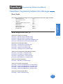
PowerPanel Models .................................................................................................................................... 5
Features .................................................................................................................................................. 6
PLCs Supported by PowerPanels .............................................................................................................. 7
PLC Cable Part Numbers ........................................................................................................................... 8
Programming Cable Part Number .............................................................................................................. 8
PowerPanel Programming Software .......................................................................................................... 9
Installing the Software .......................................................................................................................... 9
Chapter 2
Tutorial—Configure PLC ....................................................................................................................... 12
Tutorial—Create a Project ..................................................................................................................... 13
Step 1 ................................................................................................................................................ 13
Step 2 ................................................................................................................................................ 15
Step 3 ................................................................................................................................................ 22
Chapter 3
Project Setup .......................................................................................................................................... 26
Decide now if you want to work ON-LINE or OFF-LINE .................................................................... 26
Step 1 Project Information ................................................................................................................ 27
SELECT ACTION ................................................................................................................... 27
Edit Program OFF-LINE (Write to Panel Later) .................................................................... 27
Read Program from Panel and Edit OFF-LINE .................................................................... 29
Edit Program ON-LINE .......................................................................................................... 30
A QUICK REVIEW for “ENTER PROJECT INFORMATION” ............................................... 31
Step 2 Design Your Screens ............................................................................................................. 33
Step 3 Write Your Program to Panel ................................................................................................. 35
Chapter 4
Objects Menu .......................................................................................................................................... 38
Button Object ...................................................................................................................................... 41
Protection Tab .............................................................................................................................. 43
Visibility/Details Tab ..................................................................................................................... 45
Indicator Button Object ....................................................................................................................... 46
Radio Buttons ...................................................................................................................................... 48
Switch Object ...................................................................................................................................... 51
Step Switch Object .............................................................................................................................. 53
Tri-State Switch Object ....................................................................................................................... 55
i
Programming Software User Manual
Numeric Entry Object .......................................................................................................................... 57
Scaling Tab ................................................................................................................................... 59
Recipe Object ...................................................................................................................................... 61
Thumbwheel Object ............................................................................................................................ 64
Indicator Light Object .......................................................................................................................... 66
Numeric Display Object ...................................................................................................................... 68
Scaling Tab ................................................................................................................................... 70
Text Object .......................................................................................................................................... 71
Static Text ..................................................................................................................................... 71
Triggered Text .............................................................................................................................. 72
Lookup Text .................................................................................................................................. 74
Message Database ................................................................................................................ 75
Dynamic Text ................................................................................................................................ 76
Text Entry ..................................................................................................................................... 78
Clock Object ........................................................................................................................................ 80
Analog Clock ................................................................................................................................ 80
Digital Clock ................................................................................................................................. 81
Meter Object ........................................................................................................................................ 82
Alarms Tab .................................................................................................................................... 83
Digital Display Tab ....................................................................................................................... 84
Scaling Tab ................................................................................................................................... 85
Bar Graph Object ................................................................................................................................ 87
Digital Display Tab ....................................................................................................................... 88
Scaling Tab ................................................................................................................................... 89
Line Graph Object ............................................................................................................................... 90
Pen Tab ........................................................................................................................................ 91
XY Axis Tab .................................................................................................................................. 92
PID Faceplate Object .......................................................................................................................... 94
Legends Tab ................................................................................................................................. 96
Change Screen Object ....................................................................................................................... 97
Alarm History Object ........................................................................................................................... 99
System Objects ................................................................................................................................. 101
Increment/Decrement Hour ....................................................................................................... 101
Activate Screen Saver ............................................................................................................... 102
Adjust Contrast .......................................................................................................................... 104
Select Language ........................................................................................................................ 105
Multi-state Indicator ........................................................................................................................... 107
Message Tab .............................................................................................................................. 109
Bitmap Objects .................................................................................................................................. 115
Dynamic Bitmap ......................................................................................................................... 115
Bitmap Button ............................................................................................................................ 118
Multi-state Bitmap ...................................................................................................................... 121
Images Tab ........................................................................................................................... 123
Increment/Decrement Value Object ................................................................................................. 126
Increment/Decrement Value Tab ............................................................................................... 127
Multi-function Object ......................................................................................................................... 128
Operations Tab ........................................................................................................................... 129
Report Object .................................................................................................................................... 131
Messages Tab ............................................................................................................................ 132
Data Acquisition Objects ................................................................................................................... 138
Table View .................................................................................................................................. 138
Frequency Chart ........................................................................................................................ 140
Statistics ..................................................................................................................................... 142
ii
Programming Software User Manual
Chapter 5
Main Programming Screen ................................................................................................................. 146
Title Bar ............................................................................................................................................. 146
Main Menu Bar .................................................................................................................................. 146
Standard Tool Bar .............................................................................................................................. 147
Object Tool Bars ................................................................................................................................ 148
Basic Objects Tool Bar ............................................................................................................... 148
Text Objects Tool Bar ................................................................................................................. 149
System Objects Tool Bar ........................................................................................................... 149
Bitmap Objects Tool Bar ............................................................................................................ 150
Data Acquisition Tool Bar ........................................................................................................... 150
Draw Tool Bar .................................................................................................................................... 150
Panel Tool Bar ................................................................................................................................... 150
Status Bar .......................................................................................................................................... 151
3 Easy Steps Tool Bar ....................................................................................................................... 151
Programming Screen ........................................................................................................................ 152
Project Screens Explorer View ......................................................................................................... 152
Chapter 6
Reference
File Menu ........................................................................................................................................... 154
Edit Menu .......................................................................................................................................... 159
Screen Menu ..................................................................................................................................... 162
Objects Menu .................................................................................................................................... 166
Draw Menu ........................................................................................................................................ 167
Sizing a Bitmap in Symbol Factory ........................................................................................... 170
Panel Menu ....................................................................................................................................... 171
Setup Menu ....................................................................................................................................... 178
Tag Database ............................................................................................................................. 178
Tag Cross Reference ................................................................................................................. 181
Export Tags ................................................................................................................................ 182
Import Tags ................................................................................................................................. 183
Alarm Database ......................................................................................................................... 186
Export Alarms ............................................................................................................................. 188
Message Database .................................................................................................................... 189
Export Messages ....................................................................................................................... 191
Import Messages ....................................................................................................................... 192
Project Attributes ........................................................................................................................ 194
Project Description ..................................................................................................................... 205
Select PLC ................................................................................................................................. 205
Upgrade Firmware ..................................................................................................................... 206
Global Objects ........................................................................................................................... 208
Multi-Function ...................................................................................................................... 208
Data Acquisition - FIFO ....................................................................................................... 212
Edit Objects .......................................................................................................................... 214
Delect Objects ...................................................................................................................... 215
Window Menu .................................................................................................................................... 216
Help Menu ......................................................................................................................................... 217
Right Click Menus ............................................................................................................................. 218
Symbol Factory® ............................................................................................................................... 219
Appendix A Troubleshooting
Frequently Asked Questions (FAQs) ................................................................................................ A-2
iii
Programming Software User Manual
Troubleshooting ................................................................................................................................ A-5
PowerPanel Error Messages .......................................................................................................... A-15
PowerPanel Programming Software Error Messages ................................................................... A-16
Appendix B ASCII Characters
PowerPanel ASCII Characters ....................................................................................................... B-2
Appendix C
PLC Communications Setup ............................................................................................................ C-2
Appendix D
Assigned Ports in Panel Setup Mode ............................................................................................... D-2
INDEX
................................................................................................................................................ I-1
iv
Programming Software User Manual
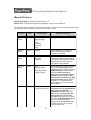
Manual Revisions
Manual Part Number: MAN-UTICW-M, Revision 4
Manual Title: PowerPanel Programming Software Version 4.0 User Manual
The following table provides you with update information. If you call technical support with a question about this manual, please be aware of the revision number.
Revision
Date
Effective Pages
Description of Changes
Original
Release
07/2001
Cover
Warning/Copyright
i–vi
1–160
Appendix A
Appendix B
Index
Original Release of Manual
Version 2.0
Release
02/2002
All pages
Software Release 2.0 — Changes to all
objects, new objects/features added.
Appendix C and D added.
Version 2.1
Release
02/2002
All pages
Appendix C
Appendix D
Software Release 2.1 — G*Square Series
and Q2Panel information added. Masking
option added to Multi-state Bitmap and Multistate Indicator object. Switch to Screen
option added to Project Attributes.
Version 2.2
Release
05/2002
Cover
Warning/Copyright
v
1–200 (pages added,
changes to pages)
Software Release 2.2 — Math Logic object
name changed to Multi-function object.
Copy Screen selection added to File Menu
. COM Configuration selection added to
Panel Menu. Objects Overlapping
Warning option and Overlapping Objects
information added to Edit Menu. Read
Alarm History/Count, Monitor Tags, Read
Linegraph from Panel features added to
Panel Menu. 15-inch G*Square Panel
selection added. 8- and 10-inch Q2Panel
selection added.
Version 2.5
10/2002
Cover
1—200 (various changes)
Software Release 2.5 — added support for
Uni-Telway Driver, CTC 2600-2700 Binary
driver, generic DeviceNet driver.
Add/Edit Alarm changed to allow Alarm
State selections of In Range, Equal, Not
Equal, Greater Than, and Less Than.
Line Graph object allows you to plot points
from right to left. Multi-state Bitmap Object
allows you to mask number based
bitmap/message. Change Screen object
now allows you to enter a 0 to change to
previoulsy viewed screen.
v
Programming Software User Manual
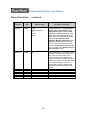
Manual Revisions — continued
Revision
Date
Effective Pages
Description of Changes
Version 3.0
12/2002
Cover
Warning/Copyright
i–vi
1–220
Index
Software Release 3.0 — Data Acquisiton
Objects added. Global Objects added.
Import Messages option added. Initial
Tag Value and Retentive Initial Tag Value
option added. Copy Screens option now
allows copying tags. Port assignment tab
added to Project Attributes. Allow
Stretching, Maintain Aspect Ratio option
available for all bitmap objects. Bitmaps
larger than 64K or 640 x 480 can now be
imported. Decimal Point control by a tag
is now an option for the Numeric Entry and
Numeric Display objects.
Version 4.0
05/2003
All
Software Release 4.0 — Some of the major
additions to this exttensive software revision
are: Dual PLC Driver Support added.
Expression Tags added. Duplicate Tags
option and Search and Replace test option
added to Tag Database. Touch PRLS, Alarm
List, Screen List Selector, Control List
Selector objects added. Notification and
Handshake Flags added to Numeric Entry
Objects.
vi
Programming Software User Manual
EU Information
The G*Square Series PowerPanel is manufactured in compliance with European Union (EU) Directives and carries the CE mark. The G*Square Series PowerPanel has been tested under CE Test
Standard #EN55011, and is listed under UL File #E209355. The following information is provided to
comply with EU documentation requirements.
Please NOTE: Products with CE marks perform their required functions safely
and adhere to relevant standards as specified by EU Directives provided they
are used according to their intended purpose and that the instructions in this
manual are adhered to. The protection provided by the equipment may be
impaired if this equipment is not used in accordance with this manual. Only
replacement parts supplied by UTICOR Technology, L. P. or its agents should
be used.
Technical
Support
Consult PowerPanel Programming Software Help or you may find answers to
your questions at our web site @ www.uticor.net. If you still need assistance,
please call our technical support at 1-800-832-3647 or FAX us at 1-563-3599094.
SELV Circuits
All electrical circuits connected to the communications port receptacle are rated
as Safety Extra Low Voltage (SELV).
Environmental
Specifications
Operating Temperature
G*Square and Q2Panel 6" Monochrome/6" Color .................. 0 to 45 °C
G*Square and Q2Panel 8" Color ............................................ 0 to 40 °C
G*Square 10" Color ................................................................. 0 to 50 °C
G*Square 15" Color ................................................................. 0 to 45 °C
Storage Temperature
G*Square and Q2Panel 6" Mono ...................................... –20 to +60 °C
G*Square and Q2Panel 6" Color ...................................... –25 to +60 °C
G*Square 8" Color ............................................................. –20 to +60 °C
Q2Panel 8" Color .............................................................. –25 to +60 °C
G*Square 10" Color ........................................................... –25 to +60 °C
G*Square 15" Color ........................................................... –25 to +60 °C
Operating Humidity ................................... 10–95% R.H., noncondensing
Air Composition .......................................... No corrosive gases permitted
Preventative
Maintenance
and Cleaning
No preventative maintenance is required. The PowerPanel touchscreen should
be cleaned as needed with warm, soapy water. See the PowerPanel Hardware
User Manual (P/N MAN-UTICW-001) for a list of compatible/incompatible chemicals and compounds.
vii
Programming Software User Manual
This page intentionally left blank.
viii
Introduction
1
In this chapter....
— Manual Organization
— Introduction
— What you need to get started
— Need HELP?
— Models
— Features
— PLCs Supported by PowerPanels
— PLC Cable Part Numbers
— Programming Cable Part Number
— PowerPanel Programming Software Installation
Programming Software User Manual
Introduction
Manual Organization
The PowerPanel Programming Software User Manual is arranged in chapters. A description of key information
contained in each chapter is provided below.
Chapter
1
Introduction
Provides Manual Organization, and lists what you need to get started, hardware and
software. Discusses how to get help with questions or problems you might encounter through Onscreen Help and Technical Support. Provides you with a table listing
the various models, and their special features. Lists the important features of all
PowerPanels. Lists the PLCs supported by the panels, by brand, model and
protocol. Lists the part numbers for PLC cables and the programming cable. Tells
how to install programming software.
2
Tutorial
Provides instructions to create an example (or “demo”) project. Discusses how to
configure a PLC ladder logic program to use with the demo project. Takes you
through the steps necessary to create a PowerPanel project using the programming
software. Shows you how to transfer the project to the panel, and testing the
project once transferred.
3
4
5
A
2
Description
Project Setup
Discusses ON-LINE and OFF-LINE configuration options. Tells you how to set up a
project by entering project information (Step 1). Discusses screen design (Step 2),
and how to transfer the project to the panel (Step 3).
Objects
Provides step-by-step instructions for configuring each of the PowerPanel objects.
Reference
Provides more details on menu commands. Takes you through the main menu bar
item by item, command by command, with instructions. Contains information on the
various tool bars and the status bar. Describes right click menus
Appendix A Troubleshooting
Aids in diagnosing problems you might encounter when installing or operating your
PowerPanel. Provides steps to take to isolate and correct problems. Lists panel
error messages, programming software error messages, and PLC Driver Error
messages.
B
Appendix B Characters
Provides a list of the ASCII Characters supported by the PowerPanel. This
information may be useful when creating a Text Entry or Dynamic Text object.
C
Appendix C PLC Communications Setup
Provides instructions on how to set up most PLC Types to communicate with the
PowerPanel.
D
Appendix D Assigning Ports in Panel Setup Mode
Provides instructions on how to assign the COM1 and PLC Ports on the PowerPanel.
Phone: 1-563-359-7501 • Fax: 1-563-359-9094 • www.uticor.net
MAN-UTICW-M — V4.0
Programming Software User Manual
Introduction
PowerPanel
Don’t worry — you won’t be bouncing back and forth between them —
and we’ll always let you know exactly where the information is that you
will need for the next step.
PowerPanel
These manuals will take you through the steps necessary to get your
PowerPanel up and running in the shortest possible time. Although your
familiarity with programmable graphic operator interface devices will
determine how quickly you move through the steps — it’s as easy as 1
— 2 — 3.
Install the PowerPanel using
the instructions in the
Hardware Manual.
Program the PowerPanel
using the instructions in this
Software Manual.
What you need to get started....
Hardware
•
•
•
•
•
PowerPanel G 2 Series: G*2 6" Monochrome, G*2 6" Color,
G*2 8" Color, G*2 10" Color, and G*2 15" Color
Q2Panels: Q*2 6" Monochrome, Q*2 6" Color, Q*2 8" Color,
Q*2 10" Color
24 Volt DC Power Supply
RS-232C Programming Cable (P/N CBL-UTICW-009)
RS-232C or RS-422A/485A PLC Interface Cable (see page 8
for part numbers)
PC requirements:
— IBM or compatible PC (Pentium 166 MHZ or better)
with a mouse and separate serial port
— VGA display with at least 800 x 600 resolution
(1024 x 768 recommended)
— Standard Windows 98/NT4.0/2000/ME/XP Professional/
XP Home® Requirements
— CD ROM Drive
Software
•
MAN-UTICW-M — V4.0
PowerPanel Programming Software Version 4.0 (P/N ACCUTICW-CD)
Phone: 1-563-359-7501 • Fax: 1-563-359-9094 • www.uticor.net
3
Introduction
Introduction
There are two manuals that you will need for installation — this manual,
the PowerPanel Software User Manual, Version 4.0 and the PowerPanel
Hardware User Manual (P/N MAN-UTICW-001) shipped with your
PowerPanel.
Programming Software User Manual
Introduction
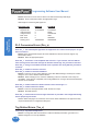
Need HELP?
PLEASE NOTE: The Troubleshooting section (Appendix A) should
be able to help you with most problems you might encounter.
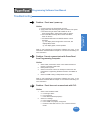
Onscreen HELP
One of the most important features of the PowerPanel Programming
Software is the availability of context sensitive onscreen help. To access
the Help windows, simply press the F1 function key while on the topic
where you need help. For example, if you need help while working with
screens, press the F1 function key while in that area and a popup window
will be displayed. You may also click on the Help button located at the
bottom of most dialog boxes to go to the help topic.
Fly-Over HELP
When the mouse cursor comes to rest over any tool bar or object button
for a short while, a small window will appear containing a brief description
of the function of that particular button. The window will disappear as
soon as the cursor has been moved off the button.
PLC HELP
If you need help with the PLC to PowerPanel Interface, consult the
PowerPanel Programming Software Help. Each PLC Driver has a Help
Topic that lists the error messages and provides an explanation for each.
Also provided are PLC to PowerPanel wiring diagrams.
Technical Support
Although most questions can be answered with PowerPanel HELP or
the manuals, you may find answers to your questions in the operator
interface section of our web site @ www.uticor.net. If you still need
assistance, please call our technical support at 1-800-832-3647 or FAX
us at 1-563-359-9094.
4
Phone: 1-563-359-7501 • Fax: 1-563-359-9094 • www.uticor.net
MAN-UTICW-M — V4.0
Programming Software User Manual
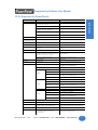
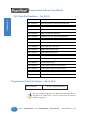
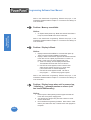
PowerPanel Models
The PowerPanel is available in a variety of models to suit your application.
Refer to the table below for a list of model descriptions and some important
options that are available.
G2 Series PowerPanels
G*2 Model
Description
User
Memory
Field
Expandable
User RAM?
Nonvolatile Flash
Backup Card Option
for Program Backup?
PLC Drivers
Supported? *
6" Monochrome
A-B Data
Highway Plus
Panel
6" STN Color
A-B Remote I/O
Yes —
to 1 MEG
Panel
512K
8" STN Color
Panel
DeviceNet I/O
Yes
All
ModBus Plus
10" TFT Color
Ethernet/IP
Panel**
15" TFT Color
Panel
*
Option Cards
Available
1 MEG
Profibus-DP
Yes —
to 1.5 MEG
A list of PLC Drivers supported is provided on page 7 of this manual.
**
The 10" TFT Color Model is offered in two sizes. One that has the same footprint as the previous
version of the PowerPanel and the new PowerPanel standard size (smaller than previous version).
Q2Panels
Q*2 Model
Description
User
Memory
Field
Expandable
User RAM?
6" Monochrome
Panel
No
6" STN Color
Panel
No
8" STN
Color Panel
512K
Nonvolatile Flash
Backup Card Option
for Program Backup?
PLC Drivers
Supported? *
Option Cards
Available
A-B Data
Highway Plus
A-B Remote I/O
Yes
All
DeviceNet I/O
ModBus Plus
8" TFT
Color Panel
Yes —
to 1 MEG
10" TFT
Color Panel
*
Ethernet/IP
Profibus-DP
A list of PLC Drivers supported is provided on page 7 of this manual.
MAN-UTICW-M — V4.0
Phone: 1-563-359-7501 • Fax: 1-563-359-9094 • www.uticor.net
5
Introduction
Introduction
The PowerPanel is an intelligent, programmable, flat panel display. It
has been designed to interchange and display graphical data from a
PLC by merely viewing or touching the screen.
Programming Software User Manual
Features
Introduction
The following is a list of important features for the PowerPanels:
6
•
Pre-built panel components for easy screen design
•
Special parts, such as: Toggle Switch, Slide Switch, Selector Switch, Throw
Switch, Thumbwheel Object, Meters, PID Faceplates, and Analog Clock
•
Flash based design for easy firmware upgrade
•
Field expandable user RAM (not available with all models)
•
Nonvolatile flash card option for user program backup
•
Color models support 128-color palette for components and bitmaps
•
16 shades of gray on monochrome models
•
Multiple languages (up to 9)
•
Two communications ports — Computer (RS-232C or RS-422A) and PLC
(RS-232C, RS-422A, or RS-485A)
•
Up to 999 screens
•
Built-in clock and calendar or reference the PLC clock
•
Built-in soft keypad for numeric and alphanumeric entry
•
Password Protection for every touch object
•
Passwords for up to 8 definable user groups
•
16 level undo and redo
•
Import bitmaps
•
Serial Printer support
•
40-character tag names allow you to use meaningful names for PLC
memory locations instead of cryptic PLC addresses
•
Expressions tags
•
Data Acquisition and Global objects
Phone: 1-563-359-7501 • Fax: 1-563-359-9094 • www.uticor.net
MAN-UTICW-M — V4.0
Programming Software User Manual
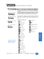
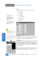
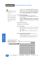
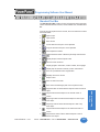
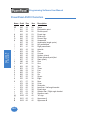
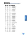
PLCs Supported by PowerPanels
M odel
P ro to c o ls S u p p o r te d
M i c ro lo g i x 1 0 0 0 /1 2 0 0 /1 5 0 0 ,
S L C 5 0 0 , 5 /0 1 ,/0 2 ,/0 3
D H 4 8 5 /A IC /A IC +
S L C 5 /0 4 , P L C 5
D H + (O p ti o n C a rd )
M i c ro lo g i x 1 0 0 0 , 1 2 0 0 a n d 1 5 0 0
S L C 5 /0 3 , /0 4 , /0 5 (w i th D F 1 )
D F 1 H a lf D up le x ; D F 1 F u ll D u p le x
PLC 5
DF1
P L C 2 , 3 , a nd 5
R e m o te I/O (D H + O p ti o n C a rd )
U n i d ri v e 2 -w i re , 4 -w i re
B i n a ry
C o n tro l Te c h no lo g y
C o rp o ra ti o n (C T C )
C TC 2 6 0 0 , 2 7 0 0 , a nd 5 1 0 0
C T C B i na ry
D e vic e N e t
D e v i c e N e t I/O
G e ne ri c D e v i c e N e t I/O (O p ti o n C a rd )
E th e rn e t
E th e rn e t/IP
G e ne ri c E th e rne t/IP (O p ti o n C a rd )
G e n e ra l E le c tri c
9 0 /3 0 a n d 9 0 /7 0
V e rs a m a x
SNPX
SNP
M its u b i s h i
F X S e ri e s (a ll)
D i re c t
M o d ic o n
9 8 4 C P U , Q u a n tu m 1 1 3 C P U
A E G M o d i c o n M i c ro S e ri e s 11 0 C P U :
3 1 1 -x x , 4 1 1 -x x , 5 1 2 -x x , 6 1 2 -x x
M o d b us R TU
C o n tro l Te c h ni q u e s
9 8 4 S e ri e s , Q ua n tu m S e rie s
M o d b u s P lu s (O p ti o n C a rd )
O m ro n
C 200, C 500
H o s t L i nk
P ro fi b u s
P ro fi b us -D P
G e ne ri c P ro fi b us -D P (O p ti o n C a rd )
D L05
K -S e q u e n c e ; D i re c tN e t;
M o d B u s (K o y o a d d re s s i n g )
D i re c tL o g i c
D L105
Introduction
Introduction
P L C B ra n d
A lle n -B ra d le y
K -S e q u e n c e
D 2 -2 3 0
K -S e q u e n c e
D 2 -2 4 0
K -S e q u e n c e ; D i re c tN e t
D 2 -2 5 0
K -S e q u e n c e ; D i re c tN e t;
M o d B u s (K o y o a d d re s s i n g )
D 2 -2 4 0 /2 5 0 D C M
D i re c tN e t
D 3 -3 3 0 /3 3 0 P
D i re c tN e t
D 3 -3 4 0
D i re c tN e t
D 3 -3 5 0
K -S e q u e n c e ; D i re c tN e t;
M o d B u s (K o y o a d d re s s i n g )
D 3 -3 5 0 D C M
D i re c tN e t
D 4 -4 3 0
K -S e q u e n c e ; D i re c tN e t
D 4 -4 4 0
K -S e q u e n c e ; D i re c tN e t
D 4 -4 5 0
K -S e q u e n c e ; D i re c tN e t;
M o d B u s (K o y o a d d re s s i n g )
D L205
D L305
D L405
A ll w i th D C M
D i re c tN e t
S ie m e n s
S i e m e ns S 7 M P I A d a p te r
3964R
S q u a re D S y m a x
3 0 0 S e ri e s C P U , 4 0 0 S e ri e s C P U
S ym a x
Te xa s Ins tru m e n ts
T I5 X 5 S e ri e s —
T I 5 0 5 , T I5 4 5 -1 1 0 2 , T I5 4 5 -1 1 0 4
T B P (Tra ns p a re nt B y te P ro to c o l) o r
N IT P (N o n-In te lli g e n t Te rm i n a l P ro to c o l)
U ni -Te lw a y
Te le m e c a n i q ue T S X 3 7 M ic ro
U N I-T E (V e rs i o n 1 .1 )
O th e r
H 2 - W i n P L C (T h i n k & D o V 6 .3 , T h i n k
& D o S tu d i o ,c h e c k fo r v e rs i o n
c o m p a ti b i li ty )
M o d b u s R T U (s e ri a l p o rt)
MAN-UTICW-M — V4.0
Phone: 1-563-359-7501 • Fax: 1-563-359-9094 • www.uticor.net
7
Programming Software User Manual
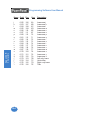
Introduction
PLC Cable Part Numbers — 3m (9.8 ft.)
Part Number
Cable Description
CBL-UTICW-001
GE 90/30 and 90/70 15-pin Dsub port (RS-422A)
CBL-UTICW-002
A-B SLC 5/03/04/05 DF1 port (RS-232C)
CBL-UTICW-003
A-B PLC5 DF1 port (RS-232C)
CBL-UTICW-004
A-B SLC DH485 port (RS-485A)
CBL-UTICW-005
A-B MicroLogix 1000, 1200 & 1500 (RS-232C)
CBL-UTICW-006
Mitsubishi FX Series 25-pin port (RS-422A)
CBL-UTICW-007
Mitsubishi FX Series 8-pin MINI-DIN (RS-422A)
CBL-UTICW-008
Omron C200, C500 (RS-232C)
CBL-UTICW-010
ModBus with RJ45 (RS-232C)
CBL-UTICW-011
Modicon ModBus (RS-232C)
CBL-UTICW-012
Siemens S7 MPI Adaptor (RS-232C)
CBL-UTICW-013
Omron 9-pin Programming Port (RS-232C)
CBL-UTICW-014
GE Versmax (RS-232C)
CBL-UTICW-016
Control Technics Unidrive 4-wire (RS-485A)
CBL-UTICW-017
Control Technics Unidrive 2-wire (RS-485A)
CBL-UTICW-019
Control Technology Corp phone type 6-position (RS-232C)
CBL-UTICW-021
Uni-Telway Telemecanique TSX 37 Micro (RS-485A)
Programming Cable Part Number — 2m (6.56 ft.)
CBL-UTICW-009
RS-232 Programming Cable
See the PowerPanel Hardware User Manual (P/N MAN-UTICW-001),
Appendix A for cable pinouts, or use the PowerPanel Programming
Software Help Topics.
8
Phone: 1-563-359-7501 • Fax: 1-563-359-9094 • www.uticor.net
MAN-UTICW-M — V4.0
Programming Software User Manual
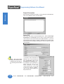
PowerPanel Programming Software
(See page 3 for requirements.)
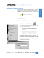
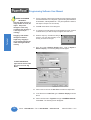
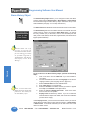
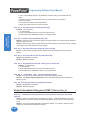
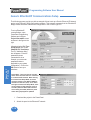
Installing the Software
Perform the following steps to install the PowerPanel Programming
Software onto your PC.
•
Place the CD into your CD ROM drive.
•
The CD should automatically start the install program, if it does
not, perform the following 2 steps:
1.
From Windows click on the Start Button, and then
click on Run from the menu. The Run dialog box
will pop up.
2.
At the prompt type D:\ (or your CD ROM drive)
setup.exe or click on the Browse Button and find
the Setup.exe file for PowerPanel Programming
Software.
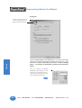
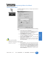
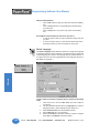
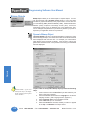
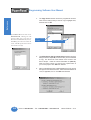
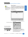
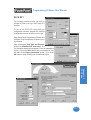
•
Click on the OK button to begin the installation. The
PowerPanel Programming Software Installation Screen will
appear.
•
Follow the onscreen prompts to load the software. (Installation
screens are shown, next page.)
Installation Screens
MAN-UTICW-M — V4.0
Phone: 1-563-359-7501 • Fax: 1-563-359-9094 • www.uticor.net
9
Introduction
Introduction
PowerPanels are configured with software running on an IBM or
compatible personal computer. This software is available through Uticor
Technology, L. P., part number MAN-UTICW-CD. The panel can be
configured on-line or off-line.
Introduction
Programming Software User Manual
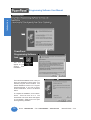
➥
➡
PowerPanel
Programming Software
Icon
➥
This icon will
appear on your
desktop
after
installation.
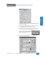
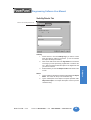
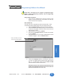
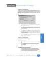
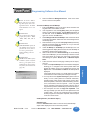
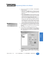
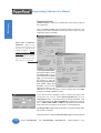
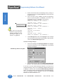
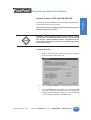
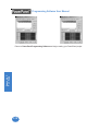
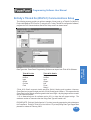
➡
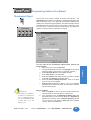
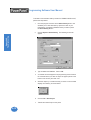
This is the final installation screen. Here you
select the destination folder where your
software program will be installed. The
default destination location is C:\ Program
Files\PowerPanel. If you wish to select
another destination, click on the Browse
button.
To complete the installation, click on Next>
button. That’s all there is to it! The
PowerPanel Icon shown above will appear
on your desktop. Simply click on it to open
the Programming Software!
10
Phone: 1-563-359-7501 • Fax: 1-563-359-9094 • www.uticor.net
MAN-UTICW-M — V4.0
Tutorial
In this chapter....
— Configure a PLC
— Create a Project
2
Programming Software User Manual
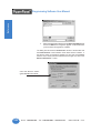
Tutorial — Configure PLC
For the purposes of this Tutorial, we will be using an Allen-Bradley SLC
500 Programmable Logic Controller (PLC), with Full Duplex Protocol (one
PLC only). To configure the PLC we are using RSLogix® Programming
Software. The purpose of this part of the tutorial is to show you how to
configure your PLC to communicate with a PowerPanel.
Connect the programming PC to the Alllen-Bradley SLC 500 PLC. With
RSLogix Programming Software running on your PC, perform the following
steps.
Tutorial
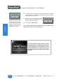
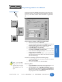
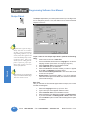
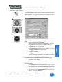
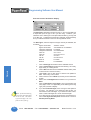
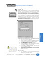
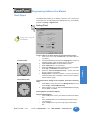
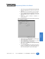
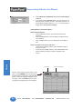
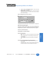
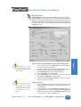
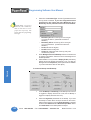
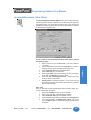
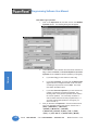
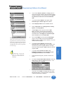
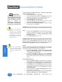
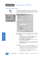
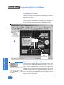
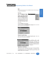
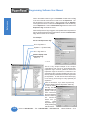
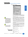
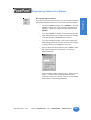
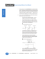
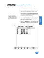
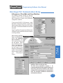
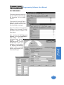
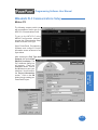
1.
Enter the Ladder Logic as shown in the example (below, left).
These PLC locations will be used by Tags that you will create in
the PowerPanel Programming Software.
2.
Configure Channel 0, System, as shown
in the graphic (below, right).
3.
Save this program and transfer it to the
PLC. Place the PLC in Run Mode.
4.
Exit RSLogix Programming Software.
For this tutorial, we will be connecting the
panel to DF1 Port of an Allen-Bradley SLC 500
with Full Duplex Protocol. These are the
settings that will be used when setting up the
panel communications.
You have now configured the PLC to
communicate with a PowerPanel Project that
you will create in the next section of this
tutorial.
12
Phone: 1-563-359-7501 • Fax: 1-563-359-9094 • www.uticor.net
MAN-UTICW-M — V4.0
Programming Software User Manual
Tutorial — Create a Project
Introduction
The following is a project tutorial. You’ve already configured your PLC to
work with the PowerPanel project you will be creating in this section. Now
we’ll take you through the process of creating a new project, placing objects
on the screen, and transferring a project to the PowerPanel. This should
help familiarize you with the PowerPanel Programming Software
environment.
Let’s assume you have the programming software installed on your PC (if
you don’t, go back to page 9 and install now). Connect the PowerPanel
to your PC using the P/N CBL-UTICW-009 cable. Connect the PowerPanel
to your PLC using the appropriate panel to PLC cable.
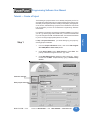
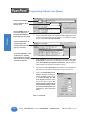
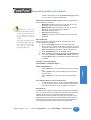
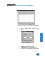
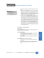
In Step 1, Project Information, you will be setting up your project by
entering project information.
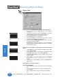
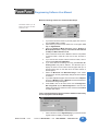
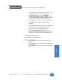
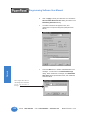
1.
From the Project Information screen, click on the Edit Program
OFF-LINE (Write to Panel Later) button.
2.
Under Project Name, type in Demo Project 1. Press Enter. The
primary PowerPanel Program file has a “.prp” suffix.
3.
Under Start Editing Screen, leave the screen number as 1. Click in
the field next to Name. Replace Scr1 by typing in Numeric Entry
Screen.
Click here to begin.
Enter project name here.
MAN-UTICW-M — V4.0
Phone: 1-563-359-7501 • Fax: 1-563-359-9094 • www.uticor.net
13
Tutorial
Step 1
Programming Software User Manual
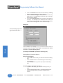
Enter Screen Number.
Type in “Numeric Entry
Screen” here.
Tutorial
Click on DOWN arrow to
view Panel Types and
select the Part Number/
Model Type you are using.
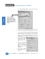
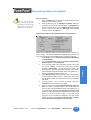
4.
Click on the DOWN arrow to the right of the Panel Type field to view
choices. Select the Panel Type you are using. In this Demo Program
we are using the G*2 8" Color 640x480.
5.
Under First PLC, click on the DOWN arrow to the right of PLC Type
and Protocol to view the list. For the purpose of this Demo Program,
select Allen-Bradley SLC 500 DF1 (Full Duplex). (We are using an
Allen-Bradley SLC 500 with Full Duplex Protocol.)
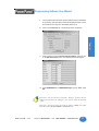
6.
Leave the box next to Second PLC unchecked. For the purposes of
this tutorial, we will only be configuring the project for one PLC.
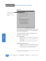
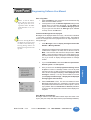
7.
Click on the View/Edit PLC Com
Setup to edit the PLC Attributes.
Set the attributes to match those
in the Allen Bradley SLC 500
(Full Duplex) attributes dialog
box shown below. Click OK.
(These settings must match the
PLC Com Port settings. Check
your PLC User Manual for port
settings for your particular
PLC.)
Click on DOWN arrow to
view PLC Type and
Protocol and select the
type you are using.
To set PLC Attributes, click
on this button. A dialog
box particular to the type
PLC and Protocol you have
selected will appear.
Step 1 is complete!
14
Phone: 1-563-359-7501 • Fax: 1-563-359-9094 • www.uticor.net
MAN-UTICW-M — V4.0
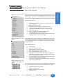
Programming Software User Manual
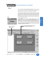
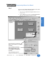
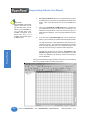
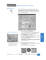
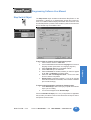
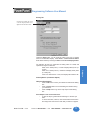
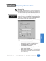
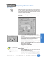
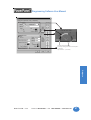
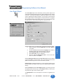
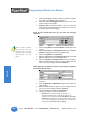
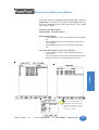
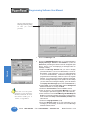
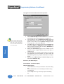
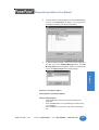
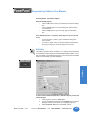
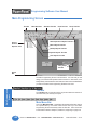
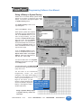
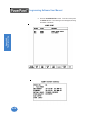
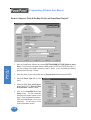
Step 2
The PowerPanel Programming Software working environment is shown
below. Toolbars provide easy access to all major programming functions
and features. The objects shown below represent the touch buttons and
displays that will be transferred to the panel and communicate with the
PLC when this tutorial is completed.The Main Programming Screen opens
with the toolbars shown below.
Project Screens
Explorer View
MAN-UTICW-M — V4.0
These are the objects you are about
to configure in this tutorial.
Phone: 1-563-359-7501 • Fax: 1-563-359-9094 • www.uticor.net
15
Tutorial
PROGRAMMING TIP: Before you begin placing objects on the
programming screen, click on Edit > Default Tag Data Type and select
SIGNED_INT_16. By selecting the default data type as SIGNED_INT_16
here, you won’t have to select it later when configuring the tag details for
the objects. Please note, however, that if the data type for an object requires
something other than the default data type you have selected, it will show
the required data type (i.e., Discrete).
Introduction
You are now ready for Step 2, Design Your Screens. In Step 2 we will
place 4 objects on the screen. You have already configured your PLC
ladder logic for this Demo Project in the first part of the tutorial.
Tutorial
Programming Software User Manual
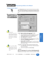
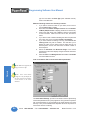
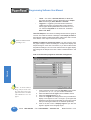
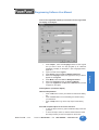
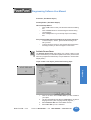
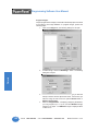
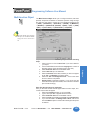
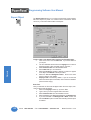
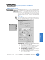
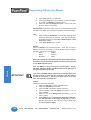
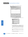
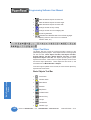
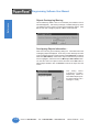
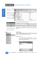
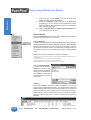
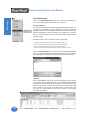
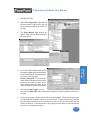
1.
Click on Objects>Numeric Entry. The following screen will appear.
2.
Click on the box in front of Label Text to activate the object label.
3.
In the field next to Label Text, type in Numeric Entry as shown above.
4.
The object defaults to Use single tag for both Entry and Display
purpose (check mark in box in front of phrase). Leave this selected.
5.
Click in the field next to Entry and Display Tag and type in the name
NUMERIC ENTRY. Press Enter. The following screen will appear.
6.
Under Select Tag Type,
leave PLC 1: AllenBradley SLC 500....
selected as shown to the
right.
7.
In the field next to Address
String, type in N7:0, as
shown in the example to the
right.
Select
SIGNED_INT_16 for the
Data Type.
8.
Leave Initial Value/
Retentive Flag unchecked.
Click OK.
There are many more
features that you may
program, such as, Position
of Label, Color of Text and
Background, and Language,
but for the purposes of this
tutorial, we will use the
Defaults.
16
Phone: 1-563-359-7501 • Fax: 1-563-359-9094 • www.uticor.net
MAN-UTICW-M — V4.0
Programming Software User Manual
For the purposes of this tutorial, we have opted to leave the remainder
of the options under the object’s General tab (Range Check, Format
and Decimal Point Tag) set to the default (leave as is).
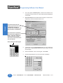
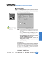
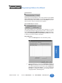
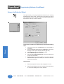
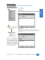
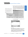
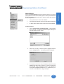
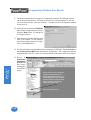
10. Click on the Protection tab. The following screen will appear.
Introduction
9.
Tutorial
11. Click on the box in front of Password Protect Object, and then click
on the Edit Passwords button. The following screen will appear.
12. Under PASSWORD for the GROUP, Managers, type in “1234”. Click
OK.
Please Note: Once the password is entered for Managers, all objects that you
configure for Protection at the “Managers” level, will now require the Password
“1234”.
Please Note: You can also assign passwords by clicking on Setup in the Main
Menu Bar and then Project Attributes > Passwords (tab).
MAN-UTICW-M — V4.0
Phone: 1-563-359-7501 • Fax: 1-563-359-9094 • www.uticor.net
17
Tutorial
Programming Software User Manual
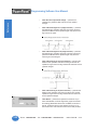
NOTES ON RESIZING
AN OBJECT:
Drag the object to move, or
drag a handle to resize, the
object. The pointer
changes to a four-way
arrowhead (for moving), or
a two-way arrow (for
resizing).
13. For the purposes of this tutorial, we will leave the remaining options
set to their defaults or not configured. (Ignore Scaling tab, Notification
& Handshake, Visibility/Details tab — they are explained in detail for
this object in Chapter 4 of the manual.)
Dragging a side handle
changes the width or
height only; dragging a
corner handle changes the
width and height simultaneously.
16. Grab the object by a handle and drag to
resize it until the label displays in its
entirety, as shown to the right.
14. Click OK at the bottom of the dialog box.
15. A crosshair cursor will appear on the programming screen. Position
crosshair where you want the object to appear, and click once.
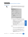
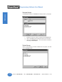
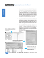
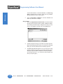
17. Next, we’ll create a Numeric Display object. Click on Objects >
Numeric Display. The following dialog box will appear.
To EDIT TAG DETAILS,
right click the mouse while
the cursor is on the Tag
Name.
18. Click on the box in front of Label Text to activate the object label.
19. In the field next to Label Text, type in Numeric Display as shown
above.
20. Click in the field next to Tag Name and type in NUMERIC DISPLAY.
Press Enter. The following screen will appear.
18
Phone: 1-563-359-7501 • Fax: 1-563-359-9094 • www.uticor.net
MAN-UTICW-M — V4.0
Programming Software User Manual
Introduction
Tutorial
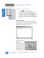
21. Under Select Tag Type, leave PLC 1: Allen-Bradley SLC 500....
selected as shown above.
22. In the field next to Address String, type in N7:1, as shown above.
Select SIGNED_INT_16 as the Data Type. Click OK.
23. A crosshair cursor will appear on the programming screen. Position
crosshair where you want the object to appear, and click once.
24. Grab the object by a handle and drag to
resize it until the label displays in its
entirety, as shown to the right.
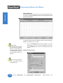
25. Next, we’ll create a Button object. Click on Objects > Buttons.
The following dialog box will appear.
MAN-UTICW-M — V4.0
Phone: 1-563-359-7501 • Fax: 1-563-359-9094 • www.uticor.net
19
Programming Software User Manual
26. Click on the box in front of Label Text to activate the object label.
27. In the field next to Label Text, type in Button.
Tutorial
28. Click in the field next to Tag Name and type in BUTTON OBJECT.
Press Enter. The following screen will appear.
29. Leave PLC 1: Allen-Bradley SLC 500 DF1... selected.
30. In the field next to Address String, type in B3:0/0, as shown above.
The Data Type will remain as DISCRETE. Click OK.
31. A crosshair cursor will appear on the programming screen. Position
where you want the object to appear (under the Numeric Entry object),
and click once.
32. Grab the object by a handle and drag to
resize it until the label displays in its entirety,
as shown to the right.
20
Phone: 1-563-359-7501 • Fax: 1-563-359-9094 • www.uticor.net
MAN-UTICW-M — V4.0
Programming Software User Manual
Introduction
33. Next, we’ll create an Indicator Light object. Click on Objects >
Indicator Lights. The following dialog box will appear.
Tutorial
34. Click on the box in front of Label Text to activate the object label.
35. In the field next to Label Text, type in Indicator Light as shown
above.
36. Click in the field next to Tag Name and type in INDICATOR LIGHT.
Press Enter. The following screen will appear.
37. Leave PLC1: Allen-Bradley SLC 500 DF1.... selected under Select
Tag Type.
38. In the field next to Address String, type in B3:1/0, as shown above.
The Data Type will remain as DISCRETE. Click OK.
MAN-UTICW-M — V4.0
Phone: 1-563-359-7501 • Fax: 1-563-359-9094 • www.uticor.net
21
Programming Software User Manual
Tutorial
32. A crosshair cursor will appear on the programming screen. Position
the crosshair where you want the object to appear (under the Numeric
Display object), and click once.
To select an object on the
screen, move your cursor
over the object and a line will
appear around the object to
highlight it, click the left
mouse button to select.
33. Grab the object by a handle and drag to
resize it until the label displays in its
entirety, as shown to the right.
34. Click on File > Save Project.
You’ve just completed Step 2, Design Your Screens! Now we will
transfer Demo Project 1 to the PowerPanel.
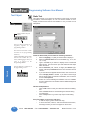
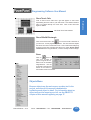
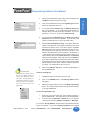
The PowerPanel is shipped with a bitmap
program installed. The image shown to the
left will display on the PowerPanel screen
upon initial power-up. The first project you
transfer to the panel will replace this bitmap
program!
22
Phone: 1-563-359-7501 • Fax: 1-563-359-9094 • www.uticor.net
MAN-UTICW-M — V4.0
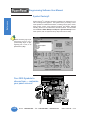
Programming Software User Manual
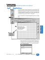
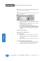
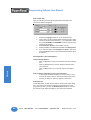
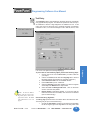
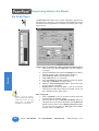
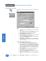
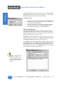
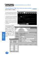
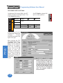
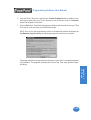
Step 3
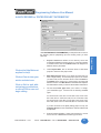
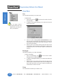
1.
Click on the 3 button (Write Your Program to Panel) as shown in
the graphic below.
2.
Click on the Start button at the bottom of the Write Program to Panel
dialog box to begin transferring the project to the panel.
Introduction
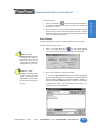
You are now ready for Step 3, Write Your Program to Panel. Demo
Project 1 should look similar to that shown below.
Tutorial
Click on 3, Write Your
Program to Panel
This screen will appear
Project Information is provided here.
Make sure the information is correct before
proceeding.
Ethernet/COM Port is shown here.
Click on the Configuration button to
choose COM Port. Make sure the
correct COM port is selected before
proceeding.
Click on Start button to write the
program to the PowerPanel.
MAN-UTICW-M — V4.0
Phone: 1-563-359-7501 • Fax: 1-563-359-9094 • www.uticor.net
23
Tutorial
Programming Software User Manual
3.
Your user program, Demo Project 1, should now be written to the
PowerPanel, and the screen you have created should be displayed
on the panel.
4.
Panel Information will be updated with information it receives from
establishing a link with the panel and the PLC.
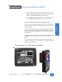
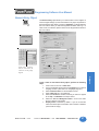
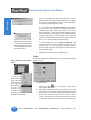
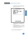
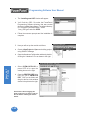
5.
To test the link, press the Numeric Entry button on your PowerPanel
panel screen. A popup keypad similar to the one shown to the left
should display.
6.
Enter the Password “1234” on the keypad. Press Enter.
7.
Another keypad similar to the one shown below will display.
The Panel to PLC Link will
display a green dot next to the
“Connected” message to
indicate that a link between the
panel and PLC is established.
Panel Information will display
the Total and Free Memory in
Bytes. It will also display the
Firmware Revision number —
the revision of the PowerPanel
internal software.
Enter password on this keypad.
24
Phone: 1-563-359-7501 • Fax: 1-563-359-9094 • www.uticor.net
MAN-UTICW-M — V4.0
Programming Software User Manual
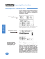
Enter a number on the keypad by pressing the number keys. Press
Enter. The keypad will disappear and the number you entered should
appear on the Numeric Display on your panel screen.
9.
Press the Button on your panel screen. It will change from Off to
On. The Indicator Light should change from Off to On, also.
Introduction
8.
You’ve just completed Step 3, Write Your Program to Panel!
This simple tutorial has taken you through the major steps to creating a
working link between your application and a PowerPanel. Of course,
there are almost unlimited capabilities for creating a program unique to
your application!
Changes are easy, too. Create your own Demo project based on this
one, adding color, password protection, and dynamic graphics, for
instance.
The PowerPanel and PowerPanel Programming Software are practical,
versatile— and best of all — make it easy for you to create a dynamic
interface for your application!
The PowerPanel 15" TFT Flat Panel “Glove Model”
MAN-UTICW-M — V4.0
Phone: 1-563-359-7501 • Fax: 1-563-359-9094 • www.uticor.net
25
Tutorial
You have now successfully configured a PLC, created a user program,
transferred it to the PowerPanel and established communication between
the PLC and panel.
Project Setup
In this chapter....
— ON-LINE and OFF-LINE Projects
— Project Setup
— Entering Project Information (Step 1)
— Designing Screens (Step 2)
— Write Your Program to Panel (Step 3)
3
Programming Software User Manual
Project Setup
Decide now if you want to work ON-LINE or
OFF-LINE....
You may create a new project on your PC by working off-line (not connected
to a PowerPanel.) You may also work on-line with the PowerPanel unit to
make changes to an existing project.
Working off-line you may use PowerPanel Programming Software to
design your PowerPanel in your office or home — or even while traveling.
Your project becomes as portable as your laptop, and your PowerPanel is
not “down” while you are redesigning or making modifications as your
unique application needs grow or change. Your project may be transferred
to the PowerPanel at any time. The transfer function allows you to select
a project to be transferred to the Panel.
Project Setup
Working on-line is unique to PowerPanels. Working in this mode allows
you to make quick fixes or design changes to an installed PowerPanel
and its existing program. You can eliminate a step or two and save time
by transferring these changes directly to the current opened screen. Now
you can see the effect of the screen design changes you have made
immediately, eliminating the traditional “edit-compile-download” cycle.
Simply click on Save Screen or Save Project and all changes on the
current opened screen will immediately be saved in the PowerPanel.
Most users will employ both methods at one time or another, but whether
working off-line or on-line — you will certainly appreciate the versatility
and accessibility provided by the PowerPanel and its easy-to-use
programming software.
The next section takes you through the steps necessary to create a project
and transfer it to the PowerPanel. PowerPanel Programming Software
simplifies this process by using Windows-based architecture and lots of
popup and pulldown selections that guide you through the process to
quickly build your screens and get you up and running in no time at all!
We recommend you go through the tutorial beginning on page 11
of this manual. You’ll see how easy it is to get up and running!
26
Phone: 1-563-359-7501 • Fax: 1-563-359-9094 • www.uticor.net
MAN-UTICW-M — V4.0
Programming Software User Manual
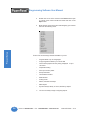
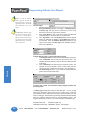
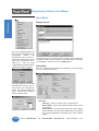
Step 1
Project Information
SELECT ACTION
Edit Program OFF-LINE
(Write to Panel Later)
➥
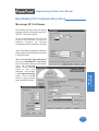
Under SELECT ACTION, click on one of the three “working mode buttons.”
If you want to work offline (not connected to a PowerPanel), click on the
button labeled Edit Program OFF-LINE (Write to Panel Later). You will
use this mode when creating a new project.
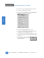
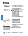
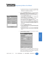
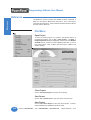
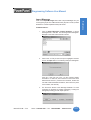
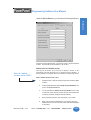
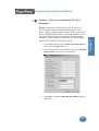
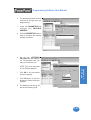
1.
From Project Information screen, click on the Edit Program
OFF-LINE (Write to Panel Later) button.
2.
Click on the Browse button if you want to navigate to another
Directory or Folder where you will store your project. If you want
to accept the default folder (where PowerPanel Programming
Software resides), just enter the name of your new project in
the empty field under Project Name.
3.
Under Start Editing Screen, leave the screen number as 1.
Click in the field next to Name to highlight New Screen. Replace
this by typing in the name of your first screen. If you haven’t
decided on a name, just leave it as is, you can change it later.
4.
Click on the DOWN arrow to the right of the Panel Type field to
view choices. Select the Panel Type you are using.
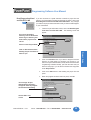
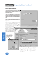
5.
Under PLC 1, click on the DOWN arrow to the right of PLC
Type and Protocol to view the list. Select the PLC Type and
Protocol you are using. Under PLC 2, select the second PLC
Type and Protocol. (If using a Touch PRLS panel, select the
TPRLS driver under PLC 2.)
PLEASE NOTE:
If you change your mind and click
on another SELECT ACTION
button, a “confirm action”
message will appear, just to make
sure that this is what you intended
to do. Click on Yes or No.
MAN-UTICW-M — V4.0
Phone: 1-563-359-7501 • Fax: 1-563-359-9094 • www.uticor.net
27
Project Setup
To have the toolbar, shown above,
appear on the righthand side of the
Main Programming Screen, click on
Edit > Toolbar > 3 Easy Steps on the
Main Menu. (You can do this after
you’ve opened a project.)
Programming Software User Manual
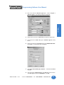
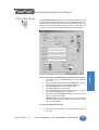
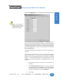
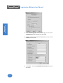
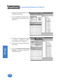
6.
Click on the View/Edit PLC COM Setup* to edit the PLC
Attributes. A dialog box will appear that is particular to the type
of PLC you have selected in the previous step. Set the attributes
to match your PLC. Click OK. Do this for both PLCs, if needed.
Project Setup
* Please note:
If using a Touch PRLS,
communication setup is
done automatically, so
you don’t need to click
on the View/Edit PLC
Com Setup button.
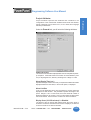
7.
You should now be back to the Project Information screen.
Check to ensure that your Ethernet/COM Port is set to match
your PC. Click on the Configuration button to make changes
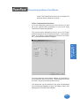
or check settings. The following dialog box will appear.
8.
Select COM1, COM2, COM3, COM4 or Ethernet. If necessary,
select Group Number (1-15) and Unit Number (1-4095). Click
on OK to accept COM port configuration and return to the
Project Information screen.
9.
Click on the OK button to accept all settings.
Click on the Ethernet/
COM Port
Configuration button
on the Project
Information Screen
or
Click on Panel > Com Configuration on
the Main Menu Bar and then click on the
Configuration button to check/change the
port settings.
You are now ready to begin configuring your first screen!
28
Phone: 1-563-359-7501 • Fax: 1-563-359-9094 • www.uticor.net
MAN-UTICW-M — V4.0
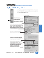
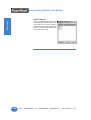
Programming Software User Manual
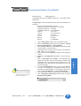
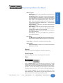
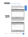
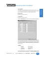
Read Program from Panel
and Edit OFF-LINE
➥
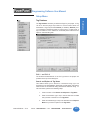
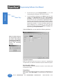
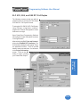
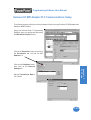
If you are connected to a panel and want to transfer a project from the
panel to your PowerPanel Programming Software for editing, click on the
Read Program from Panel and Edit OFF-LINE button. Any changes
you make to the project will not take effect until you write the edited project
to your PowerPanel.
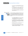
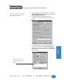
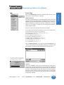
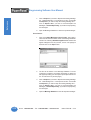
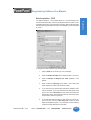
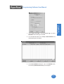
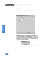
1.
From the Project Information screen, click on the Read Program
from Panel and Edit OFF-LINE. The following screen will
appear.
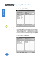
2.
Click on the Browse button if you want to navigate to another
Directory or Folder where you will store your program. If you
want to accept the default folder (usually where the PowerPanel
Programming Software resides), just enter the name that you
desire for the project you are about to Read in the empty field
under Project Name.
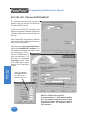
3.
Click on the Start button to start reading the project from the
panel.
4.
When the program has been read from panel, click OK.
If not using the default
directory, click on the Browse
button to go to directory and
folder where project will be
stored.
Select or enter Project Name.
The message “Project
downloaded successfully”
will appear when the program
has finished downloading.
Click on OK to exit
screen.
MAN-UTICW-M — V4.0
Phone: 1-563-359-7501 • Fax: 1-563-359-9094 • www.uticor.net
29
Project Setup
Click on Start button to Start
Reading Project from Panel or
Abort to quit.
Programming Software User Manual
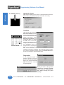
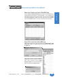
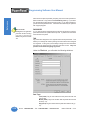
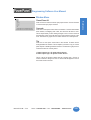
Edit Program ON-LINE
Project Setup
➥
30
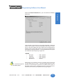
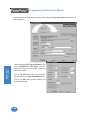
5.
You will be taken back to the Project Information Screen. Notice
that the project name entered now appears under Project Name
in this screen.
6.
Under Start Editing Screen, the Name and Number of Screen
number 1 will appear. If you want to begin editing another screen,
click on the down arrow next to Name or Number and select.
7.
Click on the OK button to begin editing. You will go to the
PowerPanel Main Programming Screen. You are now ready to
edit the selected screen.
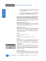
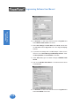
The third choice available is to make changes to the project online. Click
on the button labeled, Edit Program ON-LINE. The changes are effective
each time Save Screen or Save Project is selected, reducing downtime.
Click on Save Screen or Save Project and the changes will appear on
the panel screen immediately. This is recommended when you need to
make changes quickly to an existing user program without shutting down
the system.
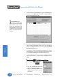
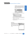
1.
From the Project Information screen, click on the button
labeled, Edit Program ON-LINE. The Panel Type, PLC Type,
and Firmware Revision of the panel will soon display.
2.
Under Start Editing Screen, screen Number 1 will appear with
that screen’s Name. If you want to begin editing a screen other
than Number 1, click on the down arrow next to the Number
field or the down arrow next to the Name field to select the
screen you want to edit.
3.
Click on OK. The screen you have selected will open on the
main programming screen for you to make changes.
4.
Click on Save Screen to download changes to the screen
immediately. Click on Save Project to transfer all changes,
including project attributes and databases. They will be
immediately downloaded to the PowerPanel.
Phone: 1-563-359-7501 • Fax: 1-563-359-9094 • www.uticor.net
MAN-UTICW-M — V4.0
Programming Software User Manual
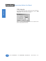
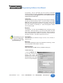
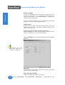
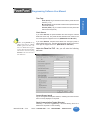
A QUICK REVIEW for “ENTER PROJECT INFORMATION”
Under ENTER PROJECT INFORMATION you will perform all or some of
the following actions (depending upon the working mode you have
selected):
Project Location will default to the directory where the
PowerPanel Software program is stored. If your project resides
in another location, click on the Browse button to navigate to a
different directory and folder.
2.
Under Project Name, click on the down arrow to view saved
projects or enter the new project name.
3.
Start Editing Screen allows you to select the screen that you
want to begin editing. To have the project open to the screen
you wish to edit, click on the down arrow to select the Name or
the Number of the screen. If it is a new project, the screen will
default to screen 1 with New Screen in the Name field. Replace
this with whatever name you wish or wait until later and rename.
4.
The next field, Panel Type, allows you to select, or change,
your PowerPanel type. Choose from the following available
types:
Click on Clear to clear your
entries and start over.
Click on Exit to quit without saving your selections,
or click on OK to save and
begin editing.
G*2 6" Mono 320 x 240, G*2 6" Color 320 x 240, G*2 8" Color
640 x 480, G*2 10" Color 640 x 480, G*2 15" Color 640 x 480,
Q*2 6" Mono 320 x 240, Q*2 6" Color 320 x 240, Q*2 8" Color
640 x 480, Q*2 8" Color TFT 640 x 480,Q*2 10" Color 640 x 480
If you are connected to the panel (editing project on-line), the
Firmware Revision of the PowerPanel’s internal software will
be displayed.
5.
MAN-UTICW-M — V4.0
Enter information for PLC1. If using a second type PLC, click in
the box in front of PLC2 and then select type for both.
Phone: 1-563-359-7501 • Fax: 1-563-359-9094 • www.uticor.net
31
Project Setup
Click on the Help Button at
anytime for help.
1.
Programming Software User Manual
Please NOTE:
PLC compatibility is always being
updated. If you don’t see your
type PLC and protocol, visit our
website @ www.UTICOR.net to
see if your PLC driver is now
available to download. If the
desired PLC driver is not
available, call technical support
at (800) 832-3647.
6.
PLC Type and Protocol allows you to further define your project
by selecting the PLC(s) used in your application and the protocol
it uses. Click on the down arrow for a list of the available PLC
types.
7.
Click on the View/Edit PLC COM Setup button to display the
PLC Attributes (for both PLC1 and PLC2, if necessary). The
attributes screen particular to the PLC and Protocol type you
have selected will appear. You may change attributes from this
screen.
8.
If you are using a Think-N-Do Map File, click on the Browse
button to go to the directory or folder where the map file resides.
The map file is simply a text delimited file that resides in any
Think-N-Do project. The PowerPanel Programming Software
is set up to pull tag names from your Think-N-Do project. This
frees the user from having to remember these tag names.
Project Setup
The map file will load into the project’s Tag Database. Tag
Database Log View will open if there are problems. You may
correct any problems from within the Think-N-Do map file or
the Tag Database.
Once you click on OK, the project will open to the screen you have selected
and you may begin creating or editing your project!
32
Phone: 1-563-359-7501 • Fax: 1-563-359-9094 • www.uticor.net
MAN-UTICW-M — V4.0
Programming Software User Manual
Step 2
Design Y
our Scr
eens
Your
Screens
Your project information has been entered and you are now ready to begin
designing your screens. Remember that you can go back to step one and
change project information, if necessary. Just click on the 1 button on the
3 Easy Steps Navigation Tool Bar, shown to the left. (This toolbar does
not display by default. To have it display on your main programming screen
as shown below, click on Edit > Toolbars > 3 Easy Steps.
For more information on the Main Programming Screen, see page
138.
Project Setup
Right click here in the
Project Screens Explorer
View window and this
menu will appear.
1.
MAN-UTICW-M — V4.0
Right click anywhere in the Project Screens Explorer View
window (shown above on the left hand side) and a popup menu
will appear. Click on New Screen (or you may click on the 2
button, Design Your Screens, on the right hand side) and the
following screen will appear.
Phone: 1-563-359-7501 • Fax: 1-563-359-9094 • www.uticor.net
33
Project Setup
Programming Software User Manual
2.
Double click on one of the screens in the Screen List to open
it, or enter a new screen number and name and click on the
Open button.
3.
Right click the mouse at any time while designing your screens
to access the following menu.
Some of the screen design features available to you are:
34
•
Program labels in up to 9 languages
•
Popup Keypad that allows you to enter data
•
Vector-based graphics for easy sizing, displayed in up to
128 colors
•
Graphical trending
•
PID loop tune face plates
•
Recipe download
•
Thumbwheel interface
•
Radio buttons
•
Analog clocks
•
Meters, switches and lamps
•
Math objects
•
Symbol Factory® library of over 3,000 factory objects
4.
You are now ready to begin configuring objects.
Phone: 1-563-359-7501 • Fax: 1-563-359-9094 • www.uticor.net
MAN-UTICW-M — V4.0
Programming Software User Manual
Step 3
Write Y
our Pr
ogram to Panel
Your
Program
Click on button for Step 3, Write Your Program to Panel. Check to ensure
that “Use PC Port” matches the port that is connected to your panel and
click on the Start button. Read the information below to learn more about
the “Write Program to Panel” screen.
Before Panel Write....
Project Information:
Provides information about the
current project you are about to
transfer to the panel.
Panel to PLC Link will display
“Not Connected” until
download is completed.
Project Setup
DON’T LOSE AN EXISTING PROGRAM! If
you’re not sure of the changes you have
made, save the existing program to a
different project name from the one you are
about to transfer to the panel before you
click on the Start button.
Press the Start Button, the program
will be transferred to the panel.
Panel Write Completed....
If the panel is connected to a PLC, the
Panel to PLC Link will display a green
dot next to the “Connected” message to
indicate that a link is established.
Panel Information will display the Total
and Free Memory in Bytes. (Most
models allow you to increase memory
by adding another RAM card.) It will
also display the Firmware Revision
number — the revision of the
PowerPanel internal firmware.
MAN-UTICW-M — V4.0
Phone: 1-563-359-7501 • Fax: 1-563-359-9094 • www.uticor.net
35
Project Setup
Programming Software User Manual
The PowerPanel is shipped with a bitmap program
installed. The image shown above will display on the
PowerPanel screen upon initial power-up. The first
project you transfer to the panel will replace this bitmap
program!
36
Phone: 1-563-359-7501 • Fax: 1-563-359-9094 • www.uticor.net
MAN-UTICW-M — V4.0
Objects
In this chapter you will be shown how to create....
— Buttons
— Indicator Buttons
— Radio Buttons
— Switches
— Step Switch
— Tri-state Switch
— Numeric Entry
— Recipe
— Thumbwheel
— Indicator Lights
— Numeric Display
— Text Objects
— Clock
— Meter
— Bar Graphs
— Line Graph
— PID Face Plate
— Change Screen
— Alarm History
— System Objects
— Multi-state Indicator
— Bitmap Objects
— Increment/Decrement Value
— Multi-function
— Report
— Data Acquisition Objects
— Control List Selector
— Screen List Selector
— Alarm List
— Touch PRLS
4
Programming Software User Manual
Objects Menu
In PLC-based control, the PLC performs the following control sequence
continuously: reads inputs, solves control logic (ladder logic), writes values,
and sets/resets outputs. The state of inputs and outputs is kept as bits in
a data table. The data table is typically organized in words, with each
word having 16 bits. Data values, such as parts count, are also kept as
words in the data table.
The PowerPanel provides direct access to the bits and words of the PLC
data table, without going through I/O modules. The panel provides this
access through its tags. The PowerPanel has tags that are mapped to
the PLC data table. The mapping between panel tags and PLC data tables
is user-defined through a simple dialog box. PowerPanel objects allow
you to set/reset bits and to read/write from the PLC data table through the
panel tags.
For example, when a panel button object is pressed, it sets a panel tag.
The panel transfers the state of this tag to the mapped bit in the PLC data
table. Similarly, the PLC may set an output bit that turns on a pilot light on
the panel.
Please Note: Panel Tags may be internal (not mapped to
the PLC) or external (mapped to the PLC).
Panel Tags may be:
Objects
•
•
•
•
•
•
•
Discrete
16-bit (Signed/Unsigned)
32-bit (Signed/Unsigned)
16-bit BCD
32-bit BCD
32-bit Floating Point
ASCII String
IMPORTANT! To learn all the steps to configuring an
object, read the instructions for the first object, Button
Object, in its entirety. It will take you through each step in
detail, explaining all the variables and choices. Because
the objects share many common features, they are not
repeated for each object. Any features that are unique to
a particular object are explained in its own section. We
recommend that you try out the tutorial, beginning on page
11, to learn the steps involved in creating a PowerPanel
project.
38
Phone: 1-563-359-7501 • Fax: 1-563-359-9094 • www.uticor.net
MAN-UTICW-M — V4.0
Programming Software User Manual
BASIC OBJECTS TOOL BAR
TEXT OBJECTS TOOL BAR
The Objects menu allows you to choose from several predefined objects.
Objects provide generic panel functions. The objects can be accessed
from the Object Tool Bars — Basic Objects, Text Objects, System
Objects, Bitmap Objects, and Data Acquisition Objects — shown above
and to the left, and the Objects Menu shown on the preceding page.
SYSTEM OBJECTS TOOL BAR
All of the objects in this menu have user-defined frame types, line and fill
colors, and text. To configure an object, click on the object icon on the
object tool bar or on the object name in the menu drop down list with your
mouse.
Basic Objects Tool Bar Icons
BITMAP OBJECTS TOOL BAR
DATA Acquisition OBJECTS
TOOL BAR
MAN-UTICW-M — V4.0
Multi-function
Indicator Button
•
Report
Radio Button
•
Increment/Decrement
Value
•
Control List Selector
•
Screen List Selector
•
Alarm List
•
Touch PRLS
Button
•
Switches
•
Step Switch
•
Tri-State Switch
•
•
•
•
•
•
•
•
•
•
•
•
•
•
Numeric Entry
•
Multi-state Indicator
Recipe
Thumbwheel
Objects
Configure an object by
selecting it from the
OBJECT MENU or
OBJECT TOOL BARS
•
•
•
•
Indicator Light
Numeric Display
Analog Clock
Digital Clock
Meter
Bar Graph
Line Graph
PID Face Plate
Dynamic Bitmap
Change Screen
Alarm History
Phone: 1-563-359-7501 • Fax: 1-563-359-9094 • www.uticor.net
39
Programming Software User Manual
Text Objects Tool Bar Icons
•
•
•
Static Text
•
Dynamic Text
•
Text Entry
Triggered Text
Lookup Text
System Objects Tool Bar Icons
•
Adjust Contrast
•
Increment/Decrement
Hour
•
Activate Screen Saver
•
Select Language
Bitmap Objects Tool Bar Icons
•
•
Dynamic Bitmap
•
Multi-state Bitmap
Bitmap Button
Objects
Data Acquisition Tool Bar Icons
40
•
Table View
•
Frequency Chart
•
Statistics
Phone: 1-563-359-7501 • Fax: 1-563-359-9094 • www.uticor.net
MAN-UTICW-M — V4.0
Programming Software User Manual
Button Object
Pressing a Button object allows you to WRITE to a Tag. It can be
displayed in a variety of colors, sizes and shapes and has a simulation
option (allowing you to see how it will look when pressed). You may
select from 5 types of button states: Momentary ON, Momentary OFF,
Set ON, Set OFF and TOGGLE.
Choose from 128 Colors!
MAN-UTICW-M — V4.0
To Choose a Button Style, perform the following steps:
1. Under Select Style, click on the style you prefer for the button
object you are creating.
2. Your choice will appear under Selected Style.
Phone: 1-563-359-7501 • Fax: 1-563-359-9094 • www.uticor.net
41
Objects
Click on the down arrow next to
the default color block for text or
background to view the color
palette. Move the cursor over your
choice and simply click to select.
To put a Label on a Button, perform the following steps:
1. Click on the box in front of Label Text.
2. Use the UP/DOWN arrows after the Language box to select a
language number. (See section on Language, page 221.)
3. Select Character Size from the available choices.
4. Enter Label Text up to 40 characters.
5. Select the Position of the label, whether you want it to appear
at the Top or the Bottom of the object frame.
6. Select the Text and Background Color. Click on the down
arrow to view the color palette.
7. Display Frame is selected by default. If you do not want the
frame around the button to be visible, click on the box to deselect
(the box will be empty).
Programming Software User Manual
Enter a Tag Name:
1. Enter a Tag Name or click on the down arrow and select the
Tag Name that you want the button to correspond to.
2. If the Tag Name is new, the Add New Tag Details dialog box
will appear where you will map the tag. The Tag Name will
appear in the first field. Enter an Address String appropriate
for your type PLC. Click on the OK button.
NOTE: To edit the Address String, with your cursor in the
Tag Name field, click on the right mouse button. The Edit
Tag Details screen will appear.
For more information about Tags, see
Tag Database, page 190.
PLEASE NOTE: If your panel is
connected to multiple PLCs, use
the Station Number to address a
specific PLC. For example: 2–
V2002 would address the PLC
Station Number 2.
PLEASE NOTE: If you select
Momentary ON or Momentary
OFF, the PLC must set bit to
proper state on powerup. This
must be done when programming
PLC Logic.
Select from the following Actuator Types:
Actuator Type determines how the tag will be controlled. NOTE: If you
have assigned Password Protection for this object and select
Momentary On or Momentary Off, the protection feature is disabled
with this actuator type.
•
•
•
•
•
Enter On/Off Text:
Here you will enter the Text that will appear within the object, and
control how that text will appear.
Objects
1.
2.
Hello...
Hola...
Guten Tag...
For each object, you may program
the text to display in up to 9
Languages! (See Language section
on page 221.)
Momentary On will turn the tag on for as long as you touch
the button. (Password Protection is disabled.)
Momentary Off will turn the tag off for as long as you touch
the button. (Password Protection is disabled.)
Set On will latch the tag ON.
Set Off will latch the tag OFF.
Toggle will change the state of the tag every time the button
is pressed.
3.
4.
5.
Select the Language number (1–9) for the On/Off Text.
Type in what you want to appear within the button for the On
Text and for the Off Text (i.e., you might want to place the words
STOP and RUN inside the buttons, instead of Off and On).
Select Character Size from the available choices
Select the Color of the Text and the Color of the Background.
If you want the Text or the Background to Blink, click on the
box below Blink to place a check mark indicating that the option
is enabled.
OK/Cancel/Help Buttons
•
Click on OK button to save your selections and exit the dialog
box.
•
Click on Cancel button to exit the dialog box without saving
your selections.
•
Click on Help button to go to the Help Topic for that dialog
box.
Place Button on the screen and size it.
•
To size the button, grab a handle and drag it to the size you
want.
42
Phone: 1-563-359-7501 • Fax: 1-563-359-9094 • www.uticor.net
MAN-UTICW-M — V4.0
Programming Software User Manual
•
Grab a handle with
your mouse
To move the button, select it, click and hold left mouse button
and drag it to the area of the screen where you want it to
appear.
Simulate Press
To Simulate Press, double click the object to bring up the object dialog
box. You may also click on the object(s) on the screen that you want to
simulate and then click on the arrows in the standard tool bar to
simulate previous state or simulate next state. (You may have to drag
the dialog box to see the object on the programming screen.) Click on
the Simulate Press button to see how the button object will display on
the screen when pressed or when it switches between states.
Protection Tab
Click on the Protection Tab
IMPORTANT!
Password Protection is not
intended to work with objects
when the actuator type selected is
Momentary On and Momentary
Off.
MAN-UTICW-M — V4.0
Objects
The following touch objects allow you
to enable protection and assign
passwords to allow a group or individual
(user-defined) to have access to that
object:
Buttons
Indicator Buttons
Switches
Step Switches
Tri-State Switches
Numeric Entry
Recipe
Thumbwheel
Text Entry
Change Screen
Alarm History
Increment/Decrement Hour
Activate Screen Saver
Adjust Contrast
Select Language
Bitmap Button
Increment/Decrement Value
Multi-function
Report
Screen List Selector
Control List Selector
Alarm List
The Password Protect Object feature allows you to prevent unauthorized users from accessing certain objects and their functions. With
Protection enabled, when the operator presses the object on the panel
screen, a keypad will appear prompting the operator to enter the
password. This feature is useful when several people will be using the
PowerPanel to perform different tasks, such as, changing initial values,
or monitoring system status. To enable password protection for the
object, click in the box in front of the groups you wish to allow access.
Edit Passwords
There are eight groups that you may assign Names and Passwords to.
Passwords allow you to implement restrictions on who can use the
password protected objects (e.g., to make system or internal panel
adjustments, enter text or values, or control a machine function in your
application). Click on the Edit Passwords button to setup or change
the passwords.
Phone: 1-563-359-7501 • Fax: 1-563-359-9094 • www.uticor.net
43
Programming Software User Manual
GROUP
(You may change the Group names to suit your application.)
The Group names that
you enter here
will then appear in the
Protection tab dialog
boxes of all applicable
objects.
✔
✔
✔
✔
✔
✔
✔
✔
Managers
Engineers
Supervisors
Maintenance
Shift 1 Operator
Shift 2 Operator
Shift 3 Operator
General
Click in the box in front of
the group to allow access
by that group to the
object.
Objects
Please NOTE: If you enter a
password with leading zeroes, e.g.,
00003 or 00533, the leading
zeroes will be ignored!
A keypad similar to the one shown
below will appear on the panel
when a protected object is pressed,
prompting the operator to enter the
password.
Password/Tag
Select whether or not you want your password to be stored in the
PowerPanel or in the PLC. If you choose Password, it will be stored in
the panel. If you choose Tag, it will be stored in the PLC.
PASSWORD
A 1–10 digit number (numeric only) is assigned here that the user must
enter to perform protected functions for a particular Group. You will not be
allowed to enter a password if you select Tag in the second column.
Do not enter leading zeroes in a password. Leading zeroes are
ignored. In other words, if you enter a password of 00456, your
password will be 456.
TAG
Tag names are assigned to PLC addresses that hold the passwords. This
allows you to store the codes in your PLC. You will not be allowed to
enter a Tag if you select Password in the second column.
44
Phone: 1-563-359-7501 • Fax: 1-563-359-9094 • www.uticor.net
MAN-UTICW-M — V4.0
Programming Software User Manual
Visibility/Details Tab
Click on the Visibility/Details Tab
Details
1.
2.
MAN-UTICW-M — V4.0
Type in a name for the object in the space provided under Object
Name. The name can be up to 40 characters long.
Type in a description of the object in the space provided under
Object Description. An Object Description can be up to 400
characters long.
Phone: 1-563-359-7501 • Fax: 1-563-359-9094 • www.uticor.net
45
Objects
Visibility
1. Check the box in front of Visibility Tag if you want to control
when the object is visible on the screen. (If it is not checked
the object will always be visible.)
2. Click on the down arrow next to the Tag Name box to view a list
of the tags you have previously programmed or create a new
one. Select the tag that links the object to the register bit that
you want to control it.
3. Select whether you want the Object Visible when the bit is ON
or OFF.
Programming Software User Manual
Indicator Button Object
An Indicator Button combines a regular button with an indicator light.
It allows you to perform a WRITE operation to one bit and a READ
operation from a second discrete location. The state of that READ
location determines whether the button is displayed in the ON or OFF
mode. You may choose to make the READ and WRITE location the
same.
Objects
To put a Label on an Indicator Button, perform the following steps:
1. Click on the box in front of Label Text.
2. Use the UP/DOWN arrows after the Language box to select a
language number. (See section on Language, page 221.)
3. Select Character Size from the available choices.
4. Enter Label Text up to 40 characters.
5. Select the Position of the label, whether you want it to appear
at the Top or the Bottom of the object frame.
6. Select the Text and Background Color. Click on the down
arrow to view the color palette.
7. Display Frame is selected by default. If you do not want the
frame around the button to be visible, click on the box to deselect
(the box will be empty).
NOTE: To edit the Address
String, with your cursor in the
Tag Name field, click on the
right mouse button. The Edit
Tag Details screen will appear.
46
To Choose an Indicator Button Style, perform the following steps:
1. Under Select Style, click on the style you prefer for the button
object you are creating.
2. Your choice will appear under Selected Style.
Enter a Tag Name:
1. Enter a Tag Name or click on the down arrow and select the
Tag Name that you want the Indicator button and the Indicator
to correspond to.
2. If the Tag Name is new, the Add New Tag Details dialog box
will appear where you will enter tag details. The Tag Name will
Phone: 1-563-359-7501 • Fax: 1-563-359-9094 • www.uticor.net
MAN-UTICW-M — V4.0
Programming Software User Manual
appear in the first field. Enter an Address String appropriate
for your type PLC. Click on the OK button.
PLEASE NOTE: If you have
assigned Password Protection for
this object and select Momentary
On or Momentary Off, the
protection feature will not be
enabled.
Also, if you select Momentary ON
or Momentary OFF, the PLC must
set bit to proper state on powerup.
This must be done when
programming PLC Logic.
Select from the following Actuator Types: Actuator Type determines
how the tag will be controlled.
•
Momentary On will turn the tag on for as long as you touch
the button. (Password Protection is disabled.)
•
Momentary Off will turn the tag off for as long as you touch
the button. (Password Protection is disabled.)
•
Set On will latch the tag ON.
•
Set Off will latch the tag OFF.
•
Toggle will change the state of the tag every time the button
is pressed.
Enter On/Off Text:
Here you will enter the Text that will appear within the object, and
control how that text will appear.
1. Select the Language number (1–9) for the On/Off Text.
2. Type in what you want to appear within the button for the On
Text and for the Off Text (i.e., you might want to place the words
STOP and RUN inside the buttons, instead of Off and On).
3. Select Character Size from the available choices
4. Select the Color of the Text and the Color of the Background.
5. If you want the Text or the Background to Blink, click on the
box below Blink to place a check mark indicating that the option
is enabled.
Protection (See Button Object.)
Visibility/Details (See Button Object.)
Place Indicator Button on the screen and size it.
•
To size the Indicator button, select it, grab a handle and drag.
•
To move the button, select it, click and hold left mouse button
and drag it to where you want it to appear on the screen.
Simulate Press
To Simulate Press, double click the object to bring up the object dialog
box. You may also click on the object(s) on the screen that you want to
simulate and then click on the arrows in the standard tool bar to
simulate previous state or simulate next state. (You may have to drag
the dialog box to see the object on the programming screen.) Click on
the Simulate Press button to see how the button object will display on
the screen when pressed or when it switches between states.
MAN-UTICW-M — V4.0
Phone: 1-563-359-7501 • Fax: 1-563-359-9094 • www.uticor.net
47
Objects
OK/Cancel/Help Buttons
•
Click on OK button to save your selections and exit the dialog
box.
•
Click on Cancel button to exit the dialog box without saving
your selections.
•
Click on Help button to go to the Help Topic for that dialog
box.
Programming Software User Manual
Radio Buttons
The Radio Button object has a maximum of 8 buttons, however, only
one can be ON at any given time. When a button is pressed it releases
any button that may be ON, and becomes the active button. Each
button controls a bit and is assigned an area of the touchscreen. Radio
buttons can have from 2 to 8 buttons. (Please note that no more that 6
vertical buttons can be used for 6-inch panels.)
Objects
To put a Label on a Radio Button, perform the following steps:
1. Click on the box in front of Label Text.
2. Use the UP/DOWN arrows after the Language box to select a
language number. (See section on Language, page 221.)
3. Select Character Size from the available choices.
4. Enter Label Text up to 40 characters.
5. Select the Position of the label, whether you want it to appear
at the Top or the Bottom of the object frame.
6. Select the Text and Background Color. Click on the down
arrow to view the color palette.
7. Display Frame is selected by default. If you do not want the
frame around the button to be visible, click on the box to deselect
(the box will be empty).
To Choose a Radio Button Style, perform the following steps:
1. Under Select Style, click on the style you prefer for the button
object you are creating.
2. Your choice will appear under Selected Style.
NOTE: To edit the Address
String, with your cursor in the
Tag Name field, click on the
right mouse button. The EDIT
TAG DETAILS screen will
appear.
48
Enter a Tag Name:
1. Enter a Tag Name or click on the down arrow and select the
Tag Name that you want to button to correspond to.
2. If the Tag Name is new, the Add New Tag Details dialog box
will appear where you will enter tag details. The Tag Name will
appear in the first field. Enter an Address String appropriate
for your type PLC. Click on the OK button.
Phone: 1-563-359-7501 • Fax: 1-563-359-9094 • www.uticor.net
MAN-UTICW-M — V4.0
Programming Software User Manual
Please Note: This object can use a signed or unsigned Data Type.
Button 1 = Bit 0 in assigned tag. Button 8 = Bit 7 in assigned tag.
Bit 9 to 15, not used.
Select Number of Buttons:
1. Click on the UP or DOWN arrow to select the number of radio
buttons. You may choose from 2 to 8 buttons. (You may only
have 6 buttons for 6-inch panels.)
Enter On/Off Text:
Text size and color are programmed under the General Tab. These
characteristics will be implemented for all of the inside button text.
1. Select the Character Size for the On Text and the Off Text.
2. Choose the Color of the Text by clicking on the arrow button
to view the color palette. Move the cursor over the color you
want and click to select.
3. Select whether or not the Text will Blink.
4. Next, select the Background Color of the button and whether
or not it will Blink.
5. Each Radio Button (from 2 to 8) may contain different text and
a different language. Click on the Button #1 tab.
Click on the Button #1 Tab to
edit Language and On/Off Text.
Objects
6.
Choose the Language number (1–9) and type in the text as
you want it to appear within that button when ON and when
OFF (i.e., you might want to place the words STOP and RUN
inside the buttons, instead of Off and On).
Remember that the other universal characteristics for the
button text and background have been chosen under the
General Tab (character size, color, etc.).
MAN-UTICW-M — V4.0
Phone: 1-563-359-7501 • Fax: 1-563-359-9094 • www.uticor.net
49
Programming Software User Manual
Protection (See Button Object.)
Visibility/Details (See Button Object.)
OK/Cancel/Help Buttons
•
Click on OK button to save your selections and exit the dialog
box.
•
Click on Cancel button to exit the dialog box without saving
your selections.
•
Click on Help button to go to the Help Topic for that dialog
box.
Place Radio Button on the screen and size it.
•
To size the button, select it, grab a handle and drag.
•
To move the button, select it, click and hold left mouse button
and drag to where you want it to appear on the screen.
Objects
Simulate Press
To Simulate Press, double click the object to bring up the object dialog
box. You may also click on the object(s) on the screen that you want to
simulate and then click on the arrows in the standard tool bar to
simulate previous state or simulate next state. (You may have to drag
the dialog box to see the object on the programming screen.) Click on
the Simulate Press button to see how the button object will display on
the screen when pressed or when it switches between states.
50
Phone: 1-563-359-7501 • Fax: 1-563-359-9094 • www.uticor.net
MAN-UTICW-M — V4.0
Programming Software User Manual
Switch Object
There are several types of Switch objects that you may place on the
PowerPanel screen. They simulate mechanical switches of the same
type, e.g.; Throw Switch, Selector Switch, Slide Switch, Toggle Switch,
etc.
To Choose a Switch Style, perform the following steps:
1. Under Select Style, click on the style you prefer for the switch
object you are creating.
2. Your choice will appear under Selected Style.
NOTE: To edit the Address
String, with your cursor in the
Tag Name field, click on the
right mouse button. The EDIT
TAG DETAILS screen will
appear.
MAN-UTICW-M — V4.0
Enter a Tag Name:
1. Enter a Tag Name or click on the down arrow and select the
Tag Name that you want the switch to correspond to.
2. If the Tag Name is new, the Add New Tag Details dialog box
will appear where you will enter tag details. The Tag Name will
appear in the first field. Enter an Address String appropriate
for your type PLC. Click on the OK button.
Phone: 1-563-359-7501 • Fax: 1-563-359-9094 • www.uticor.net
51
Objects
To put a Label on a Switch, perform the following steps:
1. Click on the box in front of Label Text.
2. Use the UP/DOWN arrows after the Language box to select a
language number. (See section on Language, page 221.)
3. Select Character Size from the available choices.
4. Enter Label Text up to 40 characters.
5. Select the Position of the label, whether you want it to appear
at the Top or the Bottom of the object frame.
6. Select the Text and Background Color. Click on the down
arrow to view the color palette.
7. Display Frame is selected by default. If you do not want the
frame around the button to be visible, click on the box to deselect
(the box will be empty).
Programming Software User Manual
Select the Switch Background color by clicking on the DOWN arrow and
selecting a color from the palette.
PLEASE NOTE: If you select
Momentary ON or Momentary
OFF, the PLC must set bit to
proper state on powerup. This
must be done when programming
PLC Logic.
Select from the following Actuator Types:
Actuator Type determines how the tag will be controlled. If you have
assigned Password Protection for this object and select Momentary On or Momentary Off, the protection feature will not be
enabled with this actuator type.
•
Momentary On will turn the tag on for as long as you touch
the switch. (Password Protection is disabled.)
•
Momentary Off will turn the tag off for as long as you touch
the switch. (Password Protection is disabled.)
•
Set On will latch the tag ON.
•
Set Off will latch the tag OFF.
•
Toggle will change the state of the tag every time the switch
is pressed.
Enter On/Off Text:
Here you will enter the Text that will appear within the object, and
control how that text will appear.
1. Select the Language number (1–9) for the On/Off Text.
2. Type in what you want to appear within the switch for the On
Text and for the Off Text (i.e., you might want to place the words
STOP and RUN inside the switches, instead of Off and On).
3. Select Character Size from the available choices
4. Select the Color of the On Text and the Color of the Off Text.
5. If you want the Text to Blink, click on the box below Blink to
place a check mark indicating that the option is enabled.
Objects
Protection (See Button Object.)
Visibility/Details (See Button Object.)
OK/Cancel/Help Buttons
•
Click on OK button to save your selections and exit the dialog
box.
•
Click on Cancel button to exit the dialog box without saving
your selections.
•
Click on Help button to go to the Help Topic for that dialog
box.
Place Switch on the screen and size it.
•
To size a switch, click on it to select, grab a handle with the
mouse and drag to the size you want.
•
To move the switch, select it, click and hold left mouse button,
and drag to where you want it to appear on the screen.
52
Phone: 1-563-359-7501 • Fax: 1-563-359-9094 • www.uticor.net
MAN-UTICW-M — V4.0
Programming Software User Manual
Step Switch Object
The Step Switch object simulates a Mechanical Step Switch on the
PowerPanel. It allows you to simultaneously monitor and control two,
three, or four different bits and display ON and OFF text for each bit. Each
time the Step Switch is pressed, each bit will be cycled one at a time from
OFF to ON with only one bit ON at a time.
To Choose a Step Switch Style, perform the following steps:
1. Under Select Style, click on the style you prefer for the button
object you are creating.
2. Your choice will appear under Selected Style.
Choose the Number of Steps (from 1 to 4) in the process or application
that you want your switch to control. Enter the number of steps or click on
the up/down arrows to select.
MAN-UTICW-M — V4.0
Phone: 1-563-359-7501 • Fax: 1-563-359-9094 • www.uticor.net
53
Objects
To put a Label on a Switch, perform the following steps:
1. Click on the box in front of Label Text.
2. Use the UP/DOWN arrows after the Language box to select a
language number. (See section on Language, page 221.)
3. Select Character Size from the available choices.
4. Enter Label Text up to 40 characters.
5. Select the Position of the label, whether you want it to appear
at the Top or the Bottom of the object frame.
6. Select the Text and Background Color. Click on the down
arrow to view the color palette.
7. Display Frame is selected by default. If you do not want the
frame around the button to be visible, click on the box to deselect
(the box will be empty).
Programming Software User Manual
Step #1 Tab
NOTE: To edit the Address
String, with your cursor in the
Tag Name field, click on the
right mouse button. The EDIT
TAG DETAILS screen will
appear.
1.
2.
3.
4.
5.
Click on Step #1 tab.
Enter Tag Name for Step #1.
Select Language (1 to 9) for On/Off Text and then enter the
On Text and Off Text that you want to appear within Step Switch
#1.
Select Character Size, Color of Text and Background and
whether or not, Text and/or Background will Blink.
Repeat for Step #2, Step #3 and Step #4, if necessary.
Protection (See Button Object.)
Objects
Visibility/Details (See Button Object.)
OK/Cancel/Help Buttons
•
Click on OK button to save your selections and exit the dialog
box.
•
Click on Cancel button to exit the dialog box without saving
your selections.
•
Click on Help button to go to the Help Topic for that dialog
box.
Place Step Switch on the screen and size it.
•
To size the switch, grab a handle and drag.
•
To move the switch, select it, click and hold left mouse button
and drag.
Simulate Press
To Simulate Press, double click the object to bring up the object dialog
box or click on the object to highlight and thenclick on the arrows in the
standard tool bar to simulate previous state or simulate next state.
Select the tab of the Step you want to simulate (if on General tab, will
simulate Step 1 only). Click on the Simulate Press button to see how
the switch object will display on the screen when pressed
54
Phone: 1-563-359-7501 • Fax: 1-563-359-9094 • www.uticor.net
MAN-UTICW-M — V4.0
Programming Software User Manual
Tri-State Switch Object
The Tri-State Switch object controls two bits at a time from two different
tags. It consists of three buttons. If the first button is pressed, both the
bits are OFF. If the second button is pressed, the first bit is ON and second
bit is OFF. If third button is pressed, the first bit is OFF and second bit is
ON.
NOTE: To edit the Address
String, with your cursor in the
Tag Name field, click on the
right mouse button. The EDIT
TAG DETAILS screen will
appear.
MAN-UTICW-M — V4.0
To put a Label on a Switch, perform the following steps:
1. Click on the box in front of Label Text.
2. Use the UP/DOWN arrows after the Language box to select a
language number. (See section on Language, page 221.)
3. Select Character Size from the available choices.
4. Enter Label Text up to 40 characters.
5. Select the Position of the label, whether you want it to appear
at the Top or the Bottom of the object frame.
6. Select the Text and Background Color. Click on the down
arrow to view the color palette.
7. Display Frame is selected by default. If you do not want the
frame around the button to be visible, click on the box to deselect
(the box will be empty).
To Choose a Tri-State Switch Style, perform the following steps:
1. Under Select Style, click on the style you prefer for the button
object you are creating.
2. Your choice will appear under Selected Style.
Tag Names
Click on the down arrow to select or enter new Tag Names for the First
Bit and for the Second Bit. If the Tag Name is new, the Add New Tag
Details dialog box will appear where you will enter tag details. The Tag
Phone: 1-563-359-7501 • Fax: 1-563-359-9094 • www.uticor.net
55
Objects
PLEASE NOTE:
The Tri-State switch object is
always snapped to a touch cell to
ensure that it operates properly
on the panel screen. If you select
the vertical style, you will notice
that a label is not available
(grayed out).
Programming Software User Manual
Name will appear in the first field. Enter an Address String appropriate
for your type PLC. Click on the OK button.
Text
Here you will enter the Text that will appear within the object, and control
how that text will appear.
1.
2.
3.
4.
Select the Language number for the Off, First (bit) and Second
(bit) Text.
Type in what you want to appear within the button for the Off
Text, First Text and for the Second Text.
Select Character Size from the available choices.
Select the Color of the Text and the Color of the Background.
If you want the Text or the Background to Blink, click on the box
below Blink to place a check mark indicating that the option is
enabled.
Protection (see Button Object.)
Visibility/Details (see Button Object.)
Objects
OK/Cancel/Help Buttons
•
Click on OK button to save your selections and exit the dialog
box.
•
Click on Cancel button to exit the dialog box without saving
your selections.
•
Click on Help button to go to the Help Topic for that dialog
box.
Place Tri-State Switch on the screen and size it.
•
To size the switch, grab a handle and drag it to size you want.
•
To move the switch, select it, click and hold left mouse button
and drag to where you want it to appear on the screen.
56
Phone: 1-563-359-7501 • Fax: 1-563-359-9094 • www.uticor.net
MAN-UTICW-M — V4.0
Programming Software User Manual
Numeric Entry Object
The Numeric Entry object allows you to write a value to a PLC register. A
numeric keypad will pop up when the Numeric Entry object is pressed on
the PowerPanel screen. When you select a Tag Name, you will be selecting
the PLC location where you want the keypad accumulator data to go. In
other words, the value the operator enters on the keypad will be written to
the PLC location.
Please Note: Numeric
label is truncated to 20
characters on the popup
keypad.
MAN-UTICW-M — V4.0
Phone: 1-563-359-7501 • Fax: 1-563-359-9094 • www.uticor.net
57
Objects
To put a Label on the Numeric Entry object, perform the following
steps:
1. Click on the box in front of Label Text.
2. Use the UP/DOWN arrows after the Language box to select a
language number. (See section on Language, page 221.)
3. Select Character Size from the available choices.
4. Enter Label Text up to 40 characters.
5. Select the Position of the label, whether you want it to appear
at the Top or the Bottom of the object frame.
6. Select the Text and Background Color. Click on the down
arrow to view the color palette.
7. Display Frame is selected by default. If you do not want the
frame around the object to be visible, click on the box to deselect
(the box will be empty).
Programming Software User Manual
NOTE: To edit the Address
String, with your cursor in the
Tag Name field, click on the
right mouse button. The EDIT
TAG DETAILS screen will
appear.
PLEASE NOTE: When a single
tag is used, the I/O type the tag
can accept is Read/Write.
When two tags are used, the first
tag’s I/O type also accepts Read
Only and, therefore, can define
source expressions.
Choose Tag(s):
1. Choose whether or not you want to use a single tag for both
Entry and Display purposes, or two tags — a Display Tag and
an Entry Tag. Two tags will be necessary if you are using
Expressions in the tag. (See Note to the left.)
2. Enter a Tag Name or click on the down arrow and select the
Tag Name that you want the object to correspond to.
3. If the Tag Name is new, the Tag Entry dialog box will appear
where you will enter tag details. The Tag Name will appear in
the first field. Enter an Address String appropriate for your
type PLC and select the Data Type (from available choices).
Click on the OK button.
Objects
To Enter Range Check , perform the following steps:
1. Under Range Check, set the minimum and maximum set points.
Click on Minimum, the low end point, and enter a value. The
operator will not be allowed to enter a value lower than the value
in this field.
2. Click on Maximum, the high end point, and enter a value. The
operator will not be allowed to enter a value higher than the
value in this field. (Valid Range is shown in the next window.)
3. The Valid Range is shown. Your minimum and maximum set
points must be within these limits.
To Select the Format of the Numeric Entry Keypad, perform the
following steps:
The Data Type is dependent upon the Tag data type. In turn, the Tag
data type is dependent upon the type of PLC you are using. Therefore,
your selections next to Data Type in this object will be limited by your Tag
and PLC data type. PowerPanel Programming Software will automatically
limit your selections based on the PLC and Tag address format. The
program will also let you know if you have entered an invalid data type.
SIGNED DATA TAG:
SIGNED Keypad only
UNSIGNED DATA TAG: UNSIGNED, OCTAL, HEX Keypad
58
Phone: 1-563-359-7501 • Fax: 1-563-359-9094 • www.uticor.net
MAN-UTICW-M — V4.0
Programming Software User Manual
BCD DATA TAG:
BCD Keypad only
FLOATING POINT TAG (if available for that PLC): FLOATING POINT
Keypad only
The Data Types, and their respective ranges, that may be available, are
as follows:
Signed 16 Decimal:-32768 to +32767
Signed 32 Decimal:-2147483648 to +2147483647
Unsigned 16 Decimal: 0 to 65535
Unsigned 32 Decimal: 0 to 4294967295
Octal 16:
0 to 177777
Octal 32:
0 to 37777777777
Hex 16:
0 to FFFF
Hex 32:
0 to FFFFFFFF
BCD 16:
0 to 9999
BCD 32:
0 to 99999999
1.
2.
3.
4.
5.
6.
7.
NOTE: If a Decimal Point tag
is selected, the Fractional Digits
will not be used. The number
of fractional digits will come
from the value of the tag.
MAN-UTICW-M — V4.0
9.
Phone: 1-563-359-7501 • Fax: 1-563-359-9094 • www.uticor.net
59
Objects
8.
Click on Data Type and select from the available choices.
Click on Justification and select from the following: Leading
Zeroes, Leading Spaces, or Trailing Spaces.
Click on Size and select from the available character sizes. (Click
on down arrow to view list of sizes.)
Under Color, click on down arrow to view the color palette for
Text. Click on any color to select.
Click on the box in front of Blink if you want your text characters
to blink.
Select color for Background and whether or not you want it to
Blink.
Click on Total Digits under # Digits. The PowerPanel will
display the minimum value and the maximum number inside
the keypad. Here you will select how many digits, from 1 to 10
(depending on the data type and tag value type chosen), that
you want to display.
If you want Fractional Digits, enter 1 through 10 here (select 0
for none). For example, if your maximum value is 999, you
would enter 3 under total digits. If your maximum value is 99.9,
enter 3 under Total Digits and 1 under Fractional Digits.
If you want a tag to control the decimal points, click in the box in
front of Use tag for decimal point and then enter or select a
Decimal point Tag Name.
Programming Software User Manual
Scaling Tab
Click on the Scaling tab if you
want the Display Value to be
different than the PLC Value.
Objects
Under the Numeric Entry object Scaling tab, you can scale the entered
value from the numeric entry object to another value in the PLC. Enter
the Point 1 and Point 2 PLC Values and Point 1 and Point 2 Display
Values. (An example of SCALING is provided on the dialog box,
above.)
This is an example of a SIGNED
DECIMAL Popup Keypad as it will
display on your PowerPanel Screen.
If you enter an invalid value, press the
Clear (CLR) button and reenter.
➥
60
Phone: 1-563-359-7501 • Fax: 1-563-359-9094 • www.uticor.net
MAN-UTICW-M — V4.0
Programming Software User Manual
Notification and Handshake Tab:
Click on this tab if you want to configure a discrete tag that will notifiy the
panel when the numeric entry has been received. To let the operator
know, the keypad will automatically close when the value has been
received.
Click in the box in front of Use Notification and Handshake
tags to enable this option.
2.
In the Notification Tag Name field, enter or select a tag name
where the tag will notify a location that a numeric entry value
has been received.
3.
In the Handshake Tag Name field, enter or select a tag name
where the tag will return a value to the panel that will close the
keypad thereby letting the operator know that the value was
received and entered.
4.
Enter a Handshake Time out time in milliseconds. Enter a
number between 1 and 65535.
Protection (see Button Object.)
Visibility/Details (see Button Object.)
OK/Cancel/Help Buttons
•
Click on OK button to save your selections and exit the dialog
box.
•
Click on Cancel button to exit the dialog box without saving
your selections.
•
Click on Help button to go to the Help Topic for that dialog
box.
Place Object on the screen and size it.
•
To size the Numeric Entry object, grab a handle and drag.
•
To move the object, select it, click and hold left mouse button
and drag to where you want it to appear on the screen.
MAN-UTICW-M — V4.0
Phone: 1-563-359-7501 • Fax: 1-563-359-9094 • www.uticor.net
61
Objects
1.
Programming Software User Manual
Recipe Object
The Recipe object allows you to write preset values of up to 20 Tags to the
PLC to change the process. Thus, this feature can be used to download
"recipes" to the PLC.
Objects
Important Note: If you are using a
Recipe object that was created in
an older version of PowerPanel
Programming Software (1.x), this
version (V3.0) will recognize it and
convert the old Recipe object to the
new Recipe object. This is true
whether you are reading from the
panel or from the project file.
Ensure that you have the latest
version of the firmware.
Important Note: If overlapping this
object, the maximum number of tags
that can be written to is 40.
To put a Label on the Recipe object button, perform the following
steps:
1. Click on the box in front of Label Text.
2. Use the UP/DOWN arrows after the Language box to select a
language number. (See section on Language, page 221.)
3. Select Character Size from the available choices.
4. Enter Label Text up to 40 characters.
5. Select the Position of the label, whether you want it to appear
at the Top or the Bottom of the object frame.
6. Select the Text and Background Color. Click on the down arrow
to view the color palette.
7. Display Frame is selected by default. If you do not want the
frame around the object to be visible, click on the box to deselect
(the box will be empty).
Enter Text:
Here you will enter the Text that will appear within the object, and control
how that text will appear.
1.
2.
3.
4.
5.
62
Select the Language number (1–9) for the Text.
Type in what you want to appear within the button.
Select Character Size from the available choices
Select the Color of the Text and the Color of the Background.
If you want the Text or the Background to Blink, click on the
box below Blink to place a check mark indicating that the option
is enabled.
Phone: 1-563-359-7501 • Fax: 1-563-359-9094 • www.uticor.net
MAN-UTICW-M — V4.0
Programming Software User Manual
Enter Tag Name and Register Values:
Pressing the Recipe button allows you to write values to several locations
at once. The screen shown above is where you will enter the values to be
written to the PLC location.
Click on the Add/Edit Tags button. The following window will
appear.
2.
Under Destination, Tag Name, click on the down arrow to view
list of available tags (or enter a new name). Select the tag you
wish to use. If you enter a new tag name the Add New Tag
Details dialog will open. Enter the tag details.
The Destination tag type determines the data format.
Under Source, choose Constant (default) or Another tag for
the value.
If you choose Constant, the Value from a constant group will
be enabled and Value from another tag will be disabled.
Enter a Value that you want written to the register.
Objects
1.
3.
4.
5.
6.
MAN-UTICW-M — V4.0
Phone: 1-563-359-7501 • Fax: 1-563-359-9094 • www.uticor.net
63
Programming Software User Manual
7.
Select from the available Data Format choices (i.e., Unsigned
Decimal, Signed Decimal, Octal or Hex.)
8. If you choose Another tag, the Value from another tag will be
enabled and Value from a constant will be disabled.
9. Enter a new source tag or choose an existing tag from those
available. Only the tags that are of the same data type as the
destination tag will be displayed.
10. Repeat for the second entry. You may continue writing values
for up to 20 Tags (locations).
Note: If a Discrete tag is chosen, enter a 0 for OFF or a 1 for
ON.
Protection (see Button Object.)
Visibility/Details (see Button Object.)
OK/Cancel/Help Buttons
•
Click on OK button to save your selections and exit the dialog
box.
•
Click on Cancel button to exit the dialog box without saving
your selections.
•
Click on Help button to go to the Help Topic for that dialog
box.
Objects
Place Recipe object button on the screen and size it.
•
To size the object, grab a handle and drag.
•
To move the object, select it, click and hold left mouse button
while dragging the object to where you want it placed on the
screen.
64
Phone: 1-563-359-7501 • Fax: 1-563-359-9094 • www.uticor.net
MAN-UTICW-M — V4.0
Programming Software User Manual
Thumbwheel Object
The function of this object is similar to Numeric Entry Button. The
Thumbwheel object allows you to display a Thumbwheel keypad on the
panel. This button can be 1 to 5 digits. Using the popup thumbwheel, the
operator can change each digit separately. The operator presses the UP
or DOWN arrow to increment or decrement the value of each digit. Press
the enter button to write that value to the defined tag. This allows the
operator to assign a value to a specific PLC register.
PLEASE NOTE:
ONLY TWO TAG TYPES are
available for the Thumbwheel
object—UNSIGNED_INT_16
(can be UNSIGNED Decimal
or HEX Data type) and
BCD_INT_16.
MAN-UTICW-M — V4.0
Enter a Tag Name:
1. Enter a Tag Name or click on the down arrow and select the
Tag Name that you want the object to correspond to.
2. If the Tag Name is new, the Add New Tag Details dialog box
will appear where you will enter tag details. The Tag Name will
appear in the first field. Enter an Address String appropriate
for your type PLC and select the Data Type (from available
choices). Click on the OK button.
Phone: 1-563-359-7501 • Fax: 1-563-359-9094 • www.uticor.net
65
Objects
To put a Label on the Thumbwheel object button, perform the
following steps:
1. Click on the box in front of Label Text.
2. Use the UP/DOWN arrows after the Language box to select a
language number. (See section on Language, page 221.)
3. Select Character Size from the available choices.
4. Enter Label Text up to 40 characters.
5. Select the Position of the label, whether you want it to appear
at the Top or the Bottom of the object frame.
6. Select the Text and Background Color. Click on the down
arrow to view the color palette.
7. Display Frame is selected by default. If you do not want the
frame around the object to be visible, click on the box to deselect
(the box will be empty).
Programming Software User Manual
Select Thumbwheel Format:
1.
2.
3.
Select the Number of Wheels (from 1 to 5) for the object. You
will only be able to use 4 digits (wheels) when using BCD or
Hex data formats.
Choose the size of the numbers (Character Size) that will
appear within the thumbwheels.
Select the Data Type of the numbers from the available
selections.
Protection (see Button Object.)
Visibility/Details (see Button Object.)
OK/Cancel/Help Buttons
•
Click on OK button to save your selections and exit the
dialog box.
•
Click on Cancel button to exit the dialog box without saving
your selections.
•
Click on Help button to go to the Help Topic for that dialog
box.
Objects
Place Thumbwheel object button on the screen and size it.
•
To size object, grab a handle and drag the object to the size
that you want.
•
To move the object, select it, click and hold left mouse while
dragging to where you want it to appear on the screen.
66
Phone: 1-563-359-7501 • Fax: 1-563-359-9094 • www.uticor.net
MAN-UTICW-M — V4.0
Programming Software User Manual
Indicator Light Object
An Indicator Light object allows you to monitor and display the state of a
bit. The Indicator Light reads the bit information and produces the
appropriate display. For example, the Indictor Light could display the status
of a bit linked to a push button.
No Frame
To Choose an Indicator Light Style, perform the following steps:
1. Under Select Style, click on the style you prefer for the indicator
light object you are creating.
2. Your choice will appear under Selected Style.
Enter a Tag Name:
1. Enter a Tag Name or click on the down arrow and select the Tag
Name that you want the Indicator Light to monitor.
2. If the Tag Name is new, the Add New Tag Details dialog box will
appear where you will enter tag details. The Tag Name will appear
in the first field. Enter an Address String appropriate for your
type PLC. Click on the OK button.
MAN-UTICW-M — V4.0
Phone: 1-563-359-7501 • Fax: 1-563-359-9094 • www.uticor.net
67
Objects
To put a Label on the Indicator Light object, perform the following
steps:
1. Click on the box in front of Label Text.
2. Use the UP/DOWN arrows after the Language box to select a
language number. (See section on Language, page 221.)
3. Select Character Size from the available choices.
4. Enter Label Text up to 40 characters.
5. Select the Position of the label, whether you want it to appear
at the Top or the Bottom of the object frame.
6. Select the Text and Background Color. Click on the down arrow
to view the color palette.
7. Display Frame is selected by default. If you do not want the
frame around the object to be visible, click on the box to deselect
(the box will be empty).
Programming Software User Manual
Enter On/Off Text:
Here you will enter the Text that will appear within the object, and
control how that text will appear.
1.
2.
3.
4.
5.
Select the Language number (1–9) for the On/Off Text.
Type in what you want to appear within the Indicator Light object
for the On Text and for the Off Text (i.e., you might want to place
the words STOPPED and RUNNING inside the Indicator light,
instead of Off and On).
Select Character Size from the available choices.
Select the Color of the Text and the Color of the Background.
If you want the Text or the Background to Blink, click on the
box below Blink to place a check mark indicating that the option
is enabled.
Visibility/Details (See Button Object.)
Objects
OK/Cancel/Help Buttons
•
Click on OK button to save your selections and exit the dialog
box.
•
Click on Cancel button to exit the dialog box without saving
your selections.
•
Click on Help button to go to the Help Topic for that dialog
box.
Place Indicator Light object on the screen and size it.
•
To size it grab a handle and drag it to the size that you want.
•
To move the object, select it, click and hold left mouse button
and drag to where you want it to appear on the screen.
Simulate Press
To Simulate Press, double click the object to bring up the object dialog
box. (You may have to drag the dialog box to see the object on the
programming screen.) Click on the Simulate Press button to see how
the Indicator Light object will display on the screen when pressed.
68
Phone: 1-563-359-7501 • Fax: 1-563-359-9094 • www.uticor.net
MAN-UTICW-M — V4.0
Programming Software User Manual
Numeric Display Object
The Numeric Display object allows you to display a Tag value within a
frame on the screen.
MAN-UTICW-M — V4.0
Enter a Tag Name:
1. Enter a Tag Name or click on the down arrow and select the
Tag Name that you want the Numeric Display object to monitor.
2. If the Tag Name is new, the Tag Entry dialog box will appear
where you will enter tag details. The Tag Name will appear in
the first field. Enter an Address String appropriate for your
type PLC and select the Data Type (from available choices).
Click on the OK button.
Phone: 1-563-359-7501 • Fax: 1-563-359-9094 • www.uticor.net
69
Objects
NOTE: To edit the Address
String, with your cursor in the Tag
Name field, click on the right
mouse button. The EDIT TAG
DETAILS screen will appear.
To put a Label on the Numeric Display object, perform the following
steps:
1. Click on the box in front of Label Text.
2. Use the UP/DOWN arrows after the Language box to select a
language number. (See section on Language, page 221.)
3. Select Character Size from the available choices.
4. Enter Label Text up to 40 characters.
5. Select the Position of the label, whether you want it to appear
at the Top or the Bottom of the object frame.
6. Select the Text and Background Color. Click on the down
arrow to view the color palette.
7. Display Frame is selected by default. If you do not want the
frame around the object to be visible, click on the box to deselect
(the box will be empty).
Programming Software User Manual
Enter the Format of the Numeric Display:
The Data Type is dependent upon the Tag type. In turn, the Tag data type
is dependent upon the type of PLC you are using. Therefore, your
selections next to Data Type in this object will be limited by your Tag and
PLC data type. PowerPanel Programming Software will automatically
limit your selections based on the PLC and Tag address format.
The Data Types, and their respective ranges, that may be available, are
as follows:
Signed 16 Decimal:
-32768 to +32767
Signed 32 Decimal:
-2147483648 to +2147483647
Unsigned 16 Decimal: 0 to 65535
Unsigned 32 Decimal: 0 to 4294967295
Octal 16:
0 to 177777
Octal 32:
0 to 37777777777
Hex 16:
0 to FFFF
Hex 32:
0 to FFFFFFFF
BCD 16:
0 to 9999
BCD 32:
0 to 99999999
1.
2.
Objects
3.
4.
5.
6.
7.
8.
NOTE: If a Decimal Point tag
is selected, the Fractional Digits
will not be used. The number
of fractional digits will come
from the value of the tag.
70
9.
Click on Data Type and select from the available choices.
Click on Justification and select from the following: Left Justify,
Right Justify, or Leading Zeroes.
Click on Size and select from the available character sizes. (Click
on down arrow to view list of sizes.)
Under Color, click on down arrow to view the color palette for
Text. Click on any color to select.
Click on the box in front of Blink if you want your text characters
to blink.
Select color for Background and whether or not you want it to
Blink.
Click on Total Digits under # Digits. Here you will select how
many digits, from 1 to 10 (depending on the Data Type and Tag
Type), that you want to display.
If you want Fractional Digits, enter 1 through 10 here (select 0
for none). For example, if your maximum value is 999, you
would enter 3 under total digits. If your maximum value is 99.9,
enter 3 under Total Digits and 1 under Fractional Digits.
If you want a tag to control the decimal points, click in the box in
front of Use tag for decimal point and then enter or select a
Decimal point Tag Name.
Phone: 1-563-359-7501 • Fax: 1-563-359-9094 • www.uticor.net
MAN-UTICW-M — V4.0
Programming Software User Manual
Scaling Tab
Click on the Scaling tab if you
want the Display Value to be
different than the PLC Value.
Under the Scaling tab, you can scale the value in the PLC to another
value on the Numeric Display. Enter Point 1 and Point 2 PLC Values.
Scale these values by entering the Point 1 and Point 2 Display Values.
Visibility/Details (See Button Object.)
OK/Cancel/Help Buttons
•
Click on OK button to save your selections and exit the dialog
box.
•
Click on Cancel button to exit the dialog box without saving
your selections.
•
Click on Help button to go to the Help Topic for that dialog
box.
Place Object on the screen and size it.
•
To size the object, grab a handle and drag it to the size you
want.
•
To move the button, select it, click and hold left mouse button
and drag to the area on the screen that you want it to appear.
MAN-UTICW-M — V4.0
Phone: 1-563-359-7501 • Fax: 1-563-359-9094 • www.uticor.net
71
Objects
For example, say the PLC values are an analog value of 0–4095, and
represent a range of 0–500 PSI.
Enter a PLC Value (Point 1) = 0 and a Display Value (Point 1) =
0 (PSI)
Enter a PLC Value (Point 2) = 4095 and a Display Value (Point
2) = 500 (PSI)
If the PLC Value is then = 1024, the Display Value will be 125.
Programming Software User Manual
Text Object
Static Text
This object allows you to place text anywhere on the screen to provide
information, screen description, etc. You can choose whether or not to
display a frame around the text and whether or not you want it to be
transparent.
Grab a handle with your
mouse
The Text Object Tool Bar as it
originally appears in the
programming window.
You can move the tool bar to other
locations on the programming
window by
clicking and holding the left mouse
button on the handle bar (see
above), and dragging to where you
want it to appear in the
Programming Window.
Objects
The Text Tool bar as it appears on
the programming screen.
Under the General tab you will make the following selections:
1. Select a Language (1–9) that you want the text to display in.
2. Select a Character Size from those available (e.g., 6 x 8, 8 x
16, 8 x 32).
3. Type in the Text as you want it to display on the PowerPanel
Panel screen. The text can be up to 500 characters and wraps
within the frame.
4. Select Horizontal (Left, Center, or Right) and Vertical (Top,
Center, or Bottom) Justification for the text. Default for both is
"Center".
5. If you want the text to appear within a frame, click on the box in
front of Display Frame to enable. If you want to see through
the text and/or frame to what lies underneath, click on the box
in front of Transparent.
6. Select the Text and Background Color from the available
choices. Default Text color is black and the default Background
color is gray.
OK/Cancel/Help Buttons
•
Click on OK button to save your selections and exit the dialog
box.
•
Click on Cancel button to exit the dialog box without saving
your selections.
•
Click on Help button to go to the Help Topic for that dialog
box.
Place Text Object on the screen and size it.
•
To size the object, grab a handle and drag.
•
To move the button, select it, click and hold left mouse button,
and drag to where you want it to appear on the screen.
72
Phone: 1-563-359-7501 • Fax: 1-563-359-9094 • www.uticor.net
MAN-UTICW-M — V4.0
Programming Software User Manual
Triggered Text
The Triggered Text object monitors a bit to display different text strings
for “ON” and “OFF” conditions. This would be used in applications where
you want to provide a message or a description of the process or condition.
To put a Label on the Triggered Text object, perform the following
steps:
3.
4.
5.
6.
7.
Click on the box in front of Label Text.
Use the UP/DOWN arrows after the Language box to select a
language number. (See section on Language, page 221.)
Select Character Size from the available choices.
Enter Label Text up to 40 characters.
Select the Position of the label, whether you want it to appear
at the Top or the Bottom of the object frame.
Select the Text and Background Color. Click on the down
arrow to view the color palette.
Display Frame is selected by default. If you do not want the
frame around the text to be visible, click on the box to deselect
(the box will be empty).
Enter the Text you want to appear on the display when ON and when
OFF:
1. Select the Language number for the On Text and the Off Text.
2. Type in what you want to appear within the frame for the On
Text and for the Off Text (up to 500 characters).
MAN-UTICW-M — V4.0
Phone: 1-563-359-7501 • Fax: 1-563-359-9094 • www.uticor.net
73
Objects
1.
2.
Programming Software User Manual
NOTE: To edit the Address
String, with your cursor in the
Tag Name field, click on the
right mouse button. The EDIT
TAG DETAILS screen will
appear.
Enter a Tag Name:
1. Enter a Tag Name or click on the down arrow and select the
Tag Name that you want the Trigger Text object to monitor.
2. If the Tag Name is new, the Add New Tag Details dialog box
will appear where you will enter tag details. The Tag Name will
appear in the first field. Enter an Address String appropriate
for your type PLC. Click on the OK button.
Make selections for On Text and Off Text Format:
Under On Text Format:
1. Select Size from the available choices.
2. Select the Color of the Text and the Color of the Background.
3. If you want the Text or the Background to Blink, click on the box
below Blink to place a check mark indicating that the option is
enabled.
4. Choose the Horizontal and Vertical Justification for the On Text.
For Horizontal justification, click in front of one of the following:
Left, Center, or Right. For Vertical Justification, click in front
of Top, Center, or Bottom.
Objects
Under Off Text Format, repeat the steps above.
Visibility/Details (See Button Object.)
OK/Cancel/Help Buttons
•
Click on OK button to save your selections and exit the dialog
box.
•
Click on Cancel button to exit the dialog box without saving
your selections.
•
Click on Help button to go to the Help Topic for that dialog
box.
Place Text Object on the screen and size it.
•
To size the object, select it, grab a handle and drag.
•
To move the object, select it, click and hold left mouse button
and drag it to where you want it to appear on the screen.
74
Phone: 1-563-359-7501 • Fax: 1-563-359-9094 • www.uticor.net
MAN-UTICW-M — V4.0
Programming Software User Manual
Lookup Text
Lookup Text is an object that is created to display preprogrammed
messages within a frame on the PowerPanel screen. These
preprogrammed messages are stored in the "Message Database." It
displays one message at a time. (Click on the Message Database button
at the bottom of the dialog box to program messages in the database.)
A Value corresponding to the Tag Name is the Message Number that will
be displayed inside the frame of the Lookup Text. Each message designed
in the Message Database is numbered from 1 to 999. So, if the Value
corresponding to the Tag Name is 10, Message Number 10 will be
displayed within the Lookup Text Frame.
MAN-UTICW-M — V4.0
Enter a Tag Name:
1. Enter a Tag Name, or click on the down arrow and select the
Tag Name from the available choices.
Phone: 1-563-359-7501 • Fax: 1-563-359-9094 • www.uticor.net
75
Objects
NOTE: To edit the Address
String, with your cursor in the
Tag Name field, click on the right
mouse button. The EDIT TAG
DETAILS screen will appear.
To put a Label on the Lookup Text object, perform the following steps:
1. Click on the box in front of Label Text.
2. Use the UP/DOWN arrows after the Language box to select a
language number. (See section on Language, page 221.)
3. Select Character Size from the available choices.
4. Enter Label Text up to 40 characters.
5. Select the Position of the label, whether you want it to appear
at the Top or the Bottom of the object frame.
6. Select the Text and Background Color. Click on the down
arrow to view the color palette.
7. Display Frame is selected by default. If you do not want the
frame around the text to be visible, click on the box to deselect
(the box will be empty).
Programming Software User Manual
Please Note: The value
corresponding to the Tag
Name tells which message
number from the message
database is to be displayed.
2.
If the Tag Name is new, the Add New Tag Details dialog box will
appear where you will enter tag details. The Tag Name will
appear in the first field. Enter an Address String appropriate
for your type PLC and select the Data Type (from available
choices). Click on the OK button.
Select Message Text Justification:
Messages created in the Lookup Text object are saved in the Message
Database. (See page 180 for Message Database setup.) This is a local
attribute for each Lookup Text object. So, the same message in one Lookup
text object can be left justified within the frame while in another Lookup
Text object, it can be right justified.
1.
2.
Select the Horizontal and Vertical Justification for the text as it
will appear within the frame when displayed on the panel.
To create a message, click on the Message Database button.
Visibility/Details (See Button Object.)
OK/Cancel/Help Buttons
•
Click on OK button to save your selections and exit the dialog
box.
•
Click on Cancel button to exit the dialog box without saving
your selections.
•
Click on Help button to go to the Help Topic for that dialog
box.
Objects
Place Lookup Text object on the screen and size it.
•
To size it grab a handle and drag.
•
To move the object, select it, click and hold left mouse button
and drag.
Message Database
The Message Database stores programmed messages that can be
accessed by the Lookup Text object. Create messages in the database
dialog box to be used by the Lookup Text object. Up to 999 messages
(limited by available memory) may be stored in the database. Each
message may be up to 200 characters and you can choose various
message attributes such as, Character Size, Text Color, Background
Color, Blink, and Language. Use the scroll bar to view more messages.
To add a new message, or edit an existing message, click on Add/Edit
button, then click in the Message Text field and type your message. To
delete a Message, select the message text, then click on the Delete button.
A screen will appear asking you to confirm the delete message. Click on
OK to delete message. You can import messages into the database from
an Excel or Comma delimited file. You can also export messages from the
Message Database into an Excel or Comma delimited file.
For more information on the Message Database — see page
189.
76
Phone: 1-563-359-7501 • Fax: 1-563-359-9094 • www.uticor.net
MAN-UTICW-M — V4.0
Programming Software User Manual
Dynamic Text
The Dynamic Text object will allow you to display the characters from
ASCII values stored in a Tag. The tag will read a block of registers in the
PLC. Each 16-bit register in the PLC can contain 2 ASCII characters. The
maximum number of PLC registers in the block is 20 (a maximum of 40
ASCII characters). This object allows you to place text anywhere on the
screen to provide information. It is typically used for displaying part
numbers, VIN numbers, or production numbers. Dynamic Text is triggered
by a bit Tag in the PLC. You choose whether the Text is triggered by the
bit when it is in the ON state or the OFF state. The Dynamic Text object
will then display a text string that is programmed in the PLC.
Objects
To put a Label on the Dynamic Text object, perform the following
steps:
1. Click on the box in front of Label Text.
2. Use the UP/DOWN arrows after the Language box to select a
language number. (See section on Language, page 221.)
3. Select Character Size from the available choices.
4. Enter Label Text up to 40 characters.
5. Select the Position of the label, whether you want it to appear
at the Top or the Bottom of the object frame.
6. Select the Text and Background Color. Click on the down
arrow to view the color palette.
7. Display Frame is selected by default. If you do not want the
frame around the text to be visible, click on the box to deselect
(the box will be empty).
MAN-UTICW-M — V4.0
Phone: 1-563-359-7501 • Fax: 1-563-359-9094 • www.uticor.net
77
Programming Software User Manual
NOTE: To edit the Address
String, with your cursor in the
Tag Name field, click on the right
mouse button. The EDIT TAG
DETAILS screen will appear.
Choose the Trigger Tag Name:
This Tag allows the PowerPanel to monitor a bit in the PLC and display
text based on the ASCII values in a block of PLC registers.
1.
2.
Please Note: For a list of ASCII
Characters that the PowerPanel
Supports, see Appendix B.
Select the Trigger Tag Name by clicking on the down arrow to
display the list or enter a Tag Name in the entry field. If the Tag
Name is new, the ADD NEW TAG DETAILS dialog box will
appear. The Tag Name will appear in the first field. Enter an
Address String appropriate for your type PLC. Click on the OK
button.
Choose to Activate when ON or Activate when OFF. If you
choose ON, the Text will display when the bit is ON. When the
bit is OFF, the Text will disappear.
Choose the String Tag Name:
The String Tag is the PLC register location where the values are read
and displayed in a character string. The string may be up to 40 characters
long. The Address String is the beginning register for the text.
Choose the Tag Name by clicking on the down arrow to display the list of
Tags or type in the Tag Name in the entry field. If the Tag Name is new, the
ADD NEW TAG DETAILS dialog box will appear where you will enter tag
details. The Tag Name will appear in the first field. Enter an Address
String appropriate for your type PLC (ASCII STRING is the only choice).
Click on the OK button.
Objects
Select the Dynamic Text Characteristics:
1. Select the Character Size from the available choices.
2. Select the Color of the Text and Background and whether or
not they will Blink.
3. Choose the Justification of the Text that is displayed within the
frame. Choose both Horizontal (Left, Center, or Right) and
Vertical (Top, Center, or Bottom) justification for the Text within
the frame.
Visibility/Details (See Button Object.)
OK/Cancel/Help Buttons
•
Click on OK button to save your selections and exit the dialog
box.
•
Click on Cancel button to exit the dialog box without saving
your selections.
•
Click on Help button to go to the Help Topic for that dialog
box.
Place object on the screen and size it.
•
To size the object, grab a handle and drag it to the size you
want.
•
To move the object, select it, click and hold left mouse button
and drag to where you want it to appear on the screen.
78
Phone: 1-563-359-7501 • Fax: 1-563-359-9094 • www.uticor.net
MAN-UTICW-M — V4.0
Programming Software User Manual
Text Entry
The Text Entry object, when pressed on the panel, brings up a character
entry (alphanumeric) keypad. This allows the operator to enter text up to
40 characters to send to a Tag assigned to an address in a PLC. It has
many uses, some of which may be: to send part numbers or production
numbers to a PLC, or to send a message to a PLC that will, in turn, route
MAN-UTICW-M — V4.0
Choose the String Tag Name:
The String Tag represents the PLC locations where the values are sent.
The string may be up to 40 characters long.
1. Choose the Tag Name by clicking on the down arrow to display
the list of Tags or type in the Tag Name in the entry field. If the
Phone: 1-563-359-7501 • Fax: 1-563-359-9094 • www.uticor.net
79
Objects
NOTE: To edit the Address
String, with your cursor in the
Tag Name field, click on the
right mouse button. The EDIT
TAG DETAILS screen will
appear.
it to one or more plant floor message display(s).
To put a Label on the Text Entry object, perform the following steps:
1. Click on the box in front of Label Text if you want a label for
your object.
2. Use the UP/DOWN arrows after the Language box to select a
language number. (See section on Language, page 221.)
3. Select Character Size from the available choices.
4. Enter Label Text up to 40 characters.
5. Select the Position of the label, whether you want it to appear
at the Top or the Bottom of the object frame.
6. Select the Text and Background Color. Click on the down
arrow to view the color palette.
7. Display Frame is selected by default. If you do not want the
frame around the text to be visible, click on the box to deselect
(the box will be empty).
Programming Software User Manual
PLEASE NOTE: For a list of
ASCII Characters that the
PowerPanel Supports, see
Appendix B.
Tag Name is new, the Add New Tag Details dialog box will
appear where you will enter tag details. The Tag Name will
appear in the first field. Enter an Address String appropriate
for your type PLC. (ASCII STRING is only choice available.)
Select the Number of Characters. Click on the OK button.
PLEASE NOTE: Each ASCII
character uses 1 byte of data.
There are 2 characters per
register. 40 character maximum
uses 20 consecutive registers.
The Address String is the first
register of the consecutive
register block.
Select the String Characteristics:
1. Select the Character Size from the available choices.
2. Select the Color of the Text and Background and whether or
not they will Blink.
3. Choose the Justification of the Text that is displayed within
the frame. Choose both Horizontal (Left, Center, or Right) and
Vertical (Top, Center, or Bottom) justification for the Text within
the frame.
Protection (See Button Object.)
Visibility/Details (See Button Object.)
OK/Cancel/Help Buttons
•
Click on OK button to save your selections and exit the dialog
box.
•
Click on Cancel button to exit the dialog box without saving
your selections.
•
Click on Help button to go to the Help Topic for that dialog
box.
Objects
Place Text object on the screen and size it.
•
To size the Text Entry object, select it, grab a handle, and
drag until it is the size you want.
•
To move the object, select it, click and hold left mouse button,
and drag to where you want it to appear on the screen.
This is the Popup (alphanumeric)
Keypad that displays on the
PowerPanel touchscreen when the
Text Entry object is pressed.
80
Phone: 1-563-359-7501 • Fax: 1-563-359-9094 • www.uticor.net
MAN-UTICW-M — V4.0
Programming Software User Manual
Clock Object
The Clock object allows you to display a real time clock, showing the
current date, time, or both (analog clock displays time only.) It can display
as either an Analog or Digital Clock.
Analog Clock
See page 186 to set up the
Clock Attributes.
Clock with label
To Choose how the Analog Clock will appear, perform the following
steps:
1. Under Color, choose the color of the Background (face of the
clock), Digits, and Hour/Minute Hand.
2. Select whether or not you want the Second Hand to Display
and the Color, if enabled.
Visibility/Details (See Button Object.)
OK/Cancel/Help Buttons
•
Click on OK button to save your selections and exit the dialog
box.
•
Click on Cancel button to exit the dialog box without saving
your selections.
•
Click on Help button to go to the Help Topic for that dialog
box.
MAN-UTICW-M — V4.0
Phone: 1-563-359-7501 • Fax: 1-563-359-9094 • www.uticor.net
81
Objects
Clock without label
To put a Label on the Clock object, perform the following steps:
1. Click on the box in front of Label Text if you want a label for
your object.
2. Use the UP/DOWN arrows after the Language box to select a
language number. (See Language section, page 221.)
3. Select Character Size from the available choices.
4. Enter Label Text up to 40 characters.
5. Select the Position of the label, whether you want it to appear
at the Top or the Bottom of the object frame.
6. Select the Text and Background Color. Click on the down
arrow to view the color palette.
7. Display Frame is selected by default. If you do not want the
frame around the clock to be visible, click on the box to deselect
(the box will be empty).
Programming Software User Manual
Digital Clock
Clock with Frame and
Label
Objects
Clock with Frame, NO
Label
Clock with Label, NO
Frame
To put a Label on the Clock object, perform the following steps:
1. Click on the box in front of Label Text if you want a label for
your object.
2. Use the UP/DOWN arrows after the Language box to select a
language number. (See Language section, page 221.)
3. Select Character Size from the available choices.
4. Enter Label Text up to 40 characters.
5. Select the Position of the label, whether you want it to appear
at the Top or the Bottom of the object frame.
6. Select the Text and Background Color. Click on the down
arrow to view the color palette.
7. Display Frame is selected by default. If you do not want the
frame around the clock to be visible, click on the box to deselect
(the box will be empty).
To choose how the Digital Clock will appear, perform the following
steps:
1. Under Options, choose to display just the Date, just the Time,
or both Time and Date.
2. Select whether or not you want the Time to be displayed in 24Hour Mode and whether or not to Show Seconds.
3. Choose the Date Format from the available choices and the
Character Size.
4. Under Color, click on the down arrow next to Text and
Background to view the color palette. Click on a color swatch
to select.
5. Click on the box under Blink if you want the Background or
Text to Blink.
Visibility/Details (See Button Object.)
OK/Cancel/Help Buttons
•
Click on OK button to save your selections and exit the dialog
box.
•
Click on Cancel button to exit the dialog box without saving
your selections.
•
Click on Help button to go to the Help Topic for that dialog
box.
82
Phone: 1-563-359-7501 • Fax: 1-563-359-9094 • www.uticor.net
MAN-UTICW-M — V4.0
Programming Software User Manual
Meter Object
A Meter object is used to display an analog gauge, such as a speedometer.
The meter consists of a data tag, a data type, data value range, location
of the meter on the screen, the sweep direction for the needle, the needle
color, and the number of ticks to display.
In simulating an analog gauge, the Meter object displays a needle that
sweeps through an arc as the tag value changes. Tick marks are displayed
along the arc.
MAN-UTICW-M — V4.0
Enter a Tag Name:
1. Enter a Tag Name or click on the down arrow and select the
Tag Name from the available choices.
2. If the Tag Name is new, the Tag Entry dialog box will appear
where you will enter tag details. The Tag Name will appear in
the first field. Enter an Address String appropriate for your
Phone: 1-563-359-7501 • Fax: 1-563-359-9094 • www.uticor.net
83
Objects
NOTE: To edit the Address
String, with your cursor in the
Tag Name field, click on the
right mouse button. The EDIT
TAG DETAILS screen will
appear.
To put a Label on the Meter object, perform the following steps:
1. Click on the box in front of Label Text if you want a label for
your object.
2. Use the UP/DOWN arrows after the Language box to select a
language number. (See Language section, page 221.)
3. Select Character Size from the available choices.
4. Enter Label Text up to 40 characters.
5. Select the Position of the label, whether you want it to appear
at the Top or the Bottom of the object frame.
6. Select the Text and Background Color. Click on the down
arrow to view the color palette.
7. Click on a Style under Select Style.
8. Display Frame is selected by default. If you do not want the
frame around the Meter to be visible, click on the box to deselect
(the box will be empty).
Programming Software User Manual
type PLC and select the Data Type (from available choices).
Click on the OK button.
Make the following selections to Format your meter:
1. If you want to show tick marks on your meter, click on box in
front of Show Ticks to enable.
2. Next select the Number of Major Divisions and the Number
of Minor (Sub) Divisions to display (maximum for each is 20).
3. Click on the down arrow next to Color to view the color palette
for the Tick marks. Place the cursor over a color, and click to
select.
4. If you want to show numbers indicating the value of a particular
Tick mark, click on the box behind Show Tick Numbers.
5. If you have selected a Floating Point Tag, the Precision for
Floating Point entry will be enabled. This will allow you to
display the value of a tick mark on the bar graph with up to 5
decimal points. Click on the down arrow to select number of
decimal points.
6. Select the Minimum and Maximum Range of the values
represented in the meter display. Ranges should be entered in
decimal only
6. Select the Color of the Background and the Color of the Needle
from the available choices.
Click on the Alarms Tab to set the Visual Alarm parameters:
Objects
NOTE: When entering limits, the
ranges cannot overlap!
NOTE: These visual alarm
settings are only for display on
the meter, and are not related to
actual alarms in the alarm
database.
The Visual Alarm Settings, provide a color band on the arc representing
various limit parameters set by the programmer. They provide the operator
with a visual indication of current readings (as needle sweeps over area)
that may or may not exceed/fall below important values for the process or
function the meter is monitoring.
84
Phone: 1-563-359-7501 • Fax: 1-563-359-9094 • www.uticor.net
MAN-UTICW-M — V4.0
Programming Software User Manual
1.
2.
3.
4.
Click on the box in front of Low Low Limit, Low Limit, High
Limit, and/or High High Limit, to display a visual alarm for that
parameter.
Click on the down arrow under Color to view the color palette.
Move your cursor over the color you want and click to select.
Enter the Set Limit for each of the parameters. They must fall
within the Range Minimum and Maximum set under the
General tab.
Choose the Needle Direction, Clockwise or
Counterclockwise.
Click on the Digital Display Tab to Format the numbers and how they
will be displayed on the Meter:
Objects
1.
2.
3.
4.
MAN-UTICW-M — V4.0
Click on the box in front of Digital Display if you want the current
register values to display on the meter.
Click on Justification and select from the following: Leading
Zeroes, Leading Spaces, or Trailing Spaces.
Click on Total under # Digits. Here you will select how many
digits, from 1 to 10 (depending on the Data Type of the Tag),
that you want to display.
If you want Fractional Digits, enter 1 through 10 here (select 0
for none). For example, if your maximum value is 999, you
would enter 3 under total digits. If your maximum value is 99.9,
enter 3 under Total Digits and 1 under Fractional Digits.
Phone: 1-563-359-7501 • Fax: 1-563-359-9094 • www.uticor.net
85
Programming Software User Manual
Scaling Tab
Click on the Scaling tab if
you want the Meter’s
Display Value to be
different than the PLC
Value.
Under the Meter object Scaling tab, you can scale the value in the PLC to
another value on the Meter. Enter Point 1 and Point 2 PLC Values and
Point 1 and Point 2 Display Values.
(An example of SCALING is provided on the dialog box, above.)
Objects
Visibility/Details (See Button Object.)
OK/Cancel/Help Buttons
•
Click on OK button to save your selections and exit the dialog
box.
•
Click on Cancel button to exit the dialog box without saving
your selections.
•
Click on Help button to go to the Help Topic for that dialog
box.
Place Meter on the screen and size it.
•
To size the Meter, select it, grab a handle and drag to the size
you want.
•
To move the Meter, select it, click and hold left mouse button
and drag to where you want it to appear on the screen.
See top of next page for an illustration of how meter image on the panel corresponds
to attributes programmed using the dialog box.
86
Phone: 1-563-359-7501 • Fax: 1-563-359-9094 • www.uticor.net
MAN-UTICW-M — V4.0
Programming Software User Manual
Minimum and Maximum Ranges
Precision for Floating Point enabled, 3 decimal places
are displayed
Major Divisions = 5 (tick marks)
Objects
MAN-UTICW-M — V4.0
Phone: 1-563-359-7501 • Fax: 1-563-359-9094 • www.uticor.net
87
Programming Software User Manual
Bar Graph Object
The Bar Graph object allows you to monitor and display a tag value in a
bar graph form on the screen. The Bar Graph can be displayed in various
formats and can be programmed to read from top to bottom, left to right,
right to left, etc.
Objects
To put a Label on the Bar Graph object, perform the following steps:
1. Click on the box in front of Label Text if you want a label for
your object.
2. Use the UP/DOWN arrows after the Language box to select a
language number. (See Language section, page 221.)
3. Select Character Size from the available choices.
4. Enter Label Text up to 40 characters.
5. Select the Position of the label, whether you want it to appear
at the Top or the Bottom of the object frame.
6. Select the Text and Background Color. Click on the down
arrow to view the color palette.
7. Display Frame is selected by default. If you do not want the
frame around the Bar Graph object to be visible, click on the
box to deselect (the box will be empty).
NOTE: To edit the Address
String, with your cursor in the Tag
Name field, click on the right
mouse button. The EDIT TAG
DETAILS screen will appear.
88
Enter a Tag Name:
1. Enter a Tag Name or click on the down arrow and select the
Tag Name from the available choices.
2. If the Tag Name is new, the Add New Tag Details dialog box
will appear where you will enter tag details. The Tag Name will
appear in the first field. Enter an Address String appropriate
for your type PLC and select the Data Type (from available
choices). Click on the OK button.
Phone: 1-563-359-7501 • Fax: 1-563-359-9094 • www.uticor.net
MAN-UTICW-M — V4.0
Programming Software User Manual
Make the following selections to Format the Bar Graph:
Maximum Number for the
Major Divisions and Sub
Divisions is 20!
1.
2.
3.
4.
5.
6.
7.
9.
Click on the Digital Display Tab to Format the numbers and how they
will be displayed on the Bar Graph:
1.
MAN-UTICW-M — V4.0
Click on the box in front of Digital Display if you want the current
register values to display on the bar graph.
Phone: 1-563-359-7501 • Fax: 1-563-359-9094 • www.uticor.net
89
Objects
8.
If you want to show tick marks on your bar graph, click on box in
front of Show Ticks to enable.
Select where you want the tick marks to be on the graph; Left/
Top, or Right/Bottom.
Select the Number of Major Divisions and the Number of
Minor (Sub) Divisions to display. The maximum ticks allowed
for Major or Minor Divisions is 20.
Click on the down arrow next to Color to view the color palette
for the tick marks. Place the cursor over a color, and click to
select.
If you want to show numeric values for the tick marks, click on
the box behind Show Tick Numbers.
If you have selected a Floating Point Tag, the Precision for
Floating Point entry will be enabled. This will allow you to
display the value of a tick mark on the bar graph with up to 5
decimal points. Click on the down arrow to select number of
decimal points.
Select the Minimum and Maximum Range of the values
represented in the bar graph display. Ranges must be entered
in Decimal.
If you want a Bipolar bar graph, click on the box in front of Bipolar
and enter a Midpoint value. A Midpoint between the Minimum
and Maximum Range will appear.
Under Color, click on the down arrows next to Background,
Bar Foreground (fill) and Bar Background to view the color
palettes and make your selections. Click on the box below Blink
to enable that feature.
Programming Software User Manual
2.
3.
4.
Click on Justification and select from the following: Leading
Zeroes, Leading Spaces, or Trailing Spaces.
Click on Total under # Digits. Here you will select how many
digits, from 1 to 10 (depending on the Data Type of the Tag),
that you want to display.
If you want Fractional Digits, enter 1 through 10 here (select 0
for none). For example, if your maximum value is 999, you
would enter 3 under total digits. If your maximum value is 99.9,
enter 3 under Total Digits and 1 under Fractional Digits.
Scaling tab
Click on the Scaling tab if you want
the Meter’s Display Value to be
different than the PLC Value.
Objects
Under the Meter object Scaling tab, you can scale the value in the PLC
to another value on the Meter. Enter Point 1 and Point 2 PLC Values
and Point 1 and Point 2 Display Values.
(An example of SCALING is provided on the dialog box.)
Visibility/Details (See Button Object.)
OK/Cancel/Help Buttons
•
Click on OK button to save your selections and exit the dialog
box.
•
Click on Cancel button to exit the dialog box without saving
your selections.
•
Click on Help button to go to the Help Topic for that dialog
box.
Place Bar Graph on the screen and size it.
•
To size the Bar Graph, grab a handle and drag to size you
want.
•
To move the Bar Graph, select it, click and hold left mouse
button, and drag to where you want it to appear on the
screen.
90
Phone: 1-563-359-7501 • Fax: 1-563-359-9094 • www.uticor.net
MAN-UTICW-M — V4.0
Programming Software User Manual
Line Graph Object
The Line Graph object will continuously monitor specific Tags in the
PowerPanel Panel and display the value of these data tags as they change
over time. This allows the panel to display the graph as soon as the
screen containing the graph is selected. Up to 6 tags can be monitored
per line graph and up to 100 line graphs can be programmed. Line graphs
are unique in that most of the work is done for you. The line graph plots
the tag values on a line as they change over a period of time.
Select the Background Color and the Axis/Tick Color from those offered
on the color palette. To select a Color, click on the down arrow to see the
palette, and then simply click on the color swatch you want.
Display Frame is selected by default. If you do not want the frame around
the Line Graph to be visible, click on the box to deselect (the box will be
empty).
Select Orientation: Select Left to Right (default) if you want to plot the
line graph points from left to right. Select Right to Left if you want to plot
the points from right to left on the line graph.
The Sample Rate for the Line Graph can be timed or triggered by an
event.
MAN-UTICW-M — V4.0
Phone: 1-563-359-7501 • Fax: 1-563-359-9094 • www.uticor.net
91
Objects
To put a Label on the Line Graph object, perform the following steps:
1. Click on the box in front of Label Text if you want a label for
your object.
2. Use the UP/DOWN arrows after the Language box to select a
language number. (See Language section, page 221.)
3. Select Character Size from the available choices.
4. Enter Label Text up to 40 characters.
5. Select the Text and Background Color. Click on the down
arrow to view the color palette.
Programming Software User Manual
•
Timed — how often, in Seconds, Minutes, or Hours the
line graph will update. Enter this parameter next to Sample
Rate and select (per) Hour, Minutes or Seconds.
Triggered —- triggered by a bit that will be monitored to
update the line graph. The trigger state conveys whether
the line graph will be updated when the monitor bit is on or
off. Select the Tag Name for the monitor bit. Select On
State or Off State.
•
Total # of Samples is the number of readings stored in the line graph at
one time. The maximum number of readings is 999. Sample per Chart is
the maximum number of readings that will be visible on the chart. Use the
arrow buttons on the object to view more of the chart.
NOTE: The minimum number
of readings is two!
Number of readings to average per sample: You may choose to have
the graph average a number of readings in a sample and display that
sample average on a the chart. For instance, if you want to take several
temperature readings in an hour’s time and then have the graph display
this average as one sample on the chart. Select a number between 1 and
255.
Objects
Click on the Pen tab to program the individual readings/lines:
NOTE: To edit the Address
String, with your cursor in the
Tag Name field, click on the
right mouse button. The EDIT
TAG DETAILS screen will
appear.
1.
2.
3.
4.
5.
92
Click on the down arrow to select the Tag Name for the register
you want Pen 1 (or 2, 3, 4, 5, 6) to monitor and illustrate.
Select the Color and Line Type from the available choices.
Select the Language Number (1–9).
Click in the “Legend” field and type in the text you would like to
display in the legend for Pens 1 through 6. (The legend will
display the Color and Line type and what you enter in the Legend
field.) Limit the legend names to 16 characters (maximum).
Click on the box in front of Display Legend if you want the
legend to appear on the line graph object.
Phone: 1-563-359-7501 • Fax: 1-563-359-9094 • www.uticor.net
MAN-UTICW-M — V4.0
Programming Software User Manual
Click on the XY Axis tab to continue formatting your Line Graph:
Under Y-Axis make the following selections:
1. Choose whether or not to Show Ticks for the Y-Axis (Value).
Click on the box in front of Show Ticks if you want them to
display on the object.
2. Enter the number of Major Divisions and the number of Minor
Divisions you want to display on the graph. 20 tick marks are
the maximum allowable for major and minor divisions.
3. Choose whether or not to Show Vertical Grid and Show Tick
Numbers.
4. Click in the box in front of Label if you want a label for the XAxis. Here you will enter the label Text and make selections for
the text Language number, and Color.
5. Under Range, click on Signed or Unsigned (they must match
Pen tag type — signed or unsigned.) Valid Ranges will display
for your selection.
MAN-UTICW-M — V4.0
Phone: 1-563-359-7501 • Fax: 1-563-359-9094 • www.uticor.net
93
Objects
The Line Graph is set up with the vertical axis (Y) representing the Tag
value (Value), and the horizontal axis (X) represents time (Readings)
.
Under X-Axis make the following selections:
1. Choose whether or not to Show Ticks for the X-Axis (Reading).
Click on the box in front of Show Ticks if you want them to
display on the object.
2. Enter the number of Major Divisions and the number of Minor
Divisions you want to display on the graph. 20 tick marks are
the maximum allowable for major and minor divisions.
3. Choose whether or not to Show X-Axis Grid and Show Tick
Numbers.
4. Click in the box in front of Label if you want if you want a label
for the X-Axis. Here you will enter the label Text and make
selections for the text Language number, and Color.
Programming Software User Manual
6.
7.
Enter a Minimum and Maximum Range within the Valid Range
displayed.
If you have selected Floating Point, you may choose 0 to 5
decimal points to display on the Y- Axis Major Divisions for
precise graph readings. Select 0, 1, 2, 3, 4, or 5 decimal point
display next to Precision for Floating.
Visibility/Details (See Button Object.)
OK/Cancel/Help Buttons
•
Click on OK button to save your selections and exit the
dialog box.
•
Click on Cancel button to exit the dialog box without saving
your selections.
•
Click on Help button to go to the Help Topic for that dialog
box.
Objects
Place Line Graph on the screen and size it.
•
To size the Line Graph, select it, grab a handle and drag to
the size you want.
•
To move the Line Graph, select it, click and hold left mouse
button and drag to where you want it to appear on the
screen.
Scroll Keys
Clear and Stop Keys
Not all of the line graph may be shown on the
panel. Use the ARROW keys to scroll forwards
and backwards along the graph. Press the CLR
button to clear the readings displayed on the
line graph. Press the STOP button to stop the
line graph from displaying the current readings.
94
Phone: 1-563-359-7501 • Fax: 1-563-359-9094 • www.uticor.net
MAN-UTICW-M — V4.0
Programming Software User Manual
PID Faceplate Object
In addition to a ladder logic program, some PLCs have process control
loop capability. These PLCs use a Proportional Integral Derivative (PID)
algorithm to generate the control output value. The PID Faceplate, below,
is an object that reads three controlled values of the PID loop and displays
them in the form of a bar graph. This graph provides valuable and timely
process information, that allows the operator to take suitable action at the
appropriate time.
The PID Faceplate also monitors two discrete bits: Mode Bit and Alarm
Bit. Mode Bit tells the operator whether the process is in Auto Mode or
Manual Mode. Alarm Bit tells the operator if any alarm for the process is
active or not.
Process Variable (PV) is the controlled variable in the process. It is the
actual value measured.
Set Point (SP) is the theoretical perfect value of the Process Variable.
Output Variable controls the Process Variable. Using PID algorithm, the
PLC calculates this value and uses it to keep the Process Variable as
close the to Set Point value as possible.
Objects
To put a Label on the PID Faceplate object, perform the following
steps:
1. Click on the box in front of Label Text if you want a label for
your object.
2. Use the UP/DOWN arrows after the Language box to select a
language number. (See Language section, page 221.)
3. Select Character Size from the available choices.
4. Enter Label Text up to 40 characters.
MAN-UTICW-M — V4.0
Phone: 1-563-359-7501 • Fax: 1-563-359-9094 • www.uticor.net
95
Programming Software User Manual
5.
6.
7.
Select the Position of the label, whether you want it to appear
at the Top or the Bottom of the object frame.
Select the Text and Background Color. Click on the down
arrow to view the color palette.
Display Frame is selected by default. If you do not want the
frame around the PID Faceplate to be visible, click on the box
to deselect (the box will be empty).
Under Process Variable/Set Point you will make the following
selections:
NOTE: To edit the Address
String, with your cursor in the
Tag Name field, click on the
right mouse button. The EDIT
TAG DETAILS screen will
appear.
1.
2.
3.
4.
5.
Select the Tag Name for Process Variable that will monitor the
process.
Select the Bar Color and Background Color for the Process
Variable as displayed on the PID Faceplate object.
Select the Tag Name for the Set Point.
Select the Bar Color and the Background Color for the Set
Point as displayed on the PID Faceplate object.
Select the Minimum and Maximum Range for the bar graph.
Select the Total number of digits you want to display and how
many, if any, of those digits should be Fractional.
Objects
Under Output you will make the selections for the output as displayed
on the PID Faceplate object:
1.
2.
3.
4.
5.
Click on the down arrow to reveal Tag Names and make your
selection.
Enter the Minimum and Maximum ranges for the Output bar
graph display.
Select the Total number of digits you want to display and how
many, if any, of those digits should be Fractional.
Choose the Color for the Bar and Background.
The PID Faceplate monitors two discrete bits:
• Mode Bit tells the operator whether the process is in
Auto Mode or Manual Mode. Enter the tag name for the
discrete bit to be monitored for Mode. ON= Manual, OFF = Auto
• Alarm Bit tells the operator if any alarm for the process is active
or not. Enter the tag name for the discrete bit to be monitored for
active alarms. ON = Alarm, OFF = no display
96
Phone: 1-563-359-7501 • Fax: 1-563-359-9094 • www.uticor.net
MAN-UTICW-M — V4.0
Programming Software User Manual
Click on the Legend tab to make your selections for the Legend that
will display on the object:
1.
5.
6.
7.
Visibility/Details (See Button Object.)
OK/Cancel/Help Buttons
•
Click on OK button to save your selections and exit the dialog
box.
•
Click on Cancel button to exit the dialog box without saving
your selections.
•
Click on Help button to go to the Help Topic for that dialog
box.
Place PID Faceplate object on the screen and size it.
•
To size the object, select it, grab a handle and drag to the size
you want.
•
To move the object, select it, click and hold left mouse button
and drag to where you want it to appear on the screen.
MAN-UTICW-M — V4.0
Phone: 1-563-359-7501 • Fax: 1-563-359-9094 • www.uticor.net
97
Objects
2.
3.
4.
Under Output , select the Language number for the Legend
text you want to enter. You may program up to 9 different
languages to display on the legend. (See Language section,
page 221.)
Type in the text for the Legend.
Under Alarm, select the Text and Background Color.
Select the Language number, and type in the text you want to
appear for the Legend.
Under Mode, select the Text and Background Color.
Select the Language number for Auto and Manual.
Type in the Legend text for Auto and for Manual that you want
to appear on the object
Programming Software User Manual
Change Screen Object
This object will allow the PowerPanel to change to (display) another
Screen.
Objects
To put a Label on the Change Screen object, perform the following
steps:
1. Click on the box in front of Label Text if you want a label for
your object.
2. Use the UP/DOWN arrows after the Language box to select a
language number. (See Language section, page 221.)
3. Select Character Size from the available choices.
4. Enter Label Text up to 40 characters.
5. Select the Position of the label, whether you want it to appear
at the Top or the Bottom of the object frame.
6. Select the Text and Background Color. Click on the down
arrow to view the color palette.
7. Display Frame is selected by default. If you do not want the
frame around the object to be visible, click on the box to deselect
(the box will be empty).
To Create the Change Screen Button object:
1. Select the Style of the button from the available choices.
2. Click in the empty field next to Go To Screen and type in the
name of the screen or click on the down arrow for a list of screens
in the project and select. Enter a zero (0) if you want the
operator to change back to the previously displayed screen.
3. Select the Language Number (1–9) for the Text that will appear
within the button.
4. Type in the Text that you wish to appear within the button.
5. Select Character Size from the available choices.
6. Select the Color of the Text and the Background (inside the
button) from the available choices.
7. Click in the box under Blink if you want the Text or Background
to blink.
98
Phone: 1-563-359-7501 • Fax: 1-563-359-9094 • www.uticor.net
MAN-UTICW-M — V4.0
Programming Software User Manual
Protection (See Button Object.)
Visibility/Details (See Button Object.)
OK/Cancel/Help Buttons
•
Click on OK button to save your selections and exit the dialog
box.
•
Click on Cancel button to exit the dialog box without saving
your selections.
•
Click on Help button to go to the Help Topic for that dialog
box.
Place Change Screen Button on the screen and size it.
•
To size the button, select it, grab a handle and drag to the
size you want.
•
To move the button, select it, click and hold left mouse button
and drag to where you want it to appear on the screen.
Objects
MAN-UTICW-M — V4.0
Phone: 1-563-359-7501 • Fax: 1-563-359-9094 • www.uticor.net
99
Programming Software User Manual
Alarm History Object
The Alarm History Object allows you to configure a button, that when
pressed, will provide the Alarm Count or Alarm History. Alarm Details
are accessed through the Alarm History object. Alarms are set up in the
Alarm Database (see page 177 for setup instructions.)
The Alarm Count lists all alarms and shows the total count for each alarm.
The Alarm History will show each alarm that has occurred with the most
recent at the top. When you press the Alarm Detail button, you will get
the Entry Number (No.) of the Alarm, when it was activated (time and
date), when it was cleared, actual value, high/low limits, and which limit is
tripped (HIGH/LOW/DIS).
Objects
PLEASE NOTE: The steps
necessary to program your
PowerPanel to monitor the PLC
for errors and trigger an alarm
are provided in Appendix A,
Troubleshooting, “How do I Log
and Display a PLC Error
Message?”
NOTE: An active alarm will be
displayed across the bottom of the
panel screen. To see a history, use
the Alarm History object.
To put a Label on the Alarm History object, perform the following
steps:
1. Click on the box in front of Label Text if you want a label for
your object.
2. Use the UP/DOWN arrows after the Language box to select a
language number. (See Language section, page 221.)
3. Select Character Size from the available sizes.
4. Enter Label Text up to 40 characters.
5. Select the Position of the label, whether you want it to appear
at the Top or the Bottom of the object frame.
6. Select the Text and Background Color. Click on the down
arrow to view the color palette.
7. Display Frame is selected by default. If you do not want the
frame around the object to be visible, click on the box to deselect
(the box will be empty).
Under Display Screen, you will choose which alarm screen you want to
display when the Alarm History button object is pressed — Alarm History
or Alarm Count. It should be noted that you can switch from one to the
other from either screen.
100
Phone: 1-563-359-7501 • Fax: 1-563-359-9094 • www.uticor.net
MAN-UTICW-M — V4.0
Programming Software User Manual
Under Text, choose the Language, Character Size, Color of Text and
Background, and whether or not you want to enable the Blink feature for
the text that will appear within the Alarm History button. Enter the Text
that you want to appear.
Protection (See Button Object.)
Visibility/Details (See Button Object.)
OK/Cancel/Help Buttons
•
Click on OK button to save your selections and exit the dialog
box.
•
Click on Cancel button to exit the dialog box without saving
your selections.
•
Click on Help button to go to the Help Topic for that dialog
box.
Place Alarm History Button on the screen and size it.
•
To size the button, select it, grab a handle and drag to the
size you want.
•
To move the button, select it, click and hold left mouse button
and drag to where you want it to appear on the screen.
Objects
Please Note: Alarm History and
Alarm Count CLEAR ALL buttons
may be Password Protected. See
Project Attributes, Alarm
Protection, page 204.
MAN-UTICW-M — V4.0
Phone: 1-563-359-7501 • Fax: 1-563-359-9094 • www.uticor.net
101
Programming Software User Manual
System Objects
Increment/Decrement Hour
Objects
The Increment/Decrement Hour object allows you to place a button on
the screen that allows you to adjust the hour (up or down) of the internal
Real-Time clock.
IMPORTANT NOTE:
This object is to be used with
the Internal clock, only. Do not
use the Increment/Decrement
object if you have chosen
External clock under Project
Attributes > Clock.
To Create Label Text, perform the following steps:
1. Click on the box in front of Label Text if you want a label for
your object.
2. Use the UP/DOWN arrows after the Language box to select a
language number. (See Language section, page 221.)
3. Select Character Size from the available choices.
4. Enter Label Text up to 40 characters.
5. Select the Position of the label, whether you want it to appear
at the Top or the Bottom of the object frame.
6. Select the Text and Background Color. Click on the down
arrow to view the color palette.
7. Display Frame is selected by default. If you do not want the
frame around the object to be visible, click on the box to deselect
(the box will be empty).
Choose the function of the button:
Select Increment or Decrement for the button function. If increment is
selected, when pressed it will increase the time on a clock object by one
hour. If decrement is selected, when pressed it will decrease the time on
a clock object by one hour.
Enter Text for the button object:
Choose the Language, Character Size, Color of Text and Background,
and whether or not you want to enable the Blink feature for the text that
will appear within the button and/or the background. Enter the Text that
you want to appear.
102
Phone: 1-563-359-7501 • Fax: 1-563-359-9094 • www.uticor.net
MAN-UTICW-M — V4.0
Programming Software User Manual
Protection (See Button Object.)
Visibility/Details (See Button Object.)
OK/Cancel/Help Buttons
•
Click on OK button to save your selections and exit the dialog
box.
•
Click on Cancel button to exit the dialog box without saving
your selections.
•
Click on Help button to go to the Help Topic for that dialog
box.
Place Increment/Decrement Clock object on the screen and size it.
•
To size the object, select it, grab a handle and drag to the
size you want.
•
To move the object, select it, click and hold left mouse button
and drag to where you want it to appear on the screen.
Activate Screen Saver
The Activate Screen Saver object allows you to place a button on the
screen that enables you to activate the panel screen saver. (Screen Saver
time-out is programmed under Setup > Project Attributes > General Tab >
Display Saver.)
To put a Label on the object, perform the following steps:
Objects
1.
2.
3.
4.
MAN-UTICW-M — V4.0
Click on the box in front of Label Text if you want a label for
your object.
Use the UP/DOWN arrows after the Language box to select a
language number. (See Language section, page 221.)
Select Character Size from the available choices.
Enter Label Text up to 40 characters.
Phone: 1-563-359-7501 • Fax: 1-563-359-9094 • www.uticor.net
103
Programming Software User Manual
5.
6.
7.
Select the Position of the label, whether you want it to appear
at the Top or the Bottom of the object frame.
Select the Text and Background Color. Click on the down
arrow to view the color palette.
Display Frame is selected by default. If you do not want the
frame around the object to be visible, click on the box to deselect
(the box will be empty).
Enter Text for the button object:
Choose the Language, Character Size, Color of Text and Background,
and whether or not you want to enable the Blink feature for the text that
will appear within the button. Enter the Text that you want to appear.
Protection (See Button Object.)
Visibility/Details (See Button Object.)
OK/Cancel/Help Buttons
•
Click on OK button to save your selections and exit the dialog
box.
•
Click on Cancel button to exit the dialog box without saving
your selections.
•
Click on Help button to go to the Help Topic for that dialog
box.
Objects
Place Screen Saver object on the screen and size it.
•
To size the object, select it, grab a handle and drag to the
size you want.
•
To move the object, select it, click and hold left mouse button
and drag to where you want it to appear on the screen.
104
Phone: 1-563-359-7501 • Fax: 1-563-359-9094 • www.uticor.net
MAN-UTICW-M — V4.0
Programming Software User Manual
Adjust Contrast
Use the Adjust Contrast object to place a button on the PowerPanel
screen that gives you access to the panel's adjust contrast feature. Use
the UP and DOWN arrows that appear on the button to adjust the screen
contrast. The current setting will appear on the button above the arrows
and will change as you press the arrow keys.
NOTE: Contrast cannot be
adjusted on 10-inch
PowerPanels.
Select Digit Format:
This allows you to program characteristics of the current contrast setting
that will display on the button. The current setting will appear on the
button above the UP and DOWN arrows. Use the arrows to increment or
decrement the setting. Select the Size and Color of the characters (Text)
and whether or not they will Blink, and set the color of the button
Background and whether or not it will Blink.
Protection (See Button Object.)
Visibility/Details (See Button Object.)
MAN-UTICW-M — V4.0
Phone: 1-563-359-7501 • Fax: 1-563-359-9094 • www.uticor.net
105
Objects
To put a Label on the Adjust Contrast object, perform the following
steps:
1. Click on the box in front of Label Text if you want a label for
your object.
2. Use the UP/DOWN arrows after the Language box to select a
language number. (See Language section, page 221.)
3. Select Character Size from the available choices.
4. Enter Label Text up to 40 characters.
5. Select the Position of the label, whether you want it to appear
at the Top or the Bottom of the object frame.
6. Select the Text and Background Color. Click on the down
arrow to view the color palette.
7. Display Frame is selected by default. If you do not want the
frame around the object to be visible, click on the box to deselect
(the box will be empty).
Programming Software User Manual
OK/Cancel/Help Buttons
•
Click on OK button to save your selections and exit the dialog
box.
•
Click on Cancel button to exit the dialog box without saving
your selections.
•
Click on Help button to go to the Help Topic for that dialog
box.
Place Adjust Contrast Object on the screen and size it.
•
To size the object, select it, grab a handle and drag to the size
you want.
•
To move the object, select it, click and hold left mouse button
and drag to where you want it to appear on the screen.
Select Language
Objects
The Select Language object allows the operator to change the Language
by pressing a button on the PowerPanel. Text that has been programmed
for that language will convert to the language that the operator selects. If
an object's text has not been programmed for the language selected, it
will default to Language 1.
To put a Label on the Select Language object, perform the following
steps:
1. Click on the box in front of Label Text if you want a label for
your object.
2. Use the UP/DOWN arrows after the Language box to select a
language number. (See Language section, page 221.)
3. Select Character Size from the available choices.
4. Enter Label Text up to 40 characters.
5. Select the Position of the label, whether you want it to appear
at the Top or the Bottom of the object frame.
106
Phone: 1-563-359-7501 • Fax: 1-563-359-9094 • www.uticor.net
MAN-UTICW-M — V4.0
Programming Software User Manual
6.
7.
Select the Text and Background Color. Click on the down
arrow to view the color palette.
Display Frame is selected by default. If you do not want the
frame around the object to be visible, click on the box to deselect
(the box will be empty).
Select Language that you want to switch to.
Languages are named under Setup > Project Attributes > Language tab.
Enter Text for the button object:
Choose the Language, Character Size, Color of Text and Background,
and whether or not you want to enable the Blink feature for the text that
will appear within the button. Enter the Text that you want to appear.
Protection (See Button Object.)
Visibility/Details (See Button Object.)
Place Select Language object on the screen and size it.
•
To size the object, select it, grab a handle and drag to the
size you want.
•
To move the object, select it, click and hold left mouse button
and drag to where you want it to appear on the screen.
MAN-UTICW-M — V4.0
Phone: 1-563-359-7501 • Fax: 1-563-359-9094 • www.uticor.net
107
Objects
OK/Cancel/Help Buttons
•
Click on OK button to save your selections and exit the dialog
box.
•
Click on Cancel button to exit the dialog box without saving
your selections.
•
Click on Help button to go to the Help Topic for that dialog
box.
Programming Software User Manual
Multi-state Indicator
Multi-state Indicator is an object that is created to display preprogrammed
messages within a frame on the PowerPanel screen. Each object has
preprogrammed messages that are stored in the object itself. In other
words, Messages are stored in the object, not the Message Database. It
displays one message at a time based on a bit (the one that is set), or a
value in the tag. The maximum number of messages that can be
programmed is 255. Click on the Messages tab to program messages in
the database.
Objects
Messages designed in the Database are numbered based on the tag
data type. If the Value corresponding to the Tag Name is 10, Message
Number 10 will be displayed within the Multi-state Indicator Text Frame.
To put a Label on the Multi-state Indicator object, perform the following
steps:
1. Click on the box in front of Label Text.
2. Use the UP/DOWN arrows after the Language box to select a
language number. (See section on Language, page 221.)
3. Select Character Size from the available choices.
4. Enter Label Text up to 40 characters.
5. Select the Position of the label, whether you want it to appear
at the Top or the Bottom of the object frame.
6. Select the Text and Background Color. Click on the down
arrow to view the color palette.
Display Frame is selected by default. If you do not want the frame around
the object to be visible, click on the box to deselect (the box will be empty).
108
Phone: 1-563-359-7501 • Fax: 1-563-359-9094 • www.uticor.net
MAN-UTICW-M — V4.0
Programming Software User Manual
NOTE: To edit the Address
String, with your cursor in the
Tag Name field, click on the
right mouse button. The EDIT
TAG DETAILS screen will
appear.
Please note: Selecting Bit Number
will display the messages based
on whichever bit is ON in the tag.
Selecting Message Number will
display the messages based on the
tag value.
Enter a Tag Name:
1. Enter a Tag Name or click on the down arrow and select the Tag
Name from the available choices.
2. If the Tag Name is new, the Add New Tag Details dialog box will
appear where you will enter tag details. The Tag Name will
appear in the first field. Enter an Address String appropriate
for your type PLC and select the Data Type (from available
choices). Click on the OK button.
Choose how Messages will be displayed:
Messages can be displayed based on bit (only 1 bit at a time in Bit Mode
— if more than 1 it will error), or based on a value in the tag. The maximum
number of messages that can be programmed for an object depends on
the tag data type.
Under Messages, select to Display messages based on Bit
Number or Message Number.
2.
If displaying messages based on Bit Number and you only want
certain bits in a register to be used, click on the box in front of
Mask. Then enter the HEX value in the field provided — Mask
(HEX) — for the bits that you want to use. These will be the only
active bits used by the object. This option is not available (grayed
out) if you choose to display messages based on message
number.
3.
If you chose Bit Number, select either Bits are represented in
Decimal system or in Octal system.
4.
Next you will choose the Non-programmed message action
on panel. If a value or a message number is sent to the panel
that does not have a valid programmed message associated
with it, an error message will display by default (Display an error
message is selected). You may choose instead to have the
panel Display a blank message, or Display the last displayed
message (ignore the new value).
5.
Select Justification of Text: This is a local attribute for each
Multi-State Indicator object. So, a message in one object can be
left justified within the frame while in another object, it can be
right justified. Select the Horizontal and Vertical justification
for the text as it will appear within the frame when displayed on
the panel.
Enter Message and Attributes:
Messages created in each Multi-state Indicator object are saved in the
object. (Only the Lookup Text object uses the project Message Database.)
MAN-UTICW-M — V4.0
Phone: 1-563-359-7501 • Fax: 1-563-359-9094 • www.uticor.net
109
Objects
1.
Programming Software User Manual
The first column will either be
titled Msg# or Bit # depending
on what you selected
previously.
1.
Click on the Messages Tab
2.
Click on the Add/Edit Message button. If you have selected to
Display Messages based on “Bit Number” (under the
General tab), the dialog box shown to the left will appear. (See
Step 3, below, if you are displaying a message based on
message number.)
a. Select the Message Number that you want to display
(Decimal: DEFAULT or 0–15 for 16-Bit Address, 0–31 for 32Bit Address. Octal: DEFAULT or 0–17 for 16-Bit Addresses
or 0–37 for 32-Bit Address). A DEFAULT Message can be
programmed that will display if NO bit is ON in the register
address. If you choose not to program a DEFAULT message,
an error message will display on the panel if NO bit is ON (If
you don’t want error messages to display, you must deselect
the Display Error Message option under the General tab.)
b. Under Limits, select the Text Color and the Background
Color and whether or not they will Blink.
c. Select the Character Size from the available choices.
d. Click on the box in front of Print this Message if you want
the message to print when triggered. (See note to the left.)
e. Click on the box in front of Send Message to PMD Marquee/
Slave if you want this message to be send to a slave device.
Enter or select the Group and Unit Number (0–4095) of the
slave device.
f. Select the Language Number (1–9).
g. Enter the Message Text (up to 200 characters) for the
message you are creating, or edit the text of the Message
Number selected, above.
Objects
.
Please Note: To set the printer
parameters, see page 195, Project
Attributes, Printer tab. To set the
PowerPanel COM1 port to
“Printer,” see Appendix D.
110
Phone: 1-563-359-7501 • Fax: 1-563-359-9094 • www.uticor.net
MAN-UTICW-M — V4.0
Programming Software User Manual
h. Press the F7 function key on your keyboard to embed a data
value within the message. (See Step 4, below, for more
information on embedding a data value.)
3.
Click on the Add/Edit Message button. If you have selected to
Display Messages based on “Message Number” (under the
General tab), the dialog box shown to the left will appear.)
a. Enter a Message Number consistent with the Data Type
selected (Signed, Unsigned, BCD).
b. Under Limits, select the Text Color and the Background
Color and whether or not they will Blink.
c. Select the Character Size from the available choices.
d. Click on the box in front of Print this Message if you want
the message to print when triggered.
e. Click on the box in front of Send Message to PMD Marquee/
Slave if you want this message to be send to a slave device.
Enter or select the Group and Unit Number (0–4095) of the
slave device.
f. Select the Language Number (1–9).
g. Enter the Message Text (up to 200 characters) for the
message you are creating, or edit the text of the Message
Number selected, above.
h. Press the F7 function key on your keyboard to embed a data
value within the message. (See next step to embed a data
value.)
4.
The following dialog box will appear when you press F7 to embed
a data value within a message.
Objects
Special characters in the message determine where the
embedded data from the registers should go. Up to four data
values may be embedded in a single message. Program how
the data value will be displayed as follows:
MAN-UTICW-M — V4.0
Phone: 1-563-359-7501 • Fax: 1-563-359-9094 • www.uticor.net
111
Programming Software User Manual
a.
b.
Embedded data values are represented as shown
above in the message where they are
programmed. They will be replaced with the
actual value when displayed in the message on
the panel. Up to 4 embedded data values may
be programmed in each message.
c.
d.
e.
f.
g.
h.
Objects
i.
PLEASE NOTE: Consult your
printer manual for appropriate
printer
ASCII
character
commands.
j.
k.
l.
112
Select the Embedded Command that determines the
type of value to embed. Available choices are Discrete,
Numeric, String, Printer, and Slave. Depending on
what type command you choose, certain areas of the
dialog box become available or unavailable (grayed
out) for selection or data entry.
If you choose Discrete, Numeric, or String, select or
enter the Tag name where the data value will be read by
clicking in the field or on the down arrow next to Select
tag from where value will be read for embedded
data.
If you have selected Numeric, the options under
Selected tag is a numeric tag will be enabled.
Select Display Format from the available choices.
Select Justification from Leading Zeroes, Leading
Spaces, or Trailing Spaces.
Under # Digits, click on the box in front of Auto
Size if you want to have the panel automatically
determine the number of digits to be placed for the
embedded value. Total Digits and Fractional Digits
will be disabled if you choose Auto Size.
Also, under # Digits, you may enter the Total Digits
that you want to display, and enter the Fractional Digits
you want to display (leave at default, 0, if you do not
want fractional digits).
If you have selected Discrete, the fields under
Selected tag is a discrete tag, will be available. Enter
the text that you want to appear within the message
when the Discrete register is ON and when the Discrete
register is OFF.
If you have selected Printer or Slave under
Embedded Command, the field, Specify string for
sending to printer, will be available.
Enter the ASCII string that you want to send to the
printer.
To embed a non-printable ASCII character, click in the
field where you want it to appear and press F7. The
following dialog box will appear.
Enter values in Hexadecimal in field next to 0x, or you
may click in front of ESC (for escape), FF (form feed),
CR (carriage return), or LF (line feed) to embed these
commonly used printer commands.
Phone: 1-563-359-7501 • Fax: 1-563-359-9094 • www.uticor.net
MAN-UTICW-M — V4.0
Programming Software User Manual
Slave devices include any of UTICOR’s
Slave PMDs (Programmable Message
Displays) or Slave Marquees.
m.
n.
o.
Click on Apply to enter your selections. You will exit the
Non-Printable ASCII Character dialog and return to the
Embedding Data Value dialog.
The ASCII characters will appear in blue, and
underlined, in the printer string field (example shown
below.)
This example shows how an
embedded printer command
will be represented in a
message
MAN-UTICW-M — V4.0
Phone: 1-563-359-7501 • Fax: 1-563-359-9094 • www.uticor.net
113
Objects
Press the Add button to add the embedded data to the
message. You will return to the Add New Message
dialog. When inserted in a message, each Embedded
Data Value will be represented in blue, and underlined,
as shown below.
Programming Software User Manual
5.
You may continue to add messages or click on the Close button
to return to the Messages tab dialog. Your programmed
messages will display in the list.
6.
If you want a programmed message’s attributes to become the
default for all new messages created, click on the message in
the list (to highlight) and then click on the Set as Default
Message Attributes button.
7.
If you want to change a programmed message to the current
default attributes, click on the message in the list and then click
on the Change Attributes to Default Attributes button.
8.
To copy a Message, click on it in the list to highlight and then
right click your mouse. A popup menu will appear. Click on
Copy.
Objects
PROGRAMMING TIP:
If you want the Multi-state
Indicator object to act as a Multistate Indicator “Light,” simply
create your Messages with
different Background Colors and
no Message Text. Use the Blink
feature to draw the operator’s
attention!
a. Then click on Paste and the window
shown to the right will appear.
b. Select the message number or bit
number that you want to copy the
message to.
114
Phone: 1-563-359-7501 • Fax: 1-563-359-9094 • www.uticor.net
MAN-UTICW-M — V4.0
Programming Software User Manual
When you have selected the Confirm
before overwriting option, the
following message will appear. Click
on YES, to replace message, or No to
cancel the overwrite.
c. You may also choose to have the software Confirm before
overwriting, Overwrite without confirmation, or Do not
overwrite (a message). Click on the radio button in front of
the option you want to enable.
d. Check to ensure that you have made the proper selections
and then click OK to accept, or Cancel to quit without copying.
e. You can make changes to the message you have copied by
clicking on it and then selecting Add/Edit.
Visibility/Details (See Button Object.)
OK/Cancel/Help Buttons
•
Click on OK button to save your selections and exit the dialog
box.
•
Click on Cancel button to exit the dialog box without saving
your selections.
•
Click on Help button to go to the Help Topic for that dialog
box.
Place Multi-state Indicator object on the screen and size it.
•
To size the object, select it, grab a handle and drag to the
size you want.
•
To move the object, select it, click and hold left mouse button
and drag to where you want it to appear on the screen.
Objects
MAN-UTICW-M — V4.0
Phone: 1-563-359-7501 • Fax: 1-563-359-9094 • www.uticor.net
115
Programming Software User Manual
Bitmap Objects
Bitmap Objects allow you to create simple to complex objects. You can
use the extensive built-in Symbol Factory library to copy and paste
hundreds of graphic files directly to the project screen. You can also use
your own Bitmap (.BMP), Windows Metafile (.WMF), Enhanced Windows
Metafile (.EMF), Graphics Interchange Format (.GIF), JPEG File
Interchange Format (.JPG), or Windows Icon (.ICO) graphic files. They
can be arranged and positioned in just about any manner you prefer to
represent your application functions or processes.
Dynamic Bitmap Object
Objects
A Dynamic Bitmap can show a visual representation of a process. There
are two bitmaps per object, one that is shown when a bit is ON and another
that is displayed when the bit is OFF. For example, you could create a
green blower and a red blower to display. If the process is running, the
green blower would be shown. If the process is not running, the red blower
would be displayed.
PLEASE NOTE: If you select
Label for this object, the Display
Frame and Transparent options
will be disabled.
116
To put a Label on the Dynamic Bitmap object, perform the following
steps:
1. Click on the box in front of Label Text if you want a label for your
object. (See note to the left.)
2. Use the UP/DOWN arrows after the Language box to select a
language number. (See Language section, page 221.)
3. Select Character Size from the available choices.
4. Enter Label Text up to 40 characters.
5. Select the Position of the label, whether you want it to appear
at the Top or the Bottom of the object frame.
Phone: 1-563-359-7501 • Fax: 1-563-359-9094 • www.uticor.net
MAN-UTICW-M — V4.0
Programming Software User Manual
6.
NOTE: To edit the Address
String, with your cursor in the
Tag Name field, click on the
right mouse button. The EDIT
TAG DETAILS screen will
appear.
PLEASE NOTE:
You can import these different
graphic file formats: .BMP,
.WMF, .EMF, .JPG, .GIF or
.ICO.
PLEASE NOTE:
(IMPORT BITMAP option) To
size a Bitmap once it has been
placed on the screen, click on
it to select, grab one of the
handles and drag to the size
you want.
PLEASE NOTE:
(SYMBOL FACTORY option)
To SIZE a symbol in Symbol
Factory, go to Options in the
Symbol Factory when selecting
the symbol. (See instructions on
page 161.)
Select the Text and Background Color. Click on the down
arrow to view the color palette.
Visibility/Details (See Button Object.)
Simulate Press
Press the Simulate Press button to see how the Dynamic Bitmap
object will be displayed on the screen when pressed.
MAN-UTICW-M — V4.0
Phone: 1-563-359-7501 • Fax: 1-563-359-9094 • www.uticor.net
117
Objects
To create On Bitmap and Off Bitmap:
1. Enter a Tag Name or click on the down arrow and select the
Tag Name from the available choices.
2. If the Tag Name is new, the Tag Entry dialog box will appear
where you will enter tag details. The Tag Name will appear in
the first field. Enter an Address String appropriate for your
type PLC. Click on the OK button.
3. Select Background color for Bitmaps. Click on the down arrow
to view the color palette. Select the color for the background of
the Bitmap object.
4. Select whether or not you want to Display Frame (selected by
default) around the bitmap and whether or not you want the
Background to be Transparent.
5. Under On Bitmap or Off Bitmap (the On Bitmap is the one
that is triggered to display when the bit is ON, the Off Bitmap is
triggered to display when the bit is OFF).
6. Click on the box in front of Allow Stretching, for the On Bitmap
and/or the Off Bitmap if you want the bitmap to stretch to fit the
area of the object as you size it on the screen. Choose from
the following two options: Stretch to Fit or Maintain Aspect
Ratio.
7. There are three choices for bringing a bitmap into the object,
they are:
a. Click on the Import Bitmap button and a window will appear
allowing you to navigate to the directory/folder where the
bitmap file resides. Click on it to highlight and click on the
Open button. The File Name and Size of the Bitmap will be
displayed.
If the graphic file is too large, you will be asked if you want it
to be resized to fit the screen (see message to the left).
b. You may also click on Symbol Factory® to gain access to a
library of over 3,000 symbols for industrial automation,
including pumps, pipes, valves, tanks, mixers, motors, ducts,
electrical symbols, flow meters, material handling, sensors,
PLCs, transmitters, and ISA symbols. Once in Symbol
Factory, navigate to the symbol you want to import, click on
Copy and the symbol is automatically imported into the object.
c. The third option is to click on Copy from Clipboard. This
will copy a bitmap you have saved to the clipboard onto the
current screen. You can copy a bitmap saved or created in
another program onto the system clipboard, and then import
it into the current screen.
Programming Software User Manual
Objects
Click on the bitmap to highlight,
grab a handle with the cursor and
drag to size the object
OK/Cancel/Help Buttons
•
Click on OK button to save your selections, exit the dialog
box, and place the object on the screen.
•
Click on Cancel button to exit the dialog box without saving
your selections.
•
Click on Help button to go to the Help Topic for that dialog
box.
Place Dynamic Bitmap on the screen and size it.
•
To size the bitmap, select it, grab a handle and drag to the
size you want.
•
To move the bitmap object, select it, click and hold left mouse
button and drag to where you want it to appear on the screen.
For more information about the Symbol Factory®, see
page 170, in this manual — or better yet, click on Symbols
on the main menu bar within the PowerPanel
Programming Software and browse through the over
3,000 symbols to see for yourself what is available (and
how simple it is) to use in building dynamic PowerPanel
screens!
118
Phone: 1-563-359-7501 • Fax: 1-563-359-9094 • www.uticor.net
MAN-UTICW-M — V4.0
Programming Software User Manual
Bitmap Button
A Bitmap Button is a touch object that combines functions of a button, a
Dynamic Bitmap, and an Indicator Light. It allows you to perform a WRITE
operation to one bit and a READ operation from a second discrete location.
The state of that READ location determines whether the button is displayed
in the ON or OFF mode. You may choose to make the READ and WRITE
location the same.
NOTE: To edit the Address
String, with your cursor in the
Tag Name field, click on the
right mouse button. The EDIT
TAG DETAILS screen will
appear.
MAN-UTICW-M — V4.0
Enter a Tag Names:
1. Enter a Tag Name or click on the down arrow and select the
Tag Name that you want the Button (tag) and the Indicator (tag)
to correspond to.
2. If the Tag Name is new, the Add New Tag Details dialog box
will appear where you will enter tag details. The Tag Name will
appear in the first field. Enter an Address String appropriate
for your type PLC. Click on the OK button.
Phone: 1-563-359-7501 • Fax: 1-563-359-9094 • www.uticor.net
119
Objects
PLEASE NOTE: If you select
Label for this object, the Display
Frame and Transparent options
will be disabled.
To put a Label on the Bitmap Button, perform the following steps:
1. Click on the box in front of Label Text if you want a label for
your object. (See note to the left.)
2. Use the UP/DOWN arrows after the Language box to select a
language number. (See Language section, page 221.)
3. Select Character Size from the available choices.
4. Enter Label Text up to 40 characters.
5. Select the Position of the label, whether you want it to appear
at the Top or the Bottom of the object frame.
6. Select the Text and Background Color. Click on the down
arrow to view the color palette.
Programming Software User Manual
3.
Select from the Actuator Type. Actuator Type determines how
the tag will be controlled. If you have assigned Password
Protection for this object and select Momentary On or
Momentary Off, the protection feature will not be enabled.
PLEASE NOTE: If you select
Momentary ON or Momentary
OFF, the PLC must set bit to
proper state on powerup. This
must be done when programming
PLC Logic.
•
4.
5.
Momentary On will turn the tag on for as long as
you touch the button. (Password Protection is
disabled.)
•
Momentary Off will turn the tag off for as long as
you touch the button. (Password Protection is
disabled.)
•
Set On will latch the tag ON.
•
Set Off will latch the tag OFF.
•
Toggle will change the state of the tag every time
the button is pressed.
Select Background color for Bitmaps. Click on the down arrow
to view the color palette. Select the color for the background of
the Bitmap Button.
Select whether or not you want to Display Frame (selected by
default) around the bitmap and whether or not you want the
Background to be Transparent. (These options are not available
if you have selected a Label for this object.)
Objects
To create On Bitmap and Off Bitmap:
120
1.
Under On Bitmap or Off Bitmap (the On Bitmap is the one that
is triggered to display when the bit is ON, the Off Bitmap is
triggered to display when the bit is OFF).
2.
Select the Alignment parameters for the bitmap. If you want
the bitmap to stretch when the object is sized on the screen,
make sure that the box in front of Allow Stretching is checked
and then select Stretch to Fit or Maintain Aspect Ratio. Select
the Justification for the bitmap within the object.
Phone: 1-563-359-7501 • Fax: 1-563-359-9094 • www.uticor.net
MAN-UTICW-M — V4.0
Programming Software User Manual
3.
You have three choices for bringing a bitmap into the object,
they are:
a. Click on the Import Bitmap button and a window will appear
allowing you to navigate to the directory/folder where the
bitmap file resides. Click on it to highlight and click on the
Open button. The Size of the Bitmap will be displayed. If the
graphic file is too large, you will be asked if you want it to be
resized to fit the screen (see message to the left).
b. You may also click on Symbol Factory® to gain access to a
library of over 3,000 symbols for industrial automation,
including pumps, pipes, valves, tanks, mixers, motors, ducts,
electrical symbols, flow meters, material handling, sensors,
PLCs, transmitters, and ISA symbols. Once in Symbol
Factory, navigate to the symbol you want to import, click on
Copy and the symbol is automatically imported into the object.
c. The third option is to click on Copy from Clipboard. This
will copy a bitmap you have saved to the clipboard onto the
current screen. You can copy a bitmap saved or created in
another program onto the system clipboard, and then import
it into the current screen.
Visibility/Details (See Button Object.)
Simulate Press
Press the Simulate Press button to see how the Bitmap Button will be
displayed on the screen when pressed.
Place Bitmap Button on the screen and size it.
•
To size the button, select it, grab a handle and drag to the
size you want.
•
To move the button object, select it, click and hold left mouse
button, and drag to where you want it to appear on the
screen.
MAN-UTICW-M — V4.0
Phone: 1-563-359-7501 • Fax: 1-563-359-9094 • www.uticor.net
121
Objects
OK/Cancel/Help Buttons
•
Click on OK button to save your selections, exit the dialog
box, and place the object on the screen.
•
Click on Cancel button to exit the dialog box without saving
your selections.
•
Click on Help button to go to the Help Topic for that dialog
box.
Programming Software User Manual
Multi-state Bitmap
Multi-state Bitmap is an object that is created to display images within a
frame on the PowerPanel screen. Each object has its own programmed
images. The object will display one image at a time based on a bit (the
one that is set), or a value in the tag. The maximum number of images
that can be programmed is based on available memory. Click on the
Images tab to program images for the object.
Images stored in the object are numbered based on the Tag Data type
(Signed, Unsigned, BCD). If the Value corresponding to the Tag Name is
10, Image Number 10 will be displayed within the Multi-state Bitmap image
frame. Keep in mind that the number of images that you can program are
limited by available memory.
Objects
Please Note: If you convert
images from one to the other type
of display (Bit Number, Image
Number), you may lose some of
the programmed images during
the conversion.
PLEASE NOTE: If you select
Label for this object, the Display
Frame and Transparent options
will be disabled.
To put a Label on the Multi-state Bitmap object, perform the following
steps:
1. Click on the box in front of Label Text. (See note to the left.)
2. Use the UP/DOWN arrows after the Language box to select a
language number. (See section on Language, page 221.)
3. Select Character Size from the available choices.
4. Enter Label Text up to 40 characters.
5. Select the Position of the label, whether you want it to appear
at the Top or the Bottom of the object frame.
6. Select the Text and Background Color. Click on the down
arrow to view the color palette.
Display Frame is selected by default. If you do not want the frame around
the image to be visible, click on the box to deselect (the box will be empty).
NOT AVAILABLE if Label is selected.
122
Phone: 1-563-359-7501 • Fax: 1-563-359-9094 • www.uticor.net
MAN-UTICW-M — V4.0
Programming Software User Manual
NOTE: To edit the Address
String, with your cursor in the
Tag Name field, click on the right
mouse button. The EDIT TAG
DETAILS screen will appear.
Enter a Tag Name:
1. Enter a Tag Name or click on the down arrow and select the Tag
Name from the available choices.
2. If the Tag Name is new, the Add New Tag Details dialog box
will appear where you will enter tag details. The Tag Name will
appear in the first field. Enter an Address String appropriate
for your type PLC and select the Data Type (from available
choices). Click on the OK button.
Choose how Images will be displayed and other Image options:
MAN-UTICW-M — V4.0
Phone: 1-563-359-7501 • Fax: 1-563-359-9094 • www.uticor.net
123
Objects
Images can be displayed based on bit (whichever is set), or based on a
value in the tag. The maximum number of Images that can be programmed
for an object depends on the available memory and/or tag data type.
1. Under Images, select to Display images based on Bit Number
or Image Number.
2. If you chose Bit Number, select either Bits are represented in
Decimal System or in Octal System.
3. If you only want certain bits in a register to be used, click on the
box in front of Mask. The enter the HEX value in the field
provided — Mask (HEX) — for the bits that you want to use.
These will be the only active bits used by the object. For a number
based bitmap/message the masked value is zero-justified, e.g.,
a mask of C0 allows message number 0-3.
4. Select Background Attributes of bitmap: This is a local attribute
for each Multi-state Bitmap object. Click on the down arrow
next to Color to select the background color from the available
selections.
5. Choose whether or not you want the background to be
Transparent when it appears on the panel.
6. Next you will choose the Non-programmed bitmap action on
panel. If a value or a image number is sent to the panel that
does not have a valid programmed image associated with it, an
error message will display by default (Display an error message
is selected). When Bit Number is selected as the Display Image
option, only one bit at a time is used — if more than one is
triggered, an error message is displayed. You may choose
instead to have the panel Display a blank bitmap, or Display
the last displayed bitmap (ignore the new value).
Programming Software User Manual
Program Images:
Images programmed to display in the Multi-state Bitmap object are saved
in the object’s own Image database. To program images, perform the
following steps:
1. Click on the Images tab, the following dialog box will open.
To add an image, click on the Add Image... button. The following
dialog box will open.
3.
Click on the box in front of Allow Stretching if you want the
bitmap to stretch with the object when sized. Choose how you
want the image to stretch from the options Stretch to Fit, or
Maintain Aspect Ratio.
Select an Image Number. If displaying images by Bit Number,
you may program up to 17 (0–15, and the DEFAULT image)
images for an object. The DEFAULT image is displayed when
no bits are on.
Objects
2.
4.
124
Phone: 1-563-359-7501 • Fax: 1-563-359-9094 • www.uticor.net
MAN-UTICW-M — V4.0
Programming Software User Manual
5.
6.
7.
8.
Select from the 3 available options, Browse..., From Clipboard,
or Symbol Factory...
a. If you click on the Browse button, a window will appear
allowing you to navigate to the directory/folder where the
bitmap file resides. Click on it to highlight and click on the
Open button.
b. Click on From Clipboard. This will copy a bitmap you have
saved to the clipboard onto the current screen. You can copy
a bitmap saved or created in another program onto the system
clipboard, and then import it into the current screen.
c. You may also click on Symbol Factory® to gain access to a
library of over 3,000 symbols for industrial automation,
including pumps, pipes, valves, tanks, mixers, motors, ducts,
electrical symbols, flow meters, material handling, sensors,
PLCs, transmitters, and ISA symbols. Once in Symbol
Factory, navigate to the symbol you want to import, click on
Copy and the symbol is automatically imported into the object.
The size of the bitmap you have selected will appear in the field
next to Dimensions. If the graphic file is too large, you will be
asked if you want it to be resized to fit the screen (see message
to the left).
Click on OK to save or Cancel to close without saving.
To edit an image, click on the Image in the list to highlight it.
The number of the image will appear in the Image Number
field. A thumbnail view of the image will also appear as shown
in the example below.
Objects
9.
MAN-UTICW-M — V4.0
You may then click on the Symbol Factory, Select Image, or
Copy from Clipboard buttons to select or import another
bitmap.
Phone: 1-563-359-7501 • Fax: 1-563-359-9094 • www.uticor.net
125
Programming Software User Manual
10. To delete an image from the list, click on it to highlight, and then
click on the Remove Image button.
11. Click on OK to save or Cancel to close window without saving.
Visibility/Details (See Button Object.)
Simulate Press
Press the Simulate Press button to see how the Multi-state Bitmap
object will be displayed on the screen when pressed.
OK/Cancel/Help Buttons
•
Click on OK button to save your selections, exit the dialog
box, and place the object on the screen.
•
Click on Cancel button to exit the dialog box without saving
your selections.
•
Click on Help button to go to the Help Topic for that dialog
box.
Objects
Place Multi-state Bitmap object on the screen and size it.
•
To size the object, select it, grab a handle and drag to the
size you want.
•
To move the object, select it, click and hold left mouse button,
and drag to where you want it to appear on the screen.
126
Phone: 1-563-359-7501 • Fax: 1-563-359-9094 • www.uticor.net
MAN-UTICW-M — V4.0
Programming Software User Manual
Increment/Decrement Value Object
The Increment/Decrement Value Object allows you to configure a button,
that when pressed, will Add or Subtract from a value using two tags and a
programmed value. You will be able to Read a value in the first tag and
then Write to another using the value you have programmed to increment
or decrement that register value.
Enter Text:
Here you will enter the Text that will appear within the touch object, and
control how that text will appear.
1. Select the Language number (1–9) for the Text.
2. Type in what you want to appear within the button.
3. Select Character Size from the available choices.
4. Select the Color of the Text and the Color of the Background.
5. If you want the Text or the Background to Blink, click on the
box below Blink to place a check mark indicating that the option
is enabled.
MAN-UTICW-M — V4.0
Phone: 1-563-359-7501 • Fax: 1-563-359-9094 • www.uticor.net
127
Objects
To put a Label on the Increment/Decrement Value object, perform
the following steps:
1. Click on the box in front of Label Text if you want a label for
your object.
2. Use the UP/DOWN arrows after the Language box to select a
language number. (See Language section, page 221.)
3. Select Character Size from the available sizes.
4. Enter Label Text up to 40 characters.
5. Select the Position of the label, whether you want it to appear
at the Top or the Bottom of the object frame.
6. Select the Text and Background Color. Click on the down
arrow to view the color palette.
7. Display Frame is selected by default. If you do not want the
frame around the object to be visible, click on the box to deselect
(the box will be empty).
Programming Software User Manual
To program the Increment/Decrement Value operation:
1.
2.
NOTE: To edit the Address String,
with your cursor in the Tag Name
field, click on the right mouse
button. The EDIT TAG DETAILS
screen will appear.
3.
4.
Objects
5.
6.
7.
Click on the Increment/Decrement Value tab.
Enter a Read from Tag or click on the down arrow and select
the Tag Name that you want the button to correspond to.
If the Tag Name is new, the Add New Tag Details dialog box
will appear where you will map the tag. The Tag Name will
appear in the first field. Enter an Address String appropriate
for your type PLC. Click on the OK button.
Under Do, click on the down arrow next to the Operation field
and select + (ADD) or – (SUBTRACT). Select + (ADD) if you
want to increment a register value, or select – (SUBTRACT) if
you want to decrement a value.
Select your Data Format (type) from the available choices
(Signed Decimal, Unsigned Decimal, Octal, Hex, BCD, or
Floating Point).
Enter the Value. This value will be either added to or subtracted
from (depending on which operation you have chosen) the
destination tag, each time you press the INC/DEC Value object
button.
Select or enter the Write to Tag. (The Write to Tag may be the
same as the Read from Tag.)
Protection (See Button Object.)
Visibility/Details (See Button Object.)
OK/Cancel/Help Buttons
•
Click on OK button to save your selections and exit the dialog
box.
•
Click on Cancel button to exit the dialog box without saving
your selections.
•
Click on Help button to go to the Help Topic for that dialog
box.
128
Phone: 1-563-359-7501 • Fax: 1-563-359-9094 • www.uticor.net
MAN-UTICW-M — V4.0
Programming Software User Manual
Multi-function Object
The Multi-function Object allows you to configure a button, that when
pressed, will perform a Boolean or Arithmetic operation using two tags
and will store the result in a third tag. The operations supported are
+ (ADD), - (SUBTRACT), * (MULTIPLY), / (DIVIDE), % (MODULO),
~ (NEGATE), ll (ABSOLUTE), (ROUND), &(AND), l (OR), ~l (XOR),
! (NOT), << (LEFT SHIFT), >> (RIGHT SHIFT), and (MOVE).
Important NOTE: If overlapping
this object, the maximum number
of tags that can be written to is
40.
Enter Text that will appear on the button.
Here you will enter the Text that will appear within the touch object, and
control how that text will appear.
1. Select the Language number (1–9) for the Text.
2. Type in what you want to appear within the button.
3. Select Character Size from the available choices.
4. Select the Color of the Text and the Color of the Background.
5. If you want the Text or the Background to Blink, click on the
box below Blink to place a check mark indicating that the option
is enabled.
MAN-UTICW-M — V4.0
Phone: 1-563-359-7501 • Fax: 1-563-359-9094 • www.uticor.net
129
Objects
To put a Label on the Multi-function object, perform the following
steps:
1. Click on the box in front of Label Text if you want a label for
your object.
2. Use the UP/DOWN arrows after the Language box to select a
language number. (See Language section, page 221.)
3. Select Character Size from the available sizes.
4. Enter Label Text up to 40 characters.
5. Select the Position of the label, whether you want it to appear
at the Top or the Bottom of the object frame.
6. Select the Text and Background Color. Click on the down
arrow to view the color palette.
7. Display Frame is selected by default. If you do not want the
frame around the object to be visible, click on the box to deselect
(the box will be empty).
Programming Software User Manual
Enter Math Logic Operation.
1. Click on the Operations tab, and then click on the Add/Edit
Operation button. The following dialog box will appear.
Objects
2.
Under Source 1, select whether the value will be read from a
Tag, or will be a Constant, or a Previous Operation. (Previous
Operation is not available for the first operation you program.)
a.
If you select Tag, you must select or enter a tag.
b.
If you select Constant, you must enter the Data Format
(Signed Decimal, Unsigned Decimal, Octal, Hex, BCD
or Floating Point) and then enter a Value. The Value
must match the Data Format.
c.
3.
130
If you select Previous Operation, you must choose the
number of a previous programmed operation. The
resulting value of the previous operation will be used in
the current operation. You cannot skip numbers or
enter a number that has not been programmed (i.e., if
you have programmed operations 1 through 6, you
cannot choose 7!)
Now you will select the Operation. Click on the down arrow
next to the Operation field to view options. Choose from +
(ADD), –(SUBTRACT), * (MULTIPLY),
/ (DIVIDE), % (MODULO), ~ (NEGATE),
ll (ABSOLUTE), (ROUND), &(AND), l (OR), ~l (XOR),
! (NOT), << (LEFT SHIFT), >> (RIGHT SHIFT), (MOVE).
Phone: 1-563-359-7501 • Fax: 1-563-359-9094 • www.uticor.net
MAN-UTICW-M — V4.0
Programming Software User Manual
4.
Certain operations do not require a second source. If you
select these operations, the Source 2 field will be
unavailable (grayed out). The are: ~ (NEGATE),
ll (ABSOLUTE), (ROUND), ! (NOT), and (MOVE). If you
select << (LEFT SHIFT), or >> (RIGHT SHIFT), the Tag field
will be unavailable, Source 2 can only be a Constant.
5.
Under Source 2, select the second value used in the math
logic operation. Select Tag, Constant, or Previous
Operation.
6.
If you want to store the result of the Math Logic Operation in
another location, ensure that the Store to Tag box is
checked and then select the Destination Tag.
7.
Click on the Add/New Operation button to accept
selections/entries and go to next operation that you want to
program. Click on Close to exit without adding operation.
Protection (See Button Object.)
Visibility/Details (See Button Object.)
OK/Cancel/Help Buttons
•
Click on OK button to save your selections and exit the
dialog box.
•
Click on Cancel button to exit the dialog box without saving
your selections.
•
Click on Help button to go to the Help Topic for that dialog
box.
Objects
MAN-UTICW-M — V4.0
Phone: 1-563-359-7501 • Fax: 1-563-359-9094 • www.uticor.net
131
Programming Software User Manual
Report Object
The Report Object allows you to configure a button that, when pressed,
will send a report to a printer or to a slave from the PowerPanel. Slaves
can be any of UTICOR’s Slave PMDs or Marquees.
Objects
To put a Label on the Report object, perform the following steps:
1. Click on the box in front of Label Text if you want a label for
your object.
2. Use the UP/DOWN arrows after the Language box to select a
language number. (See Language section, page 221.)
3. Select Character Size from the available sizes.
4. Enter Label Text up to 40 characters.
5. Select the Position of the label, whether you want it to appear
at the Top or the Bottom of the object frame.
6. Select the Text and Background Color. Click on the down
arrow to view the color palette.
7. Display Frame is selected by default. If you do not want the
frame around the object to be visible, click on the box to deselect
(the box will be empty).
Enter Text:
Here you will enter the Text that will appear within the touch object, and
control how that text will appear.
1. Select the Language number (1–9) for the Text.
2. Type in what you want to appear within the button.
3. Select Character Size from the available choices.
4. Select the Color of the Text and the Color of the Background.
5. If you want the Text or the Background to Blink, click on the
box below Blink to place a check mark indicating that the option
is enabled.
132
Phone: 1-563-359-7501 • Fax: 1-563-359-9094 • www.uticor.net
MAN-UTICW-M — V4.0
Programming Software User Manual
Print Selections:
Decide how you want the Report to print. Click in the box in front of Print
Form Feed at the end of the page, if you want the form feed to print at
the end of each page. Click in the box in front of Print Report, if you just
want the report to print from the panel when triggered.
Send to PMD Marquee or Slave:
This option allows you to send the report Message to a PMD
(Programmable Message Display) Marquee or Slave. Click in the box in
front of Send Message to PMD Marquee/Slave to enable this function.
Then enter the Group Number and Unit Number (0–4095) of the PMD
or Slave that you want to send the message to.
Report Messages:
1. Click on the Messages tab to view the following dialog.
Objects
2.
MAN-UTICW-M — V4.0
From this dialog box you can see the Maximum number of
Messages (99, limited by memory) and the number of messages
you have programmed for this report object (Number of
messages in this report object). A list of programmed
Messages is displayed showing the Message Number,
Language Number, and Message Text.
Phone: 1-563-359-7501 • Fax: 1-563-359-9094 • www.uticor.net
133
Programming Software User Manual
To add a message, click on the Add/Edit Message button. The
following window will appear.
4.
Select the Language Number (1–9).
5.
Enter the Message Text (up to 200 characters) for the message
you are creating, or edit the text of the Message Number you
have selected previously.
6.
Press the F7 function key on your keyboard to embed a data
value within the message. The following dialog box will appear.
7.
Special characters in the message determine where the
embedded data from the registers should go. Up to four data
values may be embedded in a single message. Program how
the data value will be displayed as follows:
a.
Select the Embedded Command that determines the
type of value to embed. Available choices are Discrete,
Numeric, String, Printer, or Slave. Depending on what
type command you choose, certain areas of the dialog
box become available or unavailable (grayed out) for
selection or data entry.
Objects
3.
134
Phone: 1-563-359-7501 • Fax: 1-563-359-9094 • www.uticor.net
MAN-UTICW-M — V4.0
Programming Software User Manual
Embedded Data values are represented as
shown above in the message where they are
programmed. They will be replaced with the
actual values (if applicable) when displayed
in the message report on the panel. Up to 4
embedded data values may be programmed
in each message.
MAN-UTICW-M — V4.0
If you choose Discrete, Numeric, or String, select or
enter the Tag name where the data value will be read by
clicking in the field or on the down arrow next to Select
tag from where value will be read for embedded
data.
c.
If you have selected Numeric, the options under
Selected tag is a numeric tag will be enabled.
d.
Select Display Format from the available choices.
e.
Select Justification from Leading Zeroes, Leading
Spaces, or Trailing Spaces.
f.
Under # Digits, click on the box in front of Auto
Size if you want to have the panel automatically
determine the number of digits to be placed for the
embedded value. Total Digits and Fractional Digits
will be disabled if you choose Auto Size.
g.
Also, under # Digits, you may enter the Total Digits
that you want to display, and enter the Fractional
Digits you want to display (leave at default, 0, if you do
not want fractional digits).
h.
If you have selected Discrete, the fields under
Selected tag is a discrete tag, will be available. Enter
the text that you want to appear within the message
when the Discrete register in ON and when the Discrete
register is OFF.
i.
If you have selected Printer or Slave under
Embedded Command, the field, Specify string for
sending to printer/slave, will be available.
j.
Enter the ASCII string that you want to send to the
printer.
k.
To embed a non-printable ASCII character, click in the
field where you want it to appear and press F7. The
following dialog box will appear.
l.
Enter values in Hexadecimal in field next to 0x, or you
may click in front of ESC (for escape), FF (form feed),
CR (carriage return), or LF (line feed) to embed these
commonly used printer commands.
Phone: 1-563-359-7501 • Fax: 1-563-359-9094 • www.uticor.net
135
Objects
PLEASE NOTE: Consult your
Printer or Slave manual for
appropriate ASCII character
commands.
b.
Objects
Programming Software User Manual
m.
Click on Apply to enter your selections. You will exit the
Non-Printable ASCII Character dialog and return to the
Embedding Data Value dialog.
n.
The ASCII characters will appear in blue, and
underlined, in the printer string field (example shown
below.)
o.
Press the Add button to add the embedded data to the
message. You will return to the Add New Message
dialog. When inserted in a message, each Embedded
Data Value will be represented in blue, and underlined,
as shown below.
This example shows how an
embedded printer command
will be represented in a
message
136
Phone: 1-563-359-7501 • Fax: 1-563-359-9094 • www.uticor.net
MAN-UTICW-M — V4.0
Programming Software User Manual
8.
You may continue to add messages or click on the Close button
to return to the Messages tab dialog. Your programmed
messages will display in the list as shown below.
9.
To edit an existing message, click on it in the list to highlight it
and then click on the Add/Edit Message button. The Edit
Message Details dialog will appear. Make your changes and
click on the Apply Changes button when finished.
Objects
Protection (See Button Object.)
Visibility/Details (See Button Object.)
OK/Cancel/Help Buttons
•
Click on OK button to save your selections and exit the
dialog box.
•
Click on Cancel button to exit the dialog box without saving
your selections.
•
Click on Help button to go to the Help Topic for that dialog
box.
MAN-UTICW-M — V4.0
Phone: 1-563-359-7501 • Fax: 1-563-359-9094 • www.uticor.net
137
Programming Software User Manual
Objects
Place Report object on the screen and size it.
•
To size the object, select it, grab a handle and drag to the
size you want.
•
To move the object, select it, click and hold left mouse button,
and drag to where you want it to appear on the screen.
138
Phone: 1-563-359-7501 • Fax: 1-563-359-9094 • www.uticor.net
MAN-UTICW-M — V4.0
Programming Software User Manual
Data Acquisition Objects
Data Acquisition Objects allow you to display or analyze data collected
by the Global Object, Data Acquisition FIFO (found under the Setup menu).
Global objects are non-visual and remain active all the time for data
collection. The Global Data Acquisition FIFO object implements a FIFO
(first in first out) of the supported data type. You must set up the Global
Object, Data Acquisition FIFO first. (See Setup > Global Objects page
208, )
Table View
This object will display data from the Global Data Acquisition Object in a
table format. The operator will use the scroll buttons to view more data
points when they exceed the number of displayed rows.
Objects
To put a Label on the Data Acquisition - Table View object, perform
the following steps:
1. Click on the box in front of Label Text.
2. Use the UP/DOWN arrows after the Language box to select a
language number. (See section on Language, page 221.)
3. Select Character Size from the available choices.
4. Enter Label Text up to 40 characters.
5. Select the Position of the label, whether you want it to appear
at the Top or the Bottom of the object frame.
6. Select the Text and Background Color. Click on the down
arrow to view the color palette.
MAN-UTICW-M — V4.0
Phone: 1-563-359-7501 • Fax: 1-563-359-9094 • www.uticor.net
139
Programming Software User Manual
Display Frame is selected by default. If you do not want the frame around
the object to be visible, click on the box to deselect (the box will be empty).
FIFO:
1.
2.
3.
4.
Please Note: The Data Type
defaults to the Data Type
selected for the FIFO Input Tag.
The Data Type is only selectable
when unsigned (unsigned, octal,
and hex).
The Data Types, and their respective
ranges, that may be available, are as
follows:
Objects
Signed 16 Decimal:
Signed 32 Decimal:
-32768 to +32767
-2147483648 to
+2147483647
Unsigned 16 Decimal: 0 to 65535
Unsigned 32 Decimal: 0 to 4294967295
Octal 16:
0 to 177777
Octal 32:
0 to 37777777777
Hex 16:
0 to FFFF
Hex 32:
0 to FFFFFFFF
BCD 16:
0 to 9999
BCD 32:
0 to 99999999
Please Note: If you choose to
display a Reference value, Table
View is the only place on the
panel display that the reference
data will be displayed.
Enter or select the FIFO Name. The FIFO name is the tag name
where the global data is collected.
Enter Table Number (1-127).
Enter Scroll By Number (1-100).
Select whether or not you want the Display Sorted.
Data Format:
1. Select the Data Type (depends on FIFO data type, see note to
the left) of the table data.
2. Choose the Justification (Leading Spaces, Leading Zeroes,
or Trailing Spaces) of the table data.
3. Choose the Size of the displayed data.
4. Select the Color of the data Text (digits) and whether or not it
will Blink.
5. Select the Color of the Background and whether or not it will
Blink.
6. Under # Digits, select the Total Digits (depends upon FIFO
type, see note to the left) that you want to display and the
number, if any, of those digits that you want to be Fractional
Digits (depends upon FIFO data type).
7. Place a check mark in front of Range if you want the data table
to indicate when data is over or under a set range. Select the
Under Range (minimum) and the Over Range (maximum).
8. Select the Color that you want the Under Range (below
minimum) data to appear as in the table and whether or not
you want it to Blink.
9. Select the Color that you want the Over Range (above
maximum) data to appear as in the table and whether or not
you want it to Blink.
Reference Format:
1. Select the Data Type of the Reference Data to display on the
table (it will display to the right of the input value.)
2. Select the Justification of the data.
3. Select the Color of the Digits and whether or not you want it to
blink.
4. Under # Digits, select the Total Digits you want to appear in
the reference, and how many, if any, of these digits should be
Fractional Digits.
Visibility/Details (See Button Object.)
OK/Cancel/Help Buttons
•
Click on OK button to save your selections and exit the
dialog box.
•
Click on Cancel button to exit the dialog box without saving
your selections.
140
Phone: 1-563-359-7501 • Fax: 1-563-359-9094 • www.uticor.net
MAN-UTICW-M — V4.0
Programming Software User Manual
•
Click on Help button to go to the Help Topic for that dialog
box.
Place Data Acquisition - Table View object on the screen and size
it.
•
To size the object, select it, grab a handle and drag to the
size you want.
•
To move the object, select it, click and hold left mouse button,
and drag to where you want it to appear on the screen.
Frequency Chart
This object will display data from the Global Data Acquisition Object in a
graph format. The Data Acquisition - Frequency Chart plots the frequency
of occurrence of a data value and displays it in graph form. The Y-axis
charts frequency, and the X-axis charts the data values acquired.
The range of the Y-axis is defined by a tag. If the tag value is 0 (zero) then
the range will be set to the number of entries that the table is defined to
hold.
The range of the X-axis is defined when the object is created. If you
select the optional “Show Out of Range Bar,” the left most bar on the chart
will show all readings that are less then the minimum. The right most bar
will show all readings that are greater than the maximum. The number of
bars on the chart are defined when the object is created.
Objects
MAN-UTICW-M — V4.0
Phone: 1-563-359-7501 • Fax: 1-563-359-9094 • www.uticor.net
141
Programming Software User Manual
IMPORTANT!
Please keep in mind that the
Frequency Chart uses the
TOTAL NUMBER OF ENTRIES
that are contained in the data
table
to
perform
its
calculations — therefore, the
more entries in the data table,
the longer the calculation time
To put a Label on the Data Acquisition - Frequency Chart object,
perform the following steps:
1. Click on the box in front of Label Text.
2. Use the UP/DOWN arrows after the Language box to select a
language number. (See section on Language, page 221.)
3. Select Character Size from the available choices.
4. Enter Label Text up to 40 characters.
5. Select the Position of the label, whether you want it to appear
at the Top or the Bottom of the object frame.
6. Select the Text and Background Color. Click on the down
arrow to view the color palette.
Display Frame is selected by default. If you do not want the frame around
the object to be visible, click on the box to deselect (the box will be empty).
Please Note: If the number of
readings of a specific value
exceeds
the
maximum
Frequency, that bar will exceed
the top of the chart. If Show Out
of Range Bars is selected, that
Bar will be displayed in the Out
of Range Bar color.
FIFO:
1.
2.
Enter or select the FIFO Name. The FIFO name is the tag name
where the global data is collected. (You must have already
programmed the FIFO under Setup > Global Objects > Data
Acquisition - FIFO.)
Enter Table Number (from 1 to 127).
Objects
Frequency Tag: Select whether or not you want a tag to set the maximum
frequency on the Y-axis. This tag will hold the a maximum value. Click in
the box in front of Use Frequency Tag and then select a tag in the
Maximum Frequency Tag field. If you do not select this option, it defaults
to the number of readings selected when you defined the FIFO.
Please Note: If the Number of
Bars selected is greater than the
range that is selected, the panel
will display a blank Frequency
Chart.
Range:
You may choose the X-axis Range that will appear on the Frequency
Chart to be set by the Use Values or by the Use Tags option. The minimum
and maximum depend on the FIFO Input tag data type.
1. If you select Use Values, you will enter a Minimum Range
Value and a Maximum Range Value. Enter a number between
1 and 65535 in the field provided.
2. If you select Use Tags, you will enter or select a Minimum
Range Tag and a Maximum Range Tag in the field provided.
The tag values will be used for the minimum and maximum
values.
Format Frequency Chart:
1. Define the Number of Bars to be display on the Frequency
Chart Object. Enter a number between 1 and 100 (maximum).
2. Under Format, select the Data Type from the available choices.
3. Under # Digits, select the Total Digits (depends on data type,
see data type table in left margin on page 139) that you want to
display and the number, if any, of those digits that you want to
be Fractional Digits.
4. Click in the box in front of Show Out of Range Bars if you want
them to display on the object.
5. Select the color from the available choices for the Bar Color,
Bar Outline, Background, and Out of Range Bar.
142
Phone: 1-563-359-7501 • Fax: 1-563-359-9094 • www.uticor.net
MAN-UTICW-M — V4.0
Programming Software User Manual
Visibility/Details (See Button Object.)
OK/Cancel/Help Buttons
•
Click on OK button to save your selections and exit the dialog
box.
•
Click on Cancel button to exit the dialog box without saving
your selections.
•
Click on Help button to go to the Help Topic for that dialog
box.
Place Data Acquisition - Frequency Chart object on the screen and
size it.
•
To size the object, select it, grab a handle and drag to the
size you want.
•
To move the object, select it, click and hold left mouse button,
and drag to where you want it to appear on the screen.
Statistics
This Data Acquisition Object will allow you to display various Statistical
characteristics of data collected by a Global Object Data Acquisition - FIFO.
Only one statistic can be displayed per object. You must program a separate
object for each statistic you want displayed.
Objects
To put a Label on the Data Acquisition - Statistics object, perform the
following steps:
1. Click on the box in front of Label Text.
2. Use the UP/DOWN arrows after the Language box to select a
language number. (See section on Language, page 221.)
3. Select Character Size from the available choices.
MAN-UTICW-M — V4.0
Phone: 1-563-359-7501 • Fax: 1-563-359-9094 • www.uticor.net
143
Programming Software User Manual
4.
5.
6.
Enter Label Text up to 40 characters.
Select the Position of the label, whether you want it to appear
at the Top or the Bottom of the object frame.
Select the Text and Background Color. Click on the down
arrow to view the color palette.
Display Frame is selected by default. If you do not want the frame around
the object to be visible, click on the box to deselect (the box will be empty).
FIFO:
1.
2.
Enter or select the FIFO Name. The FIFO name is the tag name
where the global data is collected. (You must have already
programmed the FIFO under Setup > Global Objects > Data
Acquisition - FIFO.)
Enter Table Number (from 1 to 127).
Statistic:
Select the Statistic from the Data Acquisition - FIFO that you want to
display on the Panel. Remember you can only display one type of Statistic
per object. Choose from the following.
•
Mean
•
Median
•
Range
•
Minimum
•
Maximum
•
Mode
Objects
Please Note that the Sort FIFO option must be selected when defining
the FIFO in order for the Statistic Object to function properly (except
for the MEAN statistic option).
Also, the MEAN is always displayed in Floating Point. Range,
Maximum, Minimum, Median, and Mode default to the data type of
the Input Tag defined in the FIFO.
IMPORTANT!
If you select the MODE Statistic option be aware that this object uses
the total number of entries that are contained in the data table to
perform its calculations — therefore, the more entries in the data
table, the longer the calculation time.
Format:
Choose how the statistic will display.
1. Select the Data Type from the available choices
2. Select the Justification of the data.
3. Select the Size of the statistic display characters.
4. Select the Color of the Text (digits) and whether or not you
want it to blink.
5. Select the color of the Background and whether or not you
want it to Blink.
6. Under # Digits, select the Total Digits (depends on data type,
see data type table in left margin on page 139) you want to
appear in the reference, and how many, if any, of these digits
should be Fractional Digits.
144
Phone: 1-563-359-7501 • Fax: 1-563-359-9094 • www.uticor.net
MAN-UTICW-M — V4.0
Programming Software User Manual
Visibility/Details (See Button Object.)
OK/Cancel/Help Buttons
•
Click on OK button to save your selections and exit the dialog
box.
•
Click on Cancel button to exit the dialog box without saving
your selections.
•
Click on Help button to go to the Help Topic for that dialog
box.
Place Data Acquisition - Statistics object on the screen and size it.
•
To size the object, select it, grab a handle and drag to the
size you want.
•
To move the object, select it, click and hold left mouse button,
and drag to where you want it to appear on the screen.
Objects
MAN-UTICW-M — V4.0
Phone: 1-563-359-7501 • Fax: 1-563-359-9094 • www.uticor.net
145
Programming Software User Manual
Control List Selector Object
The Control List Selector Object allows you to group common or
frequently used controls (value) into a list. The operator can scroll the list
and choose from a descriptive list of operator friendly control value names,
and execute the control with the press of a button.
Objects
To put a Label on the Control List Selector object, perform the
following steps:
1. Click on the box in front of Label Text if you want a label for
your object.
2. Use the UP/DOWN arrows after the Language box to select a
language number. (See Language section, page 221.)
3. Select Character Size from the available sizes.
4. Enter Label Text up to 40 characters.
5. Select the Text and Background Color. Click on the down
arrow to view the color palette.
7. Display Frame is selected by default. If you do not want the
frame around the object to be visible, click on the box to deselect
(the box will be empty).
Enter Tags:
1. Click in the box in front of Use tag for Initial State if you want
the object to read an initial value whenever the object is used.
This means that when you use the Control List Object, the object
will read the starting value from the tag you select here.
2.
146
Clickon the down arrow next to Initial State Tag to select from
the available tags, or enter a new tag.
Phone: 1-563-359-7501 • Fax: 1-563-359-9094 • www.uticor.net
MAN-UTICW-M — V4.0
Programming Software User Manual
3.
If the Tag Name is new, the Add New Tag Details dialog box
will appear where you will map the tag. The Tag Name will
appear in the first field. Enter an Address String appropriate
for your type PLC. Click on the OK button.
4.
Click on the down arrow or enter a new tag for the Destination
Tag. This is were the control value will be sent when the operator
selects it from the object list.
Choose how the Control Selector List will function:
Leave the Use Wrap Around check box selected if you want
the list to automatically wrap (return) to the starting control value
when the end of the list is reached. In other words, if the operator
presses the down arrow when he reaches the end of the list, he
will be taken back to the first control value in the list. Likewise,
if he presses the up arrow and is on the first control value in the
list, he will be taken to the last value on the list.
2.
Leave the Select with Enter Button selected if you want the
operator to be able to choose and execute a control value from
the list. If it is not selected the Enter button will not appear on
the object and the operator will only be able to use the up/down
scroll arrows to view the list.
3.
Choose the data type for the control value by clicking on the
down arrow in the field next to Format for Value. Select from
the available choices.
Choose Text Properties:
MAN-UTICW-M — V4.0
1.
Select the Color of the object Text and Background.
2.
Click in the box in front of Blink if you want the Text and/or
Background to Blink.
3.
Select the Character Size from the available choices. Keep in
mind the size of the object on the panel screen when choosing
size.
Phone: 1-563-359-7501 • Fax: 1-563-359-9094 • www.uticor.net
147
Objects
1.
Programming Software User Manual
Click on the Values tab and the following window will appear.
Click on the Add Value button to begin configuring the control
list. The following window will appear.
2.
Enter the value in decimal.
3.
Under Value Label Text, select the Language of the text and
then enter a description name in the Label Text (up to 40
characters) field. This is that name that will appear in the Control
List Selector object. When the operator clicks on this name the
control value that it represents will be sent to the destination
tag.
4.
Click on the Add New Tag button and the Control Value will be
added to the list. It will now appear in the list on the Value tag
dialog.
5.
Continue until you have added all the values you want to appear
in the list and then click on Cancel.
Objects
1.
148
Phone: 1-563-359-7501 • Fax: 1-563-359-9094 • www.uticor.net
MAN-UTICW-M — V4.0
Programming Software User Manual
Protection (See Button Object.)
Visibility/Details (See Button Object.)
OK/Cancel/Help Buttons
•
Click on OK button to save your selections and exit the
dialog box.
•
Click on Cancel button to exit the dialog box without saving
your selections.
•
Click on Help button to go to the Help Topic for that dialog
box.
Place Control List Selector object on the screen and size it.
•
To size the object, select it, grab a handle and drag to the
size you want.
•
To move the object, select it, click and hold left mouse
button, and drag to where you want it to appear on the
screen.
Objects
MAN-UTICW-M — V4.0
Phone: 1-563-359-7501 • Fax: 1-563-359-9094 • www.uticor.net
149
Programming Software User Manual
Screen List Selector Object
This object allows you to group programmed screens of your choosing
and display them on the panel. From this list you can select one of more
of the screen lists to go to. Use the arrows to scroll up and down the list
and press the enter key to select a ascreen.
Objects
To put a Label on the Screen List Selector object, perform the following
steps:
1. Click on the box in front of Label Text if you want a label for
your object.
2. Use the UP/DOWN arrows after the Language box to select a
language number. (See Language section, page 221.)
3. Select Character Size from the available sizes.
4. Enter Label Text up to 40 characters.
5. Select the Text and Background Color. Click on the down arrow
to view the color palette.
6. Display Frame is selected by default. If you do not want the
frame around the object to be visible, click on the box to deselect
(the box will be empty).
Text Properties
150
1.
Select the properties of the text that will appear in the list.
2.
Select Text and Background color, Character Size and whether
or not the Text, Background, or both, will blink.
Phone: 1-563-359-7501 • Fax: 1-563-359-9094 • www.uticor.net
MAN-UTICW-M — V4.0
Programming Software User Manual
Click on the Screens tab to place screens on the list. The following window
will appear.
Click on the Add/Edit Screen button to add a screen to the list.
The following window will appear.
2.
Find the screen you want to add by clicking on the down arrow
in the Screen ID or Screen Name fields.
3.
Select the Language number from the available list.
4.
When you have the the screen that you want to appear in the
list, clickon the Add Screen window.
5.
Continue to do this until you have all the screens that you want
to include in the Screen List object.
6.
Click the Close button when finished.
Objects
1.
MAN-UTICW-M — V4.0
Phone: 1-563-359-7501 • Fax: 1-563-359-9094 • www.uticor.net
151
Programming Software User Manual
7.
The screens you have selected should now appear in the list.
From this list you can Move Up or Move Down a screen, Add/
Edit Screen or Delete Screen(s) from the list.
Protection (See Button Object.)
Visibility/Details (See Button Object.)
OK/Cancel/Help Buttons
•
Click on OK button to save your selections and exit the dialog
box.
•
Click on Cancel button to exit the dialog box without saving
your selections.
•
Click on Help button to go to the Help Topic for that dialog
box.
Objects
Place Screen List Selector object on the screen and size it.
•
To size the object, select it, grab a handle and drag to the
size you want.
•
To move the object, select it, click and hold left mouse button,
and drag to where you want it to appear on the screen.
152
Phone: 1-563-359-7501 • Fax: 1-563-359-9094 • www.uticor.net
MAN-UTICW-M — V4.0
Programming Software User Manual
Alarm List Object
The Alarm List Object provides the operator with a list of up to 99 of the
most recently triggered alarms. The time and date that the alarm was
triggered, as well as the tag name that triggered the alarm can be displayed
in the list.
Choose how you want the object to display by making the following
selections:
MAN-UTICW-M — V4.0
1.
Click in the box in front of Display Time and Date if you want
the time and date that the alarm was triggered to be displayed.
2.
Click in the box in front of Display Tag Name if you want the
name of the tag that triggered the alarm to be displayed.
3.
Under Text Properties, choose the Color of the Text and
Background and whether or not they will Blink. Choose the
Character Size of the text in the list.
Phone: 1-563-359-7501 • Fax: 1-563-359-9094 • www.uticor.net
153
Objects
To put a Label on the Alarm List object, perform the following steps:
1. Click on the box in front of Label Text if you want a label for
your object.
2. Use the UP/DOWN arrows after the Language box to select a
language number. (See Language section, page 221.)
3. Select Character Size from the available sizes.
4. Enter Label Text up to 40 characters.
5. Select the Text and Background Color. Click on the down
arrow to view the color palette.
7. Display Frame is selected by default. If you do not want the
frame around the object to be visible, click on the box to deselect
(the box will be empty).
Programming Software User Manual
Protection (See Button Object.)
Visibility/Details (See Button Object.)
OK/Cancel/Help Buttons
•
Click on OK button to save your selections and exit the dialog
box.
•
Click on Cancel button to exit the dialog box without saving
your selections.
•
Click on Help button to go to the Help Topic for that dialog
box.
Objects
Place Alarm List object on the screen and size it.
•
To size the object, select it, grab a handle and drag to the
size you want.
•
To move the object, select it, click and hold left mouse button,
and drag to where you want it to appear on the screen.
154
Phone: 1-563-359-7501 • Fax: 1-563-359-9094 • www.uticor.net
MAN-UTICW-M — V4.0
Programming Software User Manual
Touch PRLS Object
The Touch PRLS Object allows you to configure a bar graph that when
triggered, will provide a graphic display of resolver-based encoder values.
From this object you can configure the encoder’s ON and OFF Setpoints,
the Range of the bar graph display based on a tag or a preset value, and
choose how you want the bar graph to appear on the panel display.
On Setpoint Tag/Off Setpoint Tag:
1.
MAN-UTICW-M — V4.0
Enter or select a tag that will store the On and Off Setpoints for
the object.
Phone: 1-563-359-7501 • Fax: 1-563-359-9094 • www.uticor.net
155
Objects
To put a Label on the Touch PRLS object, perform the following steps:
1. Click on the box in front of Label Text if you want a label for
your object.
2. Use the UP/DOWN arrows after the Language box to select a
language number. (See Language section, page 221.)
3. Select Character Size from the available sizes.
4. Enter Label Text up to 40 characters.
5. Select the Position of the label, whether you want it to appear
at the Top or the Bottom of the object frame.
6. Select the Text and Background Color. Click on the down
arrow to view the color palette.
7. Display Frame is selected by default. If you do not want the
frame around the object to be visible, click on the box to deselect
(the box will be empty).
Programming Software User Manual
2.
If the Tag Name is new, the Add New Tag Details dialog box
will appear where you will map the tag. The Tag Name will
appear in the first field. Enter an Address String appropriate
for your type PLC. Click on the OK button when finished.
Minimum Range/Maximum Range:
1.
Choose the Minimum and Maximum Ranges for the bar graph
display to be controlled by a tag or a value. Ranges must be
entered in decimal.Select or enter a new tag, or enter the value
(s).
Objects
Choose how the TPRLS bar graph will display.
1.
Click on the style that you want to display under Select Style. It
will appear under Selected Style.
2.
Under Color, click on the down arrows next to Background,
Bar Foreground (fill) and Bar Background to view the color
palettes and make your selections. Click on the box below Blink
to enable that feature.
3..
If you want to show tick marks on your bar graph, click on box in
front of Show Ticks to enable.
4.
Select where you want the tick marks to be on the graph; Left/
Top, or Right/Bottom.
5.
Select the Number of Major Divisions and the Number of
Minor (Sub) Divisions to display. The maximum ticks allowed
for Major or Minor Divisions is 20.
6.
Click on the down arrow next to Tick Color to view the color
palette for the tick marks. Place the cursor over a color, and
click to select.
Visibility/Details (See Button Object.)
OK/Cancel/Help Buttons
•
Click on OK button to save your selections and exit the dialog
box.
•
Click on Cancel button to exit the dialog box without saving
your selections.
•
Click on Help button to go to the Help Topic for that dialog
box.
Place Touch PRLS object on the screen and size it.
•
To size the object, select it, grab a handle and drag to the
size you want.
•
To move the object, select it, click and hold left mouse button,
and drag to where you want it to appear on the screen.
156
Phone: 1-563-359-7501 • Fax: 1-563-359-9094 • www.uticor.net
MAN-UTICW-M — V4.0
Main Programming Screen
In this chapter....
— Title Bar
— Main Menu Bar
— Standard Tool Bar
— Object Tool Bars
• Basic Objects Tool Bar
• Text Objects Tool Bar
• System Objects Tool Bar
• Bitmap Objects Tool Bar
• Data Acquisition Objects Tool Bar
— Draw Tool Bar
— Panel Tool Bar
— Status Bar
— 3 Easy Steps Tool Bar
— Programming Screen
— Project Screens Explorer View
5
Programming Software User Manual
Main Programming Screen
Title Bar
Main Menu Bar
Standard Tool Bar
Draw Tool Bar
Panel Tool Bar
Data Acquisition Objects Tool Bar
Project
Screens
Explorer View
Basic Objects Tool Bar
Bitmap Objects Tool Bar
System Objects Tool Bar
Text Objects Tool Bar
3 Easy Steps
Tool Bar
Status
Bar
The Main Programming Screen is shown above. It is here that you will
design your PowerPanel operator interface screens. In this section, we’ll
briefly identify and describe the main features of this screen and familiarize
you with the PowerPanel Programming Software work area.
Main Programming
Screen
Title Bar
The Title Bar tells you the name of the project and name and number of
the screen that you currently have open.
Main Menu Bar
This is the Main Menu Bar. PowerPanel Programming Software menus
are represented by the names listed across the top of the Main
Programming Screen and directly under the Title Bar. Each menu item
is discussed in detail in Chapter 6, Reference, beginning on page 146.
158
Phone: 1-563-359-7501 • Fax: 1-563-359-9094 • www.uticor.net
MAN-UTICW-M — V3.0
Programming Software User Manual
Standard Tool Bar
The Standard Tool Bar consists of icons for frequently used commands.
These commands are also found in, and accessible from, the Main Menu
Bar.
From left to right as placed on the tool bar, the icons and their functions
are shown below.
•
•
•
•
•
•
•
Open Project
Open Screen
Save Screen
Cut the selection and put it on the clipboard
Copy the selection and put it on the clipboard
Paste clipboard contents
Undo the last action or Redo the previously undone action
•
•
•
•
•
•
•
•
Display Project Screens Explorer View
•
•
Show 320 x 240 Rectangle (size of 6-inch panel screen)
Print the active document
Display program information, version number, and copyright
Display help for clicked on buttons, menus and windows
Zoom to a predefined screen magnification
Displays Grid on the Screen
Snaps to Grid
Show or Hide Touch Cells
Aligns left sides of all the selected objects to that of left most
Aligns all the selected objects to the vertical center of
screen
•
Aligns right sides of all the selected objects to that of right
most object
•
Aligns top sides of all the selected objects to that of top
most object
•
Aligns all the selected objects to the horizontal center of
screen
•
Aligns bottom sides of all the selected objects to that of
bottom most object
MAN-UTICW-M — V3.0
Phone: 1-563-359-7501 • Fax: 1-563-359-9094 • www.uticor.net
159
Main Programming
Screen
object
•
Programming Software User Manual
•
•
•
•
•
•
•
Make all selected objects the same size
Make all selected objects the same height
Make all selected objects the same width
Arrange windows so they overlap
Arrange windows as non-overlapping tiles
Shows Tag Database
Simulate Next State/Simulate Previous State (highlight
object(s) and then click on this icon to simulate
ON/OFF states, etc.)
Object Tool Bars
The Object Tool bars consist of icons that provide a shortcut to the
predefined programming objects. These object shortcut icons are grouped
into four tool bars: Basic Objects Tool Bar, Text Objects Tool Bar,
System Objects Tool Bar, Bitmap Objects Tool Bar, and Data
Acquisition Objects Tool Bar. The objects provide generic panel
replacement functions. Click on the icon to place the object on the screen
and set the object parameters. These objects are also found in, and
accessible from the Main Menu Bar > Objects.
From left to right as placed on the tool bar, the icons and the object they
represent are shown below.
Main Programming
Screen
Basic Objects Tool Bar
160
•
•
•
Push Button
•
Switches
•
Step Switch
•
Tri-State Switch
•
•
•
•
Numeric Entry
Indicator Button
Radio Button
Recipe
Thumbwheel
Indicator Light
Phone: 1-563-359-7501 • Fax: 1-563-359-9094 • www.uticor.net
MAN-UTICW-M — V3.0
Programming Software User Manual
•
•
•
•
•
•
•
•
•
•
•
•
•
•
•
•
•
Numeric Display
Analog Clock
Digital Clock
Meter
Bar Graph
Line Graph
PID Face Plate
Change Screen
Alarm History
Multi-state Indicator
Math Logic
Report
Increment/Decrement Value
Control List Selector
Screen List Selector
Alarm List
Touch PRLS
Text Objects Tool Bar
•
•
•
Static Text
•
Dynamic Text
•
Text Entry
Triggered Text
Lookup Text
Main Programming
Screen
System Objects Tool Bar
MAN-UTICW-M — V3.0
•
Adjust Contrast
•
Increment/Decrement Hour
•
Activate Screen Saver
•
Select Language
Phone: 1-563-359-7501 • Fax: 1-563-359-9094 • www.uticor.net
161
Programming Software User Manual
Bitmap Objects Tool Bar
•
•
Dynamic Bitmap
•
Multi-state Bitmap
Bitmap Button
Data Acquisition Tool Bar
•
Table View
•
Frequency Chart
•
Statistics
Draw Tool Bar
Main Programming
Screen
Any of the following draw functions can be accessed by choosing the
selection from the Draw Menu or by clicking on the specific Draw Tool Bar
icons shown below.
•
Pointer
•
Line
•
Rectangle
•
Circle
•
Static Bitmap
•
Draw Frame
Panel Tool Bar
The Panel Tool bar consists of icons for frequently used commands. These
commands are also found in, and accessible from the Main Menu Bar.
From left to right, they are as follows:
162
•
Transfer to Panel
•
Panel Information
Phone: 1-563-359-7501 • Fax: 1-563-359-9094 • www.uticor.net
MAN-UTICW-M — V3.0
Programming Software User Manual
•
Display Screen
•
Reboot Panel
•
Panel Time and Date
•
Diagnostics
•
Read Alarm History/Count*
•
Monitor Tags*
•
Read Line Graph from Panel*
•
Read FIFO from Panel*
•
COM Configuration
*Must be in ONLINE Mode
to use these features
Status Bar
The Status Bar is located at the bottom of the Programming Screen and
shows the status of the current screen. It provides information about a
tool bar or menu item on the main programming screen that the pointer
passes over, displays the number of selected objects, the XY location
(coordinates) of the cursor, and the current programming mode (ONLINE
or OFFLINE). If you pass your cursor over an object on the screen the
status bar will provide you with the Height and Width (in pixels) of the
object and the Object Type (e.g., Buttons).
3 Easy Steps Tool Bar
This tool bar appears on the right hand side of the main programming
screen. It allows you to easily navigate to one of the three main steps in
creating a program for your PowerPanel using the PowerPanel
Programming Software. To open, click on Edit > Toolbar > 3 Easy Steps.
Click on button number 2 to Design Your Screens. The Open New Screen
dialog box will appear. You can select from one of the current project’s
screens, or enter a new number and name to create a new screen. Click
on this button to quickly go to another screen in your project for editing, or
create a new screen.
Click on button number 3 to Write Your Program to Panel. When you are
finished with the project, or want to test it on the PowerPanel, select this
button. The Write Program to Panel Screen will appear allowing you to
transfer the current project to the panel memory. Click on this button to
transfer your project to the PowerPanel.
MAN-UTICW-M — V3.0
Phone: 1-563-359-7501 • Fax: 1-563-359-9094 • www.uticor.net
163
Main Programming
Screen
Click on button number 1 to Exit Project to Information Screen. You will
exit your current project and return to the Step 1, Project Information
Screen.
Programming Software User Manual
Programming Screen
This is the programming screen where you will build project screens that
will in turn be displayed on the PowerPanel. You may program from 1 to
999 screens in a project.
These screens are used primarily to incorporate objects, messages, and
graphics. Placing these items onto the programming screen allows you
to have input and control over what is being displayed on the panel.
Objects
Main Programming
Screen
Main Programming
Screen
(with “Show Touch
Cells” enabled)
Project Screens Explorer View
Right click your mouse anywhere in
the project screens window and a
popup menu will appear allowing
you to Open, Rename, or add a
New Screen.
164
This view opens to show you the project screens that you have created
and to allow you to easily navigate between the screens. If you click on
the “+” in front of Project Screens, the screens you have designed will
cascade in the window. (A “-” will display in front of Project Screens
indicating you have opened the Project Screens Explorer View.) To open
or switch to another screen in your project, double click on the book icon
in front of the screen. Your programming window will display the selected
screen and the book icon will change to an “open” book to show you that
the screen is open in your project.
Phone: 1-563-359-7501 • Fax: 1-563-359-9094 • www.uticor.net
MAN-UTICW-M — V3.0
Reference
In this chapter....
— File Menu
— Edit Menu
— Screen Menu
— Draw Menu
— Panel Menu
— Setup Menu
— Window Menu
— Help Menu
— Right Click Menus
— Symbol Factory
6
Programming Software User Manual
Reference
Reference
The Reference Section provides more details on Menu commands. It
takes you through the Main Menu Bar item by item, command by
command, with instructions. It also contains information about the various
tool bars and the status bar.
File Menu
Open Project
To open an existing project or to create a new project while in a
programming window, click on File > Open Project. The Step 1,
Project Information dialog box will appear. Click on one of the SELECT
ACTION buttons. Choose from the available project files or enter a
new Project Name. Click on OK to open the project, or Exit to quit
without opening.
Close Project
Click on File>Close Project to quit the current project.
Save Screen
Click on File > Save Screen to save the current, active screen.
Save Project
Click on File > Save Project to save the current project. Screens,
Project Attributes and databases will all be saved.
166
Phone: 1-563-359-7501 • Fax: 1-563-359-9094 • www.uticor.net
MAN-UTICW-M — V4.0
Programming Software User Manual
Copy Project As...
Reference
Click on File > Copy Project As... to
save your project under another
name. The dialog box shown to the
right will appear allowing you to enter
a name for the copied project.
Save Project As Protected
If you click on Save Project As
Protected, you will only be able to
transfer the project, to and from the
panel, as is. The project will not open
in PowerPanel Programming Software
to allow editing. This protects the
project from unauthorized changes
after distribution. Make sure you have
another copy saved if it will require
changes or updates.
Copy Screen
If you want to copy screens from another project (.prp) into the current
project, click on Copy Screen. You will be copying the tags associated
with objects in the screen also.
1.
In the Copy Screen window, click on the Browse button and
the Select Source Project window will open.
Click on Browse to
select Source Project
Choose Project
MAN-UTICW-M — V4.0
2.
Click on the project that contains the screens you want to copy
into your current (open) project.
3.
You will receive the prompt shown to the left where you will sle
select the Source and Destination PLC. For projects with Dual
PLCs you will make the selections for both PLCs.
Phone: 1-563-359-7501 • Fax: 1-563-359-9094 • www.uticor.net
167
Programming Software User Manual
Reference
4.
If the Source ID is the same as the
Destination ID, a dialog box will
appear asking you if you want to
Overwrite the Destination ID (screen).
Click Yes if you want to overwrite the
screen, click No if you do not want to
overwrite the screen(s).
168
The Copy Screen window will list the programmed screens.
Click on the screen(s) that you want to copy to highlight them,
and then click on OK.
Select Screens
to Copy
Define Screen IDs
5.
The Define Screen IDs for Copied Screens window will open
listing the Source ID (Src ID) for each screen you have selected
to copy. The Source ID is the number of the screen in the
Source Project. Under the column Destination ID (Dest ID),
enter the screen number you want for the copied screen in
your current project. Click OK when finished.
6.
Next you will define the Source and Destination PLCs for copying
the tags from the selected screens. Select the Destination PLC
1 and, if applicable, PLC 2. Click OK when finished.
Phone: 1-563-359-7501 • Fax: 1-563-359-9094 • www.uticor.net
MAN-UTICW-M — V4.0
Programming Software User Manual
7.
Phone: 1-563-359-7501 • Fax: 1-563-359-9094 • www.uticor.net
169
Reference
MAN-UTICW-M — V4.0
On the Copying Tags Screen you may change the name and/
or address of the Source Tag before it is copied in the Destination
Tag database. This prevents overwriting tags with the same
name and/or address. The screens will be copied into your
current project with the number you have assigned. The name
of the screen in the Source project will be the same in your
current project. They will appear in the Project Screens Explorer
view. You can also change the names by using the Rename
feature. Click on menu item Screen > Rename.
Programming Software User Manual
Transfer to Panel...
Reference
Transfer to Panel... allows you to transfer the current (open) project to
the PowerPanel.
Click on Transfer to Panel and the following dialog box will open. This
dialog box provides information about the current project and the
PowerPanel memory available.
DON’T LOSE AN EXISTING
PROGRAM! When you write
the program to the panel, it will
write over any program already
loaded into panel. Save the
existing program before you click
on the Start button to transfer
your new program. To do this, exit
project and Read Program from
Panel, then save it to your PC.
Under Project Information,
the screen provides you with
the Project Title you are
about to transfer, the Panel
Type you are transferring
the project to, and the
PLC1: Type and Protocol
and PLC2: Type and
Protocol that you have
selected as used by your
application. (If you are connected to 2 PLCs, it will list both.) Press Start
to begin the transfer or Cancel to abort.
If you receive an error message, check to ensure your panel to PC
connections are correct. Under Ethernet/COM Port, click on
Configuration button. The window shown to the left will appear. Click
on the down arrow under Ethernet/COM Port to select the correct PC
Port — COM1, COM2, COM3, or COM4. Group Number and Unit Number
must match that of the panel you are trying to communicate with.
The Progress Bar indicates that the transfer is in process and then when
the process is complete.
After the transfer is complete, Panel Information gathered during transfer
170
Phone: 1-563-359-7501 • Fax: 1-563-359-9094 • www.uticor.net
MAN-UTICW-M — V4.0
Programming Software User Manual
Print
Be sure to select screens
(click on them to select)
here —
if you choose Selected
Screens here!
Printing from Panel
Only Alarms and Messages will
print from the Panel. To print
alarms from the Panel, see the
Alarm Database section, page
177. To print Messages from the
Panel, see the Message Database
section on page 180.
Please Note: To set the printer
parameters, see page 184,
Project Attributes, Printer tab. To
set the PowerPanel COM1 port
to “Printer,” see Appendix D.
When you click on the Print menu item, the screen, above, will appear.
Select Items for Printing — Choose Print Alarm Database, Print Tag
Database (select Sort by Tag Name or Sort by Tag Address), or Print
Message Database. If you want to Print Screens, select All Screens to
print all of the screens from the project, or Selected Screens to print
selected screens from the list. Click on the box in front of With Object
Details, if you want the details of the selected screens to print, also. Click
on a screen in the list to highlight it. Press and hold the Ctrl key and click
to select more than one. Click on OK when you have made your selections.
Print Setup
Choose or change your print settings here.
Exit
Click on Exit to quit the program.
MAN-UTICW-M — V4.0
Phone: 1-563-359-7501 • Fax: 1-563-359-9094 • www.uticor.net
171
Reference
communication is displayed. It will tell you the Total Memory installed in
your panel (in bytes) and the Free Memory available after the project
upload. The panel Firmware Revision (internal software) number is
displayed and whether or not a Panel to PLC Link is established.
Programming Software User Manual
Edit Menu
Reference
Undo
The Undo command is used to reverse the previous action. This function
must be performed next in order for the action to be undone. The undo
command goes back sixteen levels of undo. Redo will "redo" the
previously undone action.
Cut
This allows you to Cut (remove) a selected item(s) to the clipboard.
Copy
This allows you to Copy (without removing) a selected item(s) to the
clipboard.
Paste
This allows you to Paste a selected item from the clipboard onto the
displayed screen.
Select All
Click on Select All to select all items on the displayed screen.
Align
This allows you to Align selected
items on the screen. You may also
execute these commands by
clicking on their respective icons
on the standard tool bar. You must
have at least two objects selected
in order to execute the Left, Right,
Top, or Bottom Align commands.
Left— Aligns left sides of all the selected objects to that of left
most object
Vertical Center— Aligns all the selected objects to the vertical
center of screen
Right — Aligns right sides of all the selected objects to that of
right most object
Top — Aligns top sides of all the selected objects to that of top
most object
Horizontal Center — Aligns all the selected objects to the
horizontal center of screen
Bottom — Aligns bottom sides of all the selected objects to
that of bottom most object
Delete
Click on Delete to remove a selected item without placing it on the
clipboard.
172
Phone: 1-563-359-7501 • Fax: 1-563-359-9094 • www.uticor.net
MAN-UTICW-M — V4.0
Programming Software User Manual
Edit
Tool bar
Click on Tool bar to see menu.
Click on Standard, Basic
Objects, Text Objects, System
Objects, Bitmap Objects, Draw,
Panel, 3 Easy Steps (Navigation
Tool bar), or Project Screens
(Explorer View) to place a check
mark enabling that tool bar, or click
on a selected tool bar to remove
check mark and thereby remove
it from view.
Current Editing Language
Allows you to select the Current Editing Language. Click on the down
arrow to view a list of the languages.
Default Tag Data Type
Click on this menu item to set the Default Tag Data Type. Click on the
down arrow to view the list of data types.
The
Default
Data
Type
automatically switches to the last
data type used. For example, if you
set UNSIGNED_INT_16 as default
and create a Pushbutton object
(DISCRETE) the default will switch
to DISCRETE.
Tag Name as Address
Click on this to use the Tag Name that you type in as the Tag Address.
The Address must be in the correct Data Format. For example, if using
an Allen-Bradley SLC 500, you might name the tag N7:2, which is the
address format of the PLC register.
MAN-UTICW-M — V4.0
Phone: 1-563-359-7501 • Fax: 1-563-359-9094 • www.uticor.net
173
Reference
Select an object and then click on the Edit command to make changes to
an object's characteristics.
Programming Software User Manual
Objects Overlapping Warning
Reference
This is enabled by default. Click on it to deselect (check mark in front of
item will disappear). This warning message, if enabled, will pop up when
you attempt to save a screen or project with overlapping objects. Click
Yes to save with overlapping objects or No to cancel the save.
Overlapping Objects Information...
Click on this to bring up the following dialog box. Information about the
overlapping objects is displayed. From here you can rearrange the order
of the overlapping objects by bringing them forward (Move Up) or sending
them back (Move Down). Click on the object in the list that you want to
move to highlight it, and then click on the Move Up or Move Down button.
You can also click on an object in the list and click on the Edit button to
edit the object details or click on Remove to remove the object from the
screen.
This
dialog
shows
overlapping Dynamic
Objects only. It does not
show Static Objects (such
as Static Bitmap and a
rectangle or circle),
174
Phone: 1-563-359-7501 • Fax: 1-563-359-9094 • www.uticor.net
MAN-UTICW-M — V4.0
Programming Software User Manual
Screen Menu
New Screen
NOTE: See page 144 for more
information about Project
Screen Explorer View.
Open Screen
The Open Screen command brings up the dialog box shown below. Click
on the screen in the Screen List that you want to open and then click on
the Open button.
You may also use the Project Screens
Explorer View to navigate between
screens. Double click on an existing
screen listed in the Explorer window
that you want to edit. The Main
Programming Screen will open to the
selected screen. You can easily switch
between screens you are working on,
to copy, paste, make changes, etc.
MAN-UTICW-M — V4.0
Phone: 1-563-359-7501 • Fax: 1-563-359-9094 • www.uticor.net
175
Reference
Enter a screen Number and a Title for the New Screen. Click on Open
to display the new screen or Cancel to exit without saving the new screen.
Programming Software User Manual
Rename Screen
Reference
This dialog box allows you to Rename an existing screen in your project.
1.
2.
3.
Select the screen you wish to change from the Screen List.
Click in the Title box and change the title to the new name.
Click on the Rename button. Your screen will be renamed to
the Title you have entered.
Delete Screen
Click on the screen(s) you want to delete from the project, and then
press the Delete button.
176
Phone: 1-563-359-7501 • Fax: 1-563-359-9094 • www.uticor.net
MAN-UTICW-M — V4.0
Programming Software User Manual
Grid Size
Reference
When you click on Grid Size on the Screen Menu, the dialog box shown
above will appear, allowing you to adjust the spacing between the grid
points. You may want to adjust to a character size, touch cell size or
specific values. The size range is 3 to 100 (you will not be allowed to
enter a value outside these parameters.) From here you may enable the
Show Grid and the Snap to Grid features.
To adjust the grid size:
1.
2.
Type in a value in the box after Horizontal and Vertical Grid
Size, or click on the Set to TouchPad Size to set the grid to 40
by 40. 40 pixels by 40 pixels is the size of a single touch cell on
the PowerPanel.
Click OK to exit and save settings, or Cancel to exit without
making any changes.
Display Grid
The Display Grid function is the display equivalent of graph paper.
Represented by a series of dots, the grid helps you align your drawings
and objects and make them more precise.
There are three ways to enable this function:
Click here to Display Grid
1.
Click on the
2.
Right click on an empty area of the screen window. The menu
shown to the left will appear. Click on Display Grid.
From the Main Menu Bar, click on Screen>Display Grid. (You
can also activate this feature from the Grid Size dialog box,
described above.) A check mark will appear to show you that it
is enabled. Click on it again to hide the Grid.
3.
icon in the Standard Tool bar.
Snap to Grid
Snap to Grid attaches lines, rectangles, circles and other drawn objects
to grid points as they are drawn. Objects placed on the screen will align
with the grid also.
MAN-UTICW-M — V4.0
Phone: 1-563-359-7501 • Fax: 1-563-359-9094 • www.uticor.net
177
Programming Software User Manual
Click here to Snap to Grid
Reference
There are three ways to enable this function:
1.
2.
3.
Click on the
icon in the Standard Tool bar.
Right click on an empty area of the screen window. The menu
shown to the left will appear. Click on Snap to Grid.
From the Main Menu Bar, click on Screen > Grid Size. A dialog
box will appear. Click on the box in front of Snap to Grid. (You
can also activate this feature from the Grid Size dialog box,
described on the previous page.) A check mark will appear to
show you that it is enabled. Click on it again to disable snap
feature.
Description (Screen)
Click on this menu item to view, enter, or edit a description of the current
screen You may enter up to 400 characters. When you print this screen,
the description you have entered here will appear on the printed page
beneath the picture of the screen. You must save the project before any
changes made to Screen Description will print.
Screen Background
Color
This feature allows you to
change the color of your
Screen Background. Click on
the down arrow to view the
color palette. Move the
pointer over the color
swatches to view the color of
the background on your
current screen. Click on the
color you want to select.
178
Phone: 1-563-359-7501 • Fax: 1-563-359-9094 • www.uticor.net
MAN-UTICW-M — V4.0
Programming Software User Manual
Show Touch Cells
with Show Touch Cells selected
Show 320x240 Rectangle
Click on this menu item or the
icon to show a 320 x 240 area on
your 8-inch or 10-inch programming screen. The 320 x 240 area depicts
the size of the 6-inch PowerPanel screen. This is useful when designing
screens for more than one panel size. Be sure to select Screen >Show
Touch Cells when using this feature, in order to actually see the rectangle.
Zoom
Click on
Zoom to
view your screens at
preset magnifications.
Select from the available
magnifications. Use the
scroll bars to the right and
bottom of the screen to
view another area of the screen.
Objects Menu
Because objects are the main screen creation tool in the
project, a section of this manual is dedicated to
explaining each object in detail. For information about an
object seen on the menu to your left, see the OBJECTS
chapter of this manual beginning on page 37.
MAN-UTICW-M — V4.0
Phone: 1-563-359-7501 • Fax: 1-563-359-9094 • www.uticor.net
179
Reference
Click on Show Touch Cells and a grid will appear on the screen
representing the touch cells on your size screen. This makes it easier to
place your objects directly over touch cells. Click on this menu item
again to disable.
Programming Software User Manual
Draw Menu
Reference
Line
The Line draw tools allows you to draw a line.
To draw a Line:
1.
2.
on the tool bar or select Line from
Click on the Line icon
the Draw Menu.
A dialog box will appear allowing you to select the color and
type of line to draw.
Note: To toggle between
horizontal/vertical lines and
diagonal lines, you may press
F8 on your keyboard.
3.
4.
Click on the box following Draw Horizontal/Vertical to limit
the line draw to horizontal and vertical lines. All lines will
automatically be drawn either up and down (vertically), or across
the screen (horizontally).
Select a point on the screen with the pointer and click the left
mouse button. Move the mouse to draw the line. When you've
completed the line, click the button again to terminate the
segment.
Rectangle
This Draw tool allows you to draw a Rectangle
To draw a Rectangle:
1.
2.
3.
Click on the Rectangle icon
on the tool bar or select
Rectangle from the Draw Menu.
A dialog box will appear allowing you to select the outline and
the fill color.
Select a point on the screen with the pointer and click the left
mouse button to locate the first corner of the rectangle. Pull
the box with the mouse to the size you want and release the
mouse button to set the box size.
Circle
The Circle Draw tool allows you to draw a circle.
180
Phone: 1-563-359-7501 • Fax: 1-563-359-9094 • www.uticor.net
MAN-UTICW-M — V4.0
Programming Software User Manual
To draw a Circle:
Click on the Circle icon
2.
A dialog box will appear allowing you to select the outline and
fill color of the circle.
Select a point on the screen with the pointer and click the left
mouse button to locate the starting point of the circle. Pull the
circle with the mouse to the size you want and release the mouse
button to set the perimeter size.
3.
Static Bitmap
This object allows you to import a bitmap and place it on the screen.
To place a Bitmap on the screen:
1.
Click on the Static Bitmap icon
or select Static Bitmap
from the Draw Menu. The following dialog box will appear.
2.
There are 3 options for importing a bitmap:
IMPORTANT NOTE:
(IMPORT BITMAP option) To
size a Bitmap once it has been
placed on the screen, click on it
to select, grab one of the handles
and drag to the size you want.
IMPORTANT NOTE:
(SYMBOL FACTORY option)
To SIZE a symbol in Symbol
Factory, go to Options in the
Symbol Factory when selecting
the symbol. (See instructions on
page 170.)
MAN-UTICW-M — V4.0
a. Click on the Import Bitmap button and a window will appear
(shown below) allowing you to navigate to the directory/folder
where a Bitmap (.BMP) file, a Windows Metafile (.WMF), an
Enhanced Windows Metafile (.EMF), Graphics Interchange
Format (.GIF), JPEG File Interchange Format (.JPG), or a
Windows Icon (.ICO) file resides.
Phone: 1-563-359-7501 • Fax: 1-563-359-9094 • www.uticor.net
181
Reference
or select Circle from the Draw Menu.
1.
Programming Software User Manual
Reference
Click on it to highlight and click on the Open button. The File
Name and Size of the graphic file will be displayed. If the Bitmap
is too large, you will be asked if you want to resize the image to
fit the screen (see message to the left).
b. You may also click on Symbol Factory® to gain access to
a library of over 3,000 symbols for industrial automation,
including pumps, pipes, valves, tanks, mixers, motors, ducts,
electrical symbols, flow meters, material handling, sensors,
PLC's, transmitters, and ISA symbols. Once in Symbol Factory
navigate to the symbol you want to import, click on Copy and
the symbol is automatically imported into the object. (See next
page, 170, for sizing a bitmap in Symbol Factory.)
If you want to be able to stretch
the image once it is placed on the
screen, click in the box in front of
Allow stretching on the screen. If
you want to Maintain aspect ratio,
click in that box, also.
c. The third option is to click on Copy from Clipboard. This
will copy a bitmap you have saved to the clipboard onto the
current screen. You can copy a bitmap saved or created in
another program onto the system clipboard, and then import it
into the current screen.
3.
Click OK to import the bitmap, or Cancel to quit.
Frame
Draw a Frame around a Button
object.
To position the
frame behind an
object or text, click
on the frame box to
select, right click
the mouse button to
view the menu
shown here. Click
on Send to Back
and then position
the frame around the object.
182
This Draw tool allows you to draw a Frame. It can then be placed behind
an object or text.
To draw a Frame:
1.
2.
3.
Click on the Frame
icon on the tool bar or select Frame
from the Draw Menu.
A dialog box will appear allowing you to select the color of the
Frame outline, Frame Top/Left, Frame Bottom/Right and Interior.
Select a point on the screen with the pointer and click the left
mouse button to locate the first corner of the frame. Grab a
corner or side handle of the frame with the mouse to the size
you want and release the mouse button to set the frame size.
Phone: 1-563-359-7501 • Fax: 1-563-359-9094 • www.uticor.net
MAN-UTICW-M — V4.0
Programming Software User Manual
Sizing a Bitmap in Symbol Factory
Reference
Double click on the Static Bitmap symbol already
placed on the screen to change the size (resize
object). The screen to the right will appear. Click
on Symbol Factory button.
The Symbol Factory screen to the
right will appear.
Click on the Options... button.
When picture symbols are exported
as bitmaps, they are exported at the
size of the Preview window. If you
need a larger bitmap, you can
increase the Export Scale Factor
from 1X to 10X from the Symbol
Options screen. Fine adjustment of
the exported bitmap size can be done
by resizing the Preview window. To
resize the Preview window, drag its
right or bottom edge.
From the Symbol Options screen,
click on the DOWN Arrow next to
Export Scale Factor under Export
Options. Select the Scale Factor (in
this case 3X). Click on OK.
You will be taken back to the Symbol
Factory screen shown to the right. Click
on the Copy button.
You will be taken back to the Static Bitmap
Screen (first screen capture shown above,
right), click on OK.
You will return to the PowerPanel
Programming Screen you were
configuring. Your object will be scaled to
the size you have selected. If the Scale
Factor you have selected is too
large for the screen, you will
receive a warning message and This Symbol when
will not be allowed to import the changed to a Scale
bitmap. If this happens, select a Factor of 3X will be
smaller Scale Factor.
replaced with this size
symbol.
Sizing a Dynamic Bitmap object
in Symbol Factory works the
same way!
MAN-UTICW-M — V4.0
Phone: 1-563-359-7501 • Fax: 1-563-359-9094 • www.uticor.net
183
Programming Software User Manual
Panel Menu
Reference
Display Screen
If you are programming off-line and
then click on a Panel Menu item, the
programming
software
will
automatically put you on-line to
communicate with the panel. Ensure
that you are connected to the correct
COM port.
Click On COM
Configuration from the Panel Menu.
The following window will appear.
This selection allows you to select a screen to display on the PowerPanel.
To display a screen, enter the number or click on the name in the Screen
List to highlight it, and then click on the Display button.
Information
Click for important information about the PowerPanel you are using and
your PLC. Information includes:
You will be prompted to select the COM
Port/Ethernet connection you are
using. Click on the Configuration
button. The following window will
appear. Select the correct COM port
from the available choices.
Revisions:
Hardware: This is the revision of the PowerPanel unit.
Boot Software: This is internal panel firmware used to powerup the panel.
Exec Software: This is also internal firmware, used to display
panel information and allow panel adjustments to the internal
clock, Contrast adjustment, and testing of the Touch cells and
Display.
184
Phone: 1-563-359-7501 • Fax: 1-563-359-9094 • www.uticor.net
MAN-UTICW-M — V4.0
Programming Software User Manual
PLC Driver:
PLC Manufacturer, PLC Model, PLC Driver Code Revision:
This provides information about the type of PLC you are using.
Panel Name: A description of the panel model is provided.
Option Board:
Option Board Type: This tells you if you have an option board
installed and the type.
Reboot
Click here to reboot the PowerPanel. (Performs a Soft Boot.)
Clear Program
Click here to Clear the current user program from the panel.
Flash
Click on RAM to Flash to copy RAM memory to Flash card. This will
transfer the user program loaded on your panel to the Flash Card. Flash
card may then be removed and installed into another panel to transfer to
the RAM. You may also backup your user program to save it before
shutting off power to the panel. You may then reinstall the program later.
Click on Flash to RAM to copy the contents of the Flash card to the
panel RAM memory. This is used to copy the user program from one
panel to another or to reinstall a program to the panel.
MAN-UTICW-M — V4.0
Phone: 1-563-359-7501 • Fax: 1-563-359-9094 • www.uticor.net
185
Reference
Memory (bytes):
Exec Flash: Amount of memory available to hold the boot and
exec firmware.
User Memory Flash: This will let you know if the PowerPanel
has a Flash Memory card installed. (It will say 0 if not installed.)
This feature allows you to back up your program from the panel
itself. There are two available memory sizes — 512K and 1
MEG. Once the program is backed up onto the card, you can
use it to load the program into different units — no programming
computer is necessary.
System Memory: This tells you how much RAM memory is
used by the firmware.
Driver Memory: This is the memory used by the PLC Driver.
User Program: This is the size of the program that you
currently have loaded into your PowerPanel.
Free Memory: This is the RAM memory that you have left to
use in the PowerPanel.
User Memory: This is the total RAM Memory available for
use in the PowerPanel.
Programming Software User Manual
PLC DRIVER CODE only
Update PLC Driver
Reference
Click on this to update your PLC Driver. This will send the current PLC
Driver code to your panel (other project information is not sent.)
Time/Date
Here you may view and set the
Panel Time and Date and then
send it to the PowerPanel. The
current Panel Time and Date will
display in the window. Under
Set Panel Time and Date, your
PC time will display. To change
the Time, click on the hour,
minutes or seconds and type in
the appropriate numbers or use
the UP/DOWN arrows to
change the time. To change the
Date, click the DOWN arrow
next to the date field. A
calendar, shown below, will appear. Use the arrows to search for date.
(The current PC date will be circled.) Click on the Send to Panel button
to send your changes to the PowerPanel clock.
Diagnostics
To run a diagnostic program on
the panel, click here. The screen
shown to the right will appear,
letting you choose from Test
RAM and Test Flash. Click OK
to begin diagnostic.
When you click on OK, you will
receive the “warning” message
shown to the left. Save program to
disk before testing the panel
memory!
186
Phone: 1-563-359-7501 • Fax: 1-563-359-9094 • www.uticor.net
MAN-UTICW-M — V4.0
Programming Software User Manual
Read Alarm History/Count (ON-LINE Only)
Click on the Alarm Count tab to view a list of the programmed Alarms
and the number of times they have been triggered. From the screen
shown below you will be able to Print Alarm Count, Clear Alarm Count,
or Export to Excel. Click on Refresh to get an updated count.
MAN-UTICW-M — V4.0
Phone: 1-563-359-7501 • Fax: 1-563-359-9094 • www.uticor.net
187
Reference
If you are in the Edit ON-LINE Mode, you can click on Read Alarm History/
Count to read the current alarm history or alarm count from the
PowerPanel. From the screen shown below you will be able to Print
Alarm History, Clear Alarm History, or Export to Excel. Click on
Refresh to get an updated history.
Programming Software User Manual
Reference
Monitor Tags (ON-LINE Only)
Please Note: If all tags are
removed, the software will stop
monitoring automatically.
188
Click on Monitor Tags if you want to monitor tag values from the
PowerPanel. You may select up to 100 tags to monitor at one time.
Click on the Tag Names (in the first column/list) that you want to monitor.
Press the Shift key and then click to highlight more than one tag name.
Then click on the Add >> button. To remove tag names from the list to
be monitored, click on them to highlight and then click on the <<Remove
button. They will be added to the list (on the right hand side) to be
monitored. Select the Data Format for the value. Click on the Start
Monitoring button to begin the monitoring process. The tag values from
the panel will display in the Value column.
Phone: 1-563-359-7501 • Fax: 1-563-359-9094 • www.uticor.net
MAN-UTICW-M — V4.0
Programming Software User Manual
Read Line Graph from Panel (ON-LINE Only)
Read FIFO from Panel (ON-LINE Only)
Click on this to select and read current data from a Global Object, Data
Acquisition - FIFO. The data from each FIFO table will be displayed in
an Excel File.
Click on the down arrow next to the Select
FIFO field and select the FIFO you want to
read. Click in the box in front of Read
Reference Data if you want the Reference
Data to be listed in the Excel file also.
MAN-UTICW-M — V4.0
Phone: 1-563-359-7501 • Fax: 1-563-359-9094 • www.uticor.net
189
Reference
Click on Read Line Graph from Panel if you want to download data from
a programmed Line Graph from the PowerPanel. The Line Graph data
will be displayed in the window shown below. From here you may Export
the data to an Excel file. Select the Line Graph from those available.
Click on the Refresh button to read the current data from the panel.
Programming Software User Manual
COM Configuration
Reference
If you will be programming on-line, ensure that you have selected the
COM Port/Ethernet connection you are using. Click on COM
Configuration. The following window will appear.
Select the appropriate Ethernet/COM Port from the available choices
(COM1 through COM8 and Ethernet.)
190
Phone: 1-563-359-7501 • Fax: 1-563-359-9094 • www.uticor.net
MAN-UTICW-M — V4.0
Programming Software User Manual
Setup Menu
Tag Database
PLC 1: and PLC 2:
The model and manufacturer of the PLC (s) used in the project are
provided at the top of this dialog box.
Search and Replace in Tag Name
This feature allows you to search for a character string (up to 40
characters) in the Tag Database, specifically, the Tag Name, and replace
each instance of the character string with another character string. To
use this feature, perform the following steps:
MAN-UTICW-M — V4.0
1.
Click in the box in front Search and Replace in Tag Name.
2.
Enter the characters (up to 40) in the text field next to Find
that you want to search for in the Tag Name.
3.
Enter the characters (up to 40) in the text field next to Replace
With that you want to replace in the Tag Name.
Phone: 1-563-359-7501 • Fax: 1-563-359-9094 • www.uticor.net
191
Reference
The Tag Database is where you define the Tags for your project. A Tag
can be a discrete (single bit) location or word location within the
PowerPanel. Tags may be either Internal (no address), External (PLC
1 or 2 Address) or Expression (math or logic function). In other words, a
Tag is an alias for a PLC address or an Internal panel location that an
object is communicating with.
Reference
Programming Software User Manual
4.
Click on the Find Next button. The program loader will find the
character string in applicable Tag Names and highlight the
line(s) where it appears.
5.
Click on Replace if you want to approve/check each item before
replacing. Click on the Replace All button if you want to replace
all instances of the character string without checking.
Number of PLC 1 tags, Number of PLC 2 tags, Number of
internal tags, Number of Expression tags, and Total Tags
The number of PLC 1 and PLC 2 tags that are programmed in the project
are listed here. Also, the number of internal tags and Expression tags
that are currently programmed in the project are provided. Total Tags is
the combined total of all kinds of tags.
Highlight Internal/Expression Tags
This is enabled by default. Click on the box with the check mark to deselect
this option. When it is selected the internal tags in the list will be displayed
in blue and the expression tags will display in red.
Highlight Unused Tags
Click in the box in front of Highlight Unused Tags to enable this option.
The tags that are not currently linked to an object or attribute are
highlighted in the list. The unused tags are highlighted in yellow. If you
want to delete the unused Tags, click on the Delete Unused Tags button
at the bottom of the screen.
Tag #
This is the number of the Tag in the list.
Tag Name
You may enter a descriptive Tag Name of up to 40 characters.
Data Type
This is the format of the data. Select the Data Type that is appropriate
for your type PLC. Choose from DISCRETE, SIGNED_INT_16,
SIGNED_INT_32, UNSIGNED_INT_16, UNSIGNED_INT_32,
BCD_INT_16, BCD_INT_32, FLOATING_PT_32, and ASCII_STRING.
ADDRESS/EXP
The syntax for entering PLC addresses depends on the type of PLC. A
message (similar to the one shown to the left) will display letting you
know if the PLC Address type and Tag Data Type don’t match or if the
Address is invalid. If you are configuring an Expression tag, the expression
will appear in this column.
Number of Characters
If the Tag will read a character (ASCII) string from the PLC or write a
character string to the PLC, you will need to enter the number of characters
here. Each PLC register can contain 2 characters. You may enter up to
192
Phone: 1-563-359-7501 • Fax: 1-563-359-9094 • www.uticor.net
MAN-UTICW-M — V4.0
Programming Software User Manual
Initial Value
This option affects the values of the tags when the program is loaded into
the panel and when the panel is reset. If you enter a value in the Initial
Value field, when the program is loaded into the panel or reset, the tag
will be set to this value and sent to the PLC. If not selected, the values are
set to zero (numeric), off (discrete), or “” (text) when program is loaded
into the panel or reset.
Retentive
This appears if you have selected Retentive when configuring the tag
Initial Value. Select this option if you want the initial value to be used
ONLY when the program is loaded into the panel. When the panel is
reset, the tag values will be retained. In other words, it will not cause the
tag values to change. The values will be sent to the PLC.
PLEASE NOTE: If your panel
is connected to multiple PLCs,
see Mapping Tags in the Help
file for your PLC Type.
PLC/Int/Exp
This column tells you whether the tag is a PLC1, PLC2, Internal, or
Expression tag.
Write Tag
This column will display the name of the destination or Write tag. A value
from an expression will be written to this tag.
Add/Edit Button
Click on this button to Add a new tag, or Edit an existing tag.
To Add a New Tag:
1. Click on Add/Edit button.
(If you have existing tags,
ensure that none are
highlighted or you will go to the
edit tag window.) The screen
shown to the right will appear.
MAN-UTICW-M — V4.0
Phone: 1-563-359-7501 • Fax: 1-563-359-9094 • www.uticor.net
193
Reference
40 characters. The PLC will assign the correct number of sequential
registers needed for the string. The address you have entered for the tag
is the starting address. See Appendix B for a list of ASCII characters
supported by the PowerPanel.
Programming Software User Manual
Reference
2.
Under Select Tag Type, select from PLC1, PLC 2 (if applicable),
Internal Tag, or Expression.
a. When you are connected to two different types of PLCs, PLC
1 or PLC 2 allows you to configure tags for each separately
according to the data format they use. If your application
does not require a second PLC, and you have not selected
dual PLCs when you set up your project, PLC 2 will be
unavailable (grayed out) as a selection.
b. Select Internal tag if the tag you are adding does not use a
PLC address. Address String will be grayed out (unavailable).
c. Select Expression if the tag you are adding is comprised of
a constant and/or operands and/or predefined tags. To Define
Write Expression, click on the button so named. The
following window will appear. Before creating an
EXPRESSION TAG read the following explanation.
Expression Tags
Display and Entry Expression Tags
Display expression tags are expressions that do not assign the result to a
destination tag. The result is used as the display value for objects (for
example, an Indicator Light object.) These tags are read-only and can
only be used where read-only tags are permitted. These tags are updated
when the operand values change.
Entry Expression Tags
Entry expression tags assign the result to a destination tag. These tags
are write-only and can only be used where write-only tags are permitted.
194
Phone: 1-563-359-7501 • Fax: 1-563-359-9094 • www.uticor.net
MAN-UTICW-M — V4.0
Programming Software User Manual
The destination tag is updated when a new value is assigned to the tag,
for example when entering a value into a numeric entry object.
Objects that read and write to the same tag CANNOT use Expression
tags. These include the following objects: Button, Switch, Radio Button,
Step Switch, Tri-state Switch, Thumbwheel Switch, the Numeric Entry
when using a single tag and as an object’s Protection tag.
Conditional Expressions: The format for the conditional is:
IF <expression> THEN <expression> ELSE <expression> ENDIF
The ELSE and ENDIF are required. All expressions require at least one
operand. The conditional can be used as an operand. For example:
tag1 * IF tag2 THEN tag3 + 10 ELSE 5 ENDIF
The following table provides a list of the Operators, their Symbol, order
of Precedence and Direction
Operators
End of expression
Left parenthesis
Right parenthesis
Bitwise NOT
Logical NOT
Negative
Positive
Modulus
Multiply
Divide
Add
Subtract
Shift left
Shift right
Less than
Less than or equal
Greater than
Greater than or equal
Equal
Not equal
Bitwise AND
Bitwise XOR
Bitwise OR
Logical AND
Logical OR
Assignment
Special Symbols
Hex constant
Octal constant
Accumulator
MAN-UTICW-M — V4.0
Symbol
none
(
)
~
!
+
%
*
/
+
<<
>>
<
<=
>
>=
=
<>
&
^
|
&&
||
$
#
?
Precedence
13
13
13
12
12
12
12
11
11
11
10
10
9
9
8
8
8
8
7
7
6
5
4
3
2
1
Direction
Left to right
Left to right
Left to right
Right to left
Right to left
Right to left
Right to left
Left to right
Left to right
Left to right
Left to right
Left to right
Left to right
Left to right
Left to right
Left to right
Left to right
Left to right
eft to right
Left to right
Left to right
Left to right
Left to right
Left to right
Left to right
Right to left
Used to indicate a hexadecimal constant i.e. $3F
Used to indicate a octal constant i.e. #377
Used in entry expressions to represent the userentered value
Phone: 1-563-359-7501 • Fax: 1-563-359-9094 • www.uticor.net
195
Reference
Expression tags are also not
allowed in the following System
Attributes tags under the Panel
to PLC tab — Current Screen,
Good Communication Togglke.,
Low Battery, Screen Buffer
Overload, Popup Keypad, and
PLC1 and/or PLC2 Error tags
Programming Software User Manual
Reference
Click in the middle column to type in a Constant. Double click on a Tag
in the list on the left hand column to insert it into an Expression. The
tag will appear in the center column. Select (double click) an Operator
in the right hand column to insert into the Expression. Insert another tag
into the Expression. Select a Destination Tag where the value of the
Expression Tag result will be stored.
When the Expression Tag is triggered, the operation that is expressed in
the tag will be performed and the result will be stored in the Destination
Tag. See the below for an example.
For example:
N7:12 is the Expression Tag:
N7:10 Tag Value = 1
Operator = + [Positive/Add]
N7:11 Tag Value = 3
Numeric Display is the
Destination Tag:
Value = 4
1+3=4
This is a very simple example of the complex
computations that can be be accomplished with
Expression tags. However, please be aware that
Expression Tags are limited to a maximum of 40
operands per tag. Complex operands may use more
memory and may further limit the number of operands
per expression. In order to avoid errors when trying
to use the tag, avoid using too many operands per
expression.
196
Click on this button, if you have not previously
created a Write Evaluated Expression Value tag,
or need to create a
new tag. The Add
New Tag dialog will
appear. After you
have created the
tag it will appear in
the first column tag
list. Please be
aware that you
cannot
create
Expression tags or
modify existing tags
with this button.
Phone: 1-563-359-7501 • Fax: 1-563-359-9094 • www.uticor.net
MAN-UTICW-M — V4.0
Programming Software User Manual
After you have selected the type of tag, click in the field next to
Tag Name and enter a name for the tag.
4.
Click on the DOWN arrow next to the Tag Data Type field and
select the data type from the list.
5.
If you have selected Internal Tag, the Address String field
will not be available. If you have selected Expression, the
Address String Field will contain the expression. If you have
selecte PLC 1 or PLC 2, enter a PLC Address String.
6.
If you have selected ASCII String as your Data Type, the # of
Characters field will become available. Enter or select the
number of characters (up to 40) for the ASCII String.
7.
Select Initial Value/Retentive Flag. This option affects the
values of the tags when the program is loaded into the panel
and when the panel is reset. If you enter a value in the Initial
Value field, when the program is loaded into the panel or reset,
the tag will be set to this value and sent to the PLC. If not
selected, the values are set to zero (numeric), off (discrete), or
“” (text) when program is loaded into the panel or reset. If you
have entered a value into the Initial Value field, the Retentive
option becomes available. Click in the box in front of Retentive
if you want the initial value to be used ONLY when the program
is loaded into the panel. When the panel is reset, the tag values
will be retained. In other words, it will not cause the tag values
to change. The values will be sent to the PLC.
8.
Click on the Add New Tag button. The new tag will appear in
the Tag Database list.
To edit an existing tag:
1.
Highlight the tag in the list that you wish to edit.
2.
Click on the Add/Edit button. The Edit Tag Details window
will appear.
3.
Make any changes and then click on the Apply Tag Changes
button. The changes will be made to the tag and are reflected
in the Tag Database list.
To sort the Tag Database list:
1.
2.
Right click your mouse while your cursor resides anywhere in
the Tag Database list. The popup menu to the left will appear.
From here you may Add, Edit, or Delete a tag. You may also
choose to sort the list by Address, Tag Name, or Data Type.
If you click on Sort by Address, the list will be sorted alphanumerically
by the PLC address. If you click on Sort by Tag Name, the list will be
MAN-UTICW-M — V4.0
Phone: 1-563-359-7501 • Fax: 1-563-359-9094 • www.uticor.net
197
Reference
PLEASE NOTE:
This “right click” menu (shown
below) us available when you
have the Tag Database window
open open. Just right click your
mouse button while your cursor
resides anywhere in the window,
and you can select from this
popup men.
3.
Programming Software User Manual
Reference
sorted alphabetically (A to Z) by the name of the tag. If you click on Sort
by Data Type, the tag list will be sorted by Data Type. For tags with same
data type, it will perform a second sort by the address.
To duplicate a Tag:
1.
2.
3.
4.
Highlight the tag you want to duplicate in the Tag Database list.
Right click your mouse button, and then click on Duplicate Tag
in the popup menu that appears.
Simply enter the number of the tags that you want created in
the field provided and then click on the Duplicate button.
The duplicates will appear in the Tag Database list.
Tag Cross Reference
The Tag Cross Reference screen provides you with a list of the
programmed tags and a cross reference to the objects that use them.
Information is provided on the PLC type and protocol next to PLC1: and
PLC2: (if applicable) at the top of the screen.
Tag Names are listed alphabetically. Click on the arrow to scroll to a
particular tag name. Information on the Address, Data Type, I/O Type
and Number of Alarms programmed to the tag is given.
In the Object List you are provided with the objects or Project Attributes
that use the selected Tag. The Object Type, Tag Type in Object, and the
Screen Name of where the Object appears is listed in the window. To
view specifics for each Tag, go to the Tag Name field, click on the DOWN
arrow, and select one from the drop down list.
NOTE: The Tag Cross
Reference screen is for
information purposes only.
You cannot change or edit the
tag parameters from this
window.
198
Phone: 1-563-359-7501 • Fax: 1-563-359-9094 • www.uticor.net
MAN-UTICW-M — V4.0
Programming Software User Manual
Export Tags
Comma delimited...
The CSV (Comma delimited or Comma-separated values) file format
saves only the text and values as they are displayed in cells of the Tag
Database. All rows and all characters in each cell are saved. Columns of
data are separated by commas, and each row of data ends in a carriage
return. If a cell contains a comma, the cell contents are enclosed in
double quotation marks.
Example of what a CSV file looks like opened in Notepad:
TAG NAME,TAG DATATYPE,TAG ADDRESS,# OF CHARACTERS,INITIAL
VALUE,RETENTIVE FLAG,PLC NO/INTERNAL
EXPRESSION TAG SUBTRACT,UNSIGNED_INT_16,,,,,4
N7:12,UNSIGNED_INT_16,,,,,4
BUTTON OBJECT,DISCRETE,B3:0/0,,,,1
INDICATOR LIGHT,DISCRETE,B3:1/0,,,,1
NUMERIC ENTRY,UNSIGNED_INT_16,N7:0,,,,1
NUMERIC DISPLAY,UNSIGNED_INT_16,N7:1,,,,1
N7:10,UNSIGNED_INT_16,N7:10,,,,1
N7:11,UNSIGNED_INT_16,N7:11,,,,1
Click on Comma delimited... if you want to save the tag database as a
.CSV file. The following window will appear allowing you to name the file
and navigate to the directory and folder where you want to save it.
A status window will appear
letting you know the progress of
the Exporting Tags process.
To Excel...
Click on the To Excel... menu item to write the tags from your current
(open) project to a Microsoft Excel® file. The PowerPanel Programming
Software will open Microsoft Excel and write the tags to an Excel book
as shown on the next page. Click on File >Save As in the Excel program
and enter a name for the file. Click on the Save button to save the file
under the name you have entered. Close Excel to return to PowerPanel
Programming Software.
MAN-UTICW-M — V4.0
Phone: 1-563-359-7501 • Fax: 1-563-359-9094 • www.uticor.net
199
Reference
Click on the Export Tags menu item to write the tags from your current
(open) project to an Excel file or a CSV file.
Reference
Programming Software User Manual
Microsoft Excel opens
with exported tags written
to the book.
Click on File > Save As,
navigate to directory/
folder where you want to
save the Tag Database as
an Excel file.
The first line is a header
line.
Column Headers in the Excel file will be:
A message will appear letting
you know whether or not the
export was successful and how
many tags were exported.
TAG NAME, TAG DATA TYPE, ADDRESS/EXP (an expression will appear
within double brackets [[ ]]), # OF CHARACTERS, INITIAL VALUE,
RETENTIVE FLAG (if applicable), PLC/INT/EXP (will list if the tag is a
PLC1 or PLC 2 tag, and Internal tag or a Expression tag), DEST TAG (if
an Expression tag, the Destination Tag will be listed here and appear in
double brackets). These attributes are listed for each tag in the project
database.
Import Tags
Click on the Import Tags menu item to import the tags into your current
(open) project from a Microsoft Excel® (.xls) file or a CSV (Comma
delimited or Comma-separated values) file format.
Comma delimited...
1.
200
Click on Import Tags > Comma delimited... to import tags
from a .CSV file. The following window will appear. Navigate to
the folder where the file is stored.
Phone: 1-563-359-7501 • Fax: 1-563-359-9094 • www.uticor.net
MAN-UTICW-M — V4.0
Programming Software User Manual
Click on the .csv file you want to import to highlight it and then
click on the Open button. The file will be written to the Tag
Database. You will be prompted to choose whether the import
.csv file’s first row contains header information, and whether or
not you only want to import addresses for tags with the same
Name a Data Type. An Errors Log View will display letting you
know if there were any problems importing the file into your
current project.
3.
Click on Setup>Tag Database to view the database and make
any corrections or changes.
The dialog below allows you to choose
whether or not there is header
information in the .CSV file and allows
you to only import addresses for PLC
tags with the same Name and Data Type
as in the tag database. However, this is
not true for Expression tags — if an
Expression Tag with the same name
already exists in the project, it will not
be imported.
Excel Format...
Click on the Import Tags > Excel Format...menu item to select the
Microsoft Excel® file where the tag database resides. Navigate to the file
you want, click on it to highlight it and then click on the Open button.
The Tag Database Import from Excel window will appear (shown on the
next page). PowerPanel Programming Software will read the Excel
Database Fields and allow you to choose the field name that correlates
with the PowerPanel Tag Database field in your project.
MAN-UTICW-M — V4.0
Phone: 1-563-359-7501 • Fax: 1-563-359-9094 • www.uticor.net
201
Reference
2.
Programming Software User Manual
Click on the down arrow to view the Excel Database Fields
and select the Excel field that corresponds to the PowerPanel
Tag Database field (TAG NAME, TAG DATA TYPE, ADDRESS/
EXP, # OF CHARACTERS, INITIAL VALUE, RETENTIVE
FLAG, PLC/INT/EXP, DEST TAG). (See Tag Database Import
from Excel dialog, below, right.) Click on First row contains
the header information if the first row in the Excel file is a
header row. Click on Only Import addresses for Tags that
have the same Name and Data Type if you want to import
new addresses for tags that already exist in your project.
2.
Each column heading in the Excel file you have imported will
display when you click on the down arrow next to each field.
(You may have other information in the file that you cannot
import into the Tag Database. The Tag Database only allows
the types of information shown in the dialog box.) Select the
heading of the Excel column that corresponds to the column
headings in the Tag Database.
3.
Click on the Import button to import tags. The tags will be
written to your project. Tags that already exist will not be
overwritten. A message will appear letting you know if the
Excel file was successfully imported into the Tag Database.
The Error Log View will appear to let you know if there were
problems in the import process or if the tags already exist in
the project. Open the
Tag Database to make
changes.
Reference
1.
This is a sample of an Excel file
that is selected to import into the
Tag Database.
Here you will select the columns
in the Excel file that correspond to
the Tag Database columns.
Once you have made your
selections and click on Import,
the data in the Excel fields will
be placed into the Tag Database
columns, shown here.
202
Phone: 1-563-359-7501 • Fax: 1-563-359-9094 • www.uticor.net
MAN-UTICW-M — V4.0
Programming Software User Manual
Alarm Database
Reference
To program the panel to monitor the PLC for errors and trigger an alarm,
see page 188, Project Attributes, Panel to PLC tab, PLC Error and
PLC Error Code Value.
To program an alarm in the Alarm Database, perform the following steps:
(Alarms are numbered from 1 to 999.)
1.
PLEASE NOTE:
The steps necessary to program
your PowerPanel to monitor the
PLC for errors and trigger an
alarm are provided in Appendix
A, Troubleshooting, “How do I
Log and Display a PLC Error
Message?”
Click on the Add/Edit button to add a new alarm. To edit an
existing alarm, click on it in the list to highlight and then click
on the Add/Edit button. One of the following screens will
appear.
Add New Alarm Dialog Box
NOTE: Alarms will be displayed
across the bottom of the
PowerPanel Screen.
202
Phone: 1-563-359-7501 • Fax: 1-563-359-9094 • www.uticor.net
MAN-UTICW-M — V4.0
Programming Software User Manual
Edit Alarm Details Dialog Box
Reference
2.
3.
IMPORTANT NOTE: Under
Limits, Alarm States, your
selections are: Out of Range,
In the Range, Equal, Not
Equal, Greater Than, Less
Than. If you select Equal, Not
Equal, Greater Than, or Less
Than, you will only be allowed
to enter one value (in the field
next to Low Limit).
Please Note: The Add New
Alarm dialog box defaults to
Log and Display enabled (check
mark in box preceding option).
4.
5.
6.
Use the UP/DOWN arrows next to the Alarm Number field to
scroll to the alarm number you wish to add. Click on the DOWN
arrow next to the Tag Name field and select the tag that will
trigger the alarm.
If your Data Type is DISCRETE, you will be able to select whether
the alarm will be displayed when the bit is On or when the bit is
Off. (If the data type of the tag is another data type, the Alarm
State selections are not available.) The default is “On.”
Select the Alarm State (see note to left.) Enter the Limits (tag
set points) — Low Limit and High Limit. The alarm will activate
when the tag value goes outside the set point limits. The
available ranges for the Low and High Limits will be displayed
in these fields and are particular to the data type. The limits
you place here must be within these ranges. (If the data type of
tag is Discrete then data boxes for Low Limit and High Limit will
not be available.)
Click on the box next to Log if you want the alarm to be logged
in Alarm History when it is triggered. The Alarm History object
will store up to 64 alarms and, when the 65th alarm comes
in, it will dump the oldest alarm.
Click on the box next to Print if you want the alarm message to
print out the Serial Port of the panel every time it is triggered.
The Alarm print outs will look similar to the following:
TIME & DATE: 10:40:38 23-MAY-01
ACTUAL VALUE:
ALARM;
DISCRETE ALARM #1
STATE:
ON
TIME & DATE: 10:41:30 23-MAY-01
ACTUAL VALUE:
ALARM;
DISCRETE ALARM #1
STATE:
OFF
Alarm Print Out
TIME & DATE: 10:43:04 23-MAY-01
ACTUAL VALUE:
555
STATE:
LOW
ALARM;
NUMERIC ALARM #1
TIME & DATE: 10:43:31
ACTUAL VALUE:
STATE:
OFF
MAN-UTICW-M — V4.0
23-MAY-01
3000
Phone: 1-563-359-7501 • Fax: 1-563-359-9094 • www.uticor.net
203
Programming Software User Manual
7.
Reference
8.
9.
Click on the box next to Display if you want the alarm to be
displayed on the panel when triggered.
Select the Language number and type in the Alarm Text
(message) you want to display on the PowerPanel when the
alarm is triggered. The message can be up to 34 characters in
up to 9 different languages.
Click on Add New Alarm # or Apply Changes Alarm # button
to save and exit the dialog box.
Export Alarms
Click on the Export Alarms menu item to write the alarms from your current
(open) project to an Excel file or a CSV file.
Comma delimited...
The CSV (Comma delimited or Comma-separated values) file format saves
only the text and values as they are displayed in cells of the Alarm Database.
All rows and all characters in each cell are saved. Columns of data are
separated by commas, and each row of data ends in a carriage return. If a
cell contains a comma, the cell contents are enclosed in double quotation
marks.
Example of what a CSV file looks like opened in Notepad:
ALARM #,TAG NAME,ALARM STATE,LOW LIMIT,HIGH LIMIT,DISPLAY,LOG,PRINT,LANG
#,ALARM TEXT
1,MOTOR RUNNING,ON,,,YES,YES,NO,1,The Motor is Running
2,MOTOR STOPPED,OFF,,,YES,YES,NO,1,The motor has stopped
3,OVER TEMP,,0,100,YES,YES,NO,1,Oven Temperature is over maximum
Click on Comma delimited...
if you want to save the alarm
database as a .CSV file. The
following window will appear
allowing you to name the file
and navigate to the directory
and folder where you want it
to be saved.
To Excel...
Click on the To Excel... menu item to write the alarms from your current
(open) project to a Microsoft Excel® file. The PowerPanel Programming
Software will open Microsoft Excel and write the alarms to an Excel book
as shown below. Click on File >Save As in the Excel program and enter a
name for the file. Click on the Save button to save the file under the name
you have entered. Close Excel to return to PowerPanel Programming
Software.
204
Phone: 1-563-359-7501 • Fax: 1-563-359-9094 • www.uticor.net
MAN-UTICW-M — V4.0
Programming Software User Manual
Import Alarms
•
•
•
the tag name doesn’t exist in the database
the existing tag’s data type cannot accommodate low/high limits
an alarm with the same number exists in the Alarm Database
Comma delimited...
MAN-UTICW-M — V4.0
1.
Click on Import Alarms> Comma delimited... to import alarms
from a .CSV file. The following window will appear. Navigate to
the folder where the file is stored.
2.
Click on the .csv file you want to import to highlight it and then
click on the Open button. The following window will appear.
3.
If connected to two PLCs, here you will select which PLC Alarm
Database the alarms will be copied to. Make your selections
and click OK. If only connected to one PLC, you will have no
other options available (Destination PLC 1) is selected for you.
Just click on the OK button to begin the import.
Phone: 1-563-359-7501 • Fax: 1-563-359-9094 • www.uticor.net
205
Reference
Click on the Import Alarmsmenu item to import the tags into your current
(open) project from a Microsoft Excel® (.xls) file or a CSV (Comma delimited
or Comma-separated values) file format. Please be aware that the alarm
will not be imported if :
Programming Software User Manual
Reference
The file will be written to the Alarm Database. An Errors Log
View will display letting you know if there were any problems
importing the file into your current project.
4.
Click on Setup>Alarm Database to view the database and
make any corrections or changes.
Excel Format...
1. Click on the Import Alarms> Excel Format...menu item to select
the Microsoft Excel® file where the Alarm Database resides.
The following window will open. Navigate to the file you want,
click on it to highlight it and then click on the Open button.
206
2.
A window will open showing you the status of the import process.
When finished importing the Alarms, you will receive a message
telling you how many Alarms were successfully imported.
3.
The Error Log View will appear to let you know if there were
problems in the import process or if the Alarms already exist in
the project. Open the Alarm Database to make any changes.
(You may also open the .csv or Excel file, make changes, and
then try to import again.)
Phone: 1-563-359-7501 • Fax: 1-563-359-9094 • www.uticor.net
MAN-UTICW-M — V4.0
Programming Software User Manual
Message Database
Here you may create up to 999 messages (limited by available memory).
Each message may be up to 200 characters and you can choose various
message attributes such as, Character Size, Text Color, Background
Color, Blink (for text and/or background), and Language. The Message
Database is used by the Lookup Text object to display a message on the
panel. The value for the message is assigned in the Tag associated with a
Lookup Text object.
To create a new message:
1.
Click on the Add button. The following Add New Message dialog
box will appear.
Add New Message Dialog Box
Colors you have selected for the
message text and background display
right in the message database window!
2.
3.
4.
MAN-UTICW-M — V4.0
Select the Message Number using the UP/DOWN arrows.
Select the Text Color by clicking on the DOWN arrow to view
the color palette. Click on the box in front of Blink if you want
the text in the message to blink on and off.
Select the Background Color and whether or not you want the
background of the message to Blink.
Phone: 1-563-359-7501 • Fax: 1-563-359-9094 • www.uticor.net
207
Reference
Please Note:
The Message Database is used by
the Lookup Text Object. For
information on how to use the
Message Database in a Lookup
Text Object, see Chapter 4,
Lookup Text, page 73.
Programming Software User Manual
Reference
5.
6.
Select the Character Size of the Message Text by clicking on
the down arrow next to the Char. Size field to choose from the
available choices.
Click on the box in front of Print if you want the message to
print to a printer anytime it is displayed on the Panel. The
message print out will look similar to the following:
TIME & DATE: 8:18:57
28-MAY-01
MESSAGE: THIS IS MESSAGE NO. 1 THIS IS MESSAGE NO. 1
TIME & DATE: 8:25:47
28-MAY-01
MESSAGE: THIS IS MESSAGE NO. 1 THIS IS MESSAGE NO. 1
Message Print Out
TIME & DATE: 8:25:51
28-MAY-01
MESSAGE: THIS IS MESSAGE NO. 2 THIS IS MESSAGE NO. 2
TIME & DATE:
MESSAGE: HI!
Please Note: To set the printer
parameters, see page 195, Project
Attributes, Printer tab. To set the
PowerPanel COM1 port to
“Printer,” see Appendix D.
8:25:53
28-MAY-01
TIME & DATE: 8:25:55 28-MAY-01
MESSAGE: BYE!
TIME & DATE: 8:25:58
28-MAY-01
MESSAGE: THIS IS MESSAGE NO. 1 THIS IS MESSAGE NO. 1
7.
Under Message Text, select the Language for the message
(up to 9) and then enter the text for the message. When finished,
click on the Add New Message # button.
To edit an existing message:
1.
Click on the message in the Message Database list to highlight
it and then double click or click on the Add button. The following
dialog box will appear.
2.
Make changes and then click on the Apply Changes Message
# button. The changes will be saved to the Message Database.
Edit Message Details Dialog Box
If you want to set the Default Message Attributes to the same as a
configured message, click on it in the Message Database dialog box list
to highlight it, and then click on the Set as Default Message attributes
button. To change an existing message’s attributes to the default attributes,
click on the message in the list to highlight it, then click on the Change
Attributes to Default Attributes button.
208
Phone: 1-563-359-7501 • Fax: 1-563-359-9094 • www.uticor.net
MAN-UTICW-M — V4.0
Programming Software User Manual
•
If you want to Add a message, click on Add/Edit. If you want
to Edit a message, click on the message in the database to
highlight it, right click to bring up the menu and then select
Add/Edit.
•
If you want to Delete a message, click on the message (click
while holding the Shift Key to select more than one message)
to highlight and then select Delete from the menu.
•
If you want to Copy a message, click on the message (click
while holding the Shift Key to select more than one message)
to highlight and then select Copy from the menu.
•
Open the Right Click Menu again and click on Paste to paste
the copied messages into the database. The following
window will appear.
Enter a message number to start copying to. Select from the
options — Confirm before ovewriting, Overwrite without
confirmation and Do not overwrite. Click OK. The messages
will be pasted into the Message Database.
MAN-UTICW-M — V4.0
Phone: 1-563-359-7501 • Fax: 1-563-359-9094 • www.uticor.net
209
Reference
Message Edit Right Click Menu
If you right click the mouse button while your cursor resides anywhere in
the Message Database window, the menu shown to the left will appear.
Programming Software User Manual
Export Messages
Reference
Click on the Export Messages menu item to write the messages from
your current (open) project to an Excel file or a CSV file.
Comma delimited...
The CSV (Comma delimited or Comma-separated values) file format saves
only the text and values as they are displayed in cells of the Message
Database. All rows and all characters in each cell are saved. Columns of
data are separated by commas, and each row of data ends in a carriage
return. If a cell contains a comma, the cell contents are enclosed in double
quotation marks.
Example of what a CSV file looks like opened in Notepad:
1,YES,6x8,144,NO,3195072,NO,1,This is message number 1.
2,NO,6x8,49152,NO,15765504,NO,1,This is message number 2.
3,NO,8x16,0,NO,12632256,NO,1,This is message number 3.
4,NO,6x8,15728640,YES,12632304,YES,1,This is message number 4.
Click on Comma delimited... if you want to save the Message Database
as a .CSV file. The following window will appear allowing you to name the
file and navigate to the directory and folder where you want to save it.
To Excel...
Click on the To Excel... menu item to write the messages from your current
(open) project to a Microsoft Excel® file. The PowerPanel Programming
Software will open Microsoft Excel and write the messages to an Excel
book as shown below. Click on File >Save As in the Excel program and
enter a name for the file. Click on the Save button to save the file under
the name you have entered. Close Excel to return to PowerPanel
Programming Software.
210
Phone: 1-563-359-7501 • Fax: 1-563-359-9094 • www.uticor.net
MAN-UTICW-M — V4.0
Programming Software User Manual
Import Messages
Comma delimited...
1.
Click on Import Messages> Comma delimited... to import
messages from a .CSV file. The following window will appear.
Navigate to the folder where the file is stored.
2.
Click on the .csv file you want to import to highlight it and then
click on the Open button. The following dialog box will appear.
Click OK, if the first row in the .csv file contains header
information. If it does not, click in the box to remove the check
mark and then click OK. (If the box is not checked, and the first
row does contain the header information, click in the box to place
a check mark, and click OK.)
3.
MAN-UTICW-M — V4.0
The file will be written to the Message Database. To avoid
overwriting or replacing an existing message(s), a dialog box
will appear providing you with import options.
Phone: 1-563-359-7501 • Fax: 1-563-359-9094 • www.uticor.net
211
Reference
Click on the Import Messages menu item to import Messages into your
current (open) project from a Microsoft Excel® (.xls) file or a CSV (Comma
delimited or Comma-separated values) file format.
Reference
Programming Software User Manual
4.
Click on Replace if you want to Replace the existing Message
No. 1 with Message No. 1 in the imported .csv file. Click on Do
not Replace if you want to keep the existing Message No. 1.
Click on Replace All if you want to overwrite/replace all
Messages, or Do Not Replace Any, if you want to stop importing
the messages.
5.
Open the Message Database to view the imported messages.
Excel Format...
212
1.
Click on the Import Messages> Excel Format...menu item to
select the Microsoft Excel® file where the Message database
resides. The following Read Message Excel File window will
appear. Navigate to the file you want, click on it to highlight it
and then click on the Open button.
2.
The file will be written to the Message Database. To avoid
overwriting or replacing an existing message(s), a dialog box
will appear providing you with import options (the same as for
the .csv file shown on previous page.)
3.
Click on Replace if you want to Replace the existing Message
No. 1 with Message No. 1 in the imported .xls file. Click on Do
not Replace if you want to keep the existing Message No. 1.
Click on Replace All if you want to overwrite/replace all
Messages, or Do Not Replace Any, if you want to stop importing
the messages.
4.
Open the Message Database to view the imported messages.
Phone: 1-563-359-7501 • Fax: 1-563-359-9094 • www.uticor.net
MAN-UTICW-M — V4.0
Programming Software User Manual
Project Attributes
Under the General tab, you will enter the following attributes:
Power-Up Screen
This is the screen that will be displayed after the unit completes its powerup sequence. If the initial value of the "Switch to Screen Number" (from
PLC) is anything but zero, this entry will be ignored. Range is 1–999.
Alarm Display Time (sec.)
Specifies the length of time in seconds (1 to 60) that each alarm will remain
displayed before the next alarm, in the circular queue, is displayed.
Alarm List Size
If two or more alarms are active, they are placed in a circular queue and
displayed one after another. This parameter specifies the length of the
queue. Range is 1-99. In other words, this is the maximum number of
alarms that will be on at one time. This is not the number of alarm inputs
that are monitored. See the section on alarms for more information.
Display Saver (30-1500 minutes) 0 = Disabled
The length of time in minutes that passes before the screen saver is
activated. The timer is reset when a new screen is displayed, or when the
screen is touched or an alarm is activated.
MAN-UTICW-M — V4.0
Phone: 1-563-359-7501 • Fax: 1-563-359-9094 • www.uticor.net
213
Reference
Project Attributes represent the attributes that contribute to the
configuration of the PowerPanel. Attributes listed under the General,
Printer, Passwords, Clock, Panel to PLC, PLC to Panel, and Language
tabs are provided below.
Programming Software User Manual
Default Language
Reference
This value is the language that the panel will use when it powers up.
Choose from Languages 1 to 9. Languages are programmed when
creating the object text or in the Message Database. Languages are
named under the Language Tab.
To change the active language when in the PowerPanel Programming
Software, click on Edit > Current Editing Language.
Enable Beeper
When the buzzer is enabled, the buzzer will sound when the screen is
touched on an active area. If the buzzer is disabled, the buzzer never
sounds. Select Yes or No.
Display large keypad on panel (Defaults to smaller one)
Enable this attribute if you want the popup keypad to take up the entire
screen of your panel (for 8-, 10- and 15-inch models).
Under the Printer tab, you will make selections for the following
attributes:
Please Note: To set the
PowerPanel COM1 port to
“Printer,” see Appendix D.
Baud Rate
Select baud rate to match Printer. Select from 1200, 2400, 4800, 9600,
19200, or 38400. Default is 9600.
Parity, Stop Bits, Data Bits
Select the corresponding attributes of the printer.
214
Phone: 1-563-359-7501 • Fax: 1-563-359-9094 • www.uticor.net
MAN-UTICW-M — V4.0
Programming Software User Manual
Select RS485
Require CTS
Select this to match the printer.
Control RTS
Select this to match the printer.
Under the Passwords tab, you can make the following selections:
There are eight groups to which you may assign Passwords. Passwords
restrict a user from using objects, such as push Buttons, Numerical Entry,
etc. Passwords can also be used with Change Screen buttons to restrict
access to other screens. Select from the following Group headings, or
enter your own.
GROUP
•
•
•
•
Managers
Engineers
Supervisors
Maintenance
•
•
•
•
Shift 1 Operator
Shift 2 Operator
Shift 3 Operator
General
All “touch” objects allow you to select the security or Protection level of
those that have access to that screen. A numerical keypad will pop up
MAN-UTICW-M — V4.0
Phone: 1-563-359-7501 • Fax: 1-563-359-9094 • www.uticor.net
215
Reference
This allows you to select RS-485 as the communication protocol. If you
are connecting RS-232 or RS-422, do NOT select this feature. Click on
the box to place a check mark, if you want to enable RS-485.
Reference
Programming Software User Manual
when the touch object is pressed, prompting the user to enter a password.
Select Password or Tag under the Password/Tag heading. If you select
Tag, the password value will be stored in the PLC. If you select Password,
you will enter the password here. Passwords are entered by the operator
with a popup keypad.
PLEASE NOTE:
Leading Zeroes are ignored in
passwords. In other words, if
you enter a password of
000455, the password will be
455.
PASSWORD
A 1-10 digit number is assigned here that the user must enter to perform
protected functions for a particular Group level. A password is an internal
value stored in the panel.
TAG
Tag names are assigned to PLC registers that hold the passwords. This
allows you to change the codes by writing new code values in the assigned
PLC registers. It also gives you the ability to design a screen that allows
a Supervisor to change security codes from the touch screen. Only use
positive values when assigning tag values.
Under the Clock tab, you will select the following attributes:
Date Tags:
Year (word): Tag for the location that the panel sets with the
year (0–99).
Month (word): Tag for the location that the panel sets with the
month (1–12).
Day (word): Tag for location that the panel sets with the day (1–
31).
216
Phone: 1-563-359-7501 • Fax: 1-563-359-9094 • www.uticor.net
MAN-UTICW-M — V4.0
Programming Software User Manual
Time Tags
Clock Source
If you select Internal, the panel maintains the clock using the onboard
Real-Time Clock chip. The panel will write data and time values to the
PLC if the tags are mapped to the PLC. (SEE NOTE TO THE LEFT.)
NOTE: If using Internal, the tag
address string must use a READ/
WRITE register in the PLC. The
PLCs use READ ONLY registers
for their internal clock/calendars
and cannot be written to. If using
External, be sure to use the correct
PLC addresses!
If you select External, the panel uses values from the tags in place of
internal Real-Time Clock. The panel will read these values from the PLC
if the tags are mapped to the PLC. (SEE NOTE TO THE LEFT.)
Under the Panel to PLC tab, you will enter the following
attributes:
Current Screen (word)
Tag for the register that the panel writes to, indicating the screen number
that is currently displayed on the panel.
Good Communication Toggle (Discrete)
Watchdog — this bit is toggled every 5 seconds allowing the PLC to
determine if the panel is communicating.
MAN-UTICW-M — V4.0
Phone: 1-563-359-7501 • Fax: 1-563-359-9094 • www.uticor.net
217
Reference
Hour (word): Tag for internal location that the panel sets with
the hour (1–12).
Minute (word): Tag for internal location that the panel sets with
the minute (00–59).
Second (word): Tag for internal location that the panel sets
with the second (00–59).
Programming Software User Manual
Low Battery (Discrete)
Reference
Indicates battery for system RAM needs to be replaced. Cleared on powerup, set when low battery is detected.
Screen Buffer Overflow (Discrete)
Indicates that the current screen and its objects and graphics contain
more data than the screen buffer can hold. Set/cleared when switching
screens.
Popup Keypad (Discrete)
Indicates that the Popup Keypad is active on the panel screen.
Current Language Number (word)
Shows the value (1–9) of the current language being used on the screen.
Switch to Screen Number (Map to Internal Tag Only)
Tag for the internal register that stores a screen number value. Writing a
screen number to this tag will cause the panel to display the screen. This
tag can be used by the Recipe, Math Logic, and Numeric Entry objects.
PLC Error (discrete) and PLC Error Code Value (word)
Error Code Value (word)
Tag for internal location that the panel writes values to, indicating which
PLC errors have occurred in the unit. The values are in decimal only.
Convert them to Hex to find the PLC Error Code Value. PLC Error
messages are listed in the Appendix A, PLC Error Messages, and in the
programming software help under the PLC Help topic, Driver Errors.
PLC Error (Discrete)
Tag for internal location where the panel sets a bit to indicate that a PLC
error has occurred.
NOTE: The steps necessary to
program your PowerPanel to
monitor the PLC for errors and
trigger an alarm are provided
in the Troubleshooting
Appendix A (see “How do I Log
and Display PLC Error
Messages?”).
218
NOTE: Map to Internal Tag only — DO NOT assign
PLC addresses or other objects to these tags:
Phone: 1-563-359-7501 • Fax: 1-563-359-9094 • www.uticor.net
MAN-UTICW-M — V4.0
Programming Software User Manual
Under the PLC to Panel tab, you will enter the following attributes:
Reference
Under this Project Attributes tab, you will enter a tag to an internal panel
location. These locations can be written to by the PLC.
Switch to Screen Number (word)
How do I switch
screens from a PLC?
This tag can be written to by the PLC to display a screen on the
PowerPanel. This will allow the PLC to change screens at anytime. A
zero (0) placed in the tag will return the customer to the previous screen.
How to Switch Screens from a PLC:
MAN-UTICW-M — V4.0
1.
Create a project or open an existing project that contains multiple
screens.
2.
From the Main Menu Bar select Setup >Project Attributes and
click on the PLC to Panel tab.
3.
For the item labeled “Switch to Screen Number” enter a tag
for this item. (Note: Must be a word type tag and the data type
for this tag should be unsigned decimal or BCD.)
4.
Save the project and then write the project to your Panel.
5.
When communications between the PLC and the Panel are
established, the PLC can control the screen that will be displayed
on the Panel.
Phone: 1-563-359-7501 • Fax: 1-563-359-9094 • www.uticor.net
219
Programming Software User Manual
Reference
a. In the PLC write a value to the register that was assigned to
the “Switch to Screen Number” tag. The value should
correspond to the screen number you wish to display. (Note:
this attribute is value oriented not bit oriented.)
b. If a value is written that does not correspond to a valid screen
number, the displayed screen will not change or give any
indication that the value was invalid.
c. Writing a value of zero to the “Switch to Screen Number”
tag will change the screen displayed on the panel to the
previously displayed screen.
d. Writing the same value to the “Switch to Screen Number”
tag will be ignored.
For Example: Assume the PLC wrote a 5 to the “Switch to
Screen Number” tag and the Panel is displaying screen 5.
If the panel screen is changed using a Change Screen
Object to change to screen 6, writing a 5 to the “Switch to
Screen Number” tag a second time will be ignored. The
panel will not respond until it sees a new value in the
“Switch to Screen Number” tag.
Beeper On/Off (Discrete)
This tag can by written to by the PLC to turn on the panel beeper. This will
allow the PLC to turn on the panel beeper at anytime. (Beeper is activated
by PLC and not by a press to a touch cell.)
Increase Clock by 1 hour (Discrete)
This allows the PLC to increment the panel system clock by 1 hour.
Decrease Clock by 1 hour (Discrete)
This allows the PLC to decrement the system clock by 1 hour.
Clear Alarm History (Discrete)
This allows the PLC to clear the panel alarm history.
Clear Alarm Count (Discrete)
This allows the PLC to clear the panel alarm count.
Trigger Screen Saver (Discrete)
This allows the PLC to trigger the panel screen saver.
Select Current Language (word)
This allows the PLC to select the current language (1–9).
220
Phone: 1-563-359-7501 • Fax: 1-563-359-9094 • www.uticor.net
MAN-UTICW-M — V4.0
Programming Software User Manual
Under the Language tab, you will assign the following attributes:
Reference
NOTE: For an operator to
change the language on a
configured panel, see System
Objects, Select Language.
The PowerPanel supports Multiple Languages. Language Preference
allows you to select and view different versions of text strings while you
are working in the programming software. Each version can be created
for a different language (up to 9) for each object where text is displayed.
For each Language, type in a name for that Language under the heading
Enter Language Name.
The Default Language is the language to be used by the PowerPanel on
power-up.
A brief tutorial is provided here to show you how the Multi-Language
Support Feature works. If, for instance, you are creating a Push Button
Object, and you want the text within the button to say "Hello" in Language
Number 1, "HOLA" (Spanish equivalent) in Language Number 2, and
"GUTEN TAG" (German equivalent) in Language Number 3, do the
following:
MAN-UTICW-M — V4.0
1.
Click on the Button Object, and then click on the General tab, if
necessary.
2.
In the Language Number box type in "1" (or click on arrows to
scroll up or down), then type "HELLO" in the text box. Go back
to Language Number box and type in "2", then type "HOLA" in
the text box, and repeat for "3" and "GUTEN TAG."
3.
Click on OK.
Phone: 1-563-359-7501 • Fax: 1-563-359-9094 • www.uticor.net
221
Reference
Programming Software User Manual
4.
The next time you type in Language Number 1, 2 or 3, the
corresponding text string will come up in the text box.
5.
To view the different languages for the Button object text, click
on Edit on the Main Menu Bar and select Current Editing
Language..., and then enter the "Working" language number
that you want to view in PowerPanel Programming Software.
The text in your Button Object will change accordingly. Keep in
mind that this is for viewing only while working in the PowerPanel
Programming Software. To set the language preference that
will be displayed on the PowerPanel, you must select the
preferred Language Number as the Default Language while
programming your Project Attributes.
Hello...
Hola...
Guten Tag...
Under the Ports tab, you can make the following selections:
Please be aware that you
can only assign a port to
one device. If you attempt
to duplicate the COM1 (e.g.)
port assignment, you will
receive the following
message.
Computer Interface
Select the panel port that you will use to connect to a programming
computer when you create a PowerPanel Project and load it into a panel.
PLC Driver/PLC 2 Driver
Select the panel port that you will use to connect to a PLC Driver (and
PLC Driver 2 if used).
Printer/Slave
222
Select the panel port that you will use to connect to a serial printer or a
slave device. Select NOT USED if not connecting to a Printer and/or a
slave .
Phone: 1-563-359-7501 • Fax: 1-563-359-9094 • www.uticor.net
MAN-UTICW-M — V4.0
Programming Software User Manual
There are eight groups to which you may assign Passwords. Passwords
restrict a user or group of users from clearing the Alarm History or Alarm
Counts. See note on dialog box, above. Select from the following Group
headings. Place a check mark in the box in front of group to enable access
to that group by entering a password. To program passwords to the groups
see Passwords feature beginning on page 196.
GROUP
•
•
•
•
Note: This does not effect the
Alarm History Object.
MAN-UTICW-M — V4.0
Managers
Engineers
Supervisors
Maintenance
•
•
•
•
Shift 1 Operator
Shift 2 Operator
Shift 3 Operator
General
Alarms allow you to select the security or Protection level of those that
can clear alarm history or counts. A numerical keypad will pop up when
the Clear or Clear All buttons are pressed on the Alarm History screen or
the Alarm Counts screen, prompting the user to enter a password.
Passwords are entered by the operator with the popup keypad.
Phone: 1-563-359-7501 • Fax: 1-563-359-9094 • www.uticor.net
223
Reference
Under the Alarm Protection tab, you can make the following
selections:
Programming Software User Manual
Project Description
Reference
Enter text here to describe your project. You may enter up to 400 characters.
Click on the OK button when you are finished.
Select PLC
Click on the down arrow to view the available PLCs. Select the PLC Type
and Protocol for the First PLC you are using. If using a Second PLC,
click in the box in front of Second PLC and make selections. If your PLC
Type and Protocol is Entivity’s (Think & Do) Modbus, the Think N Do Map
File field will become available, allowing you to select a map file to import
into the project.
NOTE: These PLC Attribute
settings must match the PLC
Communications Port that you
are connecting the PowerPanel
to.
224
If you want to view or edit the PLC
Attributes (for First and Second
PLC, if applicable), click on the
View/Edit PLC Com Setup button.
An example of PLC Attributes is
shown to the right. Here you can
make changes to the PLC
communication setup. Click on OK
to save your changes or Help to
view the help topics available for
that particular PLC.
Phone: 1-563-359-7501 • Fax: 1-563-359-9094 • www.uticor.net
MAN-UTICW-M — V4.0
Programming Software User Manual
Upgrade Firmware (SEE CAUTION, BELOW)
(Check the www.uticor.net website periodically for information about
software and firmware upgrades.)
CAUTION
CAUTION: If Panel Firmware version is earlier than C.4, existing
programs that are saved to Flash memory must be resaved to Flash
after upgrade. When upgrading firmware, YOU MUST write the
program to the panel and save the program to FLASH using Panel >
Flash > RAM to Flash.
To Upgrade Firmware:
MAN-UTICW-M — V4.0
1.
Back up the user program currently stored in the PowerPanel
and save to disk or Flash option card.
2.
Click on Upgrade Firmware, the following window will appear.
3.
Click on Browse button and navigate to the new firmware file
(.hex file). Firmware is generally stored in the PowerPanel
Program file, in the “Firmware” folder. Click on the .hex file that
you want to import and click on the Open button.
Phone: 1-563-359-7501 • Fax: 1-563-359-9094 • www.uticor.net
225
Reference
There may be occasional upgrades to the PowerPanel internal software,
also referred to as the Exec or Firmware.
Reference
Programming Software User Manual
4.
Select the appropriate COM port under Ethernet/COM Port and
click on the OK button to begin the upgrade. A status bar will let
you know when the upgrade is complete.
The dialog box will show the File Revision number of the firmware and
the Panel Revision of the Firmware. Check these revision numbers. If
they are the same (no upgrade is needed) you may click on the Cancel
button to exit. If the file you have selected is not the right one, click on the
Select a different file... button.
Check File Revision number
against Panel Revision number.
226
Phone: 1-563-359-7501 • Fax: 1-563-359-9094 • www.uticor.net
MAN-UTICW-M — V4.0
Programming Software User Manual
Global Objects
Global Objects
Data collected from a Data Acquisition - FIFO Global Object can be
displayed using the Data Acquisition Objects found under the Objects Menu
(See page 138.)
Multi-Function
The Multi-Function Global Object is very similar to the Multi-Function
Basic Object. The only difference is that the Multi-Function Global Object
is triggered by an “event” rather than by an operator pressing a touch
screen object. When the event (or actuator condition) is met, the operations
will be performed and the results written to the destination tags. It can be
controlled by a PLC.
The Multi-Function Global Object allows you to perform a Boolean or
Arithmetic operation using two tags and will store the result in a third tag.
The operations supported are + (ADD), - (SUBTRACT), * (MULTIPLY), /
(DIVIDE), % (MODULO), ~ (NEGATE), ll (ABSOLUTE), (ROUND),
&(AND), l (OR), ~l (XOR), ! (NOT), << (LEFT SHIFT), >> (RIGHT SHIFT),
and (MOVE).
Under the General tab for the Multi-Function Global Object, perform
the following steps:
MAN-UTICW-M — V4.0
1.
Click in the field after Label Text and type in a name for the
object (up to 40 characters).
2.
Select the Event that will actuate the operation. Events that you
may choose from are:
Phone: 1-563-359-7501 • Fax: 1-563-359-9094 • www.uticor.net
227
Reference
Global Objects are always active and are working behind the scenes. In
other words, they are invisible and not a part of a base screen. They can
collect, change, and/or store PLC register data. This means that Global
Objects can be controlled by a PLC.
Reference
Programming Software User Manual
228
•
when the source operands change — performs the
operation only when the Multi-function source operand
changes
•
when a discrete tag turns on (edge sensitive) — performs
the Multi-function operation when the event tag is turned on,
performs the Multi-function operation again only when event
tag is turned on again.
•
when a discrete tag turns off (edge sensitive) —performs
the Multi-function operation when the event tag is turned off,
performs the Multi-function operation again only when the
event tag is turned off again.
•
when a discrete tag is on (level sensitive) — performs the
Multi-function operation when the event tag is ON and will
update as long as the event tag remains ON and when source
operand changes.
•
when a discrete tag is off (level sensitive) — performs the
Multi-function operation when the event tag is OFF and will
update as long as the event tag remains OFF and when the
source operand changes.
•
Time Based — performs the operation at set times. If you
select Time Based, the Event Tag will be grayed out and the
time setting parameters will become available, as shown to
the left. Select the time by Hour, Minute, Second or 1/10
Second and then enter the time interval in the field provided.
Phone: 1-563-359-7501 • Fax: 1-563-359-9094 • www.uticor.net
MAN-UTICW-M — V4.0
Programming Software User Manual
Enter the Multi-Function Global Operation.
Click on the Operations tab, the following dialog will appear.
When programmed, the operations are listed here in this window.
Click on the on the Add/Edit Operation button. The following
dialog box will appear.
2.
Under Source 1, select whether the value will be read from a
Tag, or will be a Constant, or a Previous Operation. (Previous
Operation is not available for the first operation you program.)
a.
MAN-UTICW-M — V4.0
If you select Tag, you must select or enter a tag.
Phone: 1-563-359-7501 • Fax: 1-563-359-9094 • www.uticor.net
229
Reference
1.
Reference
Programming Software User Manual
230
b.
If you select Constant, you must enter the Data
Format (Signed Decimal, Unsigned Decimal, Octal,
Hex, BCD or Floating Point) and then enter a Value.
The Value must match the Data Format.
c.
If you select Previous Operation, you must choose the
number of a previous programmed operation. The
resulting value of the previous operation will be used in
the current operation. You cannot skip numbers or
enter a number that has not been programmed (i.e., if
you have programmed operations 1 through 6, you
cannot choose 7!)
3.
Now you will select the Operation. Click on the down arrow
next to the Operation field to view options. Choose from +
(ADD), –(SUBTRACT), * (MULTIPLY), / (DIVIDE),
% (MODULO), ~ (NEGATE), ll (ABSOLUTE), (ROUND),
&(AND), l (OR), ~l (XOR), ! (NOT), << (LEFT SHIFT),
>> (RIGHT SHIFT), (MOVE).
4.
Certain operations do not require a second source. If you
select these operations, the Source 2 field will be unavailable
(grayed out). The are: ~ (NEGATE), ll (ABSOLUTE),
(ROUND), ! (NOT), and (MOVE). If you select << (LEFT
SHIFT), or >> (RIGHT SHIFT), the Tag field will be
unavailable, Source 2 can only be a Constant.
5.
Under Source 2, select the second value used in the math
logic operation. Select Tag, Constant, or Previous
Operation.
6.
If you want to store the result of the operation in another
location, ensure that the Store to Tag box is checked and
then select the Destination Tag.
7.
Click on the Add/New Operation button to accept selections/
entries and go to next operation that you want to program.
Click on Close to exit without adding operation.
8.
If you need to edit an operation, click on the operation you
want to change in the list under the Operations tab, and then
click on the Add/Edit Operation button. You can also move
the operation up or down in the list using the MoveUp,
MoveDown buttons. To delete one or more operations, click
on them in the list to highlight and then press the Delete
Operation(s) button. You will be asked if you want to delete
the selected operation(s), click on Yes to delete, or No to exit
without deleting.
Phone: 1-563-359-7501 • Fax: 1-563-359-9094 • www.uticor.net
MAN-UTICW-M — V4.0
Programming Software User Manual
Data Acquisition - FIFO
To program this object, perform the following steps:
MAN-UTICW-M — V4.0
1.
Enter a Name for the FIFO of up to 40 characters.
2.
Enter the Number of Tables in the object (between 1 and 127).
3.
Enter the Number of Samples Per Table (between 1 and
65535).
4.
Enter or select an Input tag for the object. This is where the
object acquires the data to be stored in a table
5.
If you want the FIFO data sorted (selected by default), leave
this box checked. If you don’t want the FIFO data sorted, click
in the box in front of Sort FIFO to remove the check mark and
disable this option. Sorted data is sorted by value rather than
by the order in which it is received.
6.
If you want the data acquisition to stop when the FIFO is full,
click in the box in front of Stop when Full to place a check
mark and enable this option. If not selected, the new data will
overwrite the first data stored in the table.
Phone: 1-563-359-7501 • Fax: 1-563-359-9094 • www.uticor.net
231
Reference
The Data Acquisition - FIFO Global Object is a nonvisual object that
remains active behind the scenes acquiring data. When an event is met
(triggered in the Event Tag or at set time intervals), data is collected (read)
from the Input Tag and stored (written) to a FIFO table. It can be controlled
by a PLC.
Reference
Programming Software User Manual
232
7.
Click in the box in front of Use Reference if you want the object
to read a reference value at the same time it reads the input tag
value. The reference value will be stored in the FIFO along
with the input tag value so that they can be displayed together if
needed. (See Data Acquisition Objects > Table View for
information about displaying FIFO data on the panel screen.)
8.
Next you will select the Event that will actuate the data collection.
Events that you may choose from are:
•
when the source operands change — takes a
reading only when the FIFO input tag changes
•
when a discrete tag turns on (edge sensitive) —
reads FIFO input tag when the Event Tag is turned
ON, takes another reading from FIFO input tag only
when event tag is turned ON again.
•
when a discrete tag turns off (edge sensitive) —
reads the FIFO input tag when the Event Tag is
turned OFF, takes another reading from FIFO input
tag only when the event tag is turned OFF again.
•
when a discrete tag is on (level sensitive) —
reads FIFO input tag when the Event Tag turns ON
and continues to read the FIFO input tag changes
while the Event Tag remains ON.
•
when a discrete tag is off (level sensitive) —
reads FIFO input tag when the Event Tag turns OFF
and continues to read the FIFO input tag changes
while the Event Tag remains OFF.
Phone: 1-563-359-7501 • Fax: 1-563-359-9094 • www.uticor.net
MAN-UTICW-M — V4.0
Programming Software User Manual
•
Click in the box in front of Clear FIFO if you want to be clear all
data in the FIFO and all tables.
10. Select or enter a tag that will clear the FIFO. Select On or Off
depending on whether the FIFO will be cleared when the tag
State is On or the tag state is Off.
11. Click OK when finished or Cancel to close without saving the
Data Acquisition - FIFO.
Edit Objects
Click on the Edit Objects menu item to
select a Global Object to edit. Click on
the object you want to change to
highlight it and then click on the Edit
button. The Global Object you have
selected will open so that you can make
changes.
MAN-UTICW-M — V4.0
Phone: 1-563-359-7501 • Fax: 1-563-359-9094 • www.uticor.net
233
Reference
9.
Time Based — reads FIFO input tag at set times. If
you select Time Based, the Event Tag will be grayed
out and the time setting parameters will become
available, as shown below. Select the time by Hour,
Minute, Second or 1/10 Second and then enter the
time interval in the field provided.
Programming Software User Manual
Delete Objects
Reference
Click on the Delete Objects menu item
to select a Global Object to delete. Click
on the object (s) you want to delete to
highlight it, and then click on the Delete
button. The object will be deleted from
your PowerPanel Project.
234
Phone: 1-563-359-7501 • Fax: 1-563-359-9094 • www.uticor.net
MAN-UTICW-M — V4.0
Programming Software User Manual
Window Menu
Click on Close to close the current open project screen. Click on Close All
to close all the open project screens.
Cascade
Click here to view open screen files in the window. Screens will cascade
down window, overlapping each other, but with their title bars in view.
This is helpful when you are making changes to two or more screens at
the same time. Click on the title bar of one of the screens to bring it to the
front. The title bar is grayed out in screens that are not currently active.
Tile
Click here to view open screen files in the window. Screens will be
arranged within the window. This is helpful if you want to copy or cut and
paste objects or drawings between screens. The title bar is grayed out in
screens that are not currently active
1 Demo Project 2.prp - #1 Numeric Entry Screen
2 Demo Project 2.prp - #2 System Control Screen
This is a list of the project screens that are currently open. Click on a
screen in this list to bring it into view. A check mark will appear in front of
the active screen in this list.
MAN-UTICW-M — V4.0
Phone: 1-563-359-7501 • Fax: 1-563-359-9094 • www.uticor.net
235
Reference
Close/Close All
Programming Software User Manual
Help Menu
Reference
Help Topics
Click on Help Topics to view the help topics for PowerPanel Programming
Software. The help window is in Windows 2000 format. Use the Contents
tab to view help topics by category. Click on the Index tab to view an
alphabetical list of all help topics. Click on the Search tab and enter a
word or words to search the help topics for.
About PowerPanel
Click on About PowerPanel for copyright, manufacturer, and version
number of the PowerPanel Programming Software.
236
Phone: 1-563-359-7501 • Fax: 1-563-359-9094 • www.uticor.net
MAN-UTICW-M — V4.0
Programming Software User Manual
Right Click Menus
Some functions are accessible with a click on the right mouse button.
With your cursor anywhere on the programming window, click the right
mouse button. The menu to your left will appear. Some items may be
grayed out (not available), depending upon the objects you have selected.
From this menu you can:
♦
♦
♦
♦
♦
♦
♦
♦
♦
Right click while cursor is on an
object
Cut, Copy, or Paste selected Objects (you must select more
than one object)
Select All objects on screen
Create New, Open an existing, or Rename a Screen
Change the screen magnification with the Zoom control
Display Grid, activate Snap to Grid, or change Grid Size
Show Touch Cell grid
Enter or Change the current Screen Description
Change Background Color of the screen
Provides information about Overlapping Objects on the current
screen and allows you to make changes.
The functions on the menu to the left are accessible when you have one
or more objects selected on a screen and click the right mouse button.
Some items may be grayed out (not available), depending upon the objects
you have selected.
From this menu you can:
♦
♦
♦
♦
♦
♦
♦
♦
Right click while cursor is in the
Project Screens Explorer View
window
The functions on the menu to the left are accessible when you right click
the mouse button while in the Project Screens Explorer View window.
♦
♦
♦
♦
MAN-UTICW-M — V4.0
Edit an object
Cut, Copy, or Paste an object
Select All objects on current screen
Bring selected object(s) to Front of screen
Send selected object(s) to Back of screen
Make selected objects the Same Size, Height, or Width (you
must select more than one object) All selected objects will be
sized to the first object you select.
Provides information about Overlapping Objects on the current
screen and allows you to make changes.
Allows you to simulate the next or previous state of a selected
object on the current screen.
Add a New Screen to your project
Open an existing Screen
Rename a Screen from your project
Delete a Screen
Phone: 1-563-359-7501 • Fax: 1-563-359-9094 • www.uticor.net
237
Reference
Right click while cursor is on
programming screen
Programming Software User Manual
Symbol Factory®
Reference
Symbol Factory® is a product we have included in our software for your
use in creating screen graphics. The Symbol Factory is a library of over
3,000 symbols for industrial automation, including pumps, pipes, valves,
tanks, mixers, motors, ducts, electrical symbols, flow meters, material
handling, sensors, PLCs, transmitters, and ISA symbols. It is accessible
from the Draw > Static Bitmap and Objects > Dynamic Bitmap menus.
Once opened, click on Symbol Factory Help menu item for Help.
NOTE: Go back to page 161 for
instructions on how to size a
symbol bitmap before or after
importing onto a screen, or see
Symbol Factory Help.
Over 3000 Symbols to
choose from — customize
your panel screens!
238
Phone: 1-563-359-7501 • Fax: 1-563-359-9094 • www.uticor.net
MAN-UTICW-M — V4.0
Troubleshooting
A
In this Appendix....
— Frequently Asked Questions (FAQs)
—Troubleshooting
— PowerPanel Error Messages
— PowerPanel Programming Software Error Messages
Programming Software User Manual
Frequently Asked Questions (FAQs)
Appendix A
Troubleshooting
1. How do I format an address string when connecting to multiple PLCs?
Simply add the PLC Station Number to the beginning of the address string. (For example, if the PLC
Station number is 3 and the address is 40001, enter 3-40001 for the address string.)
2.
Can I change the Data Type of a Tag Name’s assigned Address String (PLC Address)?
Yes, but only if the Tag is used on no more than one object. If it is currently used by more than one
object, you must:
a. assign the other objects to a new or different tag(s)—or delete those objects
b. change the data type of the PLC Address under Setup > Tag Database
c. reassign the other objects to the original tag as necessary
3.
Can the Tag Database be exported to other applications?
Yes, the Tag Database can be exported. You can export your Tag Database from the PowerPanel to
Microsoft Excel® or you can export it as a Comma Separated Value (.CSV) file (also referred to as a
Comma delimited file format).
4.
How do I convert a project from one panel size to another?
Converting a project created on a 6” panel to an 8” or 10” panel requires nothing more than opening
the project with the new size selected. Converting from 8” or 10” to 6” size is best done by the
following procedure:
a. Select Screen > Show 320x240 Rectangle.
b. Move all the objects onto the new small 6” grid shown.
c. Save the project.
d. Open the project again, selecting the new panel size on the Project Information box.
5.
Can I use the Power Up Screen selection (under the Project Attributes > General menu) and
also use the Switch to Screen Number (under Project Attributes > PLC to Panel)?
Not exactly, because before the panel can actually display the Power Up Screen, it reads from the
PLC and displays the Switch to Screen Number.
6.
Can I place objects anywhere on the screen?
Yes, objects may be placed anywhere on the screen, but you must make sure that you have the Snap
to Grid feature OFF and the object must be placed over touch cells.
7.
What is a touchcell?
A touchcell is the physical area on the panel that defines user selection by touching. A Touch Object
can contain more than one touchcell and can be as small as 10 x 10 pixels. On all PowerPanels, the
size of a touchcell is 40 x 40 pixels. However, since the screen size differs, the physical size of 40
pixels does as well. On the 6-inch panels, 40 pixels = 0.57". On the 8-inch panel 40 pixels = 0.52".
On the 10-inch panel 40 pixels = 0.41", and on the 15-inch panel, 40 pixels = .738”.
A-2
Programming Software User Manual
Can I use the floating point data type with all objects?
Not on all objects. Only Numeric Entry, Numeric Display, Recipe, Meters, Bar Graphs, Line Graphs,
PID Faceplates, and Multi-function objects support floating point tags. All other objects do not
support floating point tags
9.
Why do I not see all the discrete tags in a pushbutton object on the Tag Name
pulldown?
You may have defined tags as discrete but if the PLC addresses assigned to these tags are read
only addresses, then you will not see these tags. The reason is because a pushbutton writes
discrete data to the PLC address and if a tag is mapped to a Read Only PLC address, the
pushbutton is not allowed to write the data.
10. Can I use a label on a vertical Radio button?
No, a label is not available for either vertical style Radio button or vertical style Tri-State Switch.
11. How does a Radio button work?
A Radio button is assigned to a word (16 bit register) in the PLC. Each bit in the word (of this
associated tag) corresponds to an individual button of the Radio button object. Only one button can
be ON at a time. So, turning one button ON automatically turns all other buttons OFF.
12. What is the initial state of objects when the project is written to the panel?
In the Add Tag Details or Edit Tag Details dialog you can select the Initial Value/Retentive Flag
option. This option affects the values of the tags when the program is loaded into the panel and
when the panel is reset. If you enter a value in the Initial Value field, when the program is loaded
into the panel or reset, the tag will be set to this value and sent to the PLC. If not selected, the values
are set to zero (numeric), off (discrete), or “” (text) when program is loaded into the panel or reset. If
you have entered a value into the Initial Value field, the Retentive option becomes available. Select
the Retentive flag option if you want the initial value to be used ONLY when the program is loaded
into the panel. When the panel is reset, the tag values will be retained. In other words, it will not
cause the tag values to change. The values will be sent to the PLC.
13. What will be the state of objects if they are mapped to internal tags?
The same holds true as discussed in FAQ number 12, above.
14. When I have objects at the boundary of the screen, I am not able to move the objects freely
(vertically up/down or Horizontally left/right near the boundary). What can I do to correct
this?
You can use the PC’s keyboard arrow keys to move objects up or down along the boundary line.
15. What is the maximum number of screens that a project can have?
The maximum possible is 999. However, the panel’s memory may limit the achievable maximum to a
lower number of screens, depending on the complexity of bitmaps and objects.
A-3
Appendix A
Troubleshooting
8.
Programming Software User Manual
16. What is the maximum number of alarms that a project can have?
The maximum is 999, but there is no limit to how many times each alarm can be used in the panel.
Appendix A
Troubleshooting
17. What is the maximum number of messages that a project can have?
You can define a maximum of 999 messages in a project.
18. Can I insert a 640 x 480 or larger bitmap on a screen?
Yes, on an 8”, 10”, or 15" panel, the screen size is 640 x 480 pixels. If the bitmap is larger, you will
be asked if you want to resize the bitmap to fit. Select Yes and the bitmap will be scaled to fit the
screen.
19. Is there a limit to the number of objects that can be placed on a single screen?
No, not exactly, but the maximum memory size of a screen is 512K bytes.
20. How does the programming software determine whether or not an image can be selected?
Once an image is selected, the PowerPanel Programming Software compresses and converts the
image in a format that the panel understands. If the converted image is larger than 512K, it cannot
be imported.
A-4
Programming Software User Manual
Troubleshooting
Problem: Panel won’t power up.
Action:
Refer to the PowerPanel Programming Software Help topic, or the
PowerPanel Hardware Manual chapter on "Connections and Wiring" for
more information.
Problem: Cannot communicate with PowerPanel
from Programming Computer.
Action:
1.
2.
3.
4.
Check cable, ensure that it is the correct cable and that it is
properly connected at both ends.
Check panel for power.
Check to ensure the correct PC COM port is selected in the
PowerPanel Programming Software and that it is available in
the PC.
Check the COM1 setting in Setup Mode on the panel.
Refer to the PowerPanel Programming Software Help topic, or the
PowerPanel Hardware Manual chapter on "Connections and Wiring" for
more information.
Problem: Panel does not communicate with PLC.
Action:
1.
2.
Check communications cable:
a. Is it the right cable?
b. Is it connected?
c. Is the cable terminated properly?
Check PLC settings:
a. Is PLC system powered?
b. Is PLC COM Port properly configured?
c. If there is a RUN switch on PLC, is it in the term/remote
mode?
A-5
Appendix A
Troubleshooting
1. Connect power to the PowerPanel (24 VDC).
2. Apply power while observing the LED in the back of the panel.
a. LED does not light means: NO POWER to unit or
power supply failed. Check power supply or replace.
b. LED turns RED and stays RED means: Unit failure,
return for service.
c. LED flashes RED and turns GREEN means: normal
operation.
(1) the display does not light after 10 seconds, see
Display Blank, below.
(2) the display lights, normal operation.
Programming Software User Manual
Refer to the PowerPanel Programming Software Help topic, or the
PowerPanel Hardware Manual chapter on "Connections and Wiring" for
more information.
Problem: Memory unavailable.
Action:
Appendix A
Troubleshooting
1.
G* Square Series panels only: Make sure that the Flash Card is
in top slot, and the RAM Card is in the bottom slot.
Refer to the PowerPanel Programming Software Help topic, or the
PowerPanel Hardware Manual chapter on "Connections and Wiring" for
more information.
Problem: Display is Blank.
Action:
1.
2.
Display indicates NO SCREEN for 3 seconds after power up.
There is no user program installed into the panel.
Display is blank. Push extreme upper left and extreme lower left
touch cells on front of panel (top and bottom of column 1 on
panel.) At this point, one of the following will occur:
a. There is no change, and the display remains blank.
This indicates UNIT FAILURE: return for service.
b. Unit SETUP screen appears, screen is hard to read.
Adjust screen contrast control for 6- or 8-inch units
(10-inch units have no contrast adjustment).
c. Unit SETUP screen appears normal. Unit has no
user program —
transfer user program to panel.
Refer to the PowerPanel Programming Software Help topic, or the
PowerPanel Hardware Manual chapter on "Connections and Wiring" for
more information.
Problem: Display hangs when unit is powered up,
“Initializing...” message remains on screen (unit
has invalid RAM memory)
Action:
1.
2.
3.
A-6
Remove power. While pressing extreme upper and lower left
touch cells on the panel, reapply power.
You will now be in setup mode, press exit to enter run mode.
Screen will be blank.
Run PowerPanel Programming Software. Select Panel > Clear
Memory from main menu bar, or transfer a new user program to
the panel.
Programming Software User Manual
Problem: “How do I log and display PLC Error
Messages?”
1.
From the Main Menu Bar, click on Setup > Project Attributes and
then click on the Panel to PLC tab.
2.
Click in the field next to Error Code Value (word). Type in ERROR
CODE VALUE for the tag name as shown below.
3.
Press Enter. The following ADD NEW TAG DETAILS dialog box
will appear.
A-7
Appendix A
Troubleshooting
Action: Following is a description of how to set up the
panel to monitor communications between the PLC and
panel. This will allow the panel to detect a PLC error and log
the PLC ERROR CODE VALUE in the Alarm Database. Open
your PowerPanel Project in the PowerPanel Programming
Software. For the purposes of this demo, we are using AllenBradley SLC 500 DF1(Full Duplex) Protocol.
Appendix A
Troubleshooting
Programming Software User Manual
A-8
4.
Under Select Tag Type, select Internal Tag, and then select
UNSIGNED_INT_16 as the Data Type. Click OK.
5.
Click in the field next to PLC Error (Discrete) and type in PLC
ERROR as shown below.
6.
Press Enter. The following ADD NEW TAG DETAILS dialog box
will appear.
Programming Software User Manual
Under Select Tag Type, choose Internal Tag and select
DISCRETE as the Data Type. Click OK.
8.
From the Main Menu Bar, click on Setup > Alarm Database. The
following dialog box will appear.
9.
On the Alarm Database dialog box, click on the Add/Edit button.
The following Add New Alarm dialog box will appear.
A-9
Appendix A
Troubleshooting
7.
Appendix A
Troubleshooting
Programming Software User Manual
10. For Alarm No. 1, click on the down arrow next toTag Name and
select ERROR CODE VALUE from the list.
11. Select Out of Range for Alarm State under Limits, and set both
the Low Limit and the High Limit to 0. Leave Log and Display
selected.
12. If you want the message sent to a PMD Marqee or Slave, click in
the box in front of Send Message to PMD Marquee/Slave. Enter
the Group Number and Unit Number of the slave.
13. Under Alarm Text, type in the alarm message as ERROR CODE
VALUE.
14. Click on the Add New Alarm Button. The Alarm has been saved
to the database.
15. For Alarm No. 2, click on the down arrow next to Tag Name and
select PLC ERROR from the list.
A-10
Programming Software User Manual
16. For Alarm State, leave the selection to On. Leave Log and Display
selected, also.
17. If you want the message sent to a PMD Marqee or Slave, click in
the box in front of Send Message to PMD Marquee/Slave. Enter
the Group Number and Unit Number of the slave.
18. Under Alarm Text, type in the alarm message as PLC ERROR.
20. The Alarm Database should now show the two new alarms that
you have just added, as shown below.
A-11
Appendix A
Troubleshooting
19. Click on the Add New Alarm button. The Alarm has been saved to
the Alarm Database. Click on the Close button.
Programming Software User Manual
To be able to view the Alarm History and the PLC ERROR CODE VALUE,
perform the steps below.
First we’ll program a screen with an Alarm History button that
will allow you to view alarm history. Open the screen in your
PowerPanel Programming Software where you want to place
the Alarm History Button.
2.
Click on Objects > Alarm History. The following screen will
appear.
3.
Type in View in the Text field. Click on OK.
4.
A crosshair cursor will appear on the programming screen. Position
the crosshair where you want the object to appear (center at the
bottom of the screen), and click once.
5.
Grab the object by a handle and drag to resize it until the label
displays in its entirety, as shown below.
6.
Click on File > Save Project.
7.
Transfer the saved Project to the panel.
Appendix A
Troubleshooting
1.
A-12
Programming Software User Manual
8. To test the Alarms, perform the following steps.
a. Disconnect the PLC and then reconnect it as soon as you can
after the first error message flashes on the panel screen.
b. Press the ALARM HISTORY button on the panel screen. The
Alarm History screen will appear. It will look similar to the one
shown below. (Each time the error message flashes on the
panel screen it is counted as an entry.)
c. Press the ALARM COUNT button. The following screen will
appear, showing you the number of times the messages was
sent.
A-13
Appendix A
Troubleshooting
Please Note: Alarm History
and Alarm Counts are retentive
— they are cleared from the
Alarm History/Count screen or
from Project Attributes (PLC to
Panel).
(While disconnected the “PLC COMMUNICATION TIMEOUT”
error message will flash across the top of the PowerPanel
Screen, and the “01/02 ERROR CODE VALUE” error message
will flash across the bottom of the screen.)
Programming Software User Manual
Appendix A
Troubleshooting
d. Press the ALARM HISTORY button. From this screen press
the DETAILS button. The following screen will appear, showing
the details of the alarm.
A-14
Programming Software User Manual
e. Press on the NEXT button to view details of the second alarm.
Remember or write down the ACTUAL VALUE. (In this case,
the actual decimal value is 256.)
Appendix A
Troubleshooting
f.
Press the EXIT button to return to ALARM HISTORY screen,
and then press the EXIT button on this screen to return to the
project screen.
g. Convert the Actual Value of the error that you wrote down
from the Alarm History Details screen. All PLC ERROR
CODE VALUEs are in decimal. Convert them to HEX. From
the Actual Value of 256, you will get a Hex value of 100. Look
for this value under Driver Errors (0x0100).
See the PowerPanel Programming Software
Help for PLC Driver Error Messages —
A-15
Programming Software User Manual
PowerPanel Error Messages
WRITE QUEUE OVERFLOW
This message indicates that the panel was unable to write all of the tags
to the PLC. The panel can queue up to 40 tags to write to the PLC. After
the tag is written to the PLC it is removed from the queue. If a write is
attempted while the queue is full then this error message is displayed
and the write is ignored.
Appendix A
Troubleshooting
EXTERNAL CLOCK - OBJECT IGNORED
This message indicates that the increment/decrement hour system object
was pressed while the external clock has been selected in the project
attributes. The object can not change the external clock.
RAM TEST FAILED
This message indicates that the RAM test performed at reset failed. The
RAM in the unit may be unreliable.
VIDEO CHIP TEST FAILED
This message indicates that the video controller chip did not program
correctly.
VIDEO RAM TEST FAILED
This message indicates that the video RAM test performed at reset failed.
The video RAM in the unit may be unreliable.
KEYPAD ENTRY TOO HIGH
This message indicates that the user attempted to enter a value that was
greater than the maximum value for the numeric keypad. The value is
ignored.
KEYPAD ENTRY TOO LOW
This message indicates that the user attempted to enter a value that was
less than the minimum value for the numeric keypad. The value is ignored.
TAG TYPE VALUE MISMATCH
This message indicates that the object contains a value that is of a different
type than the object's tag. For example, the value may be a signed value
but the tag may be an unsigned value. The object should be edited to
contain the correct value type.
INVALID CODE
This message indicates that the user entered an invalid password for a
protected object. The user must enter a valid password. The passwords
are defined in the project attributes.
SCREEN BUFFER OVERFLOW
This message indicates that there are more objects on the screen than
the panel can display. When a screen is displayed, the panel copies the
objects to a buffer. If the buffer is filled then this message is displayed
and any remaining objects are ignored. The amount of memory used by
an object is dependent on the type of object, visibility, the label, and strings
used by the object. Some objects should be removed from the screen.
A-16
Programming Software User Manual
PowerPanel Programming Software Error Messages
Error Codes
Value Range Errors (Vxx_x)
Value Errors common to all objects:
Error V01_1: Minimum value is not within range.
Error V01_2: Maximum value is not within range.
Error V01_3: Minimum value is greater than maximum value.
Error V01_4: Maximum value is less than minimum value.
Value Errors related to Meter object:
Error V02_1: LowLow limit is not within range.
Error V02_2: Low limit is not within range.
Error V02_3: High limit is not within range.
Error V02_4: HighHigh limit is not within range.
Value Errors related to Numeric Entry/Numeric Display.
Error V03_1: PLC Value 1 is not within range.
Error V03_2: PLC Value 2 is not within range.
Error V03_3: Display Value 1 is not within range.
Error V03_4: Display Value 2 is not within range.
Value Error related to Bar Graph:
Error V04_1: Mid value is not within range.
Value Errors related to PID Faceplate:
Error V05_1: Process value (Minimum) is not within range.
Error V05_2: Process value (Maximum) is not within range.
Error V05_3: Output value (Minimum) is not within range.
Error V05_4: Output value (Maximum) is not within range.
Value Error related to Recipe object:
Error V06_1: Value is not within range.
A-17
Appendix A
Troubleshooting
Error Codes are divided into categories and are numbered with prefixes and 3 digits as follows:
Value Range Errors
Vxx_x
PLC Conversion Errors
Pxx_x
Tag Errors
Txx_x
Project Information (Step 1) Errors
Ixx_x
Saving Errors
Sxx_x
Object Errors
Jxx_x
Communication Errors
Cxx_x
Miscellaneous Errors
Mxx_x
Bitmap Errors
BMP_xx
Programming Software User Manual
Reason: These errors occur when a value is not within selected tag's data range.
Solution: Enter a value that is within the appropriate range.
Appendix A
Troubleshooting
Valid ranges for various tag data types are:
TAG DATA TYPE
Signed 16 bit
Signed 32 bit
Unsigned 16 bit
Unsigned 32 bit
BCD 16 bit
BCD 32 bit
Floating point
MINIMUM
-32768
-2147483648
0
0
0
0
-9999999999
MAXIMUM
32767
2147483647
65535
4294967295
9999
99999999
9999999999
PLC Conversion Errors (Pxx_x)
Error P01_1: The selected panel type does not support the PLC chosen for the project. Do you
want to continue?
Reason: Some PowerPanels support all of the available PLC drivers and some support only
DirectLOGIC drivers.
Solution: Select an appropriate panel.
Error P02_1: <PLCFrom> is not compatible with <PLCTo>. If you continue, the PLC address
from each tag will be lost and all the tags will become internal tags. Do you want to continue?
Error P02_2: Change in selected PLC would result in possible loss of tag data. Do you want to
continue?
Error P02_3: Unable to convert to <PLCTo>.
Error P02_4: Unable to convert PLC Address.
Reason: This error occurs if, after creating a project with addressed tags, an attempt is made to
change to a PLC with a different address format.
Solution: When changing PLCs, check the addressing in the PLC manuals to see if they are
compatible. If they are not compatible, then the tag database is no longer valid and the addresses
will have to be reentered.
Error P02_5: Unable to build PLC details structure while converting to < >.
Error P02_6: Unable to build PLC details.
Reason: This error message indicates a that .dll files are corrupt.
Solution: Reinstall software.
Error P02_7: Please make sure that enough information is provided in the configuration dialog
box for proper tag conversion.
Reason: While changing PLC to Ethernet, there can be certain addresses in the project that may
require node definition in configuration dialog box.
Tag Related Errors (Txx_x)
`Error T01_2: Tag name already exists.
Reason: The tag name that was entered is a name that already has a data type and/or PLC
address assigned to it in the tag database.
A-18
Programming Software User Manual
Solution: Change the tag name entered to a name that is unique when compared to all the other
tags in the Tag Database.
Error T01_3: Tag category does not match.
Reason: This error occurs when a Tag Name of an incorrect data type is typed into the Tag Name
field of an object.
Solution: Select a valid Tag Name from the pulldown list, or create a new valid Tag Name.
Error T02_7: Address type does not match Tag data type, or the address is invalid.
Error T02_8: Tag IO Type does not match Object type.
Reason: If you specify a discrete address to an object requiring a word address or vice versa, you
will receive this error message.
Solution: Specify a valid PLC address with appropriate I/O Type.
Error T02_9: This object requires a Read/Write PLC address. Entered address is Read Only
location.
Reason: This error occurs if a Read Only PLC address was entered for a Touch Object.
Solution: Enter a Read/Write location for touch objects.
Object Type
Touch Objects
Display Objects
Alarms
Project Attributes (Internal Clock)
Project Attributes (External Clock)
Project Attributes (Passwords)
Project Attributes (Panel to PLC)
Project Attributes (PLC to Panel)
Type of Address
Read/Write
Read/Write or Read Only
Read/Write or Read Only
Read/Write
Read/Write or Read Only
Read/Write or Read Only
Read/Write
Read/Write or Read Only
Error T02_10: Number of Characters must be even and valid range is from 2 to 40.
Reason: In the process of making an ASCII tag, the number of characters must remain between 2
and 40. If you enter a number outside of this range, this error occurs.
Solution: You can either reenter a number within the specified range or use the wheel to the right
edge of that field.
Error T02_11: IO Type is not valid for <ControlName>. Unable to convert.
Reason: If you specify a discrete address to an object requiring a word address or vice versa, you
will receive this error message.
Solution: Specify a valid PLC address.
Error T03_1: Unable to get the data type.
Reason: The Tag Database has become corrupted.
Solution: Try the following:
A-19
Appendix A
Troubleshooting
Error T02_1: Invalid Unit Number.
Error T02_2: Invalid Address Type.
Error T02_3: Invalid Address.
Error T02_4: Invalid Bit Number.
Error T02_5: Address in not Word Aligned (Even address is required).
Error T02_6: Address is not Word Aligned (Odd address is required).
Reason: Address entered for the tag is not correct.
Solution: Specify a valid PLC address.
Programming Software User Manual
1) Go to Tag Database (Setup > Tag Database) and select a tag not associated with any
object.
2) Delete the tag by pressing Delete button or by using delete key on keyboard.
3) Save the project.
4) Close and then restart PowerPanel software.
5) Open the project and check for the error again.
Appendix A
Troubleshooting
Error T03_2: Tag index not found. Creating internal tags .
Solution: Try the following:
1) Accept defaults
2) Open Tag Database and check to see if all tags are there.
3) Some Tags will be UNKNOWN, modify to your requirements.
Error T03_3: Unable to open tag database file (*.ptd).
Reason: This error occurs if the project map file (.ptd) gets deleted or is missing when an attempt to
load the program is made.
Solution: Recovering or finding original map file will recover project; if this cannot be done, creating
a new project with a new map file is the only solution.
Error T03_4: Tag index limit reached; unable to create a new tag.
Reason: You’ve reached the tag maximum. Maximum number of tags that can be entered is
30,000.
Error T03_5: Incorrect number of PLC tags and Internal tags.
Reason: Tag database is corrupted.
Solution: Rebuild the project.
Error T03_6: Tag expected but not found. Creating it as an internal tag.
Solution: Try the following:
1) Accept defaults
2) Open Tag Database and check to see if all tags are there.
3) Some Tags will be UNKNOWN, modify to your requirements.
Error T04_1: Cannot delete <Tag>. Tag associated with an object.
Reason: The selected tag is associated with an object/alarm/project attribute.
Solution: Use Setup> Tag Cross Reference to see what objects/alarms/project attributes are
linked to the tag.
Error T04_2: No map data found in tag database file named.
Reason: Tag database is corrupted.
Solution: Rebuild the project.
Project Information Dialog box (STEP 1) Errors (Ixx_x)
Error I01_1: Attributes file associated with this project not found; creating one with default
attributes.
Reason: There are six different files that make up the project. If the saved attributes file (.atr) is
moved, deleted, or is altered outside of programming software, the file may not load or will not be
found.
Solution: The program loader will reset the attributes to default. Go to Setup > Select PLC and
redefine the communication parameters required.
A-20
Programming Software User Manual
Error I01_2: Unable to open annotation file. Creating one with default annotation values.
Reason: You will receive this error message if the annotation file (*.pan) project file is missing and
the program loader creates one. Default annotation value means all objects, screen descriptions and
project description will be empty.
Solution: You will need to re-enter the information.
Error I02_1: Invalid file name or path
Reason: You have specified an invalid file name.
Solution: You have to specify a valid file name. Do not include any special characters (\, /
,.,*,?,<,>,|,etc.) while naming your files. First character should be alphanumeric.
Error I02_3: Invalid Think and Do map file.
Reason: When working with Think & Do PLC type, this program will map the PowerPanel project to
an existing Think & Do map file. If you try to map the PowerPanel project to a map file generated by
any program other than Think & Do, this message will appear and prevent you from continuing with
the project.
Solution: Select a valid Think & Do map file.
Error I03_1: Unable to find the Dll Path. Unable to build the Tag Database
Solution: If you have moved the Dlls to some other directory move them back. If you have deleted
them, you must reinstall the software.
Error I03_2: Cannot edit Online unless the panel has a program. Edit Offline first and write a
program to the panel.
Reason: If you have no project loaded into the touch panel, the program loader will not allow you to
go into ON-LINE Edit mode, or, if the map file has been altered, you will receive this message.
Solution: Get into OFF-ILINE Edit mode and upload a project, exit out to "Step 1: Project
Information", click on the ON-LINE Edit mode, and select "OK". If that doesn't work, make a new
project with a new map file.
Error I03_3: Screen Number must be in the 1..999 range.
Reason: You have entered an invalid Screen number
Solution: Enter a valid Screen number.
Error_I03_04: Project file is created using some new version of s/w. Please upgrade the program
loader version.
Reason: You are attempting to open a project that was created in a newer version of the
PowerPanel Programming Software than you are currently using.
Solution: Upgrade your PowerPanel Programming Software to the newer version.
Saving Errors (Sxx_x)
Error S01_1: The PowerPanel Editor has detected that one or more static objects (line, arc,
circle, pie, static bitmap and static text) are on top of dynamic objects. Static objects cannot be
on top of dynamic objects. These static objects will be placed below the dynamic objects.
Reason: If you have static and dynamic objects on the same screen, you need to make sure the
A-21
Appendix A
Troubleshooting
Error I02_2: Invalid file name. Do not use symbols.
Reason: You have specified an invalid file name.
Solution: To avoid getting these messages, when creating a project do not use character symbols
(/,{,},[,],<,>,…etc.) in the project name. Only use letters A-Z and/or numbers 0-9 for a unique project
name.
Programming Software User Manual
Appendix A
Troubleshooting
dynamic objects are always on top or away from the static objects. Panel refreshes only the
dynamic objects once all the objects are drawn. If for any reason a static object gets on top of a
dynamic (or brought to front with the right-click menu option with dynamic object on top), this
message will appear.
Solution:
1) The Editor will take care of this automatically. It will sequence the objects in such a
way that static objects are drawn below the dynamic objects.
2) You can also select the objects, right-click on the mouse and select Bring Forward/Send
Backward to rearrange them manually.
Error S01_2: PowerPanel Editor detected that one or more objects on screen number x are
outside the 320x240 resolution. Please move objects on this and all other screens within
320x240 limits BEFORE changing the panel. You may use “Show 320x240 Rectangle” icon to
show a 320x240 rectangle. Please ensure on all screens that the objects are within this rectangle
before trying to change to a lower resolution panel.
Solution: Move the objects to within the 320x240 rectangle on all screens.
Error S01_3: Unable to save this screen. Screen size exceeds the maximum: 512K. Please
delete a few objects and try to save again.
Solution: Either delete a few of the objects or move the objects to a different screen.
Error S02_1: Unable to save the project to the panel.
Reason: When working ON-LINE, the panel loses power or the communication link between the
panel and PC is interrupted or disconnected. When you select Save Screen or Save Project, you
will receive this error message.
Solution: Check to see if panel is receiving power, then check the COM line between the panel and
PC for a good connection.
Object Errors (Jxx_x)
Radio Buttons
Error J01_1: Object cannot be accommodated in the new position.
Reason: The Radio Buttons object cannot have any buttons overhanging the screen. Vertical and
horizontal Radio Buttons will only allow enough buttons to extend from one end of the screen to the
other. More buttons will generate this message.
Solution: One of two courses of action may be taken. The first is to reduce the size of the object
itself. The second option is to reduce the number of buttons in the object.
Error J01_2: Cannot add another button. To do so would exceed the panel size.
Reason: The Radio Button object will not allow more buttons when the object is the same height/
width as the touch panel screen.
Error J01_3: Vertical Radio Button can not accommodate more than 6 buttons.
Reason: 6" panels have a maximum of 6 vertical touch cells, therefore you can’t select more than 6
buttons.
Step Switch
Error J02_1: Number of steps: Range is from 2 to 4.
Solution: Enter a number between 2 and 4 or use the wheel next to the box.
A-22
Programming Software User Manual
Error J02_2: Step Switch x Tag is not Defined. (x being the step number)
Reason: The "Tag Name", under the "Step #1" tab, was empty when the "OK" button was selected.
Solution: Click on a tag from the drop-down menu for the "Tag Name" box, or type in a valid tag
name in the "Tag Name" box, une the tab "Step #1".
Thumbwheel
Error J03_1: Number of Wheels: Range is from 1 to 5.
Solution: Only enter a number between 1 and 5 into the "Number of Wheels" field, or use the wheel
to the right side of the entry field. UNSIGNED DECIMAL format: 5 digits (wheels), HEX: 4 digits
(wheels)
Error J04_1: At least one valid recipe tag should be defined.
Reason: When creating a Recipe button, if there are no tags entered under the "Recipe" tab, this
message will appear.
Solution: Click on the "Recipe" tab and enter a tag in the first box.
Numeric Entry/Numeric Display
Error J05_1:
Solution:
Error J05_2:
Solution:
PLC Value 1 is greater than PLC Value 2.
Enter a value for PLC Value 1 that is less than PLC Value 2.
Display Value 1 is greater than Display Value 2.
Enter a value for Display Value 1 that is less than Display Value 2.
Meter
Error J06_1: LowLow limit should be greater than Minimum value.
Error J06_2: Low limit should be greater than LowLow limit.
Error J06_3: LowLow limit is greater than High limit.
Error J06_4: High limit is greater than HighHigh limit.
Error J06_5: HighHigh limit is greater than Maximum value.
Reason: You will get above errors when the following rule is not met.
Minimum Value < Low Low Limit < Low Limit < High Limit < High High Limit < Maximum
Value
Solution: Change the values appropriately.
Note: while changing the values of alarm limits, use the following rule of thumb:
If you are changing the values towards higher values, start from HighHigh limitand go
backwards. If you are changing the values towards lower values, start from LowLow limit and
go upwards.
Bar Graph
Error J07_1: Mid value is not in between Minimum and Maximum values.
Reason: You will receive above errors when the limits (for alarm) are not within the selected tag's
data range.
Solution: You need to modify the values so that the values are within appropriate range.
PID Faceplate
Error J08_1: Process Variable Tag and Set Point Tag must be of same Data Type.
Solution: Ensure that the Process Variable Tag and the Set Point Tag are of the same data type. In
other words, if you define a signed tag for Process Variable, define a signed tag for Set Point, also.
Always assign the same data tag type to both the Process Variable and Set Point.
A-23
Appendix A
Troubleshooting
Recipe
Programming Software User Manual
Error J08_2: Process value (Maximum) is less than Present value (Minimum).
Solution: Ensure that Present value (Maximum) is greater than Present value (Minimum).
Error J08_3: Output value (Minimum) cannot be greater than Present value (Maximum).
Solution: Ensure that Output value (Maximum) is greater than Output value (Minimum).
Line Graph
Appendix A
Troubleshooting
Error J10_1: At least one valid Pen tag must be defined.
Reason: When using a Line Graph, there must be a minimum of one tag (signed, unsigned, or
BCD) assigned to the Pen entries.
Solution: Be sure to assign a minimum of one tag (signed, unsigned, or BCD) to the Pen.
Error J10_2: All Pen tags must be of the same sign type.
Reason: The program loader requires that all the Pen tags have the same sign type for each Line
Graph object. If you assign tags with different sign types (signed 16/32 and unsigned 16/32, or BCD
16/32 and signed 16/32) to the same Line Graph object, this message will appear.
Solution: If you need a Line Graph that contains a signed tag and an unsigned tag, they will then
require multiple Line Graph objects (one for each individual sign type).
Error J10_3: Pen tags and Range type must be of same sign type.
Reason: When assigning tags to the Pen page, they all must be of the same tag type, and that also
has to agree with the Range type under the XY Axis tab. If one is different from the other and the
"OK" button is selected, this message will appear.
Solution: After assigning the Pen tags, (same sign type) go to the XY Axis tab and select the
appropriate range type corresponding to the assigned Pen tags (or select the range type before
assigning any tags to the Pen). Either way, the Pen tags and the Range type must be the same
before the "OK" button is selected.
Error J10_4: Total number of line graphs must be between 0 and 255.
Reason: You will not be able to create more than 255 line graphs in a single screen.
Dynamic Bitmap/Static Bitmap
Error J11_1: Selected file is not a BMP file.
Solution: Select a valid Windows BMP file.
Error J11_2: No Bitmap file was selected. Please select a BMP File.
Solution: One of three actions can be taken:
1) Select "Copy from Clipboard" to copy the file name chosen from the Symbol Factory.
2) Select "Import Bitmap…" to choose a bitmap from a file somewhere in your computer or off
the network to enter in the "File Name" box.
Error J11_3: Select either ON or OFF bitmap.
Reason: Dynamic bitmaps require at least one bitmap to be selected.
Error J11_4: Compressed BMP size exceeds the maximum size usable BMP size
Reason: PowerPanels use a Run Length Encoding (RLE) technique to compress Bitmaps for
display and saving purposes. The maximum allowable size of a compressed BMP is 512K. If the
selected BMP results more than 512K during compression, this error occurs. Even if the bitmap size
is less than the panel's resolution, you may get this error.
A-24
Programming Software User Manual
Solution: You need to select a different BMP. If you would like to use the same bitmap, you need to
reduce the complexity of the bitmap. Although, there is no straight forward way to tell that a bitmap
would result in less than 512K during compression, the following tips might be useful:
1) Try to have the same color across the bitmap. If you mix lot of color patches, that may
increase the compressed bitmap size.
2) Try to reduce the font usage in the bitmap.
Error J11_6: Height and Width out of range. BMP’s height must be less than ( h ). BMP’s width
must be less than ( w ).
Reason: This error indicates that a bitmap exceeds the maximum size.
Solution: Select a smaller bitmap.
Error J11_7: Compressed BMP size exceeds the maximum usable BMP size; unable to save ON
bitmap.
Error J11_8: Compressed BMP size exceeds the maximum usable BMP size; unable to save OFF
bitmap.
Error J11_9: Compressed BMP size exceeds the maximum usable BMP size; unable to save
Static Bitmap.
Reason: PowerPanels use a Run Length Encoding (RLE) technique to compress Bitmaps for
display and saving purposes. The maximum allowable size of a compressed BMP is 512K. If the
selected BMP results in more than 512K during compression, this error occurs. Even if the bitmap
size is less than the panel's resolution, you may get this error.
Solution: You need to select a different BMP. If you would like to use the same bitmap, you need to
reduce the complexity of the bitmap. Although, there is no straight forward way to tell that a bitmap
will result in less than 512K during compression, the following tips might be useful:
1) Try to have the same color across the bitmap. If you mix lot of color patches, that may
increase the compressed bitmap size.
2) Try to reduce the font usage in the bitmap.
Error J11_10: Error in extracting Bitmap for ON button.
Solution: Delete the bitmap object and recreate the object again. If you still receive this error
message, close and then reopen the application and try again.
Error J11_11: Decompression was not successful.
Reason: The Project file is corrupted.
Solution: If you get this error, you will have to recreate this project.
Error J11_12: NOT USED.
Miscellaneous
Error J12_1: This field cannot be empty.
Solution: Your cursor will be located in the data entry field that requires data entry. Enter an
appropriate value.
A-25
Appendix A
Troubleshooting
Error J11_5: Selected BMP files combined must not exceed 512K size. Please select a different
BMP file.
Reason: There are two BMP files for dynamic bitmap. Both BMP files would be compressed using
RLE technique and combined length of compressed BMPs together should not exceed 512K in size.
If it exceeds, you would get this error.
Solution: Select BMPs which do not exceed the 512K size limit.
Programming Software User Manual
Communication Errors (Cxx_x)
Port Related Errors
Error C01_1: Unable to open communication port.
Solution: Select another COM port.
Appendix A
Troubleshooting
Error C01_2: Communications port not found.
Reason: No valid communication port is found on the computer.
Solution: At least one valid serial communication port should be available for communication
between the panel and PC.
Error C01_3: Communications port is being used by some other application. Access denied.
Solution: Close the other application and try to communicate from PowerPanel or, if you have an
extra serial port, connect the cable to that port and select that extra port for communication from
PowerPanel .
Write to Panel Related Errors
Error C02_1: Selected panel does not match connected panel. Write to panel is aborted.
Reason: When writing to the panel, if the panel type selected on the screen "Step 1: Project
Information" does not match the panel that the computer and PLC are physically connected to, the
program loader will not upload project.
Solution: Exit the OFF-LINE Editor to the "Step 1: Project Information" screen, and select the
appropriate panel type for the connected panel.
Error C02_2: Unable to update PLC driver.
Reason: You will receive this error message if communication is not working between the
programming software and the panel, or if the panel is still trying to communicate with the old driver
and you are attempting to update the driver.
Solution: Restart the panel and try communicating with the panel. If you still face this problem,
clear memory from panel (using Panel > Clear Memory) and update the PLC driver and then, save
your project. Ensure that you have the project saved to disk before you do clear memory.
Error C02_3: PLC Attributes could not be written to the Panel.
Error C02_4: Tags could not be written to the Panel.
Error C02_5: Error in sending Project attributes to panel.
Error C02_6: Error in sending screens to panel.
Error C02_7: Error in sending alarm database to panel.
Error C02_8: Error in sending message database to panel.
Solution: Check the connections between the panel and computer. Restart the panel and try
communicating again.
Error C02_9: NOT USED.
Error C02_10: Uploading could not be completed.
Solution: Check the connections between the panel and computer. Restart the panel or resave the
project and try communicating again.
Error C02_11: Out of Memory Error.
Reason: Flash card is smaller than user RAM size.
Solution: Please contact your panel vendor.
A-26
Programming Software User Manual
ONLINE Programming Communication Errors
Error C03_1: Unable to delete screen from panel.
Reason: If Screen > Delete Screen (on main menu bar) is selected while there is a disruption in the
communication between the panel and computer, this error message is produced.
Solution: Check the COM line, power to panel, and COM port used for correct setting and
function.
Error C03_2: Memory diagnosing failed.
Solution: Check connections and COM port settings. Ensure the proper function and power
distribution of panel (no system faults). If all checks out OK and you are still receiving this error
message, there maybe a physical problem with the panel's memory.
Error C03_4: Unable to program User Flash.
Error C03_5: Errors in Reading Flash card.
Reason: If the flash card is not set properly / communication is not happening between the panel
and editor, you would get this error.
Solution: Check whether the flash card is fit properly in the slot / restart the panel / check the cable
for communication.
Error C03_6: Unable to read PLC Attributes from Panel.
Error C03_7: Unable to delete screen <screen number> from the panel.
Error C03_8: Unable to get Information from Panel. Please check the connection between panel
and computer.
Error C03_9: Unable to read System Attributes from panel.
Error C03_10: Unable to read tags from the panel.
Solution: Check the connection between panel and computer. Restart the panel and try
communicating again.
Error C03_11: Testing RAM - failed
Solution: If you have a RAM Card installed in the panel, remove this RAM card and redo the test. If
the test passes, replace the RAM card with a new RAM card. It the test fails, there is a problem with
the panel. Please contact technical support.
Error C03_12: Testing Flash - failed
Solution: Replace the Flash card.
Miscellaneous Errors (Mxx_x)
Error M01_1: Error in memory allocation.
Reason: You will get this error if PowerPanel Editor is not able to allocate certain amount of
memory for doing some operations.
Solution: close other applications and try. If you still get this error, save the project and close the
application. Restart your computer and try again.
Error M02_2: Unable to open the Project file (*.prp).
A-27
Appendix A
Troubleshooting
Error C03_3: Errors in Warm Boot.
Reason: Panel is not warm booting.
Solution: This could be due to panel not active/communication is not there between PC to panel.
Please check the connection between panel to PC. If the problem persists, restart the panel.
Programming Software User Manual
Appendix A
Troubleshooting
Error M02_3: Unable to open message database file (*.pmd).
Error M02_4: Unable to open alarm database file (*.pad).
Error M02_5: Unable to open PLC attributes file (*.atr).
Error M02_6: Unable to open annotations file (*.pan).
Error M02_7: Unable to open project options file (*.ppo).
Solution: You have renamed your project accidentally while project was open in PowerPanel .
Close this project and open it again.
Error M03_1: Unable to create project file (*.prp).
Error M03_2: Unable to create PLC attributes file (*.atr).
Error M03_3: Unable to create message database file (*.pmd).
Error M03_4: Unable to create alarm database file (*.pad).
Error M03_5: Unable to create annotation file (*.pan).
Error M03_6: Unable to create project options file (*.ppo).
Error M03_7: Unable to save PLC Attributes file (*.atr).
Error M04_1: Unable to create temporary project file (*.prp).
Error M04_2: Unable to create temporary annotations file (*.pan).
Error M04_3: Unable to create temporary PLC attributes file (*.atr).
Reason: You might receive these error messages if you are running two instances of the
PowerPanel Programming Software, opened a project in one and then gave the same project name
in another to be downloaded from panel.
Solution: Give a valid project file name that is not open in any application. If you still face the
problem, close all your applications and run only one instance of PowerPanel and try again.
Error M05_1: Unable to unload.
Error M05_2: Unable to load.
Reason: There is a .dll file in the directory that doesn’t belong. The program loader will report this
error.
Solution: Remove the specified file, and reinstall the software.
Error M06_1: Not a PowerPanel .
Solution: Connect a PowerPanel to the computer and try to communicate with the panel.
Error M06_2:
Error M06_3:
Error M06_4:
Error M06_5:
Solution:
support.
File corrupted; number of bytes in the screen is zero.
Unable to rename the selected screen.
Problems in project checksum
Invalid screen checksum
You need to recreate the project. If this problem persists, please report it to technical
Error M06_6: There are no PLC dlls available in this execution directory.
Reason: If you have moved all the PLC dlls from the directory where PowerPanel .exe resides, you
will receive this error message.
Solution: Reinstall the software
Error M06_7: PLC Dll file being used by this project is not found.
Reason: A PLC .dll file has been moved or deleted from the program directory.
Solution: Reinstall the software.
A-28
Programming Software User Manual
Error M06_8: Received checksum is not equal to calculated checksum.
Solution: Reinstall software and try again.
Error M06_9: No PLC has been selected.
Solution: Reinstall software and try again.
Error M08_1: Downloaded project is a protected project. This cannot be edited/viewed in the
editor.”
Reason: Project is write protected.
Solution: You will not be able to open this project for viewing / editing purpose. Contact the people
from whom you got this project.
Error M09_1: System out of memory to run Symbol Factory.”
Solution: Restart your system
Error M09_2: Invalid Symbol Factory.exe file.”
Solution: Reinstall the software
Error M09_3: Unable to find Symbol Factory application.”
Solution: If you have moved symbols directory to some other place, please copy it back.
Otherwise, reinstall the software.
A-29
Appendix A
Troubleshooting
Error M07_1: Invalid Screen Name.
Error M07_2: Invalid screen ID , screen ID range is 1..999.
Reason: Valid screen name's length is 1 to 40 characters.
Solution: You have to specify a valid screen name. Do not include any special characters (\, /
,.,*,?,<,>,|,etc.) while naming your files. First character should be alphanumeric.
Programming Software User Manual
Bitmap Errors (BMP_xx)
Appendix A
Troubleshooting
Error BMP_1: Unable to display dynamic bitmap object
Error BMP_5: Unable to display static bitmap object
Reason: You will receive this message if there is a problem in displaying the bitmap data.
Solution: Delete and then reinsert the bitmap object.
Error BMP_2: Unable to read *.wmf file
Error BMP_3: Unable to read *.emf file
Error BMP_4: Unable to read meta file data from clipboard
Reason: Unable to convert the .wmf/.emf file selected to .bmp.
Solution: Check whether you are able to insert this bitmap in another application (e.g., Word). If
yes, restart the system and try again.
Error BMP_6: Unable to calculate enhanced meta file dimension, \ntaking default 80Wx80H
Error BMP_7: Unable to calculate meta file dimension, taking default 80Wx80H
Reason: Editor is unable to calculate enclosing rectangle of the selected .wmf/.emf.
Error BMP_8: Total compressed buffer size of on and off bitmaps must not \n exceed 512K;
please reduce the size of object
Error BMP_9: Compressed buffer size of bitmap must not \nexceed 512K; please reduce the size
of object
Solution: Insert a different bitmap / try to reduce the complexity of this bitmap.
Error BMP_10: Unable to calculate static bitmap size
Error BMP_12: Unable to calculate dynamic bitmap size
Reason: Editor is unable to calculate the bitmap size.
Solution: Delete the object and try to reinsert the object.
Error BMP_11: Unable to read the project file
Solution: You might get this message when attempting to download a project, or edit a project
online, that contains bitmaps. If this happens, restart the system and try again.
Error BMP_13: Image file type is not supported.
Reason: You will receive this message if you attempt to import an image in a format that is invalid
(not supported).
Error BMP_14: Image for this bit has already been defined. Select a different bit.
Reason: You will receive this error when configuring a Multi-state bitmap, and you attempt to
redefine an image that has already been defined.
Error BMP_15: Unable to create bmp icons for tree view.
Error BMP_16: Unable to add icon to image list.
Error BMP_17: Unable to add icon to tree.
Error BMP_18: Display of default bmp on preview button failed.
Error BMP_19: Bmp Loading Failed.
Error BMP_20: Bmp loading for preview icon failed.
Reason: This error occurs when there is insufficient memory. If you receive this message contact
your panel vendor.
A-30
Programming Software User Manual
Error BMP_21: There should be at least one image selected for this object.
Reason: You will receive this message if you exit a bitmap object without defining an image.
Solution: Define an image for the bitmap object.
Error BMP_22: When you have selected image number, mask value should be represented by
consecutive bits.
Reason: You will receive this error message when you have selected an image number, and the
entered mask value, when represented in binary format, does not have consecutive 1s.
Solution: Enter a mask value represented by consecutive bits.
Error BMP_24: The height and width of selected image are out of range. Do you want to resize it
to fit the screen?
Solution: Click Yes and the image will automatically be resized and imported.
Error BMP_25: Image for this value has already been defined. Select a different bit for image.
Reason: You will receive this error message when configuring a Multi-state bitmap and attempt to
redefine an image.
Solution: Select a different bit for the image.
Error BMP_26: A log file named has been generated; it contains summary of modified bitmap
objects in the project.
Reason: When a project created by an older version of the program loader is opened and there are
objects that couldn’t be converted to latest format, a log file is generated with a description of those
objects.
Error BMP_27: Static Bitmap OBJECT SIZE LIMIT exceeded; please reduce the size of object or
select a smaller bitmap.
Reason: While saving or selecting an image, the Static Bitmap size exceeds the 512K maximum.
Solution: Reduce size of bitmap or select another image.
Error BMP_28: Dynamic Bitmap OBJECT SIZE LIMIT being exceeded; please reduce the size of
object or select a smaller bitmap.
Reason: While saving or selecting an image, the Dynamic Bitmap size exceeds the 512K
maximum.
Solution: Reduce size of bitmap or select another image.
Error BMP_29: Bitmap Button OBJECT SIZE LIMIT being exceeded; please reduce the size of
object or select a smaller bitmap.
Reason: While saving or selecting an image, the Bitmap Button size exceeds the 512K
maximum.
Solution: Reduce size of bitmap or select another image.
A-31
Appendix A
Troubleshooting
Error BMP_23: Cannot add image. Object size exceeds maximum limit.
Reason: Addition of new image is exceeding maximum object size (512K bytes).
Solution: Select a smaller image, or use an image editing application to reduce size and attempt to
import again.
Programming Software User Manual
Error BMP_30: Adding another image to the Multi-state Bitmap object or stretching it exceeds
the max object size limit.
Reason: While saving orselecting an image, the Multi-state Bitmap size exceeds the 512K
maximum.
Solution: Reduce size of bitmap or select another image.
Appendix A
Troubleshooting
Error BMP_31: Object can’t have more than 255 images in the object.
Reason: When configuring a Multi-state bitmap and images are displayed based on “Image
Number, you have exceeded the maximum of 255 images.
Solution: Reduce the number of images.
Error BMP_32: Object can’t have more than xx images due to the limit imposed by selected
tag’s data type.
Reason: When configuring a Multi-state bitmap and images are being displayed based on “Bit
Number”, you are limited by the tag data type to the number of images you can define. For
example: a 16-bit data type allows you to define only 16 images.
Solution: Reduce the number of images to under the maximum imposed by the tag data type
Error BMP_33: Shrinking the images result in one of the non-stretching images to be reduced in
size; therefore not allowing shrinking of images.
Reason: One of the images you have selected cannot be resized.
Solution: Check your images to see if you have deselected the “Allow Stretching” option.
A-32
ASCII Characters
In this Appendix....
— Character List
B
Programming Software User Manual
Appendix B
Characters
PowerPanel ASCII Characters
Name Octal
Dec
Hex
Description
SP
!
“
#
$
%
&
‘
(
)
*
+
,
.
/
0
1
2
3
4
5
6
7
8
9
:
;
<
=
>
?
@
A
B
32
33
34
35
36
37
38
39
40
41
42
43
44
45
46
47
48
49
50
51
52
53
54
55
56
57
58
59
60
61
62
63
64
65
66
20
21
22
23
24
25
26
27
28
29
2A
2B
2C
2D
2E
2F
30
31
32
33
34
35
36
37
38
39
3A
3B
3C
3D
3E
3F
40
41
42
Space
Exclamation point
Double quote
Pound sign
Dollar sign
Percent sign
Ampersand
Apostrophe (single quote)
Left parenthesis
Right parenthesis
Asterisk
Plus
Comma
Hyphen (minus)
Period (decimal point)/dot
Slant (slash)
Zero
One
Two
Three
Four
Five
Six
Seven
Eight
Nine
Colon
Semicolon
Less than / Left angle bracket
Equals sign
Greater than / Right angle bracket
Question mark
“At” sign
Uppercase A
Uppercase B
B-2
040
041
042
043
044
045
046
047
050
051
052
053
054
055
056
057
060
061
062
063
064
065
066
067
070
071
072
073
074
075
076
077
0100
0101
0102
Programming Software User Manual
Dec
Hex
Description
C
D
E
F
G
H
I
J
K
L
M
N
O
P
Q
R
S
T
U
V
W
X
Y
Z
[
\
]
^
_
‘
a
b
c
d
e
f
g
h
i
67
68
69
70
71
72
73
74
75
76
77
78
79
80
81
82
83
84
85
86
87
88
89
90
91
92
93
94
95
96
97
98
99
100
101
102
103
104
105
43
44
45
46
47
48
49
4A
4B
4C
4D
4E
4F
50
51
52
53
54
55
56
57
58
59
5A
5B
5C
5D
5E
5F
60
61
62
63
64
65
66
67
68
69
Uppercase C
Uppercase D
Uppercase E
Uppercase F
Uppercase G
Uppercase H
Uppercase I
Uppercase J
Uppercase K
Uppercase L
Uppercase M
Uppercase N
Uppercase O
Uppercase P
Uppercase Q
Uppercase R
Uppercase S
Uppercase T
Uppercase U
Uppercase V
Uppercase W
Uppercase X
Uppercase Y
Uppercase Z
Left square bracket
Back slash
Right square bracket
Caret
Underscore
Back quote
Lowercase a
Lowercase b
Lowercase c
Lowercase d
Lowercase e
Lowercase f
Lowercase g
Lowercase h
Lowercase i
0103
0104
0105
0106
0107
0110
0111
0112
0113
0114
0115
0116
0117
0120
0121
0122
0123
0124
0125
0126
0127
0130
0131
0132
0133
0134
0135
0136
0137
0140
0141
0142
0143
0144
0145
0146
0147
0150
0151
Appendix B
Characters
Name Octal
B-3
Appendix B
Characters
Programming Software User Manual
Name Octal
Dec
Hex
Description
j
k
l
m
n
o
p
q
r
s
t
u
v
w
x
y
z
{
|
}
~
106
107
108
109
110
111
112
113
114
115
116
117
118
119
120
121
122
123
124
125
126
6A
6B
6C
6D
6E
6F
70
71
72
73
74
75
76
77
78
79
7A
7B
7C
7D
7E
Lowercase j
Lowercase k
Lowercase l
Lowercase m
Lowercase n
Lowercase o
Lowercase p
Lowercase q
Lowercase r
Lowercase s
Lowercase t
Lowercase u
Lowercase v
Lowercase w
Lowercase x
Lowercase y
Lowercase z
Left curly brace
Vertical bar
Right curly brace
Tilde
B-4
0152
0153
0154
0155
0156
0157
0160
0161
0162
0163
0164
0165
0166
0167
0170
0171
0172
0173
0174
0175
0176
PLC Communications
Setup
C
In this Appendix....
— Allen-Bradley PLC Communications Setup
MicroLogix DF1 Full Duplex
MicroLogix DF1 Half Duplex
MicroLogix DH485/AIC
SLC 5/03, 5/04 and 5/05 DF1 Full Duplex
SLC 5/03, 5/04 and 5/05 DF1 Half Duplex
SLC 500, 5/01, 5/02 and 5/03 D485/AIC
PLC 5 DF1
Data Highway Plus
Remote I/O
— DeviceNet I/O (Generic) Communications Setup
— DirectLogic PLC Communications Setup
— Ethernet/IP (Generic) Communications Setup
— General Electric (GE) PLC Communications Setup
GE 90-30/90-70 SNPX
GE VERSAMAX
— Mitsubishi PLC Communications Setup
— Modicon PLC Communications Setup
— Omron PLC Communications Setup
— Profibus-DP (Generic) Communications Setup
— Entivity’s Think & Do (WinPLC ) Communications
Setup
Programming Software User Manual
IMPORTANT NOTE:
This section provides examples of the communications setup for
several PLC types. It is provided for your reference and is not
intended to cover all PLCs and applications.
Appendix C
PLC Setup
New PLC drivers will be added to the Power Panel Programming
Software based on customer feedback. If your PLC driver is not
shown here, please check our website for the latest version of
Power Panel Software and check the Help FIleto see if your PLC
has been added.
C-2
Programming Software User Manual
Allen-Bradley PLC Communications Setup
MicroLogix DF1 Full Duplex
The following screens provide you with an
example of how to set up a MicroLogix PLC
with DF1 Full Duplex Protocol.
To set up the MicroLogix PLC (DF1 Full
Duplex) using RSLogix configuration
software,
program
the
Channel
Configuration screen as shown to the right.
Open PowerPanel Programming Software
and configure Project Information as shown
in the figure below.
Appendix C
PLC Setup
After selecting the PLC Type and Protocol,
click on the View/Edit PLC Com Setup.
The PLC Attributes dialog box will appear.
Enter the parameters
shown. Click on the OK
button to save your
selections. You will return
to the Project Information
screen. Click on the OK
button to begin creating
your PowerPanel Project.
C-3
Programming Software User Manual
MicroLogix DH485/AIC
The following screens provide you with an
example of how to set up a MicroLogix PLC
with DH485 Protocol.
To set up the MicroLogix PLC (DH485) using
RSLogix configuration software, program the
Channel Configuration screen as shown to the
right.
Open Programming Software and configure
Project Information screen as shown in the
figure below.
Appendix C
PLC Setup
After selecting the PLC Type and Protocol,
click on the View/Edit PLC Com Setup. The
PLC Attributes dialog box will appear. Enter
the parameters shown. Click on the OK button
to save your selections.
You will return to the
Project
Information
screen. Click on the OK
button to begin creating
your PowerPanel Project.
NOTE: The Default
PLC Address can
be any valid unused
address from 0 to
31.
NOTE on TAGS for this type PLC:
If communicating to other than the default
PLC, the address string must be preceded by
the PLC address of the unit you want to
communicate with. For example, 3-N7:0 is
PLC address 3.
C-4
Programming Software User Manual
SLC 5/03, 5/04, and 5/05 DF1 Full Duplex
The following screens provide you with an
example of how to set up a SLC 500 Series
PLC with DF1 Full Duplex Protocol.
To set up the SLC 500 PLC (DF1 Full Duplex)
using RSLogix configuration software,
program the Channel Configuration screen
as shown to the right.
Open PowerPanel Programming Software
and configure Project Information as shown
in the figure below.
After selecting the PLC Type and Protocol,
click on the View/Edit PLC Com Setup. The
PLC Attributes dialog box will appear. Enter
the parameters shown. Click on the OK
button to save your selections. You will return
to the Project Information
screen. Click on the OK
button to begin creating
your PowerPanel Project.
Appendix C
PLC Setup
C-5
Programming Software User Manual
SLC 500, 5/01, 5/02 and 5/03 DH485/AIC
The following screens provide you with an
example of how to set up a SLC500 Series
PLC with DH485 Protocol.
To set up the SLC500 PLC (DH485) using
RSLogix configuration software, program the
Channel Configuration screen as shown to
the right.
Open PowerPanel Programming Software
and configure Project Information screen as
shown in the figure below.
Appendix C
PLC Setup
After selecting the PLC Type and Protocol,
click on the View/Edit PLC Com Setup. The
PLC Attributes dialog box will appear. Enter
the parameters shown.
Click on the OK button to
save your selections. You
will return to the Project
Information screen. Click
on the OK button to begin
creating your PowerPanel
Project.
NOTE: The Default
PLC Address can be
any valid unused
address from 0 to 31.
NOTE on TAGs for this type PLC:
If communicating to other than the default
PLC, the address string must be preceded
by the PLC address of the unit you want to
communicate with. For example, 3-N7:0 is
PLC address 3.
C-6
Programming Software User Manual
PLC5 DF1
The following screens provide you with an
example of how to set up a PLC5 with DF1
Protocol.
To set up the PLC5 DF1 using RSLogix
configuration software, program the Channel
Configuration screens as shown to the right.
Open PowerPanel Programming Software and
configure Project Information as shown in the
figure below.
After selecting the PLC Type and Protocol,
click on the View/Edit PLC Com Setup. The
PLC Attributes dialog box will appear. Enter the parameters
shown. Click on the OK button to save your selections. You
will return to the Project Information screen. Click on the
OK button to begin creating your PowerPanel Project.
Appendix C
PLC Setup
C-7
Programming Software User Manual
DeviceNet I/O Communications Setup
The following screens provide you with
an example of how to set up a Generic
DeviceNet I/O Network project using
RSNetWorx configuration software with
an Allen-Bradley 1747-SDN Scanner
Module.
To set up DeviceNet I/O communications,
open PowerPanel Programming Software
and configure Project Information
screen as shown in the figure to the right.
Appendix C
PLC Setup
After selecting the PLC Type and
Protocol, click on the View/Edit PLC
Com Setup. The PLC Attributes dialog
box will appear. Enter the parameters
shown (remember this is an example, you must enter parameters
that are applicable to your system configuration). Click on the OK
button to save your selections.
C-8
1.
Download the project to the PowerPanel.
2.
Attach the panel to the DeviceNet network.
3.
Run RSNetWorx.
4.
Now, you must commission the Generic DeviceNet I/O .EDS
file using RSNetWorx. You’ll find the .EDS file under the
PowerPanel
Programming
Software directory
that was created
when you installed the
software.
5.
Scan the network so
the DeviceNet
software will find the
PowerPanel and
place it on the
network.
6.
Click on the Scanner
Module icon.
Programming Software User Manual
7.
The Scanner Module window will open.
8.
Click on the Scanlist tab.
9.
Look in field under Available Devices, and find the
DeviceNet I/O HMI (This represents the PowerPanel).
Add to the Scanlist.
10. Click on the Edit I/O Parameters button.
Appendix C
PLC Setup
11. Match the Input Size and Output Size to the
attributes that you set up in the PowerPanel
Programming Software project.
12. Click on OK button, the Inputs and Outputs will be
mapped to the scanner module.
13. The following two bitmaps show examples of the Output and Input Mapping to the
scanner module. (This example uses discrete I/O mapping. It is possible to map this to
the M0/M1 files.)
C-9
Programming Software User Manual
Appendix C
PLC Setup
Return to PowerPanel Programming Software and begin creating your PowerPanel project.
C-10
Programming Software User Manual
DirectLogic PLC Communications Setup
K-Sequence, DirectNet and Koyo Modbus
The following screens provide you with an
example of how to set up a DirectLogic PLC
with K-Sequence Protocol using DirectSoft
configuration software.
To set up the DL05 PLC K-Sequence using
DirectSoft configuration software, program the
Setup Communication Ports screen as shown
to the right. DirectNet and Modbus are selected
here also.
Open PowerPanel Programming Software and
configure Project Information screen as shown
in the figure below.
Appendix C
PLC Setup
After selecting the PLC
Type and Protocol,
click on the View/Edit
PLC Com Setup. The
PLC Attributes dialog
box will appear. Enter
the parameters shown.
Click on the OK button
to save your selections.
You will return to the
Project Information
screen. Click on the OK
button to begin creating
your
PowerPanel
Project.
NOTE on TAGs for this type PLC:
The PLC driver defaults to station 1. To
communicate with another station number, the
map string must be preceded by the station
number of the unit you want to communicate
with. For example, 4-V2000 to communicate
with station number 4.
C-11
Programming Software User Manual
General Electric (GE) PLC Communications Setup
GE 90-30/90-70 SNPX
The following screens provide you
with an example of how to set up a
GE 90-30 PLC with SNPX Protocol.
To set up the PLC using Logic Master
configuration software, program the
PLC Communications Serial Port
Setup screen as shown to the right.
Appendix C
PLC Setup
Open PowerPanel Programming
Software and configure Project
Information screen as shown in the
figure below.
After selecting the PLC
Type and Protocol, click on
the View/Edit PLC Com
Setup. The PLC Attributes
dialog box will appear. Enter
the parameters shown.
Click on the OK button to
save your selections. You
will return to the Project
Information screen. Click
on the OK button to begin
creating your PowerPanel
Project.
C-12
Programming Software User Manual
GE VERSAMAX
The following screens provide you
with an example of how to set up a
GE Versamax PLC with SNP
Protocol.
To set up the PLC using GE Fanuc
Software VersaPro configuration
software, program the Port 1 and
Port 2 as shown to the right.
Open PowerPanel Programming
Software and configure Project
Information screen as shown in the
figure below.
Appendix C
PLC Setup
After selecting the PLC Type and
Protocol, click on the View/Edit PLC
Com Setup. The PLC
Attributes dialog box will
appear.
Enter
the
parameters shown. Click on
the OK button to save your
selections. You will return to
the Project Information
screen. Click on the OK
button to begin creating your
PowerPanel Project.
C-13
Programming Software User Manual
Generic EtherNet/IP Communications Setup
The following screens provide you with an example of how to set up a Generic Ethernet /IP Network
project using RSLogix 5000 configuration software. This example assumes that the EtherNet/IP
Bridge module has been added to the configuration in the Control Logix PLC.
Appendix C
PLC Setup
To set up EtherNet/IP
communications, open
PowerPanel Programming
Software and configure
Project Information screen
as shown in the figure to the
right.
After selecting the PLC Type
and Protocol, click on the
View/Edit PLC Com Setup.
The PLC Attributes dialog
box will appear. Enter the
parameters shown
(remember this is an
example, you must enter
parameters that are
applicable to your system
configuration). Click on the
OK button to save your
selections.
Please Note: There are special considerations when the Power Panel is connected
to a n Ethernet/IP network: When leaving
the PowerPanel Setup Mode, all values
currently residing in the INPUT TAGS are
cleared to a value of 0 (zero). Also, when
leaving the PowerPanel Setup Mode, there
can be a delay of approximately 10 to 15
seconds (while the Ethernet/IP interface
card is being initialized) before the panel
values being displayed are updated.
1.
Download the project to the PowerPanel.
2.
Attach the panel to the Ethernet/IP network.
C-14
Programming Software User Manual
Run RSLogix 5000.
4.
Under I/O Configuration, right click the
Ethernet Module, and from the pop up
menu select New Module, as shown to
the right.
5.
The Select Module Type window will
appear. Select Generic Ethernet Module,
as shown below.
6.
In the next window, RSLogix will ask for
information regarding the communication
to the Generic Module. Enter a name for
the module. (We have used
Generic_EthernetIP.) This name will
create a tag in RSLogix that can be used
to access the memory location in the
PLCs memory where the data for the
Generic Ethernet/IP module wil be stored.
7.
Select the Comm Format. Here we
have selected Data- SINT that will represent the data in the Generic module as a field of 8bit bytes.
8.
I/O data is accessed in input instance 100 and output instance 150, so these values have
to be entered as the instance values for input and output. The size of the input connection
and the output connection should correspond to the size that we have configured the
Generic module for. In this case we are using 32 bytes of input data, so that is the size we
will enter (in both input and output).
Appendix C
PLC Setup
3.
C-15
Programming Software User Manual
9.
The Generic Module does not support a configuration assembly, but RSLogix requires
that a value be entered here. An instance value of 0 is not a valid instance ID, but any
non-zero value will work. We have selected 1. The data size of the configuation instance
is then set to 0.
10. As a final step we enter the IP Address
that we have configured for the module.
Press the Next button. The dialog box
to the right will open.
11. Enter a value for the time between each
scan of the module. For this example,
we will leave it at the default of 10 msec.
Click on the Finish button.
Appendix C
PLC Setup
12. The Generic Module has been added to the configuration in RSLogix. Select Go Online in
the Communications Menu and download the configuration. The configuration will now
be downloaded to the PLC, and if no errors are detected, the window will look as follows.
13. Return to
PowerPanel
Programming
Software
and begin
creatingyour
PowerPanel
project.
If there are any errors, a warning
triangle will be present on the
Generic EtherNet/IP module in the
I/O Configuration listing. Double
click the module to view any error
that is reported. The warning
triangle will appear here.
Error will be shown here.
C-16
Programming Software User Manual
Mitsubishi PLC Communications Setup
Melsec FX
The following screens provide you
with an example of how to set up a
MFX PLC Communications Driver.
To set up the MFX PLC using
MEDOC configuration software,
program the Communication Setup
screen as shown to the right.
Open PowerPanel Programming
Software and configure Project
Information screen as shown in the
figure below.
Appendix C
PLC Setup
After selecting the PLC Type and
Protocol, click on the View/
Edit PLC Com Setup. The
PLC Attributes dialog box
will appear. Enter the
parameters shown. Click on
the OK button to save your
selections. You will return to
the Project Information
screen. Click on the OK
button to begin creating your
PowerPanel Project.
C-17
Programming Software User Manual
Modicon PLC Communications Setup
Modbus RTU
The following screens provide you
with an example of how to set up a
Modicon PLC with Modbus RTU
Protocol.
To set up the Modicon Modbus RTU
using MODSOFT configuration
software, program the PLC
Communications Parameters screen
as shown to the right.
Appendix C
PLC Setup
Open PowerPanel Programming
Software and configure Project
Information screen as shown in the
figure below.
After selecting the PLC Type
and Protocol, click on the
View/Edit PLC Com Setup.
The PLC Attributes dialog
box will appear. Enter the
parameters shown. Click on
the OK button to save your
selections. You will return to
the Project Information
screen. Click on the OK
button to begin creating your
PowerPanel Project.
NOTE on TAGs for this type PLC:
If communicating to other than the
default PLC, the address string must be
preceded by the PLC address of the unit
you want to communicate with. For
example, 3-40001 is PLC address 3.
C-18
Programming Software User Manual
OMRON C200 and C500 PLC Communications Setup
The following provides you with an example of how to set up an OMRON PLC.
OMRON PLC’s Host Link setup configuration is done by setting a series of switches on the Host
Link unit. Set the switches in accordance with the figure and tables provided below.
Setting Switches
Before setting switches, be sure to turn off the power to the PC. Using a
standard screwdriver, set each switch so that the desired set value appears
on the window below the switch. SW1 to SW4 are set to 0 as a factory-set
condition.
FRONT PANEL SWITCH SETTINGS
SW1
Unit No.
SW2
SW3
Transmission
Rate
SW4
Command
level, parity,
transmission
format
SW1 and SW2
Set the Unit No. of the Host Link Unit by using SW1 and SW2. A Unit No. from
00 to 31 can be set. Do not set the same Unit No. in duplicate.
SW4
Sets the command level, parity, and
transmission format.
SW3
Sets the transmission speed.
Match the transmission speed
of the Host Link Unit to the
host computer.
Transmission Speed
0
300 bps
1
600 bps
2
1,200 bps
3
2,400 bps
Command
Level
0
Only 1
1
1 and 2
2
1, 2, and 3
3
Inhibited
4
Only 1
5
1 and 2
6
1, 2, and 3
Inhibited
Parity
Transmission
Format
Even
SW2
SW1
0
0
SW3
SW4
5
2
Odd
4
4,800 bps
5
9,600 bps
7
6
19.2K bps
8
Only 1
9
1 and 2
A
1, 2, and 3
B
Inhibited
C
Only 1
D
1 and 2
E
1, 2, and 3
F
Inhibited
7
8
ASCII, 7 bits,
w/2 stop bits
Even
Inhibited
9
RS
232C
JIS, 8 bits,
w/1 stop bit
Odd
C-19
Appendix C
PLC Setup
SW3
SW4
Programming Software User Manual
BACK PANEL SWITCH SETTINGS
Set CTS Switch to always ON
(the 0, or down position).
Set Switches SW1 through SW4 in the OFF
position as shown in the figure below. This
is the Single-Link setting.
↓
↓
ON
1 2 3
Switch No.
Function
1
Not used
ON
OFF
2
3
Operation
1:N
1:1
4
5V Power Supply
Present
Absent
4
Appendix C
PLC Setup
OpenPowerPanel
Programming Software and
configure
Project
Information as shown in the
figure to the right.
After selecting the PLC
Type and Protocol, click on
View/Edit PLC Com
Setup. The PLC Attributes
dialog box will appear.
Enter the parameters
shown. Click on the OK
button to save your
selections. You will return to
the Project Information
screen. Click on the OK
button to begin creatingyour
PowerPanel
Project.
NOTE on TAGs for this type PLC:
If communicating to other than
the default Host Link Unit, the
address string must be preceded
by the Host Link Number of the
unit you want to communicate
with. For example, 2-HR05 is
Host Link Unit 2.
C-20
Programming Software User Manual
Generic Profibus-DP Communications Setup
The following screens provide you with an example of how to set up a Generic Profibus-DP Network
project using Simatic Step 7 configuration software.
To set up Profibus-DP
communications, open
PowerPanel Programming
Software and configure
Project Information
screen as shown in the
figure to the right.
After selecting the PLC
Type and Protocol, click
on the View/Edit PLC
Com Setup. The PLC
Attributes dialog box will
appear. Enter the
parameters shown
(remember this is an
example, you must enter
parameters that are
applicable to your
system configuration).
Click on the OK button to save your selections.
Download the project to the PowerPanel.
2.
Attach the panel to the Profibus-DP network.
3.
Run Simatic Step 7 software.
4.
First you must add the .GSD file as follows.
a.
Using the SIMATIC Manager, open the Hardware
settings window.
b.
From Hardware Config window, choose
OPTIONS>INSTALL NEW GSE...
Appendix C
PLC Setup
1.
C-21
Appendix C
PLC Setup
Programming Software User Manual
c.
The “Installing new GSE” window will appear.
d.
You’ll find the .GDS file under the PowerPanel
Programming Software directory that was created
when you installed the software. (The default directory
is C:\Program Files\PowerPanel.) Select
“hms_1003.gsd” and click OPEN.
e.
Follow the onscreen prompts and the installation is
complete.
5.
Now you will set up the module as follows:
a.
Create a New Project or Open and existing project
using SIMATIC Manager
b.
Open the Hardware Configuration window by double
clicking the “Hardware” icon as shown to the right.
c.
Select VIEW>CATALOG or
press CRTL+K to open the
catalog shown to the right.
d.
Open the PROFIBUS DP folder
until you get to ANYBUS-S
PDP. Click on the folder and
drag it to the line in the window
shown in the picture to the right.
Please Note: When dragging the
folder, make sure you have it right on
the line before releasing the mouse
button.
C-22
Programming Software User Manual
e.
The properties window will open
as shown to the right (once you
drag and drop).
f.
Under the PARAMETERS tab
configure your PROFIBUS
ADDRESS.
g.
Click the PROPERTIES button in
order to configure the modules
profibus connection.
h.
Go to the NETWORK
SETTINGS tab and configure
the “Transmission Rate” you
want your module to use.
i.
Click OK to exit the window
and save changes.
j.
Click OK again to exit the
properties window and save
changes.
6.
The Module is now set up. All
that is left is setting up I/O.
Appendix C
PLC Setup
NOTE: This must match that
of your Profibus Network.
C-23
Programming Software User Manual
7.
To add the I/O, simply double-click the
ANYBUS-S PDP folder.
8.
A list of available I/O will drop down.
Drag and Drop the desired I/O from
right to left.
9.
Once the I/O is configured, your module
is properly configured choose
PLC>DOWNLOAD TO MODULE...
Appendix C
PLC Setup
10. Follow the on-screen prompts and you
are finished.
11. Return to PowerPanel Programming
Software and begin creating your
PowerPanel project.
C-24
Programming Software User Manual
Seimens S7 MPI Adaptor PLC Communications Setup
The following screens provide you with an example of how to set up a Siemens S7 MPI Adaptor with
Siemens’ 3964R Protocol.
Using the Seimens Step 7 Programming
Software, open your project and proceed to
the MPI Interface Setup Screen.
Click on the Properties button, then click on
the Parameters tab, and set the MPI
Address to 2.
Appendix C
PLC Setup
Click on the Properties button,
then click on the Network
Settings tab.
Set the Transmission Rate to
187.5 kbit/s.
C-25
Programming Software User Manual
Appendix C
PLC Setup
Open PowerPanel Programming Software and configure Project Information as shown in the
following figure.
After selecting the PLC Type and Protocol, click
on the View/Edit PLC Com Setup. The PLC
Attributes dialog box will appear. Enter the
parameters shown.
Click on the OK button to save your selections.
You will return to the Project Information screen.
Click on the OK button to begin creating your
PowerPanel Project.
C-26
Programming Software User Manual
Entivity’s Think & Do (WinPLC) Communications Setup
The following screens provide you with an example of how to set up a Think & Do (WinPLC)
Project with Modbus RTU Protocol. To set up the PLC using Think N Do configuration software,
program the PLC Communications Serial Port Setup screen as shown below.
Think & Do Live
Flag
Number
Input
Output
Counter
Float
Think & Do Studio
Flag
Number
Input
Output
N/A
Float*
String**
*Think & Do Studio supports double precision (64-bit) floating point numbers. However,
PowerPanel only supports single precision (32-bit) floating point numbers. Tlhis means that the
PowerPanel cannot display numbers greater than seven digits. Anything larger will be rounded
into an exponent number.
** Go to www.entivity.com for software version 6.311 or later that will support strings. The
maximum number of characters that the String Data Type will handle is 40.
PLEASE NOTE: Entivity’s Studio Version 6.5 (or later) currently supports the string data types
for PowerPanel. Entivity’s Think & Do Live Version 5.5 (or later) String Data Type support was
planned for release in February, 2002.
C-27
Appendix C
PLC Setup
Data Types that PowerPanel Programming Software can import from Think & Do Software:
Programming Software User Manual
Appendix C
PLC Setup
How do I import a Think & Do Map file into an PowerPanel Project?
1.
Start the PowerPanel Software and select EDIT PROGRAM OFF-LINE (Write to panel
later). From here you can either create a NEW project or EDIT an EXISTING project. If
you are creating a new project proceed to step 2, below. If you are editing an existing
project proceed to step 3, below.
2.
Enter the name of your new project into the Project Name field and press ENTER.
3.
Select the Panel Type that you are
using.
4.
Select the PLC Type and Protocol
for the Think N Do — Entivity (Think
& Do) Modbus - Rev B— driver.
5.
Click on the View/Edit PLC Com
Setup button. The PLC Attributes
dialog box will appear (shown to the
right). Enter the parameters shown.
Click on the OK button to save your
selections. You will return to the
Project Information screen.
C-28
Programming Software User Manual
6.
Once the Think & Do driver is selected, the Think & Do Map file field is available. In this
field type the path where your Think & Do map file can be found or click on the Browse
button and navigate to its location.
7.
Click the OK button. PowerPanel Programming Software will load and convert your Think
& Do map so it can be used by the PowerPanel project.
NOTE: Once in the main programming screen the PowerPanel software will display the
Tag Database Log View dialog box showing the tags that could not be converted.
These tags could not be converted because they were not one of the 7 commands supported
by PowerPanel. The supported commands are Counter, Flag, Float, Input, Number, Output,
and String.
Appendix C
PLC Setup
C-29
Programming Software User Manual
Appendix C
PLC Setup
This page Intentionally left blank.
C-30
Assigning Ports in
Panel Setup Mode
In this Appendix....
— Instructions
D
Programming Software User Manual
Assigning Ports in Panel Setup Mode
1.
Place the PowerPanel into Setup Mode by pressing the
upper left and lower left corners of the touch screen
simultaneously. When the panel is in Setup Mode, the
following screen will appear.
2.
Press the Assign Ports button. When the Assign Ports
button is pressed, the following screen will appear.
3.
Press the ▲▼ Arrow buttons to switch between the
COM1 and PLC Port. Select the Device you want to
connect to the COM1 Port by pressing the Computer,
PLC Driver, Printer, or Slave button. If COM1 will not
connected a device, press the Not Used button. Your
selection will appear next to the port you are configuring.
Do the same for the PLC Port. Please be aware that
you will not be allowed to assign the same device to
both ports. If you are pressing one of the device
buttons and nothing is happening, you have already
assigned that device to the other port. When you press
the Exit button, the panel will return to the Main Setup
Appendix D
COM1 to Printer
Main Setup Screen
Assign Ports Screen
Please Note: COM1 is
assigned to the computer
while in Setup Mode. It will
change to the device you
have assigned when you
Exit Setup Mode.
D-2
Programming Software User Manual
screen. The PowerPanel is now set up to recognize the
particular device assigned to the ports.
Printer Communication Parameters
If you have selected a printer as one of your devices, you must
set up the communication parameters for your printer using
PowerPanel Programming Software.
The communication parameters must be set in the Project
Attributes windows of your PowerPanel Project. From the Main
Menu, go to Setup > Project Attributes and click on the Printer
tab. The window shown below will appear.
Appendix D
COM1 to Printer
You must match the communication settings in PowerPanel to
that of the printer that you are using. Those settings can usually
be found in the printer’s hardware/user manual.
The objects that can be printed from the panel are Messages
from the Message Database (Lookup Text Object), Alarms, and
Messages from the Multi-state Indicator.
D-3
Programming Software User Manual
Appendix D
COM1 to Printer
Port Setup Options
You must also set the ports in the Project Attributes window of
your PowerPanel Project. From the Main Menu, go to Setup >
Project Attributes and click on the Ports tab. The window shown
below will appear.
Computer interface, PLC Driver, Printer, and Slave are the
devices that the COM1 port or PLC port may be assigned to.
Please be aware that you can only assign a port to one device. If
you attempt to duplicate the COM1 (e.g.) port assignment, you
will receive the following message.
If the device will not be connected to the COM1 or PLC port,
select NOT USED. Click OK to save your selections.
D-4
Programming Software User Manual
Index
– (SUBTRACT) 128
! (NOT) 129
% (MODULO) 129
&(AND) 129
(MOVE) 129
(ROUND) 129
* (MULTIPLY) 129
+ (ADD) 128
.BMP 116
.EMF 116
.GIF 116
.ICO 116
.JPG 116
.WMF 116
/ (DIVIDE) 129
<< (LEFT SHIFT) 129
>> (RIGHT SHIFT) 129
~ (NEGATE) 129
~l (XOR) 129
10" Color 3
16-bit 38
16-bit register 77
24 Volt Power Supply 3
32-bit 38
6" Color 3
8" Color 3
A
I-1
INDEX
About PowerPanel 236
accumulator data 57
Activate 78
Activate Screen Saver 103
Label 103
Text 104
ACTUAL VALUE. A-15
Actuator Types 42, 52, 120
Add 127
Add Image 124
Add Image... button 124
Add New Alarm Dialog Box 202
Add New Message Dialog Box 207
Add New Tag Details 42, 128, 147, 156
Add Value 148
Add/Edit Button
Tag Database 192
Add/Edit Message 110
Address String 42, 78, 128, 147, 156
connecting panel to multiple PLCs 42, 192
Adjust Contrast 105
Digit Format 105
Label 105
Alarm
Bit 95
Database 202
Display Time (sec.) 213
History 220
alarm
display in a list 153
Alarm Count button A-13
Alarm Database A-7, A-9
Alarm History 223, A-12
button A-12, A-13
Details A-15
screen A-13
Alarm History Object 100
Details 100
Display Screen 100
Label
100, 127, 129, 132, 146, 150, 153, 155
Text 101
Alarm List Object 153
Alarm List Size 213
Alarms
Print B-3
Protection 223
Alarms Tab 84
algorithm 95
Align 171
Allen-Bradley PLC Communications Setup C-3
Allow Stretching 117, 120, 124
alphanumeric 80
entry 6
keypad 79
Analog Clock 6, 81
analog gauge 83
application 26
Apply Changes Alarm # 204
Apply Changes Message # 208
Arc 180
Arithmetic 227
ARROW keys 95
ASCII 191
ASCII character command 112, 135
Introduction
Symbols
Programming Software User Manual
ASCII Characters 78, 80, B-2
ASCII String 38, 112, 135
Assign Ports Screen B-2
Assigning Ports in Panel Setup Mode B-2
Auto Mode 95
Auto Size 112, 135
INDEX
B
backup 6
Bar Graph 88
Color 89, 156
bar graph 155
TPRLS display 156
Bar Graph Object 88
Digital Display Tab 89
Format 89
numbers 89
Fractional Digits 90
Label 88
Tag Name 88
Basic Objects 39
battery 218
BCD 38
Beeper On/Off 220
Bipolar 89
bit 38, 67, 77
Bit Number 109, 122
Bitmap 6, 116, 119, 180
Bitmap (.BMP) 116
Bitmap Button 119
Bitmap Button Object 119
Actuator Type 120
Label 119
On Bitmap, Off Bitmap 120
Tag Names 119
Bitmap Objects 39, 116, 139, 155
Bitmap Button 119
Dynamic Bitmap 116
Multi-state Bitmap 122
bits 38
Bits are represented
in Decimal or Octal systems 109
Bits are represented in
Decimal System, Octal System 123
Boolean 227
Boot Software 183
Browse 27, 29
Button Object 41
Actuator Types 42
Button Style 41
Label 41
On/Off Text 42, 127, 132
I-2
Place Button 42
Tag Name 42
button states 41
buzzer 214
Bytes 35
C
cable A-5
calendar 6
carriage return 198
Cascade 235
CAUTION
removing RAM or Flash card 224
CD ROM Drive 3
Change Message Attributes 114
Change Screen 220
Change Screen Object 98
Go To Screen 98
Label 98
Style 98
changes 30
Changing Screens
from a PLC 218
character strin 190
character string 191
Characters B-2
Circle 179
Clear Alarm Count 220
Clear Alarm History 220
Clear Program 184
Clock 216
clock 6, 183
Clock Object 81
Analog Clock 81
Color 81
Label 81
Digital Clock 82
Date 82
Label 82
Options 82
Close Project 166
codes 44
color band 84
color palette 6, 41
COM Configuration 189
COM port 183, 189, 226
COM Port/Ethernet
Select 183
COM1 B-2
COM1 button B-2
Comma delimited 198, 199, 204, 205, 210, 211
Comma delimited... 210
Programming Software User Manual
D
I-3
INDEX
DATA Acquisition OBJECTS TOOL BAR 39
data acquisition 231
Data Acquisition - FIFO 144
Data Acquisition Objects 139, 155
Frequency Chart 141
Statistics 143
Table View 139
Data Acquisition Tool Bar 162
Data Acquisition Tool Bar Icons 40
data collected 143
Data Format 128
data table 38
data tag 83
Data Type
FIFO Input Tag 140
data type 83
data value 111, 134
data value range 83
Data values 38
databases 30
Decimal 123
Decimal point Tag Name 59, 70
decimal points
controlled by tag 59, 70
Decrease Clock by 1 hour 220
decrement
value 127
DEFAULT image 124
Default Language 214, 221
DEFAULT Message 110
Default Message Attributes 114
Delete 171
Delete Screen 175
Description (Screen) 177
description of process or condition 73
design 26
design changes 26
design screens 158
Design Your Screens 33
Destination Tag 195
Details 45
DETAILS button A-14
detect a PLC error A-7
DeviceNet I/O Network C-8
Diagnostics 185
Digital Clock 81
Digital Display 85, 89
Justification 90
Digits 59, 70, 85, 90
Dimensions 125
Direction 194
DirectLogic PLC Communications Setup C-8, C-11
DirectSoft configuration software C-11
Discrete 38
Display 183
Display a blank bitmap 123
Display a blank message 109
Display an error message 109, 123
Display and Entry Expression Tags 193
Display Blank A-6
Display Frame 41
Display Grid 176
display images
on panel 122
Introduction
Comma-separated values
198, 199, 204, 205, 210, 211
Communication Errors (Cxx_x) A-26
Communications
cable A-5
from Panel to Computer A-5
communications between the PLC and panel A-7
communications ports 6
Communications Setup
DeviceNet I/O C-8
Ethernet /IP C-14
Profibus-DP Network C-21
Computer interface, B-4
Conditional Expressions 194
configuring your first screen 28
Connecting Panel to Multiple PLCs, addressing
42, 192
Constant 63, 195, 229
context sensitive onscreen help 4
Contrast 105
Control List Selector Object 146
control logic 38
control output value 95
control sequence 38
control value 146
controlled by a PLC 227
controlled variable in the process 95
Copy 171
Copy from Clipboard 121, 181
Copy Screen 167
Copying Tags Screen 168
CSV file 198, 204, 210
CTS Switch C-20
Current Editing Language 172
Current Language Number 218
Current Screen 217
customize 238
Cut 171
Programming Software User Manual
Display images based on Bit Number 123
Display images based on Image Number 123
Display messages based on Bit Number 109
Display Messages based on Message Number 109
Display Saver 103, 213
display tag character values 77
Display the last displayed bitmap (ignore the new
123
Display the last displayed message (ignore the
new 109
Display Time and Date 153
Divisions 89, 156
Draw
Frame 181
Draw Horizontal/Vertical 179
Draw Menu 179
Draw Tool Bar 162
Driver Memory 184
Dynamic Bitmap Object 116, 139, 143
Copy from Clipboard 117, 121, 125
Label 116, 119
On Bitmap and Off Bitmap 117, 120
Symbol Factory 117, 121, 125
Tag Name 117
Dynamic Text 77
Label 77
String Tag Name 78
Text Characteristics 78
Trigger Tag Name 78
INDEX
E
edge sensitive
event 228, 232
Edit 172
Edit Alarm Details Dialog Box 203
edit an existing tag 196
Edit Menu 171
Edit Message Details Dialog Box 208
Edit Passwords 43
Edit Program OFF-LINE (Write to Panel Later) 27
Edit Program ON-LINE 30
Edit Tag Details 42
edit-compile-download 26
editing 29
embed a data value 111
Report Object 134
Embedded Command 112, 134, 135
Report Object 134
embedded data
Tag 112, 135
Embedded Data Value 113, 136
embedded printer command 112, 137
I-4
Embedding Data Value 113, 136
Enable Beeper 214
encoder 155
Enhanced Windows Metafile (.EMF) 116
ENTER PROJECT INFORMATION 31
Entivity (Think & DO) Modbus - Rev B C-28
Entry Expresstion Tags 193
ERROR CODE VALUE A-7, A-10, A-13
Error Code Value 218, A-7
Error Codes A-17
Error Messages A-16
PowerPanel A-16
PowerPanel Programming Software A-17
Ethernet 183, 189
EtherNet/IP Communications Setup C-14
Event
actuates an operation 227
Event Tag 228
Excel 198, 204, 210, 212
Excel Database Fields 201
Excel file 198, 199, 204, 205, 210, 211
Exec 225
Exec Flash 184
Exec Software 183
EXISTING PROGRAM 35
Exit 170
Explorer View 174
Export Alarms 204
Export Messages 210
Export Scale Factor 182
Export Tags 198
Expression Tags 193
Conditional Expressions 194
Destination Tag 195
Display and Entry Expression Tags 193
Entry Expresstion Tags 193
External 190
external tags 38
F
F1 function key 4
Faceplate 95
FAQs A-2
features 6
Field expandable user RAM 6
FIFO 139, 143, 231
Clear 233
FIFO Input 142
FIFO input tag 232
FIFO Name 140, 142, 144
FIFO table 231
File Menu 166
Programming Software User Manual
G
handle 42, 43
Handshake Tag 61
Hardware 183
HELP 4
Help
button 4
Menu 236
Topics 236
windows 4
Hexadecimal 112, 135
Highlight Internal Tags
Tag Database 191
horizontal axis (X) 93
Horizontal Center 171
Host Link unit C-19
I
I/O modules 38
IBM 3
IBM or compatible PC 3
icon 10
Icons
Basic Objects Tool Bar 39
Bitmap Objects 40
System Objects 40
Text Objects 40
Image database 124
Image Number 122, 124, 125
Images tab 122, 124
Import Bitmap 117, 121
Import bitmaps 6
Import Messages 211
Increase Clock by 1 hour 220
increment
value 127
Increment/Decrement Value Object 127
Increment/Decrement Hour 102
Choose the function 102
Label 102
Text 102
increment/decrement operation
program 128
Increment/Decrement Value
Label 127, 146, 150, 153, 155
operation 128
Increment/Decrement Value Object 127, 129, 155
Enter Text 127, 130
increment/decrement operation
program 128
I-5
INDEX
G*2 10" Color 3
G*2 6" Color 3
G*2 6" Monochrome 3
G*2 8" Color 3
G*Square Series PowerPanels 5
GE 90-30/90-70 SNPX C-12, C-13
GE Fanuc Software VersaPro configuration
software C-13
GE VERSAMAX PLC Communications Setup C-13
General Electric (GE) PLC Communications Setup
C-12
Generic EtherNet/IP Communications Setup C-14
Global Object 139
Global Objects 227
Data Acquisition - FIFO 231
Delete Objects 234
Edit Objects 233
Multi-Function 227
Go To Screen 98
Good Communication Toggle 217
graphic file
size 181
graphic files 116
graphical data 5
Graphical trending 34
Graphics Interchange Format (.GIF) 116
Grid Size 176
GROUP 44
Group and Unit Number 110
H
Introduction
File Revision 226
Firmware 183, 225, 226
Revision 30, 31, 35
upgrade 6
Flash 6, 184
Flash Memory 184
Flash to RAM 184
Floating Point 38, 94
Floating Point Tag 84, 89
Fly-Over HELP 4
Fractional Digits 59, 70, 85, 90
frame 39
Free Memory 184
Frequency Chart 141
frequency of occurrence 141
Frequency Tag 142
Frequently Asked Questions A-2
frequently used controls 146
Programming Software User Manual
Label 127, 129, 146, 150, 153, 155
Increment/Decrement Value tab 128
Indicator Button Object 46
Actuator Types 47, 120
Label 46
On/Off Text 47
Style 46
Tag Name 46, 119
Indicator Light 67
Indicator Light Object 67
Label 67
On/Off Text 68
Style 67
Tag Name 67
industrial automation 238
Information (Panel) 183
Input Tag 144, 231
inputs 38
Installation 9
installation screen 10
Installing the Software 9
internal Real-Time clock 102
internal tags 38
Introduction 3, 5
J
JPEG File Interchange Format (.JPG) 116
K
K-Sequence, DirectNet and Koyo Modbus C-8, C11, C-14, C-21
Keypad 80
Data Type 58
Fractional Digits 59
Justification 59
keypad 6, 57, 65
Keypad, Popup (alphanumeric)
Text Entry Object 80
INDEX
L
l (OR) 129
Label 41, 127, 129, 146, 150, 153, 155
label
numeric entry keypad 57
ladder logic 38, 95
Language 106, 221
Language Preference
System Messages 221
Languages 6, 42, 214
leading zeroes 44
I-6
LED A-5
legend 92
level sensitive
Event 232
event 228
Line 179
Line Graph 91
Orientation 91
Line Graph Object 91
Axis/Tick Color 91
Background Color 91
Display Legend 92
formatting 93
Label 91
Language 92
Pen Tab
Legend 92
Tag Name 92
Pen tab 92
Sample per Chart 92
Sample Rate 92
Total # of Samples 92
XY Axis tab 93
lines
horizontal and vertical restraint 179
ll (ABSOLUTE) 129
log the PLC error code A-7
Logic Master configuration software C-12, C-18
Lookup Text Object 75, 207
Enter Message and Attributes 109
Justification 109
Label 75, 108, 122
Language 110, 111, 134
Message Database 75, 108, 122
M
magnifications
screen 178
Main Menu Bar 158
Main Programming Screen 158
Maintain Aspect Ratio 117, 120, 124
Maintain aspect ratio 181
Major Divisions 84, 89, 156
Manual Mode 95
map file 32
mapped 38
mapping 38
Math Logic Object 129
Label 129
Operation 130
Maximum 144
Mean 144
Programming Software User Manual
mouse cursor 4
Multi-Function Global Object 227
Multi-Function Global Operation 229
Multi-Language Support Feature 221
Multi-state Bitmap 122
Image Display 123
Label 122
Program Images 124
Multi-state Bitmap Object 122
Images
Add Image 124
how they will be displayed 123
Programming 124
Remove Image 126
tab 124
Label 122
Tag Name 123
Multi-state Indicator 108
print messages from B-3
used as an indicator light 114
Multi-state Indicator Light 114
Multi-state Indicator Object 108
Label 108
Mask 109
Message Attributes 109
Message Display
Bit Number, Message Number 109
Message display 109
Messages
Default Message Attributes 114
embed a data value within 111
enter, and attributes 109
how displayed 109
Non-programmed message action on panel 109
Send Message to PMD Marquee/Slave 110
Tag Name 109
Introduction
N
Navigation Tool Bar 33
ndicator light 46
needle 83
New Screen 174
non-printable ASCII characte 112
Non-Printable ASCII Character 113, 136
non-printable ASCII character 112, 135
Non-programmed bitmap action on panel 123
Non-programmed message action on panel. 109
non-visual object
Global 231
Nonvolatile flash card 6
Notepad 198
I-7
INDEX
mechanical switches 51
Median 144
Melsec FX C-17
Memory 35
Memory (bytes) 184
Memory Card A-6
Menu commands 166
Message
sending to printer 112, 135
Message Database 75, 76, 108, 207
Message Number 110
Message Text 76
Messages 108, 110
Import 211
Print B-3
Report Object 133
messages 75, 108
Meter 83
Meter Object 83
Alarms Tab 84
Digital Display Tab 85
Format 84
numbers 85
Fractional Digits 85
Justification 85
Label 83
Style 83
Tag Name 83
Meters 6
Micrologix 1500 C-4
MicroLogix DF1 Full Duplex C-3
MicroLogix DH485/AIC C-4
Microsoft Excel 199
Midpoint value 89
Minimum 144
Miscellaneous Errors (Mxx_x) A-27
Mitsubishi PLC Communications Setup C-17
Modbus RTU C-18
Mode 144
mode 27, 31
Mode Bit 95
models 5
Modicon PLC Communications Setup C-18
Momentary Off 41, 42, 47, 52, 120
Momentary On 41, 42, 47, 52, 120
Momentary ON or Momentary OFF
setting powerup state 42, 47, 52, 120
monitor a bit 78
monitor and display a tag 88
monitor specific Tags 91
Monitor Tags 187
monochrome 6
mouse 3
Programming Software User Manual
Notification and Handshake Tab: 61
Notification Tag 61
Number of Steps 53
numeric 6
Numeric Display 69
Numeric Display Object 69
Data Type 70
Digits 70
Display Values 71
Format 70
Fractional Digits 70
Justification 70
Label 69
PLC Values 71
Scaling Tab 71
Tag Name 69
Numeric Entry 57
Numeric Entry Object 57
Enter Range and Test Display 58
Label 57
Notification and Handshake Tab 61
PLC Values 60, 86, 90
Scaling Tab 60
Select the Format of the Keypad 58
INDEX
O
Object Description 45
Object Errors (Jxx_x) A-22
object icon 39
Object Name 45
Object Tool Bar 160
Object Tool Bars 39
OBJECT TOOLBAR 39
Objects 39
objects
print B-3
Objects Menu 38
Octal 123
Off Bitmap 120
OFF-LINE 26
OK/Cancel/Help Buttons 42
OMRON C200 and C500 PLC Communications
Setup C-19
OMRON Host Link PLC C-19
On Bitmap 120
ON-LINE 26
On/Off Text 42, 49, 127, 132
Onscreen HELP 4
onscreen prompts 9
Open Project 166
Open Screen 174
operands
I-8
source 228
Operation 128
Add/Edit 229
Operators 194
Option Board 184
Hardware Revision 184
Type 184
Out of Range Bar 141
Output Variable 95
outputs 38
Over Range 140
Overlapping Objects Information 173
P
palette 6
Panel Error Messages A-16
Panel Menu 183
Panel Name 184
Panel Revision 226
panel tags 38
Panel Time and Date 185
Panel to PLC 217
Panel to PLC Link 35
Panel Tool Bar 162
Panel Type 27, 30
GROUP 44
PASSWORD 44
Password 43
Password PLC 44
Password Protect Object 43
Password Protected
Alarm History, Count 101
Password Protection 6
Password/Tag 44
Passwords 43, 215, 223
Paste 171
PC 3
PC Com Port (Connects to Panel) 28
PC Port 35
PC requirements 3
Pen 92
PID Faceplate Object 95
Alarm Bit 96
Label 95
Legend tab 97
Mode Bit 96
Output 96
Bar color 96
Bar ranges 96
Tag Name 96
Process Variable/Setpoint
Tag Name 96
Programming Software User Manual
PLC Conversion Errors (Pxx_x) A-18
PLC ERROR A-10
PLC Error A-8
PLC Error (Discrete) A-8
PLC error code value A-7
PLC ERROR CODE VALUEs A-15
PLC Error Messages
log and display A-7
PLC to Panel 219
PLC-based control 38
PLC5 DF1 C-7
PLCs Supported 7
plots 91
Point 1 60, 71
Point 2 71, 86, 90
Popup Keypad 34, 60, 218
popup thumbwheel 65
port assignment, B-4
Port Setup Options B-4
Ports
Assign B-2
Power Supply A-5
Power-Up Screen 213
PowerPanel 5
Error Messages A-16
Hardware User Manual 3
models 5
Programming Software 9
PowerPanel Error Messages A-16
PowerPanel Programming Software 3
PowerPanel Tag Database 200
Precedence 194
Precision for Floating 94
Precision for Floating Point entry 84, 89
predefined programming objects 39
preprogrammed messages 75
Present Value 96
preset values 62
Print 170
Report 133
Print Alarm Database 170
Print Message Database 170
Print Screens 170
Print Setup 170
Print Tag Database 170
Printer 6, 112
Project Attributes 214
sending ASCII commands to 112, 135
Printer Communication Parameters B-3
Printing from PLC 170
Process Variable (PV) 95
Process Variable/Set Point 96
Profibus-DP Communications Setup C-21
Introduction
INDEX
PID Faceplates 6
PID loop tune face plates 34
Place Button 42
PLC 5, 38
addresses 6, 44
Attributes 32
Cable Part Numbers 8
data type 70
Driver 184
Driver Code Revision 184
Driver memory 184
Error 218
HELP 4
location 57
Manufacturer 184
memory locations 6
Model 184
register 57, 65, 78
registers 77
Type 30
Type and Protocol 27, 32
PLC 1: and PLC 2: 190
PLC Cable Part Numbers 8
PLC Communication TIMEOUT A-13
PLC Communications Serial Port Setup C-12, C13, C-18, C-27
PLC Communications Setup C-3
Allen-Bradley C-3
DeviceNet I/O C-8
DirectLogic C-11
K-Sequence, DirectNet and Koyo Modbus C8
EtherNet/IP C-14
GE 90-30/90-70 SNPX C-12
GE Versamax PLC C-13
General Electric (GE) C-12
Generic Ethernet /IP Network C-14
Generic Profibus-DP C-21
K-Sequence, DirectNet and Koyo Modbus C-11
Melsec FX C-17
MicroLogix DF1 Full Duplex C-3
MicroLogix DH485/AIC C-4
Mitsubishi C-17
MODBUS C-18
Modbus RTU C-18
OMRON Host Link C-19
PLC5 DF1 C-7
Profibus-DP Network C-21
Seimens S7 MPI Adaptor PLC Communications
Setup C-25
SLC 5/03, 5/04, and 5/05 DF1 Full Duplex C-5
SLC 500, 5/01, 5/02 and 5/03 DH485/AIC C-6
WinPLC Communications Setup C-27
I-9
INDEX
Programming Software User Manual
Program Images 124
programmable graphic operator interface 3
programmable graphics interface 5
Programming Cable Part Number 8
Programming Screen 164
Progress Bar 169
Project Attributes 213
Alarm Display Time (sec.) 213
Alarm List Size 213
Alarm Protection 222, 223
Clock 216
Clock Source 217
Date Tags 216
Time Tags 217
Default Language 214
Display Saver 213
Enable Beeper 214
General 213
Language 221
Panel to PLC 217
Current Language Number 218
Current Screen 217
Good Communication Toggle 217
Low Battery 218
PLC Error 218
PLC Error Code Value 218
Popup Keypad 218
Screen Buffer Overflow 218
Switch to Screen Number 218
Passwords 215, 222, 223
GROUP 215, 223
PASSWORD 216
TAG 216
PLC to Panel 219
Beeper On/Off 220
Clear Alarm Count 220
Clear Alarm History 220
Decrease Clock by 1 hour 220
Increase Clock by 1 hour 220
Select Current Language 220
Switch to Screen Number 219
Trigger Screen Saver 220
Ports 222
Power-Up Screen 213
Printer 214
Baud Rate 214
Control RTS 215
Data Bits 214
Parity 214
Require CTS 215
Select RS485 215
Stop Bits 214
I-10
project attributes 30
Project Description 224
Project Information 27, 35, 169
Project Information Dialog box Errors (Ixx_x) A-20
Project Location 31
Project Name 27, 29
Project Screens Explorer View window 237
Project Setup 26
Proportional Integral Derivative (PID) 95
Protect 43
Protection 43, 215, 223
Protection Tab 43
Protocol 27
Q
Q*2 6" Color 3
Q*2 6" Monochrome 3
Q2Panels 3, 5
quotation marks 198
R
Radio Button Object
Label 48
On/Off Text 49
Style 48
Tag Name 48
Radio Buttons 48
RAM 6, 35
RAM Memory 184
RAM to Flash 184
Range 58, 84, 144
Read Alarm History/Count 186
Read from Tag 128
Read Line Graph from Panel 188
Read Program from Panel and Edit OFF-LINE 29
read/write 38
Readings 93
Reboot 184
Recipe 62
Recipe Object 62, 63
Label 62
Recipe Tab 63
Register Values 63
Text 62
Recipe object
older version 62
Rectangle 179
redo 6, 171
Reference 166, 232
Reference Data 140
register value
Programming Software User Manual
S
I-11
INDEX
Sample Rate 91
Timed 92
Triggered 92
State 92
Tag Name 92
Save Project 30, 166
Save Project As Protected 167
Save Screen 30, 166
Saving Errors (Sxx_x) A-21
Scaling 60, 71, 86, 90
Bar Graph object 90
Meter Object 86
Numeric Display object 71
Numeric Entry Object 60
Screen Background Color 177
Screen Buffer Overflow 218
screen contrast 105
screen description 72
screen design features 34
Screen List 34
Screen List Selector Object 150
Screen Menu 174
Screen number 30
Screen Saver 103
Screens 151
changing from a PLC 219
navigate
Explorer View 174
switch between or open 174
screens 6, 235
group in a list 150
Search 236
Search and Replace 190
security 215, 223
Seimens S7 C-25
Seimens Step 7 Programming Software C-25
SELECT ACTION 27
Select All 171
Select Current Language 220
Select Language Object 106
Label 106
select the language 107
Text 107
Select PLC 224
Select with Enter Button 147
Selector Switch 6, 51
Send
Report to Slave 133
Send Message to PMD Marquee/Slave 110
separated by commas 198
serial port 3
Serial Printer support 6
Set Limit 85
Set Off 41, 42, 47, 52, 120
Set On 41, 42, 47, 52, 120
Set Panel Time 185
Set Point 96
Set Point (SP) 95
set points 58
Setpoints 155
Setup Menu 190
Setup Mode B-2
Show 320x240 Rectangle 178
Show Ticks 84, 89, 156
Show Touch Cells 178
Siemens’ 3964R Protocol C-25
Siemens S7 MPI Adaptor C-25
Signed 38
Signed/Unsigned 38
Simulate Press 43
size a Bitmap
Static Bitmap 180
Sizing a Bitmap in Symbol Factory 182
sizing bitmaps
Static Bitmap 182
Slave 111, 112
SLC 5/03, 5/04, and 5/05 DF1 Full Duplex C-5
SLC 500, 5/01, 5/02 and 5/03 DH485/AIC C-6
Slide Switch 6, 51
Snap to Grid 176
Software 3
Introduction
increment or decrement 128
Remove Image 126
Rename Screen 175
Report Object 132
Label 132
Messages 133
Report Messages 133
Slaves 132
Requirements 3
resize a symbol 182
resolver-based encoder values 155
REVIEW 31
Revisions 183
Right click 34
Right click menu
objects 237
programming screen 237
Project Screens Explorer View 237
Right Click Menus 237
RS-232C or RS-422A/485A PLC Interface Cable 3
RS-232C Programming Cable 3
RS-485 215
RSLogix configuration software C-3
INDEX
Programming Software User Manual
Software Error Messages A-17
Sort by Address
Tag Database 196
Sort by Data Type
Tag Database 197
Sort by Tag Name
Tag Database 196
Sort FIFO option 144
sort the Tag Database 196
source operands 232
Special characters 111, 134
Special Symbols 194
Start Editing Screen 27, 30
state 38
Static Bitmap 180, 182
Static Text Object 72
General tab 72
Language 72
Station Number 42
Statistical characteristics 143
Statistics 143
Status Bar 163
Step 1 Project Information 27
Step 2 Design Your Screens 33
Step 3 Write Your Program to Panel 35
Step Switch 53
Step Switch Object 53
Label 53
Number of Steps 53
Simulate Press 54
Step #1 Tab 54
Style 53
Stretch to Fit 120, 124
string for sending to printer 112
String Tag 78
Sub Divisions 84, 89, 156
Subtract 127
switch between screens 174
Switch Object 51
Actuator Types 52
Background Color 52
Label 51
On/Off Text 52
Style 51
Tag Name 51
Switch Screens from a PLC 219
Switch to Screen Number 218, 219, 220
switches C-19
Symbol 194
Symbol Factory 116, 117, 121, 125, 182, 238
Symbol Factory... 125
Symbol Factory® 181, 238
I-12
Symbol Options 182
system clock 220
System Memory 184
System Objects 39, 102
T
Table Number 140
Table View 139
Tag 6, 38, 44
Duplicate 197
Tag # 191
Tag Cross Reference 197
Tag Data Type
set default 172
Tag Database 42, 190, 197
Data Type 191
Number of Characters 191
PLC Address 191
Sort list 196
Tag Name 191
Tag Name 6, 42, 128
Search and Replace 190
Tag Related Errors (Txx_x) A-18
Tags
Internal, tag database 191
tags
internal tag database 191
Technical Support 4
test A-13
Test Flash 185
Test RAM 185
testing 183
Text 107
Text Entry 79
Text Entry Object
Label 79
String Characteristics 80
String Tag Name 79
Text Object 72
Text Objects 39
text strings 73
theoretical perfect value 95
Think-n-Do Map File, 32
Throw Switch 51
thumbnail view 125
Thumbwheel 65
Thumbwheel Object 65
Format 66
Label 65
Number of Wheels 66
Tag Name 65
Thumbwheel Switch 6
Programming Software User Manual
U
V
Value 93, 128
Value Range Errors (Vxx_x) A-17
Values 148
Vector-based graphics 34
vertical axis (Y) 93
Vertical Center 171
VGA display 3
view
custom screen magnifications 178
View/Edit Attributes 224
View/Edit PLC Com Setup 28, 32
Visibility 45
Visibility Tag 45
Visibility/Details 45
Visibility/Details Tab 45
Visual Alarm Settings 84
W
Watchdog 217
What you need to get started 3
Windows 98/NT4.0/2000/ME 3
Windows Icon (.ICO) 116
Windows Menu 235
Windows Metafile (.WMF) 116
Windows-based architecture 26
WinPLC Communications Setup C-27
wiring diagrams 4
word 38
Wrap Around 147
Write Program to Panel 35
WRITE to a Tag 41
Write to Tag 128
INDEX
unauthorized users 43
Under Range 140
Undo 6, 171
Unsigned 38
Update PLC Driver 185
Upgrade Firmware 225
user groups 6
User Memory 184
User Memory Flash 184
User Program 184
user program backup 6
user-defined 38
user-defined frame types 39
Introduction
Tile 235
Time and Date 82
Time Based
Event 228
event 233
Time/Date 185
Title Bar 158
To Excel... 198, 204, 210
Toggle 41, 42, 47, 52, 120
toggle
between horizontal/vertical lines 179
Toggle Switch 6, 51
Tool Bars
Objects 160
Toolbar 172
top slot A-6
Touch cells 178, 183
touch objects 43
Touch PRLS Object 155
transfer 30
Transfer to Panel... 169
transmission format C-19
transmission speed C-19
Transparent 120
transparent object 72
Tri-State Switch 55
Tri-State Switch Object 55
Label 55
Style 55
Tag Names 55
Text 56
Trigger Screen Saver 220
Trigger Tag 78
Triggered Text Object 73
Format 74
Label 73
Language 73
Tag Name 74
Text - On and Off 73
Troubleshooting A-5
X
X-Axis 93
X-axis 142
XY Axis
Label 93
Major Divisions 93
Minor Divisions 93
I-13
Programming Software User Manual
Show Tick Numbers 93
Show Ticks 93
Show Vertical Grid 93
X-Axis Grid 93
Y
Y-Axis 93
Range 93
Y-axis 142
Z
INDEX
Zoom 178
I-14