1
INNOVA-SONIC™ PORTABLE
INSTRUCTION MANUAL
Model 210 Series- Innova-Sonic™ Portable
Version IM-210
Rev. D
January 2007
Sierra Instruments, Inc., Headquarters
5 Harris Court, Building L
Monterey, California, USA 93940
Toll Free: 800-866-0200 (USA only)
Phone: 831-373-0200; Fax: 831-373-4402
www.sierrainstruments.com
Sierra Europe, European Headquarters
Bijlmansweid 2
1934RE Egmond a/d Hoef
The Netherlands
Phone: +31 72 5071 400; Fax: +31 72 5071 401
www.sierrainstruments.nl
Sierra Asia, Asia-Pacific Headquarters
Tomson Centre, Rm. A618
188 Zhang Yang Road,
Pu Dong New District,
Shanghai, P.R. China 200122
Phone: +8621 5879 8521, Fax: +8621 5879 8586
http://www.sierra-asia.com/
Sierra Instruction Manual
Series 210 Innova-Sonic™ Portable
Table of contents
1
Product Overview........................................................................................................................................ 1
1.1
Introduction ......................................................................................................................................... 1
1.2
Theory of Operation ............................................................................................................................ 2
1.3
External Features................................................................................................................................. 2
1.4
Technical Specifications ...................................................................................................................... 3
2
Components................................................................................................................................................. 3
3
Installation / Commissioning....................................................................................................................... 5
3.1 Battery Charging……………………………………………………………………………………….5
3.1.1 Turning the 210 Innova Sonic On…………………………………………………………………...6
3.2 Establishing Bluetooth communications……………………………………………………………………6
3.2.1 If Communications Fail…………………………………………………………………………………..7
3.3 Configuring for your application……………………………………………………………………..10
3.3.1 Alternative Method for Application Programming…………………………………………………10
3.4 ENTERING DATA IN THE PALM MENU…………………………………………………………12
3.5 Transducer Mounting Methods………………………………………………………………………13
3.5.1Transducer Spacing ........................................................................................................................... 13
3.5.2 Transducer Mounting Inspection ...................................................................................................... 13
3.5.3 V Method…………………………………………………………………………………………...14
3.5.4. Z Method ......................................................................................................................................... 14
3.5.5 N Method (not commonly used)....................................................................................................... 15
3.5.6 W Method (Rarely Used).................................................................................................................. 15
3.6 Measuring point Selection....................................................................................................................... 16
3.7. Mounting the Transducers ...................................................................................................................... 17
3.8 Connecting the Transmitter……………………………………………………………………………...18
3.9 Ensuring a Quality Flow Measurement………………………………………………………………....19
3.9.1 SIGNAL STRENGTH & QUALITY ……………………………………………………………..21
3.9.2 TRANSIT TIME RATIO………………………………………………………………………….21
3.9.3 Total Time and Delta Time…………………………………………………………………………22
3.9.4 Warnings……………………………………………………………………………………… 22
3.9.5 4-20mA Current Output…………………………………………………………………………….22
4.0 Functional Technical Data Information……………………………………………………………………23
4.1 Key Functions of the Keypad…………………………………………………………………………23
4.2 Shortcut Key Operation and Display…………………………………………………………………23
Sierra Instruction Manual
Series 210 Innova-Sonic™ Portable
4.3 Keypad Operation……………………………………………………………………………………23
4.4 Serial Number of the Program……………………………………………………………………….24
4.5 Window Descriptions………………………………………………………………………………....24
4.6 Pipe Parameter Entry Shortcuts………………………………………………………………………25
5 Data Acquisition and Analysis…………………………………………………………………………… 25
5.1.1 PDA Data Acquisition and Analysis Program .................................................................................. 26
5.1.2 Main Interface .................................................................................................................................. 26
5.1.3 Data Acquisition............................................................................................................................... 27
5.1.4 Analysis and Graph .......................................................................................................................... 28
5.2 UFMData Data Analysis and Printing Program .................................................................................. 30
5.2.1 Data Browsing and Printing ............................................................................................................. 30
5.2.2 Graph display and printing ............................................................................................................... 31
5.2.3 Data Analysis and Printing ............................................................................................................... 32
5.2.4 Configuration Information Display .................................................................................................. 33
5.2.5 Menu Functions................................................................................................................................ 34
6
Window Display Codes
6.1
List of Windows Display Codes ........................................................................................................ 35
6.2
Menu Display Explanation............................................................................................................... 36
6.3
Displaying Data in Full-Screen View ................................................................................................ 54
6.4
Default Restoration............................................................................................................................ 55
6.5
Analog Voltage Output………………………………………………………………………………55
6.6
Historical Totalizer ......................................................................................................................... 55
6.7
Automatic Correction ................................................................................................................... 55
6.9
View Electronic Serial Number.................................................................................................. 55
7
Troubleshooting ....................................................................................................................................... 55
8
Appendix ................................................................................................................................................... 58
8.1
Install INNOVA SONIC PORTABLE Software on PDA.................................................................. 58
8.2
UFMData Installation........................................................................................................................ 60
8.2.1
Hardware requirements.............................................................................................................. 60
8.2.2
OS Requirements....................................................................................................................... 60
8.2.3
Installing Method....................................................................................................................... 60
8.3
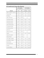
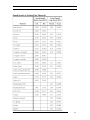
Sound Velocity and Viscosity of Common Liquid ............................................................................ 63
8.4
Sound Velocity of Common Materials .............................................................................................. 63
8.5
Sound Velocity in Water (1 atm) at Different Temperatures.............................................................. 64
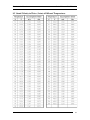
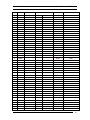
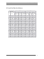
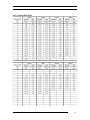
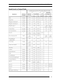
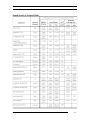
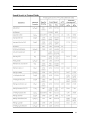
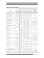
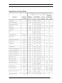
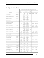
8.6 Common Pipe Dimensions…………………………………………………………………………….65
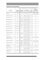
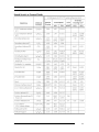
8.7 Common Pipe Dimensions (DIN)……………………………………………………………………..70
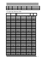
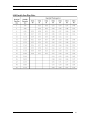
8.8 Cement Lined Pipes liner thicknesses…………………………………………………………………..74
Sierra Instruction Manual
Series 210 Innova-Sonic™ Portable
8.9 Cast Iron Pipe Data……………………………………………………………………………………….75
8.10 Ductile Iron Pipe Data…………………………………………………………………………………..76
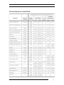
8.11 Sound Speeds in Various Fluids…………………………………………………………………………77
8.12 Addendum for High Temperature transducer installation…………………………………………….…91
8.13 Sound Speed in Various Pipe Materials……………………………………………………………….…92
Sierra Instruction Manual
Series 210 Innova-Sonic™ Portable
1 Product Overview
1.1 Introduction
The INNOVA SONIC PORTABLE Ultrasonic Liquid Flow Meter consists of a flow sensor (two ultrasonic
transducers), a flow transmitter and a Personal Digital Assistant (PDA).
The Model 210 INNOVA SONIC PORTABLE Ultrasonic Flowmeter is a state-of-the-art universal transit-time
flowmeter designed using SLSI technology and low-voltage broadband pulse transmission. While principally
designed for clean liquid applications, the instrument is tolerant of liquids with the small amounts of air
bubbles or suspended solids found in most industrial environments. The 210 INNOVA SONIC PORTABLE
features many advantages:
1. Designed using SLSI technology to offer you such advantages as minimized hardware, low
operating voltage, multipulse transmission, low power consumption, high reliability, enhanced
adaptability and reasonable protection against interference. Optimized intelligent signal
self-adapting processing function eliminates the need for circuit adjustment
2. Easy data acquisition and processing. By using the PDA data acquisition and processing program of
the 210 INNOVA SONIC PORTABLE, you can perform data acquisition and processing
conveniently. Using the PDA, you can also perform such operations as browsing the collected data,
making statistical analysis, displaying graphs, etc. The PC applications of the 210 INNOVA SONIC
PORTABLE make it even easier to implement the above operations or print data tables.
3. Clear, user-friendly operating interface. The fully-windowed software supplied with this instrument
allows users to set parameters or types easily, including British or Metric measurement units, pipe
size, pipe material, wall thickness, fluid type, output signal, etc. The setup guide of the PDA makes
it more convenient for users to configure the setup parameters, display settings and output settings.
Instead of memorizing a large number of commands, you can complete these configurations simply
by following the instructions on the screen. Different settings can be saved as different files that can
be recalled easily.
4. Easy to install, small in size and easily portable. Plug in stereo-type connectors make cable
connections easy. This product is small in size and light in weight supporting battery-powered
operation. Its built-in and standby power supply can provide electricity for up to 24 hours.
5. Features 7-digit positive totalizer, negative totalizer and net flow totalizer working in
parallel, each with a multiplier.
6. The 210 INNOVA SONIC PORTABLE uses a time measurement circuit with high resolution (up to
0.04nS), high linearity and high reliability that, together with its built-in 32 bit digital processor,
ensures higher resolution and a wide measuring range. It can be used in various industries like water
supply and treatment, power supply, district heating, mining, petroleum, chemistry, food processing
and so forth. Its typical applications include:
a) Flow measurement of any homogeneous liquid that is capable of transmitting sonic waves,
such as water, sewage, sea water, acid and alkaline liquid, edible oil, diesel oil, crude oil,
alcohol, beer, etc.
b) Applications in power plants or thermal power, heating, metallurgy, mining, petroleum,
chemistry, food, pharmaceutical, and other sections of the industry.
c) Applications in energy efficiency testing, water management, flow tracking, computerized flow
management, network system monitoring and so forth.
IM-210-D
1
Sierra Instruction Manual
Series 210 Innova-Sonic™ Portable
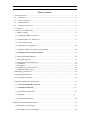
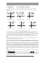
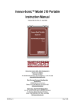
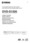
1.2 Theory of Operation
The transit time measurement theory applies to the 210 INNOVA SONIC PORTABLE Ultrasonic Liquid
Flowmeter.
Figure 1-1 Typical Transit Time Schematic Diagram
The distribution of fluid velocity in a pipe varies with the cross-section, with the flow velocity at the center of
the pipe faster than the velocity near the pipe wall. The distribution of fluid velocity in a pipe can be shown in
as a velocity distribution cross-sectional diagram. Based on the mathematical model of the cross-sectional
velocity distribution in the pipe and the settings of the flowmeter, average velocity can be calculated, and then
the volumetric flow can be calculated according to the average velocity of the medium and the cross-sectional
area of the pipeline.
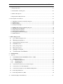
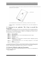
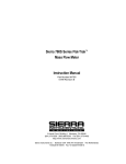
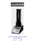
1.3 External Features
The 210 INNOVA SONIC PORTABLE incorporates the following external features:
◆A PDA is connected with the transmitter via Bluetooth wireless communication. The PDA can serve
as your personal digital assistant when not used for measurement.
◆Direct input/output terminal connections on the panel for easy operation.
◆Battery power supply with battery recharge port.
◆Die-cast aluminum chassis
◆Analog 4-20 mA output Cable
Figure 1-2 Outline Drawing of the Flowmeter (in mm)
IM-210-D
2
Sierra Instruction Manual
Series 210 Innova-Sonic™ Portable
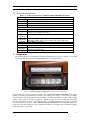
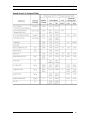
1.4 Technical Specifications
Table 1-1 Technical Specifications of INNOVA SONIC PORTABLE Flow Meter
Performance
Flow range
0~±12m/s (0~±40ft/s)
Accuracy
±1% of measuring value
Repeatability 0.2%
Pipe size
Clamp-on: 25~5000mm (1″~200″)
Functional
Outputs
Analog output: 0/4~20mADC (max load 750Ω)
12VDC (10~36VDC) Battery Power (continuous operation of main battery
Power supply
8 hours + spare battery for 24 hours)
Display and
PDA
Operation
Transmitter: -40℃~60℃
Temperature
Measuring medium: -40℃~80℃(standard); -40℃~150℃(high temp.)
Humidity
0~99%RH, non-condensing
Physical
Transmitter
Aluminum case
Encapsulated design
Transducer
Standard cable length: 5m
Weight
Transmitter +Transducer: approximately 2. 8kg
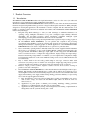
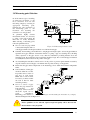
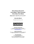
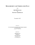
2 Components
The 210 Portable Innova Sonic Digital Correlation Transit Time Flow meter is comprised of 3 essential
components; The Electronics unit, the Palm PDA Interface, and the Transducers.
Figure 2-1 INNOVA SONIC PORTABLE Panel and Connection Diagram
Shown in Figure 2-1 from left to right on the panel of the 210 INNOVA SONIC PORTABLE are the battery
recharge port (charge the transmitter and connect to the standby power supply), power switch, power light
(red), run indicator (green), upstream transducer connector, downstream transducer connector, 4~20mA output
connector and a connector for function expansion. The unit is battery powered and when fully charged will
have an operational life of 8 hours on the internal battery. An additional external battery may be connected
to increase the life up to 24 hours. The 210 INNOVA SONIC PORTABLE Ultrasonic Liquid Flowmeters are
powered by 12V batteries. Batteries can be recharged and standby power supply can be connected through the
battery recharge port on the panel.
IM-210-D
3
Sierra Instruction Manual
Series 210 Innova-Sonic™ Portable
Warning
Only use the supplied charger to charge the batteries.
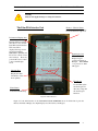
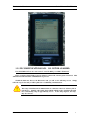
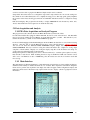
The Palm PDA Interface Unit
ID Area – Window Frame
For use with Data Acquisition
mode and alternate setup mode
Information-Display Area
Displays Meter feedback
info, Error Codes, and all
Data Window information
This area will be
displayed in large-screen
mode when running
M00~M04 commands and
Flow~Velo~+Total~-Total
short cut keys. Press any
point in this area to return
to the normal display
mode.
Input Display Area
Displays keypad
operation information.
Example: When MENU
1 1 is pressed, an “M11”
will appear.
Shortcut Keys
Display the main
information of the
meter quickly.
Keypad area
Use the PDA stylus
and the keypad for
data entry, setup and
all other keypad
functions.
Home Button
Launches Palm Desktop
Figure2-3 Main Interface
Figure 2-3 is the main interface of the 210 INNOVA SONIC PORTABLE. It can be divided into 5 parts: the
ID area, Information Display area, Input Display area, Shortcut key and Keypad.
IM-210-D
4
Sierra Instruction Manual
Series 210 Innova-Sonic™ Portable
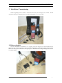
3 Installation / Commissioning
Check the packing list and contents to ensure that all necessary and ordered parts are on hand. Should
any parts be missing or damaged, please contact Sierra Instruments as soon as possible.
3.1 Battery charging.
Once the instrument is determined to be complete, locate the chargers for both the Palm and the
Electronics unit. Place both units on charge until the Palm Battery status indicates fully charged and the
LED on the Charger for the Electronics unit glows green. If the Electronics Charger LED glows red, then it
is not fully charged.
IM-210-D
5
Sierra Instruction Manual
Series 210 Innova-Sonic™ Portable
3.1.1 Turning the 210 Innova Sonic On
The 210 INNOVA SONIC PORTABLE runs a self-diagnostics program after a power up. If it detects any
failure, the error message associated with the failure will be displayed (see Troubleshooting). Once the
self-diagnostics process is completed, the instrument starts working automatically with the parameters that
were entered during the last setup.
Since the 210 INNOVA SONIC PORTABLE uses overlap processing internally with time-sharing technology,
operating the keypad (the keypad displayed on the PDA screen) will not affect the measurement process.
Measurement, computing, keyboard input, displaying, printing, serial port operation and input/output are
referred as “events”, each of which works independently. For example, user’s modification of date and time
will not affect other tasks not related to date and time.
If the instrument is properly installed, it enters into normal operation mode when the power is turned on, and
an ”*R” is displayed on the top left-hand corner of the screen.
When using the instrument for the first time or installing it at a new location, parameters for the new location
must be input. The instrument will permanently hold these parameters until the user modifies them.
When the transducer is removed or any parameter is changed, the instrument readjusts its settings
automatically to work with the new parameters.
When in service, the instrument always completes its tasks simultaneously, regardless of the display window
where the task is performed. Tasks including measurement and output are carried out normally. Each time the
unit is powered on, the instrument enters into the display window it displayed when last powered off.
To ensure a faster communication setup, enter the Palm Home Desktop before powering off the Palm. When
the Palm is turned on again, it will come back to the Desktop, allowing the user to select the Sierra
Instruments 210 Innova Sonic Program.
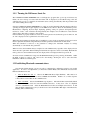
3.2 Establishing Bluetooth communications.
Once the unit is fully charged, you are now ready to commence the configuration setup for your specific
application. In order to accomplish this, you must first establish Bluetooth Communications between the
Palm and the Electronics unit.
1. Turn the Electronics unit on. Observe the RED LED Power light illuminate. This must be in
sequence, the Electronics SHALL be turned on FIRST, then the Palm. Failure to do so in this sequence
could result in a lack of Blue Tooth Communications.
2. Turn on the Palm. Observe the PALM Boot up Sequence. The unit will then automatically launch
the Sierra 210 Innova Sonics and search for BlueTooth devices. It may show a list of compatible
devices to communicate with. Select the FLOXXX device if there are multiple devices listed. It will
then establish communications and you should observe the Green/Amber Run light on the Electronics
flashing while communicating…
IM-210-D
6
Sierra Instruction Manual
3.2.1 IF COMMUNICATIONS FAIL.
Series 210 Innova-Sonic™ Portable
DO NOT BE ALARMED.
First, ENSURE the Electronics unit is turned on and the RED power LED is Illuminated.
In the event that a Data Window appears asking for a Password, enter the password of 1234. This
will unlock the unit and allow communications to proceed.
Should the Palm not discover the Electronics unit, you will see the following screens. Simply
follow the steps below and you will be guided to re-establishing communications.
Note
The range of the Bluetooth Communications is a function of the level of battery life in
both devices. Initially, with a fully charged Palm and Electronics, the Bluetooth with
have a functioning range of approximately 30 feet. As the charge depletes, the range
may also decrease.
IM-210-D
7
Sierra Instruction Manual
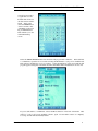
Series 210 Innova-Sonic™ Portable
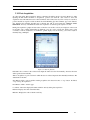
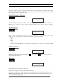
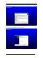
On the Palm, you will see
“Serial Number Error”
Select OK.
Palm will search again for
Bluetooth Devices.
If none are found, you
will see “Application
Error”. Application
Functions will be invalid
due to wrong connection
or wrong serial number.
Select OK.
IM-210-D
8
Sierra Instruction Manual
Series 210 Innova-Sonic™ Portable
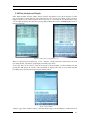
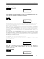
You will now be back to
a regular Innova Sonic
Portable 210 screen, but
the data windows will be
blank. At this point
select the HOME button
on the lower left corner
of the Palm, as shown in
Fig 2-3 Main Interface.
This will take you to the
main Palm Desktop
screen.
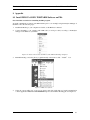
Under the APPLICATIONS ICON select the Sierra 210 program and re-launch it. If this still fails
to communicate, repeat the above, but after selecting the Home Button, cycle power to the Palm unit.
This will force the Palm into a re-boot sequence. Select the OK button on the screen until the 210
program appears stating that some functions will be unavailable until communications are restored.
If you are still unable to communicate, activate the Reset function on the back of the Palm. This
will force a reboot and recycle the Palm software, again, once the Palm software is completely
booted up, the 210 will automatically launch.
IM-210-D
9
Sierra Instruction Manual
Series 210 Innova-Sonic™ Portable
If further attempts to establish Bluetooth communications fail, contact Sierra Instruments for
assistance.
3.3 Configuring for your application. “The 8 Steps to successful flow
measurement.”
Once you are communicating with the electronics, the unit will have the last programmed information.
You will need to enter the parameters for your new application, (assuming they are different from the last
measured location). The following information is required to be programmed into the unit in order to
successfully measure the flow in a given application.
MENU 11:
MENU 12:
MENU 13:
MENU 14:
MENU 16:
MENU 20:
MENU 23:
MENU 24:
MENU 25:
Pipe Outer Diameter
Pipe Wall Thickness
Pipe Inner Diameter (if you enter the OD and Wall, the ID will self compute)
Pipe Material
Liner Material (if any)
Fluid Type
Transducer Type (for the 210 Portable, it will either be Standard, or High Temp depending
on which you have in your kit)
Transducer Mounting Style (Z, V, N, or W mounting configuration, see section XXX
below)
READ Transducer Spacing
Once these values are programmed in, you may mount the transducers, connect the cables and select
Menu 00 and begin reading flow! We will discuss basic data entry here, and then detail the mounting styles.
See Section 4 Entering Data in the Palm Menu for details on exactly how to accomplish this.
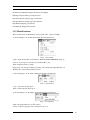
3.3.1 Alternative Method for Application Programming.
On the ID Area – Window Frame (See Fig 2-3 Main Interface above) if you tap once in the Blue Window
frame, two selectable tabs appear.
Utility and Options.
IM-210-D
10
Sierra Instruction Manual
Series 210 Innova-Sonic™ Portable
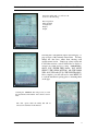
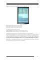
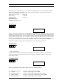
Under the Utility Tab, you will see the
choices for the following;
Data Acquisition
Table & Graph
Configuration
Display
Output
Selecting the Configuration Option will bring up a 1
page synopsis of the currently entered data. You may
change the data here, rather than entering each
separate menu section. Simply tap a data section and
it will either activate a cursor in that label or display a
selection box with choices to enter. IMPORTANT!
ONCE YOU ENTER THIS DATA, YOU MUST
SELECT THE SEND BUTTON, OR THE PALM
WILL NOT UPLOAD IT TO THE ELECTRONICS.
Once complete, you will still need to enter MENU 25
to read the transducer spacing prior to mounting them
on the pipe.
Selecting the OPTIONS Tab will provide you with
the Instrument Serial Number and Software Version
Data.
The other options under the Utility Tab will be
discussed in detail later in this manual.
IM-210-D
11
Sierra Instruction Manual
Series 210 Innova-Sonic™ Portable
3.4 ENTERING DATA IN THE PALM MENU
In order to input the required data, you must navigate to that data window. Page 35 has all the data
windows outlined in a chart format. So, to enter the Pipe Outer Diameter, we need Menu 11. Navigate to
Menu 11 by pressing the MENU and “1”, “1” keys on the Palm.
Observe the data window with the existing Pipe Outer Diameter Displayed in the Display section on the Palm.
To change this data and input the new pipe dimensions, press the ENT Key. {This is the enter key and will
be referred to as the Enter key from this point in the manual.} When you select the enter key, you will see a
cursor that looks like this >. At this point, simply type in the data and press the enter key again. This will
over write the existing information in the Palm and save the new data.
For example, to input a pipe outer diameter of 12.85, perform the following steps: press MENU 1
1 to
enter Window No.11 where the last held Pipe Outer Diameter value will be displayed, then press ENT. A “>”
Symbol will appear. Then type the new data
Pipe Outer Diameter
1
2
.
8
5 then press ENT
>
Once complete with the new Pipe Outer Diameter, select the Down Arrow key. This will take you to the
next sequential Data Window, Pipe Wall Thickness…
Using the same procedure as above, with the Wall Thickness data, enter the Pipe Wall thickness and then
continue with the Down Arrow until you have reached the Transducer spacing data window. At this point
you are ready to install the transducers. Ensure that you have entered the correct data for each of these data
windows;
MENU 11:
Pipe Outer Diameter
MENU 12: Pipe Wall Thickness
MENU 13: Pipe Inner Diameter (if you enter the OD and Wall, the ID will self compute)
MENU 14: Pipe Material
MENU 16: Liner Material (if any)
MENU 20: Fluid Type
MENU 23: Transducer Type (for the 210 Portable, it will either be Standard, or High Temp depending
on which you have in your kit)
MENU 24: Transducer Mounting Style (Z, V, N, or W mounting configuration, see section XXX
below)
MENU 25: READ Transducer Spacing
IM-210-D
12
Sierra Instruction Manual
Series 210 Innova-Sonic™ Portable
3.5 Transducer Mounting Methods
Four transducer-mounting methods are available. They are respectively: V method, Z method, N method and
W method. The V method is primarily used on small diameter pipes (DN100~300mm, 4”~12”). The Z method
is used in applications where the V method cannot work due to poor signal or no signal detected. In addition,
the Z method generally works better on larger diameter pipes (over DN300mm, 12”) or cast iron pipes.
The N and W methods are not commonly used. They are used on smaller diameter pipes (< DN50mm, 2”).
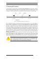
3.5.1Transducer Spacing
The space between the front edges of the two transducers is considered as the standard transducer spacing.
After entering the required parameters, check the data displayed in Window No.25 and space the transducers
accordingly. There are two small pointers on the sides of the transducer racks. The spacing is from point to
point as shown below.
Spacing Pointers
3.5.2 Transducer Mounting Inspection
Check to see if the transducer is installed properly and if there is an accurate and strong enough ultrasonic
signal to ensure proper operation and high reliability of the transducer. It can be confirmed by checking the
detected signal strength, total transit time, delta time as well as transit time ratio.
The “mounting” condition directly influences the flow value accuracy and system reliability. In most instances,
applying a wide bead of sonic coupling compound lengthwise on the face of the transducer and sticking it to
the outside pipe wall will give good measurement results. However, the following inspections still need to be
carried out in order to ensure high reliability of the measurement.
IM-210-D
13
Sierra Instruction Manual
Series 210 Innova-Sonic™ Portable
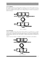
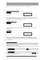
3.5.3 V Method
The V method is considered as the standard method. It usually gives a more accurate reading and is used on
pipe diameters ranging from 25mm to 400mm (1~16”) approximately. Also, it is convenient to use, but still
requires proper installation of the transducer, contact on the pipe at the pipe’s centerline and equal spacing on
either side of the pipe.
Figure 2-6 V Method
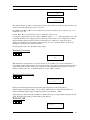
3.5.4. Z Method
Z method is preferable when normal operation with V method is not possible due to poor signal
reception caused by large diameter pipe, heavy scale deposits on the inner pipe wall and the liner,
or the presence of suspended solids in the fluid. When Z method is used, sound is transmitted directly
through the pipeline without any traverse (also referred to as single beam path distance), and signal loss is
minimized.
Z method is used on pipe diameters over 200mm (8”), Z method is recommended for actual installation.
Figure 2-7 Z Method
IM-210-D
14
Sierra Instruction Manual
Series 210 Innova-Sonic™ Portable
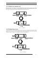
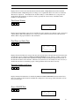
3.5.5 N Method (not commonly used)
With the N method, the sound waves traverse the fluid three times and bounce twice off the pipe walls ( three
beam path distance). It is suitable for small pipe diameter measurement. The measurement accuracy can be
improved by extending the transit distance with the N method (uncommonly used).
Figure 2-8 N Method
3.5.6 W Method (Rarely Used)
As with the N method, the measurement accuracy can also be improved by extending the transit distance with the
W method. The sound wave traverses the fluid four times (four beam path distance) and bounces three times
off the pipe walls. It is suitable for very small pipe (diameters less than 50mm, 2”).
Figure 2-9 W Method
IM-210-D
15
Sierra Instruction Manual
Series 210 Innova-Sonic™ Portable
3.6 Measuring point Selection
Of all flowmeter types, installing
an ultrasonic flowmeter is the
most convenient. You can start
measuring simply by selecting an
appropriate measuring point,
inputting the pipe parameters at
the measuring point to the
flowmeter and attaching the
transducer onto the pipeline.
;PUMP
CHECK VALVE
5D
GOOD
STORAGE TANK
10D
NEVER
To guarantee highly accurate
measurement results, it is necessary
to select a pipe section where the
fluid flow is evenly distributed.
When selecting a measuring point,
follow the guidelines below:
IF PIPE FULL
FLOW
10D
5D
GOOD
Choose a section of pipe, which
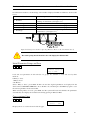
Figure 2-10 Measuring Point Selection
is always full of liquid, such as a
vertical pipe with flow in the upward direction or a full horizontal pipe.
Generally, the measuring point should have a straight pipe run length equal to at least 10 pipe diameters
upstream and 5 pipe diameters downstream. If there is a pump, a pipe tee, adjusting valve, throttling
orifice, expansion of the pipe section or any other flow disturbance producing elements above the
measuring point, the straight pipe section upstream should be longer. For a horizontal pipe, transducers
are usually fixed at the 9 and 3-o’clock position of the pipe.
Avoid attaching the transducers at the 6 and 12 o’clock position to prevent signal attenuation caused by
deposition at the bottom of the pipe or air bubbles and air pockets in the top of the pipeline.
Ensure that the pipe surface temperature at the measuring point is within the transducer temperature
limits.
Scale formation of inner pipe
should be taken into account.
If possible, select a section of
pipe free of scale inside.
When such a section cannot
be located, you must consider
the scale as liner for better
measuring accuracy.
Choose a section of pipe
NEVER
where the pipe material is
homogeneously
and
compactly formed and the
ultrasonic signal can be
easily
transmitted.
Measuring point selection is
illustrated in Figure.2-10 and Figure.2-11.
10D
5D
10D
GOOD
5D
NEVER
10D
5D
GOOD
10D
5D
5D
GOOD
10D
GOOD
FLOW
Figure 2-11 Installing the Transducers (example)
Note
If these guidelines are not followed, signal strength and quality will be affected, and
measurement accuracy degraded.
IM-210-D
16
Sierra Instruction Manual
Series 210 Innova-Sonic™ Portable
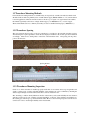
3.7 Mounting the Transducers
As shown in figure 2-12, the transducers of the INNOVA SONIC PORTABLE are integral within a convenient
slide ruler. Magnets are built in the slide ruler. For magnetically conductive pipe materials (such as carbon
steel), you can stick the slide ruler directly onto the pipe outside wall to fix it as shown in figure 2-13. For
non-magnetic conductive pipe materials, you can attach the slide ruler onto the pipe by using pipe clamps.
Figure 2-12 Slider Ruler with Integrated Transducers
Prior to installing the transducers, clean up the pipe surface where the transducers are to be mounted. Remove
any rust, scale or loose paint and choose a section of sound conducting pipe for installing the transducers.
Any pipe insulation materials must be removed so that the transducers may have a direct connection to the
pipe surface. Apply a wide bead of sonic coupling compound down the center of the face of each transducer.
To install the transducers, if both transducers are in a single mounting rack, {see figures 2-14 through 2-18
below} set the established spacing from Menu 25 between the transducers. Tighten the locking ring on top
of each transducer. Using the magnetic racks, place the transducers on the pipe surface. Gently loosen the
transducer locking rings so that the self contained springs push the transducers tightly against the pipe surface.
If the transducers are in separate individual racks, set one rack on the pipe, measure the required spacing from
the pointer on the rack and place the 2nd rack in position such that the distance between pointers meets the
MENU 25 spacing dimension.
For Nonmetallic pipes, use the same procedure as above, however, secure the mounting racks to the pipe
surface with the included pipe straps. Alternative methods to secure the racks to the pipe surface could
include Cable Tie Wraps or even Elastic Bungee Cords. Any device used to hold the racks to the pipe
surface should ensure that the racks are held securely, and the transducers are tight against the pipe surface.
Note
The 2 transducers must be fixed at the front position (i.e. 3 or 9 o’clock position of the
pipe) to prevent signal loss which can be caused by sediment along the bottom of the
pipe or air bubbles and air pockets along the upper part in the pipe.
IM-210-D
17
Sierra Instruction Manual
Series 210 Innova-Sonic™ Portable
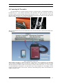
3.8 Connecting the Transmitter
Once the transducers are securely mounted on the pipe, connect the cables to each transducer and then to
the Electronics box. Care should be taken here as the transducer cable ends are keyed to fit into the
transducers wiring connection and then fastened with a threaded connector. The opposite end is a stereo type
plug that simply inserts into the corresponding Upstream and Downstream connection point. Once these 2
cables are securely connected, you are ready to read the flow.
The upstream transducer cable has red terminal ends and downstream transducer cable has blue terminal ends.
See Figure 2-2.
Figure 2-2 Transducer Connection
When installing transducers to relatively small pipes {sizes under 8” in most applications}, the transducer
spacing displayed in MENU25 may be less than 7.5” (190mm), then we can install the transducers in single
slide ruler track. The installation method is unscrewing a transducer off the track at first, as is shown in figure
2-14, then install the two transducers to one track face-to-face as shown in figure 2-15. Accordingly, as shown
in figure 2-16, the flow meter works as usual. Exercise caution during this procedure as the transducers are
spring loaded in the racks.
IM-210-D
18
Sierra Instruction Manual
Series 210 Innova-Sonic™ Portable
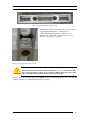
Figure2-14 Unscrewing transducer from the track
Figure 2-15 install the two transducers to one track
Figure 2-16 installing the transducers to one track for measuring
When finished installing both transducers in a single rack, they should appear as shown in the photo below,
Figure 2-17. The oval transducer crystals should be facing each other. They are designed to send signals
back and forth to one another, and if they are installed backwards, they will not function.
IM-210-D
19
Sierra Instruction Manual
Series 210 Innova-Sonic™ Portable
Figure 2-17 both transducers in one rack
Each transducer has a flow direction arrow or an Upstream
/ Downstream Identification. See Figure 2-18.
Additionally, each rack has the flow direction arrow
depicted on it. Ensure the arrows point in the correct
direction to ensure proper operation.
Figure 2-18 Up stream transducer label
Note
The 2 transducers must be fixed at the front position (i.e. 3 or 9 o’clock position of the
pipe) to prevent signal loss which can be caused by sediment along the bottom of the
pipe or air bubbles and air pockets along the upper part in the pipe.
Once the cables are connected, simply select MENU 0 0 and you will display the flow rate. You can then
use the shortcut keys for additional flow information as desired.
IM-210-D
20
Sierra Instruction Manual
Series 210 Innova-Sonic™ Portable
3.9 Ensuring a Quality Flow Measurement
Once the cable are connected, if you select Menu 0 0 you will be taken to the main flow display. If all is
correct, you will see the flow rate, total and a Status Code of *R on the display area. At this point you may
select MENU 9 0 to enter the Diagnostics portion of the data windows.
3.9.1 SIGNAL STRENGTH & QUALITY
Menu 9 0 will provide the Signal Strength and Quality
readings. You want the SS to be above 60 and the Q to be
above 50. If these values are above those limits, you have a
good reliable and accurate flow reading. The Signal Strength
is a measure of how much transmitted signal is being received
by the alternate transducer. The display will show both the
Upstream and Downstream signals. The Quality is a measure
of the electronics processing the information, and
distinguishing between noise and true flow signal.
See
Figure 6-1.
Figure 6-1 Menu 90
3.9.2 TRANSIT TIME RATIO
Figure 6-2 Menu 91
IM-210-D
Menu 9 1 will provide a display of TOM /
TOS ratio.
See Figure 6-2.
This is a
measurement of the actual VS the Calculated
Time of Flight for the flow signal. TOM is the
Time of Flight Measured, TOS is the Time of
Flight Selected.
The “Calculated” or
“Selected” Time of Flight is what the
instruments expects to see based on the
application you programmed it for.
For
example, you program a 6” SCH 40 carbon steel
pipe with water as a fluid, it expects to see a
certain value for the time of flight. The
instrument compares this expected value to the
actual measured value and displays it as a ratio
in %. As long as you are within 3%, (100 +/-3)
then you will be with in published accuracy
specifications’. If TOM/TOS varies by greater
than 3%, something is incorrect in the
programming or transducer placement.
21
Sierra Instruction Manual
Series 210 Innova-Sonic™ Portable
3.9.3 Total Time and Delta Time
Menu 93 will provide “Total Time and Delta Time”
which indicates the condition of the installation. The
measurement calculations in the flowmeter are based
on the two parameters. Therefore, when “Delta Time”
fluctuates widely, the flow and velocities fluctuate
accordingly. This means that the signal quality
detected is too poor. It may be the result of poor
pipe-installation conditions, inadequate transducer
installation or incorrect parameter input.
Generally, “Delta Time” fluctuation should be less
than ±20. Only when the pipe diameter is too small
or velocity is too low can the fluctuation be wider.
3.9.4 Warnings
1. Pipe parameters entered must be accurate; otherwise the flowmeter will not work properly.
2. During the installation, apply enough coupling compound to stick the transducer onto the pipe wall. While
checking the signal strength and Q value, move the transducer slowly around the mounting point until the
strongest signal and maximum Q value can be obtained.
3. Check to be sure if the mounting spacing is in accordance with the one displayed in Window M25.
4. If the signal strength is always displayed as 0.00, there is no signal detected. Thus, it is necessary to check
that the pipeline related parameters have been entered accurately. Check to be sure the transducer mounting
method has been selected properly, the pipe is not worn-out, and the liner is not too thick. Make sure there
is there is indeed fluid in the pipe or that the transducer is not very close to a valve or elbow, and there are
not too many air bubbles in the fluid, etc.
5. ENSURE THAT THERE IS INDEED FLUID IN THE PIPE. This has been stated earlier, but on
numerous occasions, the instrument is installed, the indications are poor Quality and low Signal Strength,
only to have the use begin to suspect the instrument as malfunctioning. After further review, it was
determined that the pipe was actually EMPTY…
3.9.5 4-20mA Current Output
The 4~20mA current output connects to the 5-pin din jack on the panel. With an accuracy of 0.1%, The
current output of the 210 INNOVA SONIC PORTABLE is fully programmable and can be set to various
output modes such as 4~20mA or 0~20mA. Use Window M55 to select the output mode.
The max load of 4-20mA DC is 750Ω. Exercise care on polarity when connecting.
IM-210-D
22
Sierra Instruction Manual
Series 210 Innova-Sonic™ Portable
4.0 Functional Technical Data Information
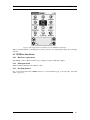
4.1 Key Functions of the Keypad
The keypad has the following functions:
Table 2-1 Key functions
Key
Function
0
Numeric key: 0
1
Numeric key: 1
2
Numeric key: 2
3
Numeric key: 3
4
Numeric key: 4
5
Numeric key: 5
6
Numeric key: 6
7
Numeric key: 7
8
Numeric key: 8
9
Numeric key: 9
·
Value key: decimal point
▲▲▲▲
MENU
Delete key: Clears the last character on the Input Display
Menu key: pressing this key displays “M” on the Input
Display
ENT
Enter key
▲/+
Double function key: page up or positive sign
▼/-
Double function key: page down or negative sign
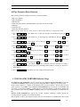
4.2 Shortcut Key Operation and Display
The shortcut keys provide for a quick display of the main information of the ultrasonic flowmeter. You can get
the corresponding information by pressing the key directly.
4.3 Keypad Operation
The 210 INNOVA SONIC PORTABLE flowmeter is windows-based. All parameter inputs, instrument setup
and displayed measurement results are subdivided into more than 100 independent windows. Users can input
parameters, change settings and display measurement results by “visiting” the specific windows. Windows
are numbered in double digit format (including the ”+”) from 00 to 94, then +0, +1, etc. Each window number,
or window address code, has a specific meaning. For example, Window No.11 displays Pipe Outer Diameter
parameters; Window no.25 displays Transducer Mounting Spacing. See “Window Description” for further
information.
The shortcut method to access a window is to press MENU with the stylus in any mode and then press the
double-digit window address code. For example, to input or check Pipe Outer Diameter parameters (Window
IM-210-D
23
Sierra Instruction Manual
no.11), you can simply press MENU 1
Series 210 Innova-Sonic™ Portable
1 .
There are three types of windows:
1) Data,e.g. M11, M12 ;
2) Options,e.g. M14;
3) Display only,e.g. M00, M01.
To check the corresponding parameters, visit the data window. To change the numerical value of that window,
first press the ENTER key to activate the cursor >, enter the new data value, then press ENT to confirm.
4.4 Serial Number of the Program
The INNOVA SONIC PORTABLE ultrasonic liquid flowmeter is equipped with a PDA exclusively designed
for this flowmeter. Every time the PDA is started, it runs the INNOVA SONIC PORTABLE first. If the PDA is
not properly connected to the flowmeter transmitter or the software is unauthorized (the serial number on the
“about” menu is not identical to that of the transmitter), the software will ask the user to make a proper
connection or install the correct serial number (the so-called correct serial number is the serial number of the
flowmeter that is identical to the serial number listed in the “About” menu of the supplied PDA). A wrong
serial number prohibits normal use. Connecting with an incorrect serial number will cause all functions except
“comm” key to be disabled. If you want to exit INNOVA SONIC PORTABLE, press ”OK” and then press
the ”HOME” icon (located at the lower left corner of the PDA) to return to the main interface of the PDA
operating system. You may then use all PDA functions as available.
If you press “About” in the ID area with the stylus, the system will display the serial number of the software
and related copyright, version information. While measuring, you can display the display-only data in full
screen by press the corresponding information display area (This operation is limited to M00~M04 and
shortcut keys Flow, Velo, Total, -Total). Press any point on the screen to return to the normal display.
4.5 Window Descriptions
Window keys and their display contents are listed below:
M00~M09 Display windows: Used to display flow rate, positive total, negative total, net total,
velocity, date & time, analog inputs for present flow, present operation and flow results
today.
M10~M29 Initial parameter setup windows: Used to enter pipe outer diameter, pipe wall thickness,
fluid type, transducer type, transducer mounting and spacing, etc.
M30~M38 Flow units selection and totalizer option operating windows: Used to select a system of units of
measurement. You can choose from flowmeter units such as gallons and cubic feet, or turn on/off
each totalizer as well as performing ”reset” for them.
M40~M49 Include: Flow correction operating window and Network IDN window (No.46), System Lock
window (No.47), Keypad Lock window (No.48), etc.
M55~M83 Input and output setup windows: Current Loop Mode Select, 4mA or 0 mA Output Value,
RS-232C Setup, Low FO Frequency, LCD Contrast Adjustment, etc.
M90~M94 Diagnoses: Signal Strength Quality (Window No.90), TOM/TOS*100 (Window No.91),
Flow Sound Velocity estimated by measurement (Window No.92), Total Time and Delta
Time of the measured signal (Window No.93), Reynolds Number and K Factor of the
Instrument (Window No.94).
M+0~M-0 Appendix: Power On/Off Time, Total Working Hours, On/Off Times etc.
IM-210-D
24
Sierra Instruction Manual
Series 210 Innova-Sonic™ Portable
4.6 Pipe Parameter Entry Shortcuts
The following parameters should be entered for normal measurement:
1. Pipe outer diameter
2. Pipe wall thickness
3. Pipe material
4. Liner material parameters (including thickness and sound velocity, if needed)
5. Fluid type
6. Transducer type
7. Transducer mounting methods
Follow the procedure below to enter the above-mentioned parameters by keypad shortcuts:
1. Press MENU
key.
1
1
to enter Window No.11, then enter the pipe outer diameter and press the ENT
2. Press MENU
conform.
1
2
to enter Window No.12, then input pipe wall thickness and press ENT key to
3. Press MENU 1
4 to enter Window No.14, then press ENT key, scroll the ▲/+ or ▼/- key to
select pipe material, and press the ENT key.
4. Press MENU 1
6 to enter Window No.16, then press ENT key, scroll the ▲/+ or ▼/- key to select
liner material, and press the ENT key.
5. Press MENU 2
0 to enter Window No.20, then press ENT key, scroll the ▲/+ or ▼/- key to select
a fluid type, and press the ENT key.
6. Press MENU 2
3 to enter Window No.23, then press ENT key, scroll the ▲/+ or ▼/- key to select
a transducer type, and press the ENT key.
7. Press MENU
2
4
to enter Window No.24, then press ENT key, scroll the ▲/+ or ▼/- key to select
a transducer-mounting method, and press the ENT key.
8. Press MENU 2
5 to enter Window No.25, then accurately install the transducer according to
displayed transducer mounting spacing and selected mounting method (Refer to Installing the Transducers
in this chapter).
9. Press MENU
0
1 to enter Window No.01 to display measurement result.
5. INNOVA SONIC PORTABLE Software Usage
The INNOVA SONIC PORTABLE software contains two parts: INNOVA SONIC PORTABLE.prc that runs
on the PDA and UFMData data processing program working under Microsoft Windows operating system.
Under normal conditions, to complete all measurement tasks and data acquisition, data browsing and setup
guide operations, only the PDA software INNOVA SONIC PORTABLE.prc is needed. If you need further data
processing, copy the data from PDA to your PC and carry out statistical analysis, graphic display, printing and
other operations on the data using UFMData (UFMData will be provided and will need to be installed in your
PC).
INNOVA SONIC PORTABLE.prc exploits the powerful computing capabilities of PDA, offering the
following functions in addition to normal measurement:
Data Acquisition: Collects data from the flowmeter and stores it in the memory of the PDA. The collected data
IM-210-D
25
Sierra Instruction Manual
Series 210 Innova-Sonic™ Portable
can be browsed in a table or graph on the PDA and simple analysis can be conducted.
Setup Guide: Allows the meter to be configured in steps with a setup wizard. Users can save the settings in a
file, which can be recalled directly later on to simplify the setup process. The setup guide greatly simplifies
the operation of the meter, allowing personnel who are unfamiliar with the flowmeter to configure its settings
easily.
Full Screen Display: The program has the ability to display MENU00~04 and shortcut keys Flow, Velo,
+Total, -Total in full screen view. Operators can check the data easily.
5.1 Data Acquisition and Analysis
5.1.1 PDA Data Acquisition and Analysis Program
This program stores the collected data into the PDA’s Flash memory in the form of files.
For 210 Series Portable kits equipped with the Palm TX, the data is stored on the SD card. The Data Files
may be accessed by starting the “Card Reader” program while attached to your PC. This will allow you to
transfer the data files to your PC for use with the UFM Data program.
For those 210 kits Equipped with the Palm Tungsten T5 model PDA, the data files are stored in the following
directory. Press the “file” icon in the PDA window and go to the following directory: palm\programs\210.
You can see four directories: INNOVA SONIC PORTABLE, Display, Output, and Setup. The “INNOVA
SONIC PORTABLE” directory is used for storing the collected flowmeter data, “Output” for storing output
setup files of the flowmeter, “Display” for storing the display setup files of the flowmeter and “Setup” for
storing setup and configuration files of the flowmeter.
During data acquisition, 1800 data points can be collected each hour (i.e. each data point requires 2 seconds).
Data amount for each hour is 144K. Assuming the data storage of the PDA is 128M, each extension card is
able to store over 900 hours of data or 160000 data points. If needed, users can choose extension cards with
more storage.
5.1.2 Main Interface
The main interface is illustrated in Figure 3-1. The main menu is divided into two items: Utility and Options.
Submenus under Utility are further classified into two modules: Data Acquisition and Table & Graph are
menus used to perform data acquisition and display data table and graph, while Configuration, Display and
Output are menus used for flowmeter setup. Options menu is used to display software copyright and version
information.
Figure 3-1 Main Menu
IM-210-D
26
Sierra Instruction Manual
Series 210 Innova-Sonic™ Portable
5.1.3 Data Acquisition
To collect data, click “Data Acquisition” menu to enter Data Acquisition mode as shown in Figure 3-2. After
inputting the File Name and Time of Acquisition, operators can click the “start” button to enter data
acquisition mode. The Data that can be collected include: date & time, flow rate, flow velocity, net total flow,
positive Total flow, negative total flow, Electronic Serial Number, pipe inner diameter, pipe outer diameter,
pipe material, liner material and fluid type. Collected data will be stored under the “INNOVA SONIC
PORTABLE” directory of the PDA extension card. Acquisition of each data point requires 2 seconds.
During data acquisition, graphs and data values of the flow rate and flow velocity are displayed on the screen
in real time, each of them distinguished by different colors. If a curve exceeds the display range of the
coordinate, it will be readjusted to be within the optimal display area. If necessary, you can also adjust it
manually using a multiplier.
Figure 3-2 Data Acquisition
File Name: Give a name for the collected data. Input the name above the line manually, otherwise the name
will be generated automatically.
Time of Acquisition: A period of time in which the data is collected. Input the time manually in minutes. The
default time is 120 min.
Start Button: Click to start acquisition. During acquisition, this button becomes a “stop” button. If clicked,
“stop” can stop the acquisition.
Done Button: Click to exit this page.
Coordinate: Curves that display Flow Rate and Flow Velocity during data acquisition.
Red Box: Displays the value of the Flow Rate.
Blue Box: Displays the value of the Flow Velocity.
IM-210-D
27
Sierra Instruction Manual
Series 210 Innova-Sonic™ Portable
5.1.4 Data Analysis and Graph
Select “Table & Graph” from the “Utility” menu to enter the data analysis mode as shown in Figure 3-3. This
page is presented as a table where the date & time, flow rate, flow velocity, net totalizer, positive total flow,
negative total flow of the collected data are shown in the form of a data table. To view the data more easily,
you can adjust the display time interval by pressing different Time buttons. Press Left/Right/Up/Down arrow
buttons to turn page.
Figure 3-3 Data Processing Table Screen
There are 4 buttons below the main page: “Load”, “Analyze”, “Graph” and “Done”. These buttons are used
for loading data file, data analysis, graph display and exiting respectively.
“Load” page: Press “Load” button to enter the Load page as shown in Figure 3-4. After clicking a file and
pressing the “OK” button, the contents of the selected file are displayed in a table. You can delete data files
from this page by selecting a file and pressing the “Delete” button.
Figure 3-4 Load Data
“Analyze” page: Click “Analyze” button to enter Data Analyze page as shown in Figure 3-5. This table shows
IM-210-D
28
Sierra Instruction Manual
Series 210 Innova-Sonic™ Portable
the analysis results of the flow rate and flow velocity in the “Data Table”.
Figure 3-5 Data Analyze
Qmax: Maximum values of flow rate and flow velocity;
Qmin: Minimum values of flow rate and flow velocity;
Qavg: Average values of flow rate and flow velocity;
Dev: Deviation of flow rate and flow velocity;
UPmax: Maximum upwards variable rate of flow rate and flow velocity;
DPmax: Maximum downwards variable rate of flow rate and flow velocity;
“Graph” Page: Click “Graph” button to enter Data Curve Graph page as shown in Figure 3-6.
Data Curve Graph page displays curves of flow rate, flow velocity, net totalizer for the current file. Different
curves are shown in different colors, which are indicated by the boxes with filled-in colors. Below the boxes
are curve names that the boxes indicate. You can adjust the display area of a curve by using a multiplier. The
time below the coordinate shows the time range of the curve currently displayed on the screen. You can
browse through the page using Left/Right arrow button, or move data points using Left/Right triangle button.
When clicking a point within the graph display area, a cursor intersecting with the curve appears. At the same
time, the value of the curve at the intersection point is displayed.
IM-210-D
29
Sierra Instruction Manual
Series 210 Innova-Sonic™ Portable
Figure 3-6 Data Curve Graph
5.2 UFMData Data Analysis and Printing Program
Note
Skip this section if you will not use a PC to process the collected data.
Running under the Windows operating system (Windows98 or above) at a PC terminal, the UFMData data
analysis and printing program is used to process the ultrasonic flowmeter data collected by the PDA. The
purpose of this program is to supplement the data processing function of the PDA. This program allows users
to display graphs, print or save the files in Excel format, or browse and analyze the collected data in a table,
enabling users to manage the flowmeter data more conveniently.
Flowmeter data are stored under the INNOVA SONIC PORTABLE directory of the PDA. You can set the
PDA to “Driver Mode” and connect it with your PC.
Note
For information about how to connect the
TungstenT5_handbook_CS.pdf in the PDA CD-ROM.
PDA
with
your
PC,
see
The main window of this program is divided up into 4 pages: Data page, Graph page, Analyze page,
Configuration page.
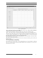
5.2.1 Data Browsing and Printing
After the program starts, the data browsing page will be displayed as shown in figure 3-7. This page allows
you to browse and print the loaded data in a table, or adjust the display time of the data.
IM-210-D
30
Sierra Instruction Manual
Series 210 Innova-Sonic™ Portable
Figure 3-7 PC Data Table
“Open” button: Press this button to read in the flowmeter data files under “INNOVA SONIC PORTABLE”
directory. Theses files are data collected by the PDA.
“Graph” button: Press this button to jump to the “Graph” page, where data are displayed in graphs.
“Print…” button: Press this button to print the table. Basic printing settings can be set in the Print dialog box.
“Time Unit” button: These buttons are used to adjust the display time. Available time units include 2 sec, 10
sec, 30 sec, and 60 sec. The default unit is 2 sec. When a time unit other than 2 sec is selected, the data in the
table will be displayed and printed according to the selected time interval.
Below the data table, the “File” text box shows the File Path, “Rec” shows the number of the data and “Time”
shows the time range for data acquisition.
The contents of the data table are: date & time, flow rate, flow velocity, net total flow, positive total flow and
negative total flow.
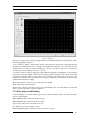
5.2.2 Graph display and printing
Click “Graph” button in the data table to enter the Graph display page as shown in Figure 3-8. This page
allows you to display and print loaded data by graphs intuitively. Users can adjust the color of the curve or
change display unit as required.
IM-210-D
31
Sierra Instruction Manual
Series 210 Innova-Sonic™ Portable
Figure3-8 Graph
This page is divided up into 2 parts: the graph display area with black background is the main page and the
left is the graph display setup area.
“Curve” check box: Placing a check mark to the left of the graph name displays the corresponding graph in
the graph area. Clicking the color box to the right of the graph name changes the color of the graph. You can
change the text color of the coordinate by clicking the color box to the right of “Text Color”, or change the
coordinate grid color by clicking “Grid Color” color box.
“Coordinate” check box: Select to display the graph at different magnifications. Magnification can be changed
in the range of 10-4~108 (default is 100). Once it is changed, the curve displayed on the vertical ordinate will
be changed accordingly. “Time”: Used to change range of the time scale. 1mul stands for 50 sec per scale,
2mul for 25 sec, 5mul for 10 sec and 10mul for 5sec. Once it is changed, the curve displayed on the horizontal
ordinate will be changed accordingly.
“Reset” button: Press to restore the colors of the curves into defaults.
“Print” button: Press to print the graph.
At the bottom of the page, the “File” text box shows the File Path; “Rec” shows the number of the data and
“Time” shows the time range for the data acquisition.
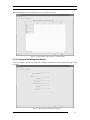
5.2.3 Data Analysis and Printing
As shown in Figure 3-9, the data analysis page is used to perform statistical analysis on collected flowmeter
data. Its contents include:
Qmax: Maximum values of flow rate and flow velocity;
Qmin: Minimum values of flow rate and flow velocity;
Qavg: Average values of flow rate and flow velocity;
Dev: Deviation of flow rate and flow velocity;
UPmax: Maximum upwards variable rate of flow rate and flow velocity;
IM-210-D
32
Sierra Instruction Manual
Series 210 Innova-Sonic™ Portable
DPmax: Maximum downwards variable rate of flow rate and flow velocity;
Figure 3-9 Data Statistical Analysis Page at PC Terminal
5.2.4 Configuration Information Display
As shown in Figure 3-10, this page displays the configuration information of the flowmeter. This page cannot
be printed.
Figure 3-10 Configuration Information Display
IM-210-D
33
Sierra Instruction Manual
Series 210 Innova-Sonic™ Portable
Flowmeter Serial Number: Displays flowmeter serial number;
Fluid Type: Displays fluid type being measured;
Pipe Outer Diameter: Displays pipe outer diameter;
Pipe Inner Diameter: Displays pipe inner diameter;
Pipe Material: Displays pipe material;
Liner Material: Displays liner material.
5.2.5 Menu Functions
There are three menus in the Menu bar of the program: “File”, “Edit” and “Help”.
As shown in Figure 3-11, the File submenu has the following functions:
Figure 3-11 File Menu
“Open”: Opens the data files stored under the “INNOVA SONIC PORTABLE” directory;
“Save As”: Saves reports as text files (.txt) and Excel files (.xls);
“Print”: Prints data tables or graphs;
“Page Setup”: Sets the paper settings for printing, such as Paper Size, Paper Direction, etc.
“Print Preview”: Previews the printing contents.
As shown in Figure 3-12, the “Edit” submenu has the following functions:
Figure 3-12 Edit Menu
“Copy”: Copies the selected region.
“Find”: Searches the data in the report.
As shown in Figure 3-13, the “Help” submenu has the following functions:
Figure 3-13 Help Menu
“Help”: Operating instructions for this software.
“About”: Software copyright, version information, and so on.
IM-210-D
34
Sierra Instruction Manual
Series 210 Innova-Sonic™ Portable
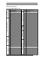
6 Windows Display Codes
6.1 List of Windows Display Codes
Flow Rate/POS Totalizer
55
CL Mode Select
03
Flow Rate/NEG Totalizer
56
CL 4mA or 0mA Output Value
04
05~
Date Time/Flow Rate
08
System Error Codes
09
Flow Today
10
Pipe Outer Perimeter
11
Pipe Outer Diameter
12
Pipe Wall Thickness
13
Pipe Inner Diameter
14
Pipe Material
15
Pipe Sound Velocity
82
Date Totalizer
16
Liner Material
83
Automatioc Correction
17
Liner Sound Velocity
18
Liner Thickness
20
Fluid Type
21
22
Fluid Sound Velocity
Fluid Viscosity
23
Transducer Type
24
Transducer Mounting
25
Transducer Spacing
+1
Total Working Hours
26
Parameter Setups
+2
Last Power Off Time
27
Cross-sectional Area
+3
Last Flow Rate
28
Hold Previous Data
29
Empty Pipe Setup
30
Measurement Unit
31
Flow Rate Units
+7
Communication Protocol Sselect
32
Totalizer Units
-0
* For expansion
33
Totalizer Multiplier
34
Net Totalizer
Velo
Flow Velocity
35
Positive Totalizer
+Total
Positive Total
36
Negative Totalizer
-Total
Negative Total
37
Totalizer Reset
38
Manual Totalizer
40
Damping
41
Low Flow Cutoff Value
42
43
Set Zero
Reset Zero
44
Manual Zero Point
45
Scale Factor
46
Network ID Address Code
47
System Lock
48
* For expansion
50~54
Network Communication Tester
For expansion
57
CL 20mA Output Value
58
* For expansion
59
CL Current Output
60
Date and Time
61
Software Vertion and ESN
62
* For expansion
63~71
* For expansion
72
Working Timer
73~81
* For expansion
84~89
90
* For expansion
Signal Strength and Quality
91
TOM/TOS*100
92
Fluid Sound Velocity
93
Total Time and Delta Time
94
Reynolds Number and Factor
+0
Power ON/OFF time
+4
ON/OFF Times
+5
Calculator
+6
Medium Sound Velocity Variety Threshold
Flow
Shortcut
Keys
Setup
Options
Flow Rate/Velocity
02
Appendix
FlowUnit
Options
01
* For expansion
49
Diagnosis
Initial Parameter setup
Flow Rate/Net Totalizer
Input/Output
Flow/Totalizer
Display
IM-210-D
00
Sig
Flow Rate
signal Strength and Quality
Aout
Analog Output
Error
Error Code
Comm
Communication Information Between PDA
And Flowmeter
35
Sierra Instruction Manual
Series 210 Innova-Sonic™ Portable
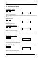
6.2 MENU Display explanation
This section will cover individual menu displays indepth.
Flow Rate/Net Totalizer
MENU 0
0
Flow 0.1154 m3/h *R
NET
+97×1m3
Displays flow rate and net totalizer.
If the net totalizer has been turned off (refer to M34), the net totalizer value displayed is the total prior to its
turn off.
Flow Rate/Velocity
MENU 0
1
Flow 0.1129 m3/h *R
Vel
1.0415
m/s
Displays flow rate and velocity.
Flow Rate/Positive Totalizer
MENU 0
2
Flow 0.1129 m3/h *R
POS
0X1m3
Displays flow rate and positive totalizer.
Select the positive totalizer units in Window M32.
If the positive totalizer has been turned off, the positive totalizer value displayed is the total prior to its turn
off.
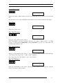
Flow Rate/Negative Totalizer
MENU 0
3
Flow 0.1120 m3/h *R
NEG
0X1m3
Displays flow rate and negative totalizer.
Select the negative totalizer units in Window M32.
If the negative totalizer has been turned off (refer to M36), the value displayed is the total prior to turn off.
Date & Time/Flow Rate
MENU 0
4
03-04-03 15:49:40 *R
Flow
0.1116m3/h
Displays the current date & time and flow rate.
The time setting method is found in Window M60.
IM-210-D
36
Sierra Instruction Manual
Series 210 Innova-Sonic™ Portable
System Error Codes
MENU 0
8
*R-------------System
Normal
Displays the working condition and the system error codes. More than one error code can occur at the same
time.
The explanations of error codes and detailed resolution methods can be found in “Troubleshooting” chapter.
Flow Today
MENU 0
9
Net Flow
Today
321.45
[09
m3
Displays net total flow today.
Pipe Outer Perimeter
MENU
1
0
Pipe Outer Perimeter
518.363
mm
Input pipe outer perimeter in this window.
If the outer diameter is the known parameter, input pipe outer diameter in Window No.11. It is NOT
necessary to enter both Outer PERIMETER & Outer DIAMETER, if you enter one of these values, the
instrument will calculate the other.
Pipe Outer Diameter
MENU 1
1
Pipe Outer
110
Diameter
mm
Input pipe outer diameter in this window, or enter pipe outer perimeter in Window M10. The pipe
outer diameter must range from 1” to 200” (25mm to 6000mm).
Note: Input either pipe outer diameter or pipe outer perimeter.
Pipe Wall Thickness
MENU 1
2
Pipe Wall
6.5
Thickness
mm
Input pipe wall thickness in this window. If the pipe inner diameter is already known, skip this
window and input it in Window M13.
IM-210-D
37
Sierra Instruction Manual
Series 210 Innova-Sonic™ Portable
Pipe Inner Diameter
MENU 1
3
Pipe Inner Diameter
97 mm
Input pipe inner diameter in this window. If the pipe outer diameter (or perimeter) and pipe wall
thickness has been entered, press [▼] to skip this window.
Note: Input either pipe wall thickness or pipe inner diameter.
Pipe Material
MENU 1
4
Pipe Material
[14
0. Carbon Steel
Input pipe material in this window. The following options are available (by[▼]、[▲] buttons or
numerical keys).
0. Carbon Steel
1. Stainless steel
2. Cast Iron
3. Ductile Iron
4. Copper
5. PVC
6. Aluminum
7. Asbestos
8. FiberGlass-Epoxy
9. Other
Refer to item 9 “Other”; it is possible to input other materials, which are not included in previous
eight items. Once item 9 is selected, the relevant pipe sound velocity must be inputted in Window
M15.
Pipe Sound Velocity
MENU 1
5
Pipe Sound Velocity
m/s
Input pipe sound velocity in this window. This function is only used when item 9 “Other” is
selected in Window M14. At the same time, this window cannot be visited. System will calculate
automatically according to the existing parameters.
Liner Material
MENU 1
6
Liner Material
[16
0. None,Liner
Select the liner materials in this window.
The following options are available:
0. None
1. Tar Epoxy
IM-210-D
38
Sierra Instruction Manual
Series 210 Innova-Sonic™ Portable
2. Rubber
3. Mortar
4. Polypropylene
5. Polystryol
6. Polystyrene
7. Polyester
8. Polyethylene
9. Ebonite
10. Teflon
11. Other
Item 11 “Other” is available to input other materials that are not included in the previous list. Once
the “Other” is selected, the relevant liner sound velocity must be inputted in Window M17.
Liner Sound Velocity
MENU 1
7
Liner Sound Velocity
0 m/s
Input liner sound velocity in this window. It can only be visited when item “Other” in Window M16
is selected.
Liner Thickness
MENU 1
8
Liner Thickness [18
0 mm
Input liner thickness in this window. It can only be visited when a definite liner is selected in
Window M16.
Fluid Type
MENU 2
0
Fluid
Type
[20
0. Water
Select fluid type in this window. The following options are available:
0. Water
1. Sea Water
2. Kerosene
3. Gasoline
4. Fuel Oil
5. Crude Oil
6. Propane
7. Butane
8. Other
9. Diesel Oil
10. Castor Oil
11. Peanut Oil
12. Gasoline #90
13. Gasoline #93
14. Alcohol
15. Water (125C)
IM-210-D
39
Sierra Instruction Manual
Series 210 Innova-Sonic™ Portable
“Other” refers to any fluid. The relevant sound velocity must be inputted in Window M21.
Fluid Sound Velocity
MENU 2
1
Fluid Sound Velocity
1482.9m/s
Input fluid sound velocity in this window. It can only be used when item “Other” is selected in
Window M20, i.e. it is unnecessary to input when it is one of the fluids listed in Window M20. The
instrument uses default value.
Fluid Viscosity
MENU 2
2
Fluid Sound
[22
1.0038cST
Input fluid’s kinematics viscosity in this window. It can only be used when item “Other” is selected
in Window M20. To Calculate Centistokes, Divide Centipoises by the Specific Gravity of the
fluid.
Transducer Type
MENU 2
3
Transducer Type [23
0. Standard
For the Innova-Sonic, parameter 0 (standard) should be selected regardless what transducer type is
used.
Transducer Mounting
MENU 2
4
Transducer Mounting
0.
V
Four mounting methods are available:
0.
1.
2.
3.
V
Z
N
W
(V Method, sound waves bounce 2 times)
(Z Method, sound waves do not bounce, but transit the pipe)
(N Method, sound waves bounce 3 times. Small Pipe)
(W Method, sound waves bounce 4times. Very Small Pipe)
Transducer Spacing
MENU 2
5
Transducer
Spacing
148.666 mm
The operator must mount the transducer according to the transducer spacing displayed (be sure that
the transducer spacing is measured precisely during installation). The system will display the data
automatically after the pipe parameters have been entered.
IM-210-D
40
Sierra Instruction Manual
Series 210 Innova-Sonic™ Portable
For different transducers, the meanings of the number displayed in M25 are different. See the table
below:
Transducer selected in MENU23
The meaning of the number displayed in Window MENU23
0.Standard
1.Insertion Type S
2.Insertion Type H
3.Insertion Type E
4.User Type
The distance between the corresponding terminal faces of the
2 clamp-on transducers (See figure 4-1.)
The distance between the centers of the 2 plug-in transducers
The distance between the centers of the 2 plug-in transducers
The distance between the centers of the 2 plug-in transducers
The distance between the corresponding terminal faces of the
2 transducers. (See figure 4-1.)
Figure 4-1 Clamp-on transducer Spacing (Distance Between the 2 Terminal Faces)
Note
The actual spacing must be identical to the value displayed in Window M25.
Initial Parameter Setups and Save
MENU 2
6
Parameter Setups [26
Entry to SAVE
Load and save parameters in this window. 18 groups are available to load and save by three
methods:
0. Entry to Save
1. Entry to Load
2. To Browse
Select “Entry to Save”, press ENT. An ID code and the original parameters are displayed in the
window. Press UP/DOWN ARROW to move the ID code, and then press the ENT key again to save
the current parameter in the current ID..
When selecting “Entry to Load”, press ENT, and the system will read and calculate the parameters
automatically and display the transducer mounting spacing in Window M25.
Cross-sectional Area
MENU 2
7
Cross-sectional Area
31415.9
mm2
Displays the cross-sectional area inside the pipe.
IM-210-D
41
Sierra Instruction Manual
Series 210 Innova-Sonic™ Portable
Holding with Poor Signal
MENU 2
8
Hold with PoorSig [28
NO
Select “Yes” to hold last good flow signal displayed if the flowmeter experiences a poor signal
condition. This function allows continued data calculation without interruption. This would be
used in circumstances of continuous flow, but gaps in the fluid, (air bubbles or slugs of solids)
which pass through the flow stream causing the signal quality to reduce. Once these disturbances
have passed, the Signal Quality should return to a higher value, if holding with Poor Sig is set to
YES, then the meter will keep the existing flow rate during these flow disturbances.
Empty Pipe Setup
MENU 2
9
Empty pipe setup [29
30
This parameter is used to overcome the possible problems that usually show up when the pipe
being measured is empty. Since signals can be transmitted through the pipe wall, the flowmeter
may still read a flow while measuring an empty pipe. To prevent this from happening, you can
specify a value. When the signal quality falls below this value, the measurement stops
automatically. If the flowmeter is already able to stop measuring when the pipe is empty, a value in
the range of 30 to 40 should also be entered in this window to ensure no measurement when the
pipe is empty. It should be understood that the instrument is NOT designed to function correctly
on an empty pipe.
Measurement Units
MENU 3
0
Measurement Units In
0. Metric
Select the measurement unit in this window as follows:
0. Metric
1. English
Factory default is metric.
Flow Rate Units
MENU 3
1
Flow Rate Units [31
m3/h
Select flow rate units and time units.
0. Cubic Meters
1. Liters
2. (American) Gallons
3. Imperial Gallons
4. Million Gallons
5. Cubic Feet
6. American Barrels
IM-210-D
(m3)
(l)
(gal)
(ig)
(mg)
(cf)
(bal)
42
Sierra Instruction Manual
7. Imperial Barrels
8. Oil Barrels
Series 210 Innova-Sonic™ Portable
(ib)
(ob)
The following time units are available:
/Day
/Hour
/Min
/Sec
Factory default is Cubic Meters/hour.
Totalizer Units
MENU 3
2
Totalizer Units [32
Cubic
Meters (m3)
Select totalizer units in this window. The available unit options are as same as those found in
Window M31. Factory default is Cubic Meters.
Totalizer Multiplier
MENU 3
3
Totalizer Multiplier
0.
X0.001
The totalizer multiplier acts as the function to increase the totalizer indicating range. The totalizer
multiplier can be applied to the positive totalizer, negative totalizer and net totalizer at the same
time. The following options are available:
0. x 0.001 (1E-3)
1. x 0.01
2. x 0.1
3. x 1
4. x 10
5. x 100
6. x 1000
7. x 10000(1E+4)
Factory default factor is x1
ON/OFF Net Totalizer
MENU 3
4
Net Totalizer
[34
ON
Turn On or Off the Net totalizer in this window. “ON” indicates the totalizer is turned on, while
“OFF” indicates it is turned off. When it is turned off, the net totalizer displays in Window M00
will not change. Factory default is “ON”.
ON/OFF Positive Totalizer
MENU 3
5
POS
Totalizer
[35
ON
IM-210-D
43
Sierra Instruction Manual
Series 210 Innova-Sonic™ Portable
Turn On or Off the positive totalizer in this window. “ON” indicates the flowmeter will totalize
flow in the positive direction. When it is turned off, the positive totalizer display in Window M02
will not change. Factory default is “ON”.
ON/OFF Negative Totalizer
MENU 3
6
NEG
Totalizer
[36
ON
Turn On/off negative totalizer in this window. “On” indicates the totalizer is turned on. When it is
turned off, the negative totalizer displays in Window M03 will not change. Factory default is
“ON”.
Totalizer Reset
MENU 3
7
Totalizer Reset? [37
Selection
Reset totalizer and all parameters in this window. Press [ENT]; move UP or DOWN arrow to select
“YES” or “NO”. After “YES” is selected, the following options are available:
None
All
NET
POS
NEG.
Using the UP or DOWN Arrows, select the desired totalizer you wish to reset, then press ENT.
Manual Totalizer
MENU 3
8
Manual Totalizer
Press ENT When Ready
The manual totalizer is a separate totalizer. Press ENT to start, and press ENT to stop it. It is used for flow
measurement and calculation.
Damping
MENU 4
0
Damping
[40
10 sec
The damping factor ranges from 0~999 seconds.
0 indicates no damping; 999 indicates the maximum damping.
The function of damping is to display the data smoothly. Its principle is the same as that in a single-section
RC filter. The damping factor value corresponds to the circuit time constant. Usually a damping factor of 3 to
10 is recommended in applications.
IM-210-D
44
Sierra Instruction Manual
Series 210 Innova-Sonic™ Portable
Low Flow Cutoff Value
MENU 4
1
Low Flow Cutoff Val.
0.01 m/s
Low Flow Cutoff is used to make the system display as “0” value at lower and smaller flows to avoid any
invalid totalizing. For instance, if the cutoff value is set as 0.03, system will take all the measured flow values
below ±0.03 as “0”. Usually 0.03 is recommended in most applications.
Set Zero
MENU 4
2
Set Zero
[42
Press ENT to go
When fluid is in the static state, the displayed value is called the “Zero Point”. When the “Zero Point’ is not
at zero in the flowmeter, the difference is going to be added into the actual flow values and measurement
differences will occur in the flowmeter.
Set zero must be carried out after the transducers are installed and the flow inside the pipe is in the absolute
static state (no liquid movement in the pipe). It is imperative that the user understands that simply closing a
valve, or securing a pump will NOT guarantee the complete stoppage of fluid movement in the pipe.
Sufficient time should be allowed for the hydraulic forces in the fluid to subside PRIOR to activating the Set
Zero Command.
Once you are positive of NO FLUID MOVEMENT in the pipe system you may select the Set Zero command
with will adjust the instruments “Zero Point” resulting from different pipe mounting locations and parameters
as compared to the flow calibration laboratory. The measuring accuracy at low flow is consequently enhanced.
Press [ENT], wait approximately 45 seconds.
Press MENU 00 to return to the main flow display and read zero flow.
Activating the “Set zero” while there is flow may cause the flow to be displayed as “0”. If so, it can be
recovered via Window M43.
Reset Zero
MENU 4
3
Reset Zero
[43
No
Select “YES” in this window to reset “Zero Point” which was set by the user. Selecting this
function will reverse the Set Zero command of Menu 42. The previous Zero Setting will be
restored in the flow meter.
Manual Zero Point
MENU 4
4
Manual Zero Point [44
0m3/h
IM-210-D
45
Sierra Instruction Manual
Series 210 Innova-Sonic™ Portable
This method is not commonly used. It is only suitable for experienced operators to set zero under conditions
where it is not preferable to use other methods. Enter the value manually to add to the measured value to
obtain the actual value. For instance:
Actual measured value
= 250 m3/H
Offset Value
= 10 m3/H
INNOVA SONIC
= 240 m3/H
PORTABLE Display
Normally, set the value to “0”.
Scale Factor
MENU 4
5
Scale Factor
[45
1
Due to variations encountered in real field application installations as compared to perfect laboratory
calibration systems, there may exist a circumstance in which the measured flow value disagrees with a
customers know reference value. Causes for these variations can be pipe internal conditions, hydraulic flow
profiles inside the piping systems, etc…Should the “measured” flow value differ from the “real” flow value, a
scale factor can be applied to offset this. For example, should the instrument display 90 GPM, but the
customer reference indicates the flow is actually 100 GPM, a value of 1.1 would be entered in Menu 45.
Ideally, the Scale Factor should remain at its default value of 1 for the highest performance.
System Lock
MENU 4
7
System Lock
[47
**** Unlock ****
“Lock” the instrument.
Once the system is locked, any modification is prohibited in the system, but parameters are still readable.
“Unlock” by the password only. The password is composed of 1 to 4 numbers.(Please contact us if the
password is forgotten.)
CL Mode Select
MENU 5
5
CL Mode
Select
[55
0. 4 - 20mA
Select a CL Output Mode in this window. The following are available parameters:
0.
1.
2.
3.
4.
4-20mA Output Mode
0-20 mA
0-20mA via RS232
4-20mA vs Fluid
20-4-20mA Mode
IM-210-D
set
set
set
set
set
up
up
up
up
up
the output range from 4-20mA
the output range from 0-20mA
to control by Serial Port (205 Series Only)
the output range 4-20mA in flow units (GPM)
the output range from 20-4-20mA
46
Sierra Instruction Manual
Series 210 Innova-Sonic™ Portable
5. 0-4-20mA Mode
6. 20-0-20mA Mode
7. 4-20mA VS. Velocity
set up the output range from 0-4-20mA
set up the output range from 20-0-20mA
set up the output range from 4-20mA in Velocity units (FPS)
Current output characteristics of each mode are shown below. Users can select one mode to meet their
requirements
Output current
Output current
O u tp u t c u rre n t
24mA
24mA
24m A
20m A
4mA
Flow
0m A
Flow
-F20mA
-F4mA
F4mA
F20mA
-F20mA
-F4mA
F4mA
F20mA
Flow
Flow
Flow
Flow
Flow
Flow
Flow
Flow
F20m A
F lo w
F l ow
0 -2 0 m A m o d e o u tp u t
20-0-20mA mode output
20-4-20mA mode output
F lo w
F0m A
O utp u t cu rren t
O utput current
O u tp u t c u rre n t
24 m A
24m A
24m A
20 m A
20m A
20m A
4m A
4m A
F low
Flow
F 4m A
Flow
F 20m A
Fl ow
4-20m A m ode output
F0m A
F lo w
F4 m A
F lu id
velo city
F lo w
0 -4 -2 0 m A m o d e o u tp u t
Flu id v e lo c ity
4m A
F20m A
F20m A
F lu id
velocity
F lu id v elo city / 4 -20 m A o u tp u t
Figure4-2 4-20A Output Characteristics
In six graphs shown above, flow F0mA or F4mA indicates the value that the user entered in Window M57; and
flow F20mA indicates the value that users entered in Window M58. In the 4-20mA and 0-20mA modes, F0mA(or
F4mA)and F20mA can be selected as a positive or negative flow value as long as the two values are not the same.
As for modes 20-4-20mA and 20-0-20mA, the INNOVA SONIC PORTABLE ignores the positive and
negative value of the actual flow; therefore, both F0mA(or F4mA)and F20mA must be selected as positive flow
values.
In mode 0-4-20mA, F0mA must be select as a negative value and F20mA as a positive value. Furthermore, in
mode 4-20mA, the output current is indicated as velocity.
With accuracy better than 0.1%, The CL output of INNOVA SONIC PORTABLE is fully programmable and
can be set to various output modes such as 4~20mA or 0~20mA. Use Window M55 to select the output mode.
Input the flow value represented by 4mA in Window M56 and input the value represented by 20mA in
Window M57. For example, if the flow range of a pipe is 0~1000m3/h, input 0 in window M56 and 1000 in
M57. If the flow range is 1000~0~2000m3/h, without reference of the flow direction, you can use
20~4~20mA mode (select in Window M55) by inputting 1000 in Window M56 and 2000 in M57. If the flow
direction is considered, 0~4~20mA output mode can be selected. When the flow is in negative direction, the
output current is in the range of 0~4mA. When the flow is in positive direction, the output current is in the
range of 4~20mA. Output mode is selected in Window M58. Input “-1000” in Window M56 and “2000” in
M57.
Use Window M58 to validate whether the current loop itself has been “calibrated” or not. To do so, follow the
steps below:
Press MENU 5
8 ENT key. Move out “0mA”, “ 4mA”, “8mA” in turn using ▲/+ or ▼/- and at the same
time measure the output of the current loop with a precise current meter. Calculate the errors between the two
values and check weather the error is in the allowed error range. If not, calibrate the current loop according to
the §3.36 section of this chapter.
IM-210-D
47
Sierra Instruction Manual
Series 210 Innova-Sonic™ Portable
Window M59 allows you to check the current CL output that is varied with the flow.
CL 4mA or 0mA Output Value
MENU 5
6
CL 4mA Output Value
0 m3/h
Set the CL output value according to the flow value at 4mA or 0mA.(4mA or 0mA are determined by the
settings in Window M56). The flow unit’s options are as same as those in Window M31. Once “velocity
4-20mA”is selected in Window M56, the unit should be set as m/s.
CL 20mA Output Value
MENU 5
7
CL 20 mA Output Value
14400 m3/h
Set the CL output value according to the flow value at 20mA. The flow unit is the same as that found in
Window M31.
CL Checkup
MENU 5
8
CL Checkup
[58
Press ENT When Ready
Check if the current loop has been calibrated before leaving the factory. Press ENT, move ▲/+or ▼/separately to display 0mA, 4mA till 24mA, and at the same time, check with an ammeter to verify that CL
output terminals No. 31 and 32 agree with the displayed values. It is necessary to re-calibrate the CL if over
the permitted tolerance.
Analog Output Calibration
Note: Under general conditions, don't perform this operation unless the current value displayed on
Window M58 is not identical to the actual output. Each flowmeter has been strictly calibrated by the
manufacturer before leaving the factory.
Before calibrating the analog input, you must enter the hardware-debugging window using the following
procedure:
Press MENU 0 ENT, input the password “4213068” and press ENT key again to open the window. The
unfolded window is available only in current power-on period. It is automatically closed once you turn off the
power.
Press MENU 1 ENT to enter the calibration mode for CL 4mA output. Measure the output of the current
loop with a precise current meter and at the same time adjusts displayed data by using ▲/+ or ▼/- key. Stop
adjusting when the current meter shows 4.00.
IM-210-D
48
Sierra Instruction Manual
Series 210 Innova-Sonic™ Portable
Then, press ENT key to enter the calibration mode of the CL 20mA output and calibrate it in the same way as
in the 4mA.
Stored in the EEPROM, the results of calibration will not be lost even when the power is off.
CL Current Output
MENU 5
9
CL Current Output [59
0.0000
mA
Displays CL current output. The display of 10.0000mA indicates that CL current output value is 10.0000mA。
If the difference between displaying value and CL output value is too large, the current loop then needs to be
re-calibrated accordingly.
Date and Time Settings
MENU 6
0
YY-MM-DD HH:MM:SS
03-04-04 10:05:04
Date and time modifications are made in this window. The format for setting time setting is 24 hours. Press
ENT, wait until “>” appears, the modification can be made.
Software Version and ESN
MENU 6
1
Ultrasonic Flowmeter
S/N=04071188
Displays software version and electronic serial number (ESN) of the instrument. This ESN is uniquely
assigned to each INNOVA SONIC PORTABLE flowmeter ready to leave the factory. The factory uses it for
files setup and for management by the user.
Working Timer
MENU 7
2
Working Timer
[72
00000011:16:38
Display the totalized working hours of the INNOVA SONIC PORTABLE since last reset. It is displayed by
HH:MM:SS. If it is necessary to reset it, press ENT, and select “YES”.
Date Totalizer
MENU 8
2
Date Totalizer
IM-210-D
[82
49
Sierra Instruction Manual
Series 210 Innova-Sonic™ Portable
0.
Day
00 00-07-18----->
4356.78 m3
This window makes it possible to review the historical flow data totalizer for any day for the last 64 days, any
month for last 64 months and any year for last 5 years.
Press ENT, use the ▲/+ or ▼/- to review totalizer in day, month or year. Press “0” to review by day, “1” for
month and “2” for year.
Use the ▲/+or ▼/- to review the flow total for a specific day, month or year.
For instance, to display the flow total for July 18, 2000, the display “-----------” at the upper right corner of the
screen indicates that it was working properly the whole day. On the contrary, if “G” is displayed, it indicates
that the instrument gain was adjusted at least once. Probably it was offline once on that day. If “H” is
displayed, it indicates that poor signal was detected at least once. Also, it indicates that the operation was
interrupted or problems occurred in the installation.
For details, please refer to the “Troubleshooting” chapter.
Automatic Correction
MENU 8
3
Automatic Correction
YES
With the function of automatic flow correction, the flow lost in an offline session can be estimated and
automatically amended. The estimation is based on the average value, which is obtained from flow rate before
going offline and flow measured after going online the next time, multiplied times the time period that the
meter was offline. Select “On” to enable this function or select “OFF” to disable it.
Signal Strength and Quality
MENU 9
0
Strength+ Quality [90
UP:00.0 DN:00.0 Q=00
Displays the measured upstream and downstream signal strength and overall signal quality Q
Signal strength is indicated from 00.0~99.9. A reading of 00.0 indicates no signal detected, while 99.9
indicates maximum signal strength. Normally the signal strength should be ≥60.0.
Signal quality Q is indicated by 00~99. Therefore, 00 indicates the poorest signal while 99 indicates the best
signal. Normally, signal quality Q value should be better than 50.
TOM/TOS*100
MENU 9
1
TOM/TOS*100
[91
0.0000
IM-210-D
50
Sierra Instruction Manual
Series 210 Innova-Sonic™ Portable
Display the ratio between the actual measured transit time (Time of Flight Measured) and the calculated
transmit time (Time of Flight Suspected) according to user’s requirement. This is in essence an “Actual VS
Theoretical” comparison. Normally the ratio should be 100±3%. If the difference is too large, the user
should check if the parameters are entered correctly, especially the sound velocity of the fluid and the
installation of the transducers.
Fluid Sound Velocity
MENU 9
2
Fluid Sound Velocity
0.0000m/s
Displays the measured fluid sound velocity. Normally this value should be approximately equal to the entered
value in Window M21. If the difference is too large, it probably results from an incorrect value entered in
Window M21 or improper installation of the transducers.
Total Time and Delta Time
MENU 9
3
Total
Time,
Delta
Time
8.9149uS,-171.09nS
Display the measured ultrasonic average time (unit: uS) and delta time of the upstream and downstream (unit:
nS) time. The velocity calculation in INNOVA SONIC PORTABLE is based on the two readings; especially
the delta time will best indicate if the instrument is running steadily. Normally the fluctuation in the ratio of
the delta time should be lower than 20%; Otherwise, the system may not run steadily. It is, then, necessary to
check if the transducers are installed properly or if the parameters have been entered correctly.
Reynolds Number and Factor
MENU 9
4
Reynolds Number [94
0.0000
1.0000
Display the Reynolds number that is calculated by INNOVA SONIC PORTABLE flowmeter and the factor
that is set currently by the flowmeter. Normally this scaling factor is the average of line and surface velocity
factor inside the pipe.
Power ON/OFF Time
MENU +
0
ON/OFF
Time
[+0
Press ENT When Ready
IM-210-D
51
Sierra Instruction Manual
Series 210 Innova-Sonic™ Portable
To view the power on/off time and flow rate for the last 64 update times to obtain the offline time period and
the corresponding flow rate. Enter the window, press ENT to display the last update before the last 64 times of
on/off time and flow rate values. “ON” on right hand indicates that time power is on; “00” on the upper left
corner indicates “00-07-18 12:40:12” the date time; flow rate is displayed in the lower right corner.
Total Working Hours
MENU +
1
Total Work Hours
[+1
00000113:02:08
This function makes it possible to view the total working hours since the INNOVA SONIC PORTABLE left
the factory. The figure on the right indicates that the total working hours since the flowmeter left the factory is
113 hours 2 minutes 8 seconds.
Last Power Off Time
MENU +
2
Last Power Off Time
03-04-04
11:33:02
Displays the last power off time.
Last Flow Rate
MENU +
3
Last Flow Rate
[+3
100.43m3/h
Displays the last flow rate.
Total ON/OFF Times
MENU +
4
ON/OFF
Times
[+4
40
Display total on/off times since the INNOVA SONIC PORTABLE leaves the factory.
Calculator
MENU +
5
Calculator: Input X=
0
This window is a calculator capable of functional operation. How to use: Input the first parameter X, then
IM-210-D
52
Sierra Instruction Manual
Series 210 Innova-Sonic™ Portable
select an operator. If this operation has a second parameter, input the second parameter Y and put the result of
the operation in X. For example:
To calculate 1+2, press MENU + 5 1 ENT, select operator “+” by using ▲/+, and press ENT 2 ENT.
This calculator also has a register function, which can be selected by operator selection.
Note: The calculator can also be used in a measuring process, and the measurement will not be affected.
Shortcut Key for Flow rate
Flow
Flowrate:
+000000E+00m3/h
Displays flow rate, which equals to the contents of Flow when issuing command M00.
Shortcut Key for Flow Velocity
Velo
Flow Velocity:
+000000E+00m/s
Displays flow velocity, which equals to the contents of Vel after issuing command M01
Shortcut Key for POS Total Flow
+Total
POS Total Flow:
+0029383E-2m3
Displays positive total flow, which equals to the contents of POS after issuing command M02.
Shortcut Key for NEG Total Flow
-Total
NEG Total Flow:
+0029383E-2m3
Displays negative total flow, which equals to the contents of NEG after issuing command M03.
Shortcut Key for Signal Strength and Quality
Sig
IM-210-D
53
Sierra Instruction Manual
Series 210 Innova-Sonic™ Portable
SigStrength&Quality:
UP:03.1,DN:45.6,Q=00
Displays signal strength and quality, which equals to the contents displayed in the window after issuing
command M90.
Shortcut Key for Analog Output
Aout
Analog Output(%)
+2.000000E+1
Displays analog output( 4~20mA)information.
Shortcut key for error code
Error
Error Code:
I
Displays error codes during an operation. See chapter 5 for error code contents.
Shortcut Key for Communication Setup
Comm
Communication Setup
Please Wait
Displays the communication condition between the PDA and the Flowmeter. This window Displays ”OK” if
the connection has been made correctly. If not, it displays “Failure”, and you should check the Bluetooth
Communications. Under normal conditions, you should not conduct detection repeatedly using this button,
otherwise you may cause the PDA to shutdown.
6.3 Displaying Data in Full-Screen View
If you press the data display area with the stylus while measuring, display contents will be displayed in full
screen and large font. Press any point in the full screen display area to return to normal display mode. This
function makes it easier for operators to read data.
Only MENU 00~04 and the display contents of shortcut key Flow, Vel, +Total, -Total can be displayed in full
screen view.
IM-210-D
54
Sierra Instruction Manual
Series 210 Innova-Sonic™ Portable
6.4 Defaults Restoration
Press MENU
defaults.
3
7 key. After opening Window No.37, press
.
◄ directly to reset the settings to
6.5Analog Voltage Output
Connect a 250Ω resistance to the current loop in parallel to transform 4~20mA into 1~5V voltage output.
6.6 Check Flow of Every Day/Month/Year
Window M82 allows you to read flow data history and the operating state of the instrument in the past 64
days.
00 00-07-21 -------Press MENU 8
2 key and select sub item No.0 “Day”. Then, the
>
3412.53 M3
character is displayed as shown in right. The “00” – “63” in the upper left
corner stands for serial number, the “00-07-21” in the middle for date and
the
“--------” in the upper right corner for operating state. Only “--------” being displayed on the status bar
indicates the instrument was working properly at that working day. If there are other characters displayed, see
the error code instruction for reference. The data 3412.53 in the bottom shows the net total flow of that
working day.
To read the total flow of a month, press MENU
To read the total flow of a year, press MENU
8
8
2
2
key and select sub item No.1 “Month”.
key and select sub item No.2 “Year”.
6.7View Electronic Serial Number and Other Details
Every INNOVA SONIC PORTABLE ultrasonic flowmeter is distinguished by a unique electronic serial
number (ESN) for ease of manufacturer and users’ management. (Note: Faked flowmeters don't have unique
serial numbers or not at all). Use window M61 to view ESN and the type of the machine.
Window M+1 allows you to view the total working time since the flowmeter leaves the factory.
Window M+4 allows you to view total On/Off times since the flowmeter leaves the factory.
See “Troubleshooting” chapter for detailed information.
7 Troubleshooting
With a highly reliable design, the INNOVA SONIC PORTABLE has a very low failure rate. However,
problems may occur due to unskilled operation, setting errors or measurements made in an extremely
undesirable working condition. For this reason, the INNOVA SONIC PORTABLE has made improvements in
its self-diagnostic function. Problems detected are displayed in time order in code form on the upper right
corner of the LCD screen. Hardware malfunctions, though generally checked after power is on, can also be
detected while the device is working normally. Information about other problems caused by wrong settings or
undesirable working conditions can also be displayed. There are two kind of errors displayed in INNOVA
SONIC PORTABLE:
(1) Error messages that are displayed during self-test after the power is switched on. After entering the
measurement mode, if there is an error, " * F" will be displayed at the top left corner of the screen. Check
displayed information and perform specific steps according to the following tables. If problems persist,
please contact the manufacture.
(2) Errors concerning the specific signal received or wrong settings can be displayed in Window M08 in
the form of an error code. Errors and solutions are listed in Table 6-1 and 6-2.
IM-210-D
55
Sierra Instruction Manual
Series 210 Innova-Sonic™ Portable
Table 6-1 Self Test Information, Cause and Solution
Error information
Cause
Rom Parity Error
* System ROM illegal or error
So lutio n
* Contact the manufacturer
* Restart or contact
manufacturer
* Restart or contact
manufacturer
the
Stored Data Error
* Stored Data Error
Hardware error
* Fatal error in sub CPU circuit
PF or Timer Slow Error
PF or Timer Fast Error
* System clock error
* Contact the manufacturer
CPU or Interruption error, retry
*
Stored Data Error
* System RAM has problems
Time Or Batt Error
* System time chip error
When keys are pressed, no
response from the screen No
display or display disorderly.
*Disoperation,poor cable contact
on the panel or insufficient
power supply in the PDA
* restart
* Restart or contact the
manufacturer
* Restart or contact the
manufacturer
* soft reset;
* Check whether the cables on
the panel are contacted well
or the PDA battery is fully
charged.
No response when keys are
pressed on the PDA. Press
“comm”,display“OK”.
*The software is unauthorized,
that is the “Serial Number” in the
“About” window isn’t identical to
the serial number on the
transmitter.
No response when keys are
pressed on the PDA. Press
“comm”,display“Failure”
When turning off the PDA, the
response of the program is too
slow or no response at all.
The format of the data displayed
in the Information Display area is
not correct.
IM-210-D
the
*If
you
bought
several
flowmeters,
please
check
whether the“Serial Number”is
identical to that of the
transmitter. Otherwise, contact
the company.
*The cable connected to the PDA *Check the cable
is broken or not properly
linked.
*The shutdown sequence in not *On
completing
the
correct. The transmitter
is measurement, the PDA program
switched off first.
should
be
closed
before
switching off the transmitter.
*False communication between *Restart the program connection
PDA and Transmitter.
or press “Comm” to reconnect.
56
Sierra Instruction Manual
Series 210 Innova-Sonic™ Portable
Table 6-2 Error Code, Cause and Solution
Cod e
*R
*J
Corresponding display on
M08 menu
System Normal
SCPU Fatal Error
Signal Not Detected
Cause
*System operates normally
* Hardware failure
* No signal received
* A poor contact between
transducers and the pipe, or
too little couplant supplied
* the transducer has not been
installed properly.
*I
*Too much scale formation
in the inside wall
Solution
* contact the company
* Make sure the transducer is
close to the pipe. Use sufficient
couplant.
* Make sure no rust stains, no
oil, paint and no rust on the pipe
surface. Use flat file to clean the
pipe surface.
* Check the original settings
* You can only clean the
couplant or change the pipe. But
under normal conditions you can
try to change a measuring point.
* Wait until the liner saturated
and solidified.
*H
Low Signal Strength
Poor Signal Quality
*H
*E
Current Loop over 20mA
(Ignore it if the measuring
process don't use current
output)
See Table 5.1
* New liner
* Poor signal
* Same cause of the above
* Poor signal quality
*
Include
the
above
mentioned causes
* 4-20mA current loop
overflow over 120%.
* Wrong current loop output
settings
* Self-checking error
*F
*G
Adjusting Gain=>S1
Adjusting Gain=>S2
Adjusting Gain=>S3
Adjusting Gain=>S4
(Displayed in M00,M01,
M02,M03 windows)
*K
Empty pipe , M29 menu
settings
IM-210-D
* Perpetual hardware failure
* These 4 steps mean that the
machine is going on the gain
adjustment, preparing for the
normal measurement. If the
machine stops on S1 or S2,
or shifts between S1 and S2,
it denotes that the received
signal is too low or the
waveform is not good. The
reasons may include all
above-mentioned causes.
No liquid in the pipe or
wrong settings
* The same as above column
* Same as above
* Recheck the settings (see M56
operation instruction) or make
sure the actual flow is not too
big.
* Restart the device and observe
the information displayed on the
screen.
If
the
problem
persists ,contact the company.
* contact the company.
If
there is liquid in the
pipe ,input ”0” in the M 29
menu.
57
Sierra Instruction Manual
Series 210 Innova-Sonic™ Portable
8 Appendix
8.1 Install INNOVA SONIC PORTABLE Software on PDA
Note: Read this section before reinstalling the PDA program.
To install communication software (take Palm DeskTop V4.1 as an example) using the HotSync Manager of
the PDA , follow the following steps:
1. Install Palm Desktop to your computer. For details, see the PDA user’s manual.
2. Connect the PDA to your computer with USB cable (or serial port cable) according to the HotSync
manager on the Windows system disk.
Figure 6-1 Choose Sync Connection Mode of the PDA and Desktop Computer
3.
Run Palm Desktop, and select [View] -> [Quick Install] on the menu or click “Install” icon.
Figure 6-2 Run sync software
4.
Select the corresponding user on the pop-up window and click [Add] button to install communication
software application INNOVA SONIC PORTABLE.prc and serial number file Dslp.pdb. See Figure 6-3.
IM-210-D
58
Sierra Instruction Manual
Figure 6-3.
Series 210 Innova-Sonic™ Portable
Select a User Name and Sync File INNOVA SONIC PORTABLE.prc and
Dslp.pdb
5.
Click the HotSync icon of the PDA or press the HotSync key on the sync jack and install the application
according to the clue.
Figure 64 Press sync button to synchronize
6.
For application icons displayed on the PDA after installation, see Figure 6-5.
IM-210-D
59
Sierra Instruction Manual
Series 210 Innova-Sonic™ Portable
Figure6-5 The Application Icons Displayed on the PDA After Installation
When not using the PDA for a extended period of time, or there is not enough battery charge, please recharge
it in time.
8.2 UFMData Installation
8.2.1 Hardware requirements
CPU: PII266 or faster,Memory: 64M or more,Display resolution: 1024*768 or higher。
8.2.2 OS Requirements
Windows 98SE 4.10.2222A or later, IE4.01 or later.
8.2.3 Installing Method
Step 1: Open Setup file in the UFMData directory to enter installation page, as shown in Fig. 6-6. Click
“Next” to proceed.
IM-210-D
60
Sierra Instruction Manual
Series 210 Innova-Sonic™ Portable
Figure 6-6 UFMData Setup Interface
Step 2: Select an installation directory. Click “Next” to accept the default directory. If you want to change the
installation directory, click “Browse” to select a directly and click “next” to continue to the next step, as
shown in Figure 6-7.
Figure 6-7 Select a UFMData Installation Directory
Step 3: Select a program folder, then click “Next” to enter next step, as shown in Figure 6-8.
IM-210-D
61
Sierra Instruction Manual
Series 210 Innova-Sonic™ Portable
Figure 6-8 Select UFMDataProgram Folder
Step 4: Click “Finish” to finish installation, as shown in Figure 6-9.
Figure 6-9 Finish UFMData Installation
IM-210-D
62
Sierra Instruction Manual
Series 210 Innova-Sonic™ Portable
8.3 Sound Velocity and Viscosity of Common Liquid
Liquid
Water 20℃
Velocity of
Sound
(m/s)
1482
Viscosity
(mm2/s)
Liquid
Velocity of
Sound (m/s)
1.0
Glycerin
1923
1180
0.80
Water 50℃
1543
0.55
Gas
1250
Water 75℃
1554
0.39
66#Gas
1171
Water 100℃
1543
0.29
80#Gas
1139
Water 125℃
1511
0.25
0#Gas
1385
Water 150℃
1466
0.21
Benzene
1330
Water 175℃
1401
0.18
Methylbenzene
1340
Water 200℃
1333
0.15
Toluene
1170
Water 225℃
1249
0.14
938
Water 250℃
Acetone
1156
0.12
Tetra
chloromethane
Kerosene
1420
1190
Petroleum
1290
Carbonyl
1121
Pine oil
1280
Ethanol
1168
Alcohol
1440
Ketone
Viscosity
(mm2/s)
Chloroethylene
1050
Dagang jet fuel
1298
1310
Daqing 0#jet fuel
1290
Acetaldehyde
1180
Arachis oil
1472
Glycol
1620
Castor oil
1502
1.5
0.69
2.3
0.82
8.4 Sound Velocity of Common Materials
Pipe
Material
Steel
ABS
Aluminum
Brass
Cast iron
Bronze
Fiber
glass-epoxy
Glass
Polyethylene
PVC
IM-210-D
Sound Velocity (m/s)
Liner Material
3206
2286
3048
2270
2460
2270
PTFE
Titanium
Cement
Bitumen
Porcelain enamel
Glass
Sound Velocity
(m/s)
1225
3150
4190
2540
2540
5970
3430
Plastic
2280
3276
1950
2540
Polyethylene
PTFE
Rubber
1600
1450
1600
63
Sierra Instruction Manual
Series 210 Innova-Sonic™ Portable
8.5 Sound Velocity in Water (1 atm) at Different Temperatures
IM-210-D
64
Sierra Instruction Manual
Series 210 Innova-Sonic™ Portable
8.6 Common Pipe Dimensions (English)
OD
1/8"
INCH
0.405"
SCHEDULE
10
WALL
ID
10S
0.049"
0.307"
1/8"
0.405"
STD
40
40S
0.068"
0.269"
1/8"
0.405"
XS
80
80S
0.095"
0.215"
1/4"
0.540"
10
10S
0.065"
0.410"
1/4"
0.540"
STD
40
40S
0.088"
0.364"
1/4"
0.540"
XS
80
80S
0.119"
0.302"
3/8"
0.675"
10
10S
0.065"
0.545"
3/8"
0.675"
STD
40
40S
0.091"
0.493"
3/8"
0.675"
XS
80
80S
0.126"
0.423"
1/2"
0.840"
5
5S
0.065"
0.710"
1/2"
0.840"
10
10S
0.083"
0.674"
1/2"
0.840"
STD
40
40S
0.109"
0.622"
1/2"
0.840"
XS
80
80S
0.147"
0.546"
1/2"
0.840"
160
0.188"
0.464"
1/2"
0.840"
XX
0.294"
0.252"
3/4"
1.050"
5
5S
0.065"
0.920"
3/4"
1.050"
10
10S
0.083"
0.884"
3/4"
1.050"
STD
40
40S
0.113"
0.824"
3/4"
1.050"
XS
80
80S
0.154"
0.742"
3/4"
1.050"
160
0.219"
0.612"
3/4"
1.050"
XX
0.308"
0.434"
1"
1.315"
5
5S
0.065"
1.185"
1"
1.315"
10
10S
0.109"
1.097"
1"
1.315"
STD
40
40S
0.133"
1.049"
1"
1.315"
XS
80
80S
0.179"
0.957"
1"
1.315"
160
0.250"
0.815"
1"
1.315"
XX
0.358"
0.599"
11/4"
1.660"
5
5S
0.065"
1.530"
11/4"
1.660"
10
10S
0.109"
1.442"
11/4"
1.660"
STD
40
40S
0.140"
1.380"
11/4"
1.660"
XS
80
80S
0.191"
1.278"
11/4"
1.660"
160
0.250"
1.160"
11/4"
1.660"
XX
0.382"
0.896"
11/2"
1.900"
5
5S
0.065"
1.770"
11/2"
1.900"
10
10S
0.109"
1.682"
11/2"
1.900"
STD
40
40S
0.145"
1.610"
11/2"
1.900"
XS
80
80S
0.200"
1.500"
11/2"
1.900"
160
0.281"
1.388"
11/2"
1.900"
XX
0.400"
1.100"
2"
2.375"
5
5S
0.065"
2.245"
2"
2.375"
10
10S
0.109"
2.157"
2"
2.375"
STD
40
40S
0.154"
2.067"
2"
2.375"
XS
80
80S
0.218"
1.939"
IM-210-D
65
Sierra Instruction Manual
Series 210 Innova-Sonic™ Portable
OD
INCH
WALL
ID
2"
2.375"
160
SCHEDULE
0.344"
1.687"
2"
2.375"
XX
0.436"
1.503"
21/2"
2.875"
5
5S
0.083"
2.709"
21/2"
2.875"
10
10S
0.120"
2.635"
21/2"
2.875"
STD
40
40S
0.203"
2.469"
21/2"
2.875"
XS
80
80S
0.276"
2.323"
21/2"
2.875"
160
0.375"
2.125"
21/2"
2.875"
XX
0.552"
1.771"
3"
3.500"
5
5S
0.083"
3.334"
3"
3.500"
10
10S
0.120"
3.260"
3"
3.500"
STD
40
40S
0.216"
3.068"
3"
3.500"
XS
80
80S
0.300"
2.900"
3"
3.500"
160
0.438"
2.624"
3"
3.500"
XX
31/2"
4.000"
5
0.600"
2.300"
5S
0.083"
3.834"
31/2"
4.000"
10
31/2"
4.000"
STD
40
10S
0.120"
3.760"
40S
0.226"
31/2"
4.000"
XS
80
3.548"
80S
0.318"
3.364"
31/2"
4.000"
XX
4"
4.500"
5
5S
0.636"
2.728"
0.083"
4"
4.500"
10
10S
4.334"
0.120"
4.260"
4"
4.500"
0.156"
4.188"
4"
4.500"
0.188"
4.124"
4"
4.500"
STD
40
40S
0.237"
4.026"
4"
4.500"
XS
80
80S
0.337"
3.826"
4"
4.500"
120
0.438"
3.624"
4"
4.500"
160
0.531"
3.438"
4"
4.500"
XX
0.674"
3.152"
41/2"
5.000"
STD
40
40S
0.247"
4.506"
41/2"
5.000"
XS
80
80S
0.355"
4.290"
41/2"
5.000"
XX
0.710"
3.580"
5"
5.563"
5
5S
0.109"
5.345"
5"
5.563"
10
10S
0.134"
5.295"
5"
5.563"
STD
40
40S
0.258"
5.047"
5"
5.563"
XS
80
80S
0.375"
4.813"
5"
5.563"
120
0.500"
4.563"
5"
5.563"
160
0.625"
4.313"
5"
5.563"
XX
0.750"
4.063"
6"
6.625"
5
5S
0.109"
6.407"
6"
6.625"
10
10S
0.134"
6.357"
6"
6.625"
0.188"
6.249"
6"
6.625"
STD
40
40S
0.280"
6.065"
6"
6.625"
XS
80
80S
0.432"
5.761"
6"
6.625"
120
0.562"
5.501"
6"
6.625"
160
0.719"
5.187"
6"
6.625"
XX
0.864"
4.897"
IM-210-D
66
Sierra Instruction Manual
Series 210 Innova-Sonic™ Portable
OD
INCH
WALL
ID
7"
7.625"
STD
40
SCHEDULE
40S
0.301"
7.023"
7"
7.625"
XS
80
80S
0.500"
6.625"
7"
7.625"
XX
8"
8.625"
8"
8.625"
10
8"
8.625"
8"
8.625"
8"
8.625"
STD
8"
8.625"
60
8"
8.625"
XS
8"
8.625"
8"
8.625"
8"
8.625"
8"
8"
0.875"
5.875"
5S
0.109"
8.407"
10S
0.148"
8.329"
20
0.250"
8.125"
30
0.277"
8.071"
0.322"
7.981"
0.406"
7.813"
0.500"
7.625"
100
0.594"
7.437"
120
0.719"
7.187"
140
0.812"
7.001"
8.625"
XX
0.875"
6.875"
8.625"
160
0.906"
6.813"
9"
9.625"
STD
40
40S
0.342"
8.941"
9"
9.625"
XS
80
80S
0.500"
8.625"
9"
9.625"
XX
0.875"
7.875"
10"
10.750"
5S
0.134"
10.482"
10"
10.750"
10S
0.165"
10.420"
10"
10.750"
0.188"
10.374"
10"
10.750"
20
0.250"
10.250"
10"
10.750"
30
0.307"
10.136"
10"
10.750"
STD
40
40S
0.365"
10.020"
10"
10.750"
XS
60
80S
0.500"
9.750"
10"
10.750"
80
0.594"
9.562"
10"
10.750"
100
0.719"
9.312"
10"
10.750"
120
0.844"
9.062"
10"
10.750"
140
1.000"
8.750"
10"
10.750"
160
1.125"
8.500"
11"
11.750"
STD
40
40S
0.375"
11.000"
11"
11.750"
XS
80
80S
0.500"
10.750"
11"
11.750"
XX
0.875"
10.000"
12"
12.750"
5S
0.156"
12.438"
12"
12.750"
10S
0.180"
12.390"
12"
12.750"
20
0.250"
12.250"
12"
12.750"
30
0.330"
12.090"
12"
12.750"
STD
0.375"
12.000"
12"
12.750"
40
0.406"
11.938"
12"
12.750"
XS
0.500"
11.750"
12"
12.750"
60
0.562"
11.626"
12"
12.750"
80
0.688"
11.374"
12"
12.750"
100
0.844"
11.062"
12"
12.750"
120
1.000"
10.750"
12"
12.750"
140
1.125"
10.500"
12"
12.750"
160
1.312"
10.126"
IM-210-D
40
80
40S
80S
40S
80S
67
Sierra Instruction Manual
Series 210 Innova-Sonic™ Portable
OD
INCH
14"
14.000"
WALL
ID
0.188"
13.624"
14"
14.000"
0.250"
13.500"
14"
14.000"
20
14"
14.000"
STD
0.312"
13.376"
0.375"
14"
14.000"
40
13.250"
0.438"
13.124"
14"
14.000"
XS
14"
14.000"
60
0.500"
13.000"
0.594"
12.812"
14"
14.000"
14"
14.000"
80
0.750"
12.500"
100
0.938"
14"
14.000"
12.124"
120
1.094"
11.812"
14"
14"
14.000"
140
1.250"
11.500"
14.000"
160
1.406"
16"
16.000"
11.188"
0.188"
15.624"
16"
16.000"
16"
16.000"
10
0.250"
15.500"
20
0.312"
15.376"
16"
16.000"
STD
30
16"
16.000"
XS
40
40S
0.375"
15.250"
80S
0.500"
16"
16.000"
15.000"
60
0.656"
14.688"
16"
16"
16.000"
80
0.844"
14.312"
16.000"
100
1.031"
13.938"
16"
16.000"
120
1.219"
13.562"
16"
16.000"
140
1.438"
13.124"
16"
16.000"
160
1.594"
12.812"
18"
18.000"
0.188"
17.624"
18"
18.000"
10
0.250"
17.500"
18"
18.000"
20
0.312"
17.376"
18"
18.000"
STD
0.375"
17.250"
18"
18.000"
30
0.438"
17.124"
18"
18.000"
XS
0.500"
17.000"
18"
18.000"
40
0.562"
16.876"
18"
18.000"
60
0.750"
16.500"
18"
18.000"
80
0.938"
16.124"
18"
18.000"
100
1.156"
15.688"
18"
18.000"
120
1.375"
15.250"
18"
18.000"
140
1.562"
14.876"
18"
18.000"
160
1.781"
14.438"
20"
20.000"
0.218"
19.564"
20"
20.000"
10
0.250"
19.500"
20"
20.000"
STD
20
40S
0.375"
19.250"
20"
20.000"
XS
30
80S
0.500"
19.000"
20"
20.000"
40
0.594"
18.812"
20"
20.000"
60
0.812"
18.376"
20"
20.000"
80
1.031"
17.938"
20"
20.000"
100
1.281"
17.438"
20"
20.000"
120
1.500"
17.000"
20"
20.000"
140
1.750"
16.500"
20"
20.000"
160
1.969"
16.062"
IM-210-D
SCHEDULE
10S
10
30
40S
80S
10S
10S
40S
80S
10S
68
Sierra Instruction Manual
OD
INCH
22"
22.000"
22"
22.000"
22"
22"
Series 210 Innova-Sonic™ Portable
WALL
ID
10
SCHEDULE
10S
0.250"
21.500"
STD
20
40S
0.375"
21.250"
22.000"
XS
30
80S
0.500"
21.000"
22.000"
60
0.875"
20.250"
22"
22.000"
80
1.125"
19.750"
22"
22.000"
100
1.375"
19.250"
22"
22.000"
120
1.625"
18.750"
22"
22.000"
140
1.875"
18.250"
22"
22.000"
160
2.125"
17.750"
24"
24.000"
24"
24.000"
STD
24"
24.000"
XS
24"
24.000"
24"
24.000"
24"
24.000"
24"
24"
10
10S
0.250"
23.500"
20
40S
0.375"
23.250"
80S
0.500"
23.000"
30
0.562"
22.876"
40
0.688"
22.624"
60
0.969"
22.062"
24.000"
80
1.219"
21.562"
24.000"
100
1.531"
20.938"
24"
24.000"
120
1.812"
20.376"
24"
24.000"
140
2.062"
19.876"
24"
24.000"
160
2.344"
19.312"
26"
26.000"
0.312"
25.376"
26"
26.000"
STD
40S
0.375"
25.250"
26"
26.000"
XS
80S
0.500"
25.000"
28"
28.000"
28"
28.000"
28"
28.000"
20
28"
28.000"
30"
30.000"
30"
30.000"
STD
30"
30.000"
XS
30"
30.000"
32"
32.000"
32"
32.000"
32"
32.000"
32"
32"
34"
34.000"
34"
34.000"
34"
34.000"
34"
34"
10
0.312"
27.376"
40S
0.375"
27.250"
80S
0.500"
27.000"
30
0.625"
26.750"
10
0.312"
29.376"
40S
0.375"
29.250"
80S
0.500"
29.000"
30
0.625"
28.750"
10
0.312"
31.376"
0.375"
31.250"
20
0.500"
31.000"
32.000"
30
0.625"
30.750"
32.000"
40
0.688"
30.264"
10
0.312"
33.376"
0.375"
33.250"
20
0.500"
33.000"
34.000"
30
0.625"
32.750"
34.000"
40
0.688"
32.624"
36"
36.000"
10
0.312"
35.376"
36"
36.000"
STD
40S
0.375"
35.250"
36"
36.000"
XS
80S
0.500"
35.000"
42"
42.000"
STD
40S
0.375"
41.250"
42"
42.000"
XS
80S
0.500"
41.000"
IM-210-D
10
STD
20
STD
STD
69
Sierra Instruction Manual
Series 210 Innova-Sonic™ Portable
42"
42.000"
0.750"
40.500"
48"
48.000"
STD
40
40S
0.375"
47.250"
48"
48.000"
XS
80S
0.500"
47.000"
8.7 Common Pipe Dimensions (DIN)
PIPE SIZES & SCHEDULES
N.B.
inches
N.B.
mm
O.D.
mm
WALL
mm
1
1
1
1
25
25
25
25
33.4
33.4
33.4
33.4
3.4
4.5
6.4
9.1
1¼
1¼
1¼
1¼
32
32
32
32
42.2
42.2
42.2
42.2
3.6
4.9
6.4
9.7
1½
1½
1½
1½
40
40
40
40
48.3
48.3
48.3
48.3
3.7
5.1
7.1
10.2
2
2
2
2
50
50
50
50
60.3
60.3
60.3
60.3
3.9
5.5
8.7
11.1
2½
2½
2½
2½
65
65
65
65
73.0
73.0
73.0
73.0
5.2
7.0
9.5
14.0
3
3
3
3
80
80
80
80
88.9
88.9
88.9
88.9
5.5
7.6
11.1
15.2
XXS
3½
3½
90
90
101.6
101.6
5.7
8.1
STD
XS
40
80
4
4
4
4
4
100
100
100
100
100
114.3
114.3
114.3
114.3
114.3
6.0
8.6
11.1
13.5
17.1
STD
XS
40
80
120
160
5
5
5
5
5
125
125
125
125
125
141.3
141.3
141.3
141.3
141.3
6.6
9.5
12.7
15.9
19.0
IM-210-D
Identification
STD
Schedule
XS,XXS
Number
STD
XS
40
80
160
XXS
STD
XS
40
80
160
XXS
STD
XS
40
80
160
XXS
STD
XS
40
80
160
XXS
STD
XS
40
80
160
XXS
STD
XS
40
80
160
XXS
STD
XS
40
80
120
160
XXS
70
Sierra Instruction Manual
Series 210 Innova-Sonic™ Portable
6
6
6
6
6
150
150
150
150
150
168.3
168.3
168.3
168.3
168.3
7.1
11.0
14.3
18.3
21.9
8
8
8
8
8
8
8
8
8
8
200
200
200
200
200
200
200
200
200
200
219.1
219.1
219.1
219.1
219.1
219.1
219.1
219.1
219.1
219.1
6.4
7.0
8.2
10.3
12.7
15.1
18.3
20.6
22.2
2300
10
10
10
10
10
10
10
10
10
250
250
250
250
250
250
250
250
250
273.0
273.0
273.0
273.0
273.0
273.0
273.0
273.0
273.0
6.4
7.8
9.3
12.7
15.1
18.3
21.4
25.4
28.6
12
12
12
12
12
12
12
12
12
12
12
300
300
300
300
300
300
300
300
300
300
300
323.9
323.9
323.9
323.9
323.9
323.9
323.9
323.9
323.9
323.9
323.9
6.4
8.4
9.5
10.3
12.7
14.3
17.5
21.4
25.4
28.6
33.3
14
14
14
14
14
14
14
14
14
14
14
350
350
350
350
350
350
350
350
350
350
350
355.6
355.6
355.6
355.6
355.6
355.6
355.6
355.6
355.6
355.6
355.6
6.4
7.9
9.5
11.1
12.7
15.1
19.0
23.8
27.8
31.8
35.7
IM-210-D
STD
XS
40
80
120
160
XXS
STD
XS
20
30
40
60
80
100
120
140
XXS
160
STD
XS
XXS
20
30
40
60
80
100
120
140
160
20
30
STD
XS
XXS
STD
40
60
80
100
120
140
160
10
20
30
40
XS
60
80
100
120
140
160
71
Sierra Instruction Manual
Series 210 Innova-Sonic™ Portable
PIPE SIZES & SCHEDULES
WALL
mm
N.B.
inches
N.B.
mm
O.D.
mm
16
16
16
16
16
16
16
16
16
16
400
400
400
400
400
400
400
400
400
400
406.4
406.4
406.4
406.4
406.4
406.4
406.4
406.4
406.4
406.4
6.4
7.9
9.5
12.7
16.7
21.4
26.2
31.0
36.5
40.5
18
18
18
18
18
18
18
18
18
18
18
18
450
450
450
450
450
450
450
450
450
450
450
450
457.0
457.0
457.0
457.0
457.0
457.0
457.0
457.0
457.0
457.0
457.0
457.0
6.4
7.9
9.5
11.1
12.7
14.3
19.0
23.8
29.4
34.9
39.7
45.2
20
20
20
20
20
20
20
20
20
20
500
500
500
500
500
500
500
500
500
500
508.0
508.0
508.0
508.0
508.0
508.0
508.0
508.0
508.0
508.0
6.4
9.5
12.7
15.1
20.6
26.2
32.5
38.1
44.4
50.0
22
22
22
22
22
22
22
22
22
550
550
550
550
550
550
550
550
550
559.0
559.0
559.0
559.0
559.0
559.0
559.0
559.0
559.0
6.4
9.5
12.7
22.2
28.6
34.9
41.3
47.6
54.0
24
24
24
24
24
24
24
600
600
600
600
600
600
600
610.0
610.0
610.0
610.0
610.0
610.0
610.0
6.4
9.5
12.7
14.3
17.5
24.6
31.0
IM-210-D
STD
XS,XXS
STD
XS
Identification
Schedule
number
10
20
30
40
60
80
100
120
140
160
10
20
STD
30
XS
40
60
80
100
120
140
160
STD
XS
STD
XS
STD
XS
10
20
30
40
60
80
100
120
140
160
10
20
30
60
80
100
120
140
160
10
20
30
40
60
80
72
Sierra Instruction Manual
Series 210 Innova-Sonic™ Portable
24
24
24
24
600
600
600
600
610.0
610.0
610.0
610.0
38.9
46.0
52.4
59.5
26
26
26
650
650
650
660.0
660.0
660.0
7.9
9.5
12.7
28
28
28
28
700
700
700
700
711.0
711.0
711.0
711.0
7.9
9.5
12.7
15.9
STD
XS
30
30
30
30
750
750
750
750
762.0
762.0
762.0
762.0
7.9
9.5
12.7
15.9
STD
XS
32
32
32
32
32
800
800
800
800
800
813.0
813.0
813.0
813.0
813.0
7.9
9.5
12.7
15.9
17.5
34
34
34
34
34
850
850
850
850
850
864.0
864.0
864.0
864.0
864.0
7.9
9.5
12.7
15.9
17.5
36
36
36
36
36
900
900
900
900
900
914.0
914.0
914.0
914.0
914.0
7.9
9.5
12.7
15.9
19.0
IM-210-D
100
120
140
160
10
STD
XS
20
10
20
30
10
20
30
10
STD
XS
STD
XS
20
30
40
10
20
30
40
10
STD
XS
20
30
40
73
Sierra Instruction Manual
Series 210 Innova-Sonic™ Portable
8.8 Cement Lined Pipes liner thicknesses
Standard Thickness
Double Thickness
Nominal
Size
Pipe Length Minimum Weight Weight Minimum Weight Weight
in.
Thickness Per Foot Per Length Thickness Per Foot Per Length
ft.
in.
lb
lb
in.
lb
lb
IM-210-D
4
20
1/16
0.87
17
1/8
1.71
34
6
20
1/16
1.3
26
1/8
2.57
51
8
20
1/16
1.74
35
1/8
3.45
69
10
20
1/16
2.15
43
1/8
4.28
86
12
20
1/16
2.57
51
1/8
5.12
102
14
20
3/32
4.49
90
3/16
8.93
179
16
20
3/32
5.13
103
3/16
10.19
204
18
20
3/32
5.76
115
3/16
11.47
229
20
20
3/32
6.4
128
3/16
12.73
255
24
20
3/32
7.68
154
3/16
15.31
306
30
20
1/8
12.76
255
1/4
25.42
508
36
20
1/8
15.31
306
1/4
30.51
610
42
20
1/8
17.82
356
1/4
35.53
711
48
20
1/8
20.35
407
1/4
40.6
812
54
20
1/8
22.89
458
1/4
45.68
914
60
20
1/8
24.71
494
1/4
49.32
986
64
20
1/8
26.35
527
1/4
52.61
1052
74
Sierra Instruction Manual
Series 210 Innova-Sonic™ Portable
8.9 Cast Iron Pipe Data
IM-210-D
75
Sierra Instruction Manual
Series 210 Innova-Sonic™ Portable
8.10 Ductile Iron Pipe Data
IM-210-D
76
Sierra Instruction Manual
Series 210 Innova-Sonic™ Portable
8.11 Sound Speeds in Various Fluids
IM-210-D
77
Sierra Instruction Manual
Series 210 Innova-Sonic™ Portable
Sound Speeds in Various Fluids
IM-210-D
78
Sierra Instruction Manual
Series 210 Innova-Sonic™ Portable
Sound Speeds of Various Fluids
IM-210-D
79
Sierra Instruction Manual
Series 210 Innova-Sonic™ Portable
Sound Speeds in Various Fluids
IM-210-D
80
Sierra Instruction Manual
Series 210 Innova-Sonic™ Portable
Sound Speeds in Various Fluids
IM-210-D
81
Sierra Instruction Manual
Series 210 Innova-Sonic™ Portable
Sound Speeds in Various Fluids
IM-210-D
82
Sierra Instruction Manual
Series 210 Innova-Sonic™ Portable
Sound Speeds in Various Fluids
IM-210-D
83
Sierra Instruction Manual
Series 210 Innova-Sonic™ Portable
Sound Speeds in Various Fluids
IM-210-D
84
Sierra Instruction Manual
Series 210 Innova-Sonic™ Portable
Sound Speed in Various Fluids
IM-210-D
85
Sierra Instruction Manual
Series 210 Innova-Sonic™ Portable
Sound Speed in Various Fluids
IM-210-D
86
Sierra Instruction Manual
Series 210 Innova-Sonic™ Portable
Sound Speed in Various Fluids
IM-210-D
87
Sierra Instruction Manual
Series 210 Innova-Sonic™ Portable
Sound Speed in Various Fluids
IM-210-D
88
Sierra Instruction Manual
Series 210 Innova-Sonic™ Portable
Sound Speeds in Various Fluids
IM-210-D
89
Sierra Instruction Manual
Series 210 Innova-Sonic™ Portable
Sound Speeds in Various Fluids
IM-210-D
90
Sierra Instruction Manual
Series 210 Innova-Sonic™ Portable
8.12 Addendum for High Temperature transducer Installation
Using straps to install the High Temperature Clamp-on transducers, we must program the instrument to take
into account the additional space dimensions of the HT blocks attached to the transducers. This additional
dimension is actually 18.1 mm per transducer. So what we will do is tell the 205 that the pipe OD is actually
larger by 18.1mm (x2), then we will tell the 205 that the pipe materials are actually the materials of the HT
blocks, PEI, and the REAL pipe material will become a Liner. The liner thickness will be the ACTUAL pipe
wall thickness.
Here’s an example:
Pipe: 150 MM, Carbon Steel
OD: 168 MM
Wall: 6 MM
ID: 156 MM
Fluid: Water
Transducer Mount will be a V mount
Programming steps as follows:
MENU 11 (Pipe OD): 168 + 18.1 + 18.1=204.2 mm
MENU 12 (Pipe Water Thickness): 18.1 mm
MENU 13 (Pipe ID): 168 mm
MENU 14 (Pipe Material): OTHER (PEI)
MENU 15 (Pipe Sound Velocity): 2424.4 m/s
MENU 16 (Liner Material): OTHER (CARBON STEEL)
MENU 17 (Liner Sound Velocity): 3230 m/s
MENU 18 (Liner Thickness): 6 mm
MENU 20 (Fluid Type): WATER
MENU 23 (Transducer Type): STANDARD
MENU 24 (Transducer Mounting): V
This will provide a Transducer Spacing of:
MENU 25 (Transducer Spacing): 164.249 mm
The Pipe Materials here are PEI, and the Sound Velocity is 2424.4 meters per second or 7954.068 Feet
per second. The Actual Pipe Material and wall thickness becomes the liner.
See Section 8.13 for Sound Speeds in Various Pipe Materials
IM-210-D
91
Sierra Instruction Manual
Series 210 Innova-Sonic™ Portable
8.13 Sound Speed in Various Pipe Materials
IM-210-D
92
Sierra Instruction Manual
Series 210 Innova-Sonic™ Portable
Sound Speeds in Various Pipe Materials
IM-210-D
93