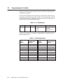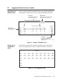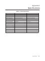
1
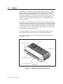
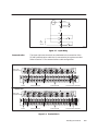
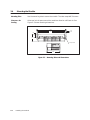
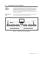
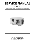
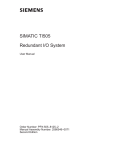
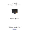
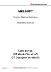
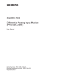
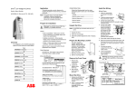
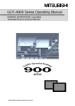
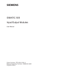
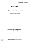
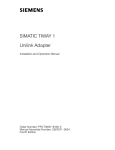
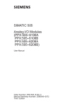
SIMATIC TI505 Smart Slice Discrete I/O Module User Manual Order Number: PPX:505–8105–2 Manual Assembly Number: 2586546–0063 Second Edition Copyright 1993 by Siemens Industrial Automation, Inc. All Rights Reserved — Printed in USA Reproduction, transmission or use of this document or contents is not permitted without express consent of Siemens Industrial Automation, Inc. All rights, including rights created by patent grant or registration of a utility model or design, are reserved. Since Siemens Industrial Automation, Inc. does not possess full access to data concerning all of the uses and applications of customer’s products, we do not assume responsibility either for customer product design or for any infringements of patents or rights of others which may result from our assistance. 01/21/92 Technical data is subject to change. We check the contents of every manual for accuracy at the time it is approved for printing; however, there may be undetected errors. Any errors found will be corrected in subsequent editions. Any suggestions for improvement are welcomed. MANUAL PUBLICATION HISTORY SIMATIC TI505 Smart Slice Discrete I/O Module User Manual Order Manual Number: PPX:505–8105–2 Refer to this history in all correspondence and/or discussion about this manual. Event Date Description Original Issue Second Edition 02/93 08/93 Original Issue (2591744–0001) Second Edition (2591744–0002 LIST OF EFFECTIVE PAGES Pages Cover/Copyright History/Effective Pages iii — vii 1-1 — 1-2 2-1 — 2-7 3-1 — 3-3 4-1 — 4-3 A-1 — A-2 Registration Description Second Second Second Second Second Second Second Second Second Pages Description Contents Preface Chapter 1 1.1 Features . . . . . . . . . . . . . . . . . . . . . . . . . . . . . . . . . . . . . . . . . . . . . . . . . . . . . . . . . . . . . . . . . . . . . . . . Chapter 2 2.1 2.2 2.3 2.4 2.5 Product Overview 1-2 Installing the Module Overview of Installation . . . . . . . . . . . . . . . . . . . . . . . . . . . . . . . . . . . . . . . . . . . . . . . . . . . . . . . . . 2-2 Flow of Tasks . . . . . . . . . . . . . . . . . . . . . . . . . . . . . . . . . . . . . . . . . . . . . . . . . . . . . . . . . . . . . . . . . . . . Visual Inspection . . . . . . . . . . . . . . . . . . . . . . . . . . . . . . . . . . . . . . . . . . . . . . . . . . . . . . . . . . . . . . . . Setting the Address Switch . . . . . . . . . . . . . . . . . . . . . . . . . . . . . . . . . . . . . . . . . . . . . . . . . . . . . . 2-2 2-2 2-2 Field Wiring Guidelines . . . . . . . . . . . . . . . . . . . . . . . . . . . . . . . . . . . . . . . . . . . . . . . . . . . . . . . . . . 2-3 Avoiding Noise . . . . . . . . . . . . . . . . . . . . . . . . . . . . . . . . . . . . . . . . . . . . . . . . . . . . . . . . . . . . . . . . . 2-3 Terminal Block . . . . . . . . . . . . . . . . . . . . . . . . . . . . . . . . . . . . . . . . . . . . . . . . . . . . . . . . . . . . . . . . . . 2-4 Power . . . . . . . . . . . . . . . . . . . . . . . . . . . . . . . . . . . . . . . . . . . . . . . . . . . . . . . . . . . . . . . . . . . . . . . . . . Outputs . . . . . . . . . . . . . . . . . . . . . . . . . . . . . . . . . . . . . . . . . . . . . . . . . . . . . . . . . . . . . . . . . . . . . . . . Inputs . . . . . . . . . . . . . . . . . . . . . . . . . . . . . . . . . . . . . . . . . . . . . . . . . . . . . . . . . . . . . . . . . . . . . . . . . . Communication . . . . . . . . . . . . . . . . . . . . . . . . . . . . . . . . . . . . . . . . . . . . . . . . . . . . . . . . . . . . . . . . 2-4 2-4 2-4 2-5 Mounting the Module . . . . . . . . . . . . . . . . . . . . . . . . . . . . . . . . . . . . . . . . . . . . . . . . . . . . . . . . . . . 2-6 Mounting Tabs . . . . . . . . . . . . . . . . . . . . . . . . . . . . . . . . . . . . . . . . . . . . . . . . . . . . . . . . . . . . . . . . . . Clearance for Cooling . . . . . . . . . . . . . . . . . . . . . . . . . . . . . . . . . . . . . . . . . . . . . . . . . . . . . . . . . . 2-6 2-6 Communications Cable Configuration . . . . . . . . . . . . . . . . . . . . . . . . . . . . . . . . . . . . . . . . . . . 2-7 Installing Terminating Resistors . . . . . . . . . . . . . . . . . . . . . . . . . . . . . . . . . . . . . . . . . . . . . . . . . . . Connecting the Trunk . . . . . . . . . . . . . . . . . . . . . . . . . . . . . . . . . . . . . . . . . . . . . . . . . . . . . . . . . . . 2-7 2-7 Chapter 3 Programming and Assigning I/O Points 3.1 Programming the Controller . . . . . . . . . . . . . . . . . . . . . . . . . . . . . . . . . . . . . . . . . . . . . . . . . . . . . 3-2 3.2 Logging the Module into the Controller . . . . . . . . . . . . . . . . . . . . . . . . . . . . . . . . . . . . . . . . . . . 3-3 Selecting the I/O Definition Chart . . . . . . . . . . . . . . . . . . . . . . . . . . . . . . . . . . . . . . . . . . . . . . . . Viewing the I/O Configuration Chart . . . . . . . . . . . . . . . . . . . . . . . . . . . . . . . . . . . . . . . . . . . . . 3-3 3-3 Chapter 4 4.1 4.2 Troubleshooting Status Indicators . . . . . . . . . . . . . . . . . . . . . . . . . . . . . . . . . . . . . . . . . . . . . . . . . . . . . . . . . . . . . . . . 4-2 Module Status Indicators . . . . . . . . . . . . . . . . . . . . . . . . . . . . . . . . . . . . . . . . . . . . . . . . . . . . . . . . I/O Status Indicators . . . . . . . . . . . . . . . . . . . . . . . . . . . . . . . . . . . . . . . . . . . . . . . . . . . . . . . . . . . . 4-2 4-2 Replacing the Fuse . . . . . . . . . . . . . . . . . . . . . . . . . . . . . . . . . . . . . . . . . . . . . . . . . . . . . . . . . . . . . 4-3 Appendix A Specifications . . . . . . . . . . . . . . . . . . . . . . . . . . . . . . . . . . . . . . . . . Contents A-1 iii List of Figures 1-1 SIMATIC TI505 Smart Slice I/O Module . . . . . . . . . . . . . . . . . . . . . . . . . . . . . . . . . . . . . . . . . . . . 1-2 2-1 2-2 2-3 2-4 2-5 2-6 Flowchart of Installation . . . . . . . . . . . . . . . . . . . . . . . . . . . . . . . . . . . . . . . . . . . . . . . . . . . . . . . . . Output Wiring . . . . . . . . . . . . . . . . . . . . . . . . . . . . . . . . . . . . . . . . . . . . . . . . . . . . . . . . . . . . . . . . . . Input Wiring . . . . . . . . . . . . . . . . . . . . . . . . . . . . . . . . . . . . . . . . . . . . . . . . . . . . . . . . . . . . . . . . . . . . Terminal Block . . . . . . . . . . . . . . . . . . . . . . . . . . . . . . . . . . . . . . . . . . . . . . . . . . . . . . . . . . . . . . . . . . Mounting Tabs and Dimensions . . . . . . . . . . . . . . . . . . . . . . . . . . . . . . . . . . . . . . . . . . . . . . . . . . Communications Cable Configuration . . . . . . . . . . . . . . . . . . . . . . . . . . . . . . . . . . . . . . . . . . . 2-2 2-4 2-5 2-5 2-6 2-7 3-1 3-2 Sample I/O Definition Chart . . . . . . . . . . . . . . . . . . . . . . . . . . . . . . . . . . . . . . . . . . . . . . . . . . . . . I/O Configuration Chart . . . . . . . . . . . . . . . . . . . . . . . . . . . . . . . . . . . . . . . . . . . . . . . . . . . . . . . . . 3-3 3-3 A-1 Derating for Both Models . . . . . . . . . . . . . . . . . . . . . . . . . . . . . . . . . . . . . . . . . . . . . . . . . . . . . . . . A-2 iv Contents List of Tables 3-1 3-2 I/O Configuration . . . . . . . . . . . . . . . . . . . . . . . . . . . . . . . . . . . . . . . . . . . . . . . . . . . . . . . . . . . . . . . Addressing Example . . . . . . . . . . . . . . . . . . . . . . . . . . . . . . . . . . . . . . . . . . . . . . . . . . . . . . . . . . . . 3-2 3-2 A-1 A-2 Electrical Specifications . . . . . . . . . . . . . . . . . . . . . . . . . . . . . . . . . . . . . . . . . . . . . . . . . . . . . . . . . Environmental Specifications . . . . . . . . . . . . . . . . . . . . . . . . . . . . . . . . . . . . . . . . . . . . . . . . . . . . A-1 A-2 Contents v Preface This manual contains instructions for installing, wiring, and operating the SIMATIC TI505 Smart Slice Discrete Input/Output (I/O) Module. The module operates with either the SIMATIC TI560T/TI565T or the SIMATIC TI545 Programmable Controller. References Agency Approvals Refer to the following manuals for instructions on installing, programming, and troubleshooting your Series 505 equipment. • SIMATIC TI545 System Manual (PPX:545–8101–x) • SIMATIC TI560T/TI565T System Manual (PPX:560/565–8105–x) • SIMATIC TI505/TI500 Programming Reference Manual (PPX:505–8104–x) • SIMATIC TI505 TISOFT User Manual (PPX:TS505–8101–x) The Series 505 Smart Slice Discrete I/O module meets the standards of the following regulatory agencies. • Underwriters Laboratories: UL Listed (Industrial Control Equipment) • Canadian Standards Association: CSA Certified (Process Control Equipment) • Factory Mutual Approved: Class I, Div 2 Hazardous Locations Series 505 products have been developed with consideration of the draft standard of the International Electrotechnical Commission Committee proposed standard (IEC-65A/WG6) for programmable controllers. Contact Siemens Industrial Automation, Inc., for a listing of the standards to which Series 505 complies. Telephoning for Assistance If you need information that is not included in this manual, or if you have problems using the SIMATIC TI505 Smart Slice, contact your Siemens Industrial Automation, Inc. distributor or sales office. If you need assistance in contacting your U.S. sales office, call 1–800–964–4114. Preface vii Chapter 1 Product Overview 1.1 Features . . . . . . . . . . . . . . . . . . . . . . . . . . . . . . . . . . . . . . . . . . . . . . . . . . . . . . . . . . . . . . . . . . . . . . . . Product Overview 1-2 1-1 1.1 Features The SIMATIC TI505 Smart Slice I/O module (shown in Figure 1-1) allows access to input and output points that are not located near a TI500/TI505 base. The module attaches directly to the RS–485 remote I/O link and emulates a remote base. The module has ten inputs and six outputs. Power is derived from field excitation voltage. The PPX:505–9201 operates on 24 VDC; the PPX:505–9202 operates on 110 VAC. See Appendix A for the voltages supported. Two terminals are provided on a removable connector for each I/O point to eliminate the need for a terminal strip. The sinking inputs have a high-side (line or positive) terminal and the sourcing outputs have a low-side (neutral or negative) terminal. A single replaceable fuse protects all the inputs and outputs. Status indicators are provided for each I/O point, the fuse, remote I/O communications, and module power. The module appears to the controller as a high-density, 16-point input, 8-point output module. See Chapter 3 for a configuration example. The module is compatible with TI545 and TI560/TI565 Programmable Controllers (PLCs). Fuse Module status indicators Mounting tabs Input/output status indicators Terminal block and cover Address switch a000626 Figure 1-1 SIMATIC TI505 Smart Slice I/O Module 1-2 Product Overview Chapter 2 Installing the Module 2.1 2.2 2.3 2.4 2.5 Overview of Installation . . . . . . . . . . . . . . . . . . . . . . . . . . . . . . . . . . . . . . . . . . . . . . . . . . . . . . . . . 2-2 Flow of Tasks . . . . . . . . . . . . . . . . . . . . . . . . . . . . . . . . . . . . . . . . . . . . . . . . . . . . . . . . . . . . . . . . . . . . Visual Inspection . . . . . . . . . . . . . . . . . . . . . . . . . . . . . . . . . . . . . . . . . . . . . . . . . . . . . . . . . . . . . . . . Setting the Address Switch . . . . . . . . . . . . . . . . . . . . . . . . . . . . . . . . . . . . . . . . . . . . . . . . . . . . . . 2-2 2-2 2-2 Field Wiring Guidelines . . . . . . . . . . . . . . . . . . . . . . . . . . . . . . . . . . . . . . . . . . . . . . . . . . . . . . . . . . 2-3 Avoiding Noise . . . . . . . . . . . . . . . . . . . . . . . . . . . . . . . . . . . . . . . . . . . . . . . . . . . . . . . . . . . . . . . . . 2-3 Terminal Block . . . . . . . . . . . . . . . . . . . . . . . . . . . . . . . . . . . . . . . . . . . . . . . . . . . . . . . . . . . . . . . . . . 2-4 Power . . . . . . . . . . . . . . . . . . . . . . . . . . . . . . . . . . . . . . . . . . . . . . . . . . . . . . . . . . . . . . . . . . . . . . . . . . Outputs . . . . . . . . . . . . . . . . . . . . . . . . . . . . . . . . . . . . . . . . . . . . . . . . . . . . . . . . . . . . . . . . . . . . . . . . Inputs . . . . . . . . . . . . . . . . . . . . . . . . . . . . . . . . . . . . . . . . . . . . . . . . . . . . . . . . . . . . . . . . . . . . . . . . . . Communication . . . . . . . . . . . . . . . . . . . . . . . . . . . . . . . . . . . . . . . . . . . . . . . . . . . . . . . . . . . . . . . . 2-4 2-4 2-4 2-5 Mounting the Module . . . . . . . . . . . . . . . . . . . . . . . . . . . . . . . . . . . . . . . . . . . . . . . . . . . . . . . . . . . 2-6 Mounting Tabs . . . . . . . . . . . . . . . . . . . . . . . . . . . . . . . . . . . . . . . . . . . . . . . . . . . . . . . . . . . . . . . . . . Clearance for Cooling . . . . . . . . . . . . . . . . . . . . . . . . . . . . . . . . . . . . . . . . . . . . . . . . . . . . . . . . . . 2-6 2-6 Communications Cable Configuration . . . . . . . . . . . . . . . . . . . . . . . . . . . . . . . . . . . . . . . . . . . 2-7 Installing Terminating Resistors . . . . . . . . . . . . . . . . . . . . . . . . . . . . . . . . . . . . . . . . . . . . . . . . . . . Connecting the Trunk . . . . . . . . . . . . . . . . . . . . . . . . . . . . . . . . . . . . . . . . . . . . . . . . . . . . . . . . . . . 2-7 2-7 Installing the Module 2-1 2.1 Overview of Installation Flow of Tasks Figure 2-1 shows the organization of the tasks described in this chapter. Set address switch Secure module to panel Wire terminal block Power up Figure 2-1 Flowchart of Installation Visual Inspection If there is any visible damage to the module, contact your Siemens Industrial Automation, Inc. distributor or sales office. If you need assistance in contacting your U.S. sales office, call 1–800–964–4114. Setting the Address Switch Use the address switch to assign the address number to the unit for system identification. Each unit must have a unique address number. The switch is labeled 0 through F, hexadecimal. Therefore, a switch number of 5 equals address 5, and a switch number of E equals address 14. An address of 0 is valid only with the TI560/TI565 controller. WARNING To minimize the potential risk of injury to personnel or damage to the system, do not change the unit address switch while the system is operating. Unpredictable behavior may result. ! 2-2 Installing the Module 2.2 Field Wiring Guidelines ! WARNING To minimize the potential risk of injury to personnel or damage to the system, use supply wires suitable for at least 75° C. Signal wiring connected to this module must be rated at least 300 V. ! ATTENTION Employer des fils d’alimentation pour au moins 75° C. Le cablage de signalisation raccorde dans cette boite doit convenir pour une tension nominale d’au moins 300 V. Avoiding Noise To avoid noise problems, follow these guidelines when you install the module. • Use the shortest possible wires. • Avoid placing signal wires parallel to high-energy wires. If the two must meet, cross them at right angles. • Avoid bending the wire into sharp angles. • Use wireways for wire routing. • When you use shielded wires, ground them only at the source end for better noise immunity. • Place wires so that they do not interfere with existing wiring. Installing the Module 2-3 2.3 Terminal Block The module is equipped with a 38-position, removable terminal block. All field wiring is connected to this terminal block. The terminal block accepts wires between 14 and 22 AWG. The terminal block is covered with a hinged shroud, which has a terminal identification label on the inside. The terminal block is divided into four different sections: power, outputs, inputs, and communication. See Figure 2-4. ! WARNING To minimize the potential risk of injury to personnel or damage to the system, ensure that all user-supplied wiring is de-energized before attempting to connect to terminal block. Power The three leftmost terminals are dedicated to user-supplied power and ground. See Appendix A for the voltages supported. Outputs The output load terminals are labeled 1 through 6, while the output return terminals are labeled YC. All the output return terminals are low-side (neutral or negative) terminals, and are connected together inside the module as shown in Figure 2-2. Internal External L Line + N Neutral – YC Load 1 YC Y Common 2 Load I003040 Figure 2-2 Output Wiring Inputs 2-4 The input signal terminals are labeled 1 through 10, while the input source terminals are labeled XC. All the input source terminals are high-side (line or positive) terminals, and are connected together inside the module as shown in Figure 2-3. Installing the Module Internal External L Line + N Neutral – XC X1 To input circuit XC X2 I003041 Figure 2-3 Input Wiring Communication PPX:505–9201 The three right-most terminals are dedicated to the connection of the RS–485 communication cable that is connected to the system controller. Refer to Section 2.5 for communications cable configuration. LED status window Identification label Label under hinged shroud Power PPX:505–9202 Output terminals LED status window Input terminals Communication terminals Identification label Label under hinged shroud Power Output terminals Input terminals Communication terminals a000627 Figure 2-4 Terminal Block Installing the Module 2-5 2.4 Mounting the Module Mounting Tabs Use the mounting tabs to secure the module. The tabs accept #8–32 screws. Clearance for Cooling Allow one inch of space around the module to allow for sufficient air flow. Figure 2-5 shows mounting dimensions. 8.80 1.99 8.37 8.00 0.21 0.18 1.99 Accepts #8-32 4.00 a000628 Figure 2-5 Mounting Tabs and Dimensions 2-6 Installing the Module 2.5 Communications Cable Configuration Installing Terminating Resistors Install a terminating resistor across the DATA+ and DATA– terminals. If your application involves a series of Smart Slices, install a terminating resistor on the Smart Slice on the end. If your application uses only one Smart Slice, install a terminating resistor on that one. Refer to your controller user manual for cable installation guidelines and for the resistor values for your cable type. Connecting the Trunk You must connect the trunk directly to the Smart Slice. Do not use drop lines to connect to the Smart Slice. Refer to Figure 2-6. TI545 or TI560/TI565 Terminating resistor Maximum trunk length Terminating resistor Maximum trunk length T Smart Slice Smart Slice Smart Slice Smart Slice Smart Slice Smart Slice Terminal block Total trunk length I002749 Figure 2-6 Communications Cable Configuration Installing the Module 2-7 Chapter 3 Programming and Assigning I/O Points 3.1 Programming the Controller . . . . . . . . . . . . . . . . . . . . . . . . . . . . . . . . . . . . . . . . . . . . . . . . . . . . . 3-2 3.2 Logging the Module into the Controller . . . . . . . . . . . . . . . . . . . . . . . . . . . . . . . . . . . . . . . . . . . 3-3 Selecting the I/O Definition Chart . . . . . . . . . . . . . . . . . . . . . . . . . . . . . . . . . . . . . . . . . . . . . . . . Viewing the I/O Configuration Chart . . . . . . . . . . . . . . . . . . . . . . . . . . . . . . . . . . . . . . . . . . . . . 3-3 3-3 Programming and Assigning I/O Points 3-1 3.1 Programming the Controller Refer to the program design manual for your controller for specific details on designing a program. The Smart Slice appears to the controller as a high-density, 16-point input and 8-point output module as shown in Table 3-1. Since the Smart Slice has 10 inputs and 6 outputs, the balance of 6 input points and 2 output points are not used in the I/O configuration table. Table 3-1 I/O Configuration Density Inputs Outputs I/O Points Values High 16 8 X1–10 X11–16 Y17–22 Y23–24 Input points 1–10 Not used Output points 1–6 Not used Table 3-2 shows how the I/O address is determined for a module with the starting address of 81. Table 3-2 Addressing Example Program Input Address 3-2 Corresponding Module Input Address Program Output Address Corresponding Module Output Address X81 X1 Y97 Y17 X82 X2 Y98 Y18 X83 X3 Y99 Y19 X84 X4 Y100 Y20 X85 X5 Y101 Y21 X86 X6 Y102 Y22 X87 X7 X88 X8 X89 X9 X90 X10 Programming and Assigning I/O Points 3.2 Logging the Module into the Controller Selecting the I/O Definition Chart Figure 3-1 shows a sample I/O definition chart with a module designated with address 01. Refer to your TISOFT manual for detailed instructions. I/O Address The module is logged in as 16 inputs and 8 outputs. I/O MODULE DEFINITION FOR : I/O Slot Number Smart Slice is always shown as slot 1. Slot Base Number Displays the unique base address assigned to this Smart Slice. CHANNEL 1 BASE xx Number of Bit and Word I/O WX Special Address X Y WY Function 1 ..... 0001 ..... 16 .. 08 .. 00 .. 00 ....... No 2 ..... 0000 ..... 00 .. 00 .. 00 .. 00 ....... No 3 ..... 0000 ..... 00 .. 00 .. 00 .. 00 ....... No 4 ..... 0000 ..... 00 .. 00 .. 00 .. 00 ....... No SF Module Smart Slice is not an SF Module. The default for this definition is no. I000725 Figure 3-1 Sample I/O Definition Chart Viewing the I/O Configuration Chart Use SHOW or a similar menu selection to display the I/O Configuration Chart. The configuration in Figure 3-1 appears as shown in Figure 3-2. I/O CONFIGURATION CHART FOR CHANNEL . . . 1 BASE . . . . . 01 I/O POINTS SLOT 1 1 X0001 2 X0002 3 X0003 4 X0004 5 X0005 6 X0006 7 X0007 8 X0008 SLOT 1 9 X0009 10 X0010 11 X0011 12 X0012 13 X0013 14 X0014 15 X0015 16 X0016 SLOT 1 17 Y0017 18 Y0018 19 Y0019 20 Y0020 21 Y0021 22 Y0022 23 Y0023 24 Y0024 SLOT 2 SLOT 3 SLOT 4 Figure 3-2 I/O Configuration Chart Programming and Assigning I/O Points 3-3 Chapter 4 Troubleshooting 4.1 4.2 Status Indicators . . . . . . . . . . . . . . . . . . . . . . . . . . . . . . . . . . . . . . . . . . . . . . . . . . . . . . . . . . . . . . . . 4-2 Module Status Indicators . . . . . . . . . . . . . . . . . . . . . . . . . . . . . . . . . . . . . . . . . . . . . . . . . . . . . . . . I/O Status Indicators . . . . . . . . . . . . . . . . . . . . . . . . . . . . . . . . . . . . . . . . . . . . . . . . . . . . . . . . . . . . 4-2 4-2 Replacing the Fuse . . . . . . . . . . . . . . . . . . . . . . . . . . . . . . . . . . . . . . . . . . . . . . . . . . . . . . . . . . . . . 4-3 Troubleshooting 4-1 4.1 Status Indicators Module Status Indicators The MOD GOOD indicator turns on when the module is receiving the correct power. The COM OK indicator has three modes of operation. When the LED is not on, this indicates that the communication cable is not installed properly or that the controller is not functioning properly. When the LED is blinking, it indicates that the module is not configured properly in the controller. When the LED remains on, this indicates that communication is occurring and that the unit is configured properly. The FUSE indicator turns on when the fuse is blown. You also can determine the status of the fuses by using RLL to check the module fail bit in the controller. (See your SIMATIC TI505 Programmable Controller manual.) I/O Status Indicators There are six output status LEDs. The output status indicators show the status of the output points. When an output point is on, the corresponding LED lights. The output indicators show the status from the logic (controller) side, not the field side. There are ten input status LEDs. The input status indicators show the status of the input points. When an input point is on, the corresponding LED lights. The input indicators show status from the field side, not the logic (controller) side. 4-2 Troubleshooting 4.2 ! Replacing the Fuse WARNING To minimize the potential risk of injury to personnel or damage to the system, ensure that all user-supplied power is disconnected from the module before attempting the replace the fuse. The fuse is located in the rear of the module, through an access opening. Use an 8 A, 250 VAC 5 × 20 mm normal-blow replacement fuse. Replace the fuse only when the FUSE indicator is on. Troubleshooting 4-3 Appendix A Specifications Table A-1 Electrical Specifications Specification PPX:505–9201 PPX:505–9202 Description 24 VDC, 10 inputs/6 outputs 110 VAC, 10 inputs/6 outputs Rated voltage 20–30 VDC 90–132 VAC, 47–63 Hz Input type Sinking, high-side common Sinking, high-side common Input on voltage range 15 VDC min, 30 VDC max 79 VAC min, 132 VAC max Input on current range 2.0 mA min, 6.0 mA max 4.0 mA min, 13.0 mA max Input off voltage range 0.0 VDC min, 5.0 VDC max 0.0 VAC min, 20.0 VAC max Input off current range 0.5 mA max 1.0 mA max Input delay time 2 ms max 6 ms min, 40 ms max Output type Sourcing, low-side common Sourcing, low-side common Output current 0.5 A max at 60°C, 1.0 A max at 40°C 0.5 A max at 60°C, 1.0 A max at 40°C Output temporary overload 3.0 A for 1 ms 5.0 A rms for 2 cycles Output DV/DT — 300 V/µs Output on voltage drop 1.0 VDC 1.4 Vrms at 1.0 A Output off leakage current 0.02 mA max 2.0 mA max Output delay time 4.0 ms on-to-off, 2.0 ms off-to-on 11 ms on-to-off, 2.0 ms off-to-on Specifications A-1 Table A-2 Environmental Specifications Wire gauge 14–22 AWG Spade lug for use with connector Amp part number 321462 Ring lug for use with connector Amp part number 327891 Operating temperature 0 to 60°C (32 to 140°F) Storage temperature –40 to +70°C (–40 to 158°F) Relative humidity 5% to 95% noncondensing Pollution degree 2, IEC 664, 664 A Vibration Sinusoidal IEC 68-2-6, Test Fc 0.15 mm peak-to-peak, 10–57 Hz; 1.0 g, 57–150 Hz Random IEC 68-2-34, Test Fdc, equivalent to NAVMAT P–9492 0.04 g2/Hz, 80–350 Hz Electrostatic discharge IEC 801, Part 2, Level 4, (15 kV) Shock IEC 68-2-27; Test Ea Noise immunity, conducted IEC 801, Part 4, Level 3 Noise immunity on user power lines MIL STD 461B, CS01, CS02, CS06, IEC 255-4, IEEE 472 Noise immunity, radiated IEC 801, Part 3, Level 3, MIL STD 461B, RS01, RS02, RS03 Corrosion protection All parts of corrosion-resistant material or plated or painted as corrosion protection Load current per output in amps 1.25 One point / all points on 1.00 0.75 0.50 0.25 0 5 10 15 20 25 30 35 40 45 50 55 60 65 70 Ambient temperature in degrees Celcius I002750 Figure A-1 Derating for Both Models A-2 Specifications " #!! " !" ! #!!" " $"#! $## ! #!!" &" "#!$#" ! !# " !"#! #!! !%!#!" !#!" " !"#! #!! #!" ""# Customer Registration We would like to know what you think about our user manuals so that we can serve you better. How would you rate the quality of our manuals? Excellent Good Fair Poor Accuracy Organization Clarity Completeness Overall design Size Index Would you be interested in giving us more detailed comments about our manuals? Yes! Please send me a questionnaire. No. Thanks anyway. Your Name: Title: Telephone Number: ( ) Company Name: Company Address: Manual Name: SIMATIC TI505 Smart Slice Discrete I/O Module User Manual Manual Assembly Number: 2586546-0063 Order Number: PPX:505–8105–2 Edition: Date: Second 08/93 FOLD NO POSTAGE NECESSARY IF MAILED IN THE UNITED STATES BUSINESS REPLY MAIL FIRST CLASS PERMIT NO.3 JOHNSON CITY, TN POSTAGE WILL BE PAID BY ADDRESSEE ATTN: Technical Communications M/S 3519 SIEMENS INDUSTRIAL AUTOMATION INC. 3000 BILL GARLAND RD P O BOX 1255 JOHNSON CITY TN 37605–1255 FOLD