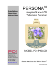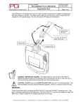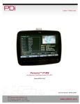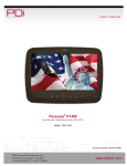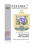
1
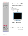
Installation
Operating
Instructions
PERSONA
10
Hospital-Grade LCD
Digital Television Receiver
MODEL PDI-P10LCD-C
Communication
Systems, Inc.
40 Greenwood Lane
Springboro, Ohio 45066
PH: 937-743-6010
FX: 937-743-5664
http://www.pdiarm.com
Better Solutions Are Within Reach®
DOCUMENT NUMBER PD196-120R1
PDI-P10LCD-C USER MANUAL
Document Number PD196-120R1
2
Graphical Symbols
This lightning flash with arrowhead symbol, within an equilateral is intended to
alert the user of the presence of uninsulated “dangerous voltage” within the
product’s enclosure that may be of sufficient magnitude to constitute a risk of
electric shock to persons.
The exclamation point within an equilateral triangle is intended to alert the user of
the presence of important operating and maintenance (servicing) instructions in
the literature accompanying the appliance.
CAUTION
RISK OF ELECTRIC SHOCK,
DO NOT OPEN
CAUTION: TO REDUCE THE RISK OF ELECTRICAL SHOCK, DO
NOT REMOVE COVER, NO USER SERVICEABLE PARTS INSIDE.
REFER SERVICING TO QUALIFIED SERVICE PERSONNEL.
Important Safety Instructions
PLEASE READ AND KEEP THESE INSTRUCTIONS. OBSERVE ALL WARNINGS AND
FOLLOW ALL INSTRUCTIONS CONTAINED IN THESE SAFETY INSTRUCTIONS AND THOSE
ON YOUR TELEVISION. RETAIN THESE INSTRUCTIONS FOR FUTURE USE.
Electrical energy can perform many useful functions. This unit has been engineered and
manufactured to assure your personal safety. However, improper use can result in potential
electrical shock or fire hazards. In order not to defeat the safe-guards incorporated on this
receiver, observe the following basic rules for its installation, use and servicing. Your television is
fully transistorized and does not contain any user serviceable components. Removal of the
cabinet cover may expose you to dangerous voltages. Refer all servicing to qualified service
personnel.
1.
2.
3.
4.
5.
6.
7.
8.
9.
10.
Read these instructions.
Keep these instructions.
Heed all warnings.
Follow all instructions.
Do not use this apparatus near water.
Clean only with dry cloth.
Do no block any ventilation openings. Install in
accordance with the manufacturer’s instructions.
Do not install near any heat source such as radiators,
heat registers, stove, or other apparatus (including
amplifiers) that produce heat.
Do not defeat the safety purpose of the polarized or
grounding-type plug. A polarized plug has two blades
with one wider than the other. A grounding type plug
has two blades and a third grounding prong. The
wide blade or the third prong are provided for your
safety. If the provided plug does not fit into your
outlet, consult an electrician for replacement of the
obsolete outlet.
Protect the power cord from being walked on or
pinched particularly at plugs, convenience
receptacles, and the point where they exit from the
apparatus.
PDI Communication Systems, Inc.
Phone 937-743-6010
11.
12.
13.
14.
Only use attachments/accessories specified by the
manufacturer.
Use only with the cart, stand,
tripod, bracket or table
specified by the manufacturer,
or sold with the apparatus.
When a cart is used, use
caution when moving the
cart/apparatus combination to
avoid injury from tip-over.
Unplug this apparatus during lightning storms or when
unused for long period of time.
Refer all servicing to qualified service personnel.
Servicing is required when the apparatus has been
damaged in any way, such as power-supply cord or
plug is damaged, liquid has been spilled or objects
have fallen into the apparatus, the apparatus has
been exposed to rain or moisture, does not operate
normally, or has been dropped.
40 Greenwood Lane
Fax 937-743-5664
Springboro, Ohio 45066
email: [email protected]
PDI-P10LCD-C USER MANUAL
Document Number PD196-120R1
3
WARNING – To reduce the risk of fire or electric shock, do not expose this
apparatus to rain or moisture.
WARNING – OXYGEN ENVIRONMENT: Do not use in any oxygen tent or
oxygen chamber. Such use may cause a fire hazard.
Apparatus shall not be exposed to dripping or splashing and no objects filled with liquids, such as
vases, shall be placed on the apparatus
Copyright, Disclaimer, and Trademarks
COPYRIGHT
PDI Communication Systems, Inc. claims proprietary right to the material disclosed in this user
manual. This manual is issued for user information only and may not be used to manufacture
anything shown herein. Copyright © 2000 - 2007 by PDI Communication Systems, Inc. All
rights reserved.
Manufactured under license from Dolby Laboratories. “Dolby” and the double-D symbol are
trademarks of Dolby Laboratories.
DISCLAIMER
The author and publisher have used their best efforts in preparing this manual. PDI
Communication Systems, Inc. make no representation or warranties with respect to the accuracy
or completeness of the contents of this manual and specifically disclaim any implied warranties or
merchantability or fitness for any particular purpose and shall in no event be liable for any loss of
profit or any other damages. The information contained herein is believed accurate, but is not
warranted, and is subject to change without notice or obligation.
TRADEMARKS
All brand names and product names used in this manual are trademarks, registered trademarks,
or trade names of their respective holder. PDI and Better Solutions Are Within Reach are
registered trademarks of PDI Communication Systems, Inc., Springboro, Ohio.
Regulatory Information
FCC
This equipment has been tested and found to comply with the limits for a Class B digital device,
pursuant to part 15 of the FCC Rules. These limits are designed to provide reasonable protection
against harmful interference when the equipment is operated in a residential or commercial
installation. If this equipment does cause harmful interference to radio or television reception,
which can be determined by turning the equipment off and on, the user is encouraged to try to
correct the interference by one of more of the following measures:
• Reorient or relocate the receiving antenna.
• Increase the separation between the equipment and receiver.
• Connect the equipment into an outlet on a circuit different from that to which the receiver
is connected.
• Consult the dealer or an experienced radio/TV technician for help.
Underwriters Laboratories
The model PDI-P10LCD-C Hospital Grade LCD TV is a specialized LCD
television and should be installed to National Electrical Code specifications.
This device is safety tested and listed by the Underwriters Laboratories as a
product suitable for use in health care facilities in both the United States
and Canada.
PDI Communication Systems, Inc.
Phone 937-743-6010
40 Greenwood Lane
Fax 937-743-5664
Springboro, Ohio 45066
email: [email protected]
PDI-P10LCD-C USER MANUAL
Document Number PD196-120R1
4
Installation Precautions
1. Any changes or modifications in construction of this television, which
are not expressly approved by the party responsible for compliance,
could void the user’s authority to operate the equipment.
2. Use only a power source from a CSA Certified / UL Approved Class 2
Power Supply suitable for use in a Health Care Facility. This TV will
operate on either DC or AC voltage, range 18 to 32 volts.
3. THIS INSTALLATION SHOULD BE MADE BY A QUALIFIED
SERVICE PERSON AND SHOULD CONFORM TO ALL LOCAL
CODES. READ AND FOLLOW THE SAFETY INSTRUCTIONS
BEFORE ATTEMPTING THIS INSTALLATION.
4. NOTE TO CATV INSTALLER: This reminder is provided to call the
CATV system installer’s attention to Article 820-40 of the NEC that
provides guidelines for proper grounding and, in particular, specifies
that the cable ground shall be connected to the grounding system of
the building, as close to the point of cable entry as practical.
USE RECOMMENDED
COAX. USE OF ANY
OTHER CABLE
NUMBER IS NOT
RECOMMENDED.
5. COAX CABLE SPECIFICATION: When using a central power
supply, cable selection is crucial. Due to long coax cable runs
encountered in hospital installations, coax cable employing a solid
copper center conductor and copper shield is required. Cable run
lengths MUST NOT exceed 150 feet. Required coaxial cable
numbers include Alpha 9804C (non-plenum), Belden 9248 (nonPlenum), West Penn 806 (non-Plenum), or West Penn 25806
(Plenum), which have been tested with coax-powered televisions.
6. CLEANING: Clean the exterior of this television by removing dust
with a lint-free cloth. For further cleaning, use a soft cloth or paper
towel dampened with water. CAUTION: To avoid damage to the
surface of the television, do not use abrasive or chemical cleaning
agents.
7. DISINFECTING: Do not immerse this TV, rather clean with a soft
damp cloth. To avoid damage to the surface of the television, test a
small portion of the TV’s cabinet with any new disinfectant to verify
that the disinfectant will not discolor or soften the enclosure.
8. WARNING: To avoid the hazards of fire or electrical shock, DO NOT
expose this television to rain or moisture.
9. WARNING OXYGEN ENVIRONMENT: Do not use in any oxygen
tent or oxygen chamber. Such use may cause a fire hazard.
PDI Communication Systems, Inc.
Phone 937-743-6010
40 Greenwood Lane
Fax 937-743-5664
Springboro, Ohio 45066
email: [email protected]
PDI-P10LCD-C USER MANUAL
Document Number PD196-120R1
5
Contents
Graphical Symbols…………………………………………………………………….. 2
Important Safety Instructions…………………………………………………………. 2
Copyright, Disclaimer, and Trademarks…………………………………………….. 3
Regulatory Information………………………………………………………………... 3
Installation Precautions……………………………………………………………….. 4
Contents………………………………………………………………………………… 5
About the PERSONA 10………………………………………………………………. 6
Installing TV on Suspension Arm…………………………………………………….. 7
Control Panel…………………………………………………………………………… 9
Earphone Operation………………………………………………………………….. 10
Remote Control……………………………………………………………………….. 10
Service Levels (Tiers)………………………………………………………………… 11
Channel Setup………………………………………………………………………… 12
Add / Delete Analog Channels………………………………………………………. 12
Enable/Disable Digital Channel……………………………………………………… 13
Clear Service Level…………………………………………………………………… 13
Copy Service Level…………………………………………………………………… 14
Power-on Channel and Speaker……………………………………………………. 14
Volume Limiter………………………………………………………………………… 15
Caption Text Modes……………………………………………………………………15
Time Zone……………………………………………………………………………… 16
Power On ARC………………………………………………………………………… 16
Language……………………………………………………………………………….. 17
Picture…………………………………………………………………………………… 17
FAQ – Frequently Asked Questions…………………………………………………. 18
APPENDIX A – Installation on Other PDI-508C Arms………………………………19
Model PDI-P10LCD-C Limited Warranty……………………………………………. 21
PDI Communication Systems, Inc.
Phone 937-743-6010
40 Greenwood Lane
Fax 937-743-5664
Springboro, Ohio 45066
email: [email protected]
PDI-P10LCD-C USER MANUAL
Document Number PD196-120R1
6
About the PERSONA 10
This television is specifically designed for entertainment purposes and for use in a
hospital, a nursing home, a medical-care center, or a similar health-care center in
which installation is limited to a non-hazardous area in accordance with the
National Electrical Code, ANSI/NFPA 70.
This user’s guide has been designed for both the TV installer and TV Rental
Representatives. It identifies the features of the PERSONA 10 and describes how
to program the TV using an infrared (IR) remote control.
Programming is the process of selecting from among the many features of the
PERSONA 10 television. It is also the process of adding and removing channels
from the three service levels this TV provides.
Please read through this guide carefully, with a PERSONA 10 TV in front of you, as
you begin the process of learning how to program these televisions. Also keep the
guide handy, so you can refer to it, for future programming changes. The
information in this guide describes each of the main SETUP MENU items:
Service Levels
Channel Setup (Programming)
Features
Picture Adjustment
PDI Communication Systems, Inc.
Phone 937-743-6010
40 Greenwood Lane
Fax 937-743-5664
Springboro, Ohio 45066
email: [email protected]
PDI-P10LCD-C USER MANUAL
Document Number PD196-120R1
7
Installing TV on Suspension Arm
The PERSONA 10 is designed to mount on a wall mounted suspension arm
capable of supporting a television weighing 7 pounds. The single coaxial cable on
top of the unit is used to supply both low voltage AC or DC power (range 18 to 32
volts) and the RF signal to the television.
Safety Brake
Pin Hole
3/4“ Socket Head
Cap Screw
Swivel Cap
Retainer Plate
DANGER: ARM RECOIL HAZARD The safety brake pin must
remain in the SAFETY BRAKE PIN HOLE whenever the television
set is removed from the arm or when the arm is removed from the
wall bracket to prevent the arm from springing open.
CAUTION: DO NOT remove the WHITE PLASTIC CAP from the swivel assembly.
This swivel assembly is factory preassembled and adjusted. There is no need to
remove the cap.
IMPORTANT:
These instructions detail installing the PDI-P10LCD-C TV onto the PDI-508C-7
suspension arm. This arm is configured specifically for this television. The PDIP10LCD-C TV may be installed on other PDI-508C arms. Please refer to Appendix
A of this document for detailed instructions for this case.
PDI Communication Systems, Inc.
Phone 937-743-6010
40 Greenwood Lane
Fax 937-743-5664
Springboro, Ohio 45066
email: [email protected]
PDI-P10LCD-C USER MANUAL
Document Number PD196-120R1
8
INSTALLING THE PDI-P10LCD-C TO THE PDI-508C-7 SUSPENSION ARM
1. Remove and save the ¾” Socket Head Cap Screw from the plastic “H” clip.
Remove the plastic “H” clip and discard.
2. Remove the two nose cover retainer bolts. Raise the metal nose cover and
slide the television completely
into the arm’s clevis (slot). The
Brake Pin
swivel retainer plate should rest
inside the nose of the arm and
Nose Cover
the plastic swivel cap beneath
(see picture on previous page).
3. Align the retainer plate’s
mounting hole over the arm
mounting hole. Thread the ¾”
Socket Head Cap Screw through
the retainer plate and into the
arm’s nose. Tighten.
Nose Cover
Retainer Bolts
4. The coax cable in the nose of the arm should be joined with the coax cable
from the television. Wrench tighten the connection and cover by sliding the
plastic boot sections into mating position.
IMPORTANT: Finger only tightening of this cable connection will result in
reliability problems weeks or months later. Because the TV draws its power
current through this connection, eventually the finger-tightened connection will
loosen, develop resistance and prompt a service call. Wrench tighten all “F”
fitting connections!
5. Remove the safety brake pin from the parking brake hole, reattach the acorn
nut to the pin, and store the assembly inside the nose of the arm by attaching it
to the coax cable using the attached plastic clip.
6. Close the metal nose cover onto the nose. Reinstall the two nose cover
retainer bolts.
7. Attach three sets of plastic arm covers (start with long “nose cover” section):
a. Assemble supplied spring pins into
one of the arm cover halves. Pins
should be installed into one cover
side only.
Spring
Pin
b. Position the Arm Cover halves
around the arm’s nose section. Align
exposed pins with the open holes in
the second cover half.
c.
Squeeze the two halves together.
When the halves are properly
installed there should only be a thin
seam visible where the halves meet.
d. Repeat steps a, b, c for the elbow
covers and base covers.
8. Connect the coax cable at the base of the arm to the wall bracket “F” fitting.
Wrench tighten. Cycle the arm once or twice to check for free movement.
PDI Communication Systems, Inc.
Phone 937-743-6010
40 Greenwood Lane
Fax 937-743-5664
Springboro, Ohio 45066
email: [email protected]
PDI-P10LCD-C USER MANUAL
Document Number PD196-120R1
Control Panel
9
DIRECT ENTRY
KEYPAD
POWER
The easy to clean membrane control panel located on the lower front of the TV
contains 9 large easy to read buttons and a numbered “direct entry” keypad for
both channel and cursor control. The 5 lower buttons are used to turn the TV ON
or OFF, change channels and raise or lower the sound volume.
If the speaker is currently programmed as “OFF” in the current service level (see
the section following on “Power-On Channel and Speaker”), the message “Speaker
Disabled” will be displayed if either volume button is pressed while no earphone is
connected.
In addition to the Channel Up and Down buttons, the numbered “direct entry”
keypad may be used to directly enter the channel desired for viewing. If the
channel entered using this keypad is not programmed in to the current Service
Level (see sections following on “Service Levels” and “Channel Setup”), the symbol
“[X]” will be displayed in red in place of the channel number, and the channel will
not change.
The “2”, “4”,”6” and “8” buttons on the direct entry keypad are also used for cursor
positioning on televisions used in computer control applications.
The “cc” button alternately activates and deactivates program closed captioning.
Note: Not all programs offer closed captions. Pressing the button may not result in
the display of any captions.
The “mute” button will mute the TV audio. The word “MUTE” will then appear on
screen. Pressing the button again or pressing the volume up or volume down
buttons will enable the TV audio and remove the word “MUTE” from the screen.
BUTTON FUNCTION SUMMARY
POWER
Turns the TV ON or OFF.
VOLUME
Increase or decrease the TV volume.
CHANNEL
Changes the viewed channel up or down.
ENTER
Used for entering channel numbers or viewing
current channel information.
MUTE
Mutes TV audio.
CC
Activates or deactivates closed captions.
FEATURE
Allows selection of Aspect Ratio for digital
channels only.
NUMBERS
Direct channel entry.
PDI Communication Systems, Inc.
Phone 937-743-6010
40 Greenwood Lane
Fax 937-743-5664
Springboro, Ohio 45066
email: [email protected]
PDI-P10LCD-C USER MANUAL
Document Number PD196-120R1
10
Earphone Operation
PD108-005C Earphone
Inserting an earphone in the “earphone” jack hole located on the right
side of the cabinet will allow silent operation of the TV. The speaker will
be shut OFF and all program audio will be available through the
earphone. Remove the earphone to enable the internal TV speaker.
The TV only offers mono sound. Use of a stereo earphone will result in
sound from only one earphone speaker. Contact PDI for either
earphone or mono style headsets.
PD108-112 Headset
Remote Control
The PERSONA 10 requires a remote
control part number PD108-412 to
program the set. You will NOT find a
remote control packed with the
television. The remote control is an
available option and would be
shipped separate from the television.
The remote control has a limited
range to prevent dual programming of
an adjacent room TV. Stand within 3
feet from the front of the TV to use
the remote control.
PDI Communication Systems, Inc.
Phone 937-743-6010
40 Greenwood Lane
Fax 937-743-5664
Springboro, Ohio 45066
email: [email protected]
PDI-P10LCD-C USER MANUAL
Document Number PD196-120R1
11
Service Levels (Tiers)
To use this television
Please contact
TV representative
The PERSONA 10 contains four separate service levels (tiers)
allowing the hospital to offer either basic or enhanced viewing. The
current service level can be quickly determined by accessing the
SETUP MODE menu using the handheld programming remote
control. The service level can be changed to any of the 4 levels at
any time using the dedicated buttons on the attendant remote or
entering the setup menu and changing the Service Level menu items.
DISABLED is like a mechanical keylock – when in Disabled service
level, the TV can be turned OFF and ON, but cannot be used for
viewing. A standard message appears on a black screen.
SETUP MODE
Service Level :
Picture
Channel Setup
Features
Language:
Free
English
Channel ▲/▼ to select
Volume ▲/▼ to change
SETUP MODE
Service Level :
Picture
Channel Setup
Features
Language:
Basic
FREE lets patients watch hospital education and information channels
without renting the television. The channels containing programming
for no charge are typically programmed into this level of service. This
is the factory default setting for service level.
The Free level is indicated in the SETUP MODE menu screen when
“Service Level: Free”.
BASIC service typically allows additional channels beyond those
offered in the FREE level.
The Basic level is indicated in the SETUP MODE menu screen when
“Service Level: Basic”.
English
Channel ▲/▼ to select
Volume ▲/▼ to change
SETUP MODE
Service Level :
Picture
Channel Setup
Features
Language:
Premium
PREMIUM – is the highest service level with typically the most
channels available for viewing.
The premium level is indicated in the SETUP MODE menu screen
when “Service Level: Premium”.
English
Channel ▲/▼ to select
Volume ▲/▼ to change
PDI Communication Systems, Inc.
Phone 937-743-6010
40 Greenwood Lane
Fax 937-743-5664
Springboro, Ohio 45066
email: [email protected]
PDI-P10LCD-C USER MANUAL
Document Number PD196-120R1
12
Channel Setup
Signal: CATV
1. AUTOPROGRAMMING
Press the “SETUP” button on the remote control. A “SETUP
MODE” screen will appear.
Autoprogram
Clear Service Level
Add/Delete Analog Channels
Copy Service Level
Enable/Disable Digital Channel
2. Using the “CH▲” or “CH▼” buttons on the remote and select
“Channel Setup”. Press “VOL▼” or “VOL▲” to enter the
“Channel Setup” sub-menu.
Channel Setup
Channel ▲/▼ to select
Volume ▲/▼ to change
Autoprogram
Mode: Analog Only
Free:
Programmed
Basic:
Blank
Premium: Blank
Channel ▲/▼ to select
Volume ▲/▼ to change
3. Select the correct “Signal” type; either CATV, Air, CATV-IRC,
or CATV-HRC. CATV is most commonly use in Hospitals.
4. Select “Autoprogram”. In the Autoprogram menu select the
“Mode” type; Analog Only, Digital Only, Analog and Digital.
5. Now select the Service Level you wish to program; Free,
Basic, or Premium. Note: A “Programmed” service level can
be reprogrammed if desired.
6. A “Confirm Autoprogram Start” menu will now appear. To
continue press “Chl▲” to begin autoprogramming. Press
“Chl▼” to exit.
Add / Delete Analog Channels
Channel Setup
Signal: CATV
1. Press the “SETUP” button on the remote control. A “SETUP
MODE” screen will appear.
Autoprogram
Clear Service Level
Add/Delete Analog Channels
Copy Service Level
Enable/Disable Digital Channel
2. Using the “CH▲” or “CH▼” buttons on the remote and select
“Channel Setup”. Press “VOL▼” or “VOL▲” to enter the
“Channel Setup” sub-menu.
Channel ▲/▼ to select
Volume ▲/▼ to change
3. Select “Add/Delete Analog Channels”. A Menu showing the
three programmable service levels will appear with its current
status. Select the service level to add or delete channels in.
Add/Delete Analog Channels
4. The TV will now display an Analog channel in the service level
selected. An on screen menu will show the channel number at
the top right and the current service level. A green channel
number indicates an active channel that is viewable in that
service level. A red channel number indicates that channel is
not programmed into the current service level. Use the
Volume ▲/▼ to Add or Delete an Analog channel. Once the
service level is programmed, press “SETUP” to exit the menu.
Free:
Programmed
Basic:
Programmed
Premium: Blank
Channel ▲/▼ to select
Volume ▲/▼ to change
You may also tune
directly to a channel
during editing by
entering its number
on the remote’s
keypad.
PDI Communication Systems, Inc.
Phone 937-743-6010
40 Greenwood Lane
Fax 937-743-5664
Springboro, Ohio 45066
email: [email protected]
PDI-P10LCD-C USER MANUAL
Document Number PD196-120R1
13
Enable/Disable Digital Channel
Channel Setup
Signal: CATV
Autoprogram
Clear Service Level
Add/Delete Analog Channels
Copy Service Level
Enable/Disable Digital Channel
Channel ▲/▼ to select
Volume ▲/▼ to change
Enable/Disable Digital Channel
Channel ▲/▼ to select channel
0-9, Enter: Adjust Channel
Volume ▲ to Enable
Volume ▼ to Disable
SETUP to Exit
1. Press the “SETUP” button on the remote control. A “SETUP
MODE” screen will appear.
2. Using the “CH▲” or “CH▼” buttons on the remote and select
“Channel Setup”. Press “VOL▼” or “VOL▲” to enter the
“Channel Setup” sub-menu.
3. Select “Enable/Disable Digital Channels”. Note: Only Digital
channels found during Autoprogramming can be Enabled or
Disabled for viewing. If no Digital channels were found during
autoprogramming, the message “No Channels – Must
Autoprogram” will appear.
4. Using the “CH▲” or “CH▼” buttons on the remote to select a
Digital Channel or enter the channel number to advance directly
to a channel.
5. Use the Volume ▲ to Enable or the Volume ▼ button to Disable
a Digital channel.
6. Press the “SETUP” button on the remote to exit.
Clear Service Level
Channel Setup
Signal: CATV
1. Press the “SETUP” button on the remote control. A “SETUP
MODE” screen will appear.
Autoprogram
Clear Service Level
Add/Delete Analog Channels
Copy Service Level
Enable/Disable Digital Channel
2. Using the “CH▲” or “CH▼” buttons on the remote and select
“Channel Setup”. Press “VOL▼” or “VOL▲” to enter the
“Channel Setup” sub-menu.
Channel ▲/▼ to select
Volume ▲/▼ to change
3. Select “Clear Service Level”. A menu will appear showing each
service level and its current programmed or blank condition.
Using the “CH▲” or “CH▼” buttons on the remote and select a
Service Level.
Clear Service Level
Free:
Programmed
Basic:
Programmed
Premium: Blank
4. “VOL▲” will cause a confirmation message to appear. “VOL▼”
will perform the clear or press “SETUP” to Cancel.
Channel ▲/▼ to select
Volume ▲ to clear
SETUP to Cancel
PDI Communication Systems, Inc.
Phone 937-743-6010
40 Greenwood Lane
Fax 937-743-5664
Springboro, Ohio 45066
email: [email protected]
PDI-P10LCD-C USER MANUAL
Document Number PD196-120R1
14
Copy Service Level
1. Press the “SETUP” button on the remote control. A “SETUP
MODE” screen will appear.
Channel Setup
Signal: CATV
Autoprogram
Clear Service Level
Add/Delete Analog Channels
Copy Service Level
Enable/Disable Digital Channel
Channel ▲/▼ to select
Volume ▲/▼ to change
Copy Service Level
From: Free
To: Basic
2. Using the “CH▲” or “CH▼” buttons on the remote and select
“Channel Setup”. Press “VOL▼” or “VOL▲” to enter the
“Channel Setup” sub-menu.
3. Select “Copy Service Level”. A menu will appear showing a
“From” service level and “To” service level. Use the “CH▲” or
“CH▼” to set the “From” and “To” service levels. “VOL▲” will
cause a confirmation message to appear. “VOL▼” will perform
the copy. Press “SETUP” to Cancel.
4. Press the “SETUP” button on the remote to exit.
Channel ▲ to adjust From
Channel ▼ to adjust To
Volume ▲ Perform Copy
SETUP to Cancel
Power-on Channel and Speaker
1. Press the “SETUP” button on the remote control. A “SETUP
MODE” screen will appear.
SETUP MODE
Service Level :
Premium
Picture
Channel Setup
Features
Language:
English
Channel ▲/▼ to select
Volume ▲/▼ to change
2. Using the “CH▲” or “CH▼” buttons on the remote and select
“Features”. Press “VOL▼” or “VOL▲” to enter the “Features”
menu. Select “Power-on Channel and Speaker” sub-menu.
3. A listing of service levels are shown with current settings shown.
Channel – when the TV is powered ON, you may have the
TV start on a pre-selected channel. This feature is useful for
selecting a hospital welcome or message channel. Directly
enter a channel number and press “ENTER” to select.
Features
Power-on Channel and Speaker
Volume Limiter : 100
Caption Text Modes : Disabled
Time Zone: Eastern
Power On ARC: Zoom
Otherwise press the “LAST” button. The TV will return to
the last channel viewed when “Last” is selected.
Channel ▲/▼ to select
Volume ▲/▼ to change
Speaker – The internal television speaker may be turned
OFF (silenced) if headphone only service is required.
Power-on Channel and Speaker
Free:
Basic:
Premium:
4. Press the “SETUP” button on the remote to exit.
Channel Speaker
8
On
Last
On
Last
On
Channel▲/▼ : Select Service Level
0-9 : Channel (ENTER, LAST)
Volume▲/▼ : Adjust Speaker
PDI Communication Systems, Inc.
Phone 937-743-6010
40 Greenwood Lane
Fax 937-743-5664
Springboro, Ohio 45066
email: [email protected]
PDI-P10LCD-C USER MANUAL
Document Number PD196-120R1
15
Volume Limiter
1. Press the “SETUP” button on the remote control. A “SETUP
MODE” screen will appear.
SETUP MODE
Service Level :
Picture
Channel Setup
Features
Language:
Premium
English
Channel ▲/▼ to select
Volume ▲/▼ to change
Features
Power-on Channel and Speaker
Volume Limiter : 70
Caption Text Modes : Disabled
Time Zone: Eastern
Power On ARC: Zoom
2. Using the “CH▲” or “CH▼” buttons on the remote and select
“Features”. Press “VOL▼” or “VOL▲” to enter the “Features”
menu. Select “Volume Limiter”.
3. Use the “VOL▼” or “VOL▲” keys to set the maximum level of
volume available. Once set, the volume for the speaker for all
service levels will be limited to the value specified. This setting
does not affect the maximum volume achievable when an
earphone is connected.
4. Press the “SETUP” button on the remote to exit.
Channel ▲/▼ to select
Caption Text Modes
SETUP MODE
Service Level :
Picture
Channel Setup
Features
Language:
Free
English
Channel ▲/▼ to select
Volume ▲/▼ to change
Features
Power-on Channel and Speaker
Volume Limiter : 100
Caption Text Modes : Disabled
Time Zone: Eastern
Power On ARC: Zoom
1. Press the “SETUP” button on the remote control. A “SETUP
MODE” screen will appear.
2. Using the “CH▲” or “CH▼” buttons on the remote and select
“Features”. Press “VOL▼” or “VOL▲” to enter the “Features”
menu. Select “Caption Text Modes”.
3. Use the “VOL▼” or “VOL▲” keys to enable or disable Caption
Text Modes. When enabled two additional “Text 1” “Text 2”
options are available when the user presses the closed caption
“CC” button. “Caption Text Modes” are disabled for almost all
installations. NOTE: Text 1 and Text 2 modes are normally not
used in hospitals.
4. Press the “SETUP” button on the remote to exit.
Channel ▲/▼ to select
Volume ▲/▼ to change
PDI Communication Systems, Inc.
Phone 937-743-6010
40 Greenwood Lane
Fax 937-743-5664
Springboro, Ohio 45066
email: [email protected]
PDI-P10LCD-C USER MANUAL
Document Number PD196-120R1
16
Time Zone
1. Press the “SETUP” button on the remote control. A “SETUP
MODE” screen will appear.
SETUP MODE
Service Level :
Picture
Channel Setup
Features
Language:
Free
English
Channel ▲/▼ to select
Volume ▲/▼ to change
2. Using the “CH▲” or “CH▼” buttons on the remote and select
“Features”. Press “VOL▼” or “VOL▲” to enter the “Features”
menu. Select “Time Zones”.
3. Use the “VOL▼” or “VOL▲” keys to change to the Local Time
Zone used at your hospital’s location. Time Zone is only used
when viewing Digital channels.
4. Press the “SETUP” button on the remote to exit.
Features
Power-on Channel and Speaker
Volume Limiter : 100
Caption Text Modes : Disabled
Time Zone: Eastern
Power On ARC: Zoom
Channel ▲/▼ to select
Volume ▲/▼ to change
Power On ARC
1. Press the “SETUP” button on the remote control. A “SETUP
MODE” screen will appear.
SETUP MODE
Service Level :
Picture
Channel Setup
Features
Language:
Free
English
Channel ▲/▼ to select
Volume ▲/▼ to change
Features
2. Using the “CH▲” or “CH▼” buttons on the remote and select
“Features”. Press “VOL▼” or “VOL▲” to enter the “Features”
menu. Select “Power On ARC”.
3. The “Power On ARC” feature is available only for digital channels.
Use “VOL▼” or “VOL▲” to select the type of Aspect Ratio the TV
will use for its picture: Normal, Zoom, Wide, Cinema, or Last.
4. Press the “SETUP” button on the remote to exit.
Power-on Channel and Speaker
Volume Limiter : 100
Caption Text Modes : Disabled
Time Zone: Eastern
Power On ARC: Zoom
Channel ▲/▼ to select
Volume ▲/▼ to change
PDI Communication Systems, Inc.
Phone 937-743-6010
40 Greenwood Lane
Fax 937-743-5664
Springboro, Ohio 45066
email: [email protected]
PDI-P10LCD-C USER MANUAL
Document Number PD196-120R1
17
Language
1. Press the “SETUP” button on the remote control. A “SETUP
MODE” screen will appear.
SETUP MODE
Service Level :
Picture
Channel Setup
Features
Language:
Free
2. Using the “CH▲” or “CH▼” buttons on the remote and select
“Language”.
English
Channel ▲/▼ to select
Volume ▲/▼ to change
3. Press “VOL▼” or “VOL▲” to toggle between English, Spanish, or
French languages. All on-screen User and Setup menus and the
text displayed during normal TV operation will change to the
selected language. NOTE: adjustment of the Language setting
does not change the TV’s program language.
4. Press the “SETUP” button on the remote to exit.
Picture
1. Press the “SETUP” button on the remote control. A “SETUP
MODE” screen will appear.
SETUP MODE
Service Level :
Picture
Channel Setup
Features
Language:
Free
English
Channel ▲/▼ to select
Volume ▲/▼ to change
PICTURE
Brightness :
Contrast :
Color :
Tint :
50
75
40
50
2. Using the “CH▲” or “CH▼” buttons on the remote and select
“Picture”. Press “VOL▼” or “VOL▲” to enter the “Picture” submenu.
3. Select the picture parameter using “CH▲” or “CH▼” buttons on
the remote. Press “VOL▼” or “VOL▲” to adjust the parameter.
An actual picture will appear with a bar graph shown at the bottom
of the picture screen. Using the “VOL▼” or “VOL▲” buttons to
adjust the parameter for best picture. After adjustment, press the
“SETUP” button to return and select another parameter.
4. Press the “SETUP” button again on the remote to exit.
Channel ▲/▼ to select
Volume ▲/▼ to change
PDI Communication Systems, Inc.
Phone 937-743-6010
40 Greenwood Lane
Fax 937-743-5664
Springboro, Ohio 45066
email: [email protected]
PDI-P10LCD-C USER MANUAL
Document Number PD196-120R1
18
FAQ – Frequently Asked Questions
Q. Our hospital offers maternity and other educational services to
select areas of the hospital. How do I program for these channels
only?
A. The PERSONA 10 offers three distinct service levels: Free, Basic,
and Premium. Program the maternity or educational channels into
the Premium service level. Televisions placed into those locations
that require maternity or educational services would simply have
their service level set to “Premium”.
Q. Our hospital has a “Welcome Channel”. How do I program the TV
to start on the “Welcome Channel” every time it is turned ON?
A. The PERSONA 10 offers a “Power On Channel” setting for each
service level. Use the “Power On Channel – Speaker” menu and
set the Power On Channel to the hospital Welcome channel
number.
Q. Pressing the “Feature” button does not always changes the picture
Aspect Ratio. Sometime it works sometimes it doesn’t work.
A. The PERSONA 10 offers both analog and digital channel
capability. Only those channels that are digital respond to the
“Feature” button and change picture aspect ratios. Analog
channels do offer different aspect ratios and will not change when
the “Feature” button is pressed.
Q. The TV appears dead and it doesn’t work.
A. The PERSONA 10 is powered through a connecting coaxial cable
from an external power supply. Contact the hospital maintenance
department and have them verify correct powering of the TV.
PDI Communication Systems, Inc.
Phone 937-743-6010
40 Greenwood Lane
Fax 937-743-5664
Springboro, Ohio 45066
email: [email protected]
PDI-P10LCD-C USER MANUAL
Document Number PD196-120R1
19
APPENDIX A – Installation on Other PDI-508C Arms
The suspension arm must be adjusted to the proper weight of the television in order to operate
correctly. PDI arm model “PDI-508C-7” is factory adjusted for the proper weight. If this television
is installed on a previously existing suspension arm, adjustment of the internal springs may be
required.
The PDI-P10LCD-C television must be installed on the arm before making this adjustment.
PROCEDURE:
EXISTING TELEVISION REMOVAL / LCD TELEVISION INSTALLATION:
1. Remove the safety brake pin from the nose
of the existing arm and install into the
parking brake hole at the base of the arm.
Brake
Hole
2. Remove the existing television from the arm.
The swivel retainer plate and nut will not be
needed for the new television.
3. Remove and discard the ¼-20 x ¾” Socket
Head Cap screw swivel retainer bolt from the
bottom of the nose.
Retainer
Plate
Brake
Pin
Socket Head
Cap Screw
4. Install the new LCD television onto the nose
by following the steps in the “Installing TV on Suspension Arm” section of this document.
ARM ADJUSTMENT:
Please refer to the “Arm Adjustment Illustration” on the following page.
1. Remove the elbow access cover.
2. Loosen each of four Brake Tension Screws ½ turn only. Brake Tension screws are
located on both sides of the base and nose. See “Brake Tension Screw Detail”
illustration.
3. Locate each internal spring’s 7/16” Hex head adjustment bolt.
4. While maintaining a firm grip on the bottom of the television, carefully remove the safety
brake pin from the parking brake hole at the base of the arm.
5. Adjust the Front Internal spring bolt. WARNING: DO NOT loosen more than 10 complete
turns. Any more turns beyond 10 will result in disconnecting the spring and cause the
arm to fall, rendering the arm useless and possibly causing personal injury.
6. Adjust the Rear Internal spring bolt. WARNING: DO NOT loosen more than 10 complete
turns. Any more turns beyond 10 will result in disconnecting the spring and cause the
arm to fall, rendering the arm useless and possibly causing personal injury.
7. After reaching the desired adjustment, re-tighten all four Brake Tension Screws.
8. Replace the elbow cover.
NOTE: The internal springs are adjusted by loosening (counter-clockwise) to decrease the arm’s
lifting force, or tightened (clockwise) to increase the arm’s lifting force. As adjustments are
made, move the TV to different positions. The adjustment is correct when the TV can be
positioned without any creepage either up or down.
If you need assistance during this procedure, contact PDI’s Service Department at 937-743-6010.
PDI Communication Systems, Inc.
Phone 937-743-6010
40 Greenwood Lane
Fax 937-743-5664
Springboro, Ohio 45066
email: [email protected]
PDI-P10LCD-C USER MANUAL
Document Number PD196-120R1
20
Appendix A - Continued
Elbow Cover
FRONT
SPRING
FRONT
SPRINGS
REAR
SPRINGS
REAR
SPRING
BRAKE
TENSION
SCREWS
DO NOT
ADJUST
BRAKE
TENSION
SCREWS
ADJUST
Brake Tension Screw
Detail
Arm Adjustment Illustration
PDI Communication Systems, Inc.
Phone 937-743-6010
40 Greenwood Lane
Fax 937-743-5664
Springboro, Ohio 45066
email: [email protected]
PDI-P10LCD-C USER MANUAL
Document Number PD196-120R1
21
Model PDI-P10LCD-C Limited Warranty
PDI Communication Systems Inc., (“PDI”) warrants, to the original purchaser only, that
the PDI-P10LCD-C will be free from defects in materials and workmanship, under normal
use, for 2 years from the date of original purchase. This warranty does not cover any
other equipment that may have been included with PDI’s shipment of this product.
After receipt of written notice of a defect or malfunction occurring during the warranty
period, PDI will repair or replace goods returned to its Springboro, Ohio location, at its
discretion, free of charge to the original purchaser, the whole or any component part of
any product manufactured by PDI and found by PDI to be defective.
As a condition to obtaining warranty service, written notification must be received by PDI
within at least ten (10) days after defect is first observed. Repair of said product requires
it to be shipped to the PDI factory in Springboro, Ohio. All shipments shall be F.O.B.
Springboro, Ohio, and all shipping and freight charges to PDI’s factory shall be paid by
the customer.
This warranty shall not apply to any PDI products subjected to improper use, negligence
or accident; nor to tampering, alterations, or repairs by others, without PDI’s specific prior
written authorization. For information regarding authorized servicing and all other
information pertaining to this warranty, please contact PDI COMMUNICATION SYSTEMS
at 40 Greenwood Lane, Springboro, Ohio 45066 or phone 937-743-6010.
This warranty gives specific legal rights and you may also have other rights which vary
from state to state.
PDI’s liability under this warranty is limited to repair or replacement of defective
products and parts as provided above. PDI shall not be liable for incidental or
consequential damages.*
The warranty contained herein is in lieu of all other expressed or implied
warranties, including any implied warranty of merchantability or fitness for any
particular purpose. PDI neither assumes nor authorizes any person to assume, on
its behalf, any other obligation or liability.
*Some states do not allow the exclusion of limitation of incidental or consequential
damages or a disclaimer of warranties implied by law, so the above limitation or exclusion
may not apply.
The information and technical data in this manual is believed accurate, but is not
warranted and is subject to change without notice or obligation.
”PDI” and “Better Solutions Are Within Reach” are registered trademarks of PDI
Communication Systems, Inc.
Copyright © 2004-2007 by PDI Communication Systems, Inc.
All rights reserved.
PDI Communication Systems, Inc.
Phone 937-743-6010
40 Greenwood Lane
Fax 937-743-5664
Springboro, Ohio 45066
email: [email protected]