1
OpenRG User Manual
Version 5.3
OpenRG
User Manual
Version 5.3
Jungo Software Technologies Ltd.
OpenRG
User Manual: Version 5.3
Copyright © 1998-2010 Jungo Software Technologies Ltd. All Rights Reserved.
Product names mentioned in this document are trademarks of their respective manufacturers and are used here only for identification
purposes.
Information in this document is subject to change without notice. The software described in this document is furnished under a license
agreement. The software may be used, copied or distributed only in accordance with that agreement. No part of this publication
may be reproduced, stored in a retrieval system, or transmitted in any form or any means, electronically or mechanically, including
photocopying and recording for any purpose without the written permission of Jungo Ltd.
This document is available for download at: http://www.jungo.com/openrg/documentation.html, version 5.3
Revision: 539-20100516-135736
© 1998-2010 Jungo Software Technologies Ltd.
Table of Contents
I. Managing Your Gateway ....................................................................................................... 1
1. Accessing the Management Console ............................................................................. 3
2. Home .............................................................................................................................. 6
2.1. Overviewing Your Gateway ............................................................................... 6
2.1.1. Viewing and Connecting to Your Broadcasted Wireless Network........... 7
2.1.2. Viewing the Local Network .................................................................... 9
2.1.3. Authenticating Wireless Network Devices ............................................ 10
2.1.4. Viewing Attached Devices .................................................................... 11
2.1.5. Viewing the System Status .................................................................... 12
2.2. Viewing Your Network with Map View .......................................................... 12
2.3. Installation Wizard ............................................................................................ 14
2.3.1. Step 1: Test Ethernet Link ..................................................................... 15
2.3.2. Step 2: Analyze Internet Connection Type ............................................ 16
2.3.3. Step 3: Setup Internet Connection ......................................................... 17
2.3.4. Step 4: Test Service Provider Connection ............................................. 18
2.3.5. Step 5: Test Internet Connection ........................................................... 18
2.3.6. Step 6: Wireless Setup ........................................................................... 18
2.3.7. Step 10: Installation Completed ............................................................. 20
2.4. Configuring Your Wireless Connection ........................................................... 21
3. Internet Connection ..................................................................................................... 28
3.1. Viewing Your Internet Connection Properties ................................................. 28
3.2. Configuring Your Internet Connection ............................................................. 29
4. Services ........................................................................................................................ 31
4.1. Overviewing Your Services .............................................................................. 31
4.2. Securing Your Network with the Firewall ....................................................... 32
4.2.1. Configuring Basic Security Settings ...................................................... 32
4.2.2. Controlling Access to Internet Services ................................................. 35
4.2.3. Using Port Forwarding .......................................................................... 38
4.2.4. Using Port Triggering ............................................................................ 41
4.2.5. Restricting Web Access ......................................................................... 44
4.2.6. Using OpenRG's Network Address and Port Translation ...................... 47
4.3. Managing Your Bandwidth with Quality of Service ........................................ 56
4.3.1. Selecting a QoS Profile ......................................................................... 58
4.3.2. Viewing Your Bandwidth Utilization .................................................... 60
4.3.3. Defining Traffic Priority Rules .............................................................. 62
4.3.4. Avoiding Congestion with Traffic Shaping ........................................... 67
4.3.5. Prioritizing Traffic with DSCP .............................................................. 73
4.3.6. Configuring 802.1p Priority Values ....................................................... 74
4.3.7. Viewing Traffic Statistics ...................................................................... 75
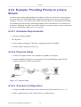
4.3.8. Example: Providing Priority to a Voice Stream .................................... 76
4.3.9. Example: Providing Priority to an IPTV Stream ................................... 85
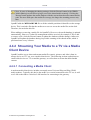
4.4. Sharing Your Media with the Home Network ................................................. 96
4.4.1. Configuring the Media Sharing Service ................................................ 96
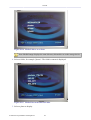
4.4.2. Streaming Your Media to a TV via a Media Client Device ................... 98
4.4.3. Accessing the Shared Media from a LAN Computer .......................... 102
4.5. Utilizing Telephony on Your Gateway ........................................................... 107
© 1998-2010 Jungo Software Technologies Ltd.
iii
4.5.1. Configuring Your Telephone Line Services ........................................ 107
4.5.2. Operating Your Telephone .................................................................. 109
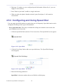
4.5.3. Configuring and Using Speed Dial ...................................................... 110
4.5.4. Sending a Fax ...................................................................................... 112
4.5.5. Customizing Your Phone Service with a Numbering Plan .................. 113
4.5.6. Using Distinctive Ring ........................................................................ 115
4.5.7. Ensuring Constant Connectivity with Failover .................................... 115
4.5.8. Advanced Telephony Options .............................................................. 116
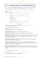
4.6. IP-PBX ............................................................................................................ 126
4.6.1. Configuring Your Analog Extensions .................................................. 127
4.6.2. Operating Your Telephone .................................................................. 128
4.6.3. Connecting VoIP Telephones .............................................................. 130
4.6.4. Opening Telephony Service Accounts ................................................. 134
4.6.5. Defining VoIP Lines ............................................................................ 134
4.6.6. Creating Auto Attendants .................................................................... 139
4.6.7. Handling Incoming Calls ..................................................................... 142
4.6.8. Handling Outgoing Calls ..................................................................... 145
4.6.9. Using the Voice Mail .......................................................................... 148
4.6.10. Adding On-Hold Music Files ............................................................ 150
4.6.11. Automating Call Distribution with Hunt Groups ............................... 151
4.6.12. Advanced Telephony Options ............................................................ 154
4.7. Managing Your Shared Storage ..................................................................... 165
4.7.1. Managing Your File Server ................................................................. 166
4.7.2. Managing Your Disks .......................................................................... 174
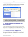
4.8. Accessing Your Network Using a Domain Name .......................................... 186
4.8.1. Opening a Dynamic DNS Account ...................................................... 186
4.9. Configuring Your Gateway's IP Address Distribution .................................... 188
4.9.1. Viewing and Configuring the DHCP Settings ..................................... 189
4.9.2. DHCP Connections .............................................................................. 191
4.10. Parental Control ............................................................................................ 192
4.10.1. Overview ............................................................................................ 193
4.10.2. Filtering Policy .................................................................................. 194
4.10.3. Advanced Options .............................................................................. 196
4.10.4. Statistics ............................................................................................. 197
4.11. Virtual Private Network ................................................................................ 198
4.11.1. Internet Protocol Security .................................................................. 198
4.11.2. Secure Socket Layer VPN ................................................................. 236
4.11.3. Point-to-Point Tunneling Protocol Server .......................................... 253
4.11.4. Layer 2 Tunneling Protocol Server .................................................... 254
4.12. Bluetooth Settings ......................................................................................... 258
5. System ........................................................................................................................ 260
5.1. Viewing the System Information .................................................................... 260
5.2. Setting the Date and Time .............................................................................. 260
5.3. Managing Users .............................................................................................. 263
5.3.1. Adding a User ...................................................................................... 264
5.3.2. Disk Management ................................................................................ 265
5.3.3. E-Mail Notification .............................................................................. 265
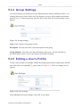
5.3.4. Group Settings ..................................................................................... 266
© 1998-2010 Jungo Software Technologies Ltd.
iv
5.3.5. Editing a User's Profile ........................................................................ 266
5.4. Performing Advanced Management Operations ............................................. 267
5.4.1. Utilizing OpenRG's Universal Plug and Play Capabilities ................... 267
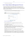
5.4.2. Simple Network Management Protocol ............................................... 271
5.4.3. Enabling Remote Administration ......................................................... 274
5.5. Performing System Maintenance .................................................................... 277
5.5.1. About OpenRG .................................................................................... 277
5.5.2. Rebooting Your Gateway .................................................................... 277
5.5.3. Restoring Factory Settings ................................................................... 278
5.5.4. Upgrading the Gateway's Firmware ..................................................... 278
5.5.5. Replacing OpenRG's MAC Address .................................................... 282
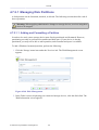
5.6. Creating and Loading Digital Certificates ...................................................... 282
5.6.1. Overview .............................................................................................. 282
5.6.2. OpenRG Certificate Stores .................................................................. 284
II. Appendix ........................................................................................................................... 296
6. Configuring a Computer's Network Interface ............................................................ 298
7. Licensing Acknowledgement and Source Code Offering .......................................... 300
8. Contact Jungo ............................................................................................................ 301
© 1998-2010 Jungo Software Technologies Ltd.
v
Part I Managing Your Gateway
© 1998-2010 Jungo Software Technologies Ltd.
1
Table of Contents
1.
2.
3.
4.
5.
Accessing the Management Console ..................................................................................... 3
Home ...................................................................................................................................... 6
Internet Connection ............................................................................................................. 28
Services ................................................................................................................................ 31
System ................................................................................................................................ 260
© 1998-2010 Jungo Software Technologies Ltd.
2
1
Accessing the Management
Console
This chapter describes how to use OpenRG's management console, referred to as the Webbased Management (WBM), which allows you to configure and control all of OpenRG's
features and system parameters, using a user-friendly graphical interface. This user-friendly
approach is also implemented in the WBM's documentation structure, which is based directly
on the WBM's structure. You will find it easy to correspondingly navigate through both the
WBM and its documentation.
Note: Access to the WBM is restricted to wired clients and Web-authenticated or secured
wireless clients. In addition, some of the documented WBM features may appear slightly
different or may not be available on certain platforms.
To access the Web-based management:
1. Launch a Web browser on a computer in the LAN.
2. In the address bar, type the gateway's name or IP address. The default name is
'http://openrg.home' and the default IP address is 192.168.1.1. The WBM's homepage
appears.
By default, OpenRG's WBM is displayed in read-only basic mode, providing you with the
ability to view your features and system parameters. This mode prevents accessing and
changing the gateway's settings, misconfiguration of which may harm its performance.
© 1998-2010 Jungo Software Technologies Ltd.
3
Accessing the Management Console
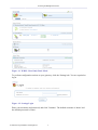
Figure 1.1 WBM – Read Only Basic Mode
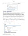
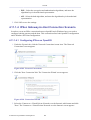
To perform configuration actions on your gateway, click the 'Settings' tab. You are required to
log in.
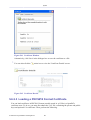
Figure 1.2 Settings Login
Enter your username and password, and click 'Continue'. The default username is 'home' and
the default password is 'home'.
© 1998-2010 Jungo Software Technologies Ltd.
4
Accessing the Management Console
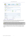
Figure 1.3 WBM – Configuration Mode
By logging in, you have switched from read-only mode to configuration mode. You can now
perform various configurations of your gateway, as described in the following sections. To
return to read-only mode, click the 'Logout' link located on the top bar.
Warning: Misconfiguration of the gateway may harm its performance. Therefore, it is
highly recommended that you refrain from accessing the advanced configuration mode,
unless you have strong technical knowledge of the gateway's advanced features.
A login session will automatically time-out after an extended period of inactivity. If you try
to operate the WBM after the session has expired, the 'Login' screen will appear. This feature
helps to prevent unauthorized users from accessing your session and changing the gateway's
settings.
© 1998-2010 Jungo Software Technologies Ltd.
5
2
Home
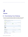
2.1 Overviewing Your Gateway
The 'Overview' screen presents the status of OpenRG's various modules in one convenient
location. You can quickly and efficiently view important system details such as the status of
your Internet connection, wireless and local networks, as well as hardware peripherals.
Figure 2.1 Home – Overview
© 1998-2010 Jungo Software Technologies Ltd.
6
Home
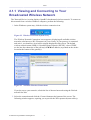
2.1.1 Viewing and Connecting to Your
Broadcasted Wireless Network
The 'Network Devices' section displays OpenRG's broadcasted wireless network. To connect to
this network from a wireless Windows computer, perform the following:
1. In the Windows system tray, click the wireless connection icon.
Figure 2.2 Wireless Icon in the System Tray
The 'Wireless Network Connection' screen appears, displaying all available wireless
networks (also known as Wi-Fi hotspots) in your vicinity. If your gateway is connected
and active, you should see its wireless network displayed in this screen. The default
wireless network name (SSID) is "OpenRG Home Network (XXXX)", where XXXX
are the last four characters of the gateway's CM MAC address (as printed on the sticker
located at the bottom of the gateway).
Figure 2.3 Available Wireless Connections
If you do not see your network, refresh the list of detected networks using the 'Refresh
network list' link.
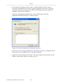
2. Select the connection and click the 'Connect' button at the bottom of the screen. The
following window appears, requiring you to provide the WPA password (network key).
© 1998-2010 Jungo Software Technologies Ltd.
7
Home
Figure 2.4 WPA Network Key Authentication
Enter the WPA password. This case sensitive password can be found on the sticker located
at the bottom of the gateway, and can be changed in the 'Wireless' menu item under the
'Home' tab. After the connection is established, its status changes to 'Connected'.
Figure 2.5 Connected Wireless Network
A balloon appears in the notification area, announcing the successful initiation of the
wireless connection.
Figure 2.6 Wireless Connection Information
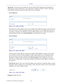
3. If you had selected the default "Medium" security level during the installation wizard,
any attempt to browse the Internet will require Web authentication. The following screen
appears, requiring you to provide your username and password.
Figure 2.7 Web Authentication
© 1998-2010 Jungo Software Technologies Ltd.
8
Home
Enter your username and password. You will be redirected to your requested Internet
address.
In case you have forgotten your wireless password, click 'Forgot your password?'
to display a screen that offers a number of password recovery methods. For more
information, refer to the 'Recovering Your Wireless Network's Password' section of the
OpenRG Administrator Manual.
4. Open an Internet browser and browse to any site.
The 'Home' tab will now display the connected wireless computer.
Figure 2.8 Connected Wireless Computer
2.1.2 Viewing the Local Network
The 'Network Devices' section also displays OpenRG's local network, which includes all
computers that have joined the gateway's network, their IP addresses, and connection speed
(Figure 2.1).
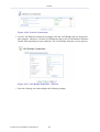
To view more information on a specific computer, click its respective link. The 'Host
Information' screen appears.
© 1998-2010 Jungo Software Technologies Ltd.
9
Home
Figure 2.9 Host Information
This screen presents all of the information relevant to the connected computer, such as
connection information, available services, and traffic statistics.
Services This section lists the services on the computer that are available to other computers
from the LAN. When a service is accessible from the LAN, you can activate it by clicking its
name. When a service is accessible via Web access, you can activate it by clicking the 'Web
Access' link that appears.
Connection Information This section displays various details regarding the computer's
connection settings.
Statistics This section displays the computer's traffic statistics, such as the number and size
of transmitted and received packets.
Connection List This section displays the list of connections opened by the computer on
OpenRG's firewall. The table displays the computer's source LAN IP address and port, the
gateway's IP address and port to which it is translated, and the destination WAN IP address and
port.
2.1.3 Authenticating Wireless Network Devices
When attempting to connect to the gateway's network from a wireless computer, a login session
is used for authentication and connection. However, you may wish connect other wireless
devices to the gateway, such as gaming devices, cameras, etc., in which a login session in is
© 1998-2010 Jungo Software Technologies Ltd.
10
Home
not possible due to the lack of an interface. In such a case, a simple authentication procedure is
required in the 'Home' screen.
A preliminary step is to search for the gateway's wireless network from the device itself. Refer
to the device's documentation to learn how to perform this search. When OpenRG detects a
wireless request, the device is displayed under the relevant wireless connection.
Figure 2.10 Wireless Authentication – Pending
To allow this device to connect to your gateway, click 'Allow'. The screen refreshes, updating
the status of the device.
Figure 2.11 Wireless Authentication – Authenticated
The device is now connected. Similarly, you can use the 'Block' link in order to log the device
out of your network.
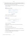
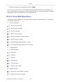
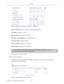
2.1.4 Viewing Attached Devices
The 'Attached Devices' section displays the peripheral devices connected to your gateway.
These may include storage devices and telephones. For example, connect a storage device and
refresh the screen.
Figure 2.12 Connected Storage Device
Note: The 'Phones' section displays the phone extensions even when there are no
connected telephones.
Similarly, this section displays other devices connected to the gateway. For more information
on each device type, refer to its respective section of this manual.
© 1998-2010 Jungo Software Technologies Ltd.
11
Home
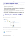
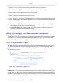
2.1.5 Viewing the System Status
The 'System Status' section of the 'Home' tab (see Figure 2.1 ) displays the following details:
• The Internet connection's type, speed capability, and data transmission mode. Click the
'Internet Connection' link for more details.
• The top five bandwidth consuming applications and computers are displayed in their
respective sections in descending order. The current downstream and upstream volumes are
also displayed for every application and computer.
• Internet connection information, which includes the connection type. Click the 'Internet
Connection' headline for more details.
• System information, which includes the gateway's ID, software version and uptime. Click
the 'System Information' headline for more details.
2.2 Viewing Your Network with Map
View
The 'Map View' screen displays a graphical network map.
Figure 2.13 Home – Map View
The network map depicts the various network elements, such as the Internet connection,
firewall, gateway, and local network computers and peripherals.
Represents the Internet
© 1998-2010 Jungo Software Technologies Ltd.
12
Home
Represents the gateway's Firewall. Click this icon to configure your security
settings. For more information, refer to the 'Firewall' section of the OpenRG
Administrator Manual.
Represents your gateway
The network map dynamically represents the network objects connected to your gateway.
OpenRG recognizes commercial operating systems and game devices, which are represented
by their respective icons.
Represents a wired/wireless computer (host) connected to the gateway. This
host is either a DHCP client that has received an IP lease from OpenRG, or a
host with a static IP address, auto-detected by OpenRG. Note that OpenRG
will recognize a physically connected host and display it in the Network
Map only after network activity from that host has been detected (e.g. trying
to browse to the WBM or to surf the Internet). OpenRG will also display
incoming connections of types PPTP, L2TP, and IPSec. Click this icon to
view network information for the corresponding host.
Represents a host whose DHCP lease has expired and not renewed. The
DHCP lease is renewed automatically, unless the host is no longer physically
connected to OpenRG. The disconnected host's icon will disappear from
the network map during the next scheduled IP lease query, performed by
OpenRG's DHCP server.
Note: This icon also represents a static IP host that has no network
activity.
Represents a Windows™ host connected to your gateway.
Represents a wireless host connected to your gateway.
Represents a printer connected to your gateway.
Represents a telephone connected to your gateway.
© 1998-2010 Jungo Software Technologies Ltd.
13
Home
Represents a USB stick (disk-on-key) connected to your gateway.
Represents a USB hard drive connected to your gateway.
OpenRG's standard network map displays devices that the gateway recognized and granted a
DHCP lease.
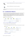
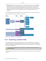
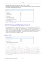
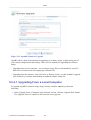
2.3 Installation Wizard
The installation wizard is the first and foremost configuration procedure, which automatically
diagnoses your network environment and configures its components. It is a step-by-step
procedure that guides you through establishing an Internet connection, a wireless network,
and helps you to subscribe for different services by creating a Jungo.net account. The wizard
progress box, located at the right hand side of the screen, provides a monitoring tool for its
steps during the installation progress.
Figure 2.14 Welcome to OpenRG Installation Wizard
To start the installation wizard, perform the following:
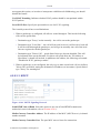
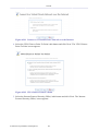
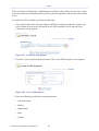
1. Select the desired language and click 'Next' to continue. The 'Login Setup' screen appears.
Figure 2.15 Login Setup
© 1998-2010 Jungo Software Technologies Ltd.
14
Home
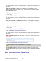
2. Enter a valid email address. It will be used by your service provider for sending you
important service information.
3. The 'User Name' field is auto-completed by the username part of your email address. You
can enter another username, which may only consist of letters and numbers.
4. Enter a password, and retype it in the next field to verify its correctness.
Note: It is recommended to write down your login details on a piece of paper, and
store it in a safe place.
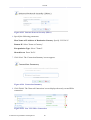
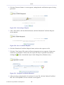
5. Click 'Next'. The wizard is now ready to begin your gateway's configuration.
Figure 2.16 Installation Wizard
6. Click 'Next'. The wizard procedure will commence, performing the steps listed in the
progress box consecutively, stopping only if a step fails or if input is required. The
following sections describe the wizard steps along with their success/failure scenarios. If a
step fails, use the 'Retry' or 'Skip' buttons to continue.
Warning: The installation wizard overrides all Internet connection settings, which you
may have previously defined.
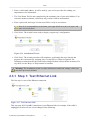
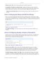
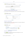
2.3.1 Step 1: Test Ethernet Link
The first step is a test of the Ethernet connection.
Figure 2.17 Test Ethernet Link
This step may fail if OpenRG cannot detect your Ethernet link (for example, if the cable is
unplugged). In this case, the screen changes to the following.
© 1998-2010 Jungo Software Technologies Ltd.
15
Home
Figure 2.18 Test Ethernet Link – Failure
Verify that your Ethernet/DSL cable is connected properly, and click 'Retry'.
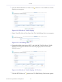
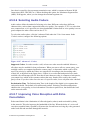
2.3.2 Step 2: Analyze Internet Connection Type
The next step is an analysis of your Internet connection.
Figure 2.19 Analyze Internet Connection Type
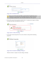
This step may fail if OpenRG is unable to detect your Internet connection type.
Figure 2.20 Analyze Internet Connection Type – Failure
In this case, you can manually set the Internet connection type, by clicking the corresponding
button. The following screen appears.
© 1998-2010 Jungo Software Technologies Ltd.
16
Home
Figure 2.21 Manual Internet Connection Type Setup
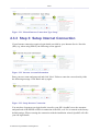
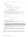
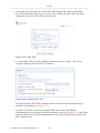
2.3.3 Step 3: Setup Internet Connection
If your Internet connection requires login details provided by your Internet Service Provider
(ISP) (e.g. when using PPPoE), the following screen appears.
Figure 2.22 Internet Account Information
Enter your user name and password and click 'Next'. Failure to enter the correct details yields
the following message. Click 'Back' and try again.
Figure 2.23 Setup Internet Connection
You may have forgotten your login details, issued by your ISP. OpenRG saves the username
and password of the PPPoE or PPPoA connection to the ISP, even if it is restored to the factory
default settings. When restoring the connection with the installation wizard, OpenRG will offer
your old login details.
© 1998-2010 Jungo Software Technologies Ltd.
17
Home
Figure 2.24 Internet Account Information
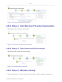
2.3.4 Step 4: Test Service Provider Connection
This step tests the connectivity to your ISP.
Figure 2.25 Test Service Provider Connection
2.3.5 Step 5: Test Internet Connection
This step tests the connectivity to the Internet.
Figure 2.26 Test Internet Connection
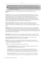
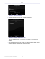
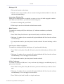
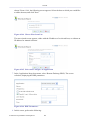
2.3.6 Step 6: Wireless Setup
This step enables you to rename your wireless network, as well as change its security level.
© 1998-2010 Jungo Software Technologies Ltd.
18
Home
Figure 2.27 Wireless Setup
OpenRG assigns a default name for its wireless network, which you may later change. Select
the wireless security level. The default "Medium" level secures your network by requiring
users to provide a password in order to connect. "High" level utilizes the Wi-Fi Protected
Access (WPA) protocol, requiring a password (network key) as well, but also encrypts the
wireless traffic. When selecting this option, enter an eight-character password in the provided
field. Click 'Next' to continue.
2.3.6.1 Setup via Wireless Connection
If you are running the installation wizard while being connected to OpenRG via a wireless
connection, the wizard does not change the default SSID (to prevent you from disconnecting).
If you choose to change it manually, the following screen appears, requesting that you reestablish your wireless connection (from your computer) before proceeding with the wizard.
Figure 2.28 Wireless Setup
This screen also appears after selecting the High wireless security level, or after changing the
previously entered WPA password (see Figure 2.27).
© 1998-2010 Jungo Software Technologies Ltd.
19
Home
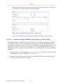
2.3.6.2 Additional SSIDs with Virtual Access Points
If your gateway supports multiple virtual access points, an additional pre-configured WPAsecured wireless network is displayed in 'Wireless Setup' screen.
Figure 2.29 Wireless Setup
You can change the default name and network key (password) of this encrypted wireless
network in their respective text fields (clicking 'Next' will save the new details). This wireless
network will also appear in the 'Network Connections' screen under the 'System' tab, where it
can be edited or deleted such as any other network connection.
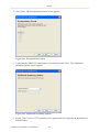
Figure 2.30 Network Connections
Note: In order to delete this connection, you must first remove it from under the LAN
bridge.
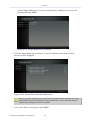
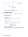
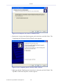
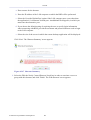
2.3.7 Step 10: Installation Completed
This screen provides a summary of all the above Internet connection configuration steps and
their results. Click 'Finish' to complete the wizard procedure.
© 1998-2010 Jungo Software Technologies Ltd.
20
Home
Figure 2.31 Installation Completed
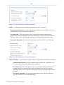
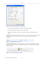
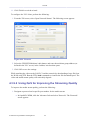
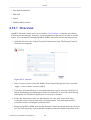
2.4 Configuring Your Wireless
Connection
The 'Wireless' menu item concentrates the wireless LAN settings of your gateway. This screen
presents OpenRG's wireless connection settings, and enables you to change them according to
your needs.
Figure 2.32 Wireless Overview
© 1998-2010 Jungo Software Technologies Ltd.
21
Home
Warning: Misconfiguration of this interface may harm its performance and result
in an inoperable gateway. Therefore, it is highly recommended that you refrain from
changing the default settings, unless you have a strong knowledge and understanding
of the interface's parameters.
Enable Wireless Select or deselect this check box to enable or disable the wireless
interface.
Channel All devices in your wireless network broadcast on different channels. Leaving
this parameter on Automatic ensures that OpenRG continuously scans for the most available
wireless channel in your area. It is possible to select a channel manually if you have
information regarding the wireless channels used in your vicinity. The channels available
depend on the regulatory authority (stated in brackets) to which your gateway conforms. For
example, the European regulatory authority (ETSI) has allocated 13 available channels, while
the US regulatory authority (FCC) has allocated 11 available channels.
Network Name (SSID) The SSID is the network name shared among all points in a
wireless network. It is case-sensitive and must not exceed 32 characters (use any of the
characters on the keyboard). For added security, you may change the default SSID to a unique
name.
SSID Broadcast By default, OpenRG broadcasts the name of its wireless network (SSID).
For security reasons, you may choose to hide your wireless network by deselecting this check
box. Wireless clients will only be able to connect by manually typing the SSID in their wireless
client applications (whether Windows or a third party application), rather than choosing it from
the list of available wireless networks.
802.11 Mode Select the desired wireless connection type. By default, it is set to 802.11g/n.
Note that 802.11b legacy devices are not compatible with modes 802.11g/n and 802.11g Only.
Allow management from wireless clients Select this check box if you wish to allow
authenticated wireless clients to access your gateway's WBM.
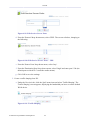
Security Use this section to configure your wireless security settings. Select the type of
security protocol from the corresponding drop-down menu. The screen refreshes, presenting
each protocol's configuration respectively.
• WPA – a data encryption method for 802.11 wireless LANs.
Authentication Method Select the authentication method you would like to use. You
can choose between Pre-Shared Key and 802.1x.
Pre-Shared Key This entry appears only if you had selected this authentication
method. Enter your encryption key in the 'Pre-Shared Key' field. You can use either an
ASCII or a Hex value by selecting the value type in the drop-down menu provided.
Encryption Algorithm Select between Temporal Key Integrity Protocol (TKIP) and
Advanced Encryption Standard (AES) for the encryption algorithm, or both of them.
© 1998-2010 Jungo Software Technologies Ltd.
22
Home
Figure 2.33 WPA Wireless Security Parameters
• WPA2 – an enhanced version of WPA, and defines the 802.11i protocol.
Authentication Method Select the authentication method you would like to use. You
can choose between Pre-Shared Key and 802.1x.
Pre-Shared Key This entry appears only if you had selected this authentication
method. Enter your encryption key in the 'Pre-Shared Key' field. You can use either an
ASCII or a Hex value by selecting the value type in the drop-down menu provided.
Encryption Algorithm The encryption algorithm used with WPA2 is the AES only.
Figure 2.34 WPA2 Wireless Security Parameters
• WPA and WPA2 – a mixed data encryption method, which utilizes both WPA and WPA2.
Authentication Method Select the authentication method you would like to use.
You can choose between Pre-Shared Key and 802.1x.
Pre-Shared Key This entry appears only if you had selected this authentication
method. Enter your encryption key in the 'Pre-Shared Key' field. You can use
either an ASCII or a Hex value by selecting the value type in the drop-down menu
provided.
Encryption Algorithm The encryption algorithm used for WPA and WPA2 is
either the AES only, or both AES and TKIP.
© 1998-2010 Jungo Software Technologies Ltd.
23
Home
Wireless Password The wireless password required to connect to the gateway's
wireless network. You may change the default password by either clicking 'Generate' or
entering an 8 character long password, and clicking 'Apply'. Note that clicking 'Reset' will
return the gateway's default password.
Figure 2.35 WPA and WPA2
• WEP – a data encryption method utilizing a statically defined key as the wireless password.
Note that the static key must be defined in the wireless Windows client as well, as described
below.
Active Select the encryption key to be activated.
Key Length Select the key length in bits: 40 or 104 bits.
Encryption Key Type Select the character type for the key: ASCII or HEX.
Wireless Password Enter the wireless password required to connect to the gateway's
wireless network.
Figure 2.36 WEP
The encryption key (wireless password) must be defined in the wireless Windows computer
as well. This is done in the 'Connection Properties Configuration' window:
© 1998-2010 Jungo Software Technologies Ltd.
24
Home
Figure 2.37 Connection Properties Configuration
1. In the 'Network Authentication' drop-down menu, select "Shared".
2. In the 'Data Encryption' drop-down menu, select "WEP".
3. Enter your encryption key in both the 'Network key' and the 'Confirm network key'
fields.
• Unsecured Selecting this option disables security on your wireless connection. Any wireless
computer in your area will be able to connect to the Internet using your connection's
bandwidth.
Figure 2.38 Disabled Wireless Security
• Authentication Only When selecting this option, wireless clients attempting to connect to
the wireless connection will receive OpenRG's main login screen, along with the following
attention message:
Figure 2.39 Web Authentication Needed
© 1998-2010 Jungo Software Technologies Ltd.
25
Home
By logging into the WBM, clients authenticate themselves and are then able to use the
connection. OpenRG keeps record of authenticated clients. To clear this list, click the 'Clean
Mac List' button. Clients will have to re-authenticate themselves in order to use the wireless
connection.
Figure 2.40 Authentication Only Wireless Security Parameters
Wi-Fi Protected Setup (WPS) WPS is a method for simplifying the security setup and
management of wireless networks.
Status Indicates the WPS status. "Ready" means that the system is ready to negotiate with
incoming wireless clients, or "enrollees".
Protected Setup Method OpenRG supports two setup methods, "Push Button" (the
default) and "Client Pin Code". These are the methods used by wireless clients when seeking
an access point.
• Push Button – The enrollment is initiated by either pressing a physical button on the
wireless client or through its software. After initiating the enrollment, click 'Go' or press
the WPS button on the top of the gateway for the devices to establish a connection.
• Client Pin Code – The enrollment is initiated by the wireless client's software, which also
provides a pin code. To comply with this method, select this option from the drop-down
menu. The screen refreshes to provide a field for entering the pin code:
Figure 2.41 Protected Setup Method – Pin Code
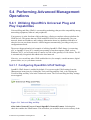
In this field, enter the eight digit pin code provided by the wireless client's software. Click
'Go' for the devices to establish a connection.
When attempting to connect a wireless client to OpenRG, you must be aware of its setup
method. A connection attempt will time out after two minutes if no connection is established.
If a connection is established, the 'Status' field will change to reflect that.
© 1998-2010 Jungo Software Technologies Ltd.
26
Home
Figure 2.42 Successful Enrollee Registration
Note that WPS is only supported with WPA security. Therefore, when 'WEP' or 'Unsecured'
are selected in the 'Security' drop-down menu, the following message appears in the WPS
section.
Figure 2.43 WPS Not Supported
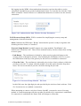
MAC Filtering You can filter wireless clients according to their MAC addresses, either
allowing or denying them access to your wireless network. To add a MAC filtering rule,
choose the action to be performed (allow or deny) in the drop-down menu. Then, click 'New
MAC Address'. The 'MAC Filtering Settings' screen appears.
Figure 2.44 MAC Filtering Settings
Enter the MAC address (in hexadecimal values) to be filtered and click 'OK'. The MAC
address entry appears.
Figure 2.45 MAC Filtering Entry
Note that when 'Allow' is selected, only wireless clients listed in this table will be able to
connect. When 'Deny' is selected, all but wireless clients listed will be able to connect.
© 1998-2010 Jungo Software Technologies Ltd.
27
3
Internet Connection
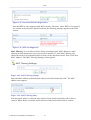
3.1 Viewing Your Internet Connection
Properties
The 'Overview' screen provides general information regarding your Internet connection,
such as the connection's status, protocol, speed, duration, as well as the gateway's external
IP address and networking parameters. You can use this screen to quickly view your Internet
connection status.
Figure 3.1 Internet Connection – Overview
© 1998-2010 Jungo Software Technologies Ltd.
28
Internet Connection
The following links are available:
• Have Internet Connection problems? Click here This link routes you to the 'Troubleshoot'
screen, where you can run tests in order to diagnose and resolve Internet connectivity
problems.
• Click Here For Internet Connection Utilization Click this link to analyze the traffic usage
of your WAN connection (for more information, refer to Section 4.3).
In addition, this screen displays OpenRG's top bandwidth consuming applications and
computers, described in Section 4.3.2.
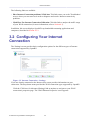
3.2 Configuring Your Internet
Connection
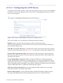
The 'Settings' screen provides basic configuration options for the different types of Internet
connections supported by OpenRG.
Figure 3.2 Internet Connection – Settings
If you are already connected to the Internet, this screen provides information on your
connection. The drop-down menu provides the WAN connection types supported by OpenRG.
Click the 'Click here for Advanced Settings' link at anytime to navigate to your WAN
connection's properties page. The 'WAN Ethernet Properties' screen appears.
© 1998-2010 Jungo Software Technologies Ltd.
29
Internet Connection
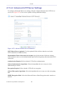
Figure 3.3 WAN Ethernet Properties
This screen provides all the configuration options for your WAN connection. For more
information, refer to the 'WAN Ethernet' network connection in the 'System' chapter of the
Administrator Manual.
© 1998-2010 Jungo Software Technologies Ltd.
30
4
Services
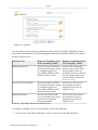
4.1 Overviewing Your Services
The 'Overview' screen presents a summary of OpenRG's services and their current status
(enabled/disabled). These services are configurable via their respective menu items under the
'Services' tab.
Figure 4.1 Services Overview
© 1998-2010 Jungo Software Technologies Ltd.
31
Services
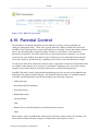
4.2 Securing Your Network with the
Firewall
OpenRG's gateway security suite includes comprehensive and robust security services:
Stateful Packet Inspection Firewall, user authentication protocols and password protection
mechanisms. These features together allow users to connect their computers to the Internet
and simultaneously be protected from the security threats of the Internet. The firewall, RGFW OpenRG™, the cornerstone of your gateway's security suite, has been exclusively tailored
to the needs of the residential/office user and has been pre-configured to provide optimum
security (see Figure 4.2).
Figure 4.2 OpenRG's Firewall in Action
OpenRG's firewall provides both the security and flexibility that home and office users seek.
It provides a managed, professional level of network security while enabling the safe use of
interactive applications, such as Internet gaming and video-conferencing.
Additional features, including browsing restrictions and access control, can also be easily
configured locally by the user through a user-friendly Web-based interface, or remotely by
a service provider. The OpenRG firewall supports advanced filtering, designed to allow
comprehensive control over the firewall's behavior. You can define specific input and output
rules, control the order of logically similar sets of rules and make a distinction between rules
that apply to WAN and LAN network devices.
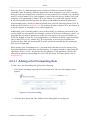
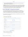
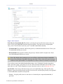
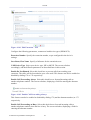
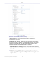
4.2.1 Configuring Basic Security Settings
The 'General' screen enables you to configure the gateway's basic security settings.
© 1998-2010 Jungo Software Technologies Ltd.
32
Services
Figure 4.3 General
You may choose between three pre-defined security levels for OpenRG: Minimum, Typical
(the default), and Maximum. The following table summarizes OpenRG's behavior for each of
the three security levels.
Security Level
Requests Originating in the
WAN (Incoming Traffic)
Requests Originating in the
LAN (Outgoing Traffic)
Maximum Security
Blocked: No access to home
network from Internet, except
as configured in the Port
Forwarding, DMZ host and
Remote Access screens
Limited: Only commonlyused services, such as Webbrowsing and e-mail, are
permitted. The list of allowed
services can be edited in the
Access Control screen (refer
to Section 4.2.2)
Typical Security (Default)
Blocked: No access to home
network from Internet, except
as configured in the Port
Forwarding, DMZ host and
Remote Access screens
Unrestricted: All services
are permitted, except as
configured in the Access
Control screen
Minimum Security
Unrestricted: Permits full
access from Internet to home
network; all connection
attempts permitted
Unrestricted: All services
are permitted, except as
configured in the Access
Control screen
Table 4.1 OpenRG's Firewall Security Levels
To configure OpenRG's basic security settings, perform the following:
1. Choose between the three predefined security levels described in the table above.
© 1998-2010 Jungo Software Technologies Ltd.
33
Services
Note: Using the Minimum Security setting may expose the home network to
significant security risks, and thus should only be used, when necessary, for short
periods of time.
2. Check the 'Block IP Fragments' box in order to protect your home network from a
common type of hacker attack that could make use of fragmented data packets to sabotage
your home network. Note that VPN over IPSec and some UDP-based services make
legitimate use of IP fragments. In case of enabling these services, you will need to allow IP
fragments to pass into the home network.
3. Click 'OK' to save the settings.
By default, the selected security level is applied on such services as Telnet, FTP, HTTP,
HTTPS, DNS, IMAP, POP3 and SNTP. Note that some applications (such as some Internet
messengers and Peer-To-Peer client applications) tend to use ports of the above-mentioned
services, if these applications cannot connect using their own default ports. When allowing
this behavior, the applications' outbound connection requests will not be blocked, even at the
Maximum Security level.
After the security level is set, the firewall regulates the flow of data between the home network
and the Internet. Both incoming and outgoing data are inspected and then either accepted
(allowed to pass through OpenRG) or rejected (barred from passing through OpenRG),
according to a flexible and configurable set of rules. These rules are designed to prevent
unwanted intrusions from the outside, while allowing home users access to the Internet services
that they require.
The firewall rules specify what types of services available on the Internet may be accessed
from the home network and what types of services available in the home network may be
accessed from the Internet. Each request for a service that the firewall receives, whether
originating from the Internet or from a computer in the home network, is checked against the
set of firewall rules to determine whether the request should be allowed to pass through the
firewall. If the request is permitted to pass, then all subsequent data associated with this request
(a "session") will also be allowed to pass, regardless of its direction.
For example, when you point your browser to a Web page, a request is sent out to the Internet
for retrieving and loading this page. When the request reaches OpenRG, the firewall identifies
the request's type and origin—HTTP and a specific PC in your home network, in this case.
Unless you have configured access control to block requests of this type from this computer,
the firewall will allow this request to pass out onto the Internet (refer to Section 4.2.2 for more
on setting OpenRG's access control).
When the Web page is returned from the Web server, the firewall associates it with this session
and allows it to pass, regardless of whether HTTP access from the Internet to the home network
is blocked or permitted. It is the origin of the request, not the subsequent responses to this
request, that determines whether a session can be established or not.
© 1998-2010 Jungo Software Technologies Ltd.
34
Services
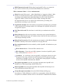
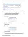
4.2.2 Controlling Access to Internet Services
You may want to block specific computers within the home network (or even the whole
network) from accessing certain services on the Internet. For example, you may want to
prohibit one computer from browsing the Web, another computer from transferring files using
FTP, and the whole network from receiving e-mail (by blocking the outgoing requests to POP3
servers on the Internet). The 'Access Control' screen enables you to define restrictions on
the types of requests that may pass from the home network out to the Internet, and thus may
block traffic flowing in both directions. It can also be used for allowing specific services when
maximum security is configured.
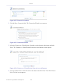
• To allow or restrict services:
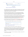
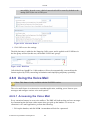
1. Click 'Access Control' under the 'Firewall' menu item. The 'Access Control' screen
appears.
Figure 4.4 Access Control
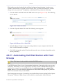
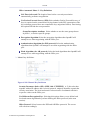
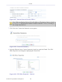
2. Click the 'New Entry' link. The 'Add Access Control Rule' screen appears.
Figure 4.5 Add Access Control Rule
3. The 'Address' drop-down menu enables you to specify the computer or group of
computers on which you would like to apply the access control rule. Select an address
or a name from the list to apply the rule on the corresponding host, or 'Any' to apply
the rule on all OpenRG's LAN hosts. If you would like to add a new address, select the
'User Defined' option in the drop-down menu. This will commence a sequence that will
add a new Network Object, representing the new host.
© 1998-2010 Jungo Software Technologies Ltd.
35
Services
4. The 'Protocol' drop-down menu enables you to select or specify the type of protocol
that will be used. Selecting the 'Show All Services' option expands the list of available
protocols. Select a protocol or add a new one using the 'User Defined' option. This will
commence a sequence that will add a new Service, representing the protocol.
5. Select the 'Reply an HTML page to the blocked client' check box to display the
following message to the client: "Access Denied – this computer is not allowed to surf
the WAN. Please contact your admin.". When this check box is deselected, the client's
packets are simply ignored and no notification is issued.
6. By default, the rule will always be active. However, you can define time segments
during which the rule may be active, by selecting 'User Defined' from the 'Schedule'
drop-down menu. If more than one scheduler rule is defined, the 'Schedule' dropdown menu will allow you to choose between the available rules. To learn how to
configure scheduler rules, refer to the 'Defining Scheduler Rules' section of the
OpenRG Administrator Manual.
7. Click 'OK' to save your changes. The 'Access Control' screen displays a summary of the
rule that you have just added.
Figure 4.6 Access Control Rule
You may edit the access control rule by modifying its entry displayed under the 'Local Host'
column.
• To modify a rule's entry:
1.
Click the rule's
action icon . The 'Edit Access Control Rule' screen appears. This
screen allows you to edit all the parameters that you configured when creating the
access control rule.
© 1998-2010 Jungo Software Technologies Ltd.
36
Services
Figure 4.7 Edit Access Control Rule
2. Click 'OK' to save your changes and return to the 'Access Control' screen.
You can disable an access control rule in order to make a service available without having
to remove the rule from the 'Access Control' screen. This may be useful if you wish to make
the service available only temporarily, intending to reinstate the restriction in the future.
• To temporarily disable a rule, clear the check box next to the service name.
• To reinstate it at a later time, simply reselect the check box.
• To remove a rule, click the service's
removed.
action icon . The service will be permanently
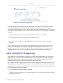
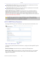
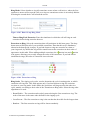
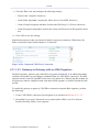
When the 'Maximum' security level is applied, the 'Access Control' screen also displays a list
of automatically generated firewall rules that allow access to specific Internet services from the
LAN computers, over pre-defined ports.
© 1998-2010 Jungo Software Technologies Ltd.
37
Services
Figure 4.8 Access Control – Allowed Services in Maximum Security Mode
You can manage these access control rules as well as create new ones (allowing access to
other services), as described earlier in this section.
Note: When the Parental Control service is enabled (refer to Section 4.10), HTTP
services cannot be blocked by Access Control.
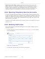
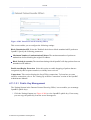
4.2.3 Using Port Forwarding
In its default state, OpenRG blocks all external users from connecting to or communicating
with your network. Therefore, the system is safe from hackers who may try to intrude into
the network and damage it. However, you may wish to expose your network to the Internet in
certain limited and controlled ways. The Port Forwarding feature enables you to do so. If you
are familiar with networking terminology and concepts, you may have encountered the port
forwarding capability referred to as "Local Servers".
The 'Port Forwarding' screen enables you to define applications (such as Peer-to-Peer, game,
voice, chat programs, etc.) that will be allowed a controlled Internet activity. For example,
if you wish to use a File Transfer Protocol (FTP) application on one of your PCs, you would
simply create a port forwarding rule, which specifies that all FTP-related data arriving at
OpenRG from the Internet will henceforth be forwarded to the specified computer.
Similarly, you can grant Internet users access to servers inside your home network, by
identifying each service and the PC that will provide it. This is useful, for example, if you
would like to host a Web server inside your home network. When an Internet user points
a browser to OpenRG's external IP address, the gateway will forward the incoming HTTP
request to your Web server, if the corresponding port forwarding rule had been set.
© 1998-2010 Jungo Software Technologies Ltd.
38
Services
However, there is a limitation that must be considered. With one external IP address
(OpenRG's main IP address), different applications can be assigned to your LAN computers,
however each type of application is limited to use one computer. For example, you can define
that FTP will use address X to reach computer A and Telnet will also use address X to reach
computer A, but attempting to define FTP to use address X to reach both computer A and
B will fail. OpenRG therefore provides the ability to add additional public IP addresses to
port forwarding rules, which you must first obtain from your ISP, and enter into the 'NAT IP
Addresses Pool' (refer to Section 4.2.6). You will then be able to define FTP to use address X
to reach computer A, and address Y to reach computer B.
Additionally, port forwarding enables you to redirect traffic to a different port instead of the
one for which it was designated. For example, you have a Web server running on your PC on
port 8080 and you want to grant access to this server to anyone who accesses OpenRG via
HTTP (by default, on port 80). To accomplish this, you will have to define a port forwarding
rule for the HTTP service, with the PC's IP or host name, as well as specify 8080 in the
'Forward to Port' field. All incoming HTTP traffic will be forwarded to the PC running the
Web server on port 8080.
When setting a port forwarding service, you must ensure that the port is not already in use
by another application, which may stop functioning. A common example is when using SIP
signaling in Voice over IP—the port used by the gateway's VoIP application (5060) is the
same port on which port forwarding is set for LAN SIP agents. For more details, refer to
Section 4.5.8.3.
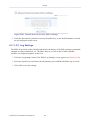
4.2.3.1 Adding a Port Forwarding Rule
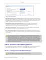
To add a new port forwarding rule, perform the following:
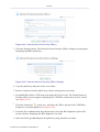
1. Click 'Port Forwarding' under the 'Firewall' menu item. The 'Port Forwarding' screen
appears.
Figure 4.9 Port Forwarding
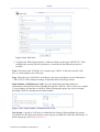
2. Click the 'New Entry' link. The 'Add Port Forwarding Rule' screen appears.
© 1998-2010 Jungo Software Technologies Ltd.
39
Services
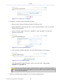
Figure 4.10 Add Port Forwarding Rule
3. The 'Local Host' drop-down menu lists your available LAN computers. Select a computer
that provides the service, to which you wish to grant access over the Internet. Note that
unless an additional external IP address has been added, only one LAN computer can be
assigned to provide a specific service or application.
4. The 'Protocol' drop-down menu enables you to select or specify the type of protocol
that will be used. Selecting the 'Show All Services' option expands the list of available
protocols. Select a protocol or add a new one using the 'User Defined' option. This will
commence a sequence that will add a new Service, representing the protocol.
5. When creating a port forwarding rule, you must ensure that the port used by the selected
protocol is not already in use by any other of your local services, which, in this case, may
stop functioning. A common example is when using SIP signaling in Voice over IP—
the port used by the gateway's VoIP application (5060) is the same port on which port
forwarding is set for LAN SIP agents. For more details, refer to Section 4.5.8.3.
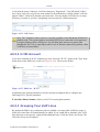
6. If you would like to apply this rule on OpenRG's non-default IP address (which you can
define in the 'NAT' screen, as described in Section 4.2.6), perform the following:
a. Select the 'Specify Public IP Address' check box. The screen refreshes.
Figure 4.11 Specify Public IP Address
b. Enter the additional external IP address in the 'Public IP Address' field.
7. By default, the rule will always be active. However, you can define time segments during
which the rule may be active, by selecting 'User Defined' from the 'Schedule' drop-down
menu. If more than one scheduler rule is defined, the 'Schedule' drop-down menu will
allow you to choose between the available rules. To learn how to configure scheduler
rules, refer to the 'Defining Scheduler Rules' section of the OpenRG Administrator
Manual.
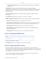
8. Click 'OK' to save your changes. The 'Port Forwarding' screen displays a summary of the
rule that you have just added.
© 1998-2010 Jungo Software Technologies Ltd.
40
Services
Figure 4.12 Port Forwarding Rule
You may edit the port forwarding rule by clicking its entry under the 'Local Host' column
in the 'Port Forwarding' screen. You can also disable the rule in order to make a service
unavailable without having to remove the rule from the 'Port Forwarding' screen. This may be
useful if you wish to make the service unavailable only temporarily, intending to reinstate it in
the future.
• To temporarily disable a rule, clear the check box next to the service name.
• To reinstate it at a later time, simply reselect the check box.
• To remove a rule, click the service's
removed.
action icon . The service will be permanently
All the computers in the local network can simultaneously use a specific service as clients.
Being a client means that the computer within the network initiates the connection—for
example, opens an FTP connection with an FTP server on the Internet. However, only one
computer can serve as a server, responding to requests from computers on the Internet.
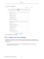
4.2.4 Using Port Triggering
Port triggering is used for setting a dynamic port forwarding configuration. By setting port
triggering rules, you can allow inbound traffic to arrive at a specific LAN host, using ports
different than those used for the outbound traffic. This is called port triggering since the
outbound traffic triggers to which ports inbound traffic is directed.
For example, consider a gaming server that is accessed using the UDP protocol on port 2222.
The gaming server responds by connecting the user using UDP on port 3333, when starting
gaming sessions. In such a case you must use port triggering, since this scenario conflicts with
the following default firewall settings:
• The firewall blocks inbound traffic by default.
• The server replies to OpenRG's IP, and the connection is not sent back to your host, since it
is not part of a session.
© 1998-2010 Jungo Software Technologies Ltd.
41
Services
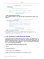
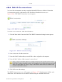
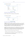
In order to solve this, you need to define a Port Triggering entry, which allows inbound
traffic on UDP port 3333 only after a LAN host generated traffic to UDP port 2222. To do so,
perform the following:
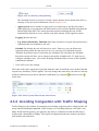
1. Click the 'Port Triggering' link under the 'Firewall' menu item. The 'Port Triggering' screen
appears. This screen will list all of the port triggering entries.
Figure 4.13 Port Triggering
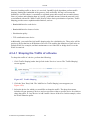
2. Select the 'User Defined' option to add an entry. The 'Edit Port Triggering Rule' screen
appears.
Figure 4.14 Edit Port Triggering Rule
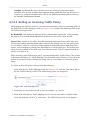
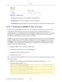
3. Enter a name for the service (e.g. "game_server"), and click the 'New Trigger Ports' link.
The 'Edit Service Server Ports' screen appears.
© 1998-2010 Jungo Software Technologies Ltd.
42
Services
Figure 4.15 Edit Service Server Ports
4. From the 'Protocol' drop-down menu, select 'UDP'. The screen will refresh, providing
source and destination port options (see Figure 4.16).
5. Leave the 'Source Ports' drop-down menu at its default "Any". From the 'Destination Ports'
drop-down menu, select "Single". The screen will refresh again, providing an additional
field in which you should enter "2222" as the destination port.
Figure 4.16 Edit Service Server Ports
6. Click 'OK' to save the settings.
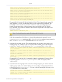
7. Back in the 'Edit Port Triggering Rule' screen (see Figure 4.14), click the 'New Opened
Ports' link. The 'Edit Service Opened Ports' screen appears.
Figure 4.17 Edit Service Opened Ports
© 1998-2010 Jungo Software Technologies Ltd.
43
Services
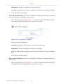
8. Select UDP as the protocol, leave the source port at "Any", and enter a 3333 as the single
destination port.
Figure 4.18 Edit Service Opened Ports
9. Click 'OK' to save the settings. The 'Edit Service' screen will present your entered
information. Click 'OK' again to save the port triggering rule. The 'Port Triggering' screen
will now include the new port triggering entry.
Figure 4.19 New Port Triggering Rule
This will result in accepting the inbound traffic from the gaming server, and sending it back to
the LAN Host which originated the outgoing traffic to UDP port 2222.
• To temporarily disable a rule, clear the check box next to the service name.
• To reinstate it at a later time, simply reselect the check box.
• To remove a rule, click the service's
removed.
action icon . The service will be permanently
Note: There may be a few default port triggering rules listed when you first access
the port triggering screen. Disabling these rules may result in impaired gateway
functionality.
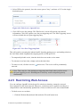
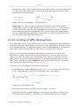
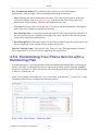
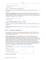
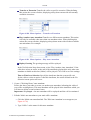
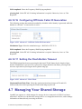
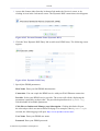
4.2.5 Restricting Web Access
You can configure OpenRG to block specific websites so that they cannot be accessed
from computers in the home network. Moreover, restrictions can be applied according to a
comprehensive and automatically updated list of sites to which access is not recommended.
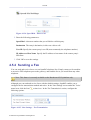
• To block access to a website:
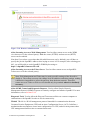
1. Click the 'Website Restrictions' link under the 'Firewall' menu item.
© 1998-2010 Jungo Software Technologies Ltd.
44
Services
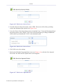
Figure 4.20 Website Restrictions
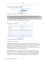
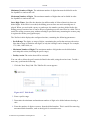
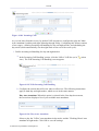
2. Click the 'New Entry' link. The 'Restricted Website' screen appears.
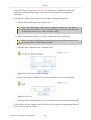
Figure 4.21 Restricted Website
3. Enter the URL (or part of the URL) that you would like to make inaccessible from your
home network (all web pages within this URL will also be blocked). If the URL has
multiple IP addresses, OpenRG will resolve all additional addresses and automatically
add them to the restrictions table.
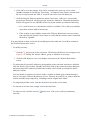
4. The 'Local Host' drop-down menu provides you with the ability to specify the computer
or group of computers on which you would like to apply the website restriction. Select
an address or a name from the list to apply the rule on the corresponding host, or 'Any'
to apply the rule on all OpenRG's LAN hosts. If you would like to add a new address,
select the 'User Defined' option in the drop-down menu. This will commence a sequence
that will add a new Network Object, representing the new host.
5. By default, the rule will always be active. However, you can define time segments
during which the rule may be active, by selecting 'User Defined' from the 'Schedule'
drop-down menu. If more than one scheduler rule is defined, the 'Schedule' dropdown menu will allow you to choose between the available rules. To learn how to
configure scheduler rules, refer to the 'Defining Scheduler Rules' section of the
OpenRG Administrator Manual.
© 1998-2010 Jungo Software Technologies Ltd.
45
Services
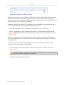
6. Click 'OK' to save the settings. You will be returned to the previous screen, while
OpenRG attempts to find the site. 'Resolving...' will appear in the 'Status' column while
the site is being located (the URL is 'resolved' into one or more IP addresses).
7. Click the 'Refresh' button to update the status if necessary. If the site is successfully
located, then 'Resolved' will appear in the status bar. Otherwise, 'Hostname Resolution
Failed' will appear. In case OpenRG fails to locate the website, perform the following:
a. Use a web browser to verify that the website is available. If it is, then you probably
entered the website address incorrectly.
b. If the website is not available, return to the 'Website Restrictions' screen at a later
time and click the 'Resolve Now' button to verify that the website can be found and
blocked by OpenRG.
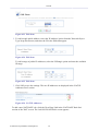
You may edit the website restriction by modifying its entry under the 'Local Host' column in
the 'Website Restrictions' screen.
• To modify an entry:
1.
Click the
action icon for the restriction. The 'Restricted Website' screen appears (see
Figure 4.21). Modify the website address, group or schedule as necessary.
2. Click the 'OK' button to save your changes and return to the 'Website Restrictions'
screen.
• To ensure that all current IP addresses corresponding to the restricted websites are blocked,
click the 'Resolve Now' button. OpenRG will check each of the restricted website addresses
and ensure that all IP addresses at which this website can be found are included in the IP
addresses column.
You can disable a restriction in order to make a website available again without having to
remove it from the 'Website Restrictions' screen. This may be useful if you wish to make the
website available only temporarily, intending to block it again in the future.
• To temporarily disable a rule, clear the check box next to the service name.
• To reinstate it at a later time, simply reselect the check box.
• To remove a rule, click the service's
removed.
© 1998-2010 Jungo Software Technologies Ltd.
action icon . The service will be permanently
46
Services
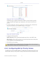
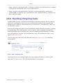
4.2.6 Using OpenRG's Network Address and
Port Translation
OpenRG features a configurable Network Address Translation (NAT) and Network Address
Port Translation (NAPT) mechanism, allowing you to control the network addresses and
ports set in packets routed through your gateway. When enabling multiple computers on your
network to access the Internet using a fixed number of public IP addresses, you can statically
define which LAN IP address will be translated to which NAT IP address and/or ports.
By default, OpenRG operates in NAPT routing mode. However, you can control your network
translation by defining static NAT/NAPT rules. Such rules map LAN computers to NAT IP
addresses. The NAT/NAPT mechanism is useful for managing Internet usage in your LAN, or
complying with various application demands. For example, you can assign your primary LAN
computer a single NAT IP address, in order to assure its permanent connection to the Internet.
Another example is when an application server to which you would like to connect, such as a
security server, requires that packets have a specific IP address—you can define a NAT rule for
that address.
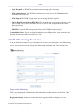
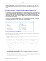
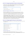
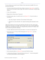
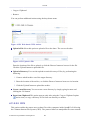
4.2.6.1 Configuring the NAT
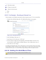
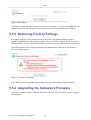
Click the 'NAT' link under the 'Firewall' menu item. The 'NAT' screen appears.
Figure 4.22 Network Address Translation
Before configuring NAT/NAPT rules, you must first enter the additional public IP addresses
obtained from your ISP as your NAT IP addresses, in the 'NAT IP Addresses Pool' section.
Note: The primary IP address used by the WAN device for dynamic NAPT should not be
added to this table.
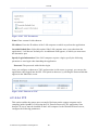
To add a NAT IP address, perform the following:
1. Click the 'New IP Address' link. The 'Edit Item' screen appears.
© 1998-2010 Jungo Software Technologies Ltd.
47
Services
Figure 4.23 Edit Item
2. To add a single public address, select the 'IP Address' option from the 'Network Object
Type' drop-down menu, and enter the IP in the fields that appear.
Figure 4.24 Edit Item
To add a range of public IP addresses, select the 'IP Range' option and enter the available
IP range.
Figure 4.25 Edit Item
3. Click 'OK' to save the settings. The new IP addresses are displayed in the 'NAT IP
Addresses Pool' section.
Figure 4.26 NAT IP Addresses
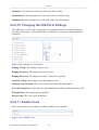
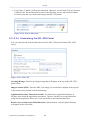
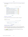
To add a new NAT/NAPT rule, click the 'New Entry' link in the 'NAT/NAPT Rule Sets'
section of the 'NAT' screen. The 'Add NAT/NAPT Rule' screen appears.
© 1998-2010 Jungo Software Technologies Ltd.
48
Services
Figure 4.27 Add NAT/NAPT Rule
Matching Use this section to define characteristics of the packets matching the rule.
• Source Address The source address of packets sent or received by OpenRG. Use this dropdown menu to specify a LAN computer or a group of LAN computers on which you would
like to apply the rule. Select an address or a name from the list to apply the rule on the
corresponding host, or 'Any' to apply the rule on all OpenRG's LAN hosts. If you would
like to add a new address, select the 'User Defined' option in the drop-down menu. This will
commence a sequence that will add a new Network Object, representing the new host.
• Destination Address The destination address of packets sent or received by OpenRG. This
address can be configured in the same manner as the source address. For example, use this
drop-down menu to specify an IP address of a remote application server (such as a security
server), which requires that the incoming packets have a specific IP address (e.g., one of
those defined in your NAT IP address pool).
• Protocol You may also specify a traffic protocol. Selecting the 'Show All Services' option
from the drop-down menu expands the list of available protocols. Select a protocol or add a
new one using the 'User Defined' option. This will commence a sequence that will add a new
Service, representing the protocol.
© 1998-2010 Jungo Software Technologies Ltd.
49
Services
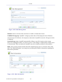
Operation Use this section to define the operation that will be applied on the IP addresses
matching the criteria defined above. The operations available are NAT or NAPT. Selecting
each from the drop-down menu refreshes the screen accordingly.
• NAT Addresses
Figure 4.28 Add NAT Rule
This drop-down menu displays all of your available NAT addresses/ranges, from which you
can select an entry. If you would like to add a single address or a sub-range from the given
pool/range, select the 'User Defined' option in the drop-down menu. This will commence a
sequence that will add a new Network Object, representing the new host.
• NAPT Address
Figure 4.29 Add NAPT Rule
This drop-down menu displays all of your available NAPT addresses/ranges, from which
you can select an entry. If you would like to add a single address or a sub-range from the
given pool/range, select the 'User Defined' option from the drop-down menu. This will
commence a sequence that will add a new Network Object, representing the new host.
Note, however, that in this case the network object may only be an IP address, as NAPT is
port-specific.
• NAPT Ports Specify the port(s) for the IP address into which the original IP address will be
translated. Enter a single port or select 'Range' in the drop-down menu. The screen refreshes,
enabling you to enter a range of ports.
Figure 4.30 Add NAPT Rule
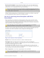
Logging Monitor the rule.
© 1998-2010 Jungo Software Technologies Ltd.
50
Services
• Log Packets Matched by This Rule Select this check box to log the first packet from a
connection that was matched by this rule.
Schedule By default, the rule will always be active. However, you can define time segments
during which the rule may be active, by selecting 'User Defined' from the 'Schedule' drop-down
menu. If more than one scheduler rule is defined, the 'Schedule' drop-down menu will allow
you to choose between the available rules. To learn how to configure scheduler rules, refer to
the 'Defining Scheduler Rules' section of the OpenRG Administrator Manual.
4.2.6.2 NAT/NAPT Configuration Examples
This section demonstrates the NAT/NAPT usage and capabilities, by creating several
rules and observing their implementation. In the following examples, the LAN IP address
range is 192.168.1.5 through 192.168.1.25. The NAT addresses are 192.168.71.12 through
192.168.71.20, and they have been entered to the NAT address pool as described earlier.
In the 'NAT' screen, click the 'New Entry' link in the 'NAT/NAPT Rule Sets' section. The 'Add
NAT/NAPT Rule' screen appears.
Figure 4.31 Add NAT/NAPT Rule
Create the following NAT/NAPT rules:
© 1998-2010 Jungo Software Technologies Ltd.
51
Services
1. Translate the address 192.168.1.10 to 192.168.71.12. In this example, LAN addresses
(192.168.1.X) are not defined yet, therefore do not appear as drop-down menu options, and
network objects must be created in order to represent them.
a. Select 'User Defined' in the 'Source Address' drop-down menu. The 'Edit Network
Object' screen appears.
Figure 4.32 Edit Network Object
b. Click 'New Entry'. The 'Edit Item' screen appears.
Figure 4.33 Edit Item
c. Select 'IP Address' in the 'Network Object Type' drop-down menu, and enter
192.168.1.10.
d. Click 'OK' to save the settings.
e. Click 'OK' in the 'Edit Network Object' screen.
f. Back in the 'Add NAT/NAPT Rule' screen, select 192.168.1.10 from the 'Source'
drop-down menu.
g. From the 'NAT Addresses' drop-down menu, select the '192.168.71.12' option. The
screen refreshes, adding this address as a NAT IP address.
h. Click 'OK' to save the settings.
© 1998-2010 Jungo Software Technologies Ltd.
52
Services
The NAT rule is displayed in the 'NAT' screen.
Figure 4.34 NAT/NAPT Rule Sets
This rule translates one LAN IP address to one NAT IP address, meaning that this LAN
computer will have WAN access at any time. The status is therefore set to "Active".
2. Translate the range 192.168.1.11-192.168.1.15 to 192.168.71.12-192.168.71.15. Define
this NAT rule in the same manner depicted above, with the exception of selecting 'IP
Range' (instead of 'IP Address') as the network object type. Since both ranges are not
predefined (no such drop-down menu options), network objects must be created in order
to represent them, using the 'User Defined' option in the 'Source' and 'NAT' drop-down
menus respectively. The created rule is displayed in the 'NAT' screen.
Figure 4.35 NAT/NAPT Rule Sets
This rule translates five new LAN IP addresses to four NAT IP addresses, which would
normally mean that only four of the five LAN computers may have WAN access at the
same time. However, note that the NAT address 192.168.71.12 is already in use by the
first rule. OpenRG will therefore allow these five LAN computers to use only the three
remaining IP addresses ending with 71.13, 71.14 and 71.15. The status is therefore set to
"Active".
3. Translate the range 192.168.1.21-192.168.1.25 to 192.168.71.13-192.168.71.14. Define
this NAT rule in the same manner depicted above. The following attention message is
displayed.
Figure 4.36 Attention
Click 'OK'. The rule is displayed in the 'NAT' screen.
© 1998-2010 Jungo Software Technologies Ltd.
53
Services
Figure 4.37 NAT/NAPT Rule Sets
This rule translates five new LAN IP addresses to two NAT IP addresses, both of which
are already in use by the second rule. OpenRG is therefore unable to resolve this situation
and the rule's status is set to "Error". Notice that had this rule been defined as the second
rule, all three rules would be valid. This is because the NAT address 192.168.71.15 would
still be available for rule number 1. This can easily be amended: you can use the green
arrow icons to move a rule entry up or down, changing its priority respectively. Click this
rule's
action icon once. All rules will now be set to "Active".
Figure 4.38 NAT/NAPT Rule Sets
Note: The first rule now maps five LAN addresses to one NAT address. OpenRG
subtracts all previously used NAT addresses, requested by previous rules, from the
requested NAT addresses of the current rule. The requested range of addresses does
not determine how many will be available; the number of available addresses is
determined by previous rules configuration and order. Rules will appear as "Active"
even if they only have one usable NAT address.
4. Translate the address 192.168.1.5 to 192.168.71.16 ports 1024-1050. Define this NAPT
rule in the same manner depicted above, with the following exception:
a. Select the 'NAPT' option in the 'Operation' section drop-down menu. The screen
refreshes.
© 1998-2010 Jungo Software Technologies Ltd.
54
Services
Figure 4.39 Add NAPT Rule
b. Add a NAPT address by selecting the 'User Defined' option.
c. Enter 1024-1050 as the range of ports in the 'NAPT Ports' section.
d. Click 'OK' to save the settings.
The rule is displayed in the 'NAT' screen.
Figure 4.40 NAT/NAPT Rule Sets
This rule translates a LAN IP address to a NAT IP address with specific ports. Its status is
set to "Active".
5. Translate the address 192.168.1.6 to 192.168.71.16 ports 1024-1100. Define this NAPT
rule in the same manner depicted above. The rule is displayed in the 'NAT' screen.
© 1998-2010 Jungo Software Technologies Ltd.
55
Services
Figure 4.41 NAT/NAPT Rule Sets
This rule translates a LAN IP address to a NAT IP address with ports 1024-1100.
However, only ports 1051-1100 will be used for this LAN computer, as ports 1024-1050
are already in use by the preceding rule. The status is set to "Active".
Every new NAT/NAPT rule is verified in relation to preceding rules. Rules are prioritized
according to the order in which they are defined. As long as at least one unused IP address (or
port) is available, the rule will be accepted. However, as seen in the examples above, not all
addresses in the range defined may be available for computers in that rule; some may already
be in use by other rules. OpenRG automatically calculates the relationships between rules,
narrowing down the address ranges if needed, and thus provides great flexibility for user input.
The verification performed by OpenRG is as follows:
• NAT rule – Verifies whether the IP address is already in use by another NAT/NAPT rule.
• NAPT rule
1. Verifies whether the port is already in use by another NAPT rule activated on the same
IP address.
2. Verifies whether the IP address is already in use by another NAT rule.
4.3 Managing Your Bandwidth with
Quality of Service
Network-based applications and traffic are growing at a high rate, producing an ever-increasing
demand for bandwidth and network capacity. For obvious reasons, bandwidth and capacity
cannot be expanded infinitely, requiring that bandwidth-demanding services be delivered over
existing infrastructure, without incurring additional, expansive investments.
The next logical means of ensuring optimal use of existing resources are Quality of Service
(QoS) mechanisms for congestion management and avoidance. Quality of Service refers to
© 1998-2010 Jungo Software Technologies Ltd.
56
Services
the capability of a network device to provide better service to selected network traffic. This
is achieved by shaping the traffic and processing higher priority traffic before lower priority
traffic.
As Quality of Service is dependent on the "weakest link in the chain", failure of but a single
component along the data path to assure priority packet transmission can easily cause a VoIP
call or a Video on Demand (VoD) broadcast to fail miserably. QoS must therefore obviously be
addressed end-to-end.
Figure 4.42 End-to-end QoS Challenge Areas
The following are the potential bottleneck areas that need be taken into consideration when
implementing an end-to-end QoS-enabled service.
• The Local Area Network LANs have finite bandwidth, and are typically limited to 100
Mbps. When given the chance, some applications will consume all available network
bandwidth. In business networks, a large number of network-attached devices can lead to
congestion. The need for QoS mechanisms is more apparent in wireless LANs (802.11a/
b/g), where bandwidth is even more limited (typically no more than 20 Mbps on 802.11g
networks).
• The Broadband Router All network traffic passes through and is processed by the
broadband router. It is therefore a natural focal point for QoS implementation. Lack of
sufficient buffer space, memory or processing power, and poor integration among system
components can result in highly undesirable real-time service performance. The only way
to assure high quality of service is the use of proper and tightly-integrated router operating
system software and applications, which can most effectively handle multiple real-time
services simultaneously.
• The Broadband Connection Typically the most significant bottleneck of the network, this
is where the high speed LAN meets limited broadband bandwidth. Special QoS mechanisms
must be built into routers to ensure that this sudden drop in connectivity speed is taken into
account when prioritizing and transmitting real-time service-related data packets.
© 1998-2010 Jungo Software Technologies Ltd.
57
Services
• The Internet Internet routers typically have a limited amount of memory and bandwidth
available to them, so that congestions may easily occur when links are over-utilized, and
routers attempt to queue packets and schedule them for retransmission. One must also
consider the fact that while Internet backbone routers take some prioritization into account
when making routing decisions, all data packets are treated equally under congested
conditions.
The following figure depicts OpenRG's QoS role and architecture in a network. Many of the
terms it contains will become familiar as you read on.
Figure 4.43 OpenRG's QoS Architecture
4.3.1 Selecting a QoS Profile
The 'General' screen provides a Quality of Service "wizard", with which you can configure
your QoS parameters according to predefined profiles, with just a few clicks. A chosen QoS
profile will automatically define QoS rules, which you can view and edit in the rest of the QoS
tab screens, described later.
Note: Selecting a QoS profile will cause all previous QoS configuration settings to be
permanently lost.
Click the QoS tab under 'Services'. The 'General' screen appears with the 'Overview' link being
selected.
© 1998-2010 Jungo Software Technologies Ltd.
58
Services
Figure 4.44 General
WAN Devices Bandwidth (Rx/Tx) Before selecting the QoS profile that mostly suits your
needs, select your bandwidth from this drop-down menu. If you do not see an appropriate
entry, select 'User Defined', and enter your Tx and Rx bandwidths manually.
• Tx Bandwidth This parameter defines the gateway's outbound transmission rate. Enter your
Tx bandwidth in Kbits per second.
• Rx Bandwidth This parameter defines the gateway's Internet traffic reception rate. Enter
your Rx bandwidth in Kbits per second.
Note: By default, these parameters are set to 0 Kbps, which means that the bandwidth
has not been limited on OpenRG. Entering inaccurate Tx/Rx values will cause incorrect
behavior of the QoS module. It is important to set these values as accurately as possible.
If you wish to restore the default bandwidth settings, select 'Unlimited' from the drop-down
menu, and click 'Apply'. Note that you can also set the desired bandwidth on the WAN (or any
other) device in the 'Traffic Shaping' screen (to learn how to do so, refer to Section 4.3.4.1).
QoS Profiles Select the profile that mostly suits your bandwidth usage. Each profile entry
displays a quote describing what the profile is best used for, and the QoS priority levels granted
to each bandwidth consumer in this profile.
• Default – No QoS profile, however the device is limited by the requested bandwidth, if
specified.
© 1998-2010 Jungo Software Technologies Ltd.
59
Services
• P2P User – Peer-to-peer and file sharing applications will receive priority.
• Triple Play User – VoIP and video streaming will receive priority.
• Home Worker – VPN and browsing will receive priority.
• Gamer – Game-related traffic will receive priority.
• Priority By Host – This entry provides the option to configure which computer in your LAN
will receive the highest priority and which the lowest. If you have additional computers, they
will receive medium priority.
High Priority Host Enter the host name or IP address of the computer to which you
would like to grant the highest bandwidth priority.
Low Priority Host Enter the host name or IP address of the computer to which you
would like to grant the lowest bandwidth priority.
4.3.2 Viewing Your Bandwidth Utilization
The 'Internet Connection Utilization' screen provides detailed real-time information regarding
the usage of your Internet connection's bandwidth. At any time, you can view an up-to-date
bandwidth usage report on both the application and computer level.
4.3.2.1 Application View
The 'Utilization by Application' table displays the following information fields. You can sort
the table according to these fields (ascending or descending), by clicking the fields' names.
Note that you can stop the screen's refreshing by using the 'Automatic Refresh Off' button at
the bottom of the screen.
Figure 4.45 Utilization by Application
Application A list of categories of applications that are currently using the bandwidth. This
section may also display user-defined or unknown applications that had not been identified by
OpenRG as belonging to one of the pre-defined categories. In this case, their names will appear
as links, which you can click to view their details.
© 1998-2010 Jungo Software Technologies Ltd.
60
Services
Protocol The application's network protocol.
Port The port through which traffic is transferred.
Tx Throughput The transmission bit rate in kilo-bits per second.
Rx Throughput The reception bit rate in kilo-bits per second.
To view the applications that underlie the displayed categories, click the 'Advanced' button.
Figure 4.46 Utilization by Application – Advanced View
In this view, you can click each application's name to view its details, particularly which LAN
computer is running it.
Figure 4.47 A Specific Application
4.3.2.2 Computer View
The 'Utilization by Computer' table displays the sum of bandwidth used by each LAN
computer. The fields displayed are the computer's IP address and the Tx and Rx throughput.
© 1998-2010 Jungo Software Technologies Ltd.
61
Services
Figure 4.48 Utilization by Computer
Click a computer's IP address to view the bandwidth-consuming applications running on that
computer.
Figure 4.49 A Specific Computer
In this example, computer 192.168.1.6 is running the applications "Web Server" and
"Incoming Mail". This screen provides a combined computer and application view, by
displaying a computer-specific application table.
4.3.3 Defining Traffic Priority Rules
Traffic Priority allows you to manage and avoid traffic congestion by defining inbound and
outbound priority rules for each device on your gateway. These rules determine the priority that
packets, traveling through the device, will receive. QoS parameters (DSCP marking and packet
priority) are set per packet, on an application basis. You can set QoS parameters using flexible
rules, according to the following parameters:
• Source/destination IP address, MAC address or host name
• Device
• Source/destination ports
• Limit the rule for specific days and hours
OpenRG supports two priority marking methods for packet prioritization:
© 1998-2010 Jungo Software Technologies Ltd.
62
Services
• DSCP (refer to Section 4.3.5).
• 802.1p Priority (refer to Section 4.3.6).
The matching of packets by rules is connection-based, known as Stateful Packet Inspection
(SPI), using the same connection-tracking mechanism used by OpenRG's firewall. Once a
packet matches a rule, all subsequent packets with the same attributes receive the same QoS
parameters, both inbound and outbound. A packet can match more than one rule. Therefore:
• The first class rule has precedence over all other class rules (scanning is stopped once the
first rule is reached).
• The first traffic-priority (classless) rule has precedence over all other traffic-priority rules.
• There is no prevention of a traffic-priority rule conflicting with a class rule. In this case, the
priority and DSCP setting of the class rule (if given) will take precedence.
Connection-based QoS also allows inheriting QoS parameters by some of the applications that
open subsequent connections. For instance, you can define QoS rules on SIP, and the rules will
apply to both control and data ports (even if the data ports are unknown). This feature applies
to all applications that have ALG in the firewall, such as:
• SIP
• MSN Messenger/Windows Messenger
• TFTP
• FTP
• MGCP
• H.323
• Port Triggering applications (refer to Section 4.2.4)
• PPTP
• IPSec
To set traffic priority rules:
1. Under the 'QoS' menu item, click 'Traffic Priority'. The 'Traffic Priority' screen appears
(see Figure 4.50). This screen is divided into two identical sections, one for 'QoS input
rules' and the other for 'QoS output rules', which are for prioritizing inbound and outbound
traffic, respectively. Each section lists all the gateway devices on which rules can be set.
You can set rules on all devices at once, using the 'All devices' entry.
© 1998-2010 Jungo Software Technologies Ltd.
63
Services
Figure 4.50 Traffic Priority
2. After choosing the traffic direction and the device on which to set the rule, click the
appropriate 'New Entry' link. The 'Add Traffic Priority Rule' screen appears.
Figure 4.51 Add Traffic Priority Rule
This screen is divided into two main sections, 'Matching' and 'Operation', which are for
defining the operation to be executed when matching conditions apply.
Matching Use this section to define characteristics of the packets matching the rule.
• Source Address The source address of packets sent or received by OpenRG. Use
this drop-down menu to specify the computer or group of computers on which you
would like to apply the rule. Select an address or a name from the list to apply the rule
on the corresponding host, or 'Any' to apply the rule on any host trying to send data.
If you would like to add a new address, select the 'User Defined' option in the dropdown menu. This will commence a sequence that will add a new Network Object,
representing the new host.
© 1998-2010 Jungo Software Technologies Ltd.
64
Services
• Destination Address The destination address of packets sent or received by OpenRG.
This address can be configured in the same manner as the source address. For example,
use this drop-down menu to specify an IP address of a remote application server (such
as a security server), which requires that the incoming packets have a specific IP address
(e.g., one of those defined in your NAT IP address pool).
• Protocol You may also specify a traffic protocol. Selecting the 'Show All Services'
option from the drop-down menu expands the list of available protocols. Select a
protocol or add a new one using the 'User Defined' option. This will commence a
sequence that will add a new Service, representing the protocol.
Using a protocol requires observing the relationship between a client and a server, in
order to distinguish between the source and destination ports. For example, let's assume
you have an FTP server in your LAN, serving clients inquiring from the WAN. You
want to apply a QoS rule on incoming packets from any port on the WAN (clients)
trying to access FTP port 21 (your server), and the same for outgoing packets from port
21 trying to access any port on the WAN. Therefore, you must set the following Traffic
Priority rules:
• In the 'Matching' section of 'QoS Input Rules', select 'FTP' from the 'Protocol' dropdown menu. The 'TCP Any -> 21' setting appears under 'Ports'.
• Define a priority in the 'Operation' section.
• Click 'OK' to save the settings.
• Define a QoS output rule in the same way as the input rule.
• DSCP Select this check box to display two DSCP fields, which enable you to specify
a hexadecimal DSCP value and its mask assigned to the packets matching the priority
rule. For more information, refer to Section 4.3.5.
• Priority Select this check box to display a drop-down menu, in which you can select a
priority level assigned to the packets matching the priority rule.
• Device Select this check box to display a drop-down menu, in which you can select a
network device on which the packet-rule matching will be performed. This option is
relevant in case you have previously selected the 'All Devices' option in the 'Traffic
Priority' screen (see Figure 4.50).
• Length Select this check box if you would like to specify the length of packets, or the
length of their data portion.
Note: The following two options are applicable only if the Fastpath feature is
disabled in the 'Routing' menu item under 'System'. Depending on your gateway's
model, the feature's name may appear as 'Software Acceleration' or 'Hardware
Acceleration'.
© 1998-2010 Jungo Software Technologies Ltd.
65
Services
• Connection Duration Select this check box to apply the priority rule only on
connections which are open for a certain time period. This option is especially useful if
you would like to accelerate your Web browsing by lowering the speed of concurrently
running download jobs, or vice versa. After selecting the check box, choose whether the
duration of connections matching the rule should be greater or less than the time that
you specify in the adjacent field.
Figure 4.52 Connection Duration
For example, if you define the connection duration as less than 10 seconds, you will
notice acceleration of your Web browsing and small file downloads, but slowing down
of your large file downloads. The reason for this is that when a connection passes the
specified time limit (as in case of a large file download), its priority is lowered, thereby
giving more priority to shorter connections.
• Connection Size Select this check box to apply the priority rule only on connections
matching a certain data size limit. This option is best used along with the 'Connection
Duration' option, enabling you to fine-tune the gateway's traffic priority mechanism
according to your needs. After selecting the check box, choose whether the connection's
data size should be greater or less than the number of kilobytes that you specify in the
adjacent field.
Figure 4.53 Connection Size
For example, if you define the connection size as less than 400 kilobytes, you will notice
acceleration of Web browsing, and lowering of your file download speed. The reason
for this is that when a connection exceeds the specified data size limit, its priority is
lowered, thereby giving more priority to connections with a smaller data size.
Operation Perform the following operation/s on packets that match the priority rule.
• Set DSCP Select this check box if you would like to change the DSCP value on packets
matching the rule, prior to routing them further. The screen refreshes (see Figure 4.54),
enabling you to enter the hexadecimal DSCP value in its respective field that appears.
Figure 4.54 Set DSCP Rule
• Set Priority Select this check box if you would like to change a priority of the packets
matching the rule. The screen refreshes (see Figure 4.55), enabling you to select
between one of eight priority levels, zero being the lowest and seven the highest. Each
priority level is assigned a default queue number, where Queue 0 has the lowest priority.
OpenRG's QoS supports up to eight queues.
© 1998-2010 Jungo Software Technologies Ltd.
66
Services
Figure 4.55 Set Priority with Queueing
The matching between a priority level and a queue number can be edited in the '802.1p
Settings' screen (for more information, refer to Section 4.3.6).
• Apply QoS on Select whether to apply QoS on a connection or just the first packet.
When applying on a connection, the data transfer session will be handled using Stateful
Packet Inspection (SPI). This means that other packets matching this rule will be
automatically allowed to access, and the same QoS scheme will be applied to them.
Logging Monitor the rule.
• Log Packets Matched by This Rule Select this check box to log the first packet from a
connection that was matched by this rule.
Schedule By default, the rule will always be active. However, you can define time
segments during which the rule may be active, by selecting 'User Defined' from the
'Schedule' drop-down menu. If more than one scheduler rule is defined, the 'Schedule'
drop-down menu will allow you to choose between the available rules. To learn how to
configure scheduler rules, refer to the 'Defining Scheduler Rules' section of the OpenRG
Administrator Manual.
3. Click 'OK' to save the settings.
The order of the rules' appearance represents both the order in which they were defined and the
sequence by which they will be applied. You may change this order after your rules are already
defined (without having to delete and then re-add them), by using the
action icon .
action icon and
Figure 4.56 Move Up and Move Down Action Icons
4.3.4 Avoiding Congestion with Traffic Shaping
Traffic Shaping is the solution for managing and avoiding congestion where a high speed LAN
meets limited broadband bandwidth. In the scenario of a 100 Mbps Ethernet LAN with a 100
Mbps WAN interface gateway, the gateway may have to communicate with the ISP using a
modem with a bandwidth of 2Mbps. This typical configuration makes the modem, having no
QoS module, the bottleneck.
© 1998-2010 Jungo Software Technologies Ltd.
67
Services
Instead of sending traffic as fast as it is received, OpenRG's QoS algorithms perform traffic
shaping, limiting the bandwidth of the gateway, thus artificially forcing it to become the
bottleneck. A traffic shaper is essentially a regulated queue that accepts uneven and/or bursty
flows of packets and transmits them in a steady, predictable stream so that the network is not
overwhelmed with traffic. While Traffic Priority allows basic prioritization of packets, Traffic
Shaping provides more sophisticated definitions, such as:
• Bandwidth limit for each device
• Bandwidth limit for classes of rules
• Prioritization policy
• TCP serialization on a device
Additionally, you can define QoS traffic shaping rules for a default device. These rules will be
used on a device that has no definitions of its own. This enables the definition of QoS rules on
Default WAN, for example, and their maintenance even if the PPP or bridge device over the
WAN is removed.
4.3.4.1 Shaping the Traffic of a Device
To shape the traffic of a device, perform the following:
1. Click 'Traffic Shaping' under the QoS tab in the 'Services' screen. The 'Traffic Shaping'
screen appears.
Figure 4.57 Traffic Shaping
2. Click the 'New Entry' link. The 'Add Device Traffic Shaping' screen appears (see
Figure 4.58).
3. Select the device for which you would like to shape the traffic. The drop-down menu
includes all your gateway's devices, and you can select either a specific device for which to
shape the traffic, or 'Any Device' to add a traffic class to all devices. In this example, select
the WAN Ethernet option.
© 1998-2010 Jungo Software Technologies Ltd.
68
Services
Figure 4.58 Add Device Traffic Shaping
If you would like to configure OpenRG's LAN traffic transmission/reception rate,
select the relevant LAN device. If you would like to apply the settings on all LAN
devices, select the 'Default LAN Device' entry.
4. Click 'OK'. The 'Edit Device Traffic Shaping' screen appears.
Figure 4.59 Edit Device Traffic Shaping
5. Configure the following fields:
Tx Bandwidth This parameter limits the gateway's bandwidth transmission rate. The
purpose is to limit the bandwidth of the WAN device to that of the weakest outbound link,
for instance, the DSL speed provided by the ISP. This forces OpenRG to be the network
bottleneck, where sophisticated QoS prioritization can be performed. If the device's
bandwidth is not limited correctly, the bottleneck will be in an unknown router or modem
on the network path, rendering OpenRG's QoS useless.
TCP Serialization You can enable TCP Serialization in its drop-down menu, either
for active voice calls only or for all traffic. The screen will refresh, adding a 'Maximum
Delay' field (see Figure 4.60). This function allows you to define the maximal allowed
transmission time frame (in milliseconds) of a single packet. Any packet that requires
a longer time to be transmitted, will be fragmented to smaller sections. This avoids
© 1998-2010 Jungo Software Technologies Ltd.
69
Services
transmission of large, bursty packets that may cause delay or jitter for real-time traffic such
as VoIP. If you insert a delay value in milliseconds, the delay in number of bytes will be
automatically updated on refresh.
Figure 4.60 TCP Serialization – Maximum Delay
Queue Policy Tx traffic queueing can be based on a traffic class (see the following
explanations) or on the pre-defined priority levels (refer to Section 4.3.3). Note that when
it is based on a traffic class, the class's bandwidth requirements will be met regardless
of the priority, and only excess bandwidth will be given to traffic with a higher priority.
However, when unlimited bandwidth is selected for the Tx traffic, the queue policy can
only be based on the pre-defined priority levels.
4.3.4.2 Creating a Traffic Shaping Class
The bandwidth of a device can be divided in order to reserve constant portions of bandwidth to
predefined traffic types. Such a portion is known as a Traffic Shaping Class. When not used by
its predefined traffic type, or owner (for example VoIP), the bandwidth will be available to all
other traffic. However when needed, the entire class is reserved solely for its owner.
Moreover, you can limit the maximum bandwidth that a class can use even if the entire
bandwidth is available. When a traffic class is first defined for a specific traffic type, two
classes are created. The second class is the 'Default Class', which is responsible for all the
packets that do not match the defined traffic class, or any other classes that may be defined
on the device. You can also define wildcard devices, such as all WAN devices. This can be
viewed in the 'Class Statistics' screen (see Figure 4.70).
To define a new traffic shaping class, perform the following:
1. In the 'Edit Device Traffic Shaping' screen (see Figure 4.59), click the 'New Entry' link in
the 'Tx Traffic Shaping' section. The 'Add Shaping Class' screen appears.
Figure 4.61 Add Shaping Class
2. Name the new class and click 'OK' to save the settings, e.g. Class A.
3. Back in the 'Edit Device Traffic Shaping' screen, click the class name to edit the traffic
class. Alternatively, click its
© 1998-2010 Jungo Software Technologies Ltd.
action icon . The 'Edit Shaping Class' screen appears.
70
Services
Figure 4.62 Edit Shaping Class
4. Configure the following fields:
Name The name of the class.
Class Priority The class can be granted one of eight priority levels, zero being the
highest and seven the lowest (note the obversion when compared to the rules priority
levels). This level sets the priority of a class in comparison to other classes on the device.
Bandwidth The reserved transmission bandwidth in kilo-bits per second. You can limit
the maximum allowed bandwidth by selecting the 'Specify' option in the drop-down menu.
The screen will refresh, adding another Kbits/s field.
Figure 4.63 Specify Maximum Bandwidth
Policy The class policy determines the policy of routing packets inside the class. Select
one of the four options:
• Priority Priority queuing utilizes multiple queues, so that traffic is distributed among
queues based on priority. This priority is defined according to packet's priority, which
can be defined explicitly, by a DSCP value (refer to Section 4.3.5), or by a 802.1p value
(refer to Section 4.3.6).
• FIFO The "First In, First Out" priority queue. This queue ignores any previouslymarked priority that packets may have.
• Fairness The fairness algorithm ensures no starvation by granting all packets a certain
level of priority.
• RED The Random Early Detection algorithm utilizes statistical methods to drop packets
in a "probabilistic" way before queues overflow. Dropping packets in this way slows a
source down enough to keep the queue steady and reduces the number of packets that
would be lost when a queue overflows and a host is transmitting at a high rate.
• WRR Weighted Round Robin utilizes a process scheduling function that prioritizes
traffic according to the pre-defined 'Weight' parameter of a traffic's class. This level of
prioritizing provides more flexibility in distributing bandwidth between traffic types, by
defining additional classes within a parent class.
© 1998-2010 Jungo Software Technologies Ltd.
71
Services
Schedule By default, the class will always be active. However, you can configure
scheduler rules in order to define time segments during which the class may be active. To
learn how to configure scheduler rules, refer to the 'Defining Scheduler Rules' section of
the OpenRG Administrator Manual.
4.3.4.3 Setting an Incoming Traffic Policy
When shaping the traffic for a device, you must also determine a policy for incoming traffic. In
the 'Edit Device Traffic Shaping' screen (see Figure 4.59), configure the following fields in the
'Rx Traffic Policing' section:
Rx Bandwidth This parameter limits the device's bandwidth reception rate. In this example,
the purpose is to limit the bandwidth that the WAN device can receive from the ISP.
Queue Policy Similar to Tx traffic, Rx traffic queueing can be based on a traffic class or on
strict priority (unless unlimited bandwidth is selected). By default, however, the queue policy
is set to Policer, which is a relatively simple method of bandwidth control. With the policer
option, you can dedicate a portion of the bandwidth to a certain traffic type. This portion will
always remain available to its traffic type, even when not in use. This is a simpler method, as
prioriy is not used at all.
When selecting a class-based queue policy, you must define an Rx Traffic Policy Class, which
is identical to defining a Tx Traffic Shaping Class, described earlier. However if you select the
policer as your queue policy, defining a policing class is even simpler, as it lacks the priority
setup.
To define an Rx traffic policy class, perform the following:
1. In the 'Edit Device Traffic Shaping' screen (see Figure 4.59), click the 'New Entry' link in
the 'Rx Traffic Policing' section. The 'Add Policing Class' screen appears.
Figure 4.64 Add Policing Class
2. Name the new class and click 'OK' to save the settings, e.g. Class B.
3. Back in the 'Edit Device Traffic Shaping' screen, click the class name to edit the traffic
class. Alternatively, click its
© 1998-2010 Jungo Software Technologies Ltd.
action icon . The 'Edit Policing Class' screen appears.
72
Services
Figure 4.65 Edit Policing Class
Configure the following fields:
Name The name of the class.
Bandwidth The reserved reception bandwidth in kilo-bits per second. You can limit the
maximum allowed bandwidth by selecting the 'Specify' option in the combo box. The screen
refreshes, adding yet another Kbps field.
Figure 4.66 Specify Maximum Bandwidth
Schedule By default, the class will always be active. However, you can configure scheduler
rules in order to define time segments during which the class may be active. To learn how
to configure scheduler rules, refer to the 'Defining Scheduler Rules' section of the OpenRG
Administrator Manual.
4.3.5 Prioritizing Traffic with DSCP
In order to understand what is Differentiated Services Code Point (DSCP), one must first be
familiarized with the Differentiated Services model. Differentiated Services (Diffserv) is a
Class of Service (CoS) model that enhances best-effort Internet services by differentiating
traffic by users, service requirements and other criteria. Packets are specifically marked,
allowing network nodes to provide different levels of service, as appropriate for voice calls,
video playback or other delay-sensitive applications, via priority queuing or bandwidth
allocation, or by choosing dedicated routes for specific traffic flows.
Diffserv defines a field in IP packet headers referred to as DSCP. Hosts or routers passing
traffic to a Diffserv-enabled network will typically mark each transmitted packet with an
appropriate DSCP. The DSCP markings are used by Diffserv network routers to appropriately
classify packets and to apply particular queue handling or scheduling behavior. OpenRG
provides a table of predefined DSCP values, which are mapped to 802.1p priority marking
method (refer to Section 4.3.6).
You can edit or delete any of the existing DSCP setting, as well as add new entries.
1. Under the QoS menu item, click 'DSCP Settings'. The following screen appears.
© 1998-2010 Jungo Software Technologies Ltd.
73
Services
Figure 4.67 DSCP--Traffic Priority Matching
Each DSCP value is assigned a default queue number as a part of its 802.1p priority
settings. OpenRG's QoS supports up to eight queues, where Queue 0 has the lowest
priority.
2.
To edit an existing entry, click its
action icon . To add a new entry, click the 'New
Entry' link. In both cases, the 'Edit DSCP Settings' screen appears.
Figure 4.68 Edit DSCP Settings
3. Configure the following fields:
DSCP Value (hex) Enter a hexadecimal number that will serve as the DSCP value.
802.1p Priority Select a 802.1p priority level from the drop-down menu (each priority
level is mapped to low/medium/high priority).
4. Click 'OK' to save the settings.
Note: The DSCP value overriding the priority of incoming packets with an unassigned
value (priority 0, assumed to be a no-priority-set) is "0x0".
4.3.6 Configuring 802.1p Priority Values
The IEEE 802.1p priority marking method is a standard for prioritizing network traffic at the
data link/MAC sub-layer. 802.1p traffic is simply classified and sent to the destination, with
© 1998-2010 Jungo Software Technologies Ltd.
74
Services
no bandwidth reservations established. The 802.1p header includes a 3-bit prioritization field,
which allows packets to be grouped into eight levels of priority (0-7), where level 7 is the
highest one. In addition, OpenRG maps these eight levels to priority queues, where Queue 0
has the lowest priority.
OpenRG's QoS supports up to eight queues. By default, the higher the level and queue values,
the more priority they receive. Therefore, the more critical the traffic is, the higher priority
level and queue number it should receive. To change the mapping between a priority value and
a queue value, perform the following:
1. Under the 'QoS' menu item, click '802.1p Settings'. The following screen appears.
Figure 4.69 Traffic Queuing in 802.1p Settings
2. From the corresponding drop-down menu, select a desired value.
3. Click 'OK' to save the settings.
4.3.7 Viewing Traffic Statistics
OpenRG provides you with accurate, real-time information on the traffic moving through
your defined device classes. For example, the amount of packets sent, dropped or delayed, are
just a few of the parameters that you can monitor per each shaping class. To view your class
statistics, click 'Class Statistics' under the QoS menu item. The following screen appears.
Figure 4.70 Class Statistics
Note that class statistics will only be available after defining at least one class (otherwise the
screen will not present any information).
© 1998-2010 Jungo Software Technologies Ltd.
75
Services
4.3.8 Example: Providing Priority to a Voice
Stream
In order to gain a better understanding of the Quality of Service concept, this section presents
a scenario where the WAN bandwidth is shaped to provide priority to a voice stream. When
shared by a Voice over IP (VoIP) conversation and a file transfer, the bandwidth will normally
be exploited by the file transfer, reducing the quality of the conversation or even casuing it to
disconnect. With QoS, the VoIP conversation, which is a real-time session, receives the priority
it requires, maintaining a high level of voice quality.
4.3.8.1 Hardware Requirements
• A gateway runnning OpenRG
• Two IP phones
• A LAN computer running an FTP client, containing a large file (100MB)
• A WAN computer running an FTP server
4.3.8.2 Physical Setup
1. Connect an IP phone and the LAN computer to OpenRG's LAN ports.
2. Connect OpenRG's WAN port to your network. The second IP phone and the WAN
computer should be available on the WAN.
Figure 4.71 Physical Setup
4.3.8.3 Scenario Configuration
1. Configure OpenRG and all other devices with the static IPs described in Figure 4.71.
2. Define a global service for the VoIP stream over a SIP protocol:
© 1998-2010 Jungo Software Technologies Ltd.
76
Services
Figure 4.73 Edit Service Server Ports
a. In OpenRG's WBM, click the 'Protocols' icon in the 'Advanced' screen, and then click
the 'New Entry' link. The 'Edit Service' screen appears (see Figure 4.72).
b. Enter "SIP" as the service name. You may also add a description for the service.
Figure 4.72 Edit Service
c. Click the 'New Server Ports' link. The 'Edit Service Server Ports' screen appears (see
Figure 4.73).
d. From the drop-down menu, select the UDP protocol. The screen will refresh.
e. Verify that "Any" is selected from the 'Source Ports' drop-down menu.
f. From the 'Destination Ports' drop-down menu, select "Single". The screen will refresh
again.
g. Enter 5060 as the single destination port.
h. Click 'OK' to save the settings.
3. Limit the bandwidth of OpenRG's WAN device:
a. Under the 'QoS' menu item, click 'Traffic Shaping'. The following screen appears.
© 1998-2010 Jungo Software Technologies Ltd.
77
Services
Figure 4.74 Traffic Shaping
b. Click the 'New Entry' link, and select 'All Devices' from the drop-down menu.
Figure 4.75 Add Device Traffic Shaping
c. Click 'OK'. The 'Edit Device Traffic Shaping' screen appears.
Figure 4.76 Edit Device Traffic Shaping
d. In the Tx Bandwidth drop-down menu, select 'Specify', and enter 200 Kbps in the
field that appears.
e. In the Rx Bandwidth drop-down menu, select 'Specify', and enter 200 Kbps in the
field that appears.
f. Verify that TCP Serialization is disabled.
4. Configure a QoS class for the Tx and Rx VoIP streams. Perform this procedure twice:
once for Tx Traffic Shaping and once for Rx Traffic Policing.
© 1998-2010 Jungo Software Technologies Ltd.
78
Services
a. Click the 'New Entry' link in the Tx/Rx traffic shaping section of the 'Edit Device
Traffic Shaping' screen. The 'Add Class' screen appears (see Figure 4.77).
b. Name the new class "VoIP Tx/Rx", and click 'OK' to save the settings.
Figure 4.77 Add Shaping Class
c. Uncheck the entry in the Class ID column to disable the class at this point (see
Figure 4.78).
Figure 4.78 Shaping Classes – Uncheck the Class ID
d.
Click the class name to edit the shaping class. Alternatively, click its
The 'Edit Class' screen appears (see Figure 4.79).
e. Enter 100 Kbps in the Reserved Tx/Rx Bandwidth field.
f. Leave all other fields at their default values.
Figure 4.79 Edit Shaping Class
© 1998-2010 Jungo Software Technologies Ltd.
79
action icon .
Services
g. Click 'OK' to save the settings.
h. Click 'OK' once more in the 'Edit Device Traffic Shaping' screen to save all settings.
5. Define and associate class rules:
a. Click 'Traffic Priority' under the 'QoS' tab in the 'Services' screen. The 'Traffic
Priority' screen appears.
Figure 4.80 Traffic Priority
b. Click the 'New Entry' link of the 'WAN Ethernet Rules' under the 'QoS Output Rules'
section. The 'Add Traffic Priority Rule' screen appears.
Figure 4.81 Add Traffic Priority Rule
c. In the 'Matching' section, select 'Show All Services' from the 'Protocol' dropdown menu, and then select "SIP". The screen will refresh displaying the protocol
parameters (see Figure 4.82).
© 1998-2010 Jungo Software Technologies Ltd.
80
Services
d. In the 'Operation' section, check the 'Set Rx/Tx Class Name' check boxes, and select
'VoIP Rx/Tx' from the drop-down menus that appear.
Figure 4.82 Add Traffic Priority Rule – SIP Protocol
e. Leave all other fields at their default values, and click 'OK' to save the settings.
4.3.8.3.1 Implementing the WRR Class Policy in VoIP's QoS
The WRR class policy enables you to fine-tune your Tx traffic priority settings. For instance,
in a scenario where you utilize more than one VoIP protocol (for example, SIP and H.323),
you can further prioritize VoIP's Tx traffic. In the following example, the SIP protocol is given
preference over H.323. Therefore, you may assign 70% of the VoIP bandwidth to the SIPbased traffic, and 30% to the H.323-based traffic. To enable the WRR class policy, perform the
following:
1. In the 'Edit Device Traffic Shaping' screen (see Figure 4.78), click the 'VoIP Tx' link. The
'Edit Shaping Class' screen appears (see Figure 4.79).
2. From the 'Policy' drop-down menu, select the WRR option. The screen refreshes, and a
new section called 'Subclasses' is added.
© 1998-2010 Jungo Software Technologies Ltd.
81
Services
Figure 4.83 Subclasses Section in Edit Shaping Class
3. In the 'Subclasses' section, click either the 'New Entry' link or the
'Add Shaping Class' screen appears.
action icon . The
Figure 4.84 Add Shaping Class
This time, the screen contains two fields: 'Name' and 'Weight'.
4. In the 'Name' field, enter 'SIP' for the name of a VoIP's subclass assigned to the SIP-based
traffic.
5. In the 'Weight' field, enter a numeric value that correlates with the amount of bandwidth
you want to grant to the subclass. In the current example, the subclass is granted 70% of
VoIP's Tx traffic. Therefore, enter 7 in the 'Weight' field.
Note: The class weight range is between 1 and 10000.
6. Click 'OK' to save the settings.
Repeat the same procedure for creating the H.323 subclass of VoIP. However, in the 'Weight'
field enter 3 that corresponds to 30% of the VoIP bandwidth you want to assign to the H.323
subclass.
Note: When you activate the WRR class policy, it is not mandatory to define an Rx
shaping class and its priority rules.
Once the subclasses are created, define the priority rules for the subclasses, as follows:
© 1998-2010 Jungo Software Technologies Ltd.
82
Services
1. Click 'Traffic Priority' under the 'QoS' tab in the 'Services' screen. The 'Traffic Priority'
screen appears (see Figure 4.80).
2. Click the 'New Entry' link of the 'WAN Ethernet Rules' under the 'QoS Output Rules'
section. The 'Add Traffic Priority Rule' screen appears (see Figure 4.81).
3. In the 'Matching' section, select 'Show All Services' in the 'Protocol' drop-down menu, and
then select 'SIP'. The screen refreshes displaying the protocol parameters.
Note: You can also define the 'SIP' protocol manually, as described in
Section 4.3.8.3.
4. In the 'Operation' section, check the 'Set Tx Class Name' check box, and select 'SIP' in the
drop-down menu that appears.
Figure 4.85 Add Traffic Priority Rule # SIP Protocol
5. Leave all other fields at their default values, and click 'OK' to save the settings.
Repeat the same procedure for defining a priority rule for the H.323 subclass. The only
difference is that you should select the 'H.323 Call Signaling' value for the protocol settings,
and 'H.323' for the Tx class name.
4.3.8.4 Running the Scenario
1. Initiate a direct call (using the SIP protocol) from one IP phone to the other. For VoIP
configuration, refer to Section 4.5. Verify that the conversation can be conducted clearly
and adequately.
2. Initiate an FTP file upload from the LAN computer to the WAN computer. This can be
done using the Windows command line. Use the hash command to utilize the pound
© 1998-2010 Jungo Software Technologies Ltd.
83
Services
sign process indicator before starting the file transfer. As soon as the upload commences,
your ability to transmit voice will be lost—the WAN party will not be able to hear you.
The upload, on the other hand, will be proceeding rapidly, taking up all of your transmit
bandwidth (see Figure 4.86).
Figure 4.86 FTP Process
3. Activate QoS to restore the voice transmission:
a. Under the 'QoS' menu item, click 'Traffic Shaping'. The 'Traffic Shaping' screen
appears.
Figure 4.87 Traffic Shaping
b. Click the Device name, in this case 'All devices', and check both entries in the Class
ID column to enable the classes (see Figure 4.88).
Figure 4.88 Shaping Classes – Check the Class ID
© 1998-2010 Jungo Software Technologies Ltd.
84
Services
c. Click 'OK' to save the settings.
The transmission capability will be restored, as most of the bandwidth will now be
reserved for the VoIP stream. The file upload rate, on the other hand, will obviously slow
down.
Note: Some IP phones and ATA devices are preconfigured to send DSCP-marked
data. OpenRG will handle such data with QoS priority, even if a QoS class is not
configured for the VoIP stream. To run the above scenario successfully, you must
first disable DSCP marking on such devices.
4.3.9 Example: Providing Priority to an IPTV
Stream
This section presents a scenario in which the WAN bandwidth is shaped to provide priority to
a media broadcast (for example, an IPTV stream). When your bandwidth is shared between
a media stream and data transfer, a greater portion of it will normally be used by the data
transfer, reducing the quality of the media broadcast or even disrupting it. With the help of
OpenRG's Traffic Shaping feature, the media stream receives the priority it requires, thereby
maintaining its quality. This scenario is based on the following real-life case.
Assume that you have a 100 Mbps Ethernet LAN with a 100 Mbps WAN interface router. The
router communicates with the ISP network via a modem that has a 2Mbps bandwidth, and does
not have a QoS module. When OpenRG's Traffic Shaping feature is disabled, the router sends
traffic to the modem as fast as it is received from the LAN host. This typical configuration
makes the modem a bottleneck. However, if you enable Traffic Shaping on the router, it will
limit the router's bandwidth, artificially forcing it to be the bottleneck. This configuration
creates a regulated traffic queue that enables the router to accept uneven and bursty flows of
packets and transmit them in a steady, predictable stream.
4.3.9.1 Simulating Limited Bandwidth and IPTV Setup
As a first step, simulate limited bandwidth by reducing OpenRG's Rx/Tx bandwidth in the
following way:
1. Under the 'Services' tab, click 'QoS'. The following screen appears.
© 1998-2010 Jungo Software Technologies Ltd.
85
Services
Figure 4.89 General
2. From the 'WAN Devices Bandwidth(Rx/Tx)' drop-down menu, select 5000/256 Kbps.
3. Click 'OK' to save the settings.
To simulate an IPTV setup, use the Video LAN Client (VLC) application. VLC supports
both Client and Server modes. In its server mode, VLC can be used on a WAN host as the
broadcaster, which sends a video stream to a multicast group. In its client mode, VLC can
be used as a media player on a LAN host. VLC uses a multicast IP address range between
224.0.0.0 – 239.255.255.255. It can be installed both on Linux and Windows computers. You
can download VLC from http://www.videolan.org/vlc/download-windows.html.
To configure the VLC server, perform the following:
1. In VLC's 'File' menu, select 'Wizard'. The following screen appears.
© 1998-2010 Jungo Software Technologies Ltd.
86
Services
Figure 4.90 Streaming/Transcoding Wizard
2. Select the 'Stream to Network' radio button and click 'Next'. The 'Input' screen appears.
Figure 4.91 Input
3. Verify that the 'Select a stream' radio button is selected, and click 'Choose'. The following
dialog box appears.
© 1998-2010 Jungo Software Technologies Ltd.
87
Services
Figure 4.92 File Selection Dialog Box
4. Click 'Browse', and select the video file you would like to stream.
5. Click 'OK', and then 'Next'. The 'Streaming' screen appears.
Figure 4.93 Streaming
6. Under 'Streaming method', select 'RTP Multicast'.
7. In the 'Destination' field, enter the multicast group IP address (between 224.0.0.22 –
224.0.0.102).
© 1998-2010 Jungo Software Technologies Ltd.
88
Services
8. Click 'Next'. The 'Encapsulation format' screen appears.
Figure 4.94 Encapsulation format
9. Verify that the 'MPEG TS' radio button is selected, and click 'Next'. The 'Additional
streaming options' screen appears.
Figure 4.95 Additional streaming options
10. Set the 'Time-To-Live (TTL)' parameter to be greater than five (depends on the number of
network hops).
© 1998-2010 Jungo Software Technologies Ltd.
89
Services
11. Click 'Finish' to exit the wizard.
To configure the VLC client, perform the following:
1. From the 'File' menu, select 'Open Network Stream'. The following screen appears.
Figure 4.96 Network
2. Select the 'UDP/RTP Multicast' radio button, and enter the multicast group address (as
defined in the VLC server) in the 'Address' text box that opens.
3. Click 'OK' to save the settings.
While watching the video on the LAN PC, load the network by downloading a large file from
the WAN using FTP. Run the FTP's hash command to visualize the file download speed. The
video and sound stream quality will noticeably degrade.
4.3.9.2 Using QoS for Improving the Streaming Quality
To improve the media stream quality, perform the following:
1. Designate a protocol and a specific port number for the media stream:
a. In OpenRG's WBM, click the 'Advanced' tab and select 'Protocols'. The 'Protocols'
screen appears.
© 1998-2010 Jungo Software Technologies Ltd.
90
Services
Figure 4.97 Protocols
This screen displays a list of preset and user-defined applications and common port
settings. You may add new protocols to support new applications or edit existing ones
according to your needs. For more information, refer to the 'Protocols' section of the
OpenRG Administrator Manual.
b. Click the 'New Entry' link. The 'Edit Service' screen appears.
Figure 4.98 Edit Service
c. Change the default service name to 'IPTV', and click the 'New Server Ports' link. The
'Edit Service Server Ports' screen appears.
© 1998-2010 Jungo Software Technologies Ltd.
91
Services
Figure 4.99 Edit Service Server Ports
d. From the 'Protocol' drop-down menu, select 'UDP'. The screen refreshes, changing to
the following.
Figure 4.100 Edit Service Server Ports – UDP
e. From the 'Source Ports' drop-down menu, select 'Any'.
f. From the 'Destination Ports' drop-down menu, select 'Single' and enter port 1234 (the
default port to which VLC sends the media stream).
g. Click 'OK' to save the settings.
2. Create a traffic shaping class ID:
a. Under the 'Services' tab, click the 'QoS' menu item and select 'Traffic Shaping'. The
'Traffic Shaping' screen appears, displaying the bandwidth you have set on the default
WAN device.
Figure 4.101 Traffic Shaping
© 1998-2010 Jungo Software Technologies Ltd.
92
Services
b.
Click the 'Default WAN device' link or its
Shaping' screen appears.
action icon . The 'Edit Device Traffic
Figure 4.102 Edit Device Traffic Shaping
c. Under 'Class ID', click the 'New Entry' link. The 'Add Policing Class' screen appears.
Figure 4.103 Add Policing Class
d. Change the default class name to 'IPTV', and click 'OK'. The 'Edit Device Traffic
Shaping' screen appears with the IPTV class entry displayed in the 'Rx Traffic
Policing' section.
Figure 4.104 Edit Device Traffic Shaping – IPTV Class
e.
Click the 'IPTV' link or its
© 1998-2010 Jungo Software Technologies Ltd.
action icon . The 'Edit Policing Class' screen appears.
93
Services
Figure 4.105 Edit Policing Class – IPTV
f. In the 'Reserved' field of the 'Bandwidth' parameter, enter 3000 and click 'OK'. You
will be redirected back to the 'Edit Device Traffic Shaping' screen (see Figure 4.104).
The bandwidth reserved for the IPTV will be displayed in its respective field.
3. As the last step, define a priority rule for the incoming traffic:
a. Under the 'QoS' menu item, click 'Traffic Priority'. The corresponding screen appears.
Figure 4.106 Traffic Priority
b. In the 'Qos Input Rules' section, click the 'New Entry' link of the 'WAN Ethernet
Rules' item. The 'Add Traffic Priority Rule' screen appears.
© 1998-2010 Jungo Software Technologies Ltd.
94
Services
Figure 4.107 Add Traffic Priority Rule
c. From the 'Protocol' drop-down menu, select 'IPTV' (if it is not displayed, select 'Show
All Services'). The screen refreshes, displaying the IPTV protocol entry.
Figure 4.108 Add Traffic Priority Rule – IPTV Protocol
d. Under 'Operation', select the 'Set Rx Class Name' check box. The screen refreshes,
displaying the IPTV Rx class.
Figure 4.109 Add Traffic Priority Rule – IPTV Rx Class
e. Click 'OK' to save the settings.
Restart the video stream on the LAN while downloading a large file from the WAN using
FTP. You will notice that the video stream has no disruptions, while the file download speed
slows down slightly.
© 1998-2010 Jungo Software Technologies Ltd.
95
Services
4.4 Sharing Your Media with the Home
Network
OpenRG's Media Sharing solution enables you to share and stream media files from a storage
device connected to OpenRG. You can access the shared media files with either a networkaware Consumer Electronic (CE) device, as described in Section 4.4.2, or from a LAN PC with
an installed media rendering software, as described in Section 4.4.3. Both methods utilize a
Universal Plug and Play (UPnP) media renderer.
4.4.1 Configuring the Media Sharing Service
Configure OpenRG's media sharing service by clicking its menu item under the 'Services' tab.
The 'Media Sharing' screen appears.
Figure 4.110 Media Sharing
The 'Media Sharing' screen contains the following options:
Share Music, Pictures and Video on My Local Network By default, this option is
selected. To disable media sharing, deselect this option, and click 'Apply'.
Automatically Share Media in All Folders By default, this option is selected, causing
all partitions and folders on the storage device to become shared automatically. OpenRG
automatically scans the storage device for media files, and displays folders containing such
files in the 'Local Folders' section of this screen. To disable the automatic sharing and manually
share a specific partition or folder, perform the following:
1. Deselect the 'Automatically Share Media in All Folders' check box and click 'Apply'. The
screen refreshes.
© 1998-2010 Jungo Software Technologies Ltd.
96
Services
Figure 4.111 Manual Folder Sharing Mode
The 'Status' field changes to 'No Shares', and a new section appears, enabling you to create
and manage a list of manually shared partitions and their folders.
2. Click the 'Add Folder' link, or the
action icon . The 'Folder Settings' screen appears.
Figure 4.112 Folder Settings
3. In the 'Folder' field, enter the exact path (for example, A/Music, where 'A' is a partition's
letter, and 'Music' is a folder on this partition).
Note: The partition's letter cannot be changed. OpenRG automatically assigns a
letter to a partition, once the storage device is connected. For more information, refer
to Section 4.7.2.
4. In the 'Title' field, enter a descriptive title for the folder (for example, 'Pop Music'). Note
that entering this information is mandatory.
5. Click 'OK' to save the settings. The 'Media Sharing' screen appears, displaying the shared
partition. If necessary, repeat the same procedure to share additional partitions and their
folders.
At any time, you can edit the partition or folder sharing settings by clicking its
action icon .
In addition, you can remove a partition or a folder from the shares list by clicking its
icon .
© 1998-2010 Jungo Software Technologies Ltd.
97
action
Services
Note: In case of changing the sharing settings, click the 'Rescan' button in the WBM's
'Media Sharing' screen before trying to access the shared media remotely. Clicking the
'Rescan' button updates the media database with the current shared media content and its
path. The more disk space the media files occupy, the longer the scanning process may
take.
OpenRG adds the MEDIASRV.DB file to all the writable partitions it identifies on the storage
device. This is an index file that the media server uses to access the media files on the disk.
Therefore, do not delete this file.
When adding or removing a media file via OpenRG's file server, the media database is updated
automatically. However, if other file management utilities are used (for example, FTP) to add
or remove a file, click the 'Rescan' button to update the database with the changes. Otherwise,
OpenRG will update the database during its periodic scanning of the shared media, which is
performed once every 24 hours.
4.4.2 Streaming Your Media to a TV via a Media
Client Device
OpenRG enables you to share and stream media files (music, pictures, and video) from its
storage device to a TV set, over a media client device. The following sections explain how to
connect this device to a TV set and the gateway, as well as how to stream the shared media
content.
4.4.2.1 Connecting a Media Client
A modern media client device includes a network-aware Universal Plug and Play (UPnP)
media renderer. Typically, this device has an RCA or coaxial connection to the TV set, as well
as a LAN socket and/or a wireless LAN interface for connecting to the gateway.
© 1998-2010 Jungo Software Technologies Ltd.
98
Services
Figure 4.113 Media Client Device and Television Connection
1. Connect your TV set to the media client device according to the instructions provided with
the device. Make sure you select the correct AV input on the TV set.
2. Connect the media client device to an available Ethernet port on your gateway.
Note: If your media client device has a wireless capability, it can connect to
OpenRG without cables. However, since media usage requires streaming high
volumes of traffic, wireless use is recommended only if the media client device
supports the 802.11n protocol.
4.4.2.2 Viewing and Streaming Media Files
Reception of OpenRG's media server broadcast by the media client device is automatic,
requiring no further configuration.
1. Turn on the media client device. The following images represent the D-Link
MediaLounge™ media client menu, displayed on the TV set (connected to the device).
© 1998-2010 Jungo Software Technologies Ltd.
99
Services
Figure 4.114 MediaLounge Main Screen
2. Use the device's remote control to select 'My Media'. The path letter of the OpenRG share
(which contains your disk content) appears.
Figure 4.115 Your Share on OpenRG
3. Select the share. The share's content is displayed.
© 1998-2010 Jungo Software Technologies Ltd.
100
Services
Figure 4.116 Media Folders on a Share
Note: MediaLounge displays the same directory hierarchies as on the storage device.
4. Select a folder, for example "photos". The folder's content is displayed.
Figure 4.117 Media Files in the Shared Folder
5. Select a photo to display.
© 1998-2010 Jungo Software Technologies Ltd.
101
Services
Figure 4.118 Displaying a Photograph
In the same method, you can stream music and video files from your disk to your television.
4.4.3 Accessing the Shared Media from a LAN
Computer
In this section, you will learn how to access your media content from any LAN computer, on
which a media rendering client application is installed. One of such applications is XBMC
Media Center. The following example utilizes XBMC to demonstrate how to access the
shared media via a LAN computer.
After installing this application on your computer, perform the following:
1. Launch XBMC. Its main screen appears.
© 1998-2010 Jungo Software Technologies Ltd.
102
Services
Figure 4.119 XBMC Main Screen
2. Select the type of media you would like to view by clicking the corresponding link (either
'Videos', 'Music', or 'Pictures'). For example, select 'Music'. The following screen appears.
Figure 4.120 Add source
3. To obtain access to the desired media files, you must first define a path to the shared
directory in which the files are stored. To do so, perform the following:
a. Select 'Add source' (see Figure 4.120), and click the 'Browse' button in the next
screen. The 'Browse for new share' dialog box appears.
© 1998-2010 Jungo Software Technologies Ltd.
103
Services
Figure 4.121 Browse for new share
b. Select the 'UPnP Devices' option. The following screen appears.
Figure 4.122 OpenRG's Media Server Link
The 'Jungo Media Server' link provides access to the storage device connected to
OpenRG.
c. Click this link. After scanning your storage device for media content, XBMC displays
the shared partition(s) on which it has detected media files.
© 1998-2010 Jungo Software Technologies Ltd.
104
Services
Figure 4.123 Shared Partition Containing Media Files
d. Click the partition's link. The shared media directories are displayed.
Figure 4.124 Media Directories on a Share
Note that XBMC displays the same directory hierarchies as on the storage device.
e. Select a directory in which the desired media files are located.
f. To save the path to the media directory, click 'OK' in the directory's 'Browse for new
share' dialog box, and confirm in the next dialog box. This will create a shortcut
© 1998-2010 Jungo Software Technologies Ltd.
105
Services
(named 'Jungo Media Server') to the selected directory, enabling you to access the
shared media from XBMC.
Figure 4.125 Jungo Media Server Shortcut
4. Click the 'Jungo Media Server' shortcut. A list of media files stored in the selected
directory will be displayed.
Figure 4.126 Media Files in the Shared Directory
Note: In case the media directory specified in the path contains subdirectories, they
will be displayed when clicking the 'Jungo Media Server' link. Select the desired
subdirectory to display the files it contains.
5. Click a file's link to start playing it with XBMC.
© 1998-2010 Jungo Software Technologies Ltd.
106
Services
Similarly, perform the above procedure to define paths for the other types of media you would
like to access.
4.5 Utilizing Telephony on Your
Gateway
OpenRG's Analog Telephone Adapter (ATA) Voice solution enables you to connect multiple
phones over a single broadband connection, providing the benefits and quality of digital Voice
Over IP (VoIP). This solution enables you to place and receive calls over the Internet using a
standard telephone set connected to OpenRG.
This section assumes that you have already connected your telephone equipment to the
gateway, as described in the 'Connecting a Telephone' section of the OpenRG Quick Start
Guide.
OpenRG provides two types of independent telephone usages: external calling—when the
gateway is provisioned with SIP telephone lines, and internal communication within the home
network.
Note: OpenRG's voice functionality is based on the Asterisk VoIP stack.
4.5.1 Configuring Your Telephone Line
Services
Before using your telephone, configure the services available on its line according to your
preferences. In the 'Line Settings' screen under the 'Voice' menu item, click the line's
icon . In the 'Services' section, select the services you would like to activate.
Figure 4.127 Line Settings – Services
Enable Call Waiting Select this check box to enable the Call Waiting feature.
© 1998-2010 Jungo Software Technologies Ltd.
107
action
Services
Enable 3-Way Calling Select this check box to allow all forms of three-way conversations.
When this option is disabled you will not be able to place a call on hold, transfer a call or
engage in a call conference.
Enable Message Waiting Indication Select this check box to play a special stutter tone
whenever you receive a voice message.
Enable Do Not Disturb Select this check box to prevent calls from reaching your line. The
caller will hear a busy tone. This feature can also be enabled or disabled by dialing *78 or *79
respectively.
Enable Call Forwarding Always Select this check box to forward incoming calls to
another telephone number. The screen refreshes, displaying a field for entering the alternate
number.
Figure 4.128 Enable Call Forwarding Always
This feature can also be enabled or disabled by dialing *72 (and the alternate number) or *73
respectively.
Enable Call Forwarding on Busy Select this check box to forward incoming calls to
another telephone number when the line is busy. The screen refreshes, displaying a field for
entering the alternate number.
Figure 4.129 Enable Call Forwarding on Busy
This feature can also be enabled or disabled by dialing *90 (and the alternate number) or *91
respectively.
Enable Call Forwarding on No Answer Select this check box to forward incoming calls
to another telephone number if the call is not answered within a specific timeframe. The screen
refreshes, displaying a field for entering the alternate number, and a field for determining the
timeframe to ring before the call is forwarded.
Figure 4.130 Enable Call Forwarding on No Answer
This feature can also be enabled or disabled by dialing *92 (and the alternate number) or *93
respectively.
© 1998-2010 Jungo Software Technologies Ltd.
108
Services
4.5.2 Operating Your Telephone
Following are several guidelines that will help you perform basic telephne operations.
• Placing a Call
1. Pick up the handset of the phone (off-hook).
2. Dial the extension number (both '#' and the number) or the remote party's number. To
have the call sent out immediately, you may dial '#'.
• Answering a Waiting Call
When the Call Waiting feature is enabled, you may receive a call while engaged in another
call. When such call arrives, you will hear a call waiting tone.
1. To answer a waiting call, press 'Flash'.
2. 'Flash' may be used to switch back and forth between calls.
• Blind Transfer
To transfer an existing call (B) to a third party (C) without consultation, perform the
following:
1. Press 'Flash'. Party B will now be placed on hold, and you will hear a dial tone.
2. Dial *98. You should hear three short beeps followed by a dial tone.
3. Dial party C's number. You should hear a high toned beep followed by two low toned
beeps, followed by a dial tone. B is now initiating a call to C. You may now dial a new
call or hang up the phone.
• Call Transfer With Consultation
To transfer an existing call (B) to a third party (C), perform the following:
1. Press 'Flash' on the phone. Party B will now be placed on hold, and you will hear a dial
tone.
2. Dial party C's number or a pre-configured speed dial number followed by '#' (you can
engage in conversation).
3. To complete the transfer, place the phone's handset on-hook.
• 3-Way Conference
To extend an existing call (B) into a 3-way conference by bringing in an additional party (C),
perform the following:
1. Press 'Flash' on the phone. Party B will now be placed on hold and you will hear a dial
tone.
© 1998-2010 Jungo Software Technologies Ltd.
109
Services
2. Dial party C's number or a pre-configured speed dial number followed by '#' (you can
engage in conversation).
3. Press 'Flash' to join both C and B to a single conference.
4. When you place the phone's handset on-hook, party B and party C will remain in
conversation.
4.5.3 Configuring and Using Speed Dial
You can assign speed dial numbers to parties that you call frequently. Speed dial entries can be
configured according to three types of destinations:
• Proxy speed dial entry This entry is intended for calling users that have an account with
your telephone service provider.
1. Click the 'Speed Dial' link under the 'Voice' menu item. The 'Speed Dial' screen appears.
Figure 4.131 Speed Dial
2. Click the 'New Entry' link to add a new speed dial entry. The 'Speed Dial Settings'
screen appears.
Figure 4.132 Speed Dial – via Proxy
3. Enter the following parameters:
Speed Dial A shortcut number that you will dial to call this party.
© 1998-2010 Jungo Software Technologies Ltd.
110
Services
Destination The entry's destination, in this case a proxy.
User ID Specify the remote party's user ID (most commonly the telephone number).
4. Click 'OK' to save the settings.
• Local line speed dial entry This entry is intended for calling the other lines in your home
network (local lines connected to your gateway).
1. In the 'Speed Dial' screen (see Figure 4.131), click 'New Entry' and select the 'Local
Line' option from the drop-down menu. The screen refreshes.
Figure 4.133 Speed Dial - Local Line
2. Enter the following parameters:
Speed Dial A shortcut number that you will dial to call this party.
Destination The entry's destination, in this case a local line.
Line The drop-down menu displays your pre-defined local lines. Select a destination
line.
3. Click 'OK' to save the settings.
• Direct call speed dial entry This entry is intended for calling any telephone number over
the Internet.
1. In the 'Speed Dial' screen (see Figure 4.131), click 'New Entry' and select the 'Direct
Call' option from the drop-down menu. The screen refreshes.
© 1998-2010 Jungo Software Technologies Ltd.
111
Services
Figure 4.134 Speed Dial – Direct Call
2. Enter the following parameters:
Speed Dial A shortcut number that you will dial to call this party.
Destination The entry's destination, in this case a direct call.
User ID Specify the remote party's user ID (most commonly the telephone number).
IP Address or Host Name Specify the IP address or host name of the remote party's
SIP client.
3. Click 'OK' to save the settings.
4.5.4 Sending a Fax
You can send and receive faxes over an OpenRG telephone line. Simply connect a fax machine
to an active FXS telephone port on the gateway, and send the fax as you would from any other
telephone.
Note: This feature is currently available on the Broadcom 96358 platform only.
Although you can send and receive faxes with the default settings, OpenRG enables you to
configure the fax transmission method and codec. In the 'Line Settings' screen under the 'Voice'
menu item, click the line's
following options.
action icon . In the 'Fax Transmission' section, configure the
Figure 4.135 Line Settings – Fax Transmission
© 1998-2010 Jungo Software Technologies Ltd.
112
Services
Fax Transmission Method The method used to switch to a codec that supports
transmission of fax messages. Select a method from the drop-down menu:
• None Selecting this option deactivates this feature. The codec agreed upon by both sides
of the conversation (refer to Section 4.5.8.6) , which does not necessarily support fax
transmission, will not change. Therefore fax trasmission may fail.
• T.38 Auto Fax tones will be converted into T.38 packets and then transmitted. This digital
mode is the most reliable fax transmission method.
• Pass-Through Auto A conversation will begin with the codec agreed upon by both sides. If
fax tones become present, OpenRG will switch to the codec selected in the next drop-down
menu, which supports fax transmission.
• Pass-Through Force Select this option to ensure that OpenRG begins all conversations with
the fax-supporting codec selected in the next drop-down menu.
Fax Pass-Through Codec This option is only visible if a Pass-Through method is selected.
Select either the u-Law or A-Law codec supporting fax transmission.
4.5.5 Customizing Your Phone Service with a
Numbering Plan
A numbering plan is a set of preconfigured shortcut numbers that when dialed, perform preset
actions. The caller can dynamically activate or deactivate certain actions, using the telephone
keypad. For example, the caller can activate call forwarding by dialing a prefix and the number
to which to forward the call.
In the 'Line Settings' screen under the 'Voice' menu item, click the line's
'Numbering Plan' section, configure the following options.
Figure 4.136 Line Settings – Numbering Plan
© 1998-2010 Jungo Software Technologies Ltd.
113
action icon . In the
Services
Minimum Number of Digits The minimum number of digits that must be dialed in order
for OpenRG to send out the call.
Maximum Number of Digits The maximum number of digits that can be dialed in order
for OpenRG to send out the call.
Inter-Digit Timer Specifies the duration (in milliseconds) of allowed inactivity between
dialed digits. If the limit is exceeded, the dialing process times out and a warning tone is
played. When you work with a proxy or gatekeeper, the number you have dialed before the
dialing process has timed out is sent to the proxy/gatekeeper as the user ID to be called. This is
useful for calling a remote party without creating a speed dial entry (assuming the remote party
is registered with the proxy/gatekeeper).
The 'Prefixes' table displays the configured actions, containing the following parameters.
• Prefix Range The digits, or range of digits, constituting the prefix that activates the action.
Note that a range is limited to ten digits, as only the last digit can be changed. For example,
*72, 1800, 1800-1809, etc.
• Maximum Number of Digits The maximum number of digits that can be dialed when
activating this action (including the prefix range).
• Facility Action The action that will be activated.
You can edit or delete the prefix entries defined in the table, using the action icons. To add a
new entry, perform the following:
1. Click the 'New Entry' link. The 'Edit Prefix' screen appears.
Figure 4.137 Edit Prefix
2. Enter a prefix range.
3. Determine the minimum and maximum number of digits to be dialed when activating a
rule.
4. Enter the number of digits to remove from the dialed number. This is useful for removing
unwanted dialed numbers, such as the digit 9 for external access.
© 1998-2010 Jungo Software Technologies Ltd.
114
Services
5. Select the facility action to perform. Among activating and deactivating the "Call
Forwarding" and "Do Not Disturb" features described earlier, a new "VoIP Call" action
is available. Use this action to override the generic numbering plan rules. For example,
if you limit callers to dial 3-digit numbers only (by setting the generic maximum number
of digits to 3), but would like to enable them to dial 1-800 numbers, enter "1800" as the
prefix range, and specify the maximum number of digits that 1-800 numbers may have.
6. Click 'OK' to save the settings.
4.5.6 Using Distinctive Ring
If your gateway's Digital Signal Processing (DSP) module supports the Distinctive Ring
service (available on some SIP servers), you can enrich your telephone line functionality by:
• Creating additional numbers for your line, and assigning a distinctive ring pattern to each of
them. This is useful, for example, if you want to distinguish between incoming calls.
• Assigning a distinctive ring pattern to the incoming calls, by matching the caller ID to a
specific ring tone. By doing so, you can recognize the caller's identity before answering the
call.
Note: The availability of the service implementations depends on the SIP service
provider.
To activate the Distinctive Ring service, you must first create a SIP account on a server that
supports this feature. Examples of such SIP servers are Broadsoft (http://www.broadsoft.com)
and Broadvoice (http://www.broadvoice.com). After registering and configuring your SIP
account, enter the SIP account settings and the proxy parameters in OpenRG's 'Line Settings'
screen, as described in the 'Connecting a Telephone' section of the OpenRG Quick Start Guide.
4.5.7 Ensuring Constant Connectivity with
Failover
Normally, telephones connected to the FXS ports are provided with lines by a SIP service over
the Internet. If your gateway also includes an FXO port, you can connect it to your telephone
wall outlet (PSTN). In case your gateway's connection to the SIP service is disrupted, your
phones can be automatically switched to the FXO port connected to the PSTN line, thereby
ensuring that you always have telephone connectivity. This capability is called PSTN Failover.
Note: This feature is currently available only on the Broadcom 96358 platform.
You can both send and receive PSTN phone calls via FXO. When a call arrives from PSTN,
all telephones connected to the FXS ports will ring simultaneously, unless the 'Do Not Disturb'
feature is enabled on some of them. When using an FXS line on which call waiting is enabled,
you will hear a call waiting tone whenever a call arrives from PSTN.
© 1998-2010 Jungo Software Technologies Ltd.
115
Services
Connect your gateway's FXO port to the telephone wall outlet. In the 'Line Settings' screen
under the 'Voice' menu item, click the line's
action icon . In the 'PSTN Failover' section of
the external line settings screen, define under which circumstances the line failover will occur,
by selecting the corresponding check boxes.
Figure 4.138 Line Settings – PSTN Failover
Failover if SIP "OPTIONS" Keep-Alive Check Failed Select this check box to enable
the line failover in case the SIP server stops responding to keep-alive messages sent by
OpenRG's PBX.
Failover if WAN Connectivity Check Failed Select this check box to enable the line
failover in case OpenRG has detected that there is no WAN connectivity.
Failover if Registration Failed Select this check box to enable the line failover in case the
line's registration on the SIP server has failed.
4.5.8 Advanced Telephony Options
This section provides advanced options intended for a technician or a system administrator.
4.5.8.1 Determining DTMF Tones
DTMFs are the tones generated by your telephone's keypad, which are used by different
telephone servers (for example, for selecting an option from a menu). If required, you can
change the transmission method of these tones. In the 'Line Settings' screen under the 'Voice'
menu item, click the line's
the following options.
action icon . In the 'Advanced SIP Settings' section, configure
Figure 4.139 Line Settings – Advanced SIP Settings
DTMF Transmission Method Select a transmission method from the drop-down menu:
• Inband The DTMF keypad tones are sent within the voice stream.
• Out-of-Band Always (RFC2833) The DTMF keypad tones are represented by the keypad
number and are sent as separate packets. This is a more reliable transmission method.
© 1998-2010 Jungo Software Technologies Ltd.
116
Services
• Q.931 Keypad The DTMF keypad tones are sent using Q.931 messages.
• H.245 Alphanumeric The DTMF keypad tones are sent using an H.245 alphanumeric
Information Element (IE).
• H.245 Signal The DTMF keypad tones are sent using an H.245 signal IE.
• Out-of-Band by Negotiation (RFC2833) This method allows negotiation with the remote
party. DTMF tones will be sent either in-band or out-of-band, depending on the remote
party's preference.
• SIP INFO A special SIP message that includes the DTMF event description.
Compatibility Mode If you are using Broadsoft as your SIP provider, select its mode from
this drop-down menu. Otherwise, leave as "Off".
4.5.8.2 Monitoring Your Lines
You can monitor the status of your telephone lines in one convenient place—the 'Monitoring'
screen. Access this screen by clicking the 'Monitoring' link under the 'Voice' menu item.
Figure 4.140 Monitoring
This screen displays all available lines and information on their statuses in real-time. These
statuses include:
Registration Status Indicates whether the line is registered with a telephony service.
© 1998-2010 Jungo Software Technologies Ltd.
117
Services
Call State The current state of the line—either "Idle" or "In call".
When a call is in progress, additional call statistics appear, such as the number of packets sent/
received/lost, interarrival jitter, and more.
Figure 4.141 Call Statistics
4.5.8.3 Changing the Signaling Protocol
The signaling protocols available with OpenRG are Session Initiation Protocol (SIP), H.323,
and Radvision's MGCP. To change your signaling protocol according to your telephone service
provider, click the 'Advanced' link under the 'Voice' menu item. In the 'Signaling Protocol'
section, select a protocol in the drop-down menu. A different subset of parameters will become
visible with each signaling protocol choice. To apply the protocol change you must click
'Apply' (at the bottom of the 'Advanced' screen).
4.5.8.3.1 SIP
Figure 4.142 SIP Signaling Protocol
Local SIP Port The port on OpenRG that listens to SIP requests from the proxy. By default,
port 5060 is used for SIP signaling of phones connected to the gateway. A common problem
occurs when using a SIP agent on the LAN (for example, an IP phone). A SIP agent requires
port forwarding configuration (refer to Section 4.2.3), which uses the same port—5060. This
multiple use of the port causes failure of either or both services. Therefore, when configuring
port forwarding for a SIP agent, you must change OpenRG's SIP port value (for example, to
5062). Note that the calling party must be made aware of this value when initiating a direct call
(not using a proxy).
© 1998-2010 Jungo Software Technologies Ltd.
118
Services
Use Strict SIP Message Checking By default, OpenRG uses strict SIP message checking,
which includes checking of tags in headers, international character conversions in URIs, and
multiline formatted headers. There are cases in which this option should be disabled to ensure
interoperability with certain service providers or third party user agents (SIP endpoints).
4.5.8.3.2 H.323
Figure 4.143 H.323 Signaling Protocol
DTMF Transmission Method Select a DTMF transmission method. For more information,
refer to Section 4.5.8.1.
Register with a Gatekeeper Register the user with a gatekeeper, allowing other parties to
call the user through the gatekeeper. When this item is checked, the following fields become
visible:
Gatekeeper Address The IP address or name of the primary gatekeeper.
Gatekeeper Port The port on which the primary gatekeeper is listening for connections.
Specify Gatekeeper ID Select whether a gatekeeper ID should be used for the primary
H.323 gatekeeper.
Gatekeeper ID The identifier for the primary H.323 gatekeeper.
Registration Time to Live Specify the valid duration of the H.323 gatekeeper
registration in seconds.
Use Alternate Gatekeeper Select this check-box to configure an alternate gatekeeper for
redundancy. When this item is checked, the following fields become visible:
Alternate Gatekeeper Address The IP address or name of the alternate gatekeeper.
Alternate Gatekeeper Port The port on which the alternate gatekeeper is listening for
connections.
Use Fast Start The fast start connection method can result in quicker connection
establishment, depending on the remote party's settings. Note that Microsoft NetMeeting does
© 1998-2010 Jungo Software Technologies Ltd.
119
Services
not support this option, so in order to interoperate with Microsoft NetMeeting, you should
disable the feature.
Use H.245 Tunneling Indicates whether H.245 packets should be encapsulated within
H.225 packets.
Local H.323 Port Specify the port number to use for H.323 signaling.
The Asterisk protocol has several limitations:
1. When a gatekeeper is configured, all calls are routed through it. This has the following
effect on the speed-dials:
• Destination type "Proxy" works normally – the call is sent to the gatekeeper.
• Destination type "Local line" – the call will succeed, however it will not be a local call.
It will be routed through the gatekeeper, and will go on normally since all of the local
lines are registered with this gatekeeper.
• Destination type "Direct Call" – speed dials of this type become disabled. This will
be indicated in the speed dial table. For direct call speed dials, the "IP Address or
Host Name" column will include, in addition to the address, the following red remark:
"Disabled in H.323 gatekeeper mode".
2. When a gatekeeper is not configured, the only way to make a non-local call is to define a
"direct call" speed dial, stating the destination's IP address (or host name). Speed dials of
type "Proxy" are meaningless.
4.5.8.3.3 MGCP
Figure 4.144 MGCP Signaling Protocol
Send DTMF Out-of-Band Select this option to use out-of-band DTMF transmission
method (for more information, refer to Section 4.5.8.1).
Media Gateway Controller Address The IP address of the MGC (MGCP server), in dotted
number notation.
Media Gateway Controller Port The port MGC uses to listen for connections.
© 1998-2010 Jungo Software Technologies Ltd.
120
Services
Media Gateway Port The port the gateway uses for MGCP connections.
Use OpenRG's IP Address as Domain Name OpenRG's IP address will be used as the
domain name for identification. Unselect this check box when provided with a domain name
from the MGCP service provider. The screen will refresh, adding the following field.
Media Gateway Domain Name Enter the domain name provided by the MGCP service
provider.
4.5.8.4 Changing the Reserved RTP Port Range
The voice stream is transmitted in Real Time Protocol (RTP) packets, which require a range
of open ports. If the default ports are required for another application, you can enter a different
start port, thus creating a new range. To change the start port, configure the following option in
the 'RTP' section.
Figure 4.145 Advanced – RTP
Local RTP Port Range The range of ports reserved for Real Time Protocol (RTP) voice
transport.
4.5.8.5 Configuring Quality of Service Parameters
Quality of Service (QoS) is aimed at improving the quality of voice traffic. To configure the
QoS parameters, click the 'Advanced' link under the 'Voice' menu item. In the 'Quality of
Service' section, configure the following options.
Figure 4.146 Advanced – Quality of Service
Type of Service (HEX) This is a part of the IP header that defines the type of routing
service to be used to tag outgoing voice packets originated from OpenRG. It is used to tell
routers along the way that this packet should get specific QoS. Leave this value as 0XB8
(default) if you are unfamiliar with the Differentiated Services IP protocol parameter.
Use MSS Clamping to Reduce Voice Delay When using Maximum Segment Size (MSS)
Clamping, TCP streams routed via OpenRG when a voice call is active, will have a smaller
segment size. This will cause RTP to receive better priority, and will help prevent high voice
© 1998-2010 Jungo Software Technologies Ltd.
121
Services
jitter that is caused by slow upstream transmission rate, which is common with most WAN
connections (DSL, DOCSIS, etc.). When checking this option, the 'Maximum Segment Size
(MSS)' field appears, where you can change the maximal segment size.
4.5.8.6 Selecting Audio Codecs
Audio codecs define the method of relaying voice data. Different codecs have different
characteristics, such as data compression and voice quality. For example, G.723 is a codec that
uses compression, so it is good for use where bandwidth is limited but its voice quality is not as
good compared to other codecs such as the G.711.
To select the audio codecs, click the 'Advanced' link under the 'Voice' item menu. In the
'Codecs' section, configure the following options.
Figure 4.147 Advanced – Codecs
Supported Codecs In order to make a call, at lease one codec must be enabled. Moreover,
all codecs may be enabled for best performance. When you start a call to a remote party, your
available codecs are compared against the remote party's, to determine which codec will be
used. The priority by which the codecs are compared is according to the descending order
of their list, as depicted in the figure above. If there is no codec that both parties have made
available, the call attempt will fail. Note that if more than one codec is common to both parties,
you cannot force which of the common codecs that were found will be used by the remote
party's client. If you do wish to force the use of a specific codec, leave only that codec checked.
Packetization Time The Packetization Time is the length of the digital voice segment that
each packet holds. The default is 20 millisecond packets. Selecting 10 millisecond packets
enhances the voice quality, as less information is lost due to packet loss, but doubles the load
on the network traffic.
4.5.8.7 Improving Voice Reception with Echo
Cancellation
Echo cancellation is the elimination of reflected signals (echoes) made noticeable by delay
in the network. This also improves the bandwidth of the line. When the delay of a voice call
exceeds acceptable limits, OpenRG will protect the far end from receiving any echo generated
at the local end and sent back through the network.
© 1998-2010 Jungo Software Technologies Ltd.
122
Services
Note: This feature is currently available on the following platforms: Intel IXP425,
Broadcom BCM96358, and on platforms with the VINETIC chipset.
To improve voice reception with echo cancellation, click the 'Advanced' link under the 'Voice'
item menu. In the 'Echo Cancellation' section, configure the following options.
Figure 4.148 Advanced – Echo Cancellation
Enabled Select or deselect this check box to enable or disable this feature.
Tail Length Defines the length of the elapsed time frame used for calculating the
extrapolation of the echo cancellation. A long tail improves the echo cancellation, but increases
the load on the Digital Signal Processor (DSP).
Non-Linear Process (NLP) Determines the type of calculation that is used for removing
the echo effect. You can set this feature to Normal, High or Off. Using high NLP improves the
echo cancellation, but increases the load on the DSP.
Delay Compensation A time delay compensating the echo cancellation.
Note: On some platforms, the feature's graphic interface may differ from the one
presented in the above figure.
4.5.8.8 Saving Bandwidth with Silence Suppression
Silence suppression enables optimization when no speech is detected. With this feature
enabled, OpenRG is able to detect the absence of audio and conserve bandwidth by preventing
the transmission of "silent packets" over the network.
To save bandwidth with silence suppression, click the 'Advanced' link under the 'Voice' item
menu. In the 'Silence Suppression' section, configure the following options.
Figure 4.149 Advanced – Silence Suppression
Enable Silence Suppression Select this check box to enable this feature.
© 1998-2010 Jungo Software Technologies Ltd.
123
Services
Enable Comfort Noise Select this option to play a soft "comfort" noise if the other side
is performing silence suppression, in order to signal your caller that the conversation is still
active.
4.5.8.9 Avoiding Voice Distortion with Jitter Buffer
A Jitter Buffer is a shared data area where voice packets can be collected, stored, and sent to
the voice processor in evenly spaced intervals. Variations in packet arrival time, called "jitter",
can occur because of network congestion, timing drift, or route changes. The jitter buffer
intentionally delays the arriving packets so that the end user experiences a clear connection
with very little voice distortion.
To avoid voice distortion with jitter buffer, click the 'Advanced' link under the 'Voice' item
menu. In the 'Jitter Buffer' section, configure the following options.
Figure 4.150 Advanced – Jitter Buffer
Type The type of the jitter buffer. Can be either adaptive or fixed. In case of adaptive jitter
buffer, the following fields are visible:
Adapt According to Determines whether the jitter buffer size depends on the packet
length or on the estimated network jitter.
Scaling Factor The size of the jitter buffer is Scaling Factor multiplied by packet length
or by estimated network jitter (depending on the value of the previous field).
Local Adaptation The jitter buffer modifies its size during silence gaps. This way the
change in delay is not noticed by the listener. This parameter determines when to perform
this adaptation. The options are:
Off Regard as silence packets only those packets that the far end has marked as such.
On Regard as silence packets both the packets that the far end detected, and the packets
that were locally detected as speech gaps.
On with sample interpolation No silence is needed. The adaptation is performed
gradually through interpolation, so the listener does not notice the jitter buffer change in
size. Notice that for this mode, modem or fax transmission could be distorted. This feature
should only be used in the case of voice transmission.
© 1998-2010 Jungo Software Technologies Ltd.
124
Services
Initial Size The initial size of the jitter buffer (in milliseconds).
Maximum Size The maximum size of the jitter buffer (in milliseconds).
Minimum Size The minimum size of the jitter buffer (in milliseconds).
4.5.8.10 Changing the FXS Ports Settings
The 'FXS Ports' section in the 'Advanced' screen contains advanced electronic settings for
the FXS (analog) ports, which should only be modified by an experienced administrator or
technician.
Figure 4.151 Advanced – FXS Ports
Ringing Voltage The ringing voltage in volts.
Ringing Frequency The ringing frequency in hertz.
Ringing Waveform The ringing waveform – sinusoid or trapezoid.
On-Hook Voltage The voltage of an idle handset in volts.
Off-Hook Current Limit The current of an active handset in milli-amperes.
Two-Wire Impedance Select the voice band impedance in ohms, synthesized by the SLIC.
Transmit Gain The transmit gain in decibels.
Receive Gain The receive gain in decibels.
4.5.8.11 Enable Voice
This section allows you to enable or disable OpenRG's Voice module.
Figure 4.152 Enable Voice
© 1998-2010 Jungo Software Technologies Ltd.
125
Services
Note: This feature is only available on gateways with the Asterisk-based Voice module.
To disable the Voice module, deselect the 'Enable Voice' check box, and click 'Apply'. The
following message appears in all of the service's configuration screens.
Figure 4.153 Disabled Voice Service
4.6 IP-PBX
OpenRG's Internet Protocol – Private Branch Exchange (IP-PBX) solution provides a private
telephone switching system that allows telephone extensions to connect to each other as well as
to the outside world.
In most cases, a PBX is an independent piece of equipment residing in an enterprise. Your
gateway, however, includes such a PBX, saving you the need to purchase and install an
independent PBX. Among the invaluable features of the PBX are its ability to switch calls
between users in a network form, as well as share a specific number of external phone lines
saving the added cost of designating an external phone line for each user.
OpenRG's PBX manages both Plain Old Telephone Service (POTS) and Voice over IP (VoIP)
devices, utilizing VoIP lines to connect them to telephony service providers (proxies). Devices
within OpenRG's PBX can freely communicate with each other, thus creating a cost-effective
telephony environment.
OpenRG's PBX is available in two different versions—Home PBX and Full PBX. The Home
PBX is a lighter version including only the necessities for running a basic PBX in your home,
while the Full PBX features vast capabilities aimed at providing you with all aspects of a
telephony exchange system. While this section covers the Full PBX, notes are incorporated for
features that are not available with the Home PBX version.
Click the 'IP-PBX' menu item under the 'Services' tab. The main IP-PBX screen appears,
displaying the available lines and their status.
Figure 4.154 IP-PBX Lines
© 1998-2010 Jungo Software Technologies Ltd.
126
Services
4.6.1 Configuring Your Analog Extensions
To view and edit an analog port's default extension, as well as other settings, click the
extension number (or its
action icon ). The 'Edit Extension' screen appears.
Figure 4.155 Edit Extension
Configure the following parameters:
Extension Number Specify the extension number.
Last Name, First Name Specify a full name for the extension's user.
Enable Call Waiting Select this check box to enable the Call Waiting feature.
Enable 3-Way Calling Select this check box to allow all forms of three-way conversations.
When this option is disabled you will not be able to place a call on hold, transfer a call or
engage in a call conference.
Enable Message Waiting Indication Select this check box to play a special stutter tone
whenever you receive a voice message.
Enable Do Not Disturb Select this check box to prevent calls from reaching your
extension. The caller will be forwarded to your voice mail. This feature can also be enabled or
disabled by dialing *78 or *79 respectively.
Enable Call Forwarding Always Select this check box to forward incoming calls to
another telephone number. The screen refreshes, displaying a field for entering the alternate
number.
Figure 4.156 Enable Call Forwarding Always
© 1998-2010 Jungo Software Technologies Ltd.
127
Services
This feature can also be enabled or disabled by dialing *72 (and the alternate number) or *73
respectively.
Enable Call Forwarding on Busy Select this check box to forward incoming calls to
another telephone number when the line is busy. The screen refreshes, displaying a field for
entering the alternate number.
Figure 4.157 Enable Call Forwarding on Busy
This feature can also be enabled or disabled by dialing *90 (and the alternate number) or *91
respectively.
Enable Call Forwarding on No Answer Select this check box to forward incoming calls
to another telephone number if the call is not answered within a specific timeframe. The screen
refreshes, displaying a field for entering the alternate number, and a field for determining the
timeframe to ring before the call is forwarded.
Figure 4.158 Enable Call Forwarding on No Answer
This feature can also be enabled or disabled by dialing *92 (and the alternate number) or *93
respectively.
Enable Voice Mail Enable the voice mail feature. To learn how to use this feature, refer to
Section 4.6.9.
Figure 4.159 Line Parameters – Disconnect Supervision
Note: This feature is only available on Intel IXP425 platforms.
Disconnect Supervision When the 'Forward Disconnect Enabled' check box is selected,
the FXS sends a momentary lapse of power to the telephone device whenever the remote party
hangs up.
4.6.2 Operating Your Telephone
Following are several guidelines that will help you perform basic telephne operations.
© 1998-2010 Jungo Software Technologies Ltd.
128
Services
• Placing a Call
1. Pick up the handset on the phone.
2. Dial the remote party's number (for an external call, begin with 9 and dial '#' to have the
call sent out immedately).
• Answering a Waiting Call
When the Call Waiting feature is enabled, you may receive a call while engaged in another
call. When such call arrives, you will hear a call waiting tone.
1. To answer a waiting call, press 'Flash'.
2. 'Flash' may be used to switch back and forth between calls.
• Blind Transfer
To transfer an existing call (B) to a third party (C) without consultation, perform the
following:
1. Press 'Flash'. Party B will now be placed on hold, and you will hear a dial tone.
2. Dial party C's number (for an external call, begin with 9 and dial '#' to have the call sent
out immedately).
3. To complete the transfer, place the phone's handset on-hook. B is now initiating a call to
C.
• Call Transfer With Consultation
To transfer an existing call (B) to a third party (C), perform the following:
1. Press 'Flash' on the phone. Party B will now be placed on hold, and you will hear a dial
tone.
2. Dial party C's number (for an external call, begin with 9 and dial '#' to have the call sent
out immedately). You can engage in conversation.
3. To complete the transfer, place the phone's handset on-hook.
• 3-Way Conference
To extend an existing call (B) into a 3-way conference by bringing in an additional party (C),
perform the following:
1. Press 'Flash' on the phone. Party B will now be placed on hold and you will hear a dial
tone.
2. Dial party C's number (for an external call, begin with 9 and dial '#' to have the call sent
out immedately). You can engage in conversation.
3. Press 'Flash' to join both C and B to a single conference.
© 1998-2010 Jungo Software Technologies Ltd.
129
Services
4. When you place the phone's handset on-hook, party B and party C will remain in
conversation.
4.6.3 Connecting VoIP Telephones
Connect a VoIP telephone to an available LAN socket on your gateway. Once connected, you
will have to configure the telephone and then add a VoIP extension for it in OpenRG. When
done, the status of the extension should change to "Registered".
Figure 4.160 VoIP Extensions
OpenRG supports both SIP and MGCP VoIP devices. You must be aware of your type of
device and configure it accordingly.
4.6.3.1 Configuring Your VoIP Telephone
Configure the telephone with the following settings. Refer to the device's documentation if
necessary.
SIP Device – Configure the SIP service provider with OpenRG's IP address (192.168.1.1),
and the device's SIP user ID with an extension number of your choice.
MGCP Device – Configure the device's media gateway controller field with OpenRG's
IP address (192.168.1.1). In addition, if the device's user ID is configurable, verify that
it is set to "aaln/1". Note that if the device has multiple lines, their user ID should be
"aaln/1","aaln/2", and so forth.
4.6.3.2 Adding a VoIP Extension
To add a VoIP extension for the IP telephone, click the 'New VoIP Extension' link in the
'Extensions' screen (see Figure 4.154). The 'Edit Extension' screen appears.
© 1998-2010 Jungo Software Technologies Ltd.
130
Services
Figure 4.161 Edit Extension – SIP
Configure the following parameters, common to both device types (SIP/MGCP):
Extension Number Specify the extension number, as pre-configured in the device's
settings.
Last Name, First Name Specify a full name for the extension's user.
VoIP Device Type Select your device type, SIP or MGCP. The screen refreshes
accordingly, and the different parameters are described later in this section.
Enable Do Not Disturb Select this check box to prevent calls from reaching your
extension. The caller will be forwarded to your voice mail. This feature can also be enabled or
disabled by dialing *78 or *79 respectively.
Enable Call Forwarding Always Select this check box to forward incoming calls to
another telephone number. The screen refreshes, displaying a field for entering the alternate
number.
Figure 4.162 Enable Call Forwarding Always
This feature can also be enabled or disabled by dialing *72 (and the alternate number) or *73
respectively.
Enable Call Forwarding on Busy Select this check box to forward incoming calls to
another telephone number when the line is busy. The screen refreshes, displaying a field for
entering the alternate number.
© 1998-2010 Jungo Software Technologies Ltd.
131
Services
Figure 4.163 Enable Call Forwarding on Busy
This feature can also be enabled or disabled by dialing *90 (and the alternate number) or *91
respectively.
Enable Call Forwarding on No Answer Select this check box to forward incoming calls
to another telephone number if the call is not answered within a specific timeframe. The screen
refreshes, displaying a field for entering the alternate number, and a field for determining the
timeframe to ring before the call is forwarded.
Figure 4.164 Enable Call Forwarding on No Answer
This feature can also be enabled or disabled by dialing *92 (and the alternate number) or *93
respectively.
Enable Voice Mail Enable the voice mail feature. To learn how to use this feature, refer to
Section 4.6.9.
4.6.3.2.1 SIP Device Parameters
By default, the 'VoIP Device Type' drop-down menu option is set to SIP. In addition to the
general parameters described above, configure the following SIP-specific parameters in the
'Advanced SIP Settings' section.
Require Authentication Select this check box to secure your telephony network. By
default, SIP devices register with OpenRG as their proxy (you must configure the device's
proxy field with OpenRG's IP address), by identifying themselves with extension numbers, preconfigured on both the devices and on OpenRG. When selecting the 'Require Authentication'
option, OpenRG will not accept mere extension number identification, but will require
additional authentication data, in the form of a user name and password. This protects your
telephony network from, for example, a malicious wireless intruder disguising himself as one
of your office extensions, and making free phone calls at your expense. When this option is
selected, the screen refreshes, providing username and password fields.
Figure 4.165 SIP Settings
© 1998-2010 Jungo Software Technologies Ltd.
132
Services
Authentication User Name The user name used for SIP device authentication. Note that
this user name must first be configured on the SIP device.
Authentication Password The password used for SIP device authentication. Note that this
password must first be configured on the SIP device.
Optimize RTP Path Using re-INVITE Select this option if you would like OpenRG to
attempt letting the telephony LAN device and the SIP proxy exchange Real Time Protocol
(RTP) traffic (the audio stream) directly, which is more efficient. Note that in order for this
feature to work, it must also be enabled for the VoIP line through which the call is routed (refer
to Optimize RTP Path Using re-INVITE).
OpenRG also supports features such as Call Waiting, 3-way Calling, and Message
Waiting Indication. However, on a SIP device these features are controlled from the
telephone, and therefore non-configurable on OpenRG.
4.6.3.2.2 MGCP Device Parameters
Selecting the MGCP option in the 'VoIP Device Type' drop-down menu refreshes the screen.
Figure 4.166 Edit Extension – MGCP
In addition to the general parameters described above, configure the following MGCP-specific
parameters.
Enable Call Waiting Select this check box to enable the Call Waiting feature.
Enable 3-Way Calling Select this check box to allow all forms of three-way conversations.
When this option is disabled you will not be able to place a call on hold, transfer a call or
engage in a call conference.
© 1998-2010 Jungo Software Technologies Ltd.
133
Services
Media Gateway Host Name or Address Specify the telephony device's name or IP
address. If the device is connected to OpenRG's LAN, it is recommended to override its
dynamic IP address assignment, by pre-configuring it with a static IP address outside
OpenRG's range of dynamically-assigned IP addresses. This will avoid its address from
changing (in which case you would have to re-enter the new address in this field.)
4.6.4 Opening Telephony Service Accounts
To connect your PBX to the outside world, it is necessary that you obtain a telephony service
account, for example a SIP account, as explained in the 'Connecting a Telephone' section of the
OpenRG User Manual. This example simulates two separate SIP accounts—one for office use
and one for home use. Therefore, open an additional SIP account, either with "FWD" or with
another provider of your choice.
In addition to SIP, OpenRG supports the H.323 protocol, which you can obtain as your type of
telephony service.
4.6.5 Defining VoIP Lines
After creating telephony accounts and obtaining the necessary details, configure respective
VoIP lines, as follows:
1. Click the 'External Lines' link in the PBX main screen (see Figure 4.154). The 'External
Lines' screen appears.
Figure 4.167 External Lines
2. Click the 'New VoIP Line' link. The 'Edit Line' screen appears.
© 1998-2010 Jungo Software Technologies Ltd.
134
Services
Figure 4.168 Edit Line
3. Configure the following parameters, common to both account types (SIP/H.323). Then,
configure the account-specific parameters, as described in the following respective
sections.
Name The name of the VoIP line. For example, type "Office" as the name for this VoIP
line, as it will simulate your office line.
Type Select the type of VoIP line according to your type of telephony service subscription
—SIP or H.323. Their different settings are depicted in the following sections.
Limit Number of Simultaneous Calls You can control the maximum number of
simultaneous calls performed from OpenRG through the VoIP line. This is useful, for example,
if your telephony account has a call limit. When selecting this option, the screen refreshes,
providing a field for entering the maximum number.
Figure 4.169 Limit Number of Simultaneous Calls
Line Group A group of VoIP lines to which this line belongs. When multiple line groups
are defined, use the drop-down menu to select a group to which this VoIP line will belong. To
define line groups, refer to Section 4.6.5.3.
© 1998-2010 Jungo Software Technologies Ltd.
135
Services
4.6.5.1 SIP Account
By default, the 'Type' drop-down menu option is set to SIP. In addition to the general
parameters described above, configure the following SIP-specific parameters.
Figure 4.170 Edit Line – SIP Account
User Name Enter your SIP account ID.
Authentication User Name/Password The login name and password used for
authentication with the proxy.
Figure 4.171 Edit Line – SIP Proxy
Host Name or Address Enter the IP address or host name that you received when
registering your SIP account. Your free account's host name should be "fwd.pulver.com" (this
may vary; you should check your registration e-mail).
Port The port that this proxy is listening on.
Register with Proxy Select this option to register with the proxy, allowing other parties to
call OpenRG through it. When this item is checked, the following field becomes visible:
Register Expires The number of seconds between registration renewals.
Use Proxy Address as User Agent Domain Select this option to use the set proxy or its IP
address as a domain name specified in outgoing SIP messages. When this option is unchecked,
the 'User Agent Domain' field appears. Use this field for setting another proxy address as a user
agent domain.
Figure 4.172 Edit Line – Outbound Proxy
© 1998-2010 Jungo Software Technologies Ltd.
136
Services
Use Outbound Proxy Some network service providers require the use of an outbound
proxy. This is an additional proxy, through which all outgoing calls are directed. In some cases,
the outbound proxy is placed alongside the firewall and is the only way to let SIP traffic pass
from the internal network to the Internet. The free world-wide dialing service is an example of
a service provider that requires the use of an outbound proxy. When this option is checked, the
following fields become visible.
Host Name or Address Enter the outbound proxy's IP address or host name that you
received when registering your SIP account in the 'Host Name or Address' field. Your free
account's outbound proxy's name should be "fwdnat.pulver.com" (this may vary; you should
check your registration e-mail).
Port The port on which the outbound proxy is listening. Set this field to 5082 (this may
also vary).
Figure 4.173 Edit Line – Advanced SIP Settings
DTMF Transmission Method Select a transmission method from the drop-down menu:
• Inband The DTMF keypad tones are sent within the voice stream.
• Out-of-Band Always (RFC2833) The DTMF keypad tones are represented by the keypad
number and are sent as separate packets. This is a more reliable transmission method.
• Q.931 Keypad The DTMF keypad tones are sent using Q.931 messages.
• H.245 Alphanumeric The DTMF keypad tones are sent using an H.245 alphanumeric
Information Element (IE).
• H.245 Signal The DTMF keypad tones are sent using an H.245 signal IE.
• Out-of-Band by Negotiation (RFC2833) This method allows negotiation with the remote
party. DTMF tones will be sent either in-band or out-of-band, depending on the remote
party's preference.
• SIP INFO A special SIP message that includes the DTMF event description.
Compatibility Mode If you are using Broadsoft as your SIP provider, select its mode from
this drop-down menu. Otherwise, leave as "Off".
Optimize RTP Path Using re-INVITE Select this option if you would like OpenRG to let
the SIP proxy and a telephony LAN device exchange Real Time Protocol (RTP) traffic (the
audio stream) directly, which is more efficient.
© 1998-2010 Jungo Software Technologies Ltd.
137
Services
Verify that the status of the new VoIP line changes to "Registered". Your SIP-based "Office"
line is now ready to be used. In the same manner as described above, define another VoIP line
named "Home", which will simulate your home line. You may define VoIP lines for as many
SIP proxy accounts as you have, designating each account for a different purpose.
Figure 4.174 VoIP Lines
Note: The 'Telephone Lines' section is currently available on the Broadcom BCM96358
platform only. This section displays an analog (PSTN) line connected via the gateway's
Foreign Exchange Office (FXO) port. You can both make and receive phone calls
through this line. This is especially useful in case of Internet connectivity problem, when
VoIP lines are unavailable.
4.6.5.2 H.323 Account
If you have obtained an H.323 telephony account, select the "H.323" option in the 'Type' dropdown menu of the 'Edit Line' screen (see Figure 4.168). The screen refreshes.
Figure 4.175 Edit Line – H.323
In addition to the general parameters you have already configured above, configure the
following H.323-specific parameter.
E.164 Alias (Phone Number) Enter your H.323 account phone number.
4.6.5.3 Grouping Your VoIP Lines
By default, the PBX is pre-configured with one editable, non-removable VoIP line group, to
which all created lines will automatically be added. If you would like to distribute your VoIP
lines between several groups, simply define additional ones. Click the 'New Line Group'. The
'Edit Line Group' screen appears.
© 1998-2010 Jungo Software Technologies Ltd.
138
Services
Figure 4.176 Edit Line Group
Enter a name for the new group, and click 'OK' to save your settings. New and existing VoIP
lines can now be assigned to each line group, by selecting the group in the 'Line Group' dropdown menu of the 'Edit Line' screen (see Figure 4.168).
4.6.6 Creating Auto Attendants
Note: This feature is only available with the Full PBX version.
OpenRG's PBX includes an auto attendant feature, allowing you to intelligently handle
incoming calls, by providing callers the ability to route their calls to relevant parties using
the telephone's keypad. You can customize a menu of multiple auto attendants according to
your office structure or any other preference. By default, the PBX is pre-configured with one
editable, non-removable auto attendant named 'Main Auto Attendant'.
This section depicts an example where the default 'Main' auto attendant is used for an office.
Optional auto attendants describe the office location, and inform of the office working hours
(an off-hours message). You will first create the optional auto attendants, and then edit the
'Main' attendant with reference to an optional attendant.
1. Create an "Office Directions" auto attendant:
a. Click the 'Auto Attendant' link in the PBX main screen (see Figure 4.154). The
following screen appears.
Figure 4.177 Auto Attendant
b. Click the 'New Auto Attendant' link. The 'Edit Auto Attendant' screen appears.
© 1998-2010 Jungo Software Technologies Ltd.
139
Services
Figure 4.178 Edit Auto Attendant
c. Configure the following parameters:
Name The name of the auto attendant. Type "Office Directions" as the name for
this auto attendant.
Greeting The greeting callers will hear when dialing to OpenRG. In order to use
OpenRG's default greeting or record your own, you must first connect an external
storage device to your gateway. To record your preferred message, click the 'Edit
Greeting' button. The 'Auto Attendant Greeting' screen appears.
Figure 4.179 Auto Attendant Greeting
Follow the instructions in this screen to record the message directing to your office
location. Note that in Step 1 you must select the extension through which you are
recording the message. Important: When done, press the 'Close' button.
Menu Options Use this section to configure an action for each keypad button
press. This includes the pound and star keys, as well as an action for when no button
is pressed. Note that at any time, the caller can dial and be routed to any extension
number. The actions that can be defined for every keypad button are:
None No action will be performed.
© 1998-2010 Jungo Software Technologies Ltd.
140
Services
Transfer to Extension Transfer the call to a specific extension. When defining
this action, the screen refreshes, displaying a drop-down menu with all currently
available extensions.
Figure 4.180 Menu Options – Transfer to Extension
Play Another Auto Attendant Transfer to a different auto attendant. This action
will only be available when more than one attendant exists. When defining this
action, the screen refreshes, displaying a drop-down menu with all other available
auto attendants. For example:
Figure 4.181 Menu Options – Play Auto Attendant
Replay Greeting The greeting message will be replayed.
In the 'No Selection' drop-down menu, select "Play Another Auto Attendant". If the
caller does select an action, at the end of the attendant's playback the only other auto
attendant available at this time ('Main') will be played. Click 'OK' to save the settings.
Time to Wait for a Selection Specify the timeframe that the system will wait
for the caller to select an action. After this timeframe, the action defined in the 'No
Selection' menu option will occur.
2. Create a "Working Hours" auto attendant:
Follow the above procedure to create yet another auto attendant, informing the caller of
your office working hours. This auto attendant will be played in the timeframe which you
will later on define as non-business hours.
Important: Skip Step 6 – the auto attendant will be replayed until the call is terminated.
3. Edit the 'Main' auto attendant as your main office attendant:
a. Click the 'Main' auto attendant link. The 'Edit Auto Attendant' screen appears (see
Figure 4.178).
b. Type "Office" as the name for this auto attendant.
© 1998-2010 Jungo Software Technologies Ltd.
141
Services
c. Select 'Play Another Auto Attendant' for the 5 key (for example). The screen
refreshes, displaying an additional combo box.
Figure 4.182 Menu Options – Play Auto Attendant
d. Select the 'Office Directions' auto attendant.
e. Press the 'Edit Greeting' button to record your main office message. This message
should include the following directives:
Inform the caller that he/she may dial an extension number at any time to be
transferred to that extension.
Inform the caller that he/she may press the 5 key to listen to directions on how to
get to the office.
f. Click 'OK' to save the settings.
Your auto attendants are now ready to be used.
Figure 4.183 Newly Created Auto Attendants
4.6.7 Handling Incoming Calls
OpenRG can receive calls from the telephony proxies associated with its VoIP lines. Such calls
will automatically be routed to the PBX through their respective lines. The PBX features an
incoming call handling mechanism, enabling you to control your incoming calls per VoIP line,
in both day and night modes. This is useful for handling business hours and off-hours calls
differently. Since this feature is configured per VoIP line, you must first define one (refer to
Section 4.6.5 ) in order to set its incoming call policy.
After you have created auto attendants, click the 'Incoming Calls' link in the PBX main screen
(see Figure 4.154).
© 1998-2010 Jungo Software Technologies Ltd.
142
Services
Figure 4.184 Incoming Calls
As you can learn from this screen, by default VoIP accounts are configured to play the 'Main
Auto Attendant', both day and night, Monday through Friday. Configuring this feature consists
of two stages—defining incoming call handling for day and night modes, and scheduling the
day mode (which automatically sets the night mode to the rest of the week cycle).
1. Define incoming call handling for day and night modes:
a.
In the 'Incoming Call Handling' section, click the 'Office' VoIP line (or its
icon ). The 'Edit Incoming Call Handling' screen appears.
action
Figure 4.185 Edit Incoming Call Handling
b. Configure the actions that will occur when a call arrives. The following instructions
apply to both day and night modes, which are set in the same manner.
Play Auto Attendant When this option is selected in the first drop-down menu,
the second one displays a list of your available auto attendants.
Figure 4.186 Play Auto Attendant
Select to play the "Office" auto attendant in day mode, and the "Working Hours" auto
attendant in night mode. Click 'OK' to save the settings.
© 1998-2010 Jungo Software Technologies Ltd.
143
Services
Transfer to Extension When this option is selected, the screen refreshes. The
second drop-down menu displays a list of your available extensions, to which you can
choose to route the call. Additionally, a check box appears.
Play Auto-Attendant If Busy or Unanswered Select this option if you
would like to play an auto attendant in case the extension is busy or if the call is
unanswered. The screen refreshes again, enabling you to select the auto attendant to
be played.
Figure 4.187 Transfer to Extension
c.
Back in the 'Incoming Calls' screen, click the 'Home' VoIP line (or its
action
icon ), and configure to transfer incoming calls to extension 100 in both day and night
modes. Click 'OK' to save the settings.
2. Scheduling the day mode:
The 'Day Mode Schedule' section of the 'Incoming Calls' screen (see Figure 4.184) enables
you to divide a week cycle into two time segments, during which incoming calls can be
handled differently. Only one segment must be configured (the "day" mode), as the rest of
the time in the week cycle will be referred to as the second segment (the "night" mode).
Determine the day mode time segment:
Days of Week Select from which day through which day will be included in this mode.
Hours Range Enter from what hour to what hour of every day will be included in this
mode.
Your incoming call handling plan should be as follows:
Figure 4.188 Incoming Call Handling
• When a call arrives through the office VoIP line in business hours, the main "Office"
attendant will be played, prompting the user to dial any extension number or to press 5 for
instructions on how to get to the office. To experience this, you can use the home extension
to dial "9" and then your office VoIP line number.
© 1998-2010 Jungo Software Technologies Ltd.
144
Services
• When a call arrives through the office VoIP line in off-hours, the "Working Hours" attendant
will be played, informing the caller of your business hours.
• When a call arrives through the home VoIP line, it will automatically be transferred to
extension 100. To experience this, you can use the office extension to dial "9" and then your
home VoIP line number.
4.6.8 Handling Outgoing Calls
OpenRG's PBX provides a sophisticated mechanism for handling outgoing calls, by utilizing
a Dial Plan. A dial plan is a set of rules you can determine in order to route outgoing calls
through specific VoIP lines. Each dial plan rule is referred to as a "dial plan entry", which you
can add, edit or remove.
The dial plan mechanism enables you to manipulate the number dialed by the caller, by adding
or omitting digits. This can be used for various purposes, such as reaching an external line,
replacing telephony proxies' dialing codes, and even defining speed dial shortcuts. To define
a new dial plan entry, click the 'New Dial Plan Entry' link. The 'Edit Dial Plan Entry' screen
appears (see Figure 4.190).
Click the 'Outgoing Calls' link in the PBX main screen (see Figure 4.154). The following
screen appears.
Figure 4.189 Outgoing Calls
The default entries are designed to handle the most common call patterns. Click the 'ZXX'
entry (or its
action icon ). The 'Edit Dial Plan Entry' screen appears.
© 1998-2010 Jungo Software Technologies Ltd.
145
Services
Figure 4.190 Edit Dial Plan Entry
This screen is divided into two main sections–'Dial Pattern', used for setting the variable for
dialed numbers, and 'Main Route', used for determining the routing behavior. "ZXX" is a
variable for a dial pattern of three digits, where the first is between 1 and 9 and the second
and third are between 0 and 9. This pattern covers all extension numbers. When a caller from
any extension dials a number that matches this dial pattern, the PBX will route the call to the
relevant extension. Similarly, the "[0-9*]." dial pattern is a variable for any number of digits
that when dialed, the call will be routed to an external line through the default 'VoIP Lines'
group.
As you have obtained an FWD SIP account in previous examples, you may want to use the
dial plan to overcome an FWD limitation. As a rule, FWD requires dialing " * " (asterisk) as a
prefix to 1-800 numbers. Failure to do so will result in an FWD voice message explaining this
requirement. To override this limitation, add the following entry to the dial plan.
1. In the 'Outgoing Calls' screen (see Figure 4.189) click the 'New Dial Plan Entry' link. The
'Edit Dial Plan Entry' screen appears.
2. Enter "91800XXXXXXX" as the dial pattern. This pattern represents every possible 1-800
number, dialed after "9" (for an external call), and complies with the specified pattern
syntax.
Figure 4.191 Dial Pattern
3. In the 'Main Route' section, configure the following:
© 1998-2010 Jungo Software Technologies Ltd.
146
Services
Line Group to Use Select the line group through which you would like to route the
call. In this example, select "VoIP Lines".
Remove Digits From the Beginning of the Dialed Number Select this option to
ignore one or more of the digits specified in the dial pattern before dialing the telephone
number. When this option is selected, the screen refreshes, adding the following field:
Number of Digits to Remove Verify that the value of this field is 1.
Figure 4.192 Number of Digits to Remove
Add Digits to the Beginning of the Dialed Number Select this option to add digits
before dialing the telephone number. When this option is selected, the screen refreshes,
adding the following field:
Digits to Add Enter an " * " (asterisk) as the digit to be added.
Figure 4.193 Digits to Add
If All Lines in Group Are in Use or Unavailable, Use Alternate Route 1 Select this
option to provide an alternate route for the dialed call, in case all lines in the specified line
group are in use (this step is not mandatory for the current example). When this option is
selected, the screen refreshes, adding the following section:
Alternate Route 1 This section is identical to the 'Main Route' section above,
enabling you to select a different set of parameters, thus expanding a call's routing
options. You can further select the alternate route option, to create Alternate Route 2,
and so on.
Note: On the Broadcom BCM96358 platform, this screen section is enabled
by default, and the 'Telephone Lines' group (analog lines) is selected. This is
useful if the Internet connection is down, in which case all the VoIP lines are
© 1998-2010 Jungo Software Technologies Ltd.
147
Services
unavailable. In such a case, a dialed external call will be routed by default to the
analog (PSTN) line via an FXO port.
Figure 4.194 Alternate Route 1
4. Click 'OK' to save the settings.
The dial plan entry is added to the 'Outgoing Calls' screen, and is applied on all VoIP lines in
the line group selected (in this case, the default 'VoIP Lines' group).
Figure 4.195 Dial Plan
Calls dialed from OpenRG to 1-800 numbers will now be automatically converted into the
format required by FWD, concealing its limitation and simplifying telephony operability.
4.6.9 Using the Voice Mail
Note: This feature is only available with the Full PBX version.
The voice mail feature is an interactive attendant application, enabling you to listen to your
messages and configure various voice mail options.
4.6.9.1 Accessing the Voice Mail
Every extension features its own voice mailbox. The PBX will indicate that you have messages
by commencing the dial tone with a stutter when you pick up the handset. To access an
extension's voice mail application, perform the following:
1. Pick up the handset, and dial *1234. An attendant will ask for a password.
© 1998-2010 Jungo Software Technologies Ltd.
148
Services
2. Dial your password. The default password is 0000#.
As soon as you enter the voice mail application, the attendant will inform you whether you
have any messages, and prompt you to press different keys for various mail options. Navigate
through these options to perform all voice mail operations.
4.6.9.2 Voice Mail Operations
Following are the available voice mail operations and their corresponding keys. Sub-options
are marked with bullets.
1 – New/old messages
4 – Play previous message
5 – Repeat current message
6 – Play next message
7 – Delete current message
8 – Forward message to another mailbox
9 – Save message in a folder
* – Help; during message playback: rewind
# – Exit; during message playback: fast-forward
2 – Change folders
3 – Advanced options
1 – Send reply
2 – Call back
3 – Envelope
4 – Outgoing call
5 – Leave message
* – Return to main menu
0 – Mailbox options
1 – Record your "unavailable" message
2 – Record your "busy" message
© 1998-2010 Jungo Software Technologies Ltd.
149
Services
3 – Record your name
4 – Change your password
* – Return to the main menu
* – Help
# – Exit
4.6.9.2.1 An Example – Reaching an External Line
In this example you will add an entry that provides the option to press "9" for an external line.
1. Click the 'New Dial Plan Entry' link. The 'Edit Dial Plan Entry' screen appears.
Figure 4.196 Edit Dial Plan Entry
2. In the 'Dial Pattern' field, enter "9."
3. In the 'Route Call To' field select "VoIP Lines".
4. Select the 'Remove Digits From the Beginning of the Dialed Number' check box. The
screen refreshes, and the 'Number of Digits to Remove' line is added with a value of 1.
5. Click 'OK' to save the settings.
According to this dial plan entry, when a caller dials "9", the call will be routed to an external
line through the default 'VoIP Lines' group, and the dialed "9" digit will be omitted. The caller
will then be able to place an external call by simply dialing the desired telephone number.
4.6.10 Adding On-Hold Music Files
Note: This feature is only available with the Full PBX version.
© 1998-2010 Jungo Software Technologies Ltd.
150
Services
While callers are placed on hold, they will hear background music playing. In order to use
OpenRG's default music or upload your own music files, you must first connect an external
storage device to your board. To upload an on-hold music file, perform the following:
1. Click the 'Music On-Hold' link in the PBX main screen (see Figure 4.154). The following
screen appears.
Figure 4.197 Music On-Hold
2. Click the 'Upload a Music File' link. The following screen appears.
Figure 4.198 Browse For a Music File
3. Click the 'Browse' button to open a browsing window on your computer and select the
WAV or MP3 format file to upload.
4. Click 'OK' to begin the upload. Note that this may take several minutes, depending on the
size of your file(s).
4.6.11 Automating Call Distribution with Hunt
Groups
Note: This feature is only available with the Full PBX version.
Your PBX features Hunt Groups for automating distribution of incoming calls to two or more
extensions. This allows you to set up groups of operators in order to handle different types of
inquiries. For example, you may distribute calls to a sales hunt group and a support hunt
group. Moreover, you can control the distribution of calls within a hunt group in a particular
order if an extension is busy or unavailable.
Since hunt groups are groups of extensions, once defined they become optional call recipients.
The option "Transfer to Hunt Group" will be added as a menu option in the 'Edit Auto
© 1998-2010 Jungo Software Technologies Ltd.
151
Services
Attendant' screen (see Figure 4.199) and in the 'Edit Incoming Call Handling' screen (see
Figure 4.200).
Figure 4.199 Edit Auto Attendant
Figure 4.200 Edit Incoming Call Handling
To define a hunt group, click the 'Hunt Groups' link in the PBX main screen (see Figure 4.154
). The following screen appears.
Figure 4.201 Hunt Groups
Click the 'New Hunt Group' link. The following screen appears.
Figure 4.202 Edit Hunt Group
Name The name of the hunt group.
© 1998-2010 Jungo Software Technologies Ltd.
152
Services
Ring Mode Select whether to ring all extensions at once when a call arrives, where the first
operator to answer will accept the call, or to ring one extension at a time in an orderly fashion.
Selecting the second choice will refresh the screen.
Figure 4.203 Hunt Group Ring Mode
Time to Ring Each Extension Enter the timeframe in which the call will ring on each
extension before being routed to the next.
Extensions to Ring Select the extensions that will participate in this hunt group. The dropdown menu will display all of your available extensions. Note that this step is mandatory,
otherwise the hunt group is empty. If you had chosen to ring one extension at a time as
your ring mode, by default the ring will be routed between the extensions in their order of
appearance in this table. When adding multiple extensions, the
action icon and
action
icon appear, allowing you to easily change the order of the extensions. If you had chosen
simultaneous rings, the order of extensions is not relevant.
Figure 4.204 Extensions to Ring
Ring Order The ringing cycle order, used to determine the cycle's starting point, or which
extension will ring first. This field appears only if you had chosen to ring one extension
at a time as your ring mode. In this mode, the extensions will ring one after the other in a
cyclic manner, according to their order in the 'Extensions to Ring' table. Select the ring order
algorithm to be used:
• Round Robin – The extensions take orderly turns at being the first extension to ring. The
order of the turns is the same order defined for the ringing cycle.
• Least Recent – The first extension to ring is the one that has been idle for the longest time.
• Random – The first extension to ring will be chosen randomly.
© 1998-2010 Jungo Software Technologies Ltd.
153
Services
Figure 4.205 Ring Order
Make Estimated Hold Time Announcements Hold time announcements include messages
asking the callers to hold, as well as informing the callers of their number in the queue of calls.
These messages are played in addition to the on-hold music played in the background. Select
whether to play these messages periodically, once, or not at all.
Estimated Hold Time Announcement Interval Enter the number of seconds before
the hold time announcements will be repeated. Note that if you had chosen to play the
announcements once or not at all, this field will not be visible.
Make Wait Announcements Wait announcements are messages asking the caller to hold.
Select whether to play this message periodically or not at all.
Wait Announcement Interval Enter the number of seconds before the wait announcement
will be repeated. Note that if you had chosen not to play the announcement at all, this field will
not be visible.
Note: When an external caller is transferred to a relevant hunt group without dialing a
specific hunt group's extension, the calling features of the reached extension (such as call
waiting, call forwarding, etc.) are not activated. This is done in order to automatically
transfer the call to the next hunt group's extension, if the previously called extension does
not answer. In contrast, when a specific hunt group's extension is requested, its calling
features are activated, and the call is not transferred further within the hunt group when
the dialed extension does not answer.
4.6.12 Advanced Telephony Options
The 'Advanced' screen enables configuration of advanced settings. Some of these settings are
platform-specific, and therefore may not be available with your gateway's software.
4.6.12.1 Configuring Voice Mail Attributes
Note: This feature is only available with the Full PBX version.
© 1998-2010 Jungo Software Technologies Ltd.
154
Services
Figure 4.206 Advanced – Voice Mail
Time to Ring Before Forwarding Call to Voice Mail The timeframe in seconds until the
call will be forwarded to the voice mail.
Maximum Length of Voice Mail Messages The maximal length in seconds of a message
that can be recorded.
4.6.12.2 Switching Extensions with Call Park
Note: This feature is only available with the Full PBX version.
Call parking allows you to put a call on hold at one extension and continue the conversation
from any other extension on your PBX.
Figure 4.207 Advanced – Call Park
Extension to Dial to Park a Call The extension number that must be dialed in order to park
the call. When dialing this number, a voice recording will say a parking extension number that
you must dial from any other extension on the PBX in order to resume the parked call.
Park Extension Range The range of parking extension numbers that are available for the
system to provide a caller parking a call.
Park Timeout The duration (in seconds) for which the call is parked. During this
timeframe, the call can be picked up from any extension on the PBX by dialing the parking
extension number provided. After this timeframe, the extension from which the call was parked
will ring to resume the call.
© 1998-2010 Jungo Software Technologies Ltd.
155
Services
4.6.12.3 Setting the SIP Port
Figure 4.208 Advanced – SIP
Local SIP Port The port on OpenRG that listens to SIP requests from the proxy. By default,
port 5060 is used for SIP signaling of phones connected to the gateway. A common problem
occurs when using a SIP agent on the LAN (for example, an IP phone). A SIP agent requires
port forwarding configuration (refer to Section 4.2.3), which uses the same port—5060. This
multiple use of the port causes failure of either or both services. Therefore, when configuring
port forwarding for a SIP agent, you must change OpenRG's SIP port value (for example, to
5062). Note that the calling party must be made aware of this value when initiating a direct call
(not using a proxy).
4.6.12.4 Configuring H.323 Parameters
Figure 4.209 Advanced – H.323
Register with a Gatekeeper Register the user with a gatekeeper, allowing other parties to
call the user through the gatekeeper. When this item is checked, the following fields become
visible:
Gatekeeper Address The IP address or name of the primary gatekeeper.
Gatekeeper Port The port on which the primary gatekeeper is listening for connections.
Specify Gatekeeper ID Select whether a gatekeeper ID should be used for the primary
H.323 gatekeeper.
Gatekeeper ID The identifier for the primary H.323 gatekeeper.
Registration Time to Live Specify the valid duration of the H.323 gatekeeper
registration in seconds.
Use Alternate Gatekeeper Select this check-box to configure an alternate gatekeeper for
redundancy. When this item is checked, the following fields become visible:
Alternate Gatekeeper Address The IP address or name of the alternate gatekeeper.
© 1998-2010 Jungo Software Technologies Ltd.
156
Services
Alternate Gatekeeper Port The port on which the alternate gatekeeper is listening for
connections.
Use Fast Start The fast start connection method can result in quicker connection
establishment, depending on the remote party's settings. Note that Microsoft NetMeeting does
not support this option, so in order to interoperate with Microsoft NetMeeting, you should
disable the feature.
Use H.245 Tunneling Indicates whether H.245 packets should be encapsulated within
H.225 packets.
Local H.323 Port Specify the port number to use for H.323 signaling.
DTMF Transmission Method DTMFs are the tones generated by your telephone's keypad.
• Inband The DTMF keypad tones are sent within the voice stream.
• Out-of-Band Always (RFC2833) The DTMF keypad tones are represented by the keypad
number and are sent as separate packets. This is a more reliable transmission method.
• Q.931 Keypad The DTMF keypad tones are sent using Q.931 messages.
• H.245 Alphanumeric The DTMF keypad tones are sent using an H.245 alphanumeric
Information Element (IE).
• H.245 Signal The DTMF keypad tones are sent using an H.245 signal IE.
4.6.12.5 Setting the MGCP Port
Figure 4.210 Advanced – MGCP
Local MGCP Port The port OpenRG uses for MGCP connections.
4.6.12.6 Selecting Audio Codecs
Audio codecs define the method of relaying voice data. Different codecs have different
characteristics, such as data compression and voice quality. For example, G.723 is a codec that
uses compression, so it is good for use where bandwidth is limited but its voice quality is not as
good compared to other codecs such as the G.711.
To select the audio codecs, click the 'Advanced' link under the 'Voice' item menu. In the
'Codecs' section, configure the following options.
© 1998-2010 Jungo Software Technologies Ltd.
157
Services
Figure 4.211 Advanced – Codecs
Supported Codecs In order to make a call, at lease one codec must be enabled. Moreover,
all codecs may be enabled for best performance. When you start a call to a remote party, your
available codecs are compared against the remote party's, to determine which codec will be
used. The priority by which the codecs are compared is according to the descending order
of their list, as depicted in the figure above. If there is no codec that both parties have made
available, the call attempt will fail. Note that if more than one codec is common to both parties,
you cannot force which of the common codecs that were found will be used by the remote
party's client. If you do wish to force the use of a specific codec, leave only that codec checked.
Packetization Time The Packetization Time is the length of the digital voice segment that
each packet holds. The default is 20 millisecond packets. Selecting 10 millisecond packets
enhances the voice quality, as less information is lost due to packet loss, but doubles the load
on the network traffic.
Note: This feature is only available with the Home PBX version. The Full version of
PBX utilizes only the G.711 u-LAW codec, which cannot be changed or disabled from
the WBM.
4.6.12.7 Changing the Reserved RTP Port Range
The voice stream is transmitted in Real Time Protocol (RTP) packets, which require a range
of open ports. If the default ports are required for another application, you can enter a different
start port, thus creating a new range. To change the start port, configure the following option in
the 'RTP' section.
Figure 4.212 Advanced – RTP
Local RTP Port Range The range of ports reserved for Real Time Protocol (RTP) voice
transport.
© 1998-2010 Jungo Software Technologies Ltd.
158
Services
4.6.12.8 Configuring Quality of Service Parameters
Quality of Service (QoS) is aimed at improving the quality of voice traffic. To configure the
QoS parameters, click the 'Advanced' link under the 'Voice' menu item. In the 'Quality of
Service' section, configure the following options.
Figure 4.213 Advanced – Quality of Service
Type of Service (HEX) This is a part of the IP header that defines the type of routing
service to be used to tag outgoing voice packets originated from OpenRG. It is used to tell
routers along the way that this packet should get specific QoS. Leave this value as 0XB8
(default) if you are unfamiliar with the Differentiated Services IP protocol parameter.
Use MSS Clamping to Reduce Voice Delay When using Maximum Segment Size (MSS)
Clamping, TCP streams routed via OpenRG when a voice call is active, will have a smaller
segment size. This will cause RTP to receive better priority, and will help prevent high voice
jitter that is caused by slow upstream transmission rate, which is common with most WAN
connections (DSL, DOCSIS, etc.). When checking this option, the 'Maximum Segment Size
(MSS)' field appears, where you can change the maximal segment size.
4.6.12.9 Configuring Dial Codes for Call Features
The 'Feature Codes' section enables you to view and customize activation codes for various call
forwarding features.
Figure 4.214 Feature Codes
Set Call Forwarding Always Destination Number Enables you to set an alternate
destination number for all incoming calls, by entering <extension number># after the feature's
© 1998-2010 Jungo Software Technologies Ltd.
159
Services
code (*56 by default). For example, to set extension 300 as a destination number, dial *56300#.
You will hear a voice confirmation for setting a destination number.
Activate Call Forwarding Always Forwards all incoming calls to a predefined extension.
If you have not dialed a destination number when configuring the previous setting, a voice
message will notify you accordingly. In this case, set a destination number as described earlier,
prior to enabling the 'Activate Call Forwarding Always' feature. After dialing the code (*72 by
default), you will hear a voice confirmation for the feature's activation.
Deactivate Call Forwarding Always Deactivates the 'Call Forwarding Always' feature.
After dialing the code (*73 by default), you will hear a voice confirmation for 'Call Forwarding
Always' deactivation.
Set Call Forwarding on Busy Destination Number Enables you to set an alternate
destination for incoming calls, which are directed to a busy extension. After dialing the code
(*40 by default), enter an extension number followed by "#". After dialing this sequence, you
will hear a voice confirmation for setting the destination number.
Activate Call Forwarding on Busy Redirects a caller to an alternate extension, whenever
the original target extension is busy. If you have not dialed a destination number when
configuring the previous setting, a voice message will notify you accordingly. In this case, set a
destination number as described earlier, prior to enabling the 'Call Forwarding on Busy' feature.
After dialing the code (*90 by default), you will hear a voice confirmation for the feature's
activation. Note that this feature is relevant only if the 'Call Forwarding Always' feature is
deactivated.
Deactivate Call Forwarding on Busy Deactivates the 'Call Forwarding on Busy' feature.
After dialing the feature's code (*91 by default), you will hear a voice confirmation for 'Call
Forwarding on Busy' deactivation.
Set Call Forwarding on No Answer Destination Number Enables you to set an alternate
destination number for incoming calls directed to an extension, which does not answer within
a specific timeframe (by default, 20 seconds). Dial a destination number as described earlier,
after the feature's code (*42 by default). You will hear a voice confirmation for setting the
destination number.
Activate Call Forwarding on No Answer Redirects a caller to a alternate extension,
whenever the original target extension does not answer within a specific timeframe. If you
have not dialed a destination number when configuring the previous setting, a voice message
will notify you accordingly. In this case, set a destination number as described earlier, prior to
enabling the 'Call Forwarding on No Answer' feature. After dialing the code (*92 by default),
you will hear a voice confirmation for the feature's activation. Note that this feature is relevant
only if the 'Call Forwarding Always' feature is deactivated.
Deactivate Call Forwarding on No Answer Deactivates the 'Call Forwarding on No
Answer' feature. After dialing the feature's code (*93 by default), you will hear a voice
confirmation for 'Call Forwarding on No Answer' deactivation.
Activate Do Not Disturb Prevents calls from reaching a target extension. The caller will be
forwarded to the extension's voice mail. After dialing the feature's code (*78 by default), you
will hear a voice confirmation for the feature's activation.
© 1998-2010 Jungo Software Technologies Ltd.
160
Services
Deactivate Do Not Disturb Cancels redirection of callers to the voice mail, and makes the
target extension available for incoming calls. After dialing the feature's code (*79 by default),
you will hear a voice confirmation for the feature's deactivation.
Note: You can forward calls to external numbers by including an appropriate prefix. For
example, if the prefix for external calls is '9', then by dialing *5691800555555#, you can
forward calls to 1-800-555-555.
If either 'Call Forwarding Always' or 'Do Not Disturb' is activated, you will hear a stutter dial
tone when picking up a phone connected to an analog extension.
4.6.12.10 Improving Voice Reception with Echo
Cancellation
Echo cancellation is the elimination of reflected signals (echoes) made noticeable by delay
in the network. This also improves the bandwidth of the line. When the delay of a voice call
exceeds acceptable limits, OpenRG will protect the far end from receiving any echo generated
at the local end and sent back through the network.
Note: This feature is currently available on the following platforms: Intel IXP425,
Broadcom BCM96358, and on platforms with the VINETIC chipset.
To improve voice reception with echo cancellation, click the 'Advanced' link under the 'Voice'
item menu. In the 'Echo Cancellation' section, configure the following options.
Figure 4.215 Advanced – Echo Cancellation
Enabled Select or deselect this check box to enable or disable this feature.
Tail Length Defines the length of the elapsed time frame used for calculating the
extrapolation of the echo cancellation. A long tail improves the echo cancellation, but increases
the load on the Digital Signal Processor (DSP).
Non-Linear Process (NLP) Determines the type of calculation that is used for removing
the echo effect. You can set this feature to Normal, High or Off. Using high NLP improves the
echo cancellation, but increases the load on the DSP.
Delay Compensation A time delay compensating the echo cancellation.
Note: On some platforms, the feature's graphic interface may differ from the one
presented in the above figure.
© 1998-2010 Jungo Software Technologies Ltd.
161
Services
4.6.12.11 Saving Bandwidth with Silence Suppression
Silence suppression enables optimization when no speech is detected. With this feature
enabled, OpenRG is able to detect the absence of audio and conserve bandwidth by preventing
the transmission of "silent packets" over the network.
To save bandwidth with silence suppression, click the 'Advanced' link under the 'Voice' item
menu. In the 'Silence Suppression' section, configure the following options.
Figure 4.216 Advanced – Silence Suppression
Enable Silence Suppression Select this check box to enable this feature.
Enable Comfort Noise Select this option to play a soft "comfort" noise if the other side
is performing silence suppression, in order to signal your caller that the conversation is still
active.
4.6.12.12 Avoiding Voice Distortion with Jitter Buffer
A Jitter Buffer is a shared data area where voice packets can be collected, stored, and sent to
the voice processor in evenly spaced intervals. Variations in packet arrival time, called "jitter",
can occur because of network congestion, timing drift, or route changes. The jitter buffer
intentionally delays the arriving packets so that the end user experiences a clear connection
with very little voice distortion.
To avoid voice distortion with jitter buffer, click the 'Advanced' link under the 'Voice' item
menu. In the 'Jitter Buffer' section, configure the following options.
Figure 4.217 Advanced – Jitter Buffer
Type The type of the jitter buffer. Can be either adaptive or fixed. In case of adaptive jitter
buffer, the following fields are visible:
© 1998-2010 Jungo Software Technologies Ltd.
162
Services
Adapt According to Determines whether the jitter buffer size depends on the packet
length or on the estimated network jitter.
Scaling Factor The size of the jitter buffer is Scaling Factor multiplied by packet length
or by estimated network jitter (depending on the value of the previous field).
Local Adaptation The jitter buffer modifies its size during silence gaps. This way the
change in delay is not noticed by the listener. This parameter determines when to perform
this adaptation. The options are:
Off Regard as silence packets only those packets that the far end has marked as such.
On Regard as silence packets both the packets that the far end detected, and the packets
that were locally detected as speech gaps.
On with sample interpolation No silence is needed. The adaptation is performed
gradually through interpolation, so the listener does not notice the jitter buffer change in
size. Notice that for this mode, modem or fax transmission could be distorted. This feature
should only be used in the case of voice transmission.
Initial Size The initial size of the jitter buffer (in milliseconds).
Maximum Size The maximum size of the jitter buffer (in milliseconds).
Minimum Size The minimum size of the jitter buffer (in milliseconds).
4.6.12.13 Changing the FXS Ports Settings
The 'FXS Ports' section in the 'Advanced' screen contains advanced electronic settings for
the FXS (analog) ports, which should only be modified by an experienced administrator or
technician.
Figure 4.218 Advanced – FXS Ports
Ringing Voltage The ringing voltage in volts.
Ringing Frequency The ringing frequency in hertz.
Ringing Waveform The ringing waveform – sinusoid or trapezoid.
© 1998-2010 Jungo Software Technologies Ltd.
163
Services
On-Hook Voltage The voltage of an idle handset in volts.
Off-Hook Current Limit The current of an active handset in milli-amperes.
Two-Wire Impedance Select the voice band impedance in ohms, synthesized by the SLIC.
Transmit Gain The transmit gain in decibels.
Receive Gain The receive gain in decibels.
4.6.12.14 Enable Voice
This section allows you to enable or disable OpenRG's Voice module.
Figure 4.219 Enable Voice
Note: This feature is only available on gateways with the Asterisk-based Voice module.
To disable the Voice module, deselect the 'Enable Voice' check box, and click 'Apply'. The
following message appears in all of the service's configuration screens.
Figure 4.220 Disabled Voice Service
4.6.12.15 Configuring On Hook Caller ID Generation
The following settings determine the method by which the caller identity is generated while the
handset is on-hook—the telephone is not in use.
Figure 4.221 Advanced – On Hook Caller ID Generation
Transmission Phase Select when to display the caller ID—either before or after the first
ring.
Modulation Type Select the modulation type—Bell 202 or ITU V.23.
© 1998-2010 Jungo Software Technologies Ltd.
164
Services
FSK Amplitude Enter the Frequency Shift Keying amplitude.
Alerting Info Select DT-AS if alerting information is required. Otherwise, leave as "Not
Required".
4.6.12.16 Configuring Off Hook Caller ID Generation
The following settings determine the method by which the caller identity is generated while the
handset is off-hook—a conversation is active.
Figure 4.222 Advanced – Off Hook Caller ID Generation
Modulation Type Select the modulation type—Bell 202 or ITU V.23.
FSK Amplitude Enter the Frequency Shift Keying amplitude.
Alerting Info Select DT-AS if alerting information is required. Otherwise, leave as "Not
Required".
4.6.12.17 Setting the Flash Button Timeout
The PBX distinguishes between pressing the hook and "Flash" button by the length of time
that the Flash button is pressed. If it is pressed for longer than this timeframe, pressing Flash
becomes equivalent to pressing the hook (phone hang-up).
Figure 4.223 Advanced – Hook Flash
Maximum Hook Flash Time Select the maximum timeframe (between 250 and 850
milliseconds) after which pressing the Flash button hangs up the call.
4.7 Managing Your Shared Storage
OpenRG can operate as a disk manager for storage devices connected via USB. Your homenetwork's LAN devices can share this storage device as a mapped network drive, and exchange
information without directly accessing each other.
© 1998-2010 Jungo Software Technologies Ltd.
165
Services
4.7.1 Managing Your File Server
OpenRG provides a file server utility, allowing you to perform various tasks on your files, such
as manage file server shares and define access control lists. When a mass storage device is
connected to the gateway, all disk partitions are automatically shared by default.
Access the file server settings by clicking the 'Storage' menu item under the 'Services' tab. The
'File Server' screen appears.
Figure 4.224 File Server
Enabled Select or deselect this check box to enable or disable this feature.
NetBIOS Workgroup OpenRG's workgroup name that will be displayed in the Windows
network map of LAN hosts. All computers connected to OpenRG's network will appear in this
workgroup.
Automatically Share All Partitions A partitioned storage device connected to OpenRG is
automatically displayed and shared by all LAN computers. This feature is enabled by default.
Allow Guest Access From the drop-down menu, select a permission level, according to
which the LAN users will access the share:
Read/Write Every LAN user can read and write the shared files without authentication.
Read Only Every LAN user can only read the shared files.
Disabled LAN users must authenticate themselves, in order to access the share. They will
be able to use the share according to their permissions defined in OpenRG's 'User Settings'
screen.
File Server Shares Define file shares on your disk partitions, as depicted in the following
sections.
© 1998-2010 Jungo Software Technologies Ltd.
166
Services
4.7.1.1 Sharing Specific Partitions with Microsoft File
Sharing
By default, all partitions are automatically displayed shared among all users. Figure 4.224
depicts such a scenario, where share entries appear in the 'File Server Shares' section as soon
as a partitioned and formatted storage device is connected to the gateway. However, if you
only wish to share specific partitions, you can disable automatic file sharing and manually
define file shares using the 'Microsoft File Sharing Protocol'. Note that this protocol requires
associating specific users with the shares.
To share a specific partition only, perform the following sequence. First, enable Microsoft File
Sharing for users you would like to have access to the share:
1. Click the 'Users' menu item under the 'System' tab. The 'Users' screen appears.
Figure 4.225 Users
2. Click the name of the user for whom you wish to enable file sharing.
3. In the 'User Settings' screen that appears, check the "Microsoft File and Printer Sharing
Access" check box in the 'Permissions' section.
Figure 4.226 User Settings
4. Click 'OK' to save the settings.
Next, define the specific file share:
© 1998-2010 Jungo Software Technologies Ltd.
167
Services
1. In the 'File Server' screen (see Figure 4.224), deselect the 'Automatically Share All
Partitions' option and click 'Apply'. The list of all automatically shared partitions
disappears.
2. Click the 'New Entry' link. In the 'File Server Share Settings' that appears:
a. Enter a name for the share in the 'Name' field.
Note: The default name "share" can be changed to another one. The share's
name is not case sensitive. Even if entered in upper-case letters, the name will
be displayed in lower case, after saving the setting.
b. Enter a valid partition path (e.g. A, B/my_documents) in the 'Path' field.
Note: If a drive's sub directory does not exist yet, you will have to create it as
soon as the share is defined and accessible.
c. You may add a comment in the 'Comment' field.
Figure 4.227 File Server Share Settings
d. In the 'Users' section, click the 'New User' link to allow a user to use the share.
Figure 4.228 User
e. Select the user and the allowed access level in the drop-down menus, and click 'OK'.
3. Click 'OK' to save the settings. The 'File Server' screen reappears, displaying the share in
the 'File Server Shares' section.
© 1998-2010 Jungo Software Technologies Ltd.
168
Services
Figure 4.229 File Server Shares Section
However, note that access to a file share is different for FAT32, NTFS, and EXT2/3 formatted
partitions. FAT32 has no restrictions—any user can access any share for both reading and
writing. However, the data stored on NTFS partitions is only readable (unless OpenRG is based
on the Conexant Solos or Freescale platforms).
In addition, shares defined on EXT2/3 partitions are only readable to non-administrator users
(even with writing permissions), with the following exceptions:
• The user will be able to write to the share's root directory (e.g. A\, my_share\).
• The user will be able to write to his/her home directory, if such had been created for that
user, by enabling the 'Enable User Home Directory' option in the 'User Settings' screen (see
Figure 4.226).
Moreover, to create new directories that will be writable for users, you must be logged in as a
user, not an administrator. Any directories created by an administrator will only be writable to
the administrator.
To access the new share, you must be logged in with a user associated with share (in this
example, user 'home'). Perform the following:
1. Click the share's link under the 'Name' column in the 'File Server Shares' section (see
Figure 4.229).
Note: If the share is not available, for example if the disk has been removed, the link
will not be clickable and appear as plain text.
A Windows login dialog box appears.
© 1998-2010 Jungo Software Technologies Ltd.
169
Services
Figure 4.230 Login Dialog
2. Enter your WBM username and password to login. The share opens in a new window.
Figure 4.231 File Share
Once logged into a share, Windows remembers your username and password, and
automatically re-logins with the same user. To logout and re-login with a different user (for
example, to switch between an administrator and a user), logout and re-login to Windows.
Users with appropriate permissions can access file shares from any PC on the LAN using the
following standard methods:
• From OpenRG's Web-based management as described above.
• Browsing to the share itself by simply typing its path (for example, openrg\A) in a browser
address line or in the command line.
• Mapping the share using Window's 'Map Network Drive' utility.
© 1998-2010 Jungo Software Technologies Ltd.
170
Services
All of these methods require an initial username and password login, as described above.
The share content will be displayed in a new window. If the share is the partition configured
to serve as the system storage area, it will contain automatically-generated system folders.
Otherwise, it will either be empty or contain pre-loaded files.
4.7.1.2 Viewing and Modifying Access Control Lists
The Windows operating system boasts an extensive file permission scheme. When you rightclick a file and choose Properties, you can see under the Security tab (see Figure 4.232) that
file permissions can be defined for any number of users and groups. Each user and group may
be allowed or denied several levels of access, ranging from Full Control to Read only.
Figure 4.232 File Properties
Linux, on the other hand, has a very limited file permissions scheme, offering the basic Read
(r), Write (w) and Execute (x) permissions to the file owner and his group only. Access Control
Lists (ACLs) are an extension of the common Linux permission scheme. ACLs allow granting
the aforementioned permissions not only to the file owner and his group, but to any number of
users and groups. The need for ACLs in OpenRG is mainly to support permissions defined by a
Windows client connected to the file server. This connection is done via the 'Microsoft File and
Printer Sharing Protocol', which is supported on OpenRG and allows interoperability between
Linux/Unix servers and Windows-based clients. The basic user and group file permissions
in Windows are: Full control, Modify, Read and Execute, Read, and Write. Each permission
can be allowed or denied. Linux supports Read, Write and Execute only, and does not support
the Allow/Deny mechanism. When you modify a file's permissions on a Windows client,
OpenRG uses a "best effort" algorithm to translate the ACLs to Linux r/w/x bits, making the
file compatible with Linux clients.
© 1998-2010 Jungo Software Technologies Ltd.
171
Services
To view a file's access control list on a Windows client connected to OpenRG's file server,
perform the following:
1. Click the file share link in the 'File Server Shares' section (see Figure 4.229 ) of the 'File
Server' screen to open the file share (login with a valid user for the share if a login prompt
appears).
2. Create a file on the share.
3. Right-click the file and choose "Properties".
4. Click the Security tab to view the file ACLs (see Figure 4.232 ). If you do not have a
Security tab:
1. Open "My Computer" and choose Tools and then Folder Options.
2. Under the View tab, uncheck the "Use simple file sharing (Recommended)" check
box.
Under the Security tab you can view the permissions of the file owner, the owner's group
and the group "Everyone", for all other users. If you have more users (or groups) defined on
OpenRG, you can add them to the file's ACL and grant them permissions. To modify a file's
access control list, perform the following:
1. Click the 'Add' button in the Security tab window to view the users and groups list.
2. In the 'Select Users or Groups' window that appears (see Figure 4.233 ), press the
'Advanced' button.
Figure 4.233 Select Users or Groups
3. In the advanced window (see Figure 4.234) press the 'Find Now' button.
4. A login prompt will appear. Log in with the same share user 1. A list of both OpenRG
users and system default users will be displayed.
© 1998-2010 Jungo Software Technologies Ltd.
172
Services
Figure 4.234 Users or Groups List
5. Select an OpenRG user from the list and click 'OK'. Click 'OK' again in the initial 'Select
Users or Groups' window to save the settings. The selected user will be added to the
groups and users list on the Security tab, with the default ACLs.
6. Check or uncheck the different permissions to allow or deny the user of the permissions.
7. Click 'OK' to save the settings.
In the same manner, you can remove a user or a group using the 'Remove' button in the
Security window.
4.7.1.3 Using the File Server with Mac
In order to connect to OpenRG's file server with a Mac computer, perform the following:
1. On your Mac computer connected to OpenRG, click "Connect to Server" from the "Go"
menu. The 'Connect to Server' screen appears.
© 1998-2010 Jungo Software Technologies Ltd.
173
Services
Figure 4.235 Connect to Server
2. In the server address field, enter smb://192.168.1.1 , and click the 'Connect' button. A new
window appears, displaying the available file shares.
Figure 4.236 Connect to Server
3. Select the share to which you would like to connect. If prompted, enter a valid username
and password, and click 'OK'. When a connection is established, the share content appears.
Figure 4.237 Connect to Server
4.7.2 Managing Your Disks
The 'Storage' menu item provides access to the 'Disk Management' screen, which enables you
to view and manage your storage devices.
© 1998-2010 Jungo Software Technologies Ltd.
174
Services
Figure 4.238 Disk Management
Enabled Select or deselect this check box to enable or disable this feature.
NetBIOS Workgroup OpenRG's workgroup name that will be displayed in the Windows
network map of LAN hosts. All computers connected to OpenRG's network will appear in this
workgroup.
System Storage Area OpenRG automatically defines a specific location on the storage
device for storing data used by its various services. This setting is valid until the storage device
is disconnected. When reconnected, OpenRG may select another partition for this purpose.
Disks This section provides details about the attached storage device. Click the name of the
disk. The 'Disk Information' screen appears, providing all available information regarding the
disk and its partitions.
Figure 4.239 Disk Information
© 1998-2010 Jungo Software Technologies Ltd.
175
Services
4.7.2.1 Managing Disk Partitions
A disk partition can be formatted, checked, or deleted. The following sections describe each of
these operations.
Warning: When applying administrative changes to storage devices, services using these
devices are stopped.
4.7.2.1.1 Adding and Formatting a Partition
In order to be used, a mass storage device must first be partitioned and formatted. However,
partitioning can only be performed on unallocated disk space. If your device is already
partitioned, you may not be able to add a partition, unless unallocated space is available.
To add a Windows formatted partition, perform the following:
1. Click the 'Storage' menu item under the 'Services' tab. The 'Disk Management' screen
appears.
Figure 4.240 Disk Management
2. In the 'Disks' section, displaying your connected storage devices, click the disk's link. The
'Disk Information' screen appears.
© 1998-2010 Jungo Software Technologies Ltd.
176
Services
Figure 4.241 Disk Information
3. In the 'Partitions' section, click the
action icon . The 'Partition Type' screen appears.
Figure 4.242 Partition Type
4. Select 'Primary Partition', and click 'Next'. The 'Partition Size' screen appears.
Figure 4.243 Partition Size
5. Enter a volume for the new partition (in mega bytes) and click 'Next'. The 'Partition
Format' screen appears.
© 1998-2010 Jungo Software Technologies Ltd.
177
Services
Figure 4.244 Partition Format
6. Select 'Format the Partition', and click 'Next'. The 'Partition File System' screen appears.
Figure 4.245 Partition File System
7. Select 'Windows (FAT32) (LBA)' as the file system for the partition and click 'Next'. The
'Partition Summary' screen appears.
Figure 4.246 Partition Summary
8. Click 'Finish' to create the new partition. The 'Disk Information' screen reappears,
refreshing as the partition formatting progresses, until the status changes to 'Ready'.
© 1998-2010 Jungo Software Technologies Ltd.
178
Services
Figure 4.247 Partition Formatting in Progress
The new partition path names are designated as "A", "B", etc.
Figure 4.248 Formatting Complete – Partition Ready
To learn about additional operations you can perform on your storage device, refer to the
'Shared Storage' section of the OpenRG Administrator Manual.
4.7.2.1.2 Checking a Partition
Periodically, you should check the disk's partitions for the presence of bad sectors, to maintain
the disk's health and prevent data loss.
To check a partition:
1. In the 'Disks' section of the 'Disk Management' screen, click the disk's link. The 'Disk
Information' screen appears.
© 1998-2010 Jungo Software Technologies Ltd.
179
Services
Figure 4.249 Disk Information
2.
In the 'Partitions' section, click the
action icon of the partition you would like to check.
The 'Partition Properties' screen appears.
Figure 4.250 Partition Properties
3. Click the 'Check Partition' button. The 'Partition Check' screen appears.
Figure 4.251 Partition Check
This screen enables you to check a partition for presence of bad blocks prior to the regular
file system checkup. To do so, select the 'Check for Bad Blocks' check box.
4. Click 'Next'. A warning screen appears, alerting you that the partition will be set to offline.
© 1998-2010 Jungo Software Technologies Ltd.
180
Services
Figure 4.252 Offline Partition Warning
5. Click 'OK' to check the partition. The screen refreshes as the partition checking progresses.
Figure 4.253 Partition Checking in Progress
When the check is complete, the status changes to 'Ready'.
Figure 4.254 Checking Complete – Partition Ready
4.7.2.1.3 Reformatting a Partition
In addition to formatting a newly created partition, you can reformat an existing partition with
either EXT2, EXT3, or FAT32 file systems. Unless your gateway is based on the Intel IXP425
or Infineon platform, a partition can also be formatted with NTFS, allowing both Read and
Write access. OpenRG running on the Intel IXP425 or Infineon platforms identifies a storage
device formatted with NTFS, but only allows Read access to it.
© 1998-2010 Jungo Software Technologies Ltd.
181
Services
Note: For security reasons, it is recommended to format disk partitions with the EXT2 or
EXT3 file system.
To reformat a partition:
1. In the 'Disks' section of the 'Disk Management' screen, click the disk's link. The 'Disk
Information' screen appears.
Figure 4.255 Disk Information
2.
In the 'Partitions' section, click the
action icon of the partition you would like to edit.
The 'Partition Properties' screen appears.
Figure 4.256 Partition Properties
3. Click the 'Format Partition' button. The 'Partition Format' screen appears.
© 1998-2010 Jungo Software Technologies Ltd.
182
Services
Figure 4.257 Partition Format
Note: You can also instruct OpenRG to check the disk for bad blocks prior to
formatting it, by selecting the corresponding check box. Only the disk space
consisting of healthy blocks will be formatted. Bad blocks will be ignored.
4. Select a file system for the partition and click 'Next'. A warning screen appears, alerting
you that all the data on the partition will be lost.
Figure 4.258 Lost Data Warning
5. Click 'OK' to format the partition. The screen refreshes as the partition formatting
progresses.
Figure 4.259 Partition Formatting in Progress
When the format is complete, the status changes to 'Ready'.
© 1998-2010 Jungo Software Technologies Ltd.
183
Services
Figure 4.260 Formatting Complete – Partition Ready
4.7.2.1.4 Deleting a Partition
If you would like to delete a partition on your storage device, perform the following:
1. In the 'Disks' section of the 'Disk Management' screen, click the disk's link. The 'Disk
Information' screen appears.
Figure 4.261 Disk Information
2. In the 'Partitions' section, click the
action icon of the partition you would like to delete.
A warning screen appears, alerting you that all the data on the partition will be lost.
© 1998-2010 Jungo Software Technologies Ltd.
184
Services
Figure 4.262 Lost Data Warning
3. Click 'OK' to delete the partition.
4.7.2.2 Changing the System Storage Area Location
OpenRG uses a specific location on a storage device for storing data used by its various
services. The following services use the system storage area:
• Printer spool and drivers
• Mail server spool
• Backup of OpenRG's configuration file (rg_conf)
• PBX-related audio files for voice mail, auto attendants and music on-hold
• FTP server
• Mail boxes information
• Users' home directories
• Web server content
If you would like to set a specific partition as the location for the system storage area, perform
the following:
1. Deselect the 'Automatically Create System Storage Area' check box. The screen refreshes
displaying the 'System Storage Area' field (containig the auto-selected partition).
Figure 4.263 Manually Defined System Storage Area
2. Enter the letter of the partition to which you would like to set the system storage area.
© 1998-2010 Jungo Software Technologies Ltd.
185
Services
3. Click 'OK' to save the settings.
If you wish to view the system directories, verify that the system storage area is shared (refer
to Section 4.7.1.1). Then, browse to \\openrgdrive\<PARTITION LETTER> (use
Windows Explorer if you are using a browser other than Internet Explorer).
Figure 4.264 System Storage Area Directories
Note: Data cannot be written to partitions formatted with NTFS, unless OpenRG is based
on the Conexant Solos, Mindspeed Malindi2 or Freescale platform. Consequently, if you
define an NTFS partition as the system storage area, the services mentioned earlier will
not operate on OpenRG, displaying a warning message.
4.8 Accessing Your Network Using a
Domain Name
OpenRG's Dynamic DNS (DDNS) service enables you to define a unique domain name for
your gateway's Internet connection, thereby allowing you to access the gateway or your home
network's services just by pointing the browser to this name. When using this feature, you will
not need to check and remember your gateway's Internet IP address, which may change in case
of a disconnection from the ISP's network.
4.8.1 Opening a Dynamic DNS Account
In order to use the DDNS feature, you must first obtain a DDNS account. OpenRG provides a
list of DDNS servers on which you may create such an account. To view this list, perform the
following:
© 1998-2010 Jungo Software Technologies Ltd.
186
Services
1. Access this feature either from the 'Advanced' tab under the 'Services' screen, or by
clicking its icon in the 'Advanced' screen. The 'Dynamic DNS' connections screen appears.
Figure 4.265 Personal Domain Name (Dynamic DNS)
2. Click the 'New Dynamic DNS Entry' link to add a new DDNS entry. The following screen
appears.
Figure 4.266 Dynamic DNS Entry
3. Specify the DDNS parameters:
Host Name Enter your full DDNS domain name.
Connection You can couple the DDNS service with your WAN Ethernet connection.
Provider Select your DDNS service provider. The screen will refresh, displaying the
parameters required by each provider. The provider depicted herein is dyndns.org,
which includes all available parameters.
Click Here to Initiate and Manage your Subscription Clicking this link will open
the selected provider's account creation Web page. For example, when dyndns.org is
selected, the following page will open: http://www.dyndns.com/account/.
User Name Enter your DDNS user name.
Password Enter your DDNS password.
© 1998-2010 Jungo Software Technologies Ltd.
187
Services
Wildcard Select this check-box to enable use of special links such as http://
www.<your host>.dyndns.com.
Mail Exchanger Enter your mail exchange server address, to redirect all e-mails
arriving at your DDNS address to your mail server.
Backup MX Select this check box to designate the mail exchange server to be a backup
server.
Offline If you wish to temporarily take your site offline (prevent traffic from reaching
your DDNS domain name), select this check box to enable redirection of DNS requests
to an alternative URL, predefined in your DDNS account. The availability of this feature
depends on your account's level and type of service.
SSL Mode With OpenRG versions that support Secure Socket Layer (SSL), secured
DDNS services are accessed using HTTPS. Upon connection, OpenRG validates the
DDNS server's certificate. Use this entry to choose the certificate's validation method.
None Do not validate the server's certificate.
Chain Validate the entire certificate chain. When selecting this option, the screen
will refresh (see Figure 4.267), displaying an additional drop-down menu for selecting
whether to validate the certificate's expiration time. Choose 'Ignore' or 'Check'
respectively. If the certificate has expired, the connection will terminate immediately.
Figure 4.267 SSL Mode
Direct Ensure that the server's certificate is directly signed by the root certificate.
This option also provides the 'Validate Time' drop-down menu for validation of the
certificate's expiration time, as described above.
4.9 Configuring Your Gateway's IP
Address Distribution
Your gateway's Dynamic Host Configuration Protocol (DHCP) server makes it possible to
easily add computers that are configured as DHCP clients to the home network. It provides a
mechanism for allocating IP addresses and delivering network configuration parameters to such
hosts. OpenRG's default DHCP server is the LAN bridge. A client (host) sends out a broadcast
message on the LAN requesting an IP address for itself. The DHCP server then checks its list
of available addresses and leases a local IP address to the host for a specific period of time and
simultaneously designates this IP address as `taken'. At this point the host is configured with an
IP address for the duration of the lease.
© 1998-2010 Jungo Software Technologies Ltd.
188
Services
The host can choose to renew an expiring lease or let it expire. If it chooses to renew a lease
then it will also receive current information about network services, as it did with the original
lease, allowing it to update its network configurations to reflect any changes that may have
occurred since it first connected to the network. If the host wishes to terminate a lease before
its expiration it can send a release message to the DHCP server, which will then make the IP
address available for use by others.
Your gateway's DHCP server:
• Displays a list of all DHCP host devices connected to OpenRG
• Defines the range of IP addresses that can be allocated in the LAN
• Defines the length of time for which dynamic IP addresses are allocated
• Provides the above configurations for each LAN device and can be configured and enabled/
disabled separately for each LAN device
• Enables you to assign a static IP lease to a LAN computer, so that the computer will receive
the same IP address each time it connects to the network, even if this IP address is within the
range of addresses that the DHCP server may assign to other computers
• Provides the DNS server with the host name and IP address of each computer that is
connected to the LAN
4.9.1 Viewing and Configuring the DHCP
Settings
To view the DHCP server's settings,either use its link in the 'Advanced' tab under the 'Services'
screen, or click the 'IP Address Distribution' icon in the 'Advanced' screen. The 'IP Address
Distribution' screen appears.
Figure 4.268 IP Address Distribution
To edit the DHCP server settings for a device:
1.
Click the device's
action icon . The DHCP settings screen for this device appears.
© 1998-2010 Jungo Software Technologies Ltd.
189
Services
Figure 4.269 DHCP Settings for LAN Bridge
2. Select the DHCP service:
Disabled Disable the DHCP server for this device.
DHCP Server Enable the DHCP server for this device.
3. In case you have chosen DHCP Server, complete the following fields:
Start IP Address The first IP address that may be assigned to a LAN host. Since the
LAN interface's default IP address is 192.168.1.1, it is recommended that the first address
assigned to a LAN host will be 192.168.1.2 or greater.
End IP Address The last IP address in the range that can be used to automatically
assign IP addresses to LAN hosts.
Subnet Mask A mask used to determine to what subnet an IP address belongs. An
example of a subnet mask value is 255.255.255.0.
Lease Time In Minutes Each device will be assigned an IP address by the DHCP
server for this amount of time, when it connects to the network. When the lease expires
the server will determine if the computer has disconnected from the network. If it has, the
server may reassign this IP address to a newly-connected computer. This feature ensures
that IP addresses that are not in use will become available for other computers on the
network.
Provide Host Name If Not Specified by Client If the DHCP client does not have a
host name, the gateway will automatically assign one for it.
4. Click 'OK' to save the settings.
© 1998-2010 Jungo Software Technologies Ltd.
190
Services
4.9.2 DHCP Connections
To view a list of computers currently recognized by the DHCP server, click the 'Connection
List' button that appears at the bottom of the 'IP Address Distribution' screen (see
Figure 4.268). The 'DHCP Connections' screen appears.
Figure 4.270 DHCP Connections
To define a new connection with a fixed IP address:
1. Click the 'New Static Connection' link. The 'DHCP Connection Settings' screen appears:
Figure 4.271 DHCP Connection Settings
2. Enter a host name for this connection.
3. Enter the fixed IP address that you would like to have assigned to the computer.
4. Enter the MAC address of the computer's network card.
Note: A device's fixed IP address is actually assigned to the specific network card's
(NIC) MAC address installed on the LAN computer. If you replace this network card
then you must update the device's entry in the DHCP Connections list with the new
network card's MAC address.
5. Click 'OK' to save the settings.
The 'DHCP Connections' screen will reappear (see Figure 4.272), displaying the defined static
connection. This connection can be edited or deleted using the standard action icons.
© 1998-2010 Jungo Software Technologies Ltd.
191
Services
Figure 4.272 DHCP Connections
4.10 Parental Control
The abundance of harmful information on the Internet is posing a serious challenge for
employers and parents alike - "How can I regulate what my employee/child does on the net?"
OpenRG's Web-filtering allows parents and employers to regulate, control and monitor Internet
access. By classifying and categorizing online content, it is possible to create numerous
Internet access policies, and easily apply them to your home network computers. As a result,
you may keep your children from harm's way by limiting access to adult and violent material,
or increase employee productivity by regulating access to non work-related Internet content.
To effectively filter Web content one must first have a good idea of the kind of information that
is available on the Internet. It is necessary to formulate a landscape of the accessible content,
categorize and classify themes and subjects that may be considered inappropriate.
OpenRG's Parental Control categorization methodology provides an easy and straightforward
method for fine-grained content filtering. The Parental Control module is constantly updated
with URL-based information classified according to the following categories:
• Child protection
• Recreation and Entertainment
• Personal business
• Bandwidth control
• Advertisements
• Chat
• Remote Proxies and Hosting Sites (possibly untrusted sources)
• Other
Each category can be expanded into subcategories for better content control. For instance, the
'Recreation and Entertainment' category is comprised of subcategories such as:
© 1998-2010 Jungo Software Technologies Ltd.
192
Services
• Arts and Entertainment
• Education
• Games
• Hobbies and Recreation
4.10.1 Overview
OpenRG's Parental Control service is provided by "Surf Control", a company specializing
in Internet content filtering. Therefore, you must subscribe to this service in order to use this
feature. You can subscribe through OpenRG's WBM, as described in the following section.
1. Under the 'Services; tab, click the 'Parental Control' menu item. The Parental Control's
'General' screen appears.
Figure 4.273 General
2. In the 'Activate' section, select the 'Enable Web Content Filtering' check box, and click
'Apply'. A 'Server Status' section is added.
3. If you have not subscribed yet or your subscription has expired, click the 'Click Here to
Initiate and Manage your Subscription' link in the 'Subscribe' section. The Web filtering
subscription site will then be displayed in a new browser window.
4. Follow the instructions on the site and subscribe for a free trial. You will be sent a
verification email. Click the link in the verification email. Your subscription will be
activated soon after clicking the verification link.
5. Return to OpenRG's WBM, and click the 'Parental Control' menu item under the 'Services'
tab. The 'Filtering Policy' screen should be displayed with subscription expiry date at the
© 1998-2010 Jungo Software Technologies Ltd.
193
Services
top. If this is not the case, click the 'Advanced Options' link and then the 'Refresh Servers'
button. Wait a few seconds and repeat this step.
4.10.2 Filtering Policy
4.10.2.1 Creating a Filtering Policy
A filtering policy defines which sites will be blocked based on their category. OpenRG
provides four built-in policies:
Home Blocks sites under the 'Child Protection' category.
Employee Blocks sites from non work-related categories.
Block All Blocks all access to the Internet.
Allow All Allows unlimited Internet access.
These policies can be set from the 'Default Filtering Policy' drop-down menu in the 'Filtering
Policy' screen (see Figure 4.274). To view or edit the 'Home' and 'Employee' policies, click
their respective links in this screen. To create your own filtering policy, perform the following:
1. Click the 'Filtering Policy' link under the 'Parental Control' menu item. The 'Filtering
Policy' screen appears.
Figure 4.274 Filtering Policy
2. Click the 'Add a policy' link. The following screen appears.
© 1998-2010 Jungo Software Technologies Ltd.
194
Services
Figure 4.275 Creating a Filtering Policy
3. Enter a name and a description for the new policy.
4. Select the content filtering check boxes, which represent content you would like to block.
Selecting a category will automatically select all its sub-categories and vice versa. If you
would like to make a more refined selection of filtering options, click the plus sign (+)
next to each category to display a list of its sub-categories. Note that clicking the minus
sign (-) of a category will only be possible if all its sub-categories are either checked or
unchecked.
5. You can also manually specify a list of Web sites and a list of URL keywords in the
provided text fields, to which you can either block or allow access using the corresponding
drop-down menu.
6. Click 'OK' to save the settings.
4.10.2.2 Applying the Filtering Policy
Once you have created different filtering policies, you can either define a default policy
that will be applied to all of your LAN computers, or apply different policies to individual
computers separately:
© 1998-2010 Jungo Software Technologies Ltd.
195
Services
• LAN Filtering Policy – To select a default filtering policy for the LAN, select the policy
name from the 'Default Filtering Policy' drop-down menu located in the 'Filtering Policy'
screen (see Figure 4.274), and click Apply.
• PC Filtering Policy – To apply separate policies to individual home computers, perform the
following:
1. In the 'Filtering Policy' screen (see Figure 4.274), click the 'Add a LAN Computer' link.
The 'LAN Computer Policy' screen appears.
Figure 4.276 LAN Computer Policy
2. Enter the name or IP address of the LAN computer to which you wish to apply a policy.
3. Select the policy you wish to apply in the 'Policy' drop-down menu.
4. By default, the rule will always be active. However, you can define time segments
during which the rule may be active, by selecting 'User Defined' from the 'Schedule'
drop-down menu. If more than one scheduler rule is defined, the 'Schedule' dropdown menu will allow you to choose between the available rules. To learn how to
configure scheduler rules, refer to the 'Defining Scheduler Rules' section of the
OpenRG Administrator Manual.
5. Back in the 'Filtering Policy' screen, use the check box next to the computer name in
order to enable or disable its policy.
6. Click 'OK' to save the settings.
4.10.3 Advanced Options
Click the 'Advanced Options' link of the 'Parental Control' menu item under the 'Services' tab.
The 'Advanced Options' screen appears.
© 1998-2010 Jungo Software Technologies Ltd.
196
Services
Figure 4.277 Advanced Options
Block All Web Access on Failure to Contact Provider The filtering service provider is
consulted about every site's category in order to decide whether to allow or block it. If for any
reason the provider cannot be consulted, use this check box to determine whether to block or
allow access to all sites.
Redirect URL When a site is blocked, an OpenRG 'Blocked Access' page is displayed (see
Figure 4.278), specifying the requested URL and the reason it was blocked. Use this field to
specify an alternative page to be displayed when a site is blocked.
Figure 4.278 Blocked Access
4.10.4 Statistics
Click the 'Statistics' link of the 'Parental Control' menu item under the 'Services' tab. The
'Statistics' screen appears.
© 1998-2010 Jungo Software Technologies Ltd.
197
Services
Figure 4.279 Statistics
The 'Statistics' screen monitors content filtering statistics. The statistics include a record of:
• Access attempts
• Allowed URLs
• Blocked URLs
• URLs that were accessed from Cache memory
Note: When Parental Control is enabled, HTTP services cannot be blocked by the
'Security Access Control' feature (refer to Section 4.2.2).
4.11 Virtual Private Network
4.11.1 Internet Protocol Security
Internet Protocol Security (IPSec) is a series of guidelines for the protection of Internet
Protocol (IP) communications. It specifies procedures for securing private information
transmitted over public networks. The IPSec protocols include:
• AH (Authentication Header) provides packet-level authentication.
• ESP (Encapsulating Security Payload) provides encryption and authentication.
• IKE (Internet Key Exchange) negotiates connection parameters, including keys, for the other
two services.
Services supported by the IPSec protocols (AH, ESP) include confidentiality (encryption),
authenticity (proof of sender), integrity (detection of data tampering), and replay protection
(defense against unauthorized resending of data). IPSec also specifies methodologies for key
management. Internet Key Exchange (IKE), the IPSec key management protocol, defines a
series of steps to establish keys for encrypting and decrypting information; it defines a common
language on which communications between two parties is based. Developed by the Internet
© 1998-2010 Jungo Software Technologies Ltd.
198
Services
Engineering Task Force (IETF), IPSec and IKE together standardize the way data protection
is performed, thus making it possible for security systems developed by different vendors to
interoperate.
4.11.1.1 Technical Specifications
• Security architecture for the Internet Protocol
• IP Security Document Roadmap
• Connection type: Tunnel, Transport
• Use of Internet Security Association and Key Management Protocol (ISAKMP) in main and
aggressive modes
• Key management: Manual, Automatic (Internet Key Exchange)
• NAT Traversal Negotiation for resolution of NATed tunnel endpoint scenarios
• Dead Peer Detection for tunnel disconnection in case the remote endpoint ceases to operate
• Gateway authentication: X.509, RSA signatures and pre-shared secret key
• IP protocols: ESP, AH
• Encryption: AES, 3DES, DES, NULL, HW encryption integration (platform dependent)
• Authentication: MD5, SHA-1
• IP Payload compression
• Interoperability: VPNC Certified IPSec, Windows 2000, Windows NT, FreeS/WAN,
FreeBSD, Checkpoint Firewall-1, Safenet SoftRemote, NetScreen, SSH Sentinel
4.11.1.2 IPSec Settings
Access this feature either from the 'VPN' menu item under the 'Services' tab, or by clicking its
icon in the 'Advanced' screen. The 'Internet Protocol Security (IPSec)' screen appears.
© 1998-2010 Jungo Software Technologies Ltd.
199
Services
Figure 4.280 Internet Protocol Security (IPSec)
This screen enables you to configure the following settings:
Block Unauthorized IP Select the 'Enabled' check box to block unauthorized IP packets to
OpenRG. Specify the following parameters:
Maximum Number of Authentication Failures The maximum number of packets to
authenticate before blocking the origin's IP address.
Block Period (in seconds) The timeframe during which OpenRG will drop packets from an
unauthorized IP address.
Enable Anti-Replay Protection Select this option to enable dropping of packets that are
recognized (by their sequence number) as already been received.
Connections This section displays the list of IPSec connections. To learn how to create
an IPSec connection, refer to the "Setting Up an IPSec Connection" section of the OpenRG
Administrator Manual.
4.11.1.2.1 Public Key Management
The 'Settings' button in the 'Internet Protocol Security (IPSec)' screen enables you to manage
OpenRG's public keys.
1. Click the 'Settings' button (see Figure 4.280) to view OpenRG's public key. If necessary,
you can copy the public key from the screen that appears.
© 1998-2010 Jungo Software Technologies Ltd.
200
Services
Figure 4.281 Internet Protocol Security (IPSec) Settings
2. Click the 'Recreate Key' button to recreate the public key, or the 'Refresh' button to refresh
the key displayed in this screen.
4.11.1.2.2 Log Settings
The IPSec Log can be used to identify and analyze the history of the IPSec package commands,
attempts to create connections, etc. The IPSec activity, as well as that of other OpenRG
modules, are displayed together in this view.
1. Click the 'Log Settings' button. The 'IPSec Log Settings' screen appears (see Figure 4.282).
2. Select the check boxes relevant to the information you would like the IPSec log to record.
3. Click 'OK' to save the settings.
© 1998-2010 Jungo Software Technologies Ltd.
201
Services
Figure 4.282 IPSec Log Settings
4.11.1.3 IPSec Connection Settings
The IPSec connections are displayed under the 'Connections' section of the 'Internet Protocol
Security (IPSec)' screen (see Figure 4.280). To configure an IPSec connection settings, perform
the following:
1.
Click the connection's
action icon . The 'VPN IPSec Properties' screen appears,
displaying the 'General' sub-tab.
© 1998-2010 Jungo Software Technologies Ltd.
202
Services
Figure 4.283 VPN IPSec Properties – General
2. Click the 'Settings' sub-tab, and configure the following settings:
Figure 4.284 VPN IPSec Properties – Settings
Schedule By default, the connection will always be active. However, you can configure
scheduler rules in order to define time segments during which the connection may be
active. Once a scheduler rule(s) is defined, the drop-down menu will allow you to choose
between the available rules. To learn how to configure scheduler rules, refer to the
'Defining Scheduler Rules' section of the OpenRG Administrator Manual.
Network Select whether the parameters you are configuring relate to a WAN, LAN or
DMZ connection, by selecting the connection type from the drop-down menu. For more
information, refer to refer to the 'Network Types' section of the OpenRG Administrator
Manual. Note that when defining a network connection as DMZ, you must also:
• Remove the connection from under a bridge, if that is the case.
• Change the connection's routing mode to "Route", in the 'Routing' sub-tab.
• Add a routing rule on your external gateway (which may be supplied your ISP),
informing of the DMZ network behind OpenRG.
© 1998-2010 Jungo Software Technologies Ltd.
203
Services
3. Click the 'Routing' sub-tab, and define the connection's routing rules. To learn how to
create routing rules, refer to refer to the 'Routing' section of the OpenRG Administrator
Manual.
Figure 4.285 VPN IPSec Properties – Routing
4. Click the 'IPSec' sub-tab, and configure the following settings.
Figure 4.286 VPN IPSec Properties – IPSec
Host Name or IP Address of Destination Gateway The IP address of your IPSec
peer. If your connection is an IPSec Server, this field will display "Any Remote Gateway".
Underlying Connection In a single WAN scenario, the underlying connection
parameter will be set to "Automatic" (non-configurable). However, if you have multiple
WAN devices, a drop-down menu will appear (see Figure 4.284), enabling you to choose
the underlying WAN device. The IPSec connection will only use your chosen device,
unless failover is enabled. In this case, the failed-to device will be used instead (assuming
its route rules consent), until the chosen device is up again. Note that if you select
"Automatic", there will be no attempt to return to the original device from the failed-to
device. For more information about failover, refer to refer to the 'Failover' section of the
OpenRG Administrator Manual.
Encapsulation Type Select between 'Tunneling' or 'Transport' encapsulation.
'Transport' encapsulation is performed between two gateways (no subnets), and therefore
needs no explicit configuration. 'Tunneling' requires that you configure the following
parameters:
© 1998-2010 Jungo Software Technologies Ltd.
204
Services
Local Subnet Define your local endpoint, by selecting one of the following options:
IP Subnet (default) Enter OpenRG's Local Subnet IP Address and Local Subnet
Mask.
IP Range Enter the 'From' and 'To' IP addresses, forming the endpoints range of
the local subnet(s).
IP Address Enter the Local IP Address to define the endpoint as a single host.
None Select this option if you do not want to define a local endpoint. The endpoint
will be set to the gateway.
Remote Subnet This section is identical to the 'Local Subnet' section above, but is for
defining the remote endpoint.
Compress (Support IPComp protocol) Select this check box to compress
packets during encapsulation with the IP Payload Compression protocol. Please note
that this reduces performance (and is therefore unchecked by default).
Protect Protocol Select the protocols to protect with IPSec: All, TCP, UDP, ICMP or
GRE. When selecting TCP or UDP, additional source port and destination port drop-down
menus will appear, enabling you to select 'All' or to specify 'Single' ports in order to define
the protection of specific packets. For example, in order to protect L2TP packets, select
UDP and specify 1701 as both single source and single destination ports.
Route NetBIOS Broadcasts Select this option to allow NetBIOS packets through the
IPSec tunnel, which otherwise would not meet the routing conditions specified.
Key Exchange Method The IPSec key exchange method can be 'Automatic' (the
default) or 'Manual'. Selecting one of these options will alter the rest of the screen.
1. Automatic key exchange settings:
© 1998-2010 Jungo Software Technologies Ltd.
205
Services
Figure 4.287 Automatic Key Exchange Settings
Auto Reconnect The IPSec connection will reconnect automatically if
disconnected for any reason.
Enable Dead Peer Detection OpenRG will detect whether the tunnel endpoint
has ceased to operate, in which case will terminate the connection. Note that this
feature will be functional only if the other tunnel endpoint supports it. This is
determined during the negotiation phase of the two endpoints.
DPD Idle Timeout in Seconds Defines how long the IPSec tunnel can be idle
before OpenRG sends the first DPD message to the remote peer, in order to check
if it is alive.
DPD Delay in Seconds Defines how long OpenRG will wait for the peer's
response to the DPD message, before sending an additional message (in case of
response failure).
© 1998-2010 Jungo Software Technologies Ltd.
206
Services
DPD Timeout in Seconds Defines how long OpenRG will try to contact the
peer, before it declares the peer dead and terminates the connection.
IPSec Automatic Phase 1 – Peer Authentication
Mode Select the IPSec mode – either 'Main Mode' or 'Aggressive Mode'. Main
mode is a secured but slower mode, which presents negotiable propositions
according to the authentication algorithms that you select in the check boxes.
Aggressive Mode is faster but less secured. When selecting this mode,
the algorithm check boxes are replaced by radio buttons, presenting strict
propositions according to your selections.
Negotiation attempts Select the number of negotiation attempts to be performed
in the automatic key exchange method. If all attempts fail, OpenRG will wait for
a negotiation request.
Life Time in Seconds The timeframe in which the peer authentication will be
valid.
Rekey Margin Specifies how long before connection expiry should attempts to
negotiate a replacement begin. It is similar to that of the key life time and is given
as an integer denoting seconds.
Rekey Fuzz Percent Specifies the maximum percentage by which Rekey Margin
should be randomly increased to randomize re-keying intervals.
Peer Authentication Select the method by which OpenRG will authenticate your
IPSec peer.
IPSec Shared Secret – Enter the IPSec shared secret.
RSA Signature – Enter the peer's RSA signature (based on OpenRG's public
key), as described in Section 4.11.1.5.3.
Certificate – If a certificate exists on OpenRG, it will appear when you select
this option. Enter the certificate's local ID and peer ID. To learn how to add
certificates to OpenRG, refer to the 'Creating and Loading Digital Certificates'
section of the OpenRG Administrator Manual.
Encryption Algorithm Select the encryption algorithms that OpenRG will
attempt to use when negotiating with the IPSec peer.
Hash Algorithm Select the hash algorithms that OpenRG will attempt to use
when negotiating with the IPSec peer.
Group Description Attribute Select the Diffie-Hellman (DH) group
description(s). Diffie-Hellman is a public-key cryptography scheme that allows
two parties to establish a shared secret over an insecure communications channel.
© 1998-2010 Jungo Software Technologies Ltd.
207
Services
IPSec Automatic Phase 2 – Key Definition
Life Time in Seconds The length of time before a security association
automatically performs renegotiation.
Use Perfect Forward Secrecy (PFS) Select whether Perfect Forward Secrecy of
keys is required on the connection's keying channel (with PFS, penetration of the
key-exchange protocol does not compromise keys negotiated earlier). Deselecting
this option will hide the next parameter.
Group Description Attribute Select whether to use the same group chosen
in phase 1, or reselect specific groups.
Encryption Algorithm Select the encryption algorithms that OpenRG will
attempt to use when negotiating with the IPSec peer.
Authentication Algorithm (for ESP protocol) Select the authentication
algorithms that OpenRG will attempt to use when negotiating with the IPSec
peer.
Hash Algorithm (for AH protocol) Select the hash algorithms that OpenRG will
attempt to use when negotiating with the IPSec peer.
2. Manual key definition:
Figure 4.288 Manual Key Definition
Security Parameter Index (SPI): (HEX, 100 - FFFFFFFF) A 32 bit value that
together with an IP address and a security protocol, uniquely identifies a particular
security association. The local and remote values must be coordinated with their
respective values on the IPSec peer.
Use Different Encryption Keys Selecting this option allows you to define both
local and remote algorithm keys when defining the IPSec protocol (in the next
section).
IPSec Protocol Select between the ESP and AH IPSec protocols. The screen
will refresh accordingly:
© 1998-2010 Jungo Software Technologies Ltd.
208
Services
• ESP – Select the encryption and authentication algorithms, and enter the
algorithm keys in hexadecimal representation.
• AH – Select the hash algorithm, and enter the algorithm key in hexadecimal
representation.
5. Click 'OK' to save the settings.
4.11.1.4 IPSec Gateway-to-Host Connection Scenario
In order to create an IPSec connection between OpenRG and a Windows host, you need to
configure both the gateway and the host. This section describes both OpenRG's configuration
and a Windows XP client configuration.
4.11.1.4.1 Configuring IPSec on OpenRG
1. Under the 'System' tab, click the 'Network Connections' menu item. The 'Network
Connections' screen appears.
Figure 4.289 Network Connections
2. Click the 'New Connection' link. The 'Connection Wizard' screen appears.
Figure 4.290 Connection Wizard
3. Select the 'Connect to a Virtual Private Network over the Internet' radio button and click
'Next'. The 'Connect to a Virtual Private Network over the Internet' screen appears.
© 1998-2010 Jungo Software Technologies Ltd.
209
Services
Figure 4.291 Connect to a Virtual Private Network over the Internet
4. Select the 'VPN Client or Point-To-Point' radio button and click 'Next'. The 'VPN Client or
Point-To-Point' screen appears.
Figure 4.292 VPN Client or Point-To-Point
5. Select the 'Internet Protocol Security (IPSec)' radio button and click 'Next'. The 'Internet
Protocol Security (IPSec)' screen appears.
© 1998-2010 Jungo Software Technologies Ltd.
210
Services
Figure 4.293 Internet Protocol Security (IPSec)
6. Specify the following parameters:
Host Name or IP Address of Destination Gateway Specify 22.23.24.25
Remote IP Select "Same as Gateway".
Encapsulation Type Select "Tunnel".
Shared Secret Enter "hr5x".
7. Click 'Next'. The 'Connection Summary' screen appears.
Figure 4.294 Connection Summary
8. Click 'Finish'. The 'Network Connections' screen displays the newly created IPSec
connection.
Figure 4.295 New VPN IPSec Connection
© 1998-2010 Jungo Software Technologies Ltd.
211
Services
4.11.1.4.2 Configuring IPSec on the Windows Host
The following IP addresses are needed for the host configuration:
• Windows IP address – referred to as <windows_ip>.
• OpenRG WAN IP address – referred to as <openrg_wan_ip>.
• OpenRG LAN Subnet address – referred to as <openrg_lan_subnet>.
The configuration sequence:
1. Creating the IPSec Policy:
a. Click the Start button and select Run. Type "secpol.msc" and click 'OK'. The 'Local
Security Settings' window appears.
Figure 4.296 Local Security Settings
b. Right-click the 'IP Security Policies on Local Computer' and choose 'Create IP
Security Policy...'. The IP Security Policy Wizard appears.
© 1998-2010 Jungo Software Technologies Ltd.
212
Services
Figure 4.297 IP Security Policy Wizard
c. Click 'Next' and type a name for your policy, for example "OpenRG Connection".
Figure 4.298 IP Security Policy Name
d. Click 'Next'. The 'Requests for Secure Communication' screen appears.
© 1998-2010 Jungo Software Technologies Ltd.
213
Services
Figure 4.299 Requests for Secure Communication
e. Deselect the 'Activate the default response rule' check box, and click 'Next'. The
'Completing the IP Security Policy Wizard' screen appears.
Figure 4.300 Completing the IP Security Policy Wizard
f. Make sure that the 'Edit Properties' check box is selected, and click 'Finish'. The
'OpenRG Connection Properties' window appears.
© 1998-2010 Jungo Software Technologies Ltd.
214
Services
Figure 4.301 OpenRG Connection Properties
g. Click 'OK'.
2. Building Filter List 1 – Windows XP to OpenRG:
a. In the 'Local Security Settings' window, right-click the new 'OpenRG Connection'
policy, created in the previous step, and select Properties. The Properties window
appears (see Figure 4.301).
b. Deselect the 'Use Add Wizard' check box and click the 'Add' button to create a new IP
Security rule. The 'New Rule Properties' window appears.
© 1998-2010 Jungo Software Technologies Ltd.
215
Services
Figure 4.302 New Rule Properties
c. Under the IP Filter List tab, click the 'Add' button. The 'IP Filter List' window appears.
Figure 4.303 IP Filter List
d. Enter the name "Windows XP to OpenRG" for the filter list, and deselect the 'Use
Add Wizard' check box. Then, click the 'Add' button. The 'Filter Properties' window
appears.
© 1998-2010 Jungo Software Technologies Ltd.
216
Services
Figure 4.304 Filter Properties
e. In the 'Source address' drop-down menu, select 'My IP Address'.
f. In the 'Destination address' drop-down menu, select 'A Specific IP Subnet'. In the 'IP
Address' field, enter the LAN Subnet (<openrg_lan_subnet>), and in the 'Subnet mask'
field enter 255.255.255.0.
g. Click the 'Description' tab if you would like to enter a description for your filter.
h. Click the 'OK' button. Click 'OK' again in the 'IP Filter List' window to save the
settings.
3. Building Filter List 2 – OpenRG to Windows XP:
a. Under the IP Filter List tab of the 'New Rule Properties' window, click the 'Add'
button. The 'IP Filter List' window appears (see Figure 4.303).
b. Enter the name "OpenRG to Windows XP" for the filter list, deselect the 'Use Add
Wizard' check box, and click the 'Add' button. The 'Filter Properties' window appears.
© 1998-2010 Jungo Software Technologies Ltd.
217
Services
Figure 4.305 Filter Properties
c. In the 'Source address' drop-down menu, select 'A Specific IP Subnet'. In the 'IP
Address' field enter the LAN Subnet (<openrg_lan_subnet>), and in the 'Subnet mask'
field enter 255.255.255.0.
d. In the 'Destination address' drop-down menu, select 'My IP Address'.
e. Click the 'Description' tab if you would like to enter a description for your filter.
f. Click the 'OK' button. Click 'OK' again in the 'IP Filter List' window to save the
settings.
4. Configuring Individual Rule of Tunnel 1 (Windows XP to OpenRG):
a. Under the 'IP Filter List' tab of the 'New Rule Properties' window, select the 'Windows
XP to OpenRG' radio button.
Figure 4.306 IP Filter List
b. Click the 'Filter Action' tab.
© 1998-2010 Jungo Software Technologies Ltd.
218
Services
Figure 4.307 Filter Action
c. Select the 'Require Security' radio button, and click the 'Edit' button. The 'Require
Security Properties' window appears.
Figure 4.308 Require Security Properties
© 1998-2010 Jungo Software Technologies Ltd.
219
Services
d. Verify that the 'Negotiate security' option is enabled, and deselect the 'Accept
unsecured communication, but always respond using IPSec' check box. Select the
'Session key Perfect Forward Secrecy (PFS)' (the PFS option must be enabled on
OpenRG), and click the OK button.
e. Under the 'Authentication Methods' tab, click the Edit button. The 'Edit
Authentication Method Properties' window appears.
Figure 4.309 Edit Authentication Method Properties
f. Select the 'Use this string (preshared key)' radio button, and enter a string that will be
used as the key (for example, 1234). Click the 'OK' button.
g. Under the 'Tunnel Setting' tab, select the 'The tunnel endpoint is specified by this IP
Address' radio button, and enter <openrg_wan_ip>.
© 1998-2010 Jungo Software Technologies Ltd.
220
Services
Figure 4.310 Tunnel Setting
h. Under the 'Connection Type' tab, verify that 'All network connections' is selected.
i. Click the 'Apply' button and then click the 'OK' button to save this rule.
5. Configuring Individual Rule of Tunnel 2 (OpenRG to Windows XP):
a. Under the 'IP Filter List' tab of the 'New Rule Properties' window, select the 'OpenRG
to Windows XP' radio button.
Figure 4.311 IP Filter List
b. Click the 'Filter Action' tab (see Figure 4.307).
c. Select the 'Require Security' radio button, and click the 'Edit' button. The 'Require
Security Properties' window appears (see Figure 4.308).
d. Verify that the 'Negotiate security' option is enabled, and deselect the 'Accept
unsecured communication, but always respond using IPSec' check box. Select the
© 1998-2010 Jungo Software Technologies Ltd.
221
Services
'Session key Perfect Forward Secrecy (PFS)' (the PFS option must be enabled on
OpenRG), and click the OK button.
e. Under the 'Authentication Methods' tab, click the Edit button. The 'Edit
Authentication Method Properties' window appears (see Figure 4.309).
f. Select the 'Use this string (preshared key)' radio button, and enter a string that will be
used as the key (for example, 1234). Click the 'OK' button.
g. Under the 'Tunnel Setting' tab, select the 'The tunnel endpoint is specified by this IP
Address' radio button, and enter <windows_ip>.
Figure 4.312 Tunnel Setting
h. Under the 'Connection Type' tab, verify that 'All network connections' is selected.
i. Click the 'Apply' button and then click the 'OK' button to save this rule.
j. Back on the 'OpenRG Connection Properties' window, note that the two new rules
have been added to the 'IP Security rules' list.
Figure 4.313 OpenRG Connection Properties
Click 'Close' to go back to the 'Local Security Settings' window (see Figure 4.296).
6. Assigning the New IPSec Policy: In the 'Local Security Settings' window, right-click the
'OpenRG Connection' policy, and select 'Assign'. A small green arrow will appear on the
policy's folder icon and its status under the 'Policy Assigned' column will change to 'Yes'.
Figure 4.314 Local Security Settings
© 1998-2010 Jungo Software Technologies Ltd.
222
Services
4.11.1.5 IPSec Gateway-to-Gateway Connection Scenario
Establishing an IPSec tunnel between Gateways A and B creates a transparent and secure
network for clients from subnets A and B, who can communicate with each other as if they
were inside the same network.
This section describes how to create a gateway to gateway IPSec tunnel with the following
authentication methods:
• Pre-shared Secret – Developed by the VPN Consortium (VPNC). OpenRG's VPN feature is
VPNC certified.
• RSA Signature – A method using an RSA signature that is based on OpenRG's public key.
• Peer Authentication of Certificates – A method using a Certificate Authority (CA).
This section describes the network configuration of both gateways, followed by the IPSec
tunnel setup methods. The configurations of both gateways are identical, except for their IP
addresses and the use of these addresses when creating the tunnel—the default gateway address
of each gateway should be the WAN IP address of the other gateway.
Note: This section describes the configuration of Gateway A only. The same
configuration must be performed on Gateway B, with the exceptions that appear in the
note admonitions.
The following figure describes the IPSec tunnel setup, and contains all the IP addresses
involved. Use it as a reference when configuring your gateways.
Figure 4.315 Configuration Diagram
4.11.1.5.1 Network Configuration
Before you can set up an IPSec connection, you must configure both of the gateways' LAN and
WAN interface settings. This example contains specific IP addresses, which you can either use
or substitute with your own.
• LAN Interface Settings
1. Under the 'System' tab, click the 'Network Connections' menu item. The 'Network
Connections' screen appears.
© 1998-2010 Jungo Software Technologies Ltd.
223
Services
Figure 4.316 Network Connections
2. If your LAN Ethernet connection is bridged, click the 'LAN Bridge' link (as depicted in
this example). Otherwise, click the 'LAN Ethernet' link (or the 'LAN Hardware Ethernet
Switch' link, depending on your platform). The 'LAN Bridge Properties' screen appears.
Figure 4.317 LAN Bridge Properties – General
3. Press the 'Settings' tab, and configure the following settings:
© 1998-2010 Jungo Software Technologies Ltd.
224
Services
Figure 4.318 LAN Bridge Properties – Settings
Internet Protocol Select "Use the Following IP Address"
IP Address Specify 10.5.6.1
Subnet Mask Specify 255.255.255.0
IP Address Distribution Select "DHCP Server"
Start IP Address Specify 10.5.6.1
End IP Address Specify 10.5.6.254
Subnet Mask Specify 255.255.255.0
Note: When configuring Gateway B, the IP address should be 172.23.9.1,
according to the example depicted here.
4. Click 'OK' to save the settings.
• WAN Interface Settings
1. Under the 'System' tab, click the 'Network Connections' menu item. The 'Network
Connections' screen appears.
Figure 4.319 Network Connections
© 1998-2010 Jungo Software Technologies Ltd.
225
Services
2. Click the 'WAN Ethernet' link, the 'WAN Ethernet Properties' screen appears.
Figure 4.320 WAN Ethernet Properties – General
3. Press the 'Settings' tab, and configure the following settings:
Figure 4.321 WAN Ethernet Properties – Settings
Internet Protocol Select "Use the Following IP Address"
IP Address Specify 14.15.16.17
Subnet Mask Specify the appropriate subnet mask, i.e 255.0.0.0
Default Gateway Specify the appropriate Default Gateway in order to enable IP
routing, i.e 14.15.16.1
Note: When configuring Gateway B, the IP address should be 22.23.24.25, and
the default gateway 22.23.24.1, according to the example depicted here.
4. Click 'OK' to save the settings.
© 1998-2010 Jungo Software Technologies Ltd.
226
Services
4.11.1.5.2 Gateway-to-Gateway with Pre-shared Secrets
A typical gateway-to-gateway VPN uses a pre-shared secret for authentication. Gateway A
connects its internal LAN 10.5.6.0/24 to the Internet. Gateway A's LAN interface has the
address 10.5.6.1, and its WAN (Internet) interface has the address 14.15.16.17. Gateway B
connects the internal LAN 172.23.9.0/24 to the Internet. Gateway B's WAN (Internet) interface
has the address 22.23.24.25. The Internet Key Exchange (IKE) Phase 1 parameters used are:
• Main mode
• 3DES (Triple DES)
• SHA-1
• MODP group 2 (1024 bits)
• Pre-shared secret of "hr5x"
• SA lifetime of 28800 seconds (eight hours) with no Kbytes re-keying
The IKE Phase 2 parameters used are:
• 3DES (Triple DES)
• SHA-1
• ESP tunnel mode
• MODP group 2 (1024 bits)
• Perfect forward secrecy for re-keying
• SA lifetime of 3600 seconds (one hour) with no Kbytes re-keying
• Selectors for all IP protocols, all ports, between 10.5.6.0/24 and 172.23.9.0/24, using IPv4
subnets
To set up Gateway A for this scenario, follow these steps:
1. Under the 'System' tab, click the 'Network Connections' menu item. The 'Network
Connections' screen appears.
© 1998-2010 Jungo Software Technologies Ltd.
227
Services
Figure 4.322 Network Connections
2. Click the 'New Connection' link. The 'Connection Wizard' screen appears.
Figure 4.323 Connection Wizard
3. Select the 'Connect to a Virtual Private Network over the Internet' radio button and click
'Next'. The 'Connect to a Virtual Private Network over the Internet' screen appears.
Figure 4.324 Connect to a Virtual Private Network over the Internet
4. Select the 'VPN Client or Point-To-Point' radio button and click 'Next'. The 'VPN Client or
Point-To-Point' screen appears.
© 1998-2010 Jungo Software Technologies Ltd.
228
Services
Figure 4.325 VPN Client or Point-To-Point
5. Select the 'Internet Protocol Security (IPSec)' radio button and click 'Next'. The 'Internet
Protocol Security (IPSec)' screen appears.
Figure 4.326 Internet Protocol Security (IPSec)
6. Specify the following parameters, as depicted in Figure 4.327.
Host Name or IP Address of Destination Gateway Specify 22.23.24.25
Remote IP Select "IP Subnet"
Remote Subnet IP Address Specify 172.23.9.0
Remote Subnet Mask Specify 255.255.255.0
Shared Secret Specify "hr5x"
© 1998-2010 Jungo Software Technologies Ltd.
229
Services
Figure 4.327 Internet Protocol Security (IPSec)
Note: When configuring Gateway B, the IP Address of Destination Gateway should
be 14.15.16.17, and the Remote Subnet IP Address should be 10.5.6.0, according to
the example depicted here.
7. Click 'Next', the 'Connection Summary' screen appears.
Figure 4.328 Connection Summary
8. Select the 'Edit the Newly Created Connection' check box, and click 'Finish'. The 'VPN
IPSec Properties' screen appears, displaying the 'General' tab.
Figure 4.329 VPN IPSec Properties – General
© 1998-2010 Jungo Software Technologies Ltd.
230
Services
9. Click the 'IPSec' tab, and configure the following settings:
• Deselect the 'Compress' check box.
• Under 'Hash Algorithm', deselect the 'Allow Peers to Use MD5' check box.
• Under 'Group Description Attribute', deselect the 'DH Group 5 (1536 bit)' check box.
• Under 'Encryption Algorithm', deselect the 'Allow AH Protocol (No Encryption)' check
box.
10. Click 'OK' to save the settings.
Perform the same procedure on Gateway B with its respective parameters. When done, the
IPSec connection's status should change to "Connected".
Figure 4.330 Connected VPN IPSec Connection
4.11.1.5.3 Gateway-to-Gateway with an RSA Signature
The RSA signature, which is part of the RSA encryption mechanism, is an additional method
available on OpenRG for providing peer authentication in a VPN IPSec connection. The RSA
signature can be created in OpenRG on the basis of its public key. When using this method, the
two gateways must be configured with each other's RSA signature, as further explained in this
section.
To enable the gateway-to-gateway VPN IPSec connection using the RSA signature, perform
the following:
1. Create a VPN IPSec connection on each gateway as described in Section 4.11.1.5.2.
2. In OpenRG A, go to the 'Advanced' screen, and click the 'IPSec' icon. The 'Internet
Protocol Security (IPSec)' screen appears.
© 1998-2010 Jungo Software Technologies Ltd.
231
Services
Figure 4.331 Internet Protocol Security (IPSec)
3. Click the 'Settings' button. The 'Internet Protocol Security (IPSec) Settings' screen appears,
displaying OpenRG's public key.
Figure 4.332 Internet Protocol Security (IPSec) Settings
4. Copy the public key and paste it into a text editor.
5. Remove all spaces from the public key so that it will appear as one string.
6. In OpenRG B, click the 'VPN' menu item under the 'Services' tab. The 'Internet Protocol
Security (IPSec)' screen appears, displaying the VPN IPSec connection you have created
(see Figure 4.331).
7.
Click the connection's
action icon , and select the 'IPSec' sub-tab of the 'VPN IPSec
Properties' screen that appears (see Figure 4.329).
8. From the 'Peer Authentication' drop-down menu, select the 'RSA Signature' option. The
screen refreshes, displaying the 'RSA Signature' text field.
9. In the text field, type 0x and paste the public key string from the text editor.
© 1998-2010 Jungo Software Technologies Ltd.
232
Services
10. Repeat the same procedure for configuring OpenRG A with the RSA signature of
OpenRG B. When done, the IPSec connection's status on both gateways should change to
'Connected'.
4.11.1.5.4 Gateway-to-Gateway with Certificate-based Peer
Authentication
An additional authentication method for a gateway-to-gateway VPN is peer authentication of
certificates. Authentication is performed when each gateway presents a certificate, signed by a
mutually agreed upon Certificate Authority (CA), to the other gateway.
For testing purposes, Linux provides a mechanism for creating self-signed certificates, thus
eliminating the need to acquire them from the CA. This section provides a description for
this procedure, after which you will be able to use these certificates for authentication of the
gateway-to-gateway VPN connection.
To create a self-signed certificate, perform the following:
1. Running as root, install the OpenSSL Debian package:
# apt-get install openssl
2. Switch back to a regular user, and create a directory for the certificates:
$ cd ~
$ mkdir cert_create
$ cd cert_create/
3. Use the Linux 'CA.sh' utility. Note that only the required fields are listed below. For the
rest, you may simply press Enter.
$ /usr/lib/ssl/misc/CA.sh -newca
Enter PEM pass phrase: <enter a password>
Common Name: <enter your CA name>
Enter pass phrase for ./demoCA/private/./cakey.pem: <enter a password>
For more information about this script, run 'man CA.pl' (CA.pl and CA.sh are the same).
4. Copy the certificates from the /demoCA directory under which they were created,
providing them with your CA name.
$ cp demoCA/cacert.pem <your CA name>_cacert.pem
$ cp demoCA/careq.pem <your CA name>_careq.pem
5. Load the new certificates to both gateways:
a. Browse to the 'Advanced' tab and click the 'Certificates' icon.
b. Select the 'CA's' sub-tab and click 'Upload Certificate'. The 'Load CA's Certificate'
screen appears.
c. Browse for the location of the certificate, which is ~/cert_create/<your CA
name>_cacert.pem, and click 'Upload'.
© 1998-2010 Jungo Software Technologies Ltd.
233
Services
Figure 4.333 Load CA's Certificate
6. Generate a certificate request from both gateways:
a. Browse to the 'Advanced' tab and click the 'Certificates' icon.
b. In the 'OpenRG's Local' sub-tab, click 'Create Certificate Request'. The 'Create X509
Request' screen appears.
c. In the 'Certificate Name' field, enter "OpenRG-1" (and "OpenRG-2" on the other
gateway, respectively).
Figure 4.334 Create X509 Request
d. Click 'Generate' and then 'Refresh'. The 'New X509 Request' screen appears.
Figure 4.335 New X509 Request
e. Click 'Download Certificate Request', and save the file under ~/cert_create/
OpenRG-1/2_OpenRG.csr.
Note: Do not delete the empty certificate that now appears under the 'OpenRG's
Local' sub-tab, as this is the request itself. If you delete it, the certificate will not
be accepted by OpenRG.
7. Sign the certificate request using the 'CA.sh' script on both gateways:
© 1998-2010 Jungo Software Technologies Ltd.
234
Services
$ mv <OpenRG-1>.csr newreq.pem
$ /usr/lib/ssl/misc/CA.sh -sign
Enter pass phrase for ./demoCA/private/cakey.pem: <enter a password>
Sign the certificate? [y/n]: <choose y>
1 out of 1 certificate requests certified, commit? [y/n] <choose y>
$ mv newcert.pem <OpenRG-1>_newcert.pem
$ mv newreq.pem <OpenRG-1>_newreq.pem
<Repeat the above for OpenRG-2>
8. Load the certificates to both gateways:
a. Browse to the 'Advanced' tab and click the 'Certificates' icon.
b. In the 'OpenRG's Local' sub-tab, click 'Upload Certificate'. The 'Load OpenRG's Local
Certificate' screen appears.
c. Browse to the location of the certificate, which is ~/cert_create/
<OpenRG-1/2>_newcert.pem, and click 'Upload'.
Figure 4.336 Load OpenRG's Local Certificate
To authenticate the VPN connection with the created certificates, perform the following:
1. Click the 'VPN IPSec' link in the 'Network Connections' screen, and then click the 'IPSec'
sub-tab.
2. In the 'IPSec Automatic Phase 1' section, in the 'Peer Authentication' drop-down menu,
select "Certificate". The screen refreshes, providing additional settings.
Figure 4.337 VPN IPSec Properties
3. In the 'Certificate' drop-down menu, select Gateway A's newly added certificate.
© 1998-2010 Jungo Software Technologies Ltd.
235
Services
4. In the 'Local ID' field, enter Gateway A's certificate details. You can copy these details
from the 'Certificates' screen under the 'Advanced' tab. Click the certificate and copy the
details from the subject field, for example "C=US, CN=OpenRG-1".
5. In the 'Peer ID' field, enter Gateway B's certificate details, for example "C=US,
CN=OpenRG-2".
6. Click 'OK' to save the settings.
Perform the same procedure on Gateway B with its respective parameters. When done, the
IPSec connection's status should change to "Connected".
Figure 4.338 Connected VPN IPSec Connection
4.11.2 Secure Socket Layer VPN
Secure Socket Layer Virtual Private Network (SSL VPN) provides simple and secure remote
access to home and office network resources. It provides the security level of IPSec, but with
the simplicity of using a standard Web browser. The unparalleled advantage of SSL VPN is its
zero-configuration on the client's end. Remote users can simply browse to OpenRG from any
computer in the world and run applications on its LAN computers. However, since SSL VPN
is not a tunnel such as PPTP or IPSec, only pre-defined applications may be used. When using
this feature, non-administrator remote users browsing to OpenRG will be routed to the "SSL
VPN Portal". This portal will present them each with their list of applications.
Note: The only requirement for the client computer is the availability of Java Runtime
Environment (JRE), which is mandatory for using this feature. Use the "Click here" link
at the bottom of the SSL VPN portal screen to install this environment, or visit http://
www.sun.com.
4.11.2.1 Using SSL VPN – the Remote Desktop Example
This section demonstrates setting up a Remote Desktop (RDP) application over SSL VPN in
order to remotely connect and control a computer inside OpenRG's LAN. This consists of two
stages—creating a remote desktop global shortcut, and launching the application from a remote
computer via the SSL VPN portal.
4.11.2.1.1 Creating a Global Shortcut
To create an RDP shortcut, perform the following:
© 1998-2010 Jungo Software Technologies Ltd.
236
Services
1. Access the Secure Socket Layer VPN (SSL VPN) settings either from its link under
the 'VPN' menu item of the 'Services' screen, or by clicking the 'SSL VPN' icon in the
'Advanced' screen. The 'SSL VPN' screen appears.
Figure 4.339 SSL VPN
2. To enable SSL VPN, select the 'Enabled' check box, and click 'Apply'. The screen
refreshes, adding a link to the SSL VPN Portal.
Figure 4.340 Enabled SSL VPN
This link opens the SSL-VPN portal that remote users will access when browsing to
OpenRG, as described in Section 4.11.2.3.
3. Click the 'Click Here to Allow Incoming HTTPS Access' link. The 'Remote
Administration' screen appears (for more information, refer to Section 5.4.3). In the 'Allow
Incoming WAN Access to Web-Management' section, select both HTTPS port 443 and
8443, and click 'OK'.
© 1998-2010 Jungo Software Technologies Ltd.
237
Services
Figure 4.341 Remote Administration Ports
4. Back in the 'SSL VPN' screen, click the 'Click Here to Create SSL-VPN Users' link. The
'Users' screen appears, where you can define a user with the 'Remote Access by SSL VPN'
option enabled. Refer to Section 5.3 to learn how to define and configure users. You can
specify a group of users in the same manner.
Figure 4.342 New User
Click 'Close' when done.
5. In the 'SSL VPN' screen, click the 'New Shortcut' link. The 'Shortcut Wizard' screen
appears.
Figure 4.343 New Shortcut
6. Choose whether to select a host from a given list, comprised of DHCP leases that are
known to OpenRG, or to manually enter the host's IP address, and click 'Next'. If you
© 1998-2010 Jungo Software Technologies Ltd.
238
Services
choose 'From a List', the following screen appears. Select the host to which you would like
to add a shortcut, and click 'Next'.
Figure 4.344 Choose Host from List
The next wizard screen appears, either with the IP address of a selected host, or without an
IP address for manual selection.
Figure 4.345 Select and Configure an Application
7. In the 'Application' drop-down menu, select 'Remote Desktop (RDP)'. The screen
refreshes, displaying the RDP parameters.
Figure 4.346 RDP Parameters
8. In this screen, perform the following:
© 1998-2010 Jungo Software Technologies Ltd.
239
Services
a. Enter a name for the shortcut.
b. Enter the IP address of the LAN computer on which the RDP will be performed.
c. Select the 'Override Default Port' option if the LAN computer uses a port other than
the application's "well known" default port. An additional field appears, in which you
must enter the alternative port.
d. If you choose the default setting of requiring the user to specify login information
when connecting with RDP, provide the username and password that are used to login
to the LAN computer.
e. Select the size of the screen in which the remote desktop application will be displayed.
Click 'Next'. The 'Shortcut Summary' screen appears.
Figure 4.347 Shortcut Summary
9. Select the 'Edit the Newly Created Shortcut' check box in order to associate a user or a
group with this shortcut, and click 'Finish'. The 'Edit Shortcut' screen appears.
© 1998-2010 Jungo Software Technologies Ltd.
240
Services
Figure 4.348 Edit Shortcut
10. Click the 'New User' link (or 'New Group' according to your preference), and select a user
with remote SSL VPN access permission from the drop-down menu.
Figure 4.349 User
11. Click 'OK'. The new user is added to the 'Users' section in the 'Edit Shortcut' screen.
Figure 4.350 Associated User
12. Click 'OK' to save the settings. The new shortcut is added to the 'Shortcuts' screen, and will
be available for this user when connecting to the SSL VPN portal.
© 1998-2010 Jungo Software Technologies Ltd.
241
Services
Figure 4.351 Global Shortcuts
4.11.2.1.2 Launching the Application
To launch the remote desktop application from a remote computer, perform the following:
1. Browse to OpenRG from a remote computer by typing
https://<OpenRG's Internet address> (OpenRG's Internet address can be found under
the 'Internet Connection' tab). For example, https://10.71.86.21.
2. Log in with the newly added user. The portal screen appears.
Figure 4.352 SSL VPN Portal
3. Click the 'Shortcuts' button. The 'Shortcuts' screen appears, displaying shortcuts to the
available applications.
Figure 4.353 Shortcuts
4. Click the name of the RDP shortcut. A Remote Desktop session screen opens, prompting
you for login details. Enter the computer's login username and password to gain RDP
© 1998-2010 Jungo Software Technologies Ltd.
242
Services
control. If an RDP screen fails to load, check that JRE is properly installed on the client
computer.
4.11.2.2 Using Other Applications over SSL VPN
OpenRG provides the following popular applications that remote users can use to access the
home network in order to perform various tasks. To set up an application, follow the remote
desktop example described in the previous section. The only difference between the setups of
the applications is in the parameters defined in the 'Shortcut Wizard' screen, as described in the
following sections.
4.11.2.2.1 Web-based CIFS
This option enables the remote user to share files with a computer inside OpenRG's LAN
using Jungo's Web-based Common Internet File System (Web-based CIFS). File sharing is
performed from within the WBM, which displays the LAN computer's file system, and enables
a vast set of actions described later in this section. In addition, this method does not require
installing JRE, since no third-party software is used. In the 'Shortcut Wizard' screen, configure
the following parameters.
Figure 4.354 Web-based CIFS Parameters
Name Enter a name for this shortcut.
IP Address Enter the IP address of the LAN computer on which to perform the application.
Specify Login Information If the LAN computer requires a login, specify the following
parameters to auto-login when launching the application:
User Name The user name with which to login.
Password The password with which to login.
Share Specify the name of the share directory on which to perform the application.
Show Hidden Files Select this check box to allow showing of hidden files.
© 1998-2010 Jungo Software Technologies Ltd.
243
Services
Once you configure a shortcut to Web-based CIFS and associate it with a user (or group),
you can use the application when logged into the SSL VPN portal as that user, by clicking the
shortcut link that appears in the 'Shortcuts' screen.
Figure 4.355 Shortcut to Web-based CIFS
If you had not specified a share directory name when configuring the shortcut, the link will
lead you to the base directory of the host with the specified IP address.
Figure 4.356 Web-based CIFS Host
If you had specified a share directory name when configuring the shortcut (in this example
—"home"), the link will lead you to the share directory on the specified host.
Figure 4.357 Web-based CIFS Share
The directory content is displayed, with the file name, size, last modification and actions you
may perform on the file. You can browse the directory contents and sort the columns according
to the file name, size or modification date. The action icons for each file and directory allow
you to perform the following:
• Download
Note: Directories are downloaded as tarball archives (in *.tar format).
• Rename
© 1998-2010 Jungo Software Technologies Ltd.
244
Services
• Copy to Clipboard
• Remove
You can perform additional actions using the drop-down menu.
Figure 4.358 Web-based CIFS Actions
Upload a File Select this option to upload a file to the share. The screen refreshes.
Figure 4.359 Upload a File
Enter the location of the file to upload, or click the 'Browse' button to browse for the file.
Click the 'Upload' button to upload the file.
Upload a Directory You can also upload an entire directory of files, by performing the
following:
1. Create a tarball archive out of the target directory.
2. Enter the location of the archive, or click the 'Browse' button to browse to its location.
3. Click the 'Upload' button to upload the archive.
Create a new Directory You can create a new directory by simply typing its name and
clicking the 'Go' button.
Paste from Clipboard This option appears only after using the 'Copy to Clipboard' option
(
action icon ) to copy a directory or file from one directory to another.
4.11.2.2.2 CIFS
This option enables the remote user to share files with a computer inside OpenRG's LAN using
the Common Internet File System (CIFS). The protocol allows to manipulate files on a network
© 1998-2010 Jungo Software Technologies Ltd.
245
Services
computer just as if they were on the remote computer. Operations such as read, write, create,
delete, and rename are all supported. In the 'Shortcut Wizard' screen, configure the following
parameters.
Figure 4.360 CIFS Parameters
Name Enter a name for this shortcut.
IP Address Enter the IP address of the LAN computer on which to perform the application.
Specify Login Information If the LAN computer requires a login, specify the following
parameters to auto-login when launching the application:
User Name The user name with which to login.
Password The password with which to login.
Initial Directory Specify the root directory on which to perform the application. For
example, A/, C:\Program Files, etc.
Once you configure a shortcut to CIFS and associate it with a user (or group), you can use the
application when logged into the SSL VPN portal as that user, by clicking the shortcut link that
appears in the 'Shortcuts' screen.
Figure 4.361 Shortcut to CIFS
4.11.2.2.3 VNC
This option enables the remote user to connect and control a computer inside OpenRG's LAN
using the Virtual Network Connection (VNC) application (similar to RDP). In the 'Shortcut
Wizard' screen, configure the following parameters.
© 1998-2010 Jungo Software Technologies Ltd.
246
Services
Figure 4.362 VNC Parameters
Name Enter a name for this shortcut.
IP Address Enter the IP address of the LAN computer on which to perform the application.
Override Default Port Select this option if the LAN computer uses a port other than the
application's "well known" default port. An additional field appears, in which you must enter
the alternative port.
Specify Login Information If the LAN computer requires a login, specify the following
parameter to auto-login when launching the application:
Password The password with which to login.
Once you configure a shortcut to VNC and associate it with a user (or group), you can use the
application when logged into the SSL VPN portal as that user, by clicking the shortcut link that
appears in the 'Shortcuts' screen.
Figure 4.363 Shortcut to VNC
4.11.2.2.4 FTP
This option enables the remote user to transfer files between the remote computer and a
computer inside OpenRG's LAN using the File Transfer Protocol (FTP) application. Note
that an FTP server must be installed on the LAN computer. In the 'Shortcut Wizard' screen,
configure the following parameters.
© 1998-2010 Jungo Software Technologies Ltd.
247
Services
Figure 4.364 FTP Parameters
Name Enter a name for this shortcut.
IP Address Enter the IP address of the LAN computer on which to perform the application.
Override Default Port Select this option if the LAN computer uses a port other than the
application's "well known" default port. An additional field appears, in which you must enter
the alternative port.
Specify Login Information If the LAN computer requires a login, specify the following
parameters to auto-login when launching the application:
User Name The user name with which to login.
Password The password with which to login.
Initial Directory Specify the root directory on which to perform the application. For
example, A/, C:\Program Files, etc.
List Command Select the FTP command that determines the list of files and their
properties available for FTP. You should only change this option if the LAN computer does not
support the default "LIST" command.
Once you configure a shortcut to FTP and associate it with a user (or group), you can use the
application when logged into the SSL VPN portal as that user, by clicking the shortcut link that
appears in the 'Shortcuts' screen.
Figure 4.365 Shortcut to FTP
© 1998-2010 Jungo Software Technologies Ltd.
248
Services
4.11.2.2.5 Telnet
This option enables the user to connect and perform tasks on a computer inside OpenRG's
LAN with the Telnet application. In the 'Shortcut Wizard' screen, configure the following
parameters.
Figure 4.366 Telnet Parameters
Name Enter a name for this shortcut.
IP Address Enter the IP address of the LAN computer on which to perform the application.
Once you configure a shortcut to Telnet and associate it with a user (or group), you can use the
application when logged into the SSL VPN portal as that user, by clicking the shortcut link that
appears in the 'Shortcuts' screen.
Figure 4.367 Shortcut to Telnet
4.11.2.3 Accessing and Using the SSL VPN Portal
The SSL VPN portal is accessible from within OpenRG for administration purposes, by
clicking the 'SSL-VPN Portal' link in the 'SSL-VPN' screen (see Figure 4.339).
Figure 4.368 SSL VPN Portal Viewed from OpenRG
© 1998-2010 Jungo Software Technologies Ltd.
249
Services
However, its purpose is to serve as an administrative portal for remote users who log into
OpenRG from the Internet via HTTPS. To log in as a remote user, browse to OpenRG from
a remote computer by typing https://<OpenRG's Internet address> (OpenRG's Internet
address can be found under the 'Internet Connection' tab). For example, https://10.71.86.21.
You will be required to provide the login details of the remote user with which you would like
to connect.
The initial SSL VPN screen refreshes as OpenRG detects the open ports of each host,
displaying links to applications (services) associated with these ports. This auto-detection
utility is available in addition to the global shortcuts mechanism.
Figure 4.369 SSL VPN Portal Viewed from the Internet
Click a host name or IP address to view its information.
Figure 4.370 Host Information
When clicking an application link in the 'Services' section, OpenRG will attempt to use the
login details of the logged-in user (in case the application requires a username and password).
Note: All available applications require the Java Runtime Environment (JRE) to be
available on the remote computer. Use the "Click here" link at the bottom of the SSL
VPN portal screen to install this environment.
Click 'Close' to return to the SSL VPN portal.
Global shortcuts are predefined with all the necessary parameters (including login details
where required) to ensure a reliable application launch. Click the 'Shortcuts' button to view the
available global shortcuts.
© 1998-2010 Jungo Software Technologies Ltd.
250
Services
Figure 4.371 Shortcuts
4.11.2.3.1 Creating a Private Shortcut
In addition to the global shortcuts, each user can use the SSL-VPN portal to configure private
shortcuts, displayed only for him when logged in. To add a new private shortcut, perform the
following:
1. In the 'Private Shortcuts' section of the 'Shortcuts' screen, click the 'New Shortcut' link.
The 'Shortcut Wizard' screen appears. This process is identical to the addition of a global
shortcut.
2. After configuring the application parameters, click 'Next'. The following wizard screen
appears.
Figure 4.372 Save or Launch
3. You can either save the private shortcut or launch it without saving. Select a radio button
and click 'Next'. The 'Shortcut Summary' screen appears.
Figure 4.373 Launch
© 1998-2010 Jungo Software Technologies Ltd.
251
Services
4. If you chose "Launch", click the provided link. Otherwise, click 'Finish'. The new shortcut
is added to the 'Private Shortcuts' section of the 'Shortcuts' screen, and will be available
exclusively for this user when connecting to the SSL VPN portal.
Figure 4.374 Private Shortcuts
4.11.2.3.2 Customizing the SSL VPN Portal
You can customize the look and the behavior of the SSL VPN portal from the 'SSL VPN'
screen.
Figure 4.375 SSL VPN
Greeting Message Enter the greeting message that will appear at the top of the SSL VPN
portal screen.
Image Location (URL) Enter the URL of an image you would like to display at the top-left
of the portal screen (instead of the default image).
Application Inactivity Timeout in Seconds The timeframe of application idleness in
seconds, after which the application disconnects. The user will have to use the shortcut to
reactivate the application. Enter zero if you would like to un-limit this timeframe.
Restrict Access Only to the Global Shortcuts When checked, only the global shortcuts
will appear and be accessible.
© 1998-2010 Jungo Software Technologies Ltd.
252
Services
4.11.3 Point-to-Point Tunneling Protocol Server
OpenRG can act as a Point-to-Point Tunneling Protocol Server (PPTP Server), accepting PPTP
client connection requests.
4.11.3.1 Configuring the PPTP Server
Access this feature either from its link in the 'VPN' tab under the 'Services' screen, or by
clicking the 'PPTP Server' icon in the 'Advanced' screen. The 'Point-to-Point Tunneling
Protocol Server (PPTP Server)' screen appears:
Figure 4.376 Point-to-Point Tunneling Protocol Server (PPTP Server)
This screen enables you to configure:
Enabled Select or deselect this check box to enable or disable this feature.
Note that checking this box creates a PPTP server (if not yet created with the wizard), but does
not define remote users.
Click Here to Create VPN Users Click this link to define remote users that will be granted
access to your home network. Refer to Section 5.3 to learn how to define and configure users.
Remote Address Range Use the 'Start IP Address' and 'End IP Address' fields to specify
the range of IP addresses that will be granted by the PPTP server to the PPTP client.
4.11.3.2 Advanced PPTP Server Settings
To configure advanced PPTP server settings press the 'Advanced' button on the PPTP screen
(see Figure 4.376 ). The screen expands, offering additional settings:
© 1998-2010 Jungo Software Technologies Ltd.
253
Services
Figure 4.377 Advanced PPTP Server Parameters
Maximum Idle Time to Disconnect in Seconds Specify the amount of idle time (during
which no data is sent or received) that should elapse before the gateway disconnects a PPTP
connection.
Authentication Required Select whether PPTP will use authentication.
Allowed Authentication Algorithms Select the algorithms the server may use when
authenticating its clients.
Encryption Required Select whether PPTP will use encryption.
Allowed Encryption Algorithms Select the algorithms the server may use when encrypting
data.
MPPE Encryption Mode Select the Microsoft Point-to-Point Encryption mode: stateless or
stateful.
Note that the server settings must be in tune with the client settings, described in the 'Setting
Up a PPTP Connection' section of the OpenRG Administrator Manual.
4.11.4 Layer 2 Tunneling Protocol Server
OpenRG can act as a Layer 2 Tunneling Protocol Server (L2TP Server), accepting L2TP client
connection requests.
© 1998-2010 Jungo Software Technologies Ltd.
254
Services
4.11.4.1 Configuring the L2TP Server
Access this feature either from the 'VPN' menu item under the 'Services' tab, or by clicking the
'L2TP Server' icon in the 'Advanced' screen. The 'Layer 2 Tunneling Protocol Server (L2TP
Server)' screen appears.
Figure 4.378 Layer 2 Tunneling Protocol Server (L2TP Server)
This screen enables you to configure the following connection settings:
Enabled Select or deselect this check box to enable or disable this feature.
Note that selecting this box creates an L2TP server (if not yet created with the wizard), but
does not define remote users.
Click Here to Create VPN Users Click this link to define remote users that will be granted
access to your home network. Refer to Section 5.3 to learn how to define and configure users.
Protect L2TP Connection by IPSec By default, the L2TP connection is not protected by
the IP Security (IPSec) protocol. Select this option to enable this feature. When enabled, the
following entry appears.
Create Default IPSec Connection When creating an L2TP Server with the connection
wizard, a default IPSec connection is created to protect it. If you wish to disable this feature,
uncheck this option. However, note that if L2TP protection is enabled by IPSec (see previous
entry), you must provide an alternative, active IPSec connection in order for users to be able to
connect. When this feature is enabled, the following entry appears.
L2TP Server IPSec Shared Secret You may change the IPSec shared secret, provided
when the connection was created, in this field.
Remote Address Range Use the 'Start IP Address' and 'End IP Address' fields to specify
the range of IP addresses that will be granted by the L2TP server to the L2TP client.
© 1998-2010 Jungo Software Technologies Ltd.
255
Services
4.11.4.2 Advanced L2TP Server Settings
To configure advanced L2TP server settings, click the 'Advanced' button in the L2TP Server
screen (see Figure 4.378). The screen expands, offering additional settings.
Figure 4.379 Advanced L2TP Server Parameters
L2TP Shared Secret (optional) Use this optional field to define a shared secret for the
L2TP connection, for added security.
Maximum Idle Time to Disconnect in Seconds Specify the amount of idle time (during
which no data is sent or received) that should elapse before the gateway disconnects the L2TP
connection.
Authentication Required Select whether L2TP will use authentication.
Allowed Authentication Algorithms Select the algorithms the server may use when
authenticating its clients.
Encryption Required Select whether L2TP will use encryption.
Allowed Encryption Algorithms Select the algorithms the server may use when encrypting
data.
MPPE Encryption Mode Select the Microsoft Point-to-Point Encryption mode: stateless or
stateful.
© 1998-2010 Jungo Software Technologies Ltd.
256
Services
4.11.4.3 Configuring an L2TP over IPSec VPN Client
If you wish to connect to OpenRG's L2TP server (with the default IPSec configuration) using
the Windows IPSec client, configure your host's L2TP connection with the following:
Your login credentials (for more information, refer to Section 5.3)
The L2TP server's IPSec shared secret (for more information, refer to Section 4.11.4.1).
The L2TP server's IP address (OpenRG's WAN address)
In case you wish to use a third-party IPSec client (for example, Netscreen) with your L2TP
connection, configure the client with the following parameters. Note that these parameters
match the gateway's default IPSec VPN connection parameters.
Remote Party's Identity
• ID Type Select 'IP Address', and specify OpenRG's WAN IP address.
• Protocol Select UDP.
• Port Select L2TP 1701.
My Identity
• ID Type Select 'IP Address'.
• Port Select L2TP 1701.
Security Policy Select the 'Main' mode.
Phrase 1 Negotiation Mode
• Select 'IPSec Shared Secret' as the peer authentication method, and enter the shared secret
defined in the L2TP server's IPSec VPN settings.
• Define the encryption algorithm—by default, OpenRG supports the 3DES-CBC algorithm.
• Define the hash algorithm—OpenRG supports both the MD5 and SHA1 algorithms.
• Define the Key group—by default, OpenRG supports Diffie-Hellman (DH) Group 2 and
Group 5.
Phrase 2 Negotiation Mode
• Enable the 'Encapsulation Protocol' option.
• Define the encryption and hash algorithms exactly as in Phase 1.
• Set the encapsulation method to 'Transport'.
© 1998-2010 Jungo Software Technologies Ltd.
257
Services
4.12 Bluetooth Settings
Yet another method to connect to OpenRG's LAN is by Bluetooth, an open specification
for wireless, short-range transmission between PCs, mobile phones and other portable
devices. When connected to OpenRG via Bluetooth, users can benefit from standard network
connectivity, limited only by the capabilities of their connected devices. OpenRG utilizes the
Bluetooth Network Encapsulation Protocol (BNEP), used by the Bluetooth Personal Area
Network (PAN) profile. This layer encapsulates packets from various networking protocols,
which are transported directly over the Logical Link Control and Adaptation Protocol (L2CAP)
layer.
Hardware Note: Platforms that do not feature an integrated Bluetooth chip, require a
Linux-supported Bluetooth dongle, which can be connected to the gateway either by
USB or PCI.
As soon as a Bluetooth dongle is connected, OpenRG can be found and connected to by
Bluetooth devices. To configure OpenRG's Bluetooth settings, perform the following steps:
1. Access the Bluetooth settings either from its link in the 'Advanced' tab under the 'Services'
screen, or by clicking the 'Bluetooth Settings' icon in the 'Advanced' screen. The 'Bluetooth
Settings' screen appears. Select the 'Enabled' check box to enable this feature.
Figure 4.380 Bluetooth Settings
Enabled Select this check-box to enable Bluetooth connections to OpenRG.
Host Name OpenRG's identification name in the PAN. You can change the default to
any string.
Authentication Level Select the level of authentication to be performed upon a
connection request:
None Connect without authentication.
Enabled Enable authentication using a pin number, which will have to be provided
by the device wishing to connect.
Encrypt Enable and encrypt the authentication method.
© 1998-2010 Jungo Software Technologies Ltd.
258
Services
PIN Enter a value for the authentication/encryption key if you selected the 'Enabled' or
'Encrypted' options above.
2. Click 'OK' to save the settings.
The new Bluetooth connection will be added to the network connections list under the LAN
bridge, and will be configurable like any other connection.
© 1998-2010 Jungo Software Technologies Ltd.
259
5
System
5.1 Viewing the System Information
The 'Overview' screen (see Figure 5.1) displays the gateway's software and hardware
characteristics, as well as its uptime.
Figure 5.1 System Overview
5.2 Setting the Date and Time
The 'Date and Time' menu item enables you to configure your gateway's time zone and
daylight saving (summer time) settings.
© 1998-2010 Jungo Software Technologies Ltd.
260
System
Figure 5.2 Date and Time Settings
• Setting Your Local Time Zone
From the 'Time Zone' drop-down menu, select a time zone that corresponds to your current
location. If you wish to manually define your time zone settings, select the 'Other' option.
The screen refreshes, displaying the 'GMT Offset' field.
Figure 5.3 Local Time Zone – GMT Offset
This field enables you to manually adjust your local time's offset from the Greenwich Mean
Time (GMT).
• Configuring the Daylight Saving Settings
OpenRG automatically detects the daylight saving settings of a large number of time zones,
by using its internal time zone database. There are several time zones, however, for which
the daylight saving settings have not been preset on OpenRG, as they may vary occasionally.
In case the daylight saving settings of your selected time zone may periodically vary, the
following fields appear, enabling you to manually configure your local daylight saving time.
Figure 5.4 Daylight Saving Settings
Enabled Select this check box to automatically enable the daylight saving mode during
the period specified below.
Start A date and time when your time zone's daylight saving period starts.
End A date and time when your time zone's daylight saving period ends.
Offset A daylight saving time offset from the standard (winter) time.
© 1998-2010 Jungo Software Technologies Ltd.
261
System
• If you want the gateway to periodically perform an automatic time update, proceed as
follows:
1. Select the 'Enabled' check box under the 'Automatic Time Update' section.
2. Select the protocol to be used to perform the time update by selecting either the 'Time of
Day' or 'Network Time Protocol' radio button.
3. In the 'Update Every' field, specify the frequency of performing the update.
4. By default, OpenRG is configured with Jungo's NTP server for testing purposes only.
You can define another time server address by clicking the 'New Entry' link at the
bottom of the 'Automatic Time Update' section. You can find a list of time server
addresses sorted by region at http://www.pool.ntp.org.
In addition, OpenRG can function as a Simple Network Time Protocol (SNTP) server,
enabling you to automatically update the time settings of your computers from a single but
reliable source. By default, OpenRG's SNTP server is enabled. To synchronize time between
the SNTP server and a PC connected to the gateway, perform the following:
1.
In the 'Automatic Time Update' section of the 'Date and Time' screen (see Figure 5.2),
click the 'Network Time Protocol (NTP)' radio button.
2.
Click 'OK' to save the settings.
3.
On a PC connected to the gateway, perform the following:
Note: The following explanations are based on the Windows XP user interface.
1.
In Control Panel, double-click the 'Date and Time' icon. The 'Date and Time
Properties' window appears.
Figure 5.5 Windows – Date and Time Properties
© 1998-2010 Jungo Software Technologies Ltd.
262
System
2.
3.
4.
5.
Click the 'Internet Time' tab. The window changes to the following.
Figure 5.6 Windows – Internet Time Screen
In the 'Server' field, enter OpenRG's LAN IP address (The default one is
192.168.1.1).
Click 'Update Now'. Windows will synchronize with OpenRG's SNTP server. In
addition, Windows will perform a periodical synchronization with the SNTP server.
Click 'OK' to save the settings.
5.3 Managing Users
The 'Users' menu item enables you to view and edit the defined user accounts, as well as create
new ones.
Figure 5.7 Users
By default, only one user account (Home) is available. You can create additional users as
described in the following section.
© 1998-2010 Jungo Software Technologies Ltd.
263
System
5.3.1 Adding a User
To add a new user, click the 'New User' link. The 'User Settings' screen appears.
Figure 5.8 User Settings
Enter the following information:
• Full Name The user's full name.
• User Name An authentication name that the user will have to enter in order to access your
network.
• New Password The user's password.
• Retype New Password Type the password again to verify its correctness.
• Primary Group This check box will only appear after a user is defined, enabling you to
select the primary group to which this user will belong.
• Role This drop-down menu enables you to define the user's role, which represents a specific
set of permissions available in OpenRG. This set of permissions defines which features the
user will be allowed to use by default, and to what extent. For example, the default home and
administrator users are assigned the 'home and 'admin' roles respectively. The 'home' role is
a set of permissions that is intended for OpenRG's end user(s), and the 'admin' role —for a
network administrator or technician.
As a home user, you can either assign the 'guest' or the 'home' role to the new user account.
The 'guest' role does not grant the user access to the WBM. On the other hand, you can allow
a guest user to access to specific OpenRG services that appear in the 'Permissions' field.Note
that as a home user, you can neither assign the 'admin' role to the new user, nor edit settings
of the existing administrator account.
• Permissions Select the user's privileges on your home network.
Telnet Grants the permission to remotely access OpenRG's CLI via Telnet (Available to
administrators only).
© 1998-2010 Jungo Software Technologies Ltd.
264
System
Serial Console Grants the permission to log in to OpenRG's command prompt using a
serial console, such as Minicom (Available to administrators only).
Wireless Permissions Grants the permission to connect to the Internet via OpenRG's
wireless access point. This permission level does not provide you with access to
OpenRG's WBM, unless you have administrative rights.
Note: This permission is applicable only if the OpenRG wireless access point is
configured with the 'Web Authentication' security level.
Remote Access by SSL-VPN Grants remote access to OpenRG using the SSL-VPN
protocol.
Microsoft File Sharing Access Grants the permission to access shared directories of
OpenRG's file server from a LAN computer. For more information on using OpenRG's
file server and managing access to it, refer to Section 4.7.1.
Remote Access by VPN Grants remote access to OpenRG using the VPN protocol.
5.3.2 Disk Management
Enable User Home Directory By default, this option is selected. When activated, it creates
a directory for the user in the 'Home' directory of the system storage area. This directory is
necessary when using various applications, such as the mail server. For more information, refer
to Section 4.7.2.2.
5.3.3 E-Mail Notification
You can use email notification to receive indications of system events for a predefined severity
classification. The available types of events are 'System' or 'Security' events. The available
severity of events are 'Error', 'Warning' and 'Information'.
If the 'Information' level is selected, the user will receive notification of the 'Information',
'Warning' and 'Error' events. If the 'Warning' level is selected, the user will receive notification
of the 'Warning' and 'Error' events etc.
To configure email notification for a specific user:
• Make sure you have configured an outgoing mail server in 'System Settings'. A click on
the 'Configure Mail Server' link will display the 'System Settings' screen where you can
configure the outgoing mail server.
• Enter the user's email address in the 'Address' field of the 'Email' section.
• Select the 'System' and 'Security' notification levels in the 'System Notify Level' and
'Security Notify Level' drop-down menu respectively.
© 1998-2010 Jungo Software Technologies Ltd.
265
System
5.3.4 Group Settings
You may assemble your defined users into different groups, based on different criteria—for
example, home users versus office users. By default, new users will be added to the default
group "Users". To add a new group, click the 'New Group' link. The 'Group Settings' screen
appears.
Figure 5.9 Group Settings
Name Enter a name for the group of users.
Description You may also enter a short description for the group.
Group Members Select the users that will belong to this group. All users defined are
presented in this section. A user can belong to more than one group.
5.3.5 Editing a User's Profile
To edit a user's profile (for example, change the assigned permissions or password), click the
user's link or the corresponding
appears.
action icon (see Figure 5.7). The 'User Settings' screen
Figure 5.10 User Settings
After making the necessary changes, click 'OK' to save them.
© 1998-2010 Jungo Software Technologies Ltd.
266
System
5.4 Performing Advanced Management
Operations
5.4.1 Utilizing OpenRG's Universal Plug and
Play Capabilities
Universal Plug-and-Play (UPnP) is a networking technology that provides compatibility among
networking equipment, software, and peripherals.
Your gateway is at the forefront of this technology, offering a complete software platform for
UPnP devices. This means that any UPnP-enabled LAN device can dynamically join your
network, obtain an IP address, and exchange information about its capabilities and those of
other devices on your home network. All this happens automatically, providing a truly zeroconfiguration network.
The most widespread and trivial example of utilizing OpenRG's UPnP feature is connecting
a PC to OpenRG. If your PC is running an operating system that supports UPnP, such as
Windows XP™, you will only need to connect it to one of the gateway's LAN sockets. The PC
is automatically recognized and added to the local network.
Likewise, you can add any other UPnP-enabled device (for example, a media streamer, digital
picture frame, etc.) to your home network.
5.4.1.1 Configuring OpenRG's UPnP Settings
OpenRG's UPnP feature is enabled by default. You can access the UPnP settings from the
'Management' menu item, by clicking the 'Universal Plug and Play' link, or by clicking the
'Universal Plug and Play' icon in the 'Advanced' screen. The 'Universal Plug and Play' settings
screen appears.
Figure 5.11 Universal Plug and Play
Allow Other Network Users to Control OpenRG's Network Features Selecting this
check-box enables the UPnP feature. This will allow you to define local services on any of the
© 1998-2010 Jungo Software Technologies Ltd.
267
System
LAN hosts, and to make the services available to computers on the Internet, as described in
Section 5.4.1.2.
Enable Automatic Cleanup of Old Unused UPnP Services When this check box is
selected, OpenRG periodically checks the availability of the LAN computers that have been
configured to provide the local services. In case such a LAN computer is disconnected,
OpenRG removes the port forwarding rule that enables access to the corresponding local
service (for more information about port forwarding rules, refer to Section 4.2.3).
WAN Connection Publication By default, OpenRG will publish only its main WAN
connection, which will be controllable by UPnP entities. However, you may select the 'Publish
All WAN Connections' option if you wish to grant UPnP control over all of OpenRG's WAN
connections.
5.4.1.2 Granting Remote Access to Your LAN Services
Using UPnP
You may also make the services provided by your LAN computers available to computers
on the Internet. For example, you may designate a UPnP-enabled Windows PC in your home
network to act as a Web server, allowing computers on the Internet to request pages from it.
Another example is a game that you may wish to play with other people over the Internet.
Some online games require that specific ports be opened to allow communication between your
PC and other online players.
• To make your local services available to computers on the Internet:
1. On your PC (which provides the service), open the 'Network Connections' window.
2. Right-click 'Internet Connection' and choose 'Properties'. The 'Internet Connection
Properties' window appears.
© 1998-2010 Jungo Software Technologies Ltd.
268
System
Figure 5.12 Internet Connection Properties
3. Click the 'Settings' button. The 'Advanced Settings' window appears.
Figure 5.13 Advanced Settings
4. Select a local service that you would like to make available to computers on the Internet.
The 'Service Settings' window will automatically appear.
© 1998-2010 Jungo Software Technologies Ltd.
269
System
Figure 5.14 Service Settings: Edit Service
5. Enter the PC's local IP address and click 'OK'.
6. Select other services as desired, and repeat the previous step for each.
7. Click 'OK' to save the settings.
• To add a local service that is not listed in the 'Advanced Settings' window:
1. Follow steps 1-3 above.
2. Click the 'Add...' button. The 'Service Settings' window appears.
Figure 5.15 Service Settings: Add Service
3. Complete the fields as indicated in the window.
4. Click 'OK' to close the window and return to the 'Advanced Settings' window. The
service will be selected.
© 1998-2010 Jungo Software Technologies Ltd.
270
System
5. Click 'OK' to save the settings.
5.4.2 Simple Network Management Protocol
Simple Network Management Protocol (SNMP) enables network management systems to
remotely configure and monitor OpenRG. Your Internet Service Provider (ISP) may use
SNMP in order to identify and resolve technical problems. Technical information regarding the
properties of OpenRG's SNMP agent should be provided by your ISP. To configure OpenRG's
SNMP agent, perform the following:
1. Access this feature either from the 'Management' menu item under the 'System' tab, or by
clicking its icon in the 'Advanced' screen. The 'SNMP' screen appears:
Figure 5.16 SNMP Management
2. Specify the SNMP parameters, as provided by your Internet service provider:
Allow Incoming WAN Access to SNMP Select this check box to allow access to
OpenRG's SNMP over the Internet.
Read-only/Write Community Names SNMP community strings are passwords
used in SNMP messages between the management system and OpenRG. A read-only
community allows the manager to monitor OpenRG. A read-write community allows the
manager to both monitor and configure OpenRG.
Trusted Peer The IP address, or subnet of addresses, that identify which remote
management stations are allowed to perform SNMP operations on OpenRG.
SNMP Traps Messages sent by OpenRG to a remote management station, in order
to notify the manager about the occurrence of important events or serious conditions.
OpenRG supports both SNMP version 1 and SNMP version 2c traps. Check the Enabled
check box to enable this feature. The screen refreshes, displaying the following fields.
© 1998-2010 Jungo Software Technologies Ltd.
271
System
Figure 5.17 SNMP Traps
• Version Select between version SNMP v1 and SNMP v2c.
• Destination The remote management station's IP address.
• Community Enter the community name that will be associated with the trap messages.
5.4.2.1 Defining an SNMPv3 User Account
Simple Network Management Protocol version 3 (SNMPv3) enables you to perform certain
management and monitoring operations on OpenRG outside its WBM. Information is
exchanged between a management station and OpenRG's SNMP agent in the form of an SNMP
message. The advantage of the third version of SNMP over the previous versions is that it
provides user authentication, privacy, and access control.
SNMPv3 specifies a User Security Model (USM) that defines the need to create an SNMP user
account, in order to secure the information exchange between the management station and the
SNMP agent. The following example demonstrates how to define an SNMPv3 user account
in OpenRG. Let's assume that you want to add a new SNMPv3 user called "admin". For this
purpose, perform the following steps:
1. Add the SNMPv3 user account to the USM table.
2. Associate the user with a new or an existing group.
3. Associate the group with specific views.
4. Create the group views.
Step 1 is performed from OpenRG's CLI. Steps 2–4 are performed from a Linux shell, as in the
following example.
1. Add the new user (admin) to the USM table, by running the following conf set
commands from OpenRG's CLI:
OpenRG> conf set /snmp/mibs/usm_mib/usmuser_table/13.128.0.42.47.128.242.184.29.85.234.15
.79.65.5.97.100.109.105.110/name admin
OpenRG> conf set /snmp/mibs/usm_mib/usmuser_table/13.128.0.42.47.128.242.184.29.85.234.15
.79.65.5.97.100.109.105.110/security_name admin
OpenRG> conf set /snmp/mibs/usm_mib/usmuser_table/13.128.0.42.47.128.242.184.29.85.234.15
.79.65.5.97.100.109.105.110/public ""
OpenRG> conf set /snmp/mibs/usm_mib/usmuser_table/13.128.0.42.47.128.242.184.29.85.234.15
.79.65.5.97.100.109.105.110/auth_protocol 1.3.6.1.6.3.10.1.1.1
© 1998-2010 Jungo Software Technologies Ltd.
272
System
OpenRG> conf set /snmp/mibs/usm_mib/usmuser_table/13.128.0.42.47.128.242.184.29.85.234.15
.79.65.5.97.100.109.105.110/priv_protocol 1.3.6.1.6.3.10.1.2.1
OpenRG> conf set /snmp/mibs/usm_mib/usmuser_table/13.128.0.42.47.128.242.184.29.85.234.15
.79.65.5.97.100.109.105.110/storage_type 3
OpenRG> conf set /snmp/mibs/usm_mib/usmuser_table/13.128.0.42.47.128.242.184.29.85.234.15
.79.65.5.97.100.109.105.110/row_status 1
OpenRG> conf set /snmp/mibs/usm_mib/usmuser_table/13.128.0.42.47.128.242.184.29.85.234.15
.79.65.5.97.100.109.105.110/clone_from 0.0
OpenRG> conf set /snmp/mibs/usm_mib/usmuser_table/13.128.0.42.47.128.242.184.29.85.234.15
.79.65.5.97.100.109.105.110/engine_id <ENGINE_ID>
The sub-OID 13.128.0.42.47.128.242.184.29.85.234.15.79.65 stands for the engine ID
(with length of 13 octets). The decimal values of each engine ID are permanent. The
sub-OID 5.97.100.109.105.110 stands for "admin" (5 octets, according to the word
length). The decimal values of the user name appear as defined in the ASCII table.
The <ENGINE_ID> parameter should be taken from the engine ID in the output of the
following command:
OpenRG> conf print /snmp/persist_conf
Note: You should copy the engine ID without the "0x" prefix.
After the commands specified above are issued, the authentication protocol is set to
usmNoAuthProtocol (which has OID 1.3.6.1.6.3.10.1.1.1), and the privacy protocol is
set to usmNoPrivProtocol (which has OID 1.3.6.1.6.3.10.1.2.1).
2. Associate the user with a group. The associated group can be either a new group or an
existing group. For example, to add a new group called "admin_group" and associate it
with the user "admin", run the following SNMP SET commands from a Linux shell:
$ snmpset -v2c -c private <OpenRG's IP address> vacmSecurityToGroupStatus.3.5.97.100.109.105
.110 i createAndWait
$ snmpset -v2c -c private <OpenRG's IP address> vacmGroupName.3.5.97.100.109.105.110 s
admin_group
$ snmpset -v2c -c private <OpenRG's IP address> vacmSecurityToGroupStorageType.3.5.97.100
.109.105.110 i nonVolatile
$ snmpset -v2c -c private <OpenRG's IP address> vacmSecurityToGroupStatus.3.5.97.100.109.105
.110 i active
The sub-OID 5.97.100.109.105.110 stands for "admin" (with length of 5 octets). These
commands populate vacmSecurityToGroupTable with a new group called
"admin_group".
3. Associate between the group and its views. For example, suppose you want to associate
"admin_group" with a view called "admin_view" for reading, writing and notifications,
with security level of noAuthNoPriv. You can do this by running the following SNMP
SET commands from a Linux shell:
$ snmpset -v2c -c private <OpenRG's IP address> vacmAccessStatus.11.97.100.109.105.110.95
.103.114.111.117.112.0.3.1 i createAndWait
$ snmpset -v2c -c private <OpenRG's IP address> vacmAccessContextMatch.11.97.100.109.105.110
.95.103.114.111.117.112.0.3.1 i exact
© 1998-2010 Jungo Software Technologies Ltd.
273
System
$ snmpset -v2c -c private <OpenRG's IP address> vacmAccessReadViewName.11.97.100.109.105.110
.95.103.114.111.117.112.0.3.1 s admin_view
$ snmpset -v2c -c private <OpenRG's IP address> vacmAccessWriteViewName.11.97.100.109.105
.110.95.103.114.111.117.112.0.3.1 s admin_view
$ snmpset -v2c -c private <OpenRG's IP address> vacmAccessNotifyViewName.11.97.100.109.105
.110.95.103.114.111.117.112.0.3.1 s admin_view
$ snmpset -v2c -c private <OpenRG's IP address> vacmAccessStorageType.11.97.100.109.105.110
.95.103.114.111.117.112.0.3.1 i nonVolatile
$ snmpset -v2c -c private <OpenRG's IP address> vacmAccessStatus.11.97.100.109.105.110.95
.103.114.111.117.112.0.3.1 i active
The sub-OID 11.97.100.109.105.110.95.103.114.111.117.112 stands for
"admin_group" (with length of 11 octets).
4. Create the needed views. For example, suppose you want to define "admin_view" as a
view that includes all the 1.3 subtree. You can do this by running the following SNMP
SET commands:
$ snmpset -v2c -c private <OpenRG's IP address> vacmViewTreeFamilyStatus.10.97.100.109.105
.110.95.118.105.101.119.2.1.3 i createAndWait
$ snmpset -v2c -c private <OpenRG's IP address> vacmViewTreeFamilyType.10.97.100.109.105.110
.95.118.105.101.119.2.1.3 i included
$ snmpset -v2c -c private <OpenRG's IP address> vacmViewTreeFamilyStorageType.10.97.100.109
.105.110.95.118.105.101.119.2.1.3 i nonVolatile
$ snmpset -v2c -c private <OpenRG's IP address> vacmViewTreeFamilyStatus.10.97.100.109.105
.110.95.118.105.101.119.2.1.3 i active
The sub-OID 10.97.100.109.105.110.95.118.105.101.119 stands for "admin_view".
After completing these steps, you will have an SNMPv3 user account defined in OpenRG. The
following is a sample SNMPv3 query issued to OpenRG's SNMP agent:
$ snmpwalk -v 3 -u admin -l noAuthNoPriv 192.168.1.1
5.4.3 Enabling Remote Administration
It is possible to access and control OpenRG not only from within the home network, but also
from the Internet. This allows you, for example, to view or change your gateway's settings
while travelling. It also enables you to allow your ISP to remotely view your gateway's settings
and help you troubleshoot functionality and network communication issues.
Remote access to OpenRG is blocked by default to ensure the security of your home network.
However, remote access can be provided via the services described further in this section. To
view and configure OpenRG's remote administration options, click the 'Remote Administration'
link under the 'Management' menu item. Alternatively, click the 'Remote Administration' icon
in the 'Advanced' screen. The 'Remote Administration' screen appears.
© 1998-2010 Jungo Software Technologies Ltd.
274
System
Figure 5.18 Remote Administration
Allow Incoming Access to Web-Management Used to allow remote access to the WBM
via a browser over the selected port(s). Both the secure (HTTPS) and non-secure (HTTP)
access can be enabled.
Note that if you select a port other than 80 (which browsers use by default), you will have to
specify the port in OpenRG's address when trying to access it. For example, after selecting port
443, you will be able to reach OpenRG's WBM by browsing to:
https://<OpenRG's Internet IP>:443.
Allow Incoming Access to the Telnet Server Used to allow remote access to OpenRG's
Telnet server over the selected port(s).
Note: Web Management and Telnet may be used to modify settings of the firewall or
disable it. The remote user may also change local IP addresses and other settings, making
it difficult or impossible to access the gateway from the home network. Therefore,
remote access to Telnet or Web services should only be permitted when it is absolutely
necessary.
Allow SNMP Control and Diagnostic Requests Used to allow Simple Network
Management Protocol (SNMP) requests to remotely configure and monitor OpenRG. For more
information, refer to Section 5.4.2.
Diagnostic Tools Used to allow the Ping and Traceroute utilities on a remote computer to
communicate with OpenRG in order to test its connectivity.
TR-069 TR-069 is a WAN management protocol intended for communication between
Customer Premise Equipment (CPE) and an Auto-Configuration Server (ACS). It defines a
mechanism that encompasses secure auto configuration of a CPE, and also incorporates other
CPE management functions into a common framework.
© 1998-2010 Jungo Software Technologies Ltd.
275
System
TR-064 As residential gateways offer increasingly complex services, customer premise
installation and configuration increase the operators' operational costs. DSL Forum's LANSide DSL CPE Configuration protocol, known as TR-064, provides a zero-touch solution for
automating the installation and configuration of gateways from the LAN side.
Jungo.net (Jnet) Jungo's proprietary protocol that is used for gateway management from a
remote or LAN machine.
• Enabled Selecting this check box enables remote management of the gateway via the Jnet
protocol.
• Jungo.net ACS URL The URL of the Jungo.net Auto-Configuration Server
(CONN_MPLEX).
• Jungo.net Home Page The URL of the Jungo.net portal.
Additional Jnet Ports This section enables you to set gateway ports for receiving remote
management commands over the Jnet and Jnet-SSL protocols.
• Allow Jnet Commands From Remote Upgrade Server When this check box is selected,
OpenRG allows execution of CLI commands sent from the firmware upgrade server
during OpenRG's connection to it (either scheduled or user-initiated). Clicking the 'Remote
Upgrade Server URL' link, located under this check box, redirects you to the 'Firmware
Upgrade' screen, where you can configure the upgrade settings (for more information, refer
to Section 5.5.4).
• Enable Incoming Jnet Requests to Port 7020 When this check box is selected, OpenRG
listens on port 7020 (by default), waiting for CLI commands sent to it from a LAN machine
over the Jnet protocol.
• Allow Incoming WAN Access to Jnet When this option is selected, OpenRG listens on
the WAN port, waiting for CLI commands sent to it from a remote machine over the Jnet
protocol.
• Enable Incoming Jnet-SSL Requests to Port 7021 When this check box is selected,
OpenRG listens on port 7021 (by default), waiting for CLI commands sent to it from a LAN
machine over the Jnet protocol secured by the SSL.
• Allow Incoming WAN Access to Jnet When this option is selected, OpenRG listens on
the WAN port, waiting for CLI commands sent to it from a remote machine over the Jnet
protocol secured by the SSL.
© 1998-2010 Jungo Software Technologies Ltd.
276
System
5.5 Performing System Maintenance
5.5.1 About OpenRG
The 'About OpenRG' screen presents various details about OpenRG's software version, such
as version number, type of platform and list of features. In addition, it displays Jungo's contact
information.
Figure 5.19 About OpenRG
The line at the top of the screen relates to OpenRG's GNU General Public License (GPL)
compatibility, and provides a link to the licensing acknowledgement and source code offering
page in Jungo's web site. For more information, refer to Chapter 7.
5.5.2 Rebooting Your Gateway
If you wish to reboot your gateway, click the 'Reboot' link under the 'Maintenance' menu item.
The 'Reboot' screen appears.
© 1998-2010 Jungo Software Technologies Ltd.
277
System
Figure 5.20 Reboot
Click 'OK' to reboot OpenRG. This may take up to one minute. To re-enter the WBM after the
gateway is up, click the browser's 'Refresh' button, or browse to OpenRG's local address.
5.5.3 Restoring Factory Settings
Restoring OpenRG's factory settings removes all of the configuration changes made to
OpenRG (including the created user accounts). This is useful, for example, when you wish to
build your home network from the beginning, and wish to go back to the default configuration.
Click the 'Restore Factory Settings' link under the 'Maintenance' menu item. The 'Restore
Factory Settings' appears.
Figure 5.21 Restore Defaults
Click 'OK' to proceed. OpenRG removes all of your personal settings, and then reboots.
5.5.4 Upgrading the Gateway's Firmware
Click the 'OpenRG Firmware Upgrade' link in the links bar. The 'OpenRG Firmware Upgrade'
screen appears.
© 1998-2010 Jungo Software Technologies Ltd.
278
System
Figure 5.22 OpenRG Firmware Upgrade
OpenRG offers a built-in mechanism for upgrading its software image, without losing any of
your custom configurations and settings. There are two methods for upgrading the software
image:
• Upgrading from a local computer—use a software image file pre-downloaded to your PC's
disk drive or located on the accompanying evaluation CD.
• Upgrading from the Internet—also referred to as Remote Update, use this method to upgrade
your firmware by remotely downloading an updated software image file.
5.5.4.1 Upgrading From a Local Computer
To upgrade OpenRG's software image using a locally available .rmt file, perform the
following:
1. In the 'Upgrade From a Computer in the Network' section, click the 'Upgrade Now' button.
The 'Upgrade From a Computer in the Network' screen appears.
© 1998-2010 Jungo Software Technologies Ltd.
279
System
Figure 5.23 Upgrade From a Computer in the Network
2. Enter the path of the software image file, or click the 'Browse' button to browse for the file
on your PC, and click 'OK'.
Note: You can only use files with an ' rmt ' extension when performing the firmware
upgrade procedure.
The file will start loading from your PC to the gateway. When loading is completed, the
following confirmation screen appears, asking if you would like to upgrade to the new
version:
Figure 5.24 Confirm Upgrade
3. Click 'OK' to confirm. When the upgrade process ends, OpenRG automatically reboots,
and the login screen of the updated image is displayed. The new software maintains your
custom configurations and settings.
© 1998-2010 Jungo Software Technologies Ltd.
280
System
5.5.4.2 Upgrading From the Internet
The Remote Upgrade mechanism enables you to keep your software image up-to-date, by
performing routine daily 1 checks for newer software versions, as well as letting you perform
manual checks.
To view the automatic check utility's settings and the last checking result, click the 'OpenRG
Firmware Upgrade' icon from the 'Advanced' screen. The 'OpenRG Firmware Upgrade' screen
will appear (see Figure 5.22). In the 'Upgrade From the Internet' section, you can select the
utility's checking method and interval. The result of the last performed check is displayed
between the 'Check Now' and 'Force Upgrade' buttons, indicating whether a new version is
available or not.
• If a new version is available:
1. Click the 'Force Upgrade' button. A download process will begin. When downloading
is completed, a confirmation screen will appear (see Figure 5.24), asking whether you
wish to upgrade to the new version.
2. Click 'OK' to confirm. The upgrade process will begin and should take no longer than
one minute to complete.
At the conclusion of the upgrade process, OpenRG will automatically reboot. The new
software version will run, maintaining your custom configurations and settings.
• If a new version is unavailable:
1. Click the 'Check Now' button to perform an immediate check (instead of waiting for the
next scheduled one). The screen will display a "Check in progress..." message.
Figure 5.25 Remote Update Check
2. Click the 'Refresh' button until the check is completed and the result is displayed.
1
The gateway must be connected to the Internet in order to communicate with the Remote Upgrade server. Systems that
store the time internally will attempt to connect and check for an update every 24 hours; systems that lack a BIOS battery
will check each time the system restarts and at 24-hour intervals thereafter.
© 1998-2010 Jungo Software Technologies Ltd.
281
System
5.5.5 Replacing OpenRG's MAC Address
Click the 'MAC Cloning' link in the links bar. The 'MAC Cloning' screen appears.
Figure 5.26 MAC Cloning Settings
A Media Access Control (MAC) address is the numeric code that identifies a device on a
network, such as a modem or a PC network card. After connecting OpenRG, you can replace
its MAC address with that of the modem or network card. This is useful, for example, if you
are using a static IP address service provided by your ISP. The ISP uses the MAC address
to identify the device to which it grants the static IP address. If OpenRG is identified by the
replaced MAC address, you can continue receiving the service uninterrupted, and without
having to inform your ISP of your newly installed equipment.
To override OpenRG's MAC address with that of the currenly connected modem or network
card, click 'Clone My MAC Address'. The MAC address of device connected to OpenRG will
replace OpenRG's original one. Click 'OK' to save the changes.
You may also replace OpenRG's MAC address manually, by typing any valid MAC address in
the provided fields and clicking 'OK'.
5.6 Creating and Loading Digital
Certificates
5.6.1 Overview
Public-key cryptography uses a pair of keys: a public key and a corresponding private key.
These keys can play opposite roles, either encrypting or decrypting data. Your public key is
made known to the world, while your private key is kept secret. The public and private keys are
mathematically associated; however it is computationally infeasible to deduce the private key
from the public key. Anyone who has the public key can encrypt information that can only be
decrypted with the matching private key. Similarly, the person with the private key can encrypt
information that can only be decrypted with the matching public key.
© 1998-2010 Jungo Software Technologies Ltd.
282
System
Technically, both public and private keys are large numbers that work with cryptographic
algorithms to produce encrypted material. The primary benefit of public-key cryptography is
that it allows people who have no preexisting security arrangement to authenticate each other
and exchange messages securely. OpenRG makes use of public-key cryptography to encrypt
and authenticate keys for the encryption of Wireless and VPN data communication, the Web
Based Management (WBM) utility, and secured telnet.
5.6.1.1 Digital Certificates
When working with public-key cryptography, you should be careful and make sure that you are
using the correct person's public key. Man-in-the-middle attacks pose a potential threat, where
an ill-intending 3rd party posts a phony key with the name and user ID of an intended recipient.
Data transfer that is intercepted by the owner of the counterfeit key can fall in the wrong hands.
Digital certificates provide a means for establishing whether a public key truly belongs to the
supposed owner. It is a digital form of credential. It has information on it that identifies you,
and an authorized statement to the effect that someone else has confirmed your identity. Digital
certificates are used to foil attempts by an ill-intending party to use an unauthorized public key.
A digital certificate consists of the following:
A public key An encryption key that is published and available to anyone.
Certificate information The "identity" of the user, such as name, user ID and so on.
Digital signatures A statement stating that the information enclosed in the certificate has
been vouched for by a Certificate Authority (CA).
Binding this information together, a certificate is a public key with identification forms
attached, coupled with a stamp of approval by a trusted party.
5.6.1.2 X.509 Certificate Format
OpenRG supports X.509 certificates that comply with the ITU-T X.509 international standard.
An X.509 certificate is a collection of a standard set of fields containing information about
a user or device and their corresponding public key. The X.509 standard defines what
information goes into the certificate, and describes how to encode it (the data format). All
X.509 certificates have the following data:
The certificate holder's public key the public key of the certificate holder, together with
an algorithm identifier that specifies which cryptosystem the key belongs to and any associated
key parameters.
The serial number of the certificate the entity (application or person) that created the
certificate is responsible for assigning it a unique serial number to distinguish it from other
certificates it issues. This information is used in numerous ways; for example when a certificate
is revoked, its serial number is placed on a Certificate Revocation List (CRL).
© 1998-2010 Jungo Software Technologies Ltd.
283
System
The certificate holder's unique identifier this name is intended to be unique across the
Internet. A DN consists of multiple subsections and may look something like this: CN=John
Smith, [email protected], OU=R&D, O=Jungo, C=US (These refer to the subject's
Common Name, Organizational Unit, Organization, and Country.)
The certificate's validity period the certificate's start date/time and expiration date/time;
indicates when the certificate will expire.
The unique name of the certificate issuer the unique name of the entity that signed the
certificate. This is normally a CA. Using the certificate implies trusting the entity that signed
this certificate. (Note that in some cases, such as root or top-level CA certificates, the issuer
signs its own certificate.)
The digital signature of the issuer the signature using the private key of the entity that
issued the certificate.
The signature algorithm identifier identifies the algorithm used by the CA to sign the
certificate.
5.6.2 OpenRG Certificate Stores
OpenRG maintains two certificate stores:
1. OpenRG Local Store This store contains a list of approved certificates that are used to
identify OpenRG to its clients. The list also includes certificate requests that are pending a
CA's endorsement. You can obtain certificates for OpenRG using the following methods:
• Requesting an X509 Certificate – This method creates both a private and a matching
public key. The public key is then sent to the CA to be certified.
• Creating a Self-Signed Certificate – This method is the same as requesting a certificate,
only the authentication of the public key does not require a CA. This is mainly intended
for use within small organizations.
• Loading a PKCS#12 Format Certificate – This method loads a certificate using an
already available and certified set of private and public keys.
2. Certificate Authority (CA) Store This store contains a list of the trusted certificate
authorities, which is used to check certificates presented by OpenRG clients.
5.6.2.1 Requesting an X509 Certificate
To obtain an X509 certificate, you must ask a CA to issue you one. You provide your public
key, proof that you possess the corresponding private key, and some specific information about
yourself. You then digitally sign the information and send the whole package (the certificate
request) to the CA. The CA then performs some due diligence in verifying that the information
you provided is correct and, if so, generates the certificate and returns it. You might think of an
© 1998-2010 Jungo Software Technologies Ltd.
284
System
X509 certificate as looking like a standard paper certificate with a public key taped to it. It has
your name and some information about you on it, plus the signature of the person who issued it
to you.
To request an X509 certificate, perform the following:
1. Access this feature either from the 'Objects and Rules' menu item under the 'System' tab,
or by clicking its icon in the 'Advanced' screen. The 'OpenRG's Local' sub-tab of the
'Certificates' screen appears.
Figure 5.27 Certificate Management
2. Click the 'Create Certificate Request' button. The 'Create X509 Request' screen appears:
Figure 5.28 Create X509 Request
3. Enter the following certification request parameters:
• Certificate Name
• Subject
• Organization
• State
• Country
© 1998-2010 Jungo Software Technologies Ltd.
285
System
4. Click the 'Generate' button. A screen appears, stating that the certification request is being
generated.
Figure 5.29 Generating a Request
5. After a short while, click the 'Refresh' button, until the 'Download Certificate Request'
screen appears.
Figure 5.30 Save Certificate Request
6. Click the 'Download Certificate Request' button, and save the request to a file.
7. Click the 'Close' button. The main certificate management screen reappears, listing your
certificate as "Unsigned". In this state, the request file may be opened at any time by
clicking the
action icon and then 'Open' in the dialogue box (Windows only).
Figure 5.31 Unsigned Certification Request
8. After receiving a reply from the CA in form of a '.pem' file, click the 'Upload Certificate'
link. The 'Load OpenRG's Local Certificate' screen appears.
© 1998-2010 Jungo Software Technologies Ltd.
286
System
Figure 5.32 Load Certificate
9. Click the 'Browse' button to browse to the signed certificate '.pem' file. Leave the password
entry empty and click "Upload" to load the signed certificate. The certificate management
screen appears, displaying the certificate name and issuer.
Figure 5.33 Loaded Certificate
10. Click the
action icon and then the 'Open' button in the dialogue box to view the
'Certificate' window (Windows only).
© 1998-2010 Jungo Software Technologies Ltd.
287
System
Figure 5.34 Certificate Window
Alternatively, click 'Save' in the dialogue box to save the certificate to a file.
11.
You can also click the
action icon to view the 'Certificate Details' screen.
Figure 5.35 Certificate Details
5.6.2.2 Creating a Self-Signed Certificate
A default self-signed certificate is included in OpenRG, in order to enable certificate
demanding services such as HTTPS.
© 1998-2010 Jungo Software Technologies Ltd.
288
System
Figure 5.36 Certificates
Note that if deleted, this certificate is restored when OpenRG's Restore Defaults operation is
run (refer to Section 5.5.3 ).
To create a self-signed certificate, perform the following:
1. In the 'OpenRG's Local' sub-tab of the 'Certificates' screen, click the 'Create Self Signed
Certificate' button. The 'Create Self Signed X509 Certificate' screen appears.
Figure 5.37 Create Self Signed X509 Certificate
2. Enter the following certification request parameters:
• Certificate Name
• Subject
• Organization
• State
• Country
3. Click the 'Generate' button. A screen appears, stating that the certificate is being generated
(see Figure 5.38).
© 1998-2010 Jungo Software Technologies Ltd.
289
System
Figure 5.38 Generating a Self-Signed X509 Certificate
4. After a short while, click the 'Refresh' button, until the 'Certificate Details' screen appears.
Figure 5.39 Certificate Details
5. Click the 'Close' button. The main certificate management screen reappears, displaying the
certificate name and issuer (see Figure 5.40).
Figure 5.40 Loaded Certificate
6. Click the
action icon and then the 'Open' button in the dialogue box to view the
'Certificate' window (Windows only).
© 1998-2010 Jungo Software Technologies Ltd.
290
System
Figure 5.41 Certificate Window
Alternatively, click 'Save' in the dialogue box to save the certificate to a file.
7.
You can also click the
action icon to view the 'Certificate Details' screen.
Figure 5.42 Certificate Details
5.6.2.3 Loading a PKCS#12 Format Certificate
You can load certificates in PKCS#12 format (usually stored in .p12 files) to OpenRG's
certificate store. To do so, you must first obtain the '.p12' file, containing the private and public
keys and optional CA certificates. Then, perform the following:
© 1998-2010 Jungo Software Technologies Ltd.
291
System
1. In the 'OpenRG's Local' sub-tab of the 'Certificates' screen, click the 'Upload Certificate'
link. The 'Load OpenRG's Local Certificate' screen appears.
Figure 5.43 Load Certificate
2. Click the 'Browse' button to browse to the '.p12' file. If the private key is encrypted using
a password, type it in the password entry (otherwise leave the entry empty), and click
"Upload" to load the certificate. The certificate management screen appears, displaying the
certificate name and issuer.
Figure 5.44 Loaded Certificate
If the '.p12' file contained any CA certificates, they will be displayed in the CA store (click
the 'CA's' tab to view the CA certificates).
3. Click the
action icon and then the 'Open' button in the dialogue box to view the
'Certificate' window (Windows only).
© 1998-2010 Jungo Software Technologies Ltd.
292
System
Figure 5.45 Certificate Window
Alternatively, click 'Save' in the dialogue box to save the certificate to a file.
4.
You can also click the
action icon to view the 'Certificate Details' screen.
Figure 5.46 Certificate Details
5.6.2.4 Loading a CA's Certificate
Before you can load a CA's certificate, you must obtain a signed certificate '.pem' or '.p12' file.
Then, perform the following:
© 1998-2010 Jungo Software Technologies Ltd.
293
System
1. In the 'Certificates' screen, click the 'CA's' sub-tab. The 'CA's' screen appears, displaying a
list of certificates.
Figure 5.47 CA's Certificates
2. Click the 'Upload Certificate' link. The 'Load CA's Certificate' screen appears.
Figure 5.48 Load CA's Certificate
3. Click the 'Browse' button to browse to the '.pem' or '.p12' file. Leave the password entry
empty and click "Upload" to load the certificate. The CA Certificates screen reappears (see
Figure 5.47), displaying the trusted certificate authority at the bottom of the list.
4. Click the
action icon and then the 'Open' button in the dialogue box to view the
'Certificate' window (Windows only).
© 1998-2010 Jungo Software Technologies Ltd.
294
System
Figure 5.49 Certificate Window
Alternatively, click 'Save' in the dialogue box to save the certificate to a file.
5.
You can also click the
action icon to view the 'Certificate Details' screen.
Figure 5.50 Certificate Details
© 1998-2010 Jungo Software Technologies Ltd.
295
Part II Appendix
© 1998-2010 Jungo Software Technologies Ltd.
296
Table of Contents
6. Configuring a Computer's Network Interface ................................................................... 298
7. Licensing Acknowledgement and Source Code Offering ................................................. 300
8. Contact Jungo .................................................................................................................... 301
© 1998-2010 Jungo Software Technologies Ltd.
297
6
Configuring a Computer's
Network Interface
In most cases, a computer's network interface is configured by default to automatically obtain
an IP address. However, a computer with a statically defined IP address and DNS address,
for example, may fail to connect to OpenRG. In this case, configure the computer's network
interface to obtain its IP and DNS server IP settings automatically. The configuration principle
is identical but performed differently on different operating systems. Following are TCP/IP
configuration instructions for all supported operating systems.
• Windows XP
1. Access 'Network Connections' from the Control Panel.
2. Right-click the Ethernet connection icon, and select 'Properties'.
3. Under the 'General' tab, select the 'Internet Protocol (TCP/IP)' component, and press the
'Properties' button.
4. The 'Internet Protocol (TCP/IP)' properties window will be displayed.
a. Select the 'Obtain an IP address automatically' radio button.
b. Select the 'Obtain DNS server address automatically' radio button.
c. Click 'OK' to save the settings.
• Windows 2000/98/Me
1. Access 'Network and Dialing Connections' from the Control Panel.
© 1998-2010 Jungo Software Technologies Ltd.
298
Configuring a Computer's Network Interface
2. Right-click the Ethernet connection icon, and select 'Properties' to display the
connection's properties.
3. Select the 'Internet Protocol (TCP/IP)' component, and press the 'Properties' button. The
'Internet Protocol (TCP/IP)' properties will be displayed.
a. Select the 'Obtain an IP address automatically' radio button.
b. Select the 'Obtain DNS server address automatically' radio button.
c. Click 'OK' to save the settings.
• Linux
1. Login into the system as a super-user, by entering "su" at the prompt.
2. Type "ifconfig" to display the network devices and allocated IP addresses.
3. Type "pump -i <dev>", where <dev> is the network device name.
4. Type "ifconfig" again to view the new allocated IP address.
5. Make sure no firewall is active on device <dev>.
© 1998-2010 Jungo Software Technologies Ltd.
299
7
Licensing Acknowledgement
and Source Code Offering
The OpenRG/OpenSMB product may contain code that is subject to the GNU General Public
License (GPL), GNU Lesser General Public License (LGPL), and BSD (BSDS) license. The
OpenRG/OpenSMB Open Source and GNU Public Licenses page contains:
• With respect to GPL/LGPL: the code package names, license types and locations for the
license files, and
• With respect to BSD (BSDS): the code package names with the license texts.
To receive the source code of the GPL/LGPL packages, refer to http://www.jungo.com/
openrg/download_gpl.html.
© 1998-2010 Jungo Software Technologies Ltd.
300
8
Contact Jungo
For additional support, please contact Jungo Software Technologies Ltd.:
Web site:
http://www.jungo.com
E-mail:
Sales: [email protected]
Support: [email protected]
Jungo Headquarters
3031 Tisch Way
San Jose, CA 95128
U.S.A
Tel. +1 (408) 423 9540
+1 (877) 514 0537
Fax. +1 (877) 514 0538
EMEA
One Heathrow Blvd.
286 Bath Road
West Drayton
Middlesex UB7 0DQ
United Kingdom
Tel. +44 (20) 8476 8481
Fax. +44 (20) 8476 8482
Asia Pacific
P.O.Box 118-757 Taipei
Taipei City 10599
Taiwan (R.O.C)
Tel. +886 (9) 1938 2709
R&D Center
1 Hamachshev Street
Netanya 42504
Israel
Tel. +972 (74) 721 2121
Fax. +972 (74) 721 2122
© 1998-2010 Jungo Software Technologies Ltd.
301