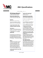
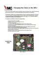
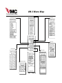
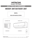
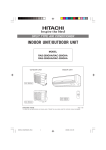
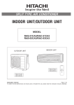
1
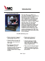
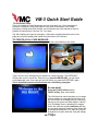
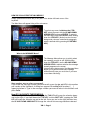
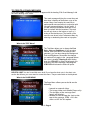
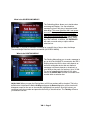
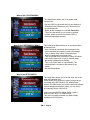
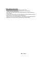
User’s Manual
The VM-3 Multimedia Video Message Generator
The Video Messenger Company
862 Judson Place • Stratford, Ct. 06615
Phone:(203)358-8842 Fax:(203)547-6216
email: :[email protected]
Website www.videomessenger.com
Table of Contents
Remote Video In
Introduction……………………………………………………………. Page 1
Quick Start Guide…………………………………………………….. Page 2
Menu Access………………………………………... Page 3
The Message Menu………………………………... Page 3
Menu Navigation…………………………………… Page 3
Creating a crawl message………………………... Page 4
The Text Menu……………………………………… Page 4
The Page Menu……………………………………... Page 4
The Scheduling Menu……………………………... Page 5
The Routing Menu………………………………….. Page 5
The Utilities Menu………………………………….. Page 6
The Preferences Menu…………………………….. Page 6
The Setup Menu…………………………………….. Page 6
What should you do now?…………………………Page 7
Function and Menu Commands At A Glance……………………. Page 8
Function and Menu Commands At A Glance Cont’d………….. Page 9
Function Keys………………………………………………………… Page 10
Short Cut Keys………………………………………………………... Page 11
Basic System Components………………………………………… Page 12
Components of the DV Pro Media Player Upgrade….………… Page 13
Basic Installation of the VM-3……………………………………… Page 14
Installing a Network of VM-3’s…………………………………….. Page 15
Installing the DV Pro Media Player Upgrade Package…… Pages 16-17
VM-3 Specifications…………………………………………………. Page 18
Changing the chips on the VM-3………………………………….. Page 19
VM-3 Menu Map………………………………………………………. Page 20
VMC’s Warranty………………………………………………………. Page 21
Sample Wiring Diagrams………………………………………..Pages 22-30
Basic insertion into a cable head end………….. Page 22
Multi-Channel installation with cable service… Page 23
Basic conference center installation…………… Page 24
Multi-Channel installation – stand alone………. Page 25
Complex court house installation………………. Page 26
Hotel Information channel………………………... Page 27
Multi dwelling unit with camera…………………. Page 28
Modem system installation………………………. Page 29
Cable System With Tuners At Each TV………… Page 30
Troubleshooting……………………………………………………… Page 31
Introduction
Remote Video In
The Video Messenger VM-3
The Video Messenger VM-3 is an
innovative, multimedia communications
device that is much more than a
character generator. It allows you, the
user, to effectively communicate with
your customers, guests, residents,
students, etc., using text, digital images
and video clips. You can educate,
inform and motivate your target
audience in ways that would have cost
thousands of dollars more before the
introduction of this little giant. This
installation manual allows you to take
maximum advantage of the VM-3. Start
with the Quick Start Guide, which starts
on the next page.
The VM-3 will allow you to:
Display hundreds of pages of
text messages on your TV’s.
Display text in dozens of
colors and brightnesses.
Schedule these messages by
time of day, day of week and
date range.
Link text messages to high
quality digital images and/or
video. This video is in MPEG (a
common digital format).
By using our network unit
(the VM-3NET), you can
distribute specific messages to
designated locations and
maintain control from a single
location.
Take control of what your target
audience is exposed to while in
your location with a high impact
presentation.
VM-3 • Page 1
VM-3 Quick Start Guide
They just installed the Video Messenger and your boss gave you a list of messages to
input and a schedule of their playing times. Don’t panic! Follow some of the simple
procedures outlined below then promise you will read the rest of this manual as soon as
possible to learn all there is to know. So – let’s start!
The VM-3 displays two types of messages: a full screen message (that takes most of the
page) and a crawl message (that crawls along the bottom of the screen).
TO CREATE A FULL PAGE MESSAGE:
Press the F1 KEY - a blank screen will appear with the cursor blinking in the center.
Blinking
Cursor
Blinking
Cursor
Blank screen using the VM-3 internal video
Blank screen using external video
Type in a line of your message like you would into a word processor. The ENTER KEY
will jump the cursor to a new line. Every time you press the ENTER KEY, you will create
a new paragraph, even if you only type one line before you press the ENTER KEY again.
This is important because colors and fonts are controlled by paragraph.
So now what?
Press the F9 KEY to Save and the
F8 KEY to Play. Now, more details...
The VM-3 has nine menus that allow you to assign
various qualities to a message like font style, size
and color; when the message will play; how long it
will stay on the screen and what image or video (if
a DV Pro Media Player is attached) is to appear
with it. We call these qualities attributes and they
are frequently mentioned in this manual. (Note that
pressing and holding the CTRL then the F key will
change the font styles, while the S key will change
the size.)
VM-3 • Page 2
HOW DO YOU ACCESS THE VM-3 MENUS?
Simply, press and hold down the (CTRL) KEY in the bottom left hand corner of the
keyboard.
The Main Menu will appear listing all the sub menus:
To get into any menu, hold down the CTRL
KEY, select the menu with the UP AND DOWN
ARROW KEYS and press ENTER. To return to
the Main Menu press the ESC KEY while holding
down the CTRL KEY. (Notice how the font and
background colors are controlled by paragraph,
which is defined with by pressing the RETURN
KEY).
What is the MESSAGE Menu?
The Message Menu allows you to quickly select
the message you wish to edit. While holding
down the CTRL KEY, use the UP AND DOWN
ARROW KEYS to make a selection-the message
instantly appears on the screen.
(Notice that the bottom part of the Message Menu
allows you to perform some basic message
utilities that will save you much time if you learn
to use them effectively).
Want another way to select a message?
If you know the message number you wish to edit, press the (go to) KEY in the number
pad section of the Keyboard. A dialog box appears Go to Msg with brackets [
]
appearing below it. Type in the message number you want to select in the brackets and
press Enter.
How DO I NAVIGATE THESE MENUS:
While holding down the CTRL KEY, tapping the TAB KEY will move the selection down
and to the right. If you hold down the CTRL KEY and the SHIFT KEY, tapping the TAB
KEY will move the selection up and to the left. Once you are in the right selection box,
the UP AND DOWN ARROW KEYS change the value of the message attribute selected.
VM-3 • Page 3
TO CREATE A CRAWL MESSAGE:
Press the F3 KEY - a blank blue screen will appear with the heading “Edit Crawl Message” with
the cursor blinking in the center
This crawl message will play the current time and
date when it displays at the bottom or top of the
screen. Many users employ the crawl line to
make special announcements in conjunction with
full-page message displays. It is also useful, if
you are showing a broadcast show and do not
want to interfere with the broadcast. The crawl
line will only show on the bottom or top 2 or 3
inches of the television set. The location of the
crawl line can be set in the Preferences Menu by
selecting or deselecting the crawl on top option.
What is the TEXT Menu?
The Text Menu allows you to change the Font
Style, Color and Brightness. If you are using
Internal Video (the VM-3’s own internal video
generator), you can also change the Background
Color and Brightness. Remember the changes
you make will only apply to the paragraph where
the cursor is located. Pressing A while holding
down the CTRL KEY to Select All will apply your
changes to the entire message. Releasing the
CTRL KEY will release the Select All option.
HELPFUL HINT! You don’t need this menu at all! If you learn the short cuts, in the short cuts
section that follows, you never need to access this menu. They are also listed on the Keyboard.
What is the PAGE MENU?
The Page Menu allows you to decide on the
following:
- Internal or external video.
- The image/video track (Media Player only).
- The duration of the message (how
long it will display).
- Whether or not to show the clock at the
top of the message. CTRL + H is the
short cut KEY for this option.
VM-3 • Page 4
What is the SCHEDULING MENU?
The Scheduling Menu allows you to decide when
a message will display. You can schedule a
message by time of day, day of week and within
date range. This menu gives the VM-3 real power
because it allows you to input your messages
days or months in advance and automatically run
them during the appropriate time. You navigate
the menu the same way you navigate the PAGE
and TEXT MENUS. In addition, the ENTER KEY
will mark or unmark a day or option within a
selection box.
Remember, if you want to schedule a message for a specific time of day or date; the Always
Time and Always Date lines must be unmarked! (NO CHECK MARK)
What is the ROUTING MENU?
The Routing Menu allows you to send a message to
any or all of the VM-3NET’s connected to the VM-3.
Routing allows the VM-3 to be a multi-channel, as
well as a multimedia device that can distribute
messages to different channels or locations in a
your facility at the push of a few keys. Up to 32 VM3’s can be networked in this fashion. Like other
menus, the ENTER KEY will mark or unmark a box
number within a selection box.
Helpful hint! When you open the Routing Menu, all 32 box numbers will be checked. This is the
default state. Hold down the Ctrl + Alt Keys and press the Return Key twice, all the checks will
disappear except for the one on the selected (highlighted) box number. Once this is done, you
can arrow to any box number and press the return key to check that box. The Tab Key will move
you between box sets.
VM-3 • Page 5
What is the UTILITIES MENU?
The Utilities Menu allows you to do system wide
functions like:
.
- Set the VM ID’s to give each box it’s own address #
- Download (Xmit) Preferences, the Clock and so on
to networked units.
- Delete all the messages in a unit with Reset ALL
- This menu also allows you to control an optional
modem, which can dial out to another VM-3 to
download messages remotely.
What is the PREFERENCES MENU?
The Preferences Menu allows you to set system wide
preferences like:
- Auto Xmit which downloads new messages to the
other networked boxes when you save a message.
- Turn on Smart Video, which is used when you
display messages over external video.
- Turn on Internal Video Override (Int Video OR) which
instructs the system not to look for external video,
preventing messages from flashing.
- Turn on or off the crawl on top command. The
system default is to crawl on the bottom of the
screen.
- Set the Startup Mode.
What is the SETUP MENU?
The Setup Menu allows you to set the clock, day of the
week and calendar date.
It also allows you to specify the type of remote device
connected to the RS 232 jacks, (i.e. Media Player,
modem, IP/LAN interface etc.) and the wait time between
crawl message presentations. Lastly, you can verify
and manually set the VM-3’s ID #.
When using the VMX Pro Media Player Comm A
shoud be set to DVD 175 command set.
This menu is usually accessed only when initially
installing the VM-3 system
VM-3 • Page 6
WHAT SHOULD YOU DO NOW?
- Review and learn the menu navigation and function keys.
- Review and learn the short cut keys at the bottom of the keyboard.
- Review the menu map (attached).
- Don’t panic, the VM-3 is really user friendly and worth your small investment in
time to learn it.
- If all else fails call your dealer or Video Messenger at (203) 358-8842. We will be
glad to help you move through its short learning curve.
- Finally, you can see a color presentation of this manual by downloading the VM-3
Manual from our website at www.videomessenger.com/downloads.
VM-3 • Page 7
Function and Menu Commands At A Glance
Some time saving Menu Functions:
While in the Message Menu the following keys are active...
Insert Key:
Creates an empty message slot before the current message.
Delete Key:
Deletes the selected message slot causing messages that follow to be
moved up in the list by one slot or message number.
Page Up:
Causes selected message to leap frog one place up on the message list.
Page Down:
Causes selected message to leap frog one place down on the message list.
Compact List
This menu command will re-sort the message list getting rid of
"holes" in the list.
Home Key:
Automatically brings you to the top of the message list
End Key:
Automatically brings you to message #250
Message Utility Functions:
Compact List
Clear Text
Clear Msg
Delete All
Delete Old
This allows an auto delete function for all messages that will never again
play because their date range has past.
XMIT Msg
This will do the following:
Transmit Clock Settings
Transmit Machine Preferences
Transmits only the current message to the networked units.
XMIT Msgs
Transmit Clock Settings
Transmit Machine Preferences
Delete messages in networked units
Transmit all messages to networked units
Req Msg
Allows you to upload the selected message number from a remote VM-3
Req Some
Allows you to upload a range of messages numbers from a remote VM-3
VM-3 • Page 8
Utility Menu:
OSD On/Off
Reset All (Set VM-3 to factory defaults)
Set VM ID's (Each VM-2 should have a unique ID Number)
The ID is displayed in the Setup Menu. The ID's may be set for all
networked units by using the Set VM ID's command in the utilities
menu.
This will Auto ID each networked unit in the order that they are connected.
Terminal functions allow you to operate the system with an optional modem.
Preference Menu:
Auto XMIT
(This item should have a check mark if you want a copy of the
message sent to networked units as you modify and save them).
Smart Video
(This item should have a check mark when only crawl line messages
are being use over external video. This preference selection ensures
the VM-3 always looks for an external video signal before putting up
it’s own internally generated screen).
XMIT Preference
(whenever a message is saved in the Master unit, it will be sent to the networked
units along with the clock settings and preferences).
XMIT Clock
(updates the networked units with the time and date in the master unit).
VM-3 • Page 9
FUNCTION KEYS:
KEY: -- FUNCTION:
Ctrl -- Press and release for edit mode to type and change text
Hold down to change message attributes (text color, brightness, font, scheduling etc.)
Esc -- With Ctrl Key held down, returns to the main menu
Arrow -- Used to change or pick a selection within a specific attribute box
Enter -- With Ctrl Key held down, will open a sub menu
Tab -- Used to navigate to different menu boxes
F1 -- brings up the next available new, blank full page message screen
F2 -- allows editing of a full page message
F3 -- brings up the next available new, blank crawl message screen
F4 -- allows editing of a crawl message
F5 -- Moves to the previous message while in the edit mode
F6 -- Moves to the next message while in the edit mode
F7 -- Puts programming in a pause mode indefinitely
F8 -- Activates the play mode
F9 -- Saves the edit changes made to a specific message
F10 -- Previews a message with attributes such as duration and image link
F11 -- Copies all the text and attributes of a message into a clipboard to paste over another
message
F12 -- Pastes the text and all attributes of a message into a blank message
VM-3 • Page 10
**VM-3 KEYBOARD SHORT CUT KEYS:**
KEY: -- FUNCTION:
Ctrl C -- Center align text
Ctrl L -- Left align text
Ctrl R -- Right align text
Ctrl F -- Font style (five rotating selections)
Ctrl S -- Font size (four rotating selections)
Ctrl P -- Preset color combination (16 preset font and background combo’s)
Ctrl T -- Select color of text (16 colors)
Ctrl B -- Select brightness of text (8 selections per color)
Ctrl Alt T -- Select color background (16 colors)
Ctrl Alt B -- Select brightness of background (8 selections per color)
Ctrl A -- Select all text (paragraphs) of a message
Ctrl V -- Switch between internal and external video
Ctrl H -- Switch time/date header option on and off
Delete or Backspace -- will delete one character at a time.
Shift Delete -- will delete text in a paragraph.
Alt Delete -- will delete text in a message, leaving the attributes alone (font size, color etc.)
Shift Alt Delete Save -- will delete entire message.
Home -- move the cursor to the top of the first message page.
End -- moves the cursor to the end of the last message page.
"^t" -- sets time for crawl message.
"^d" -- sets date for crawl message only.
VM-3 • Page 11
Components of the VM-3
Basic System
Remote Video In
When you unpack the VM-3, the basic system will include the following:
1 Video Messenger
VM-3
1 Standard 101 AT Keyboard
(Black or Baige)
1 Standard IEC 320
Power Cable
2 6ft. BNC to RCA
Video Cables
1 Owner’s Manual
1 Warranty Card
Questions? Call us at
(203) 358-8842
VM-3 • Page 12
Components of the DV Pro
Media Player Upgrade
Package
Remote Video In
The Media Player Upgrade Package (DV#1) includes:
The DV Pro Media Player with 512 MB Compact Flash Card. The
unit can play back on command Mpeg 1, 2 & 4 video, Mpg3 audio
and jpeg & bmp stills.
256 MB USB Flash Drive for updating the DV Pro Media Player
DV Studio Plus Authoring Software. This software allows
the user to add images and video to the Compact Flash
Card for use in the DV Pro Media Player. With this
software, the player can be set up to act as a server for the
VM-3 or automatically present a play list by itself.
*Customized video editing services are available from VMC directly.
VM-3 • Page 13
Basic Installation of the VM-3
Remote Video In
The instruction step numbers correspond
to the numbers in the diagram to the right.
VM-3 Rear Panel
1. Unpack the VM-3 and place it where you
can have easy access to the rear panel.
2. Using one of the Standard (BNC TO
RCA) Cables, connect the BNC end to the
jack marked "Video Out Edit." Plug the
RCA end into an edit monitor.
3. Using the other Standard (BNC TO RCA)
Cable, connect the BNC end to the jack
marked "Video." Plug the RCA end into
the television system. In most cases this
cable is plugged into a modulator (using
an RCA to F adaptor) or a display monitor.
If the modulator is farther than 6 feet away,
a custom cable will have to be made by
your installer.
Video In
4. If external video is going to be used,
connect another Standard (BNC TO RCA)
Cable to the jack marked "Video In." The
other end of this cable can be connected
to a VCR, Satellite Receiver, Camera, DVD
player or any device that has a video
output jack.
Video In
5. Turn the VM-3 so you can access the
front panel. Plug the keyboard in the Din
jack marked "Keyboard."
VM-3 Front Panel
6. Connect the power cord from the
VM-3 to an electrical outlet or
Figure
1
recommended
surge protector.
7. Call (203) 358-8842 if you are having
a problem completing these steps.
Character Generator/Video Controller
P
5
Jack to connect the Keyboard
VM-3 • Page 14
Remote Video In
V
Installing a Network of VM-3’s
These instructions assume you have completed the basic installation.
VM-3
The VM-3 unit is very easy to network
with other VM-3’s. Connecting VM3NET’s to a VM-3 Control Unit allows the
operator to send different messages and
image/video links to more than one
location or video source. This can be
done from one location while
maintaining control of the entire
network.
To Edit Monitor No Edit
Screen Presentation In Out
1. After performing the basic installation
on a VM-3NET, simply connect the din
cable pictured to the right from one VM-3
to the next. This connection is made
through the "Network" ports. The
"Network Out" Port is connected to the
next VM-3NET’s "Network In" Port. This
is repeated until all the VM-3NET’s are
connected.
From Network Out
To Network In
VM-3NET
2. After all the units are powered up, the
VM-3 Control Unit knows how many VM3NET’s are connected. Setting the
VMID’s is done from the Utilities Menu.
This gives each box a unique address.
3. VMX Pro Media Players can be installed
on any or all of the VM-3NET network units.
4. Controlling the VM-3NET’s is done
through the Routing Menu while editing
with the VM-3 Control Unit.
5. Call (203) 358-8842 if you are having a
problem completing these steps.
Remote Video In
Video Out Video Out
VM-3 • Page 15
From Network Out
To Network In
VM-3NET
Installing the DV Pro Media
Player Video Package
The instruction step numbers correspond to the numbers in the illustrations to the right.
1. Unpack the DV Pro Media Player and place it
on top of the VM-3 where you can have easy
. access to the rear panels (as shown). Turn on
the VM-3 by plugging in the black power cable.
2. Find the Interface (Black) Cable. Insert the 9pin end into the Comm A Port on the VM-3 and
the Mini Plug end into the RS 232 jack on the DV
Pro Media Player.
1.
2.
2.
3. For audio, insert one end of the RCA cable
(provided) into the audio out (Red jack for
mono) on the Player as shown. For stereo use
two RCA cables. Insert the other end(s) of this
cable into the audio-in(s) of a TV, amplifier or an
RF modulator.
4. Attach the BNC end of one of the black Video
Cables to the Video (in) plug on the VM-3. The
other end of this cable is a standard RCA plug.
Insert this end into the back of the Player. Look
for a yellow jack marked "Composite”.
5. Attach the BNC end of the other black Video
Cable to the Video (out) plug on the VM-3
(marked Edit). The other end of this cable is a
standard RCA plug and can be inserted into an
edit monitor or other video display. Using this
plug allows the user to edit off line.
VMC • Page 16
3.
4.
4.
5.
Installing the VM-3 Video
Upgrade Package
Continued…
6. The last Video Out (unmarked) is for
insertion into a modulator or video display
to be seen by intended viewers. This Is
usually a custom made cable provided by
your installer.
6.
7. Connect the power cord on the DV Pro
Media Player to an electrical outlet or
recommended surge protector. Turn on the
VM-3 by connecting the power cord.
7.
8. At this point, you can insert the Compact
Flash Card (provided) that contains your
images and video.
9. Turn on the DV Pro Media Player by
pressing the power switch. The player will
take about 10 seconds to boot up and will
show the first track on the play list.
8.
10. Now you are ready to get started. Using
the VM-3’s keyboard, go to the Page menu
and tab down to Track. With the right hand box
highlighted, you can arrow up and down
from files 1 to 99. To select an image in a
track higher than 99, use the left box to put
the first one or two digits of the track
number and the right hand box to put in the
last two digits of the track number. One
second after going to a file number, the
Player will display the image or video in that
track
9.
Call (203) 358-8842 if you are having a
problem completing these steps.
VM-3 • Page 17
VM-3 Specifications
Remote Video In
VM-3 • Page18
Changing the Chips on the VM-3
Remote Video In
V
There are two flash memory chips in the VM-3. One, the Program Chip, controls the features
and functions of the unit. The other flash, Memory Chip stores your messages.
Occassionally, VMC issues a program update to improve features and make the unit easier
to use. As a result, you may be asked from time to time by the Video Messenger Company
to relay what version of the Program is installed in your VM-3. You can find the software
version # at the bottom of the Setup Menu.
To Edit Monitor No Edit
Screen Presentation In Out
To replace the battery, follow the steps below:
1. Unplug the power to the VM-3.
2. Remove two screws on the top of the unit.
3. Pull the top panel off.
4. Locate the VM-3 PROGRAM CHIP as shown in the image below.
5. Carefully pry the VM-3 PROGRAM CHIP out of the socket with the flat edge
of a small screwdriver.
6. Insert the new VM-3 PROGRAM CHIP into the socket making sure that the
notch is is facing right and all pins line up correctly.
7. Press firmly to seat the FLASH PROGRAM CHIP. Make sure there are no bent pins.
8. Re-assemble the top panel.
9. Replace the two screws, being careful not to over-tighten them.
10. Plug the VM-3 into an outlet.
Inside the
VM-3
VM-3 • Page 19
VM-3 Menu Map
Remote Video In
Message Menu
Scheduling Menu
Text Menu
Main Menu
Page Menu
Routing Menu
Utility Menu
Setup Menu
Preferences Menu
VM-3 • Page 20
VMC’S Warranty
Remote Video In
The Video Messenger Company warrants your Video Messenger to be free from
defective materials and workmanship for a period of 1 year. VMC covers both parts
and labor.
SHOULD YOUR VIDEO MESSENGER NEED SERVICING DURING THE
FIRST YEAR, THE VIDEO MESSENGER COMPANY WILL REPAIR OR
REPLACE THE DEFECTIVE UNIT AT ITS DISCRETION WITHIN 72 HOURS
OF RECEIPT (not including weekends, holidays, or shipping time).
The following will void the above warranty:
- Abuse
- Accident
- Alteration
- Damage in transit (other than original shipment from factory)
- Failure to return warranty card within 10 days of purchase
- Failure to follow return procedures
- Maintenance procedures not followed
- Modification
- Misuse, including connection with wrong current or voltage
- Negligence
To return a VMC product:
1. Call us at (203) 358-8842. We may help you correct the problem by phone. If
your unit must be returned, you must obtain authorization before shipment.
2. Ship unit in original factory carton only unless instructed otherwise.
3. Ship via UPS or equivalent and insure for full value.
4. All shipments must be prepaid. No CODs accepted.
In closing:
We wish you good luck with your new VM-3, and hope you can reap much benefit
from this innovative product. Feel free to write us, sharing with us some of the
creative ways in which you’ve tapped into this new method of communicating. If you
find your video needs are expanding beyond your present system, please contact us
for more information on our full line of Video Messenger products.
VM-3 • Page 21
Basic Wiring Diagram For Insertion Into Cable
Head End For a Bar, Lounge or Restaurant
Allow for editing messages off line
RF Modulator
Channel (?)
VM-3
Keyboard
Cable Ready
VCR/Tuner
Drop
To TV’s
Combiner
Main
Cable
This system allows an owner to insert characters over any cable
channel. Channel (#) depends on where there is room in the
spectrum to insert a channel.
VM-3 • Page 22
Amp
Splitter
Drop Tap
Main Cable
Video Out
Cable Tuner
VCR/Tuner
Cable Tuner
VCR/Tuner
RF Modulator
RF Modulator
RF Modulator
RF Modulator
Keyboard
Allows user to edit
messages offline
Wiring Diagram For Insertion Into Multi-Source
Cable Television System a Bar, Lounge or Restaurant
VM-3’s
From source of video to Video Messenger
to Modulator to TV’s
Combiner
To TV’s
This system allows messages to appear on multiple sources of video or programming. In
the example above, four video messengers act as one on four separate channels
displayed in the bar/restaurant area.
Wiring Diagram For Conference Centers or Facitlites with Different
Messages in Various Areas of A Facility - Six Source RF System
RF Channels Out
RF Modulator 2
RF Out
RF Modulator 4
Combiner
RF Modulator 6
RF Modulator 8
Edit
Video
Out
RF Modulator 10
13” Edit
Monitor
RF Modulator 12
Video out To
Keyboard
VM-3
Drop Taps to
Each TV
VM-3Net
VM-3Net
27”
Monitor
27”
Monitor
27”
Monitor
27”
Monitor
27”
Monitor
27”
Monitor
Out
to
TV’s
VM-3Net
VM-3Net
VM-3Net
VM-3Net
This system allows any TV to display any source
by changing the channel.
VM-3 • Page 24
Wiring Diagram For Insertion Into Multi-Source
Television System
Keyboard
Sat. Receiver
RF Modulator
Sat. Receiver
Sat. Receiver
Sat. Receiver
RF Modulator
RF Modulator
RF Modulator
From source of video to Video Messenger
to Modulator to TV’s
To TV’s
Combiner
This system allows messages to appear on multiple sources of
video or programming. In the example above, four video
messengers VM-3’s act as one on four separate channels
displayed in the bar/restaurant area.
VM-3 • Page 25
Video Out
Video In
Keyboard
Office
RF Modulator
RF Modulator
RF Modulator
RF Modulator
RF Modulator
RF Modulator
RF Modulator
RF Modulator
RF Modulator
RF Modulator
RF Modulator
RF Modulator
RF Modulator
C
O
M
B
I
N
E
R
Wiring Diagram For Insertion Into Multi-Source Television
S t
communications Out to
System Capabilities:
• Each court room has display
of its own schedule
• Each court room has a
camera
• TV’s in each judge’s
chamber can tune to any
schedule or camera.
• All schedules are centrally
controlled in the office.
RF Modulator
= Drop Taps
VM-3 • Page 26
Basic Wiring Diagram For Insertion Into Cable Head End or
Private Cable System like a Hotel
RF Modulator
Edit
Video
Out
13” Edit
Monitor/
TV
Video out To
Keyboard
DV Pro
Media
Player
Splitter/
Combiner
Out to
TV’s
In
Rooms
Coaxial cable should be RG-6 Shielded.
VM-3 • Page 27
Cable
from
Hotel
headend
Basic Wiring Diagram For Insertion Into Cable Head
End or Private Cable System like a Multi-dwelling Unit
RF Modulator
Channel # tbd
Edit
Video
Out
13” Edit
Monitor/
TV
Video out To
VM-3
Keyboard
Splitter/
Combiner
Camera
Out to TV’s
In Rooms
Coaxial cable should be RG-6 Shielded.
VM-3 • Page 28
Cable
from
Hotel
headend
Basic Wiring Diagram Video Messenger Modem System
Location #2
Modem
VM-3
Edit
Video
Out
Out to
TV
13” Edit
Monitor/
TV
POTS LINE
Modem
Keyboard
VM-3
Location #1 Headquarters
Out to
TV
Location #3
Modem
VM-3
Pots line = Plain old telephone service
VM-3 • Page 29
Out to
TV
Wiring Diagram For Insertion Into
Cable System With Tuners At Each TV
Departments with
VMConsole and
Internet Access
Cable Tuner
Cable Tuner
Network In/Out
Drop Tap
Network In/Out
Drop Tap
General Management
Human Resources
Cable Tuner
Cable Tuner
Network In/Out
Engineering
Telecomunications
RF
AMP
Drop Tap &
Terminator
Drop Tap
This diagram illustrates how multiply
users can input messages into a wireless
VM-3 Network. VMC recommends that
the network cable be either CAT-5 or
shielded twisted pairs. The RF coaxial
cable should be RG-6 shielded or better.
VMC suggests that each user be assigned
a range of message numbers for their
exclusive use.
VM-3 • Page 30
Pin out for
Network Cable
Troubleshooting
Remote Video In
What follows are the most common issues that users call about when they need help with the Video
Messenger, VM-3.
1) I get only a blank screen when I try to enter or edit a message.
More often than not, the user is not looking at the video source coming out of the “Video Out - Edit”
jack. There are two video outs on the VM-3; one is for editing and one is for display. The display out,
the plain “Video Out” jack is suppose to go blank during an editing session so that the viewers
(residents, quests, customers, etc.) cannot see what you are doing during the editing session.
The solution to this problem is to make sure that the video you are looking at is coming from the
“ Video Out – Edit” jack. This usually means making sure that your TV/Monitor is set to Video as
opposed to being set to a TV channel.
2) None of my messages play even though they are saved.
This problem is usually caused by bad clock and calendar settings. If your unit is not on a surge
protector and it is subjected to an electrical surge due to lightning or some other cause, the clock can
reset to it’s default start date. This setting is 1/1/99, Monday, 12:00 am. If you are using the
scheduling menu to schedule your messages, they will be outside the play window because of the bad
clock or calendar setting.
The solution is to reset your clock (in the SETUP MENU) and periodically check it to make sure it is
correct. A surge protector usually solves this problem permanently.
3) The VMX Pro Media Player is not putting out any Video – all I get is a blue background on
the VM-3.
This problem is caused by variety of electrical disturbances or a disconnected video cable.
After checking the video cable, the solution is to turn off the Media Player by holding in the power
switch for 5 seconds. With the VM-3 powered up and connected to the video out of the Media Player,
power up the Media Player and without the USB Flash Drive attached. Once the Media Player boots
up, reinsert the USB Flash Drive. The unit will operate normally after this procedure is completed.
4) The VMX Pro Media Player is not responding to the VM-3. The images are not changing.
This problem is cause by one of two things: 1) The serial cable is disconnected from the Media
Player or the COMM A port is not set correctly,
The solution to the first issue is to reconnect the serial cable. The solution to the second issue is to
open up the SET UP MENU, tab down to the COMM A port and using your up/down arrow keys set
the port to DVD 175 command Set. The Media Player will then respond to the VM-3.
VM-3 • Page 31