1
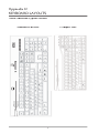
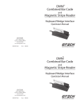
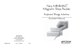
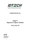
VersaKey
TM
Standard & Compact Series
POS Keyboard
Quickstart Manual
FCC WARNING STATEMENT
This equipment has been tested and found to comply with the limits for a
Class B digital device, pursuant to Part 15 of FCC Rules. These limits are
designed to provide reasonable protection against harmful interference when
the equipment is operated in a commercial environment. This equipment generates, uses, and can radiate radio frequency energy and, if not installed and
used in accordance with the instruction manual, may cause harmful interference to radio communications.
FCC COMPLIANCE STATEMENT
This device complies with Part 15 of the FCC Rules. Operation of this device
is subject to the following conditions: this device may not cause harmful
interference and this device must accept any interference received, including
interference that may cause undesired operation.
CANADIAN DOC STATEMENT
This digital apparatus does not exceed the Class B limits for radio noise for
digital apparatus set out in the Radio Interference Regulations of the Canadian Department of Communications.
Le présent appareil numérique n’émet pas de bruits radioélectriques dépassant
les limites applicables aux appareils numériques de las classe B prescrites
dans le Réglement sur le brouillage radioélectrique édicté par les ministère
des Communications du Canada.
CE STANDARDS
Testing for compliance to CE requirements was performed by an independent
laboratory. The unit under test was found compliant to B.
LIMITED WARRANTY
ID TECH warrants to the original purchaser for a period of 36 months from the date
of invoice that this product is in good working order and free from defects in material and workmanship under normal use and service. ID TECH’s obligation under
this warranty is limited to, at its option, replacing, repairing, or giving credit for
any product which has, within the warranty period, been returned to the factory of
origin, transportation charges and insurance prepaid, and which is, after examination,
disclosed to ID TECH’s satisfaction to be thus defective. The expense of removal and
reinstallation of any item or items of equipment is not included in this warranty. No
person, firm, or corporation is authorized to assume for ID TECH any other liabilities
in connection with the sales of any product. In no event shall ID TECH be liable
for any special, incidental or consequential damages to purchaser or any third party
caused by any defective item of equipment, whether that defect is warranted against or
not. Purchaser’s sole and exclusive remedy for defective equipment, which does not
conform to the requirements of sales, is to have such equipment replaced or repaired
by ID TECH. For limited warranty service during the warranty period, please contact
ID TECH to obtain a Return Material Authorization (RMA) number & instructions for
returning the product.
THIS WARRANTY IS IN LIEU OF ALL OTHER WARRANTIES OF MERCHANTABILITY OR FITNESS FOR PARTICULAR PURPOSE. THERE ARE NO OTHER
WARRANTIES OR GUARANTEES, EXPRESS OR IMPLIED, OTHER THAN
THOSE HEREIN STATED. THIS PRODUCT IS SOLD AS IS. IN NO EVENT
SHALL ID TECH BE LIABLE FOR CLAIMS BASED UPON BREACH OF EXPRESS OR IMPLIED WARRANTY OF NEGLIGENCE OF ANY OTHER DAMAGES WHETHER DIRECT, IMMEDIATE, FORESEEABLE, CONSEQUENTIAL
OR SPECIAL OR FOR ANY EXPENSE INCURRED BY REASON OF THE USE
OR MISUSE, SALE OR FABRICATIONS OF PRODUCTS WHICH DO NOT CONFORM TO THE TERMS AND CONDITIONS OF THE CONTRACT.
The information contained herein is provided to the user as a convenience. While
every effort has been made to ensure accuracy, ID TECH is not responsible for damages that might occur because of errors or omissions, including any loss of profit or
other commercial damage, nor for any infringements or patents or other rights of third
parties that may result from its use. The specifications described herein were current
at the time of publication, but are subject to change at any time without prior notice.
©2006 International Technologies & Systems Corporation. The information contained
herein is provided to the user as a convenience. While every effort has been made to
ensure accuracy, ID TECH is not responsible for damages that might occur because
of errors or omissions, including any loss of profit or other commercial damage. The
specifications described herein were current at the time of publication, but are subject
to change at any time without prior notice.
ID TECH is a registered trademark of International Technologies & Systems Corporation. VersaKey and Value through Innovation are trademarks of International
Technologies & Systems Corporation.
Table of Contents
Section 1. Introduction
1
Section 2. Installation & Operation
2
Section 3. Reader Configuration
3
Section 4. Specification Keyboard
4
Section 5. Specification Reader
5
Section 6. Trouble Shooting
6
Appendix A. Magnetic Stripe Default Settings
7
Appendix B. Connector Pin Assignments
7
Appendix C. Magnetic Stripe Data Output Format
8
Appendix D. Keyboard Layout
9
Section 1
INTRODUCTION
ID TECH VersaKey POS Keyboards provide data entry primary for POS and
security applications. Two sires are available, compact and full size. The
VersaKey Compact is in compact 14” x 7” form factor, full-function keyboard
with 103 key layout. The full-size keyboard is a standard 18.5” x 8” form
factor. The VersaKey has Typematic keyboard operation with a good tactual feel. Included is a reader for MagStripe cards. There are four LEDs to
indicate keyboard function status. Many country specific keyboard layouts
are available.
VersaKey product with a PS/2 communication cable always sends keyboard
and MagStripe data in scan code format. VersaKey product with a USB communication cable always sends keyboard data in scan codes format. Moreover, many VersaKey USB models send MagStripe data in scan code format
(as though the data came from keystrokes); however, there is a second option
where some VersaKey models communicate MagStripe data in ASCII characters through the USB cable.
In this second option, MagStripe data is sent as USB-HID or USB-CDC
device class interface (not in USB-keyboard scan code format). The purpose
of this second option is separation of MagStripe data from keyboard data.
This allows the VersaKey to serve separate & different keyboard and MagStripe applications in the same PC. The VersaKey Model number defines the
communication variations. See ID TECH User Manual 80074503-001 for
additional information using separate USB interfaces.
The VersaKey magnetic card reader has full data editing capabilities. The
reader is fully programmable using a Configuration Utility Software available
at the ID TECH website (http://www.idtechproducts.com). The data can be
formatted with preamble & postamble (a.k.a. prefix and suffix). Terminator
characters can be added to match the format expected by the host application.
In addition, complex data editing routines can be stored in the reader that
further arranges the data before it is output to the host.
The VersaKey provides a USB (keyboard) or PS/2 communication output.
This output is conveniently shared between the keyboard and the MagStripe
reader. The VersaKey Standard full sized comes two-port USB hub that can
be used for scanners or PIN pads. VersaKey Keyboard is compatible with
Windows 98, 2000, XP, & Vista operating systems
Both the keyboard and the reader are industry proven. The keyboard provides more than 20,000,000 key operations; the reader has an operational
life greater than 1,000,000 swipes. The VersaKey meets FCC Class B & CE
regulatory requirements. ESD immunity is greater than 15KV with no damage to the circuits.
1
Section 2
INSTALLATION & OPERATION
The VersaKey keyboard always has a single communication cable equipped
with either a USB or a PS/2 cable connection. Both the keyboard scan codes
and reader data are always transmitted through this single communication
cable. Computers typically have only one PS/2 (standard keyboard connection); this connection must be used for the PS/2 configured VersaKey. The
computer may have several USB connection ports; any of these ports can be
used to connect the USB keyboard.
To install the VersaKey, close any open applications and Shut Down the computer. Determine the VersaKey connection type and locate the appropriate
connection receptacle on the computer. Securely install the cable connector
into the computer receptacle. Re-start the computer.
When the VersaKey is powered, it performs a self test and initiation sequence
with the computer. During the self test the MagStripe reader will beep. The
keyboard power LED will light to indicate power is applied. The LEDs will
show the status of the Scroll Lock, Num Lock, & Caps Lock functions. Test
the keyboard with normal use in a text editor like Word.
Also, test the reader. For readers with a PS/2 or USB-Keyboard type communication interface, MagStripe data is transmitted such that the card data
appears to be coming directly from the keyboard. This makes the reader a
pseudo-keyboard data source and transparent to the keyboard PC application
software.
For VersaKey keyboards with a USB interface, the reader may not use a
USB-keyboard type interface. In this case, MagStripe data is sent to the PC’s
MagStripe application in an ASCII character format instead of in keyboard
scan code format. (See the Introduction Section for more information on the
reader communications types.)
Test the reader by swiping a magnetic stripe card through the reader slot. The
magnetic stripe must be facing toward the front of the keyboard. A beep will
also sound to indicate a good read on each magnetic track, as appropriate. If
three tracks are available on the reader and all have been read successfully,
the reader will beep three times. Readers with a non-keyboard type of communication interface must be tested using the PC’s MagStripe application
software; otherwise, for readers with a keyboard (scan code) output, the card
data is seen on the text editor as when testing the keyboard.
2
Section 3
READER CONFIGURATION
The magnetically encoded data on the MagStripe is decoded (read) by card
reader. The stripe data has a fixed format defined by the ISO standards. The
ISO fixed format is not always convenient or useful for card reading applications. The solution is for the card reader to decode the stripe data and then
arrange the data into useful format and content.
The VersaKey Reader is an intelligent magnetic stripe reader that decodes,
verifies, and transmits stripe data. The reader also provides a convenient
formatting and content editing capability for transmitted data. The MagStripe
data can be edited and arranged by the reader; characters can be added to
the formatted data. The added characters form either a prefix or a suffix to
the formatted MagStripe data. To support the reader’s formatting capability,
ID TECH provides an easy to use configuration utility, Magswipe Software.
Configuration settings can also enable the reader to work with the host system
communication port settings; data transmission intervals or data rates for
example.
Magswipe Software supports the Windows 98, Windows ME, Windows 2000,
Windows XP, and Windows Vista operating systems.
When readers are configured appropriately to an application and computer,
these configuration settings are stored in the reader’s non-volatile memory
(they are not affected by the cycling of power).
DEFAULT SETTINGS
The reader is shipped from the factory with the default settings already
programmed. See Appendix A. The reader has been factory programmed
with the least restricted settings, thus making the reader ready to read most
standard format magnetic stripe cards.
3
Section 4
SPECIFICATION KEYBOARD
MECHANCIAL
Keyswitch
Total Travel
Operating Force
Keyboard Housing
Color
Size
Material
4.0 ± 0.5 mm
50 ± 7g
Black
Full Size:
469.9 mm (L) x 203.9 mm (W) x 42.8 mm (H)
18.5 inch (L) x 8.03 inch (W) x 1.69 inch (H)
Compact:
358.8mm (L) x 177.8mm (W) x 40.0mm (H)
14.1 inch (L) x 7.0 inch (W) x 1.6 inch (H)
ABS
Cable Information
Jacket Material
Length
PC Connector
PVC jacket with Aluminum Shielding
1.5 M (5ft.) Overall
PS/2 or USB
Drop
610 mm (24”) Drop: 1 corner, 2-sidelines, 3-sides
Vibration
60 Hz/sec 3 mm amplitude X,Y,Z each axis at 2 hours
Operating Temperature
0°C to 40°C (32°F to 104°F)
Storage Temperature
-20°C to 40°C (- 4°F to 104°F)
ELECTRICAL
Power Requirement
+5.0 VDC ±10%, 60ma Max
Industry Requirements
FCC class B and CE
RELIABILITY
Operating Life
20,000,000 keystrokes
ESD Immunity
MTBF
0KV to 8 kV min, without data loss.
8KV to 15 kV min, will function after reset
More than 60,000 power on hours
4
Section 5
SPECIFICATION READER
Number of tracks
Compatibility
Communications
Output data formatting
Operating Life
Card speed range
Audio beeper
Track 1 & 2 or Track 1, 2 & 3
ISO 7810 and 7811-1 through -6 cards.
Reads AAMVA driver license cards.
Decoded track data sent through Keyboard
communications cable.
Default card data output format or customized
data output format is programmable through PC
configuration utility. See Appendix A for default
settings.
1,000,000 card swipes
3 to 60 IPS (Inches Per Second)
Indicates error free card data reading
5
Section 6
TROUBLE SHOOTING
The data from the reader is not as expected.
The reader is shipped from the factory with the default settings already
programmed. See Appendix A for the Default Settings. The default settings
can be customer modified by using the MagSwipe Configuration Utility. See
Section 3.
The reader does not output data.
The reader will beep when power is applied to the VersaKey. The reader
will also beep for each track correctly read from a magnetic stripe. Use a
known good credit card to test the reader operation. Insure that a text input
application (such as Windows Notepad) is open and selected during the test.
The keyboard does not function with the computer.
If the power indicator LED is off, the keyboard may not be fully connected to
the computer. Check the connections. Check that the computer power is on.
If the power indicator LED is on and the VersaKey is a USB type, the driver
may not be loaded properly on the computer. Check the Device Manager
in Hardware Properties of the computer. The driver is a standard windows
driver for operating systems Windows 98SE and later.
6
Appendix A
MAGNETIC STRIPE DEFAULT SETTINGS
Function
Beep Volume
Inter-Character Delay
Track Selection
Data Output Format
Track Separator
MSR Reading
Decoding Method
Terminator ID
Polling Interval
Default Value
High
2 ms
Any Track
ID TECH Format (See Appendix C)
See Appendix C
Enable
Decoding in Both Directions
ENTER
1 ms (USB)
Appendix B
CONNECTOR PIN ASSIGNMENTS
PS/2 Connector, 6 pin DIN
Connector Pin
2
4
6
1
3
5
Signal
Not Used
+5 V
Not Used
Data
Ground
Viewed from cable end
Clock
USB, 4 pin USB plug
Connector Pin
1
2
3
4
Signal
+5 V
- Data
+ Data
Ground
7
Appendix C
MAGNETIC STRIPE DATA OUTPUT FORMAT
The Reader is shipped from the factory with the following magnetic stripe
default settings already programmed:
Magnetic Track Basic Data Output Format
Track 1: <SS1><T1 Data><ES><TS>
Track 2: <SS2><T2 Data><ES><TS>
Track 3: <SS3><T3 Data><ES><Terminator>
where: SS1(start sentinel track 1) = %
SS2(start sentinel track 2) = ;
SS3(start sentinel track 3) = ; for ISO,
% for AAMVA
ES(end sentinel all tracks) = ?
<TS> = <ENTER> key
Terminator = <ENTER> key
Start or End Sentinel: Characters in encoding format which come before the
first data character (start) and after the last data character (end), indicating the
beginning and end, respectively, of data.
Track Separator: A designated character that separates data tracks.
Terminator: A designated character that comes at the end of the last track of
data in order to separate card reads.
LRC: Check character, following end sentinel. (The reader will verify it when
decoding, but this will not be sent as part of the data.)
8
Appendix D
KEYBOARD LAYOUTS
North American Typical Format
Standard Full Size
Compact Size
9
ID TECH
10721 Walker Street
Cypress, California 90630
(714) 761-6368
www.idtechproducts.com
80074502-001 Rev D
R10/07