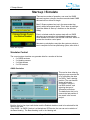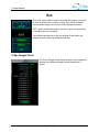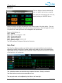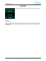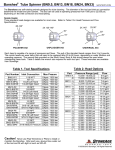
1
C-Scape Manual C-Scape Manual Version 1.10 Revision Date: November 26, 2012 C & C Technologies, Inc. C-Nav DGNSS 730 E. Kaliste Saloom Road Lafayette, LA 70508 U.S.A. www.cnav.com C-Scape Manual Release Notice This is the November 2012 release of the C-Scape Manual. Revision History Date Version Changes Comments 11/26/2012 1.10 CCTHOMPS Updated to meet C-Scape v1.1.11 9/24/2012 1.9 CCTHOMPS Updated to meet C-Scape v1.1.10 9/17/2012 1.8 CCTHOMPS Updated to meet C-Scape v1.1.9 8/31/2012 1.7 CCTHOMPS Updated to meet C-Scape v1.1.8 8/3/2012 1.6 CCTHOMPS Updated to meet C-Scape v1.1.7 5/24/2012 1.5 CCTHOMPS Updated to meet C-Scape v1.1.3 11/30/2011 1.4 CCTHOMPS Updated to meet C-Scape v1.1.0 11/3/2011 1.3 CCTHOMPS Updated to meet C-Scape v1.0.7 09/23/2011 1.2 CCTHOMPS Updates to meet C-Scape v1.0.6 04/28/2011 1.1 CJC Updates to meet C-Scape v1.0.4 03/01/2011 1.0 CJC Initial Release Version 1.10 Page 2 of 86 11/26/2012 C-Scape Manual Trademarks The C-Nav logo is a trademark of C & C Technologies, Inc. C-Nav is a trademark of C & C Technologies, Inc. Microsoft, MS-DOS, Windows, Windows 95, Windows 98, Windows 2000, Windows NT, Windows XP, and Windows 7 are trademarks of Microsoft Corporation. All other brand names are trademarks of their respective holders. Disclaimer of Warranty EXCEPT AS INDICATED IN “LIMITED WARRANTY” HEREIN, C & C TECHNOLOGIES, SOFTWARE, FIRMWARE AND DOCUMENTATION ARE PROVIDED “AS IS” AND WITHOUT EXPRESSED OR LIMITED WARRANTY OF ANY KIND BY EITHER C & C TECHNOLOGIES, INC., OR ANYONE WHO HAS BEEN INVOLVED IN ITS CREATION, PRODUCTION, OR DISTRIBUTION INCLUDING BUT NOT LIMITED TO THE IMPLIED WARRANTIES OF MERCHANTABILITY AND FITNESS FOR A PARTICULAR PURPOSE. THE ENTIRE RISK, AS TO THE QUALITY AND PERFORMANCE OF THE C & C TECHNOLOGIES HARDWARE, SOFTWARE, FIRMWARE AND DOCUMENTATION, IS WITH YOU. SOME STATES DO NOT ALLOW THE EXCLUSION OF IMPLIED WARRANTIES, SO THE ABOVE EXCLUSION MAY NOT APPLY TO YOU. Limitation of Liability IN NO EVENT WILL C & C TECHNOLOGIES, INC., OR ANY PERSON INVOLVED IN THE CREATION, PRODUCTION, OR DISTRIBUTION OF THE C & C TECHNOLOGIES SOFTWARE, HARDWARE, FIRMWARE AND DOCUMENTATION BE LIABLE TO YOU ON ACCOUNT OF ANY CLAIM FOR ANY DAMAGES, INCLUDING ANY LOST PROFITS, LOST SAVINGS, OR OTHER SPECIAL, INCIDENTAL, CONSEQUENTIAL, OR EXEMPLARY DAMAGES, INCLUDING BUT NOT LIMITED TO ANY DAMAGES ASSESSED AGAINST OR PAID BY YOU TO ANY THIRD PARTY, RISING OUT OF THE USE, LIABILITY TO USE, QUALITY OR PERFORMANCE OF SUCH C & C TECHNOLOGIES’ SOFTWARE, HARDWARE, AND DOCUMENTATION, EVEN IF C & C TECHNOLOGIES, INC., OR ANY SUCH PERSON OR ENTITY HAS BEEN ADVISED OF THE POSSIBILITY OF DAMAGES, OR FOR ANY CLAIM BY ANY OTHER PARTY. SOME STATES DO NOT ALLOW THE LIMITATION OR EXCLUSION OF LIABILITY FOR INCIDENTAL OR CONSEQUENTIAL DAMAGES SO, THE ABOVE LIMITATIONS MAY NOT APPLY TO YOU. Version 1.10 Page 3 of 86 11/26/2012 C-Scape Manual Table of Contents Table of Contents...................................................................................................4 Introduction ............................................................................................................7 Main Features ............................................................................................8 System Overview .......................................................................................9 Program Installation ...............................................................................................10 C-Scape Setup ...........................................................................................10 Dongle Driver Setup ...................................................................................10 Basic Operation .....................................................................................................11 Navigating the Menu ..............................................................................................13 Main Menus ................................................................................................13 Toggle.............................................................................................13 Where Am I .....................................................................................13 List of Choices ................................................................................13 Sub-Menus .................................................................................................14 Toggle.............................................................................................14 Where Am I .....................................................................................14 List of Choices ................................................................................14 Start-up / Simulate .................................................................................................15 Simulator Control ........................................................................................15 GNSS Simulation ............................................................................15 Heading Simulation .........................................................................16 Wind Simulation ..............................................................................16 Pitch Roll and Heave Simulation .....................................................17 Error Messages......................................................................................................18 Status Messages ........................................................................................18 Error Lamps................................................................................................18 Setup .....................................................................................................................19 Projects ..................................................................................................................20 Select Project .............................................................................................20 Move Project ..............................................................................................21 Project Export .................................................................................21 Move vs. Copy ................................................................................21 Project Import .................................................................................22 Backup Project ...........................................................................................22 New Project ................................................................................................23 Geodetics...............................................................................................................24 Geodetic Wizard .........................................................................................24 Current Configuration Page ............................................................24 Operating Area Selection ................................................................25 Display Coordinate System .............................................................25 Summary and Accept ......................................................................27 Geodetic Calculator ....................................................................................28 I/O Menu ................................................................................................................29 I/O Setup ....................................................................................................29 System Setup .................................................................................30 Input Devices ..................................................................................30 Output Devices ...............................................................................31 Device Selection .............................................................................31 Version 1.10 Page 4 of 86 11/26/2012 C-Scape Manual Com Ports Setup.............................................................................32 Using C-Nav Receivers with C-Scape .............................................32 Configure DP Output Ports .............................................................33 Output Examples ............................................................................33 Alerts .....................................................................................................................35 Alert Setup .................................................................................................35 Alert Properties (Position) ...............................................................35 Alert Properties (Navigation) ...........................................................36 Alert Generation .........................................................................................37 Points .....................................................................................................................38 Points Dialog ..............................................................................................38 Point Properties ..............................................................................39 NoGo Reference Points ..................................................................40 Current Point (Cur Point) ............................................................................41 Objects Dialog ............................................................................................42 Object Properties ............................................................................42 Ghost Ship Configuration............................................................................44 Offsets ...................................................................................................................46 Concepts ....................................................................................................46 Ship Info .....................................................................................................47 Nav Reference Offsets ...............................................................................47 Ship Shape .................................................................................................49 Weighted Sensor Integration ......................................................................50 Sensors..................................................................................................................51 Sensor Setup..............................................................................................51 GNSS 1 and GNSS 2 Setup ...........................................................51 GPS Accuracy Input ........................................................................52 GPS GyroCompass Accuracy Input ................................................52 Heading Sensor Setup ....................................................................53 Sensor Control ...........................................................................................53 Position Weighting ..........................................................................54 Position System Parameters ...........................................................54 Heading Sensor Weighting .............................................................55 Heading System Parameters ..........................................................55 Edited Heading Systems .................................................................56 360 – 0 Transition ...........................................................................56 Wind ...........................................................................................................56 VRU ...........................................................................................................57 Logging and Printing ..............................................................................................58 Logging ......................................................................................................58 Printing .......................................................................................................58 Report Indicator ..............................................................................59 Sample outputs ...............................................................................59 Exit.........................................................................................................................60 C-Nav Dongle Check ..................................................................................60 About ..........................................................................................................61 Display ...................................................................................................................62 Show......................................................................................................................63 Numeric ......................................................................................................64 Strip Chart ..................................................................................................64 GPS Gen ....................................................................................................66 INS Status ..................................................................................................67 Version 1.10 Page 5 of 86 11/26/2012 C-Scape Manual Wind ...........................................................................................................67 C-Nav/GNSS 1/2 ........................................................................................68 General ...........................................................................................68 Error Ellipse ....................................................................................68 H-Plot..............................................................................................68 Sky Plot ..........................................................................................69 Scatter Plot .....................................................................................69 INS 1/2 .......................................................................................................69 Heave Trend...............................................................................................70 Offset Positions ..........................................................................................70 VRU ...........................................................................................................71 Pitch and Roll – Which Way Is Up...................................................71 Nav Ref ..................................................................................................................72 Use Here ....................................................................................................72 Chart ......................................................................................................................73 Zoom In / Zoom Out ...................................................................................73 Hold / Normal .............................................................................................73 Rotation ......................................................................................................73 Options ..................................................................................................................75 General Settings.........................................................................................75 Local Time Offset ............................................................................75 Unit Settings ...................................................................................75 Navigator Options .......................................................................................76 Main Graphics.................................................................................76 Trails ...............................................................................................76 Manual Fix Options .........................................................................78 Position Filters ................................................................................78 Visible Indicators .............................................................................78 QC Setup ...................................................................................................79 Layers ....................................................................................................................80 Configuring Layers .....................................................................................80 Keyboard Functions ...............................................................................................81 Troubleshooting .....................................................................................................82 Appendix A: Example Setup...................................................................................83 Typical Positioning Information ...................................................................83 Points Cleanup ...............................................................................84 Objects Cleanup .............................................................................84 Block Boundary ...............................................................................85 Platforms ........................................................................................85 Pipelines .........................................................................................85 Fairways .........................................................................................85 Version 1.10 Page 6 of 86 11/26/2012 C-Scape Manual Introduction C-Scape has applications on DP Drillships, Offshore Supply Vessels, and FPSO installations. It is designed to provide additional positioning information and QC information to the operator based on the DP system’s sensor inputs. The full screen shot above shows the system screen with a US based project loaded. The display is shown at 1440 by 900 pixels, which will be the normal screen resolution for this application. It can, however, operate down to 1024 by 768 pixel resolution with some distortion. Version 1.10 Page 7 of 86 11/26/2012 C-Scape Manual Main Features The following are the most significant system features for a standard C-Scape: Ability to handle and compare multiple sensors: o 2 x GNSS o 2 x INS o 3 x Heading inputs o 2 x Wind Sensors o 2 x VRUs Ability to operate in the local datum and projection Comprehensive position deviation Alert system Navigation / Positioning Alerts Multi – Layer DXF/DWG overlay for surface and seabed features Seabed objects can be defined by the user Record keeping based on either time or distance Comprehensive GNSS display including sky plots and error ellipse Ability to smoothly transition between position inputs Trend display of key variables Full system simulation mode for setup and training Optimize for ease of operator use Can be customized to specific requirements Version 1.10 Page 8 of 86 11/26/2012 C-Scape Manual System Overview C-Scape is a navigation and positioning system which is able to show the vessel position relative to a reference point and the relevant features of the area the vessel is working in. In its simplest form the input data is from a single GNSS receiver and a heading sensor such as a gyrocompass. The antenna position and the gyro data are used to determine the vessel “datum” position, which is normally the center of rotation on a drillship. The user can define other locations on the ship, which may from time to time be the navigation reference, for example fore and aft rotary tables, ROV station or dive bell. Having determined location of the navigation offset, the system then calculates the range and bearing to the “current point” of interest. This is typically the BOP stack or wellhead template. The range is compared to the alert radii and alarms are generated if the range exceeds an alarm setting. Where multiple position and heading sensor data is available they can be compared or blended into a single position and heading. To support older DP systems, reconstructed GNSS data is output, corrected for pitch, roll and heading lever arms as if the antenna was at the ship center of rotation. For display purposes the positions are converted to the local spheroid and projection (in the US this is normally NAD 27 or NAD 83 spheroid and state plane projection). The projection units determine the distance measurement used for all input and display. For US state plane projection this is normally feet in NAD 27 and meters in NAD 83. The display also shows any predefined points and seabed objects. Up to 3 DXF files can be shown for additional field information. The setup data and any logged information are organized into projects. New projects can be created in the field or in an office based system. The system is operated by a set of screen ‘pushbuttons’ at the right of the display. The upper pushbutton shows the current ‘menu” in capitals and what it will switch to if pressed in lower case. Version 1.10 Page 9 of 86 11/26/2012 C-Scape Manual Program Installation C-Scape Setup The installation program will normally be provided on a thumb drive, but can also be downloaded at: ftp://ftp.cctechnol.com/pub/C-Nav/C-Scape/C-Scape/C-Scape_vX.Y.Z.exe This program will load all the files and support programs required by C-Scape on a new PC. Previous versions of C-Scape should be removed using the “Add – Remove Programs” application in Control Panel. Once run, the setup program will create a new C-Scape folder on the C: drive and place a CScape icon on the desktop. The main exe programs are located in the C-Scape directory; the other directories are used as follows: C-Nav Dongle Check Data Manual Windows 7 Support - Contains a utility to test the C-Nav Dongle for licenses System and Projects folders used by C-Scape The latest version of the C-Scape manual Holds the VB5 runtime patch for Windows 7 Dongle Driver Setup Prior to running C-Scape for the first time the dongle driver must be loaded; even if the software will only be run in demo mode without a dongle. You can download the latest Sentinel driver from http://www.cnav.com/uploads/SentinelSystemDriverInstaller7.5.0.zip. Version 1.10 Page 10 of 86 11/26/2012 C-Scape Manual Basic Operation It is suggested that the C-Scape training PowerPoint presentation be reviewed prior to running C-Scape for the first time. On start-up the program loads the project it was using at the time of shutdown. If it starts in simulate mode the start-up position is loaded from the project\setup\projectinfo.ini file. If the project is correct move to the next item, otherwise select another existing project or create a new project which will be based on an existing one. Use the Geodetics Wizard to set the project spheroid and projection information. Use Devices / Config Input Device – GPS – GPS 1 to set the port and format of the incoming GNSS data. Remember to press the “Accept Current GPS Port Parameters” button. If the GNSS data is not visible in the upper black window the baud rate may be incorrect. Use the Ports ComX menu to set the correct baud rate. Again remember to press the “Accept Com Port Parameter”. GNSS data should now be visible. There MUST be visible GNSS data on this display for the system to work in live mode. If no data is visible exit C-Scape and check the port data using the WCom program or HyperTerminal. Repeat the above for the Gyro input using Devices / Config Input Device – Heading Devices – Gyro 1. Set up other data inputs, such as GNSS 2, other heading devices, VRUs, and wind sensors. Set the Alert radii using the Alerts / Setup dialog Update the Points and Objects list, either manually or by using the MMS database option (Gulf of Mexico only). Update the Offsets / Ship Info dialog. Datum Name is typically COR. Remember that the PC time synchronizes to GNSS time with the local time offset added. Typical central time offsets are -5 or -6 hrs. Update the Offset / Offsets dialog. This is where the position of the navigation references is defined such as the rotary table or ROV station. The location of special additional system sensors are also defined here such as the EchoSounder transducer. Up to 9 offsets can be defined. Next the locations and parameters of the positioning sensors are defined using the Sensors / Pos Setup dialog. For a simple setup only GNSS1 and Heading Tabs are used. If motion sensor(s) are interfaced they can now be setup using the Sensors / VRU dialog. Now that all the sensors and offsets are defined the entered information can be verified graphically for gross errors by showing their position on the Offsets / Ship Shape dialog. The ship shape can be defined by up to 30 points in this version of C-Scape. Note that only offsets whose position relative to the datum is determined by the gyro heading are shown. Now select the Current Navigation reference and Target, using the Points / Cur Point dialog. Ranges will be calculated from the Ship Offset (navigation reference) to the selected point. Use the Log Print / Logging and Log Print / Printing dialogs to determine the information and frequency of logging and printing. With basic system setup completely verified live position data can be enabled by the I/O Setup / Sim On/Off dialog. If the Live button is disabled the C-Scape dongle has not Version 1.10 Page 11 of 86 11/26/2012 C-Scape Manual been found. If the system halts with a missing DLL error when you press the SIMULATE button the dongle setup program has not been executed on the machine. The above sequence will start most projects, and can be used as a checklist when restarting an existing project. Version 1.10 Page 12 of 86 11/26/2012 C-Scape Manual Navigating the Menu C-Scape has a unique menu structure. It is a series of buttons that are contained within two main menus: Setup and Display. The Setup menu contains dialogs used to configure C-Scape for operation. The Display menu contains dialogs that will simply show the data. Both main menus have an Exit sub-menu to make it easy to exit the program quickly. Each menu is divided into three sections: Toggle / Back Where Am I List of choices The section’s behaviors are slightly different for main menus vs. sub-menus. Main Menus Toggle The top button is used to toggle between Setup and Display. In this example we would go to the Display main menu. Where Am I The second part of tells you where you currently are. Here we are currently in the Setup main menu. List of Choices The list of choices for a main menu is a list of possible sub-menus. Our list in this example contains the sub-menus: Project, Geodetics, I/O Setup, Alerts, Points, Offsets, Sensors, Log/Print, and Exit. Version 1.10 Page 13 of 86 11/26/2012 C-Scape Manual Sub-Menus Toggle The top button is used to go back “up” to a main menu. In the Points sub-menu we would go back to Setup. Where Am I The second part of tells you where you currently are. In this example, we are in the Points sub-menu. List of Choices The list of choices for a sub-menu is the list of dialogs pertaining to each sub-menu. In this example we have the following dialogs to choose from: Points Wizard, Points, Current Point, Objects, and Ghost Ship Configuration. Version 1.10 Page 14 of 86 11/26/2012 C-Scape Manual Start-up / Simulate There are two modes of operation; one uses live GNSS data and requires a dongle, the other uses simulated GNSS data and will run without a dongle. Most C-Scape systems boot up in the same mode they were in when last powered down. This is done by setting a “Use New Mode on Start-up” checkbox on the simulate dialog. Even in simulate mode the system starts with no GNSS data input as a precaution to accidentally using simulate mode instead of live data. Use the SIM CONTROL button to access the simulator control panel. New start-up calculations may take the system a minute or two to complete its first two positioning cycles, after which it starts the displays. Simulator Control The current system simulator can generate data for a number of devices. 2 x GNSS receivers 3 x Heading sensors 2 x Wind sensors 2 x VRU sensors GNSS Simulation This can be done either by replaying a pre-recorded file or by generating the data “on the fly” from a starting position. The user has the choice of including GLONASS, using a Cnav3050 receiver, and selecting the type of differential corrections. The default start Lat Lon is close to the last position of the vessel in the current project. Both the Use Lat Lon Input radio button and the Enabled checkbox need to be selected for this option to be used. If the GNSS 1 or GNSS 2 device is a Hemisphere GPS device, the user can set a variation of the Base Heading. The Base Heading is set in the Heading tab. Version 1.10 Page 15 of 86 11/26/2012 C-Scape Manual GNSS 1 and GNSS 2 tabs control the two GNSS inputs. The system must be assigned to a port in I/O setup before simulation will work. Heading Simulation Up to three heading devices can be simulated. Again a port must be assigned to each used heading output. The mean initial speed and heading of the simulation is also set on this tab. Each device can have a different value of variation (noise). Wind Simulation The simulator caters for two wind sensors. The strength and direction on each can be set, as well as the gust strength and wind veer. Version 1.10 Page 16 of 86 11/26/2012 C-Scape Manual Pitch Roll and Heave Simulation Two independent VRUs can be simulated. For all 3 parameters the peak to peak values and the frequency can be set. Output is either in TSS1 format or PRDID format. Version 1.10 Page 17 of 86 11/26/2012 C-Scape Manual Error Messages C-Scape has two methods to alert user that an error has occurred: Status Messages and Error Lamps. Status Messages The bottom of the C-Scape display has an area for two status messages. The left-most message is always the most recent. Status messages in red are meant to indicate errors while messages in yellow or green are merely status updates. Only the two most recent messages can be shown, and over time the messages will be phased out. Error Lamps To the right of the Status Messages are 8 different error lamps that only appear when an error occurs. Each lamp is a different color and is associated with a different problematic area. Version 1.10 Green Lamp Errors are associated with a problem in a Settings dialog. Cyan Lamp Errors occur when there is an error trying to chart something on the map. Orange Lamp Errors occur during position calculations. This could include any geodetic conversions, position blending calculations, or simple offset adjustments. Blue Lamp Errors occur during any number of utility functions. Red Lamp Errors are errors associated with a specific version of C-Scape. This could be AIS or CCT message usage. Yellow Lamp Errors occur when a Display dialog has a problem. Magenta Lamp Errors occur during any IO function; including reading and writing to a file or decoding input data. White Lamp Errors are errors that occur during Seismic operations. Page 18 of 86 11/26/2012 C-Scape Manual Setup Setup is where system configuration is performed and input data reviewed. Version 1.10 Page 19 of 86 11/26/2012 C-Scape Manual Projects “Projects” are how C-Scape manages data; projects contain setup and all collected data on a project. C-Scape always has a current project. The current project can be selected from a list of existing projects, or a new current project can be created based on an existing project. The “new” project will initially be a copy of the original project with a new name and an empty project data folder. Projects are managed using the various options of the “PROJECTS” menu. Using these options the user can select from existing projects, create new projects, make a backup of the current project, and import and export complete projects to a removable media. Select Project The option exists to allow the operator to select one of several databases set up in the directory \CScape\Data\Projects. When the dialog is first accessed it will show the operator which project is currently in use. Pressing the arrow will access a drop-down box showing the operator the currently available projects. In the example CascChin is the current project. When a new project is selected the message will change from IN USE to NEW. Once ACCEPT is pressed the system re-boots accessing the new database parameters and updating the C-Scape.ini file so that the system will default to loading this project. Pressing the CANCEL button will close the dialog without keeping any of the changes just made. Version 1.10 Page 20 of 86 11/26/2012 C-Scape Manual Move Project Projects are often pre-defined ashore and sent to the vessel on a removable media such as thumb drive. Likewise once a project is completed it is often required to send the data ashore for further processing. The move project dialog enables both these functions. Note DO NOT use recordable CD (CDR) to create projects ashore. Files stored to CD are automatically marked as read only and cannot be altered by the system, even when copied to a different media such as a hard drive. It is possible to change such files from read only to archive using “windows explorer” but this must be done before the files are used by the system. Project Export To export a project from the system to a removable disc, first select the destination. Select the drive using the dropdown list in the middle of the archive panel. In the Directory list box below the drive selector, navigate to the directory where you want to place the exported project directory. If there are any other project directories in this directory they will be shown in the upper window. Select either the MOVE or COPY radio button. Select a current project to export by clicking on it in the System Data list box. Press the EXPORT button The exported project name should appear in the Archive Data panel. When a project is exported all data and setup information specific to the project is included. Move vs. Copy When a project is exported or imported with the COPY radio button selected, a copy of the project is made in the selected location. When the MOVE radio button is pressed the project is moved to the new location and is no longer located in its original location. There is no delete project function, projects should be moved to a removable medium and returned to shore for evaluation, processing, or deletion. Version 1.10 Page 21 of 86 11/26/2012 C-Scape Manual Project Import Projects defined ashore will arrive at the vessel on removable media, usually ZIP disc. To make these new projects available to the system they must be move to the C-Scape project directory. This can of course be done manually, but the project import function does it automatically, and in addition checks the validity of the project files. Note. When creating a disc for this purpose, all non C-Scape files should be removed. It is also advisable to create a subdirectory, below the root specifically to store projects in. In the example below this is the Data directory. To Import a new project: In the Archive Data panel, select the drive that contains the new project in the dropdown drive list box. In the directory list box below the drive selection, click on the directory that contains the project directory. (Not the Project Directory itself) A list of verified projects will appear in the upper list box. Click on the project you wish to Import in the upper list box Select MOVE or COPY Press the IMPORT button. Backup Project Allows the operator to backup the database or restore the backup database as system database. Restore Backup This allows the operator to restore the last backup that was made. The data in the backup files will overwrite the current data in the project named. As a safety precaution this is a two-step process and the operator must press the CONFIRM button which will appear after the RESTORE button is pressed. The system will then ‘restore’ the backup database and perform a system restart. Make Backup A new backup is made whenever C-Scape is started. If some changes are made to the operating database then the operator can backup up the current system parameters by pressing the BACKUP button. Version 1.10 Page 22 of 86 11/26/2012 C-Scape Manual New Project This allows the operator to create a new project and saves the current project. Once the ACCEPT button is pressed the system makes a copy of the “based-on” project in a new directory with the new name and then restarts the software accessing this new database so that all subsequent changes are made to the new project. Pressing this button will close the dialog without keeping any of the changes just made. Note that the project name is used as the project directory name. For compatibility with older software and operating systems the length of the file name is restricted to 8 characters. Version 1.10 Page 23 of 86 11/26/2012 C-Scape Manual Geodetics The software uses a Blue Marble dll to provide the user with a wide selection of datums and projections. The coordinate system is set by the user using a configuration wizard which guides the user through the process using a question and answer approach. A test dialog is also provided to do quick conversions between WGS 84 and local datum and projection. The geodetics dialogs are accessed from the GEODETICS button. WIZARD accesses the setup wizard; CONVERT accesses the test conversion box, and R/B CALC access a forward and inverse range bearing calculator. Geodetic Wizard The geodetic wizard is designed to minimize errors in setup of geodetic parameters, ensure usable data is collected even when the local parameters are unknown, and make the process as easy as possible for the user. After each major selection the user is shown his selection and has the choice of going to the NEXT stage or BACK to the previous stage. These confirmation pages are not shown in the following descriptions. The most likely choice button has a cyan background, in this case NEXT. The following examples related to the wizard for Gulf of Mexico operations. Current Configuration Page The wizard opens with a summary of the current geodetic setup. The only choices are NEXT or CANCEL. NEXT takes the user to the operational area selection page. Version 1.10 Page 24 of 86 11/26/2012 C-Scape Manual Operating Area Selection In order to limit the available options to coordinate systems in the area, the system offers five choices of Operating Area: USA / Gulf of Mexico South East Asia UK / North Sea Brazil West Africa Select the region closest to the current operating area and press NEXT. Display Coordinate System The system offers two choices at this stage, one is the set of regional coordinate systems as determined by the current area of operation, the second is WGS 84 / UTM which give world coverage irrespective of the current area of operations. Version 1.10 Page 25 of 86 11/26/2012 C-Scape Manual USA In this example our area of operations is USA. The USA button selects the local set of coordinate systems. Here you are given a choice between NAD27 and NAD83. WGS / TM This covers the world including the USA using WGS 84 datum and UTM projection in meters. For USA operations, zones covering the Gulf of Mexico in WGS 84 Feet are also available. The WGS/UTM option covers all UTM zones in both hemispheres thus covering any operational area. This option is used where the local coordinate system is unknown to the user. In order to gather useful data in these circumstances the system sets WGS 84 as the “Local” datum and UTM in meters as the display projection. Data gathered in these systems is readily converted at a later date. This option can also be used where a comparison is required to a system that does not support NADCON NAD 27 or State Plane coordinates. A list of UTM zones is displayed. Selection is based on the worksite Longitude and Hemisphere. In addition for USA use, there is a selection of WGS 84 in Feet. Selecting the USA coordinate system shows a list of the predefined coordinate systems. Click on a system to select it. If the coordinate system you require is not shown, use the BACK button and select the most appropriate WGS/TM zone, and advise C-Scape support about the missing coordinate system. Version 1.10 Page 26 of 86 11/26/2012 C-Scape Manual Summary and Accept Following selection of the display coordinate system a summary page is shown prior to the user selecting ACCEPT or CANCEL. Version 1.10 Page 27 of 86 11/26/2012 C-Scape Manual Geodetic Conversion The Geodetic Conversion dialog enables the user to convert a position in WGS 84 to the current local datum and projection, or to start with an easting and northing or local latitude and longitude and convert to WGS 84. The user also has the option of choosing which format is used to enter and display the Latitude and Longitudes. For QC purposes the result can be printed or logged to a file in the Project / Data directory. Geodetic Calculator This utility is a range and bearing calculator that will operate in the forward and inverse direction. That is, it can calculate a position from a start position and a given range and bearing, or a range and bearing between two given positions. The user also has the option of choosing which format is used to enter and display the Latitude and Longitudes. Enter the known parameters then press the CALCULATE button. Version 1.10 Page 28 of 86 11/26/2012 C-Scape Manual I/O Menu The I/O menu within C-Scape is where I/O devices are configured, tested, monitored, and simulated. It is also where the system is put into and taken out of Simulation Mode and simulation is controlled. I/O Setup The I/O SETUP button opens the dialog which sets all the input and output parameters of the system. The dialog consists of a menu area, an instruction area and two black areas which may have some green text in them. The upper, larger black area is where input data will be shown, the lower area is where output data will be shown. In the menu area: Ports – enable the configuration of individual port’s parameters such as baud rate and character length. The device assigned to the port cannot be set here. Input Devices – Use this to set up input devices such as GNSS and Gyro. Output Devices – Use this to set outputs from the system such as printer or DP output. Version 1.10 Page 29 of 86 11/26/2012 C-Scape Manual System Setup When setting up a system for the first time or adding a new device, it is useful to make a table as shown below. This will help testing and program setup. Port Input Baud Device Type Com 5 GNSS 1 19200 C-Nav3050 Com 6 GNSS 2 9600 C-Nav Com 7 Gyro 1 9600 NMEA Com 8 Gyro 2 9600 NMEA Com 9 Wind 1 9600 NMEA Com 10 Wind 2 9600 NMEA Com 11 VRU 1 9600 TSS1 Com 12 VRU 2 9600 TSS1 When adding additional ports to a PC the C-Scape convention is to start at Com 5, this leaves the lower 4 ports for inbuilt PC devices. A good first step when changing the device configurations is to check that there are no devices assigned which do not in fact exist. To do this select The Input Devices menu and check that each ticked device exists. If a ticked device is no longer connected to the system click on it and set its type to “Off”. Remember to click on the UPDATE PORT PARAMETERS button after making the change. Input Devices Input devices are grouped together by their generic name e.g. GPS, Heading Devices etc. The input device choices will vary from system to system, but always include GPS 1, and generally include the devices shown opposite. GPS 1 and 2 – primary system positioning source every system must have data on GPS 1. INS 1 and 2 – secondary system positioning. Heading Devices 1, 2 and 3 – Conventional, Solid State, or GNSS based north seeking compass Wind Sensors 1 and 2 – Wind speed and direction sensors EchoSounder – Single or dual frequency EchoSounder Motion Sensors 1 and 2 – Pitch, Roll and Heave sensors Version 1.10 Page 30 of 86 11/26/2012 C-Scape Manual Other categories not shown in the example include R/B Systems which provide the range and bearing to a number of targets, or Telemetry which accepts position and heading data from support vessels via a radio link. Output Devices As with input devices Output devices are grouped together by their generic names. DP Outputs enable the selection of 1 to 6 DP outputs (see later section). There can only be one printer and it must be a serial printer. Device Selection When a device in either the input or output devices menu is selected the dialog changes to the device selection display. The first item to set is the device or data format. This is done by selecting the desired item in the dropdown menu. The list of supported devices in each group will vary from system to system For all device groups EXCEPT GPS 1 there is an “Off” option. This should always be used if no device is connected. Some devices, typically EchoSounders, require additional information to define the output units or the scale. These options are shown by radio button; press the required option then the OK button. Having set the device or data format, the port used can be set using the drop-down box. When the port options are displayed the status of the first 16 ports in the system are shown. Ports are either – Not Present e.g. NO COM 13 Present but in use e.g. COM 8 Used Available for new device e.g. COM 11 Available Version 1.10 Page 31 of 86 11/26/2012 C-Scape Manual Following changes to either the device or port the ACCEPT PORT PARAMETERS button must be pressed. When this button is pressed the input and output data boxes will show the current activity on the port. Note that at this time we have not set the baud rate etc. for the device’s port thus the data may not be readable yet. If this is the case click on the Ports menu and select the device com port from the list. The Com Ports Setup version of the dialog will then be opened. Com Ports Setup The Ports menu is where the user sets the baud rate, character length, stop bits and parity for each of the system ports in use. The device the port is assigned to is shown on this display but cannot be changed. Baud Rate, Character Length, Parity and Stop Bits are all set using selections from drop down lists. After making the changes, the “ACCEPT CURRENT COM PORT PARAMETERS” button must be pressed. Using C-Nav Receivers with C-Scape When using a C-Nav3050 receiver directly set the data format to C-Nav3050 and set the C-Nav3050 to output the following sentences: PNCTGGA PNCTGST GSV VTG With non C-Nav receivers set the outputs to: Version 1.10 Page 32 of 86 11/26/2012 C-Scape Manual GGA GST GSV VTG For all other C-Nav receivers use a C-Navigator (and when using a C-Nav3050 with CNavigator) use device C-Nav. On the C-Navigator output enable the following: GGA High Precision GST VTG SATS RXQ NAVQ Configure DP Output Ports This version of software supports up to 6 DP Output ports, each capable of sending either GGA, RMC or HDT NMEA strings. The outputs are selected from the Output Devices menu / DP Outputs sub-menu. The possible output options are: COR GGA/U COR GGA/S COR GGA/4 COR RMC HEHDT COR GGA/4 + HDT The COR is to remind the user that this is a position corrected to the center of rotation. Output Examples COR GGA/U The GGA/U output has 7 decimal point minute precision for the latitude and longitude. 1 2 3 4 5 6 7 8 1234567890123456789012345678901234567890123456789012345678901234567890123456789012345 $GPGGA,143749.49,2926.1587698,N,09347.0114459,W,2,07,1.6,004.9,M,014.8,M,03.0,0100*56 $GPGGA,143750.50,2926.1585845,N,09347.0113716,W,2,06,2.3,004.3,M,015.3,M,03.0,0100*52 $GPGGA,143751.51,2926.1584148,N,09347.0116607,W,2,07,1.8,004.6,M,015.3,M,03.0,0100*5F $GPGGA,143752.52,2926.1586640,N,09347.0115214,W,2,07,2.6,004.5,M,014.9,M,03.0,0100*52 $GPGGA,143753.53,2926.1585897,N,09347.0113896,W,2,07,2.3,004.9,M,015.2,M,03.0,0100*50 Version 1.10 Page 33 of 86 11/26/2012 C-Scape Manual COR GGA/S The GGA/U output has 5 decimal point minute precision for the latitude and longitude. 1 2 3 4 5 6 7 8 123456789012345678901234567890123456789012345678901234567890123456789012345678901 $GPGGA,143950.50,2926.15848,N,09347.01146,W,2,08,2.3,004.9,M,015.5,M,03.0,0100*5F $GPGGA,143951.51,2926.15852,N,09347.01163,W,2,08,2.1,004.3,M,014.7,M,03.0,0100*58 $GPGGA,143952.52,2926.15875,N,09347.01166,W,2,08,2.1,004.6,M,014.9,M,03.0,0100*53 $GPGGA,143953.53,2926.15867,N,09347.01145,W,2,06,1.8,004.4,M,014.9,M,03.0,0100*57 $GPGGA,143954.54,2926.15880,N,09347.01130,W,2,07,2.6,004.8,M,015.2,M,03.0,0100*56 COR GGA/4 The GGA/U output has 4 decimal point minute precision for the latitude and longitude. 1 2 3 4 5 6 7 1234567890123456789012345678901234567890123456789012345678901234567890123456789 $GPGGA,121327.00,3012.0092,N,09200.7645,W,2,18,1.3,012.3,M,065.9,M,08.0,0402*58 $GPGGA,121328.00,3012.0092,N,09200.7645,W,2,18,1.2,012.3,M,065.9,M,09.0,0402*57 $GPGGA,121329.00,3012.0092,N,09200.7645,W,2,18,1.2,012.3,M,065.9,M,08.0,0402*57 $GPGGA,121330.00,3012.0092,N,09200.7645,W,2,18,1.2,012.3,M,065.9,M,09.0,0402*5E $GPGGA,121331.00,3012.0092,N,09200.7645,W,2,18,1.2,012.3,M,065.9,M,09.0,0402*5F COR RMC 1 2 3 4 5 6 1234567890123456789012345678901234567890123456789012345678901234567 $GPRMC,143542.42,2926.15851,N,09347.01132,W,00.1,125.2,070110,,D*36 $GPRMC,143543.43,2926.15853,N,09347.01155,W,00.0,239.5,070110,,D*3D $GPRMC,143544.44,2926.15863,N,09347.01165,W,00.0,292.2,070110,,D*3B $GPRMC,143545.45,2926.15861,N,09347.01152,W,00.0,115.9,070110,,D*3A $GPRMC,143546.46,2926.15876,N,09347.01159,W,00.0,337.7,070110,,D*3B HEHDT 1 12345678901234567 $HEHDT,000.0,T*2F $HEHDT,000.0,T*2F $HEHDT,000.0,T*2F $HEHDT,000.0,T*2F $HEHDT,000.0,T*2F GGA/4 + HDT 1 2 3 4 5 6 7 1234567890123456789012345678901234567890123456789012345678901234567890123456789 $GPGGA,121118.00,3012.0085,N,09200.7629,W,2,18,1.1,012.3,M,065.9,M,09.0,0402*59 $HEHDT,000.0,T*2F $GPGGA,121119.00,3012.0086,N,09200.7630,W,2,18,1.3,012.3,M,065.9,M,09.0,0402*51 $HEHDT,000.0,T*2F $GPGGA,121120.00,3012.0086,N,09200.7630,W,2,18,1.1,012.3,M,065.9,M,08.0,0402*58 $HEHDT,000.0,T*2F $GPGGA,121121.00,3012.0087,N,09200.7631,W,2,18,1.3,012.3,M,065.9,M,08.0,0402*5B $HEHDT,000.0,T*2F $GPGGA,121122.00,3012.0087,N,09200.7632,W,2,18,1.2,012.3,M,065.9,M,08.0,0402*5A $HEHDT,000.0,T*2F Version 1.10 Page 34 of 86 11/26/2012 C-Scape Manual Alerts One of the basic functions of the software is to monitor the vessel position relative to a target position and generate warnings if the vessel strays beyond certain defined distances. The target position is defined by the “Current Point”, the point on the vessel used in the measurement is the “Navigation Reference” which is one of the defined offsets. (Both are defined in the Current Point dialog) Since any alert warning or non-warning is meaningless if the positioning data is bad a Navigation Systems alert (blue alert) will override any other alert status. Alert Setup Alert setup is done using the ALERTS / SETUP menu. There can be up to 3 levels of position alert, the nav system alert, and two No Go area alerts. From target to White radius is normal operation. Alert Levels White From White radius to Yellow radius Yellow From Yellow radius to Red radius Red Beyond Red radius Blue Navigation Systems problem NoGo Warn Outer radius of NoGo Area NoGo Alert Inner radius of NoGo Area The Alert Setup dialog has a tab for each alert level, though all tabs have similar properties. Alert level is identified by name and color boundary, yellow alert is illustrated. Alert Properties (Position) Alert Radius This is the inner boundary of the alert, i.e. the minimum distance from the target where a change in alert status occurs. Alert radius value range is bounded by the alert levels of the higher and lower alerts, thus the range in value for a yellow alert is from the white alert value to the red alert value. I.e. alert levels cannot overlap. Since these limits are recalculated dynamically it is suggested that the red alert value be set first. The Alert Radii for each No Go Area are set in the Points dialog. Enable Alert If only two alerts zone are required, the Enable Alert for the unwanted zone is unchecked. If only yellow and red alerts are required uncheck the white enable alert. Version 1.10 Page 35 of 86 11/26/2012 C-Scape Manual Enable Audio Check this box to play a .wav audio file when the alert level is reached. The wave file will be played every second for the first 5 seconds then each 5th second until either the vessel enters a different alert status or the audio mute button is pressed on the main display. Audio File The system installation procedure loads a number of .wav files into the C:\CScape\System\Audio folder. Any .wav file in this folder can be selected as the sound to play for the alert level. A test of the selected sound can be made by pressing the TEST AUDIO button. Alert Properties (Navigation) Generation of navigation system alerts are based on events rather than distances. The user can determine which events will trigger an alert. Events are “OR-ed” in that any checked event will trigger the Alert. Enable Alert, Enable Audio, and Audio File have the same function in navigation alerts as they have in position alerts. If any of the following are checked they can generate alerts. No Nav Solution Failure of ALL positioning system inputs; this example GNSS 1 and GNSS 2. No Hdg Solution Failure of ALL heading inputs. GNSS 1 No Sol No position solution from GNSS 1 (determined from GGA status = 0) GNSS 2 No Sol No position solution from GNSS 2 (determined from GGA status = 0) GNSS 1 No Diff No differential corrections available for GNSS 1 (determined from GGA status = 1) GNSS 2 No Diff No differential corrections available for GNSS 2 (determined from GGA status = 1) INS 1 Fault The device mode for INS 1 is set to Fault INS 2 Fault The device mode for INS 2 is set to Fault Version 1.10 Page 36 of 86 11/26/2012 C-Scape Manual INS 1 Coast The Aiding Filter State for INS 1 is coasting INS 2 Coast The Aiding Filter State for INS 2 is coasting INS 1 Bad Status The status for INS 1 is 6, which is when a DP system will reject the message INS 2 Bad Status The status for INS 2 is 6, which is when a DP system will reject the message INS 1 Exceeds SD The SD of INS 1 exceeds the user-defined level INS 2 Exceeds SD The SD of INS 2 exceeds the user-defined level Alert Generation When the vessel is in a “normal” alert status, which is inside the white alert radius (or the smallest enabled alert radius) and not inside any No Go areas, all 6 alert indicators will be in the off (dull) state When the alert status changes the following occurs: The appropriate alert indicator flashes once per second The appropriate audio alarm is sounded (if enabled for the alert level) An additional report log is generated. A system message is generated If the Numeric Display is on the screen the background to the Range to Target is set to the alert level. If the NoGo Alert is activated, the NoGo area on the main map will flash red. The alert status can be recognized by the users by clicking on the indicator when it is in the ON state. The indicator then stays ON until the alert condition changes but the audio is disabled. Version 1.10 Page 37 of 86 11/26/2012 C-Scape Manual Points Within C-Scape, Points have several functions. They can be used as navigation targets when in Steer to Point mode. They can be used to plot the location of objects of interest within a survey site. They can be linked together by a line on the graphics display to define an outline. They can also be used to define a NoGo area. Each project has its own list of points. There is also a special point called the “Current Point” and is the point the system will navigate to. The user can add new points to the list, edit existing ones, or delete existing points. These editing operations can be performed directly from the Points dialog or with assistance from the Points Wizard. The points menu is accessed from the Setup menu. POINTS Opens the full Points dialog. You can create, edit or remove points. CUR POINT Enables the selection of the current point from the defined points list. OBJECTS Enables the user to draw seabed objects such as pipelines using up to a 20 point polygon or polyline. GHOST SHIP Enables a special Point with the added benefit of a heading. Points Dialog The Points dialog allows the user to create, edit or delete reference points from the system. A point must be defined in this list before it can be used as a DP target. Click on a point of interest and its data will be displayed on the right hand side of the dialog. The point’s parameters can now be edited. When editing a point, all of the point’s parameters can be changed including the point name. If the user changes the point name it is the equivalent of deleting the old point and creating a new one. Version 1.10 Page 38 of 86 11/26/2012 C-Scape Manual Point Properties Points have the following properties. Name This is a 12 character set of characters that uniquely defines the point. No two points can have exactly the same name. REF Number This is created by the system NOT the user. Position A position, stored internally in WGS 84, but displayed and entered in the local datum and projection. Latitude / Longitude The position of the point in local datum. Easting / Northing The position of the point in the current projection and units. Data can be entered in either Easting and Northings (X, Y) or Latitude and Longitude; the system will convert the entry automatically to the other coordinate system. Rng / Brg Button The RNG / BRG button toggle the Easting Northing data entry boxes to Range and Bearing. Range is the distance from the current point position (as shown by the Lat and Lon display) to the new point position Bearing is the azimuth from the current point position to the new point position. When the easting and nothing data entries changed to range and bearing the label on the button changed to CALC POS for calculate position. When the desired range and bearing has been entered, press the CALC POS button to display the resulting position in Lat / Lon and East / North. Use Here Button The USE HERE button sets the current position of the navigation reference offset as the point position. Type The Type of point is selected from a predetermined list. This list is application dependent but generally consists of: Platform Site Center Wellhead Debris Template Anchor RBS Target (for Fanbeam type systems) NoGo Ref Each different point type has its own color on the graphics displays Version 1.10 Page 39 of 86 11/26/2012 C-Scape Manual Watch Circle A watch circle can be drawn around any regular point. The radius of the circle is entered here while a value of 0 disables the function. The circle is colored the same as the point marker. Joined Point A point can be a member of the Joined Points group if this box is checked. A line on the graphics display joins all points in the joined points group, if the Join Points option is checked in the Navigation Preferences dialog. EDIT This will replace the old point data with the current parameters. NEW This will create a new point in the list table with the current parameters DELETE This will delete the selected point from the list. When deleting more than one point, start at the lowest point on the list. NEVER delete the first point on the list. CANCEL Return the points list to what it was at the start of the editing session. ACCEPT Make the changes to the points list permanent. NoGo Reference Points A special type of point is the NoGo Ref point. This type of point represents an area on the map where a vessel should not enter. The user can set two radii for each point. Defining No Go Reference Points In the Points dialog, create the necessary Points to be used as No Go areas. Define the standard information: Name and Latitude/Longitude (or Easting/Northing). Set the Type to “NoGo Ref”. This will enable a different set of settings. Set the Warn Level to a radius that defines the outer boundary of the No Go area. The Alert Level acts as an inner boundary and should represent a more urgent alert. Enabling Alerts for NoGo Reference Points In the Alerts dialog navigate to the NoGo Warn tab. Check the Enable Alert box and if desired the Enable Audio. If audio is enabled, select the desired wav file. Repeat the same steps for the NoGo Alert tab. Version 1.10 Page 40 of 86 11/26/2012 C-Scape Manual Current Point (Cur Point) This is one of the system’s most important dialogs as it determines which defined point will be the target point and which defined offset will be the navigation reference point. Selecting the current (target) point: This is done by clicking on a defined point in the list. The only undefined point that can be used is the ship’s current position. This is selected by pressing the USE HERE button. “Here” is defined as the position of the Navigation Reference at the time the USE HERE button is pressed. Selecting the Navigation Reference Offset: This is done by using the spin buttons to rotate through the list of defined offsets. In the upper right corner of the main screen is a graphic representation of the along-ship / crossship bearing to the Current Point. The following screenshots demonstrate a vessel whose heading is 180° and bearing to target is 218°. Version 1.10 Page 41 of 86 11/26/2012 C-Scape Manual Objects Dialog The Objects dialog allows the user to define multi-segment shapes and lines for display on the graphics screens. The shapes are either polygons (closed figures) or polylines (open figures). Examples of polygons would be block outlines or platform outlines. Examples of polylines would be fairways or pipelines. The center of each object is automatically calculated and displayed with the object name. The user also has control of the object color and line thickness. To edit an existing object click on its name on the Defined Objects list. Edit it as required then press the EDIT button. To create a new object select an existing object and modify it as required, then press the NEW button. To delete an object, click on its name then press the DELETE button. When deleting more than one object start at the bottom of the list. Changes to the Objects database are made permanent when the ACCEPT button is used to close the dialog. Object Properties Objects have the following properties. Name This is a 12 character set of characters that uniquely defines the object. No two objects can have exactly the same name. Type The Type of object is selected from a predetermined list. This list is application dependent but generally consists of. Platform Block Flowline Pipeline Fairway Escape Path Cable Protected Point Count This is the number of individual points that define the object. The maximum number is 20. It is not required to enter the first point again as the last point to make a polygon. Current Point The current point is selected by the SET POINT arrow keys. A position, stored internally in WGS 84, but displayed and entered in the local datum and projection. The current point is shown on the object graphics by a yellow dot. Latitude / Longitude Version 1.10 Page 42 of 86 11/26/2012 C-Scape Manual The position of the point in local datum. Easting / Northing The position of the point in the current projection and units. Data can be entered in either Easting and Northings (X, Y) or Latitude and Longitude, the system will convert the entry automatically to the other coordinate system. Rng / Brg Button The RNG / BRG button toggle the Easting Northing data entry boxes to Range and Bearing. Range is the distance from the current point position (as shown by the Easting and Northing display) to the new point position. Bearing is the grid bearing from the current point position to the new point position. When the easting and northing data entries change to range and bearing, the label on the button changes to CALC POS for calculate position. When the desired range and bearing have been entered, press the CALC POS button to display the resulting position in Lat / Lon and East / North. Note this is a GRID calculation. That is a new point with a bearing of 0 degrees from the old point will have the same Easting as the old point, but a slightly different Longitude. Update Point Button When the point’s new coordinates have been entered the update point button must be pressed to store them. The Object graphics display will change to reflect the new point coordinates. Color Use the spin buttons to select the color of the object. Line Width Use the spin button to select the width of the lines of the object. Polyline The default object type is a Polygon, which is a line is drawn from the last point to the first point to close the figure. If the Polyline box is checked the figure is left open; this would be the case if the object was a pipeline. EDIT Replace the currently selected object with the newly defined object, essentially an editing function. NEW Add a new object to the list. ACCEPT Use the new current point and close the dialog CANCEL Close the dialog without changing the current point. Version 1.10 Page 43 of 86 11/26/2012 C-Scape Manual Ghost Ship Configuration A Ghost Ship is a Point with the added benefit of setting a heading value. With a heading value, the Ghost Ship can be used to position the vessel not just at a specific position but also with a specific heading. The Ghost Ship shows the ship shape with all offsets at the target position. Name This is a 12 character set of characters that uniquely defines the point. Heading The desired heading of the vessel at the point. Use Heading Button The USE HEADING button sets the current heading of the vessel as the Ghost Ship heading. Latitude / Longitude The position of the Ghost Ship in local datum. Easting / Northing The position of the Ghost Ship in the current projection and units. Data can be entered in either Easting and Northings (X, Y) or Latitude and Longitude; the system will convert the entry automatically to the other coordinate system. Rng / Brg Button The RNG / BRG button toggle the Easting Northing data entry boxes to Range and Bearing. Range is the distance from the current point position (as shown by the Lat and Lon display) to the new point position Bearing is the azimuth from the current point position to the new point position. When the easting and nothing data entries changed to range and bearing the label on the button changed to CALC POS for calculate position. When the desired range and bearing has been entered, press the CALC POS button to display the resulting position in Lat / Lon and East / North. Use Here Button The USE HERE button sets the current position of the navigation reference offset as the Ghost Ship position. Offset Reference Point Setting the Offset Reference Point to an offset other than COR will set the offset at the desired location, not the center of the vessel. Check the Enabled box and press ACCEPT. Version 1.10 Page 44 of 86 11/26/2012 C-Scape Manual An example of a Ghost Ship (drawn in magenta) using Leg 2 as the Offset Reference Point. The Ghost Ship is used as the Current Point target. Version 1.10 Page 45 of 86 11/26/2012 C-Scape Manual Offsets Offsets deal with the physical location of the system sensors, the points of interest on the ship that we may want to be our navigation reference. This menu also allows the user to define the ship’s shape. Concepts The DATUM position is the reference point for all offset and ship shape measurements. On a Drillship it’s normally the Center of Rotation; on an OSV it’s typically the center of the stern roller. Navigation Reference Offset are points on the vessel that we wish to place on a target location, e.g. Rotary Table, ROV launch point, moon pool center. Distances are measured in terms of along-ship and cross-ship, with the Datum point being 0 X, 0 Y. Movement to starboard is deemed POSITIVE X towards port NEGATIVE X Movement towards the bow is deemed POSITIVE Y towards the stern NEGATIVE Y Positioning Sensor Offsets are measured from the sensor to the Datum position. Navigation Reference Points are measured from the DATUM to the point. While this is the convention C-Scape uses it may be different to other systems on the vessel. Great care must be taken in measuring and entering the offsets. Measurement accuracy should be better than 1 cm in all axes. Version 1.10 Page 46 of 86 11/26/2012 C-Scape Manual Ship Info This covers general information about the ship, and the local time offset from GNSS. The “Ship Name” field is for the entry of the ship’s name. The “MMSI” field is used in conjunction with the AIS input. Setting this to the MMSI your AIS is broadcasting will prevent your own vessel from being tracked by the AIS Data dialog. “Ship Status” is used in the IP Radio messaging system to alert other vessels of your ship’s status. Watch Circle and Watch Circle On are used when the alert system is disabled. COR Name is for the entry of the position datum on the vessel. The position datum is the point to which all of the ship’s positioning sensors are referred to. It is the reference for all subsequent offset calculations. For example the rotary table position is referenced from the ship datum position. The ship datum is normally located at the ship X, Y center of rotation. Here is an example of the Ship Watch Circle while enabled. Note that the watch circle is centered on the datum position. Version 1.10 Page 47 of 86 11/26/2012 C-Scape Manual Nav Reference Offsets The first parameter to set is the number of Offsets required. The system can use up to nine different offsets, with each offset having the following properties. Name This is an identifier for the offset and usually describes its physical location. E.g., Rotary Table, MoonPool, Crane #1 EACH OFFSET MUST HAVE A UNIQUE NAME X Value The cross-ship / cross-track distance from the DATUM TO the OFFSET. Y Value The along-ship / along-track distance from the DATUM TO the OFFSET. Z Value The down, vertical distance from the DATUM TO the OFFSET. Symbol Each offset is represented by a symbol. There is a selection of symbols and each symbol can be drawn at a number of various sizes. The Show on Graphics check box must be checked to see the offset position on the main display. Note that a position will be calculated even if it’s not shown on the graphics. The Change Symbol spin buttons rotate through the available symbols. The Change Size spin buttons rotate through the available size options. Version 1.10 Page 48 of 86 11/26/2012 C-Scape Manual Ship Shape The ship shape is defined relative to the DATUM point. Up to 30 points can be used to define the outline; points are divided between 3 tabs, 10 to a tab. The outline will be drawn to scale on all presentation graphics. There are several pre-determined ship shapes to start from. First select the Ship Type to use as a base. Then use the arrow buttons to select the number of points to be used. Each point is defined by its distance fore / aft and port / starboard from the DATUM point. These numbers follow the normal convention: plus towards the bow, minus towards the stern, plus to starboard, minus to port. When the values have been entered the PREVIEW button can be pressed to show the resulting shape. The preview is drawn centered on the datum. Zoom In and Zoom Out buttons can be used to change the scale. In addition to the ship shape, the DATUM is shown in Black, and any other offsets calculated using the gyro. This will always include the GNSS antenna. It is strongly suggested that a simple sketch be made of the ship with reference to the datum point. This example shows a ship, 100 feet long and 24 ft. wide with the bow rake starting at 85 feet. The datum position has been chosen as the stern on the centerline. Version 1.10 Page 49 of 86 11/26/2012 C-Scape Manual Weighted Sensor Integration One of the differentiators of C-Scape is its ability to combine several position sensors together in a weighted solution to obtain a single resultant datum position. NB The basic installation uses a single GNSS input and a single gyro input. Other inputs can only enhance the system’s usefulness. For position sensors the weight is based on the estimated accuracy. The derivation of this accuracy number varies from system to system. For GNSS units with only a GGA output the accuracy number is calculated from the status flag value combined with the HDOP value and the user input estimate of GNSS and DGNSS system accuracy. If pitch and roll data is available this is used to correct antenna position. For Range and Bearing systems the accuracy number mainly is determined from the bearing accuracy and the measured range. The relative accuracy values result in a weighting number between 1.00 and 0.00. The sum of all weights = 1.00. Version 1.10 Page 50 of 86 11/26/2012 C-Scape Manual Sensors The sensor menu is shown here. POS SETUP POS CONTROL WIND VRU R/B SYS Used to define antenna offsets, system accuracies and fixed corrections for heading sensors. Used to determine which active sensors are used in the position and heading solution. Used to setup the operating parameters and location of the wind sensors. Used to set the active pitch, roll and heave sensor. Used to set and calibrate range and bearing system targets. Sensor Setup Sensor Setup currently has 6 Tabs. Diagram – Shows the sign convention used GPS 1 – shows the primary GNSS GPS 2 – shows the secondary GNSS INS 1 – shows the primary INS INS 2 – shows the secondary INS Heading – covers all 3 heading sources GNSS 1 and GNSS 2 Setup These two tabs are identical, but refer to GNSS 1 or 2. GNSS antenna offsets and Range / Bearing sensor offsets are measured FROM the Antenna (sensor) TO the Datum position. First, measure from the antenna across-ship to a point in line with the datum position. This is the X measurement. If the direction from the antenna to the datum line is to starboard the sign is positive. Then measure from the antenna, parallel to the longitudinal axis of the vessel to the datum, this is the Y axis measurement. If this is towards the stern the sign is negative. Enter the height of the antenna above the Center of Rotation of the vessel. This value is normally negative since the direction of the measurement is normally down. Version 1.10 Page 51 of 86 11/26/2012 C-Scape Manual Like all C-Scape linear measurements they follow the units of the current map projection. Thus for Gulf of Mexico operations using the default projections, linear units are feet. These steps are shown graphically, as a reminder on the Diagram tab. Although this illustration references the GNSS antenna, the range bearing sensors are treated in the same manner. GPS Accuracy Input Two values are required for GNSS accuracy, one is unaided, and the other is with the differential correction system in use. Both values should be the accuracy at a HDOP value of 1.0. These values are used in the weighting calculations. GPS GyroCompass Accuracy Input Two values are required for GNSS GyroCompass accuracy similar to Heading Sensors. The correction value is added algebraically to the raw measured data. The Nominal Accuracy is a weight used when blending all of the heading sensors together. GPS GyroCompass Accuracy is only available if the device is a Hemisphere GPS device. Version 1.10 Page 52 of 86 11/26/2012 C-Scape Manual Heading Sensor Setup The system supports the use of up to 3 heading sensors. These can be all the same type of sensor or a mixture of types. For each sensor, the user can enter a correction value, and a nominal accuracy. The correction value is added algebraically to the raw measured data. This is normally the value obtained during a “gyro calibration” and is the sum of any misalignment error and measurement error. The Nominal Accuracy entry allows the system to properly weight data from heading sensors of differing accuracy values. If all sensors are the same type, then enter the same value for each. Sensor Control Currently two GNSS position sensors can be combined in a weighted solution to produce the “best fit”. Heading from up to three heading sensors are also weighted to give a single heading output. Position and Heading solutions are accessed by clicking on the appropriate tab. Version 1.10 Page 53 of 86 11/26/2012 C-Scape Manual It is fundamental to the system that there is always at least 1 positioning system included in the solution. At start-up the system looks at GNSS 1, GNSS 2, INS 1 then INS 2 in that order. The first system assigned an I/O port is included in the position solution all others are initially excluded. Heading sensor #1 is also automatically selected at start-up. The system will not allow the user to take the sole remaining system out of the position solution. Position Weighting The left side of the display has button indicators to include / exclude a system in the computed position. If the system is unavailable the button will be greyed out and inactive. An unavailable system is one that has not been assigned a port in the I/O Setup dialog. If the system is available, but not used in the position calculation the indicator is dark and the background of the corresponding parameter row is white. If the system is available, and used in the position calculation the indicator is bright cyan and the background of the corresponding parameter row is light cyan. Click on a system button to toggle between used and not used in the position calculation. Note that the D. East, D. North, D. FA and D. PA values are displayed even if the system is not included in the weighted position calculation. Position System Parameters Status This can be “GOOD”, “WARN”, “NO CAL” or “BAD” this refers to the system’s ability to decode the data from the device. GOOD is the normal state, WARN, is an occasional corrupt string, BAD indicates that no data has been decoded in 15 seconds. NO CAL is only valid for range and bearing systems and indicates that the target has not been assigned a calibration position. Weight The higher the weight number the more the final position is biased toward this system. The sum of all weight numbers is 1.0. The weight of a system NOT included in the solution is 0.0. D. East, D. North The East/North difference between the individual systems calculated datum position and the weighted datum position. D. FA, D. PS The Along Ship/Across Ship difference between the individual systems calculated datum position and the weighted datum position. The Easting and Northing of the resultant weighted position is also shown. Note that this may not correlate exactly to the final system position since this is used to drive the position and velocity filters. Version 1.10 Page 54 of 86 11/26/2012 C-Scape Manual Heading Sensor Weighting The system enables the use of up to 5 heading sources. These are processed to produce a single heading solution and a heading quality index number. The operation of the Heading Sensor buttons and the color scheme is the same as used for positioning sources. Up to 5 can be used and at least one must be available at all times. HDG 1 is on by default at program start-up. Heading System Parameters Status This can be “GOOD”, “WARN”, “BAD” or “SIM”. This refers to the system’s ability to decode the data from the device. GOOD is the normal state, WARN, is an occasional corrupt string, BAD indicates that no data has been decoded in 15 seconds. SIM indicates that the data is being produced from the internal system simulator. Weight The higher the weight number the more the final heading is biased toward this system. The sum of all weight numbers is 1.0. The weight of a system NOT included in the solution is 0.0. Diff Hdg The difference between the individual systems corrected heading and the weighted output heading. This value is the arithmetic difference and is always positive. Corr Hdg The corrected heading value for the system. The weighted heading solution is shown at the bottom of the display window. The calculation method results in a quality index for the resultant heading. The smaller the number, the better Version 1.10 Page 55 of 86 11/26/2012 C-Scape Manual the result. Persistent values above 5 indicate there may be a problem with one or more of the heading sensors or its calibration value. GPS1 and GPS2 heading integration is only enabled if the device is a Hemisphere GPS device. Edited Heading Systems Systems can be removed from the weighted solution. In this example HDG #2 has been taken out of the solution. Heading difference, and corrected heading value are still shown. 360 – 0 Transition The system must understand that 360 degrees and 0 degrees are the same, and work when some heading sensors show 359 and some show 0. The illustration opposite shows two inputs of 359 and one of 0 producing an output of 359.9. Wind C-Scape can accept inputs from two wind sensors, displaying the wind speed and direction from both. In the sensors section the raw data is displayed numerically with processed true wind direction and maximum wind gust. The variation in direction and maximum wind gust is taken over a period defined by the History Interval parameter. This time can be different on each sensor. The location of the sensor can be defined by selecting either Port or Starboard and either Fore or Aft for each. An analog wind display is available in the Display menu. Version 1.10 Page 56 of 86 11/26/2012 C-Scape Manual VRU The system can interface up to two motion sensors inputting data on pitch roll and heave; selection of the active sensor is done manually from this dialog. Pitch and roll values are used to remove mast motion from the GNSS position, while heave is trended to assist with general ship operations. Either one or two sensors can be attached to the system by allocating a port number and sensor type. If no pitch and roll sensors are attached to the system GNSS position is calculated using 0 pitch and 0 roll. Setup is done individually for each of the two motion sensors by selecting the appropriate setup tab on the dialog. Pitch and Roll Both Pitch and Roll can have corrections applied, and a peak to peak warning value set. If the warning value is exceeded a message is generated to the system messages window and is printed and logged if these functions are enabled. The user must determine what motion generates a positive value of pitch and roll. Heave A correction value can be added to the heave, and a peak to peak warning similar to the pitch and roll sections. The period of the trend display on the upper right of the main screen is set here. Note that there are 60 bars to the trend display, thus the minimum period is one minute. Input Decode Mode Motion sensors normally have a high data output rate, something in the range of 30 readings per second. The system has to pick one to correct the one per second GNSS data. Since there is no way (currently) to identify which reading of pitch and roll most closely follows the GNSS data, the most reasonable option is to use the 1 second average. Version 1.10 Page 57 of 86 11/26/2012 C-Scape Manual Logging and Printing Logging and printing are very simple; there are 4 types of log files and 3 types of printouts. Report Files and Printouts Message Files and Printouts Raw Data Files Manual Fix Files and Printouts Generation of manual fix files is controlled by the Navigator Preferences dialog, while a manual fix is made by pressing the F10 key. Logging The Logging dialog should be completed before the print dialog. Report logging can be Off, Distance Traveled or Time based. Distances between reports are in system units and represent distance traveled. Time is in seconds. Raw data logging options are shown if the option check box is checked. Care should be exercised with this option as it can quickly generate large files. Message logging, if enabled logs all system messages (those appearing in the lower left two boxes) with a priority over a certain value. 8 is recommended. The Ship Code is used with the date to form the file names. A new file is created each midnight. Printing The printer output is sent to a serial port formatted for an Epson LX printer. In most cases it is similar to the logged data. If required the printed reports can be every nth logged report by setting the print report divisor to a number other than 1. Version 1.10 Page 58 of 86 11/26/2012 C-Scape Manual Report Indicator The report indicator is displayed in the indicator panel in the lower left side of the display. It displays the number of incidents reported and the current disk size of the report file. Sample outputs File name – VP052509.rpt Report,Time,Nav Ref,East,North,Depth,Heading,SOG,CMG,Cur Point,Range,Brg,Alert 0000001,14:42:43,FWD RTable,3501952.1Ft,1398456.0Ft,0Ft,.0,3.8,154.7,TEST WELL #14,505.9Ft48.2,RED 0000002,14:42:59,FWD RTable,3501921.4Ft,1398458.1Ft,0Ft,40.2,1.2,172.3,TEST WELL #14,537.8Ft52.6,RED 0000003,14:43:30,FWD RTable,3501988.5Ft,1398548.0Ft,0Ft,40.1,1.5,46.2,TEST WELL #14,429.7Ft56.1,RED 0000004,14:43:59,FWD RTable,3502048.2Ft,1398627.6Ft,0Ft,54.0,1.9,43.3,TEST WELL #14,337.8Ft62.3,RED 0000005,14:44:24,FWD RTable,3502119.1Ft,1398682.0Ft,0Ft,54.1,2.0,51.9,TEST WELL #14,249.6Ft65.0,YELLOW 0000006,14:44:29,FWD RTable,3502132.8Ft,1398692.7Ft,0Ft,54.0,2.0,52.0,TEST WELL #14,232.6Ft65.8,YELLOW 0000007,14:44:40,FWD RTable,3502160.6Ft,1398715.0Ft,0Ft,54.1,2.0,51.7,TEST WELL #14,198.0Ft68.0,WHITE 0000008,14:44:55,FWD RTable,3502202.8Ft,1398746.7Ft,0Ft,54.1,2.0,54.9,TEST WELL #14,147.0Ft72.6,Normal 0000009,14:45:00,FWD RTable,3502217.1Ft,1398758.5Ft,0Ft,54.1,2.1,53.7,TEST WELL #14,129.8Ft75.4,Normal 0000010,14:45:29,FWD RTable,3502270.7Ft,1398801.5Ft,0Ft,54.0,1.2,53.2,TEST WELL #14,70.9Ft96.7,Normal 0000011,14:46:00,FWD RTable,3502269.5Ft,1398800.0Ft,0Ft,54.1,0.2,52.5,TEST WELL #14,71.9Ft95.4,Normal 0000012,14:46:29,FWD RTable,3502270.0Ft,1398800.2Ft,0Ft,54.2,0.1,49.0,TEST WELL #14,71.5Ft95.6,Normal 0000013,14:47:00,FWD RTable,3502268.9Ft,1398799.7Ft,0Ft,54.0,0.0,251.9,TEST WELL #14,72.6Ft95.1,Normal 0000014,14:47:29,FWD RTable,3502269.6Ft,1398799.4Ft,0Ft,54.1,0.0,264.2,TEST WELL #14,71.8Ft94.9,Normal 0000015,14:48:00,FWD RTable,3502269.7Ft,1398800.5Ft,0Ft,54.1,0.0,308.5,TEST WELL #14,71.9Ft95.8,Normal 0000016,14:48:29,FWD RTable,3502307.1Ft,1398829.9Ft,0Ft,54.2,1.1,52.8,TEST WELL #14,48.3Ft136.9,Normal 0000017,14:49:00,FWD RTable,3502392.4Ft,1398896.6Ft,0Ft,54.1,1.8,52.7,TEST WELL #14,112.8Ft209.0,Normal 0000018,14:49:12,FWD RTable,3502425.5Ft,1398922.8Ft,0Ft,54.2,2.0,53.0,TEST WELL #14,152.1Ft215.6,WHITE The above is a sample report log file which is comma delimited for easy import to other software such as excel. File Name – VP052509.msg 14:25:09 - Gyro 1 Decode Failure 14:27:11 - Gyro 1 Decode Failure 14:34:48 - Gyro 1 Decode Failure 14:42:43 - Red Alert 14:43:12 - Gyro 1 Decode Failure 14:44:24 - Yellow Alert 14:44:40 - White Alert 14:44:43 - Gyro 1 Decode Failure 14:44:55 - Alert Status Normal 14:46:14 - Gyro 1 Decode Failure 14:49:12 - White Alert 14:49:17 - Gyro 1 Decode Failure 14:49:27 - Yellow Alert 14:49:41 - Red Alert 14:49:47 - Gyro 1 Decode Failure The above is an example of a message log file. Version 1.10 Page 59 of 86 11/26/2012 C-Scape Manual Exit This is the normal method used to terminate the program, it can also be used to determine the version number of the current software from the About dialog or to view the current dongle information. *OFF* opens the Exit dialog where the user is given the opportunity of canceling the Quit command. It should be noted that this is the only method of terminating the program that will restore the Windows Task Bar. C-Nav Dongle Check The C-Nav Dongle Check dialog shows the user information relating to the Sentinel dongle currently attached to CScape. Version 1.10 Page 60 of 86 11/26/2012 C-Scape Manual About The About dialog shows the user information relating to the currently running version of C-Scape. Version 1.10 Page 61 of 86 11/26/2012 C-Scape Manual Display The Display menu enables users to modify the main map display, and to show additional detailed displays on specific sensors. SHOW opens a sub-menu of additional displays. NAV REF offers another way of selecting the current navigation reference point. CHART enables zoom, pan and rotate chart functions. OPTIONS sets many of the user-defined display parameters. LAYERS controls the display of AutoCAD DXF/DWG layers. Version 1.10 Page 62 of 86 11/26/2012 C-Scape Manual Show Show offers a number of additional displays which can be shown over the map display. NUMERIC shows a resizable display of key system parameters STRIP CHART shows a trend display of 3 selectable system parameters GPS GEN shows a comparison of raw data from the two GNSS systems INS STATUS shows diagnostic information for the two INS systems WIND shows an analog representation of the wind data C-NAV/GNSS 1 shows data on GNSS #1 system GNSS/C-NAV 2 shows data on GNSS #2 system INS 1 shows data on INS #1 system INS 2 shows data on INS #2 system HEAVE TREND shows heave over a user-defined period OFFSET POS shows the Easting / Northing of each offset VRU shows the current Pitch, Roll and Heave values Version 1.10 Page 63 of 86 11/26/2012 C-Scape Manual Numeric This is a display of numeric data that the user can position and resize as required. The display is removed from the screen by again pressing the NUMERIC button. When first shown, the display is positioned at the bottom center of the chart display. The user can then reposition the display using click and drag on the title bar. When the upper left corner is in position the lower right corner can be dragged to the required size. Shown on this display are: HDG – Heading ROT – Rate of turn in deg/sec + CW CMG – Course made good SOG – Speed over ground RNG – Range to target in system units BRG – Bearing to target The RNG parameter background follows the Alert state. Strip Chart The Strip Chart display enables any 3 of the system’s important variables to be stored and displayed as a trend or strip chart. Variable storage starts when the form is first opened and is erased when the form is closed. There is however a “Hide” mode where the form can continue collecting data in the background. The 3 plotted parameters are selected using dropdown list boxes. Scaling is automatic. The Reset button clears the accumulated data to zero. The along axis scale can be adjusted by the slider on the lower right. Version 1.10 Page 64 of 86 11/26/2012 C-Scape Manual The various display modes are selected by clicking on the mode type. The normal mode is Plot. The current mode is shown in yellow. Current variable choices are: Easting Northing GPS 1 / 2 Residuals GPS 1 / 2 Number of SVs GPS 1 / 2 HDOP GPS 1 / 2 Unit Variance Course Made Good Speed Depth Heading Heading 1 / 2 / 3 Residual Pitch Roll Heave Range to Target Bearing Target Wind 1 / 2 Speed Wind 1 / 2 Heading In Cursor mode, as shown above, the user can click anywhere on the graph, the cursor (yellow vertical line) is moved to the clicked point. The actual value of each parameter at the cursor can be shown by clicking on the red, cyan, or yellow radio buttons (GPS 1 Number of SVs, Northing, and Bearing to Target. Version 1.10 Page 65 of 86 11/26/2012 C-Scape Manual GPS Gen The GPS Gen display shows the performance of each GNSS receiver on a cycle-by-cycle basis. Each panel shows the following: WGS84 Position, direct from the receiver Status – GNSS or DGNSS SOG – Speed over ground (in knots) CMG – Course made good Ant Ht – Antenna height above the geoid (from GGA message) HDOP – Horizontal dilution of precision # Sats – Number of SVs used in the position solution Age – Seconds since last GNSS update. (normally 0 or 1) Note this is not the age of corrections. Ref St ID – Reference Station ID from the GGA message Age of Data – Age of DGNSS corrections. Sensor Pool – USED or NOT USED Quality – Current estimate of position accuracy (used to calculate weight) Weight – Weight value derived from accuracy in the range 1.0 (best) to 0.0. Note that a Quality number is calculated even for systems not currently included in the weighted solution. Version 1.10 Page 66 of 86 11/26/2012 C-Scape Manual INS Status The INS Status dialog shows diagnostic information about each INS system provided by the $PHSTS message. Each panel shows the following: Device Mode – Displays the current operating mode of the INS: Gyrocompass, Attitude Heading Reference System, Inertial Navigation System, or Fault. GPS #1 Aiding Quality – The type of aiding applied to the INS from the first GPS input. GPS #2 Aiding Quality – The type of aiding applied to the INS from the second GPS input. Heading Variance – When the heading variance reaches 1.25 degrees the INS is considered aligned and heading outputs are valid. Num Aiding Sources – How many GPS inputs are connected to the INS. On Occurrence – A list of errors that may be contained in the $PHSTS message. The “Screening Measurements” and “No 1PPS” occurrence messages each have two indicator lights. The first light corresponds to GPS #1 input and the second to GPS #2 input. Wind Pressing the Wind button display an analog representation of the two wind sensors. The red “led” shows the current wind direction while the yellow “leds” show the wind directions during the wind sampling period (set in the Wind section of the sensors setup). Wind direction is shown relative to the ship’s head. The center display shows the actual wind speed. Wind speed is also show in a vertical bar display. To remove the wind displays press the WIND button again. Version 1.10 Page 67 of 86 11/26/2012 C-Scape Manual C-Nav/GNSS 1/2 C-Nav/GNSS 1 is a QC display derived from information from GPS1 input, GNSS/C-Nav 2 is the same display derived from information from the GPS 2 display. The displays can be any mixture of C-Nav or NMEA standard inputs. If the observed data is not what was expected or if data is missing, first check that the correct sentences are being output. The displays consist of an error ellipse, parameter v heading, sky plot, and scatter plot. Both displays can be shown at the same time for side by side comparison. General The top line of the display shows the operating differential mode, correction reference source and if single or dual frequency. The amount of information on this line depends on the receiver output and will be at a minimal level with a standard NMEA 183 output. Error Ellipse The error ellipse is drawn one on top of the other for 30 seconds at a time, then wiped and the sequence re-started. If the error is stable, the ellipses will be almost identical. If the error is changing, for example due to multipath, the error ellipse will change in shape and size. The display can be changed in scale using the Zoom up and down buttons. H-Plot The H-Plot display shows the value of the selected variable versus ship’s heading. This is of course only effective when the heading is changing such as a FPSO on a mooring buoy. In this example HDOP increases at headings of 160 and 280 indicating some form of masking at these heading for the current constellation. Plots can be constructed for: HDOP SD Lat SD Lon SD Height Number of SVs Version 1.10 Page 68 of 86 11/26/2012 C-Scape Manual Sky Plot The sky plots shows the tracked SVs and the “visible” SBAS and C-Nav correction sources. Tracked SVs are obtained from the GSV or SATs messages, visible SV are computed from the given SV locations. In addition to the normal north up presentation, a heading up view is available to easily relate constellation to possible blockages. The display can be Show All, GPS only, GLONASS only, SBAS, C-Nav Net 1, or C-Nav Net 2 Scatter Plot Of most use during system installation or when station keeping, the current scatter plot is built up during the time the display is visible. That is only the image is stored from second to second. The scale of the scatter plot is controlled by the Zoom buttons and can be in either feet or meters. It is also possible to monitor the scatter plot both at the antenna and at the datum. When at sea both positions will be affected by ship motion even while station keeping. The option of plotting both datum positions on the one plot is useful for a gross error check on offset data, although it must be remembered that errors in heading will also influence the calculated datum position. INS 1/2 INS 1 is a QC display derived from information from INS 1 input. INS 2 is a QC display derived from information from INS 2 input. Each has two displays: Error Ellipse and Scatter Plot. Both behave in the same way the C-Nav/GNSS 1 and GNSS/C-Nav 2 dialogs. Version 1.10 Page 69 of 86 11/26/2012 C-Scape Manual Heave Trend Numerical values for heave are displayed on the sensors display; with this display a heave trend can be shown. The period of the trend and the alarm value are set on the sensors VRU page. Like the Numeric and Wind displays, click on the Heave Trend button a second time to remove the display. Offset Positions The Offset Positions dialog shows the Easting / Northing position of each defined offset. You can control which offsets are visible in this dialog by checking the Show In Graphics box of each offset. The dialog will automatically resize to fit all of the visible offsets. Version 1.10 Page 70 of 86 11/26/2012 C-Scape Manual VRU Decode Mode The current decode mode for this sensor is shown at the top of the display. The current values for pitch, roll and heave reflect the decode mode in use. Peak to Peak Values The peak to peak values are always positive since a roll of 5 deg up then 5 deg down is a 10 deg peak to peak roll. The peak to peak value is shown in red if it exceeds the warning value set on the corresponding setup page. VRU Status The lower part of the display contains the VRU status, i.e. in use or not in use. If the selected VRU is NOT in use a button is available to make it the active sensor. Pitch and Roll – Which Way Is Up It may be difficult to determine the correct sign output of the pitch and roll sensor, however it is normally possible to determine the correct setting by trial and error providing there is some movement on the antenna and the vessel is essentially stationary. The method is to zoom in to see the scatter plot of the COR position. If either the pitch or roll sign is wrong, changing it (positive bow up v positive stern up and positive port up v positive starboard up) will decrease the size of the scatter plot. Roll values relate to the cross-ship size of the scatter plot, while pitch values relate to the along-ship size of the scatter plots. Version 1.10 Page 71 of 86 11/26/2012 C-Scape Manual Nav Ref In this version of C-Scape this is a simple menu with only one choice. Use Here When the HERE button is pressed a new Current Point is created at the location of the current navigation reference point e.g. the FW Rotary Table. The new current point is called REF FW Rotary Table. Version 1.10 Page 72 of 86 11/26/2012 C-Scape Manual Chart The Chart functions control the scale, orientation and center of the display map. Zoom In / Zoom Out These duplicate the keyboard Page Up / Page Down keys and change the scale of the map. Hold / Normal The Normal chart mode is for the main ship always to be visible and when it disappears off the current map a new map is automatically created with the ship in the center. Click on this button to change to HOLD mode. In Hold mode the user can click anywhere on an existing chart and the clicked point is the center of the new chart. The main ship does not have to be visible in this mode. Click NORMAL/Hold to return to Normal mode. The keyboard shortcut for this functionality is the Home key. Rotation The normal mode is North Up where the chart is aligned with grid north. NB that this is not exactly the same as true north or 0 degs from a gyro compass. Other options are Hdg Up (heading up) and UserDefined. Version 1.10 Page 73 of 86 11/26/2012 C-Scape Manual Hdg Up keeps the chart display rotated on a second-by-second basis such that the ship’s head is always up. In this mode the ship position is always adjusted to the center of the display, this produces a view analogous to a radar screen image. The following examples show a normal North Up display followed by the same data shown in Heading Up mode. North Up Heading Up Heading Up can change the chart azimuth each second. This puts a large load on the PC and graphics processor, particularly if DXF files are being displayed. It is suggested to use North Up or User-Defined if the system is sending data to other systems. Version 1.10 Page 74 of 86 11/26/2012 C-Scape Manual Options Options determines what information is shown on the screen and when system alarms are generated by the GNSS system. GEN SETTINGS contains regional settings that affect the entire system. NAV OPT has several secondary system settings that determine additional items that can be shown on the display. QC SETUP sets parameters for the GNSS based system alarms that appear at the foot of the screen and can be logged and printed. General Settings The General Settings dialog contains settings that pertain to regional settings. Local Time Offset The Local Time Offset is added to GNSS time to obtain local time. The PC clock is periodically re-synched to the corrected GNSS time. Unit Settings The user has the choice of displaying Latitude and Longitude in one of three modes: Decimal Degrees (DD.dd) Decimal Minutes (DD MM.mm) Decimal Seconds (DD MM SS.ss) Version 1.10 Page 75 of 86 11/26/2012 C-Scape Manual Navigator Options This is the Navigator Preferences dialog. Main Graphics Position Prediction attempts to show where the vessel datum point will be after a certain time at the current velocity. The small circle at the end of the prediction vector is the estimated position. Tick to enable and set a prediction time in minutes. Steer Vector draws a red line from the Navigation Reference point to the Navigation Target (Current Point). Joint Points draws a line between all points in the points table that have the “Join Points” option enabled. Show Gridlines displays gridlines on the screen when checked. Checked is the default. Trails In addition to the ability to turn on or off the datum trail and a specified offset trail, it is now possible for the user to determine the maximum time length of the trails. To show or not show a trail, check or uncheck the Datum or Offset Show Trail control. Trail Length works as follows, say the trail length is set to 10 minutes. Initially the trail starts from the current position and builds up to mark the ship’s path over the previous 10 minutes. At this time the trail shortens to half its length (last 5 minutes) and again builds up to a full 10 minutes. Thus at any time a trail length between T/2 and T is shown where T is the user-defined trail length. The above illustrate datum trails off and on. Version 1.10 Page 76 of 86 11/26/2012 C-Scape Manual Position prediction ON Steer Vector ON Version 1.10 Page 77 of 86 11/26/2012 C-Scape Manual Manual Fix Options Pressing the F10 key generates a manual fix. At the time of the keypress, all offset positions are memorized. Normally this would then display a dialog where the user can explain the reason for the fix. Automatic display of this dialog can be prevented by checking the “Fix Gen Mode – No dialog” box. The Manual Fix dialog enables the user to define the fix by specifying: Offset Used For Fix This is dropdown list of all defined offsets. Target Used for Fix This is a dropdown list of all defined points. Reason for Fix This is a dropdown list of the most common reasons for a manual fix. There is also an area to add a free field text tag to the fix. If Display Manual Fix Upon Exit is checked a Fix Mark is generated on the graphics. Press PRINT and LOG to record the fix. Other Manual Fix Options are: Set Next Man Fix # - This set the next Fix number as required otherwise fix numbering starts at midnight each day. Delete All On Accept - This deletes all current fixes on the display when checked. Delete Last Before Plotting Next - This always shows only the last fix when enabled. Position Filters The position filter smooths the ship over the time constant of the filter. The normal value of this filter is 1 which is essentially off, however it may be useful to increase it up to 5 in heavy weather. A smoothing requirement over 5 indicates poor raw data or lever arm corrections. Visible Indicators There are several indicator lights on the left panel of C-Scape that may not be pertinent to the user’s needs. The user can hide any indicators that he does not need by unchecking the appropriate checkbox in this section. Version 1.10 Page 78 of 86 11/26/2012 C-Scape Manual QC Setup The QC dialog lets the user specify GNSS parameter limits that will generate system warnings. Note that if more than one GNSS unit is interfaced, either unit can generate system warnings and the same alarm levels apply to each. The Alarm On box must be checked before a parameter can generate an alarm. The Current column is for display only. The QC dialog also allows the user specify the INS Standard Deviation limit that will generate a Nav Alert. Note that if more than one INS unit is interfaced, either unit can generate the alert and the same alarm level applies to each. Version 1.10 Page 79 of 86 11/26/2012 C-Scape Manual Layers The Layers menu allows the user to configure and display up to three AutoCad drawings. These DXF files will be drawn onto the main map. Each layer is controlled in its own dialog, selected by choosing Layer 1, Layer 2, or Layer 3. Configuring Layers To configure a layer, select one the appropriate LAYER # menu button. It is not necessary to configure the layers sequentially. First, enable the layer by checking the Connect DXF File checkbox. Then select the DXF file by pressing the BROWSE button. Once a file is selected, the path will be shown in the DXF Filename box. Finally check the Layer Visible checkbox to show the AutoCad file on the map. A single DXF file should be no larger than 10MB. Any larger and the performance of C-Scape will be affected. The file can be either a DXF or a DWG, but must be created with a version of AutoCad no newer than AutoCad 2000. Version 1.10 Page 80 of 86 11/26/2012 C-Scape Manual Keyboard Functions The yellow keys have special functions in C-Scape as follows: Up Arrow Down Arrow In simulator mode a speed increase ahead of 0.1 knots In simulator mode a speed increase astern of 0.1 knots Note at any speed below 0.2 knots the position movement will be regarded as noise and the basic simulator position will not change. Shift + Up Arrow Shift + Down Arrow Left Arrow Right Arrow In simulator mode a speed increase ahead of 1.0 knots In simulator mode a speed increase astern of 1.0 knots In simulator mode a heading decrease of 1.0 deg In simulator mode a heading increase of 1.0 deg Shift + Left Arrow Shift + Right Arrow In simulator mode a heading decrease of 10.0 deg In simulator mode a heading increase of 10.0 deg Page Up Page Down Zoom Out Zoom In Home F10 Toggle between ship center and target center. Manual Fix * (Num pad) - (Num pad) Digitize cursor / Remove Cursor Measure between P1 (left mouse click) and P2 (right mouse click) / Remove Measure Notes Exit Cursor and Measure functions as soon as possible. Some Windows programs and errors have been shown to stop C-Scape’s keyboard trap operating correctly. If none of the keys function, the only solution that works 100% of the time is to re-boot the PC. Version 1.10 Page 81 of 86 11/26/2012 C-Scape Manual Troubleshooting Should it be necessary to troubleshoot the system remotely, there are several files that are useful in showing how the system is configured and any errors being generated. C:\Program Files\C-Nav\C-Scape\System\C-Scape.ini This file contains settings relative to the ship and I/O. C:\Program Files\C-Nav\C-Scape\data\Project\Your_Project\ProjectInfo.ini This file contains information specific to the current project. C:\Program Files\C-Nav\C-Scape\Data\System\Trace.log This file contains details of any program errors that have occurred since midnight. All these files are ASCII and can be displayed in Notebook. Version 1.10 Page 82 of 86 11/26/2012 C-Scape Manual Appendix A: Example Setup The following is an example of the setup process that happens when a new well location is given. Typical Positioning Information SuperOil Well MP64-7 Block: Zone: Location: Well: Main Pass 64 Louisiana South 29 18 46 N, 89 02 27 W (NAD 27) MP64-7 Let’s assume this is the first well in this area and we do not have a project folder for this client / field. 1 New Project The first step is to create a new project for work in this field. If there are other wells to be drilled later then we can simply add their locations to the project points list. a. Select PROJECT / NEW to open the New Project dialog. b. Enter a name for the new project no longer than 8 characters. We will use SO_MP64 c. In the Based On list click on the drop arrow to see a list of all existing projects, choose one close to the new project, if none of the existing projects are close select the default project for the region, in the US case “TUSAMMS” d. Press ACCEPT 2 Geodetics Set the geodetics for the correct datum and zone a. b. c. d. e. f. Select GEODETICS / WIZARD Press NEXT Select USA, press NEXT (for Operating Area) Press USA , press NEXT (for work area) Press NAD 27 (for datum) A list of state plane projection zones appear, scroll down to “Louisiana South” and click on it. g. Press NEXT if Louisiana South is confirmed on the selection label. h. Press ACCEPT to complete geodetics 3 Points a. Open the Points dialog by selecting POINTS / POINTS (the Points Wizard can also be used). b. In the name section overwrite the existing name with ‘Well MP64-7’ c. Enter the Latitude and Longitude of the well. d. For Type use the spin buttons to select Wellhead Version 1.10 Page 83 of 86 11/26/2012 C-Scape Manual e. f. g. h. Ensure watch circle is set to 0 Ensure Joined Point check box is unchecked Press NEW Press ACCEPT 4 Check Offsets Select OFFSETS / OFFSETS and make sure the offset that will be used as the navigation offset for the well (normally one of the rotary table locations is defined). 5 Set Current Point a. b. c. d. Set the new well as the navigation target, by making it the current point. Select POINTS / CUR POINT Click on “Well MP64-7” in the points list Set the navigation reference point for this well say “Aft RTable” or any of the other defined offsets. 6 Check Basic Setup Look at the top line of the screen; it should read: Project – Ship – Nav Ref Point – Target Name 7 Remove Data NOT Associated with this Project This new project was created based on an existing project. When this was done some points and objects were copied that are not relevant to the new project. They should be removed for clarity and to optimize system performance. Points Cleanup a. Select POINTS / POINTS b. In this case we need to remove all points except “Well MP64-7” c. Repeat the following until all unused points are removed. i. Select the lowest point on the list that is to be removed. ii. Press DELETE d. Press ACCEPT Objects Cleanup Objects are shapes drawn on the screen, normally to represent seabed items or boundaries. a. Select POINTS / OBJECTS b. Click on the last object in the list c. Press DELETE d. Repeat until the object list is empty. e. Press ACCEPT 8 Check Alert Status Setup for New Well Select ALERT / SETUP Check the values for white, yellow and red alert status. If the vessel is in transit it is suggested that all alert warnings be disabled. Version 1.10 Page 84 of 86 11/26/2012 C-Scape Manual 9 Look for Existing Seabed Structures and Boundaries Within the Gulf of Mexico the system has the ability to search the MMS (Mineral Management Service) database for platforms, pipelines, block boundaries and fairways. This will indicate if there are any subsea hazards to the drilling operations. Select POINTS / MMS DB Block Boundary In the Block Outlines frame a. Select “MP” as area b. Select “64” as block c. Click ADD to Objects Platforms In the Platforms Frame a. Enter 10,000 or 5,000 Ft for the “within XXXX Ft of” b. Click on the Current Nav Point radio button c. Click on FIND then wait for the DONE message in the info box d. Click the Add to Points button Pipelines In the Pipeline Frame a. Enter 10,000 or 5,000 Ft for the “within XXXX Ft of” b. Click on the Current Nav Point radio button c. Click on FIND then wait for the DONE message in the info box (this can take several minutes) d. Click the Add to Objects button Fairways In the Fairways Frame a. Enter 10,000 or 5,000 Ft for the “within XXXX Ft of” b. Click on the Current Nav Point radio button c. Click on FIND then wait for the DONE message in the info box (this can take several minutes) d. Click the Add to Objects button All info boxes should now read DONE Press ACCEPT 10 Moving the Simulation Start Position During normal operation the program stores its current position in the projectinfo.ini file; in simulation mode this is used as the starting point for the simulation. If the new project is being created in the office the ship can either be moved to the new location with the simulation control keys (shift, up, down, left and right arrow) or the start position can be edited in the ini file. This is now described. a. Close the C-Scape program. b. Convert the new well site position to decimal degrees Lat = 29 + 18/60 + 46/3600 = 29.31277 Lon = -89 -2/60 -27/3600 = -89.04083 (- denotes west) Version 1.10 Page 85 of 86 11/26/2012 C-Scape Manual c. d. e. f. g. h. Open Windows Notepad program Select File / Open from the menu Change Files of Type to All Files Navigate to *\C-Scape\Data\Projects\SO_MP64\Setup\ProjectInfo.ini Click open In the first [GEODETICS] section there are entries DEFLAT =xxxxxxxxx DEFLON =xxxxxxxxx i. Change those to DEFLAT=29.31277 DEFLON=-89.04083 (remember the – sign) j. File / Save then close the program k. Restart C-Scape 11 Adding any Supplied AutoCAD DXF Files For operations outside the Gulf of Mexico or where the client has proprietary field information, this may be supplied as one or more AutoCAD dxf files (files up to AutoCAD release 13 are supported). a. b. c. d. Save a copy of the original file in the Acad directory of the project. Start C-Scape and select LAYERS / LAYER1 from the menu Click on the BROWSE button Navigate the selection to *C-Scape\Data\Projects\SO_MP64\Acad\mp64.dxf (where mp64.dxf is the AutoCAD file we want to display) e. Ensure the Layer Visible box is checked f. Press ACCEPT Version 1.10 Page 86 of 86 11/26/2012