1
Agilent 75000 Series C
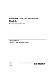
Agilent E1446A
Summing Amplifier/DAC Module
User’s Manual and SCPI Programming Guide
Where to Find it - Online and Printed Information:
System installation (hardware/software)............. VXIbus Configuration Guide*
Agilent VIC (VXI installation software)*
Module configuration and wiring........................ This Manual
SCPI programming.............................................. This Manual
SCPI example programs...................................... This Manual
SCPI command reference ................................... This Manual
Register-Based Programming ............................. This Manual
VXIplug&play programming ............................. VXIplug&play Online Help
VXIplug&play example programs...................... VXIplug&play Online Help
VXIplug&play function reference ...................... VXIplug&play Online Help
Soft Front Panel information............................... VXIplug&play Online Help
VISA language information ................................ Agilent VISA User’s Guide
Agilent VEE programming information ............. Agilent VEE User’s Manual
*Supplied with Agilent Command Modules, Embedded Controllers, and VXLink.
*E1446-90001*
Manual Part Number: E1446-90001
Printed in Malaysia E0506
Table of Contents
Warranty . . . . . . . . . .
Safety Symbols . . . . . .
WARNINGS . . . . . . . .
Declaration of Conformity .
.
.
.
.
.
.
.
.
.
.
.
.
.
.
.
.
.
.
.
.
.
.
.
.
.
.
.
.
.
.
.
.
.
.
.
.
.
.
.
.
.
.
.
.
.
.
.
.
.
.
.
.
.
.
.
.
.
.
.
.
.
.
.
.
.
.
.
.
.
.
.
.
.
.
.
.
.
.
.
.
.
.
.
.
.
.
.
.
.
.
.
.
.
.
.
.
.
.
.
.
.
.
.
.
.
.
.
.
.
.
.
.
.
.
.
.
.
.
.
.
.
.
.
.
.
.
.
.
5
6
6
7
Chapter Contents . . . . . . . . . . . . . . . . . .
General Description . . . . . . . . . . . . . . . .
Features . . . . . . . . . . . . . . . . . . . . .
Preparation for Use . . . . . . . . . . . . . . . .
Configuring the Amplifier . . . . . . . . . . .
Installing the Amplifier . . . . . . . . . . . . .
Addressing the Amplifier . . . . . . . . . . .
Downloading the Agilent E1446A SCPI Driver
Basic Operation . . . . . . . . . . . . . . . . . .
Amplifier Block Diagram . . . . . . . . . . .
Output . . . . . . . . . . . . . . . . . . . . .
.
.
.
.
.
.
.
.
.
.
.
.
.
.
.
.
.
.
.
.
.
.
.
.
.
.
.
.
.
.
.
.
.
.
.
.
.
.
.
.
.
.
.
.
.
.
.
.
.
.
.
.
.
.
.
.
.
.
.
.
.
.
.
.
.
.
.
.
.
.
.
.
.
.
.
.
.
.
.
.
.
.
.
.
.
.
.
.
.
.
.
.
.
.
.
.
.
.
.
.
.
.
.
.
.
.
.
.
.
.
.
.
.
.
.
.
.
.
.
.
.
.
.
.
.
.
.
.
.
.
.
.
.
.
.
.
.
.
.
.
.
.
.
.
.
.
.
.
.
.
.
.
.
.
.
.
.
.
.
.
.
.
.
.
.
.
.
.
.
.
.
.
.
.
.
.
.
.
.
.
.
.
.
.
.
.
.
.
.
.
.
.
.
.
.
.
.
.
.
.
.
.
.
.
.
.
.
.
.
.
.
.
.
.
.
.
.
.
.
.
1-1
1-1
1-1
1-3
1-3
1-4
1-5
1-7
1-8
1-9
1-9
Chapter Contents . . . . . . . . . . . . . . . . . . . . . . . . . .
Instrument and Programming Languages . . . . . . . . . . . . .
SCPI Programming . . . . . . . . . . . . . . . . . . . . . . .
Command Coupling . . . . . . . . . . . . . . . . . . . . . .
Instrument Driver and Example Programs Disks . . . . . . .
System Configuration . . . . . . . . . . . . . . . . . . . . .
Introductory Programs . . . . . . . . . . . . . . . . . . . . . . .
Executing the Self-Test . . . . . . . . . . . . . . . . . . . .
Resetting and Clearing the Agilent E1446A . . . . . . . . . .
Querying the Power-on/Reset Configuration . . . . . . . . .
Example Programs . . . . . . . . . . . . . . . . . . . . . . . . .
Generating and Amplifying Sine Waves . . . . . . . . . . . . .
Amplifying Sine Waves (Agilent E1445A Commander) . . .
Amplifying Sine Waves (Agilent E1405 Commander) . . . .
Setting the Input Impedance . . . . . . . . . . . . . . . . . . . .
Setting the Input Impedance (Agilent E1445A Commander) .
Setting Input Impedance (Agilent E1405B Commander) . . .
Setting DC Voltage Offsets . . . . . . . . . . . . . . . . . . . .
Setting DC Offsets (Agilent E1445A Commander) . . . . . .
Setting DC Offsets (Agilent E1405 Commander) . . . . . . .
Using the Differential (small signal) Outputs . . . . . . . . . . .
Using the Differential Outputs (Agilent E1445A Commander)
Using the Differential Outputs (Agilent E1405 Commander) .
Summing Two Signals . . . . . . . . . . . . . . . . . . . . . . .
.
.
.
.
.
.
.
.
.
.
.
.
.
.
.
.
.
.
.
.
.
.
.
.
.
.
.
.
.
.
.
.
.
.
.
.
.
.
.
.
.
.
.
.
.
.
.
.
.
.
.
.
.
.
.
.
.
.
.
.
.
.
.
.
.
.
.
.
.
.
.
.
.
.
.
.
.
.
.
.
.
.
.
.
.
.
.
.
.
.
.
.
.
.
.
.
.
.
.
.
.
.
.
.
.
.
.
.
.
.
.
.
.
.
.
.
.
.
.
.
.
.
.
.
.
.
.
.
.
.
.
.
.
.
.
.
.
.
.
.
.
.
.
.
.
.
.
.
.
.
.
.
.
.
.
.
.
.
.
.
.
.
.
.
.
.
.
.
.
.
.
.
.
.
.
.
.
.
.
.
.
.
.
.
.
.
.
.
.
.
.
.
.
.
.
.
.
.
.
.
.
.
.
.
.
.
.
.
.
.
.
.
.
.
.
.
.
.
.
.
.
.
.
.
.
.
.
.
.
.
.
.
.
.
.
.
.
.
.
.
.
.
.
.
.
.
.
.
.
.
.
.
.
.
.
.
.
.
.
.
.
.
.
.
.
.
.
.
.
.
.
.
.
.
.
.
.
.
.
.
.
.
.
.
.
.
.
.
2-1
2-1
2-1
2-2
2-4
2-4
2-5
2-5
2-6
2-6
2-8
2-9
2-9
2-12
2-14
2-14
2-17
2-20
2-20
2-23
2-26
2-26
2-29
2-31
1. Getting Started
2. Programming the Agilent E1446A
Agilent E1446A User’s Manual Contents
1
3. Command Reference
Chapter Contents . . . . . . . . . . . . . . . . . .
Command Types . . . . . . . . . . . . . . . . . .
Common Command Format . . . . . . . . . .
SCPI Command Format . . . . . . . . . . . . . .
Command Separator . . . . . . . . . . . . . .
Abbreviated Commands . . . . . . . . . . . .
Implied (Optional) Keywords . . . . . . . . .
SCPI Command Parameters . . . . . . . . . . . .
Parameter Types, Explanations, and Examples
Querying Parameter Settings . . . . . . . . . .
SCPI Command Execution . . . . . . . . . . . .
Command Coupling . . . . . . . . . . . . . .
Linking Commands . . . . . . . . . . . . . .
SCPI Command Reference . . . . . . . . . . . .
Agilent E1446A/E1445A
INPut[1] . . . . . . . . . . . . . . . . . . . . . .
:ATTenuation . . . . . . . . . . . . . . . . . .
:IMPedance . . . . . . . . . . . . . . . . . . .
INPut2 . . . . . . . . . . . . . . . . . . . . . . .
:ATTenuation . . . . . . . . . . . . . . . . . .
:IMPedance . . . . . . . . . . . . . . . . . . .
OUTPut2 . . . . . . . . . . . . . . . . . . . . . .
:ATTenuation . . . . . . . . . . . . . . . . . .
:IMPedance . . . . . . . . . . . . . . . . . . .
:OVERload? . . . . . . . . . . . . . . . . . .
[:STATe] . . . . . . . . . . . . . . . . . . . .
[:STATe]:ACTual? . . . . . . . . . . . . . . .
OUTPut3 . . . . . . . . . . . . . . . . . . . . . .
:IMPedance . . . . . . . . . . . . . . . . . . .
OUTPut4 . . . . . . . . . . . . . . . . . . . . . .
:IMPedance . . . . . . . . . . . . . . . . . . .
SOURce2:VOLTage . . . . . . . . . . . . . . . .
[:LEVel][:IMMediate]:OFFSet . . . . . . . .
STATus . . . . . . . . . . . . . . . . . . . . . .
:OPERation|QUEStionable:CONDition? . . .
:OPERation|QUEStionable:ENABle . . . . . .
:OPERation|QUEStionable[:EVENt]? . . . . .
:OPERation|QUEStionable:NTRansition . . .
:OPERation|QUEStionable:PTRansition . . .
:PRESet . . . . . . . . . . . . . . . . . . . . .
SYSTem . . . . . . . . . . . . . . . . . . . . . .
:ERRor? . . . . . . . . . . . . . . . . . . . . .
:VERSion? . . . . . . . . . . . . . . . . . . .
Agilent E1446A/E1405/06
DISPlay . . . . . . . . . . . . . . . . . . . . . .
:MONitor[:STATe] . . . . . . . . . . . . . . .
INPut[1] . . . . . . . . . . . . . . . . . . . . . .
:ATTenuation . . . . . . . . . . . . . . . . . .
:IMPedance . . . . . . . . . . . . . . . . . . .
2
Agilent E1446A User’s Manual Contents
.
.
.
.
.
.
.
.
.
.
.
.
.
.
.
.
.
.
.
.
.
.
.
.
.
.
.
.
.
.
.
.
.
.
.
.
.
.
.
.
.
.
.
.
.
.
.
.
.
.
.
.
.
.
.
.
.
.
.
.
.
.
.
.
.
.
.
.
.
.
.
.
.
.
.
.
.
.
.
.
.
.
.
.
.
.
.
.
.
.
.
.
.
.
.
.
.
.
.
.
.
.
.
.
.
.
.
.
.
.
.
.
.
.
.
.
.
.
.
.
.
.
.
.
.
.
.
.
.
.
.
.
.
.
.
.
.
.
.
.
.
.
.
.
.
.
.
.
.
.
.
.
.
.
.
.
.
.
.
.
.
.
.
.
.
.
.
.
.
.
.
.
.
.
.
.
.
.
.
.
.
.
.
.
.
.
.
.
.
.
.
.
.
.
.
.
.
.
.
.
.
.
.
.
.
.
.
.
.
.
.
.
.
.
.
.
.
.
.
.
.
.
.
.
.
.
.
.
.
.
.
.
.
.
.
.
.
.
.
.
.
.
.
.
.
.
.
.
.
.
.
.
.
.
.
.
.
.
.
.
.
.
.
.
.
.
.
.
.
.
.
.
.
.
.
.
.
.
.
.
3-1
3-2
3-2
3-2
3-3
3-3
3-3
3-4
3-4
3-5
3-5
3-5
3-6
3-6
.
.
.
.
.
.
.
.
.
.
.
.
.
.
.
.
.
.
.
.
.
.
.
.
.
.
.
.
.
.
.
.
.
.
.
.
.
.
.
.
.
.
.
.
.
.
.
.
.
.
.
.
.
.
.
.
.
.
.
.
.
.
.
.
.
.
.
.
.
.
.
.
.
.
.
.
.
.
.
.
.
.
.
.
.
.
.
.
.
.
.
.
.
.
.
.
.
.
.
.
.
.
.
.
.
.
.
.
.
.
.
.
.
.
.
.
.
.
.
.
.
.
.
.
.
.
.
.
.
.
.
.
.
.
.
.
.
.
.
.
.
.
.
.
.
.
.
.
.
.
.
.
.
.
.
.
.
.
.
.
.
.
.
.
.
.
.
.
.
.
.
.
.
.
.
.
.
.
.
.
.
.
.
.
.
.
.
.
.
.
.
.
.
.
.
.
.
.
.
.
.
.
.
.
.
.
.
.
.
.
.
.
.
.
.
.
.
.
.
.
.
.
.
.
.
.
.
.
.
.
.
.
.
.
.
.
.
.
.
.
.
.
.
.
.
.
.
.
.
.
.
.
.
.
.
.
.
.
.
.
.
.
.
.
.
.
.
.
.
.
.
.
.
.
.
.
.
.
.
.
.
.
.
.
.
.
.
.
.
.
.
.
.
.
.
.
.
.
.
.
.
.
.
.
.
.
.
.
.
.
.
.
.
.
.
.
.
.
.
.
.
.
.
.
.
.
.
.
.
.
.
.
.
.
.
.
.
.
.
.
.
.
.
.
.
.
.
.
.
.
.
.
.
.
.
.
.
.
.
.
.
.
.
.
.
.
.
.
.
.
.
.
.
.
.
.
.
.
.
.
.
.
.
.
.
.
.
.
.
.
.
.
.
.
.
.
.
.
.
.
.
.
.
.
.
.
.
.
.
.
.
.
.
.
.
.
.
.
.
.
.
.
.
.
.
.
.
.
.
.
.
.
.
.
.
.
.
.
.
.
.
.
.
.
.
.
.
.
.
.
.
.
.
.
.
.
.
.
.
.
.
.
.
.
.
.
.
.
.
.
.
.
.
.
.
.
.
.
.
.
.
.
.
.
.
.
.
.
.
.
.
.
.
.
.
.
.
.
.
.
.
.
.
.
.
.
.
.
.
.
.
.
.
.
.
.
.
.
.
.
.
.
.
.
.
.
.
.
.
.
.
.
.
.
.
.
.
.
.
.
.
.
.
.
.
.
.
.
.
.
.
.
.
.
.
.
.
.
.
.
3-7
3-7
3-7
3-9
3-9
3-9
3-11
3-11
3-12
3-12
3-13
3-13
3-15
3-15
3-16
3-16
3-17
3-17
3-18
3-18
3-19
3-19
3-20
3-20
3-21
3-22
3-22
3-22
.
.
.
.
.
.
.
.
.
.
.
.
.
.
.
.
.
.
.
.
.
.
.
.
.
.
.
.
.
.
.
.
.
.
.
.
.
.
.
.
.
.
.
.
.
.
.
.
.
.
.
.
.
.
.
.
.
.
.
.
.
.
.
.
.
.
.
.
.
.
.
.
.
.
.
.
.
.
.
.
.
.
.
.
.
.
.
.
.
.
.
.
.
.
.
.
.
.
.
.
3-7
3-7
3-8
3-8
3-8
INPut2 . . . . . . . . . . . . . . . . . . . .
:ATTenuation . . . . . . . . . . . . . . .
:IMPedance . . . . . . . . . . . . . . . .
OUTPut1 . . . . . . . . . . . . . . . . . . .
:ATTenuation . . . . . . . . . . . . . . .
:IMPedance . . . . . . . . . . . . . . . .
:OVERload? . . . . . . . . . . . . . . .
[:STATe] . . . . . . . . . . . . . . . . .
[:STATe]:ACTual? . . . . . . . . . . . .
OUTPut2 . . . . . . . . . . . . . . . . . . .
:IMPedance . . . . . . . . . . . . . . . .
OUTPut3 . . . . . . . . . . . . . . . . . . .
:IMPedance . . . . . . . . . . . . . . . .
SOURce:VOLTage . . . . . . . . . . . . .
[:LEVel][:IMMediate]:OFFSet . . . . .
STATus . . . . . . . . . . . . . . . . . . .
:OPERation|QUEStionable:CONDition?
:OPERation|QUEStionable:ENABle . . .
:OPERation|QUEStionable[:EVENt]? . .
:OPERation|QUEStionable:NTRansition
:OPERation|QUEStionable:PTRansition
:PRESet . . . . . . . . . . . . . . . . . .
SYSTem . . . . . . . . . . . . . . . . . . .
:ERRor? . . . . . . . . . . . . . . . . . .
:VERSion? . . . . . . . . . . . . . . . .
IEEE-488.2 Common Commands . . . . . .
*CLS . . . . . . . . . . . . . . . . . . .
*DMC . . . . . . . . . . . . . . . . . .
*EMC and *EMC? . . . . . . . . . . . .
*ESE and *ESE? . . . . . . . . . . . . .
*ESR? . . . . . . . . . . . . . . . . . .
*GMC? . . . . . . . . . . . . . . . . . .
*IDN? . . . . . . . . . . . . . . . . . . .
*LMC? . . . . . . . . . . . . . . . . . .
*LRN? . . . . . . . . . . . . . . . . . .
*OPC . . . . . . . . . . . . . . . . . . .
*OPC? . . . . . . . . . . . . . . . . . .
*PMC . . . . . . . . . . . . . . . . . . .
*RCL . . . . . . . . . . . . . . . . . . .
*RMC . . . . . . . . . . . . . . . . . . .
*RST . . . . . . . . . . . . . . . . . . .
*SAV . . . . . . . . . . . . . . . . . . .
*SRE and *SRE? . . . . . . . . . . . . .
*STB? . . . . . . . . . . . . . . . . . .
*TST? . . . . . . . . . . . . . . . . . . .
*WAI . . . . . . . . . . . . . . . . . . .
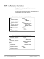
SCPI Conformance Information . . . . . . .
.
.
.
.
.
.
.
.
.
.
.
.
.
.
.
.
.
.
.
.
.
.
.
.
.
.
.
.
.
.
.
.
.
.
.
.
.
.
.
.
.
.
.
.
.
.
.
.
.
.
.
.
.
.
.
.
.
.
.
.
.
.
.
.
.
.
.
.
.
.
.
.
.
.
.
.
.
.
.
.
.
.
.
.
.
.
.
.
.
.
.
.
.
.
.
.
.
.
.
.
.
.
.
.
.
.
.
.
.
.
.
.
.
.
.
.
.
.
.
.
.
.
.
.
.
.
.
.
.
.
.
.
.
.
.
.
.
.
.
.
.
.
.
.
.
.
.
.
.
.
.
.
.
.
.
.
.
.
.
.
.
.
.
.
.
.
.
.
.
.
.
.
.
.
.
.
.
.
.
.
.
.
.
.
.
.
.
.
.
.
.
.
.
.
.
.
.
.
.
.
.
.
.
.
.
.
.
.
.
.
.
.
.
.
.
.
.
.
.
.
.
.
.
.
.
.
.
.
.
.
.
.
.
.
.
.
.
.
.
.
.
.
.
.
.
.
.
.
.
.
.
.
.
.
.
.
.
.
.
.
.
.
.
.
.
.
.
.
.
.
.
.
.
.
.
.
.
.
.
.
.
.
.
.
.
.
.
.
.
.
.
.
.
.
.
.
.
.
.
.
.
.
.
.
.
.
.
.
.
.
.
.
.
.
.
.
.
.
.
.
.
.
.
.
.
.
.
.
.
.
.
.
.
.
.
.
.
.
.
.
.
.
.
.
.
.
.
.
.
.
.
.
.
.
.
.
.
.
.
.
.
.
.
.
.
.
.
.
.
.
.
.
.
.
.
.
.
.
.
.
.
.
.
.
.
.
.
.
.
.
.
.
.
.
.
.
.
.
.
.
.
.
.
.
.
.
.
.
.
.
.
.
.
.
.
.
.
.
.
.
.
.
.
.
.
.
.
.
.
.
.
.
.
.
.
.
.
.
.
.
.
.
.
.
.
.
.
.
.
.
.
.
.
.
.
.
.
.
.
.
.
.
.
.
.
.
.
.
.
.
.
.
.
.
.
.
.
.
.
.
.
.
.
.
.
.
.
.
.
.
.
.
.
.
.
.
.
.
.
.
.
.
.
.
.
.
.
.
.
.
.
.
.
.
.
.
.
.
.
.
.
.
.
.
.
.
.
.
.
.
.
.
.
.
.
.
.
.
.
.
.
.
.
.
.
.
.
.
.
.
.
.
.
.
.
.
.
.
.
.
.
.
.
.
.
.
.
.
.
.
.
.
.
.
.
.
.
.
.
.
.
.
.
.
.
.
.
.
.
.
.
.
.
.
.
.
.
.
.
.
.
.
.
.
.
.
.
.
.
.
.
.
.
.
.
.
.
.
.
.
.
.
.
.
.
.
.
.
.
.
.
.
.
.
.
.
.
.
.
.
.
.
.
.
.
.
.
.
.
.
.
.
.
.
.
.
.
.
.
.
.
.
.
.
.
.
.
.
.
.
.
.
.
.
.
.
.
.
.
.
.
.
.
.
.
.
.
.
.
.
.
.
.
.
.
.
.
.
.
.
.
.
.
.
.
.
.
.
.
.
.
.
.
.
.
.
.
.
.
.
.
.
.
.
.
.
.
.
.
.
.
.
.
.
.
.
.
.
.
.
.
.
.
.
.
.
.
.
.
.
.
.
.
.
.
.
.
.
.
.
.
.
.
.
.
.
.
.
.
.
.
.
.
.
.
.
.
.
.
.
.
.
.
.
.
.
.
.
.
.
.
.
.
.
.
.
.
.
.
.
.
.
.
.
.
.
.
.
.
.
.
.
.
.
.
.
.
.
.
.
.
.
.
.
.
.
.
.
.
.
.
.
.
.
.
.
.
.
.
.
.
.
.
.
.
.
.
.
.
.
.
.
.
.
.
.
.
.
.
.
.
.
.
.
.
.
.
.
.
.
.
.
.
.
.
.
.
.
.
.
.
.
.
.
.
.
.
.
.
.
.
.
.
.
.
.
.
.
.
.
.
.
.
.
.
.
.
.
.
.
.
.
.
.
.
.
.
.
.
.
.
.
.
.
.
.
.
.
.
.
.
.
.
.
.
.
.
.
.
.
.
.
.
.
.
.
.
.
.
.
.
.
.
.
.
.
.
.
.
.
.
.
.
.
.
.
.
.
.
.
.
.
.
.
.
.
.
.
.
.
.
.
.
.
.
.
.
.
.
.
.
.
.
.
.
.
.
.
.
.
.
.
.
.
.
.
.
.
.
.
.
.
.
.
.
.
.
.
.
.
.
.
.
.
.
.
.
.
.
.
.
.
.
.
.
.
.
.
.
.
.
.
.
.
.
.
.
.
.
.
.
.
.
.
.
.
.
.
.
.
.
.
.
.
.
.
.
.
.
.
.
.
.
.
.
.
.
.
.
.
.
3-10
3-10
3-10
3-12
3-12
3-12
3-13
3-14
3-14
3-15
3-15
3-16
3-16
3-17
3-17
3-18
3-18
3-19
3-19
3-20
3-20
3-21
3-22
3-22
3-22
3-25
3-26
3-26
3-27
3-27
3-28
3-28
3-29
3-29
3-30
3-30
3-30
3-31
3-31
3-31
3-32
3-32
3-33
3-33
3-34
3-34
3-35
Agilent E1446A User’s Manual Contents
3
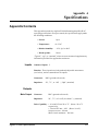
A. Specifications
Appendix Contents . . . . . .
Inputs . . . . . . . . . . . .
Outputs . . . . . . . . . . .
Gain Characteristics . . . .
Offset . . . . . . . . . . . .
AC Characteristics . . . . .
General VXI Characteristics
.
.
.
.
.
.
.
.
.
.
.
.
.
.
.
.
.
.
.
.
.
.
.
.
.
.
.
.
.
.
.
.
.
.
.
.
.
.
.
.
.
.
.
.
.
.
.
.
.
.
.
.
.
.
.
.
.
.
.
.
.
.
.
.
.
.
.
.
.
.
.
.
.
.
.
.
.
.
.
.
.
.
.
.
.
.
.
.
.
.
.
.
.
.
.
.
.
.
.
.
.
.
.
.
.
.
.
.
.
.
.
.
.
.
.
.
.
.
.
.
.
.
.
.
.
.
.
.
.
.
.
.
.
.
.
.
.
.
.
.
.
.
.
.
.
.
.
.
.
.
.
.
.
.
.
.
.
.
.
.
.
.
.
.
.
.
.
.
.
.
.
.
.
.
.
.
.
.
.
.
.
.
.
.
.
.
.
.
.
.
.
.
.
.
.
.
.
.
.
.
.
.
.
.
.
.
.
.
.
.
A-1
A-1
A-1
A-2
A-2
A-3
A-3
B. Error Messages
Table B-1. Agilent E1446A Error Messages . . . . . . . . . . . . . . . . . . . . . . B-2
Table B-2. Agilent E1446A Settings Conflict Errors with the Agilent E1405/06 . . . B-4
Table B-3. Agilent E1446A Settings Conflict Errors with the Agilent E1445A . . . B-4
C. Register-Based Programming
Appendix Contents . . . . . . . . . . . . . . . . . . . .
Register Addressing . . . . . . . . . . . . . . . . . . . .
The Base Address . . . . . . . . . . . . . . . . . . .
Computer Configurations . . . . . . . . . . . . . . . . .
Throughput Speed . . . . . . . . . . . . . . . . . . .
Embedded Computer Programming (C-Size Systems)
IBASIC Programming . . . . . . . . . . . . . . . . .
External Computer Programming . . . . . . . . . . .
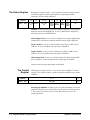
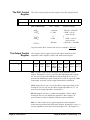
Register Descriptions . . . . . . . . . . . . . . . . . . .
The READ Registers . . . . . . . . . . . . . . . . . .
The ID Register . . . . . . . . . . . . . . . . . . . . .
The Device Type Register . . . . . . . . . . . . . . .
The READ/WRITE Registers . . . . . . . . . . . . .
The Status Register . . . . . . . . . . . . . . . . . .
The Control Register . . . . . . . . . . . . . . . . . .
The DAC Control Register . . . . . . . . . . . . . . .
The Output Control Register . . . . . . . . . . . . . .
The Input Attenuation Register . . . . . . . . . . . .
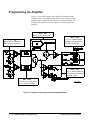
Programming the Amplifier . . . . . . . . . . . . . . . .
Program Sequence and Execution . . . . . . . . . . .
Example Programs . . . . . . . . . . . . . . . . . . . . .
System Configuration . . . . . . . . . . . . . . . . .
Amplifying a Sine Wave . . . . . . . . . . . . . . . .
Setting the (amplifier) Input Impedance . . . . . . . .
Setting a DC Voltage Offset . . . . . . . . . . . . . .
Using the Differential (small signal) Outputs . . . . .
Summing Two Signals . . . . . . . . . . . . . . . . .
Example Subprograms . . . . . . . . . . . . . . . . .
Index
4
Agilent E1446A User’s Manual Contents
.
.
.
.
.
.
.
.
.
.
.
.
.
.
.
.
.
.
.
.
.
.
.
.
.
.
.
.
.
.
.
.
.
.
.
.
.
.
.
.
.
.
.
.
.
.
.
.
.
.
.
.
.
.
.
.
.
.
.
.
.
.
.
.
.
.
.
.
.
.
.
.
.
.
.
.
.
.
.
.
.
.
.
.
.
.
.
.
.
.
.
.
.
.
.
.
.
.
.
.
.
.
.
.
.
.
.
.
.
.
.
.
.
.
.
.
.
.
.
.
.
.
.
.
.
.
.
.
.
.
.
.
.
.
.
.
.
.
.
.
.
.
.
.
.
.
.
.
.
.
.
.
.
.
.
.
.
.
.
.
.
.
.
.
.
.
.
.
.
.
.
.
.
.
.
.
.
.
.
.
.
.
.
.
.
.
.
.
.
.
.
.
.
.
.
.
.
.
.
.
.
.
.
.
.
.
.
.
.
.
.
.
.
.
.
.
.
.
.
.
.
.
.
.
.
.
.
.
.
.
.
.
.
.
.
.
.
.
.
.
.
.
.
.
.
.
.
.
.
.
.
.
.
.
.
.
.
.
.
.
.
.
.
.
.
.
.
.
.
.
.
.
.
.
.
.
.
.
.
.
.
.
.
.
.
.
.
.
.
.
.
.
.
.
.
.
.
.
.
.
.
.
.
.
.
.
.
.
.
.
.
.
.
.
.
.
.
.
.
.
.
.
.
.
.
.
.
.
.
.
.
.
.
.
.
.
.
.
.
.
.
.
.
.
.
.
.
.
.
.
.
.
.
.
.
.
.
.
.
.
.
.
.
.
.
.
.
.
.
.
.
.
.
.
.
.
.
.
.
.
.
.
.
.
.
.
.
.
.
.
.
.
.
.
.
.
.
.
.
.
.
.
.
.
.
.
.
.
.
.
.
.
.
.
.
.
.
.
.
.
.
.
.
.
.
.
.
.
.
.
.
.
.
.
.
.
.
.
.
.
.
.
.
.
.
.
.
.
C-1
C-1
C-1
C-4
C-4
C-4
C-4
C-5
C-6
C-6
C-6
C-7
C-7
C-8
C-8
C-9
C-9
C-10
C-12
C-14
C-17
C-17
C-18
C-19
C-21
C-23
C-24
C-26
Certification
Agilent Technologies certifies that this product met its published specifications at the time of shipment from the factory. Agilent
Technologies further certifies that its calibration measurements are traceable to the United States National Institute of Standards and
Technology (formerly National Bureau of Standards), to the extent allowed by that organization’s calibration facility, and to the calibration
facilities of other International Standards Organization members.
Warranty
This Agilent Technologies product is warranted against defects in materials and workmanship for a period of one (1) year from date of
shipment. Duration and conditions of warranty for this product may be superseded when the product is integrated into (becomes a part
of) other Agilent products. During the warranty period, Agilent Technologies will, at its option, either repair or replace products which
prove to be defective.
For warranty service or repair, this product must be returned to a service facility designated by Agilent Technologies. Buyer shall prepay
shipping charges to Agilent and Agilent shall pay shipping charges to return the product to Buyer. However, Buyer shall pay all shipping
charges, duties, and taxes for products returned to Agilent from another country.
Agilent warrants that its software and firmware designated by Agilent for use with a product will execute its programming instructions
when properly installed on that product. Agilent does not warrant that the operation of the product, or software, or firmware will be
uninterrupted or error free.
Limitation Of Warranty
The foregoing warranty shall not apply to defects resulting from improper or inadequate maintenance by Buyer, Buyer-supplied products
or interfacing, unauthorized modification or misuse, operation outside of the environmental specifications for the product, or improper site
preparation or maintenance.
The design and implementation of any circuit on this product is the sole responsibility of the Buyer. Agilent does not warrant the Buyer’s
circuitry or malfunctions of Agilent products that result from the Buyer’s circuitry. In addition, Agilent does not warrant any damage that
occurs as a result of the Buyer’s circuit or any defects that result from Buyer-supplied products.
NO OTHER WARRANTY IS EXPRESSED OR IMPLIED. Agilent SPECIFICALLY DISCLAIMS THE IMPLIED WARRANTIES
OF MERCHANTABILITY AND FITNESS FOR A PARTICULAR PURPOSE.
Exclusive Remedies
THE REMEDIES PROVIDED HEREIN ARE BUYER’S SOLE AND EXCLUSIVE REMEDIES. Agilent SHALL NOT BE LIABLE
FOR ANY DIRECT, INDIRECT, SPECIAL, INCIDENTAL, OR CONSEQUENTIAL DAMAGES, WHETHER BASED ON CONTRACT, TORT, OR ANY OTHER LEGAL THEORY.
Notice
The information contained in this document is subject to change without notice. Agilent Technologies MAKES NO WARRANTY OF
ANY KIND WITH REGARD TO THIS MATERIAL, INCLUDING, BUT NOT LIMITED TO, THE IMPLIED WARRANTIES OF
MERCHANTABILITY AND FITNESS FOR A PARTICULAR PURPOSE. Agilent shall not be liable for errors contained herein or for
incidental or consequential damages in connection with the furnishing, performance or use of this material. This document contains
proprietary information which is protected by copyright. All rights are reserved. No part of this document may be photocopied, reproduced,
or translated to another language without the prior written consent of Agilent Technologies, Inc. Agilent assumes no responsibility for the
use or reliability of its software on equipment that is not furnished by Agilent.
U.S. Government Restricted Rights
The Software and Documentation have been developed entirely at private expense. They are delivered and licensed as "commercial
computer software" as defined in DFARS 252.227- 7013 (Oct 1988), DFARS 252.211-7015 (May 1991) or DFARS 252.227-7014 (Jun
1995), as a "commercial item" as defined in FAR 2.101(a), or as "Restricted computer software" as defined in FAR 52.227-19 (Jun 1987)(or
any equivalent agency regulation or contract clause), whichever is applicable. You have only those rights provided for such Software and
Documentation by the applicable FAR or DFARS clause or the Agilent standard software agreement for the product involved.
Agilent E1446A Summing Amplifier/DAC User’s Manual
Edition 1 Rev 2
Copyright © 1992-2006 Agilent Technologies, Inc. All Rights Reserved.
Agilent E1446A Summing Amplifier/DAC User’s Manual
5
Printing History
The Printing History shown below lists all Editions and Updates of this manual and the printing date(s). The first printing of the manual
is Edition 1. The Edition number increments by 1 whenever the manual is revised. Updates, which are issued between Editions, contain
replacement pages to correct the current Edition of the manual. Updates are numbered sequentially starting with Update 1. When a new
Edition is created, it contains all the Update information for the previous Edition. Each new Edition or Update also includes a revised copy
of this printing history page. Many product updates or revisions do not require manual changes and, conversely, manual corrections may
be done without accompanying product changes. Therefore, do not expect a one-to-one correspondence between product updates and
manual updates.
Edition 1 (Part Number E1446-90001). . . . . . . . . . . . . . . . . . . . . . . . . May 1992
Edition 1 Rev 2 (Part Number E1446-90001) . . . . . . . . . . . . . . . . . . . May 2006
Safety Symbols
Instruction manual symbol affixed to product.
Indicates that the user must refer to the manual for specific WARNING or CAUTION
information to avoid personal injury or damage to the product.
Alternating current (AC).
Direct current (DC).
Indicates hazardous voltages.
Indicates the field wiring terminal that must
be connected to earth ground before operating
the equipment—protects against electrical
shock in case of fault.
or
Frame or chassis ground terminal—typically
connects to the equipment’s metal frame.
WARNING
CAUTION
Calls attention to a procedure, practice, or condition that could cause bodily injury or death.
Calls attention to a procedure, practice, or condition that could possibly cause damage to
equipment or permanent loss of data.
WARNINGS
The following general safety precautions must be observed during all phases of operation, service, and repair of this product.
Failure to comply with these precautions or with specific warnings elsewhere in this manual violates safety standards of design,
manufacture, and intended use of the product. Agilent Technologies assumes no liability for the customer’s failure to comply with
these requirements.
Ground the equipment: For Safety Class 1 equipment (equipment having a protective earth terminal), an uninterruptible safety earth
ground must be provided from the mains power source to the product input wiring terminals or supplied power cable.
DO NOT operate the product in an explosive atmosphere or in the presence of flammable gases or fumes.
For continued protection against fire, replace the line fuse(s) only with fuse(s) of the same voltage and current rating and type.
DO NOT use repaired fuses or short-circuited fuse holders.
Keep away from live circuits: Operating personnel must not remove equipment covers or shields. Procedures involving the removal of
covers or shields are for use by service-trained personnel only. Under certain conditions, dangerous voltages may exist even with the
equipment switched off. To avoid dangerous electrical shock, DO NOT perform procedures involving cover or shield removal unless you
are qualified to do so.
DO NOT operate damaged equipment: Whenever it is possible that the safety protection features built into this product have been
impaired, either through physical damage, excessive moisture, or any other reason, REMOVE POWER and do not use the product until
safe operation can be verified by service-trained personnel. If necessary, return the product to an Agilent Technologies Sales and Service
Office for service and repair to ensure that safety features are maintained.
DO NOT service or adjust alone: Do not attempt internal service or adjustment unless another person, capable of rendering first aid and
resuscitation, is present.
DO NOT substitute parts or modify equipment: Because of the danger of introducing additional hazards, do not install substitute parts
or perform any unauthorized modification to the product. Return the product to an Agilent Technologies Sales and Service Office for
service and repair to ensure that safety features are maintained.
6
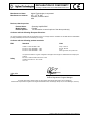
Agilent E1446A Summing Amplifier/DAC User’s Manual
DECLARATION OF CONFORMITY
According to ISO/IEC Guide 22 and CEN/CENELEC EN 45014
Manufacturer’s Name:
Manufacturer’s Address:
Agilent Technologies, Incorporated
th
815 – 14 St. SW
Loveland, Colorado 80537
USA
Declares, that the product
Product Name:
Model Number:
Product Options:
Summing Amplifier/DAC
E1446A
This declaration covers all options of the above product(s).
Conforms with the following European Directives:
The product herewith complies with the requirements of the Low Voltage Directive 73/23/EEC and the EMC Directive 89/336/EEC
(including 93/68/EEC) and carries the CE Marking accordingly.
Conforms with the following product standards:
EMC
Safety
Standard
Limit
CISPR 11:1990 / EN 55011:1991
IEC 801-2 :1991 / EN50082-1 : 1992
IEC 801-3 :1984 / EN50082-1 : 1992
IEC 801-4 :1988 / EN50082-1 : 1992
Group 1 Class A
4kV CD, 8kV AD
3 V/m
0.5kV signal lines, 1kV power lines
The produt was tested in a typical configuration with Agilent Technologies or Hewlett-Packard Company test
systems
IEC 1010-1:1990+A2:1996 / EN 61010-1:1993
Canada: CSA C22.2 No. 1010.1:1992
UL 3111-1
3 May 2001
Date
Ray Corson
Product Regulations Program Manager
For further information, please contact your local Agilent Technologies sales office, agent or distributor.
Authorized EU-representative: Agilent Technologies Deutschland GmbH, Herrenberger Straβe 130, D 71034 Böblingen, Germany
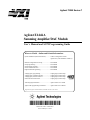
Agilent E1446A Summing Amplifier/DAC User’s Manual 7
Notes
8
Agilent E1446A Summing Amplifier/DAC User’s Manual
Chapter 1
Getting Started
Chapter Contents
This chapter provides a description of the Agilent E1446A Summing
Amplifier/DAC module and describes how to install, configure, and
program it. The main sections of this chapter are:
• General Description . . . . . . . . . . . . . . . . . . . . . . . . . . . . . . . 1-1
• Preparation for Use . . . . . . . . . . . . . . . . . . . . . . . . . . . . . . 1-3
• Basic Operation . . . . . . . . . . . . . . . . . . . . . . . . . . . . . . . . . . 1-8
General Description
The Agilent E1446A Summing Amplifier/DAC is a multifunction
register-based VXIbus C-size module. It is designed to work with either the
Agilent E1445A Arbitrary Function Generator (AFG) or to function
stand-alone with the Agilent E1405/06 Command Module as a power
amplifier/DAC. The Agilent E1446A allows you to amplify or attenuate,
sum, and offset signals via the main output. The differential (small signal)
output allows you to invert a signal.
Features
The Agilent E1446A Summing Amplifier/DAC has the following features:
• provides two input channels that have:
– independently controlled input impedance
– independently controlled input attenuators of 0 to 31 dB in 1 dB
steps.
• sums the two input channels.
• provides output channels that include:
– single-ended main output (power amplifier)
– differential (small signal) output; one inverting, one
non-inverting.
functions as stand-alone offset DAC.
provides a DAC for offset control of the main output
acts as a servant to the Agilent E1445A AFG.
has SCPI language commands using the Agilent E1405/06
Command Module or using the Agilent E1445A AFG.
• uses 1 slot in the Agilent 75000 Series C mainframe.
•
•
•
•
General Description
Getting Started 1-1
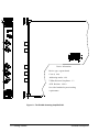
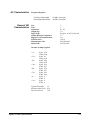
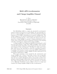
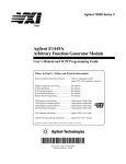
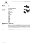
Device Information
Device type: register-based
C-size (1 slot)
Addressing modes: A16
VXIbus Revision Compliance: 1.3
SCPI Revision: 1991.0
See side of module for power/cooling
requirements
Figure 1-1. The E1446A Summing Amplifier/DAC.
1-2 Getting Started
General Description
Preparation for Use
This section shows you how to configure the module, install it in the
Agilent 75000 Series C mainframe, address the module, and download the
SCPI driver.
Note
Configuring the
Amplifier
Logical Address
The following VXIbus configuration information pertains to the
Agilent E1446A Summing Amplifier/DAC. For more (VXIbus) system
configuration information, refer to the C-Size VXIbus Systems "Installation
and Getting Started Guide" (Agilent P/N E1405-90021).
The Agilent E1446A Summing Amplifier/DAC can be configured as a
servant of the Agilent E1445A Arbitrary Function Generator or as a
stand-alone Power Amplifier/DAC.
The Agilent E1446A logical address is used as follows :
• to
place the amplifier in the servant area of a commander such as the
Agilent E1445A AFG, Agilent E1405 Command Module, or an
embedded controller.
In Agilent VXIbus systems, the servant area is defined as:
Servant area = (logical address + 1) through (logical address
+ servant area switch setting)
For example, to place the amplifier in the servant area of the
Agilent E1445A:
Agilent E1445A Logical address:
Agilent E1445A Servant Area setting:
Agilent E1446A Logical address:
80
8
88
Servant Area = (80 + 1) through (80 + 8)
• to address the Agilent E1446A (see "Addressing the Amplifier" later
in this chapter).
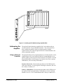
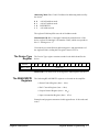
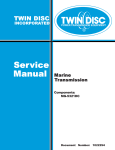
The logical address factory setting is 88. You can change the setting during
module installation. Valid addresses are from 1 to 255. The amplifier’s
logical address switch is shown in Figure 1-2.
Note
Preparation for Use
The Agilent E1446A can be set to any valid logical address (1 - 255).
However, when used with the Agilent E1445A or Agilent E1405/06, the
Getting Started 1-3
(Agilent E1446A) logical address or the (Agilent E1445A/E1405/06)
servant area must be set such that the Agilent E1446A is in the servant area
of its intended commander.
Figure 1-2. Setting the E1446A Logical Address.
Installing the
Amplifier
1-4 Getting Started
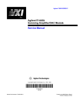
The Agilent E1446A Amplifier/DAC can be installed in any mainframe slot,
except slot 0. If the Agilent E1445A AFG is a part of your system, it is
recommended that the Amplifier/DAC be installed in a slot adjacent to the
AFG. Figure 1-3 shows how to install the module in the Agilent E1400
Series C mainframe.
Preparation for Use
Figure 1-3. Installing the E1446A Summing Amplifier/DAC.
Addressing the
Amplifier
The Agilent E1446A Summing Amplifier/DAC can be addressed by an
external controller or by an embedded controller. This section describes
how to address the amplifier using an external controller with the
Agilent E1445A AFG, with the Agilent E1405/06 Command Module, and
with an embedded controller.
Using an External
Controller
The Agilent E1446A can be programmed from an external controller via the
Agilent E1445A AFG or the Agilent E1405/06 Command Module. In an
Agilent VXIbus system using an external controller, the amplifier is located
by an (GPIB) address which consists of an interface select code, a primary
GPIB address, and a secondary GPIB address:
Interface Select Code: Determined by the address of the GPIB interface
card in the controller. For most Agilent Technologies controllers, this card
has a factory set address of 7.
Primary GPIB Address: Determined by the address of the GPIB port on
the Agilent E1405 Command Module. Valid addresses for the Command
Module are 0 to 30. The Command Module has a factory set address of 9.
Preparation for Use
Getting Started 1-5
Secondary GPIB Address : Determined by dividing the logical address of
the device by 8. If the amplifier is used with the Agilent E1445A, the
secondary address is the E1445A logical address/8. If the amplifier is used
with the Agilent E1405/06 Command Module, the secondary address is the
E1446A logical address/8.
Agilent E1445A AFG
An example of the GPIB address in an BASIC statement when the amplifier
is a servant of the Agilent E1445A is:
OUTPUT 70910;"SOUR2:VOLT:OFFS 3"
Where:
Interface Select Code = 7
(Command Module) Primary GPIB Address = 09
Secondary GPIB address (Agilent E1445A logical address/8) = 10
Agilent E1405/06 Command Module
An example of the GPIB address in an BASIC statement when the amplifier
is a servant of the Agilent E1405/06 is:
OUTPUT 70911;"SOUR:VOLT:OFFS 3"
Where:
Interface Select Code = 7
(Command Module) Primary GPIB Address = 09
Secondary GPIB address (Agilent E1446A logical address/8) = 11
Refer to Chapter 2, "Programming the Agilent E1446A", for more detailed
information.
1-6 Getting Started
Preparation for Use
Using an Embedded
Controller
The Agilent E1446A Summing Amplifier/DAC can be programmed across
the VXIbus backplane (select code 16) from an embedded controller, such
as the Agilent E1480A V/360. With this configuration, communication with
the register-based amplifier module can be accomplished via four paths:
1. Embedded controller across the VXIbus backplane to the
Agilent E1445A AFG (SCPI programming only).
2. Embedded controller to the Agilent E1405/06 Command Module via
the GPIB interface (SCPI or register-based).
3. Embedded controller to the Agilent E1405/06 over the GPIB and via
the Agilent E1445A (SCPI only).
4. Embedded controller across the VXIbus backplane to the
Agilent E1446A (register-based programming only).
Examples of how the amplifier is addressed in paths 1 through 3 are given
below. Refer to Appendix C for information on addressing the amplifier
during register-based programming.
1. OUTPUT 1680;"INP:IMP 75"
In this addressing configuration, the E1445A must be in the servant area of
the embedded controller, and the E1446A must be in the servant area of the
E1445A. Select code 16 is the only select code that can be used with this
configuration.
2. OUTPUT 70911;"INP:IMP 75"
In this addressing configuration, the E1446 must be in the servant area of
the E1405/06. Select code 7 (GPIB) is the only select code that can be used
with this configuration.
3. OUTPUT 70910;"INP:IMP 75"
In this configuration, the E1445 must be in the servant area of the E1405/06.
The E1446 must be in the servant area of the E1445A. Select code 7 (GPIB)
is the only select code that can be used with this configuration.
Downloading the
Agilent E1446A
SCPI Driver
Preparation for Use
When using the Agilent E1445A AFG, the SCPI driver is resident in ROM
and ready to control the Agilent E1446A. However, to use the Agilent
E1405 Command Module, the SCPI driver must be downloaded into the
Command Module’s non-volatile memory from a disk. Both DOS and LIF
formatted driver disks are shipped with the Agilent E1446A. The drivers
can be downloaded from controllers running DOS, BASIC (workstation),
Getting Started 1-7
IBASIC, or BASIC/UX. Downloadable driver capability is available on the
Agilent E1406 and on the E1405 with firmware revision A.06.00 or later.
To verify the firmware revision of the Command Module, you can use the
*IDN? Command:
10
20
30
40
50
DIM A$[40]
OUTPUT 70900;"*IDN?"
ENTER 70900;A$
PRINT A$
END
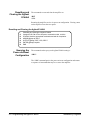
*IDN? returns identification information for the Agilent E1405 Command
Module. The result of this command is:
HEWLETT-PACKARD,E1405B,0,A.06.00
Note
For information on how to download the SCPI driver, refer to the
"Downloading Device Drivers Installation Note" (Agilent P/N
E1400-90021), or the "Agilent E1405B Command Module User’s Manual"
(Agilent P/N E1405-90004).
Basic Operation
This section provides a block diagram and description of the basic operation
of the Agilent E1446A Summing Amplifier/DAC. The description is
divided into three parts:
• Input
• Output
• Offset DAC
Additionally, the Output section is subdivided into two parts:
• Main Output
• Differential (small signal) Output.
Refer to Appendix A, "Agilent E1446A Specifications", for operating
specifications.
1-8 Getting Started
Basic Operation
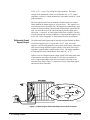
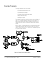
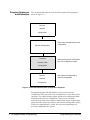
Figure 1-4. E1446A Summing Amplifier/DAC Block Diagram.
Amplifier Block
Diagram
Input
Output
Figure 1-4 shows a block diagram of the Agilent E1446A Summing
Amplifier/DAC.
The Agilent E1446A Summing Amplifier/DAC has two input channels that
have identical input amplifiers with independently controlled input
impedance and input attenuation. The input amplifier attenuators provide
independent level control prior to the summing node. The attenuation can
range from 0 to 31 dB in 1 dB steps. The input impedance can be set to
50Ω, 75Ω, or 1 MΩ.
The output channels provide the amplifier with the capability to boost the
power output of a low-power signal source, and to provide low-level
differential output. The output channels are:
• single-ended main output or power amplifier.
• differential (small signal) output; one inverting, one non-inverting.
Main Output
Basic Operation
The power amplifier sums the two input channels plus the output of a 16-bit
offset Digital-to-Analog Converter (DAC) to obtain output levels of ±10
Vpeak into a 50Ω or 75Ω load on the single-ended output or ±20 Vpeak
into high impedance. The voltage gain of the power amplifier is set at 10
(20 dB) into a matched load, and at 20 (about 26 dB) into a high impedance.
To obtain the desired output, the output attenuation and the output
impedance can be independently selected. The output impedance can be set
Getting Started 1-9
to 50Ω or 75Ω, or to 0Ω for driving into high impedance. The output
voltage can be attenuated by either 0 or 20 dB when 50Ω or 75Ω output
impedance is selected. Output attenuation is unavailable with the 0Ω mode
(high impedance).
The main output terminal may be enabled or disabled under user control.
When disabled, the output appears as an open circuit. This output is also
overload protected via an output relay. The output relay automatically opens
when an overload condition is detected and disconnects the output from the
load. An overload occurs if the sum of the inputs, plus the output of the
offset DAC, is excessive, or if the output current limit is reached. The relay
remains open until the overload condition is corrected and the output is reset
by the user. Refer to Appendix A of this manual for these specifications.
Differential (Small
Signal) Output
The differential (small signal) output sums the two input channels to obtain
a maximum output level of ±1 Vpeak into a 50/75Ω load. One of the
outputs is a non-inverting amplifier (same polarity as the input); whereas the
other is an inverting amplifier (opposite polarity as the input). Into a high
impedance, each input has a maximum gain of two. The output impedance
of each amplifier can be independently set to either 50Ω or 75Ω.
With two low level output terminals, output signals can be taken from either
of the terminals with respect to ground, or across the two terminals (in
series). Output signals taken across the two terminals will result in two
times the input voltage. Figure 1-5 shows the circuitry of the output signal
taken across the two terminals.
Figure 1-5. Measuring the Differential Output across both Terminals.
1-10 Getting Started
Basic Operation
Offset DAC
Basic Operation
A precision (DAC) allows the Agilent E1446A to provide DC offset
voltage levels. The DAC input is a complementary offset binary code. The
full scale output provides approximately ±10V into 50Ω or 75Ω load, or
approximately ±20V into high impedance.
Getting Started 1-11
1-12 Getting Started
Basic Operation
Chapter 2
Programming the Agilent E1446A
Chapter Contents
This chapter shows you how to program the Agilent E1446A using SCPI
Commands. The programming examples found in the chapter are
written in BASIC. The main sections of the chapter are:
•
•
•
•
•
•
•
•
Instrument and Programming Languages . . . . . . . . . . . .
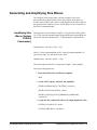
Introductory Programs . . . . . . . . . . . . . . . . . . . . . . . . . . . . .
Example Programs . . . . . . . . . . . . . . . . . . . . . . . . . . . . . . . .
Generating and Amplifying Sine Waves . . . . . . . . . . . . . .
Setting the Input Impedance. . . . . . . . . . . . . . . . . . . . . . . .
Setting DC Voltage Offsets. . . . . . . . . . . . . . . . . . . . . . . . .
Using the Differential (small signal) Outputs. . . . . . . . . .
Summing Two Signals. . . . . . . . . . . . . . . . . . . . . . . . . . . . . .
2-1
2-5
2-8
2-9
2-14
2-20
2-26
2-31
Instrument and Programming Languages
Though the E1446A amplifier is a register-based device, this module can
be programmed with SCPI commands using the Agilent E1445A AFG
or Agilent E1405 Command Module. This section describes the SCPI
programming environment.
SCPI Programming
SCPI (Standard Commands for Programmable Instruments) is an
ASCII-based instrument command language designed for test and
measurement instruments. The Agilent E1445A AFG or the Agilent
E1405 Command Module (with the amplifier driver installed) interprets
the ASCII command strings and sets the amplifier accordingly. The
AFG and Command Module do this by writing to the amplifier registers.
SCPI Command
Structure
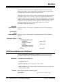
The Agilent E1446A SCPI command set is found in Chapter 3. SCPI
commands are based on a hierarchical structure, also known as a tree
system. In this system, associated commands are grouped together under
a common node or root, thus, forming subtrees or subsystems. An
example is the amplifier’s ’OUTPut2’ subsystem shown on the following
page:
Instrument and Programming Languages
Programming the Agilent E1446A 2-1
OUTPut2
:ATTenuation <attenuation>
:IMPedance <impedance>
:OVERload?
[:STATe] <mode>
:ACTual?
[query only]
[query only]
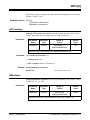
OUTPut2 is the root keyword of the command, :ATTenuation, :IMPedance,
:OVERload?, and [:STATe] are second level keywords, and :ACTual? is the
third level keyword. A colon (:) always separates a command keyword from
a lower level keyword as shown below:
OUTP2:STAT:ACT?
A semicolon (;) is used to separate two or more commands within the same
subsystem, and can also save typing. For example, sending this command
message:
OUTP2:IMP 50;OUTP2:ATT 6;OUTP2:STAT ON
is the same as sending these three commands:
OUTP2:IMP 50
OUTP2:ATT 6
OUTP2:STAT ON
A semicolon (;) and a colon (:) are used to separate two or more commands
from different subsystems in the same command message. For example:
INP1:IMP 50;:OUTP2:IMP 50
Command Coupling
The following amplifier commands are value coupled:
E1446 with E1405/06
OUTPut1:ATTenuation <attenuation>
OUTPut1:IMPedance <impedance>
SOURce:VOLTage[:LEVel][:IMMediate]:OFFSet <voltage>
E1446 with E1445
OUTPut2:ATTenuation <attenuation>
OUTPut2:IMPedance <impedance>
SOURce2:VOLTage[:LEVel][:IMMediate]:OFFSet <voltage>
This means that sending one of these commands can change the value set
previously by another one of these commands. Often, this results in
“Settings Conflict” errors when the program executes. To prevent these
errors these commands must be executed in a "coupling group".
2-2 Programming the Agilent E1446A
Instrument and Programming Languages
Executing Coupled
Commands
The list below identifies rules to follow when executing coupled commands:
• Coupled commands must be contiguous and executed in the same
program statement. This done by placing the commands in the same
program line, or by suppressing the end-of-line terminator until the
last coupled command has been sent.
To send multiple commands in a single line or in a single statement,
the commands are linked (as described previously) with a semicolon
(;) and a colon(:). For example:
OUTP2:IMP 50;OUTP2:ATT 6
or
OUTP2:IMP 50;
:OUTP2:ATT 6
In BASIC programs, the end-of-line (EOL) terminator is suppressed
by placing a semicolon (;) following the quotation mark (") which
closes the command string. For example:
OUTPUT 70910;"OUTP2:IMP 50;";
OUTPUT 70910;":OUTP2:ATT 6"
OUTPUT 70910;"OUTP2:STAT ON"
As shown, the first two lines are coupled together. The third line is
not a coupled command, therefore, the EOL terminator is not
suppressed on the second line.
• Commands not in the coupling group must either preceed or follow
commands in the coupling group.
• Un-coupled commands executed in a coupling group break the
coupling.
• Error checking occurs at the end of the coupling group.
• Hardware updates occur at the end of the coupling group.
Instrument and Programming Languages
Programming the Agilent E1446A 2-3
Instrument Driver
and Example
Programs Disks
The E1446A instrument driver and the example programs contained in this
manual are located on the following disks:
• Agilent E1446A Instrument Driver and BASIC Example
Programs - 3.5" 720 kbyte disk LIF Format (E1446-10031)
• Agilent E1446A Instrument Driver and BASIC Example
Programs - 3.5" 1.44 Mbyte disk DOS Format (E1446-10032)
The example programs are SCPI programs written in BASIC. On the LIF
formatted disk (E1446-10031), the programs are in LOAD / STORE
(PROG) format. On the DOS formatted disk (E1446-10032), the programs
are in GET / SAVE (ASCII) format.
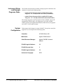
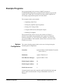
System
Configuration
Each program in this chapter is written in BASIC. Except where noted, the
programs were developed on the following system:
Controller:
HP 9000 Series 300
Mainframe:
Agilent 75000 Series C
Slot 0/Resource Manager:
Agilent E1405B Command
Module
E1445A Logical Address:
80
E1445A Servant Area:
8
E1446A Logical Address:
88
Instrument Language:
SCPI
2-4 Programming the Agilent E1446A
Instrument and Programming Languages
Introductory Programs
The introductory programs in this section include:
• Executing the Agilent E1446A self-test.
• Resetting the Agilent E1446A and clearing the Error Queue.
• Querying the Agilent E1446A power-on/reset settings.
The introductory program examples in this section were written with the
Agilent E1405 Command Module as the commander of the Agilent E1446A
Summing Amplifier/DAC.
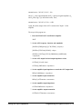
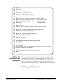
Executing the
Self-Test
The amplifier self-test is executed with the command:
*TST?
During the self-test, communication between the command module and the
on-card registers is tested. The *TST? returns one of the self-test codes
listed below:
• 0 = passed.
• 1 = failed. (An error message describes the failure.)
Executing the Self-Test
1
10
20
30
40
50
!Agilent E1446A Self-test
!Send the self-test command, enter and display the result.
OUTPUT 70911;"*TST?"
ENTER 70911;Rslt
PRINT Rslt
END
Introductory Programs
Programming the Agilent E1446A 2-5
Resetting and
Clearing the Agilent
E1446A
The commands to reset and clear the amplifier are:
*RST
*CLS
Resetting the amplifier sets it to its power-on configuration. Clearing status
on the amplifier clears the error queue.
Resetting and Clearing the Agilent E1446A
1
10
20
30
40
50
60
!Resetting and clearing the Agilent E1446A
!Assign an I/O Path for the computer, command module, and the
!E1446A. Send the appropriate commands and wait for completion.
ASSIGN @Amp to 70911
OUTPUT @Amp;"*RST;*CLS;*OPC?"
ENTER @Amp;Complete
END
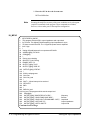
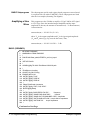
Querying the
Power-on/Reset
Configuration
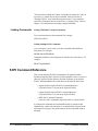
The command used to query each Agilent E1446A setting is:
*LRN?
The *LRN? command queries the power-on/reset configuration and returns
a sequence of commands that may be re-sent to the amplifier.
2-6 Programming the Agilent E1446A
Introductory Programs
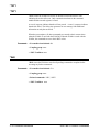
LRN
1 !RE-STORE "LRN"
10 !Assign an I/O path between the computer and the amplifier.
20 ASSIGN @Amp TO 70911
30 !Call the subprogram
40 Lrn_conf(@Amp)
50 END
60 !
70 SUB Lrn_conf(@Amp)
80 Lrn_conf: !subprogram which queries the amp reset configuration
90
DIM Lrn$[1000]
100 OUTPUT @Amp;"*LRN?"
110 ENTER @Amp;Lrn$
120 Lrn$=Lrn$&";"
130 REPEAT
140
I=POS(Lrn$,";")
150
PRINT Lrn$[1;I-1]
160
Lrn$=Lrn$[I+1]
170 UNTIL Lrn$=""
180 SUBEND
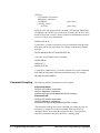
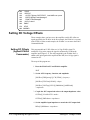
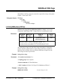
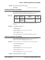
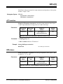
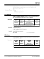
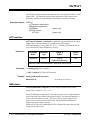
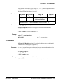
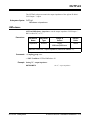
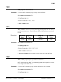
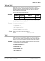
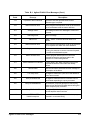
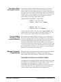
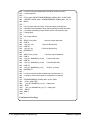
Table 2-1. E1446A Power-On/Reset Configuration (as returned by *LRN?).
Parameter
Command
Agilent E1446A
Agilent E1445A
Power-on/Reset
Settings
Input1 Attenuation
INP1:ATT
INP1:ATT
+0.00000000E+000
0 dB
Input1 Impedance
INP1:IMP
INP1:IMP
+5.00000000E+001
50Ω
Input2 Attenuation
INP2:ATT
INP2:ATT
+0.00000000E+0000 0 dB
Input2 Impedance
INP2:IMP
INP2:IMP
+5.00000000E+001
50Ω
Main Output Attenuation
OUTP1:ATT
OUTP2:ATT
+0.00000000E+000
0 dB
Main Output Impedance
OUTP1:IMP
OUTP2:IMP
+5.00000000E+001
50Ω
Main Output State
OUTP1:STAT
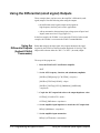
OUTP2:STAT
1
(on)
Diff "+" Impedance
OUTP2:IMP
OUTP3:IMP
+5.00000000E+001
50Ω
Diff "-" Impedance
OUTP3:IMP
OUTP4:IMP
+5.00000000E+001
50Ω
SOUR:VOLT:LEV:IMM:OFFS SOUR2:VOLT:LEV:IMM:OFFS +0.00000000E+000
0V
DC offset
Introductory Programs
Programming the Agilent E1446A 2-7
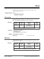
Example Programs
The example programs in this section include:
• Generating and amplifying sine waves
• Selecting the input impedance
• Using the differential (small signal) outputs
• Setting a DC offset voltage
• Summing two signals
These programs configure the amplifier according to the block diagram of
Figure 2-1. The program descriptions will often refer to this figure. The
programs were written with the amplifier configured as a servant of the
Agilent E1445A AFG, and as a servant of the Agilent E1405 Command
Module.
Refer to Chapter 3, "Command Reference" for a detailed description of the
Agilent E1446A commands. Refer to Chapter 8 of the "Agilent E1445A
Arbitrary Function Generators User’s Manual" for a detailed description of
the Agilent E1445A commands.
Figure 2-6. E1446A Functional Block Diagram.
2-8 Programming the Agilent E1446A
Example Programs
Generating and Amplifying Sine Waves
The examples in this section show you how to amplify a sine wave
generated by the Agilent E1445A. In the first program, the E1446A is a
servant of the E1445A AFG. In the second program, the E1446A amplifies
the signal from the E1445A, however; the E1446A is in the servant area of
the E1405 Command Module.
Amplifying Sine
Waves (Agilent
E1445A
Commander)
This program uses the E1446A to amplify a 2 Vpp E1445A AFG signal to
14.15 Vpp. Since the intended output amplitude and the input amplitude are
known, the amount of attenuation (0 - 31 dB attenuator) is determined as:
attenuation(dB) = 20 LOG (Vo/(Vi * 10))
where Vo is the output amplitude and Vi is the input signal amplitude (Vo
and Vi units (Vpp, Vp) must be the same). Thus,
attenuation(dB) = 20 LOG (14/20) = -3 dB
The (main) output of the AFG is connected to ’Input 1’ of the amplifier.
The steps of this program are:
1. Reset the E1445A AFG and E1446A amplifier.
*RST
2. Set the AFG frequency, function, and amplitude.
[SOURce:]FREQuency[1][:CW|:FIXed] <frequency>
[SOURce:]FUNCtion[:SHAPe] <shape>
[SOURce:]VOLTage[:LEVel][:IMMediate][:AMPLitude]
<amplitude>
3. Couple the AFG output load value to the output impedance value.
OUTPut[1]:LOAD:AUTO <mode>
OUTPut[1]:IMPedance <impedance>
Generating and Amplifying Sine Waves
Programming the Agilent E1446A 2-9
4. Set the amplifier input impedance to match the AFG output load.
INPut[1]:IMPedance <impedance>
5. Set the amplifier input attenuation.
INPut[1]:ATTenuation <attenuation>
6. Set the amplifier output impedance.
OUTPut2:IMPedance <impedance>
7. Set the amplifier output attenuation.
OUTPut2:ATTenuation <attenuation>
8. Place the AFG in the wait-for-arm state.
INITiate:IMMediate
Note
Resetting the amplifier sets many of the same conditions set by subsequent
(amplifier) commands in the program. These commands are included,
however, to show other parts of the amplifier configuration.
Note
For more information on how to program the Agilent E1445A AFG, refer to
the Agilent E1445A Arbritrary Function Generator User’s Manual.
AMPL45
1
2
3
4
10
20
30
40
50
60
70
80
!RE-STORE"AMPL45"
!The following program uses the E1445A to generate a 1 kHz, 2Vpp
!sine wave. The Agilent E1446A amplifies the signal to approximately 14 Vpp.
!
!Assign I/O path between the computer and E1445A. As the commander of
!the Agilent E1446A, the E1445A sends the amplifier its commands.
ASSIGN @Afg TO 70910
COM @Afg
!
!Set up error checking
ON INTR 7 CALL Errmsg
ENABLE INTR 7;2
Continued on Next Page
2-10 Programming the Agilent E1446A
Generating and Amplifying Sine Waves
90 OUTPUT @Afg;"*CLS"
100 OUTPUT @Afg;"*SRE 32"
110 OUTPUT @Afg;"*ESE 60"
120 !
130 !Call the subprograms
140 Rst
150 Sine_wave
160 !
170 WAIT .1 !allow interrupt to be serviced
180 OFF INTR 7
190 END
200 !
210 SUB Sine_wave
220 Sine_wave: !Subprogram which sets the E1445A to output a sine wave
230 COM @Afg
240 OUTPUT @Afg;"SOUR:FREQ1:FIX 1E3;";
!frequency
250 OUTPUT @Afg;":SOUR:FUNC:SHAP SIN;";
!function
260 OUTPUT @Afg;":SOUR:VOLT:LEV:IMM:AMPL 2VPP;"; !amplitude
270 OUTPUT @Afg;":OUTP:LOAD:AUTO ON;";
!couple load to impedance
280 OUTPUT @Afg;":OUTP:IMP 50"
!output impedance
290 !
300 !Set up the Agilent E1446A
310 OUTPUT @Afg;"INP1:IMP 50"
!input impedance
320 OUTPUT @Afg;"INP1:ATT 3"
!input attenuation (dB)
330 OUTPUT @Afg;"OUTP2:IMP 50;";
!main output impedance
340 OUTPUT @Afg;":OUTP2:ATT 0"
!main output attenuation
350 !
360 OUTPUT @Afg;"INIT:IMM"
!E1445A wait-for-arm state
370 SUBEND
380 !
390 SUB Rst
400 Rst: !Subprogram which resets the E1445A and E1446A
410 COM @Afg
420 OUTPUT @Afg;"*RST;*OPC?" !reset the AFG
430 ENTER @Afg;Complete
440 SUBEND
450 !
460 SUB Errmsg
470 Errmsg: !Subprogram which displays E1445/E1446 programming errors
480 COM @Afg
490 DIM Message$[256]
500 !Read AFG status byte register and clear service request bit
510 B=SPOLL(@Afg)
520 !End of statement if error occurs among coupled commands
530 OUTPUT @Afg;""
540 OUTPUT @Afg;"ABORT" !abort output waveform
Continued on Next Page
Generating and Amplifying Sine Waves
Programming the Agilent E1446A 2-11
550 REPEAT
560
OUTPUT @Afg;"SYST:ERR?" !read AFG error queue
570
ENTER @Afg;Code,Message$
580
PRINT Code,Message$
590 UNTIL Code=0
600 STOP
610 SUBEND
Amplifying Sine
Waves (Agilent
E1405 Commander)
This program uses the same commands and sequence as previously
described, except for the OUTPut[1] commands shown below:
6. Set the amplifieroutput impedance.
OUTPut[1]:IMPedance <impedance>
7. Set the amplifier output attenuation.
OUTPut[1]:ATTenuation <attenuation>
In this example, the E1446A is a servant to the E1405. As such, commands
sent to the amplifier (at secondary GPIB address 11) are parsed by the
Command Module rather than by the E1445A.
AMPL05
1 !RE-STORE"AMPL05"
2 !The following program uses the Agilent E1445A to generate a 1 kHz, 2Vpp
3 !sine wave. The Agilent E1446A amplifies the signal to approximately 14 Vpp.
4 !
10 !Assign I/O paths between the computer and E1445A, and between the
20 !computer and E1405. As the commander of the E1446A, the E1405 sends the
30 !amplifier its commands.
40 ASSIGN @Afg TO 70910
50 ASSIGN @Amp TO 70911
60 COM @Afg,@Amp
70 !
80 !Set up error checking
90 ON INTR 7 CALL Errmsg
100 ENABLE INTR 7;2
110 OUTPUT @Afg;"*CLS"
120 OUTPUT @Afg;"*SRE 32"
130 OUTPUT @Afg;"*ESE 60"
140 !
Continued on Next Page
2-12 Programming the Agilent E1446A
Generating and Amplifying Sine Waves
150 OUTPUT @Amp;"*CLS"
160 OUTPUT @Amp;"*SRE 32"
170 OUTPUT @Amp;"*ESE 60"
180 !
190 !Call the subprograms
200 Rst
210 Sine_wave
220 !
230 WAIT .1 !allow interrupt to be serviced
240 OFF INTR 7
250 END
260 !
270 SUB Sine_wave
280 Sine_wave: !Subprogram which sets the E1445A to output a sine wave
290 COM @Afg,@Amp
300 OUTPUT @Afg;"SOUR:FREQ1:FIX 1E3;";
!frequency
310 OUTPUT @Afg;":SOUR:FUNC:SHAP SIN;";
!function
320 OUTPUT @Afg;":SOUR:VOLT:LEV:IMM:AMPL 2VPP;"; !amplitude
330 OUTPUT @Afg;":OUTP:LOAD:AUTO ON;";
!couple load to impedance
340 OUTPUT @Afg;":OUTP:IMP 50"
!output impedance
350 !
360 !Set up the Agilent E1446A
370 OUTPUT @Amp;"INP1:IMP 50"
!input impedance
380 OUTPUT @Amp;"INP1:ATT 3"
!input attenuation (dB)
390 OUTPUT @Amp;"OUTP1:IMP 50;";
!main output impedance
400 OUTPUT @Amp;":OUTP1:ATT 0"
!main output attenuation
410 !
420 OUTPUT @Afg;"INIT:IMM"
!E1445A wait-for-arm state
430 SUBEND
440 !
450 SUB Rst
460 Rst: !Subprogram which resets the E1445A and E1446A
470 COM @Afg,@Amp
480 OUTPUT @Afg;"*RST;*OPC?" !reset the AFG
490 ENTER @Afg;Complete
500 OUTPUT @Amp;"*RST;*OPC?" !reset the AMP
510 ENTER @Amp;Complete
520 SUBEND
530 !
540 SUB Errmsg
550 Errmsg: !Subprogram which displays E1445/E1446 programming errors
560 COM @Afg,@Amp
570 DIM Message$[256]
580 !Read AFG (at sec addr 10) status byte register, clear service
590 !request bit
600 B=SPOLL(@Afg)
Continued on Next Page
Generating and Amplifying Sine Waves
Programming the Agilent E1446A 2-13
610 IF BIT(B,6) THEN !AFG requested service
620 !End of statement if error occurs among coupled commands
630
OUTPUT @Afg;""
640
OUTPUT @Afg;"ABORT" !abort output waveform
650
PRINT "E1445A errors"
660
PRINT
670
REPEAT
680
OUTPUT @Afg;"SYST:ERR?" !read AFG error queue
690
ENTER @Afg;Code,Message$
700
PRINT Code,Message$
710
UNTIL Code=0
720
STOP
730 END IF
740 !
750 !Read AMP (at sec addr 11) status byte register, clear service
760 !request bit
770 B=SPOLL(@Amp)
780 IF BIT(B,6) THEN !amplifier requested service
790 !End of statement if error occurs among coupled commands
800
OUTPUT @Amp;""
810
PRINT "E1446A errors"
820
PRINT
830
REPEAT
840
OUTPUT @Amp;"SYST:ERR?"!read AMP error queue
850
ENTER @Amp;Code,Message$
860
PRINT Code,Message$
870
UNTIL Code=0
880 END IF
890 STOP
900 SUBEND
Setting the Input Impedance
The examples in this section show you how to amplify a sine wave
generated by the Agilent E1445A. In the first program, the E1446A is a
servant of the E1445A AFG. In the second program, the E1446A amplifies
the signal from the E1445A, however; the E1446A is in the servant area of
the E1405 Command Module.
Setting the Input
Impedance
(Agilent E1445A
Commander)
This program sets the E1446A’s input impedance to match the output
impedance of the E1445A. The signal supplied by the E1445A is a 1 Vpp, 2
MHz square wave. The signal is amplified to 6.3 Vpp. Again, when the
intended output amplitude and the input amplitude are known, the amount of
attenuation (0 - 31 dB attenuator) is determined by:
2-14 Programming the Agilent E1446A
Setting the Input Impedance
attenuation(dB) = 20 LOG (Vo/(Vi * 10))
where Vo is the output amplitude and Vi is the input signal amplitude (Vo
and Vi units (Vpp, Vp) must be the same). Thus,
attenuation(dB) = 20 LOG (6.3/10) = -4 dB
Again, the (main) output of the AFG is connected to ’Input 1’ of the
amplifier.
The steps of this program are:
1. Reset the E1445A AFG and E1446A amplifier.
*RST
2. Set the AFG frequency, function, and amplitude.
[SOURce:]FREQuency[1][:CW|:FIXed] <frequency>
[SOURce:]FUNCtion[:SHAPe] <shape>
[SOURce:]VOLTage[:LEVel][:IMMediate][:AMPLitude]
<amplitude>
3. Set the AFG output load and output impedance values.
OUTPut[1]:LOAD <load>
OUTPut[1]:IMPedance <impedance>
4. Set the amplifier input impedance to match the AFG output load.
INPut[1]:IMPedance <impedance>
5. Set the amplifier input attenuation.
INPut[1]:ATTenuation <attenuation>
6. Set the amplifier output impedance.
OUTPut2:IMPedance <impedance>
7. Set the amplifier output attenuation.
OUTPut2:ATTenuation <attenuation>
Setting the Input Impedance
Programming the Agilent E1446A 2-15
8. Place the AFG in the wait-for-arm state.
INITiate:IMMediate
Note
Resetting the amplifier sets many of the same conditions set by subsequent
(amplifier) commands in the program. These commands are included,
however, to show other parts of the amplifier configuration.
IN_IMP45
1 !RE-STORE"IN_IMP45"
2 !This program sets the AFG’s output impedance and output load
3 !to 75 ohms. The Agilent E1446A amplifier’s input impedance is set to
4 !75 ohms to match the AFG. The 1 Vpp AFG square wave is amplified
5 !to 6.3 Vpp.
6 !
10 !Assign I/O path between the computer and E1445A.
20 ASSIGN @Afg TO 70910
30 COM @Afg
40 !
50 !Set up error checking
60 ON INTR 7 CALL Errmsg
70 ENABLE INTR 7;2
80 OUTPUT @Afg;"*CLS"
90 OUTPUT @Afg;"*SRE 32"
100 OUTPUT @Afg;"*ESE 60"
110 !
120 !Call the subprograms
130 CALL Rst
140 CALL Out_load
150 !
160 WAIT .1 !allow interrupt to be serviced
170 OFF INTR 7
180 END
190 !
200 SUB Out_load
210 Out_load: !Subprogram which sets the output load
220 COM @Afg
230 OUTPUT @Afg;"SOUR:FREQ1:FIX 2E6;";
!frequency
240 OUTPUT @Afg;":SOUR:FUNC:SHAP SQU;";
!function
250 OUTPUT @Afg;":SOUR:VOLT:LEV:IMM:AMPL 1VPP;"; !amplitude
260 OUTPUT @Afg;":OUTP:IMP 75;";
!output impedance
270 OUTPUT @Afg;":OUTP:LOAD 75"
!output load
Continued on Next Page
2-16 Programming the Agilent E1446A
Setting the Input Impedance
280 !
290 !Set up amplifier
300 OUTPUT @Afg;"INP1:IMP 75"
!input impedance
310 OUTPUT @Afg;"INP1:ATT 4"
!input attenuation (dB)
320 OUTPUT @Afg;"OUTP2:IMP 50"
!main output impedance
330 OUTPUT @Afg;"OUTP2:ATT 0"
!main output attenuation (dB)
340 !
350 OUTPUT @Afg;"INIT:IMM"
!E1445A wait-for-arm state
360 SUBEND
370 !
380 SUB Rst
390 Rst: !Subprogram which resets the E1445 and E1446
400 COM @Afg
410 OUTPUT @Afg;"*RST;*OPC?"
!reset the AFG
420 ENTER @Afg;Complete
430 SUBEND
440 !
450 SUB Errmsg
460 Errmsg: !Subprogram which displays E1445/E1446 programming errors
470 COM @Afg
480 DIM Message$[256]
490 !Read AFG status byte register and clear service request bit
500 B=SPOLL(@Afg)
510 !End of statement if error occurs among coupled commands
520 OUTPUT @Afg;""
530 OUTPUT @Afg;"ABORT" !abort output waveform
540 REPEAT
550
OUTPUT @Afg;"SYST:ERR?" !read AFG error queue
560
ENTER @Afg;Code,Message$
570
PRINT Code,Message$
580 UNTIL Code=0
590 STOP
600 SUBEND
Setting Input
Impedance
(Agilent E1405B
Commander)
This program uses the same commands and sequence as previously
described, except for the OUTPut[1] commands shown below:
6. Set the amplifier output impedance.
OUTPut[1]:IMPedance <impedance>
7. Set the amplifier output attenuation.
OUTPut[1]:ATTenuation <attenuation>
Setting the Input Impedance
Programming the Agilent E1446A 2-17
In this example, the E1446A is a servant to the E1405. As such, commands
sent to the amplifier (at secondary GPIB address 11) are parsed by the
Command Module rather than by the E1445A.
IN_IMP05
1 !RE-STORE"IN_IMP05"
2 !This program sets the AFG’s output impedance and output load
3 !to 75 ohms. The Agilent E1446A amplifier’s input impedance is set to
4 !75 ohms to match the AFG. The 1 Vpp AFG square wave is amplified
5 !to 6.3 Vpp.
6 !
10 !Assign I/O paths between the computer and E1445A and E1405.
20 ASSIGN @Afg TO 70910
30 ASSIGN @Amp TO 70911
40 COM @Afg,@Amp
50 !
60 !Set up error checking
70 ON INTR 7 CALL Errmsg
80 ENABLE INTR 7;2
90 OUTPUT @Afg;"*CLS"
100 OUTPUT @Afg;"*SRE 32"
110 OUTPUT @Afg;"*ESE 60"
120 !
130 OUTPUT @Amp;"*CLS"
140 OUTPUT @Amp;"*SRE 32"
150 OUTPUT @Amp;"*ESE 60"
160 !
170 !Call the subprograms
180 CALL Rst
190 CALL Out_load
200 !
210 WAIT .1 !allow interrupt to be serviced
220 OFF INTR 7
230 END
240 !
250 SUB Out_load
260 Out_load: !Subprogram which sets the output load
270 COM @Afg,@Amp
280 OUTPUT @Afg;"SOUR:FREQ1:FIX 2E6;";
!frequency
290 OUTPUT @Afg;":SOUR:FUNC:SHAP SQU;";
!function
300 OUTPUT @Afg;":SOUR:VOLT:LEV:IMM:AMPL 1VPP;"; !amplitude
310 OUTPUT @Afg;":OUTP:IMP 75;";
!output impedance
320 OUTPUT @Afg;":OUTP:LOAD 75"
!output load
330 !
Continued on Next Page
2-18 Programming the Agilent E1446A
Setting the Input Impedance
340 !Set up amplifier
350 OUTPUT @Amp;"INP1:IMP 75"
!input impedance
360 OUTPUT @Amp;"INP1:ATT 4"
!input attenuation (dB)
370 OUTPUT @Amp;"OUTP1:IMP 50"
!main output impedance
380 OUTPUT @Amp;"OUTP1:ATT 0"
!main output attenuation (dB)
390 !
400 OUTPUT @Afg;"INIT:IMM"
!E1445A wait-for-arm state
410 SUBEND
420 !
430 SUB Rst
440 Rst: !Subprogram which resets the E1445 and E1446
450 COM @Afg,@Amp
460 OUTPUT @Afg;"*RST;*OPC?"
!reset the AFG
470 ENTER @Afg;Complete
480 OUTPUT @Amp;"*RST;*OPC?"
!reset the AMP
490 ENTER @Amp;Complete
500 SUBEND
510 !
520 SUB Errmsg
530 Errmsg: !Subprogram which displays E1445/E1446 programming errors
540 COM @Afg,@Amp
550 DIM Message$[256]
560 !Read AFG (at sec addr 10) status byte register, clear service
570 !request bit
580 B=SPOLL(@Afg)
590 IF BIT(B,6) THEN !AFG requested service
600 !End of statement if error occurs among coupled commands
610
OUTPUT @Afg;""
620
OUTPUT @Afg;"ABORT"!abort output waveform
630
PRINT "E1445A errors"
640
PRINT
650
REPEAT
660
OUTPUT @Afg;"SYST:ERR?" !read AFG error queue
670
ENTER @Afg;Code,Message$
680
PRINT Code,Message$
690
UNTIL Code=0
700
STOP
710 END IF
720 !
730 !Read AMP (at sec addr 11) status byte register, clear service
740 !request bit
750 B=SPOLL(@Amp)
760 IF BIT(B,6) THEN !amplifier requested service
770 !End of statement if error occurs among coupled commands
780
OUTPUT @Amp;""
790
PRINT "E1446A errors"
Continued on Next Page
Setting the Input Impedance
Programming the Agilent E1446A 2-19
800
PRINT
810
REPEAT
820
OUTPUT @Amp;"SYST:ERR?" !read AMP error queue
830
ENTER @Amp;Code,Message$
840
PRINT Code,Message$
850
UNTIL Code=0
860 END IF
870 STOP
880 SUBEND
Setting DC Voltage Offsets
These examples show you how to use the amplifier to add a DC offset to a
signal supplied by the E1445A. In the first example, the E1446A is a servant
to the E1445A. In the second example, the E1446A is a servant to the E1405
Command Module.
Setting DC Offsets
(Agilent E1445A
Commander)
This program adds an 8V DC offset to a 0.4 Vpp E1445A signal. To
maintain 0.4 Vpp at the output, the signal is attenuated by 20 dB at the
amplifier input (Figure 2-1). The offset supplied by the E1446A DAC is
added to the input signal and is amplified. Into 50W, the 0.4 Vpp signal is
centered on 8V.
The steps of this program are:
1. Reset the E1445A AFG and E1446A amplifier.
*RST
2. Set the AFG frequency, function, and amplitude.
[SOURce:]FREQuency[1][:CW|:FIXed] <frequency>
[SOURce:]FUNCtion[:SHAPe] <shape>
[SOURce:]VOLTage[:LEVel][:IMMediate][:AMPLitude]
<amplitude>
3. Couple the AFG output load value to the output impedance value.
OUTPut[1]:LOAD:AUTO <mode>
OUTPut[1]:IMPedance <impedance>
4. Set the amplifier input impedance to match the AFG output load.
INPut[1]:IMPedance <impedance>
2-20 Programming the Agilent E1446A
Setting DC Voltage Offsets
5. Set the amplifier input attenuation.
INPut[1]:ATTenuation <attenuation>
6. Set the amplifier main output impedance.
OUTPut2:IMPedance <impedance>
7. Set the amplifier main output attenuation.
OUTPut2:ATTenuation <attenuation>
8. Set the DC offset value.
SOURce2:VOLTage[:LEVel][:IMMediate]:OFFSet <offset>
9. Place the AFG in the wait-for-arm state.
INITiate:IMMediate
Note
Resetting the amplifier sets many of the same conditions set by subsequent
(amplifier) commands in the program. These commands are included,
however, to show other parts of the amplifier configuration.
OFFS45
1
2
3
4
5
6
7
8
10
20
30
40
50
!RE-STORE"OFFS45"
!This program uses the E1446A to generate an 8V DC offset for a
!0.4 Vpp signal supplied by the E1445A AFG. To accomplish this, the
!AFG signal is attenuated by 20 dB at the amplifier input. The amplifier
!offset is set to 8V, the output impedance to 50 ohms, and the output
!attenuation to 0 dB. Into 50 ohms, the 0.4 Vpp signal is centered on
!8 volts.
!
!Assign I/O path between the computer and E1445A. As the commander of
!the Agilent E1446A, the E1445A sends the amplifier its commands.
ASSIGN @Afg TO 70910
COM @Afg
!
Continued on Next Page
Setting DC Voltage Offsets
Programming the Agilent E1446A 2-21
60 !Set up error checking
70 ON INTR 7 CALL Errmsg
80 ENABLE INTR 7;2
90 OUTPUT @Afg;"*CLS"
100 OUTPUT @Afg;"*SRE 32"
110 OUTPUT @Afg;"*ESE 60"
120 !
130 !Call the subprograms
140 Rst
150 Offset
160 !
170 WAIT .1 !allow interrupt to be serviced
180 OFF INTR 7
190 END
200 !
210 SUB Offset
220 Offset: !Subprogram which sets up the E1445A and E1446A
230 COM @Afg
240 OUTPUT @Afg;"SOUR:FREQ1:FIX 1E3;";
!frequency
250 OUTPUT @Afg;":SOUR:FUNC:SHAP SIN;";
!function
260 OUTPUT @Afg;":SOUR:VOLT:LEV:IMM:AMPL .4VPP;"; !amplitude
270 OUTPUT @Afg;":OUTP:LOAD:AUTO ON;";
!couple load to impedance
280 OUTPUT @Afg;":OUTP:IMP 50"
!impedance
290 !
300 !Set up the Agilent E1446A
310 OUTPUT @Afg;"INP1:IMP 50"
!input impedance
320 OUTPUT @Afg;"INP1:ATT 20"
!input attenuation (dB)
330 OUTPUT @Afg;"OUTP2:IMP 50;";
!main output impedance
340 OUTPUT @Afg;":OUTP2:ATT 0;";
!main output attenuation (dB)
350 OUTPUT @Afg;":SOUR2:VOLT:LEV:IMM:OFFS 8" !DC offset
360 !
370 OUTPUT @Afg;"INIT:IMM"
!E1445A wait-for-arm state
380 SUBEND
390 !
400 SUB Rst
410 Rst: !Subprogram which resets the E1445A and E1446A
420 COM @Afg
430 OUTPUT @Afg;"*RST;*OPC?" !reset the AFG
440 ENTER @Afg;Complete
450 SUBEND
460 !
470 SUB Errmsg
480 Errmsg: !Subprogram which displays E1445/E1446 programming errors
490 COM @Afg
500 DIM Message$[256]
Continued on Next Page
2-22 Programming the Agilent E1446A
Setting DC Voltage Offsets
510 !Read AFG status byte register and clear service request bit
520 B=SPOLL(@Afg)
530 !End of statement if error occurs among coupled commands
540 OUTPUT @Afg;""
550 OUTPUT @Afg;"ABORT" !abort output waveform
560 REPEAT
570
OUTPUT @Afg;"SYST:ERR?" !read AFG error queue
580
ENTER @Afg;Code,Message$
590
PRINT Code,Message$
600 UNTIL Code=0
610 STOP
620 SUBEND
Setting DC Offsets
(Agilent E1405
Commander)
This program uses the same commands and sequence as previously
described, except for the OUTPut[1] and SOURCe:VOLTage commands
shown below:
6. Set the amplifier main output impedance.
OUTPut[1]:IMPedance <impedance>
7. Set the amplifier main output attenuation.
OUTPut[1]:ATTenuation <attenuation>
8. Set the DC offset value.
SOURce:VOLTage[:LEVel][:IMMediate]:OFFSet <offset>
In this example, the E1446A is a servant to the E1405. As such, commands
sent to the amplifier (at secondary GPIB address 11) are parsed by the
Command Module rather than by the E1445A.
OFFS05
1
2
3
4
5
6
7
8
10
20
30
!RE-STORE"OFFS05"
!This program uses the E1446A to generate an 8V DC offset for a
!0.4 Vpp signal supplied by the E1445A AFG. To accomplish this, the
!AFG signal is attenuated by 20 dB at the amplifier input. The amplifier
!offset is set to 8V, the output impedance to 50 ohms, and the output
!attenuation to 0 dB. Into 50 ohms, the 0.4 Vpp signal is centered on
!8 volts.
!
!Assign I/O path between the computer and E1445A and E1446A.
ASSIGN @Afg TO 70910
ASSIGN @Amp TO 70911
Continued on Next Page
Setting DC Voltage Offsets
Programming the Agilent E1446A 2-23
40 COM @Afg,@Amp
50 !
60 !Set up error checking
70 ON INTR 7 CALL Errmsg
80 ENABLE INTR 7;2
90 OUTPUT @Afg;"*CLS"
100 OUTPUT @Afg;"*SRE 32"
110 OUTPUT @Afg;"*ESE 60"
120 !
130 OUTPUT @Amp;"*CLS"
140 OUTPUT @Amp;"*SRE 32"
150 OUTPUT @Amp;"*ESE 60"
160 !
170 !Call the subprograms
180 Rst
190 Offset
200 !
210 WAIT .1 !allow interrupt to be serviced
220 OFF INTR 7
230 END
240 !
250 SUB Offset
260 Offset: !Subprogram which sets up the E1445A and E1446A
270 COM @Afg,@Amp
280 OUTPUT @Afg;"SOUR:FREQ1:FIX 1E3;";
!frequency
290 OUTPUT @Afg;":SOUR:FUNC:SHAP SIN;";
!function
300 OUTPUT @Afg;":SOUR:VOLT:LEV:IMM:AMPL .4VPP;"; !amplitude
310 OUTPUT @Afg;":OUTP:LOAD:AUTO ON;";
!couple load to impedance
320 OUTPUT @Afg;":OUTP:IMP 50"
!impedance
330 !
340 !Set up the Agilent E1446A
350 OUTPUT @Amp;"INP1:IMP 50"
!input impedance
360 OUTPUT @Amp;"INP1:ATT 20"
!input attenuation (dB)
370 OUTPUT @Amp;"OUTP1:IMP 50;";
!main output impedance
380 OUTPUT @Amp;":OUTP1:ATT 0;";
!main output attenuation (dB)
390 OUTPUT @Amp;":SOUR:VOLT:LEV:IMM:OFFS 8" !DC offset
400 !
410 OUTPUT @Afg;"INIT:IMM"
!E1445A wait-for-arm state
420 SUBEND
430 !
440 SUB Rst
450 Rst: !Subprogram which resets the E1445A and E1446A
460 COM @Afg,@Amp
470 OUTPUT @Afg;"*RST;*OPC?" !reset the AFG
480 ENTER @Afg;Complete
490 OUTPUT @Amp;"*RST;*OPC?" !reset the AFG
Continued on Next Page
2-24 Programming the Agilent E1446A
Setting DC Voltage Offsets
500 ENTER @Amp;Complete
510 SUBEND
520 !
530 SUB Errmsg
540 Errmsg: !Subprogram which displays E1445/E1446 programming errors
550 COM @Afg,@Amp
560 DIM Message$[256]
570 !Read AFG (at sec addr 10) status byte register, clear service
580 !request bit
590 B=SPOLL(@Afg)
600 IF BIT(B,6) THEN !AFG requested service
610 !End of statement if error occurs among coupled commands
620
OUTPUT @Afg;""
630
OUTPUT @Afg;"ABORT" !abort output waveform
640
PRINT "E1445A errors"
650
PRINT
660
REPEAT
670
OUTPUT @Afg;"SYST:ERR?" !read AFG error queue
680
ENTER @Afg;Code,Message$
690
PRINT Code,Message$
700
UNTIL Code=0
710
STOP
720 END IF
730 !
740 !Read AMP (at sec addr 11) status byte register, clear service
750 !request bit
760 B=SPOLL(@Amp)
770 IF BIT(B,6) THEN !amplifier requested service
780 !End of statement if error occurs among coupled commands
790
OUTPUT @Amp;""
800
PRINT "E1446A errors"
810
PRINT
820
REPEAT
830
OUTPUT @Amp;"SYST:ERR?"!read AMP error queue
840
ENTER @Amp;Code,Message$
850
PRINT Code,Message$
860
UNTIL Code=0
870 END IF
880 STOP
890 SUBEND
Setting DC Voltage Offsets
Programming the Agilent E1446A 2-25
Using the Differential (small signal) Outputs
These examples show you how to use the amplifier’s differential (small
signal) outputs. Note the following when using the outputs:
• the differential (small signal) outputs are designed for
high-frequency and low-power source applications.
• with no attenuation, the maximum input voltage (sum of Input1 and
Input2) must not exceed 2 Vpp (Figure 2-1).
In the first example, the E1446A is a servant to the E1445A. In the second
example, the E1446A is a servant to the E1405 Command Module.
Using the
Differential Outputs
(Agilent E1445A
Commander)
Rather than amplify the input signal, this program attenuates the signal
supplied by the E1445A to obtain an output amplitude of 10 mVpp. The
output can be taken at either the ’Diff +’ or ’Diff -’ (inverted) output.
The steps of this program are:
1. Reset the E1445A AFG and E1446A amplifier.
*RST
2. Set the AFG frequency, function, and (minimum) amplitude.
[SOURce:]FREQuency[1][:CW|:FIXed] <frequency>
[SOURce:]FUNCtion[:SHAPe] <shape>
[SOURce:]VOLTage[:LEVel][:IMMediate][:AMPLitude]
<amplitude>
3. Couple the AFG output load value to the output impedance value.
OUTPut[1]:LOAD:AUTO <mode>
OUTPut[1]:IMPedance <impedance>
4. Set the amplifier input impedance to match the AFG output load.
INPut[1]:IMPedance <impedance>
5. Set the amplifier input attenuation.
INPut[1]:ATTenuation <attenuation>
2-26 Programming the Agilent E1446A
Using the Differential (small signal) Outputs
6. Set the amplifier ’Diff +’ and ’Diff -’ output impedances.
OUTPut3:IMPedance <impedance>
OUTPut4:IMPedance <impedance>
7. Place the AFG in the wait-for-arm state.
INITiate:IMMediate
Note
Resetting the amplifier sets many of the same conditions set by subsequent
(amplifier) commands in the program. These commands are included,
however, to show other parts of the amplifier configuration.
DIFF45
1 !RE-STORE"DIFF45"
2 !This program uses the E1446A to generate a 10 mVpp signal from a
3 !0.323738 Vpp signal supplied by the E1445A AFG. To accomplish this, the
4 !AFG signal is attenuated by 30 dB at the amplifier input. The output is
5 !taken from the ’Diff +’ and ’Diff - ’ outputs whose output impedances
6 !are set to 50 ohms.
7 !
10 !Assign I/O path between the computer and E1445A. As the commander of
20 !the Agilent E1446A, the E1445A sends the amplifier its commands.
30 ASSIGN @Afg TO 70910
40 COM @Afg
50 !
60 !Set up error checking
70 ON INTR 7 CALL Errmsg
80 ENABLE INTR 7;2
90 OUTPUT @Afg;"*CLS"
100 OUTPUT @Afg;"*SRE 32"
110 OUTPUT @Afg;"*ESE 60"
120 !
130 !Call the subprograms
140 Rst
150 Diffout
160 !
Continued on Next Page
Using the Differential (small signal) Outputs
Programming the Agilent E1446A 2-27
170 WAIT .1 !allow interrupt to be serviced
180 OFF INTR 7
190 END
200 !
210 SUB Diffout
220 Diffout: !Subprogram which sets up the E1445A and E1446A
230 COM @Afg
240 OUTPUT @Afg;"SOUR:FREQ1:FIX 1E3;";
!frequency
250 OUTPUT @Afg;":SOUR:FUNC:SHAP SQU;";
!function
260 OUTPUT @Afg;":SOUR:VOLT:LEV:IMM:AMPL MIN;"; !amplitude (.161869 Vpk)
270 OUTPUT @Afg;":OUTP:LOAD:AUTO ON;";
!couple load to impedance
280 OUTPUT @Afg;":OUTP:IMP 50"
!impedance
290 !
300 !Set up the Agilent E1446A
310 OUTPUT @Afg;"INP1:IMP 50"
!input impedance
320 OUTPUT @Afg;"INP1:ATT 30"
!input attenuation (dB)
330 OUTPUT @Afg;"OUTP3:IMP 50"
!Diff + output impedance
340 OUTPUT @Afg;"OUTP4:IMP 50"
!Diff - output impedance
350 !
360 OUTPUT @Afg;"INIT:IMM"
!E1445A wait-for-arm state
370 SUBEND
380 !
390 SUB Rst
400 Rst: !Subprogram which resets the E1445A and E1446A
410 COM @Afg
420 OUTPUT @Afg;"*RST;*OPC?" !reset the AFG
430 ENTER @Afg;Complete
440 SUBEND
450 !
460 SUB Errmsg
470 Errmsg: !Subprogram which displays E1445/E1446 programming errors
480 COM @Afg
490 DIM Message$[256]
500 !Read AFG status byte register and clear service request bit
510 B=SPOLL(@Afg)
520 !End of statement if error occurs among coupled commands
530 OUTPUT @Afg;""
540 OUTPUT @Afg;"ABORT" !abort output waveform
550 REPEAT
560
OUTPUT @Afg;"SYST:ERR?" !read AFG error queue
570
ENTER @Afg;Code,Message$
580
PRINT Code,Message$
590 UNTIL Code=0
600 STOP
610 SUBEND
2-28 Programming the Agilent E1446A
Using the Differential (small signal) Outputs
Using the
Differential Outputs
(Agilent E1405
Commander)
This program uses the same commands and sequence as previously
described, except for the OUTPut2 and OUTPut3 commands shown below:
6. Set the amplifier ’Diff +’ and ’Diff -’ output impedances.
OUTPut2:IMPedance <impedance>
OUTPut3:IMPedance <impedance>
In this example, the E1446A is a servant to the E1405. As such, commands
sent to the amplifier (at secondary GPIB address 11) are parsed by the
Command Module rather than by the E1445A.
DIFF05
1 !RE-STORE"DIFF05"
2 !This program uses the E1446A to generate a 10 mVpp signal from a
3 !0.323738 Vpp signal supplied by the E1445A AFG. To accomplish this, the
4 !AFG signal is attenuated by 30 dB at the amplifier input. The output is
5 !taken from the ’Diff +’ and ’Diff - ’ outputs whose output impedances
6 !are set to 50 ohms.
7 !
10 !Assign I/O path between the computer and E1445A, and E1446A.
20 ASSIGN @Afg TO 70910
30 ASSIGN @Amp TO 70911
40 COM @Afg,@Amp
50 !
60 !Set up error checking
70 ON INTR 7 CALL Errmsg
80 ENABLE INTR 7;2
90 OUTPUT @Afg;"*CLS"
100 OUTPUT @Afg;"*SRE 32"
110 OUTPUT @Afg;"*ESE 60"
120 !
130 OUTPUT @Amp;"*CLS"
140 OUTPUT @Amp;"*SRE 32"
150 OUTPUT @Amp;"*ESE 60"
160 !
170 !Call the subprograms
180 Rst
190 Diffout
200 !
210 WAIT .1 !allow interrupt to be serviced
220 OFF INTR 7
230 END
Continued on Next Page
Using the Differential (small signal) Outputs
Programming the Agilent E1446A 2-29
240 !
250 SUB Diffout
260 Diffout: !Subprogram which sets up the E1445A and E1446A
270 COM @Afg,@Amp
280 OUTPUT @Afg;"SOUR:FREQ1:FIX 1E3;";
!frequency
290 OUTPUT @Afg;":SOUR:FUNC:SHAP SIN;";
!function
300 OUTPUT @Afg;":SOUR:VOLT:LEV:IMM:AMPL MIN;"; !amplitude (.161869 Vpk)
310 OUTPUT @Afg;":OUTP:LOAD:AUTO ON;";
!couple load to impedance
320 OUTPUT @Afg;":OUTP:IMP 50"
!impedance
330 !
340 !Set up the Agilent E1446A
350 OUTPUT @Amp;"INP1:IMP 50"
!input impedance
360 OUTPUT @Amp;"INP1:ATT 30"
!input attenuation (dB)
370 OUTPUT @Amp;"OUTP2:IMP 50"
!Diff + output impedance
380 OUTPUT @Amp;"OUTP3:IMP 50"
!Diff - output impedance
390 !
400 OUTPUT @Afg;"INIT:IMM"
!E1445A wait-for-arm state
410 SUBEND
420 !
430 SUB Rst
440 Rst: !Subprogram which resets the E1445A and E1446A
450 COM @Afg,@Amp
460 OUTPUT @Afg;"*RST;*OPC?" !reset the AFG
470 ENTER @Afg;Complete
480 OUTPUT @Amp;"*RST;*OPC?" !reset the amplifier
490 ENTER @Amp;Complete
500 SUBEND
510 !
520 SUB Errmsg
530 Errmsg: !Subprogram which displays E1445/E1446 programming errors
540 COM @Afg,@Amp
550 DIM Message$[256]
560 !Read AFG (at sec addr 10) status byte register, clear service
570 !request bit
580 B=SPOLL(@Afg)
590 IF BIT(B,6) THEN !AFG requested service
600 !End of statement if error occurs among coupled commands
610
OUTPUT @Afg;""
620
OUTPUT @Afg;"ABORT"!abort output waveform
630
PRINT "E1445A errors"
640
PRINT
650
REPEAT
660
OUTPUT @Afg;"SYST:ERR?" !read AFG error queue
670
ENTER @Afg;Code,Message$
680
PRINT Code,Message$
690
UNTIL Code=0
Continued on Next Page
2-30 Programming the Agilent E1446A
Using the Differential (small signal) Outputs
700
STOP
710 END IF
720 !
730 !Read AMP (at sec addr 11) status byte register, clear service
740 !request bit
750 B=SPOLL(@Amp)
760 IF BIT(B,6) THEN !amplifier requested service
770 !End of statement if error occurs among coupled commands
780
OUTPUT @Amp;""
790
PRINT "E1446A errors"
800
PRINT
810
REPEAT
820
OUTPUT @Amp;"SYST:ERR?" !read AMP error queue
830
ENTER @Amp;Code,Message$
840
PRINT Code,Message$
850
UNTIL Code=0
860 END IF
870 STOP
880 SUBEND
Summing Two Signals
This program uses the E1446A to sum the signals from two E1445A AFGs.
The AFGs at logical addresses 80 and 88 (secondary GPIB addresses 10 and
11), generate 1 Vpp, 5 kHz and 100 kHz sine waves respectively. The signal
from the AFG at logical address 80 is applied to E1446A ’Input 1’. The
signal from the AFG at logical address 88 is applied to ’Input 2’. The
E1446A is in the servant area of the AFG at logical address 80.
The steps of the program are as follows:
1. Reset the E1445A AFGs and E1446A amplifier.
*RST
2. Set the E1445As’ reference oscillator sources to CLK10.
[SOURce:]ROSCillator:SOURce <source>
Summing Two Signals
Programming the Agilent E1446A 2-31
3. Set the AFG frequency, function, and amplitude.
[SOURce:]FREQuency[1][:CW|:FIXed] <frequency>
[SOURce:]FUNCtion[:SHAPe] <shape>
[SOURce:]VOLTage[:LEVel][:IMMediate][:AMPLitude]
<amplitude>
4. Couple the AFG output load value to the output impedance value.
OUTPut[1]:LOAD:AUTO <mode>
OUTPut[1]:IMPedance <impedance>
5. Set the amplifier input impedance to match the AFG output load.
INPut[1]:IMPedance <impedance>
INPut2:IMPedance <impedance>
6. Set the amplifier input attenuation.
INPut[1]:ATTenuation <attenuation>
INPut2:ATTenuation <attenuation>
7. Set the amplifier ’Diff +’ output impedance.
OUTPut3:IMPedance <impedance>
8. Place the AFGs in the wait-for-arm state.
INITiate:IMMediate
SUM45
1
2
3
4
5
6
7
9
10
!RE-STORE"SUM45"
!The following program uses the E1446A to sum the output signals of
!two E1445As. The E1445A at secondary address 10 (logical address 80)
!outputs a 1 Vpp, 5 kHz sine wave. The E1445A at secondary address 11
!(logical address 88) outputs a 1 Vpp, 100 kHz sine wave. To prevent
!the E1445A signals from drifting, both AFG’s use CLK10 as their
!reference oscillator source. The E1446A sums these signals, and the
!output is taken at the ’Diff +’ output.
!
Continued on Next Page
2-32 Programming the Agilent E1446A
Summing Two Signals
20 !Assign I/O paths between the computer and E1445As. The E1445A at
30 !secondary address 10 is the commander for the E1446A.
40 ASSIGN @Afg80 TO 70910
50 ASSIGN @Afg88 TO 70911
60 COM @Afg80,@Afg88
70 !
80 !Set up error checking
90 ON INTR 7 CALL Errmsg
100 ENABLE INTR 7;2
110 OUTPUT @Afg80;"*CLS"
120 OUTPUT @Afg80;"*SRE 32"
130 OUTPUT @Afg80;"*ESE 60"
140 !
150 OUTPUT @Afg88;"*CLS"
160 OUTPUT @Afg88;"*SRE 32"
170 OUTPUT @Afg88;"*ESE 60"
180 !
190 !Call the subprograms
200 Rst
210 Afg_setup
220 !
230 WAIT .1 !allow interrupt to be serviced
240 OFF INTR 7
250 END
260 !
270 SUB Afg_setup
280 Afg_setup: !Subprogram which sets up the E1445As and E1446A
290 COM @Afg80,@Afg88
300 !Set up E1445A at secondary address 10
310 OUTPUT @Afg80;"SOUR:ROSC:SOUR CLK10;";
!ref osc source
320 OUTPUT @Afg80;":SOUR:FREQ1:FIX 5E3;";
!frequency
330 OUTPUT @Afg80;":SOUR:FUNC:SHAP SIN;";
!function
340 OUTPUT @Afg80;":SOUR:VOLT:LEV:IMM:AMPL 1VPP;"; !amplitude
350 OUTPUT @Afg80;":OUTP:LOAD:AUTO ON;";
!couple load to impedance
360 OUTPUT @Afg80;":OUTP:IMP 50"
!impedance
370 !
380 !Setup E1445A at secondary address 11
390 OUTPUT @Afg88;"SOUR:ROSC:SOUR CLK10;";
!ref osc source
400 OUTPUT @Afg88;":SOUR:FREQ1:FIX 100E3;";
!frequency
410 OUTPUT @Afg88;":SOUR:FUNC:SHAP SIN;";
!function
420 OUTPUT @Afg88;":SOUR:VOLT:LEV:IMM:AMPL 1VPP;"; !amplitude
430 OUTPUT @Afg88;":OUTP:LOAD:AUTO ON;";
!couple load to impedance
440 OUTPUT @Afg88;":OUTP:IMP 50"
!impedance
450 !
Continued on Next Page
Summing Two Signals
Programming the Agilent E1446A 2-33
460 !Set up the Agilent E1446A
470 OUTPUT @Afg80;"INP1:IMP 50"
!input 1 impedance
480 OUTPUT @Afg80;"INP1:ATT 0"
!input 1 attenuation (dB)
490 OUTPUT @Afg80;"INP2:IMP 50"
!input 2 impedance
500 OUTPUT @Afg80;"INP2:ATT 0"
!input 2 attenuation (dB)
510 OUTPUT @Afg80;"OUTP3:IMP 50"
!Diff + output impedance
520 !
530 OUTPUT @Afg80;"INIT:IMM"
!E1445A wait-for-arm state (10)
540 OUTPUT @Afg88;"INIT:IMM"
!E1445A wait-for-arm state (11)
550 SUBEND
560 !
570 SUB Rst
580 Rst: !Subprogram which resets the E1445As and E1446A
590 COM @Afg80,@Afg88
600 OUTPUT @Afg80;"*RST;*OPC?" !reset the AFG (sec addr 10)
610 ENTER @Afg80;Complete
620 !
630 OUTPUT @Afg88;"*RST;*OPC?" !reset the AFG (sec addr 11)
640 ENTER @Afg88;Complete
650 SUBEND
660 !
670 SUB Errmsg
680 Errmsg: !Subprogram which displays E1445/E1446 programming errors
690 COM @Afg80,@Afg88
700 DIM Message$[256]
710 !Read AFG (at sec addr 10) status byte register, clear service
720 !request bit
730 B=SPOLL(@Afg80)
740 !End of statement if error occurs among coupled commands
750 OUTPUT @Afg80;""
760 OUTPUT @Afg80;"ABORT" !abort output waveform
770 PRINT "E1445A (secondary address 10)"
780 PRINT
790 REPEAT
800
OUTPUT @Afg80;"SYST:ERR?" !read AFG error queue (sec addr 10)
810
ENTER @Afg80;Code,Message$
820
PRINT Code,Message$
830 UNTIL Code=0
840 PRINT
850 !
860 !Read AFG (at sec addr 11) status byte register, clear service
870 !request bit
Continued on Next Page
2-34 Programming the Agilent E1446A
Summing Two Signals
880
890
900
910
920
930
940
950
960
970
980
990
1000
B=SPOLL(@Afg88)
!End of statement if error occurs among coupled commands
OUTPUT @Afg88;""
OUTPUT @Afg88;"ABORT" !abort output waveform
PRINT "E1445A (secondary address 11)"
PRINT
REPEAT
OUTPUT @Afg88;"SYST:ERR?" !read AFG error queue (sec addr 11)
ENTER @Afg88;Code,Message$
PRINT Code,Message$
UNTIL Code=0
STOP
SUBEND
Summing Two Signals
Programming the Agilent E1446A 2-35
2-36 Programming the Agilent E1446A
Summing Two Signals
Chapter 3
Command Reference
Chapter Contents
This chapter describes the Standard Commands for Programmable
Instruments (SCPI) command set and the IEEE 488.2 Common
Commands for the Agilent E1446A Summing Amplifier/DAC. Included in
this chapter are the following sections:
•
•
•
•
•
•
•
Command Types . . . . . . . . . . . . . . . . . . . . . . . . . . . . . . . . . .
SCPI Command Format. . . . . . . . . . . . . . . . . . . . . . . . . . . . .
SCPI Command Parameters. . . . . . . . . . . . . . . . . . . . . . . . . .
SCPI Command Execution . . . . . . . . . . . . . . . . . . . . . . . . . .
SCPI Command Reference . . . . . . . . . . . . . . . . . . . . . . . . . .
IEEE-488.2 Common Commands . . . . . . . . . . . . . . . . . . . . .
SCPI Conformance Information3-35
3-2
3-2
3-4
3-5
3-6
3-25
Agilent E1446A / Agilent E1445A Commands
INPut[1] . . . . . . . . . . . . . . . . . . . . . . . . . 3-7
:ATTenuation . . . . . . . . . . . . . . . . . 3-7
:IMPedance . . . . . . . . . . . . . . . . . . 3-7
INPut2 . . . . . . . . . . . . . . . . . . . . . . . . . . 3-9
:ATTenuation . . . . . . . . . . . . . . . . . 3-9
:IMPedance . . . . . . . . . . . . . . . . . . 3-9
OUTPut2 . . . . . . . . . . . . . . . . . . . . . . . .
:ATTenuation . . . . . . . . . . . . . . . . .
:IMPedance . . . . . . . . . . . . . . . . . .
:OVERload? . . . . . . . . . . . . . . . . . .
[:STATe] . . . . . . . . . . . . . . . . . . . . .
:ACTual? . . . . . . . . . . . . . . . . .
3-11
3-11
3-12
3-12
3-13
3-13
STATus . . . . . . . . . . . . . . . . . . . . . . . . .
:OPERation|QUEStionable. . . . . . .
:CONDition? . . . . . . . . . . . . . . . . . .
:ENABle . . . . . . . . . . . . . . . . . . . . .
[:EVENt]? . . . . . . . . . . . . . . . . . . . .
:NTRansition . . . . . . . . . . . . . . . . . .
:PTRansition . . . . . . . . . . . . . . . . .
:PRESet . . . . . . . . . . . . . . . . . . . . . . .
3-18
3-18
3-18
3-19
3-19
3-20
3-20
3-21
SYSTem. . . . . . . . . . . . . . . . . . . . . . . . . 3-22
:ERRor? . . . . . . . . . . . . . . . . . . . . . . . 3-22
:VERSion? . . . . . . . . . . . . . . . . . . . . . 3-22
OUTPut3 . . . . . . . . . . . . . . . . . . . . . . . . 3-15
:IMPedance . . . . . . . . . . . . . . . . . . 3-15
OUTPut4 . . . . . . . . . . . . . . . . . . . . . . . . 3-16
:IMPedance . . . . . . . . . . . . . . . . . . 3-16
SOURce2:VOLTage . . . . . . . . . . . . . . . 3-17
[:LEVel][:IMMediate]:OFFset . . . . . 3-17
Chapter Contents
Command Reference 3-1
Agilent E1446A / Agilent E1405/06 Commands
DISPlay3-7
:MONitor[:STATe] . . . . . . . . . . . . . . 3-7
OUTPut3 . . . . . . . . . . . . . . . . . . . . . . . . 3-16
:IMPedance . . . . . . . . . . . . . . . . . . 3-16
INPut[1] . . . . . . . . . . . . . . . . . . . . . . . . . 3-8
:ATTenuation . . . . . . . . . . . . . . . . . 3-8
:IMPedance . . . . . . . . . . . . . . . . . . 3-8
SOURce:VOLTage . . . . . . . . . . . . . . . . 3-17
[:LEVel][:IMMediate]:OFFset . . . . . 3-17
INPut2 . . . . . . . . . . . . . . . . . . . . . . . . . . 3-10
:ATTenuation . . . . . . . . . . . . . . . . . 3-10
:IMPedance . . . . . . . . . . . . . . . . . . 3-10
OUTPut1 . . . . . . . . . . . . . . . . . . . . . . . .
:ATTenuation . . . . . . . . . . . . . . . . .
:IMPedance . . . . . . . . . . . . . . . . . .
:OVERload? . . . . . . . . . . . . . . . . . .
[:STATe] . . . . . . . . . . . . . . . . . . . . .
:ACTual? . . . . . . . . . . . . . . . . .
3-12
3-12
3-12
3-13
3-14
3-14
STATus . . . . . . . . . . . . . . . . . . . . . . . . .
:OPERation|QUEStionable. . . . . . .
:CONDition? . . . . . . . . . . . . . . . . . .
:ENABle . . . . . . . . . . . . . . . . . . . . .
[:EVENt]? . . . . . . . . . . . . . . . . . . . .
:NTRansition . . . . . . . . . . . . . . . . . .
:PTRansition . . . . . . . . . . . . . . . . .
:PRESet . . . . . . . . . . . . . . . . . . . . . . .
3-18
3-18
3-18
3-19
3-19
3-20
3-20
3-21
SYSTem. . . . . . . . . . . . . . . . . . . . . . . . . 3-22
:ERRor? . . . . . . . . . . . . . . . . . . . . . . . 3-22
:VERSion? . . . . . . . . . . . . . . . . . . . . . 3-22
OUTPut2 . . . . . . . . . . . . . . . . . . . . . . . . 3-15
:IMPedance . . . . . . . . . . . . . . . . . . 3-15
Command Types
Commands are separated into two types: IEEE-488.2 Common Commands
and SCPI Commands.
Common
Command Format
The IEEE-488.2 standard defines Common Commands that perform
functions like reset, self-test, status byte query, etc. Common commands are
four or five characters in length, always begin with the asterisk character
(*), and may include one or more parameters. The command keyword is
separated from the first parameter by a space character. Some examples of
Common commands are shown below:
*RST, *CLS, *ESE <unmask>, *OPC?, *STB?
SCPI Command Format
The functions of the summing amplifier/DAC are programmed using SCPI
commands. SCPI commands are based on a hierarchical structure, also
known as a tree system. In this system, associated commands are grouped
together under a common node or root, thus, forming subtrees or
subsystems. An example is the amplifier’s ’OUTPut2’ subsystem shown on
the following page.
3-2 Command Reference
SCPI Command Format
OUTPut2
:ATTenuation <attenuation>
:IMPedance <impedance>
:OVERload?
[:STATe] <mode>
:ACTual?
[query only]
[query only]
OUTPut2 is the root keyword of the command, :ATTenuation, :IMPedance,
:OVERload?, and [:STATe] are second level keywords, and :ACTual? is the
third level keyword.
Command
Separator
A colon (:) always separates one command keyword from a lower level
command keyword as shown below:
OUTP2:STAT:ACT?
Abbreviated
Commands
The command syntax shows most commands as a mixture of upper and
lower case letters. The upper case letters indicate the abbreviated spelling
for the command. For shorter program lines, send the abbreviated form. For
better program readability, you may send the entire command. The amplifier
will accept either the abbreviated form or the entire command.
For example, if a command’s syntax contains the keyword IMPedance, then
IMP and IMPEDANCE are acceptable forms. Lower or upper case letters
are also acceptable. Thus, IMPedance, impedance, IMP, or imp are all
acceptable.
Implied (Optional)
Keywords
Implied or optional keywords are those which appear in square brackets ([ ])
in the command syntax. The brackets are not part of the command, and are
not sent to the amplifier. Suppose you send the following command:
OUTP2 ON
In this case, the amplifier responds as if the command was executed as:
OUTP2:STAT ON
SCPI Command Format
Command Reference 3-3
SCPI Command Parameters
The following information contains explanations and examples of the
parameter types found in this chapter.
Parameter Types,
Explanations, and
Examples
• Numeric
Accepts all commonly used decimal representations of numbers
including optional signs, decimal points, and scientific notation:
123, 123E2, -123, -1.23E2, .123, 1.23E-2, 1.23000E-01.
Special cases include MIN, MAX, and INFinity. The Comments
section within the Command Reference will state whether a numeric
parameter can also be specified in hex, octal, and/or binary:
#H7B, #Q173, #B1111011
• Boolean
Represents a single binary condition that is either true or false. Any
non-zero value is considered true:
ON, OFF, 1, 0
• Discrete
Selects from a finite number of values. These parameters use
mnemonics to represent each valid setting.
• Arbitrary Block Program Data
This parameter type is used to transfer a block of data in the form of
bytes. The block of data bytes is preceded by a header which
indicates either 1) the number of data bytes which follow (definite
length block), or 2) that the following data block will be terminated
upon receipt of a New Line message with the EOI signal true
(indefinite length block). The syntax for data in the blocks is as
follows:
Definite length block:
#<non-zero digit><digit(s)><data byte(s)>
Where the value of <non-zero digit> equals the number of
<digit(s)>. The value of <digit(s)> taken as a decimal integer
indicates the number of <data byte(s)> in the block.
3-4 Command Reference
SCPI Command Parameters
Indefinite length block:
#0<data byte(s)><NL^END>
Examples of sending 4 data bytes:
#14<byte><byte><byte><byte>
#3004<byte><byte><byte><byte>
#0<byte><byte><byte><byte><NL^END>
Querying
Parameter Settings
Unless otherwise noted in the reference section, parameter settings can be
queried by adding a question mark (?) to the command which set the
parameter. For example:
INP:IMP 50
sets the impedance of the ’Input 1’ port to 50Ω. The value can be queried by
executing:
INP:IMP?
The MINimum or MAXimum value of a parameter is determined as
follows:
INP:IMP? MIN
INP:IMP? MAX
SCPI Command Execution
The following information should be remembered when executing SCPI
commands.
Command Coupling
The following amplifier commands are value coupled:
E1446 with E1405/06
OUTPut1:ATTenuation <attenuation>
OUTPut1:IMPedance <impedance>
SOURce:VOLTage[:LEVel][:IMMediate]:OFFSet <voltage>
E1446 with E1445
OUTPut2:ATTenuation <attenuation>
OUTPut2:IMPedance <impedance>
SOURce2:VOLTage[:LEVel][:IMMediate]:OFFSet <voltage>
SCPI Command Execution
Command Reference 3-5
This means that sending one of these commands can change the value set
previously by another one of these commands. Often, this results in
“Settings Conflict” errors when the program executes. To prevent these
errors these commands must be executed in a “Coupling Group”. Refer to
Chapter 2 for information on executing coupled commands.
Linking Commands
Linking IEEE 488.2 Common Commands.
Use a semicolon between the commands. For example:
*RST;*CLS;*OPC?
Linking Multiple SCPI Commands.
Use a semicolon (;) and a colon (:) to link commands within different
subsystems. For example:
INP:IMP 50;:OUTP2:IMP 50
Commands within the same subsystem are linked with a semicolon(;). For
example:
INP:ATT 6;INP:IMP 50
SCPI Command Reference
This section describes the SCPI commands for the Agilent E1446A
Summing Amplifier/DAC. Since the E1446A amplifier can be a servant of
either the Agilent E1445A Arbitrary Function Generator or the Agilent
E1405 Command Module, the section has been divided into three parts:
• Agilent E1446A/Agilent E1445A Command Reference
(Agilent E1446A is a servant to the Agilent E1445A)
• Agilent E1446A/Agilent E1405 Command Reference
(Agilent E1446A is a servant to the Agilent E1405)
• IEEE-488.2 Common Commands
(same for either commander (Agilent E1445A or Agilent E1405)
In each part the commands are listed alphabetically by subsystem and
alphabetically within each subsystem. A command guide is printed in the
top margin of each page. The guide indicates the first command listed on
that page.
3-6 Command Reference
SCPI Command Reference
Agilent E1446 / E1445 Commands
SCPI Command Reference
INPut[1]
The INPut[1] subsystem controls the input attenuation and impedance of the Agilent
E1446A’s “Input 1” BNC.
SubSystem Syntax INPut[1]
:ATTenuation <attenuation>
:IMPedance <impedance>
:ATTenuation
INPut[1]:ATTenuation <attenuation> controls the input attenuator of the “Input
1” BNC. Input attenuation can range from 0 to 31 dB in 1 dB steps.
Parameters
Parameter
Name
Parameter
Type
Range of
Values
Default
Units
impedance
numeric
0 through 31.0 |
MINimum|MAXimum
dB
MINimum selects 0 dB attenuation; MAXimum selects 31 dB.
Comments • Executable when initiated: Yes
• Coupling group: none
• *RST Condition: INPut1:ATTenuation 0
Example Setting 20 dB input attenuation
INP:ATT 20
Set 20 dB input attenuation
:IMPedance
INPut[1]:IMPedance <impedance> sets the input impedance of the “Input 1” BNC
to either 50Ω, 75Ω, or 1 MΩ.
Parameters
Parameter
Name
Parameter
Type
Range of
Values
Default
Units
impedance
numeric
50|75|1.0E6|
MINimum|MAXimum
Ohms
MINimum selects 50Ω input impedance; MAXimum selects 1 MΩ.
INPut[1] Subsystem
E1446/E1445 Command Reference 3-7
INPut[1] :IMPedance
Comments • Executable when initiated: Yes
• Coupling group: none
• *RST Condition: INPut1:IMPedance 50
Example Setting 75 Ω input impedance
INP:IMP 75
3-8 E1446/E1445 Command Reference
Set 75 Ω input impedance
INPut[1] Subsystem
INPut2
The INPut2 subsystem controls the input attenuation and impedance of the
Agilent E1446A’s “Input 2” BNC.
Subsystem Syntax INPut2
:ATTenuation <attenuation>
:IMPedance <impedance>
:ATTenuation
INPut2:ATTenuation <attenuation> controls the input attenuator of the “Input 2”
BNC. Input attenuation can range from 0 to 31 dB in 1 dB steps.
Parameters
Parameter
Name
Parameter
Type
Range of
Values
Default
Units
impedance
numeric
0 through 31.0 |
MINimum|MAXimum
dB
MINimum selects 0 dB attenuation; MAXimum selects 31 dB.
Comments • Executable when initiated: Yes
• Coupling group: none
• *RST Condition: INPut2:ATTenuation 0
Example Setting 20 dB input attenuation
INP2:ATT 20
Set 20 dB input attenuation
:IMPedance
INPut2:IMPedance <impedance> sets the input impedance of the “Input 2” BNC
to either 50Ω, 75Ω, or 1 MΩ.
Parameters
Parameter
Name
Parameter
Type
Range of
Values
Default
Units
impedance
numeric
50|75|1.0E6|
MINimum|MAXimum
Ohms
MINimum selects 50Ω input impedance; MAXimum selects 1 MΩ.
INPut2 Subsystem
E1446/E1445 Command Reference 3-9
INPut2 :IMPedance
Comments • Executable when initiated: Yes
• Coupling group: none
• *RST Condition: INPut2:IMPedance 50
Example Setting 75 Ω input impedance
INP2:IMP 75
3-10 E1446/E1445 Command Reference
Set 75 Ω input impedance
INPut2 Subsystem
OUTPut2
The OUTPut2 subsystem controls the characteristics of the Agilent E1446A’s “Main
Output” BNC. The subsystem sets the output attenuation, sets the output source
impedance, monitors overload conditions, and enables or disables the output.
Subsystem Syntax OUTPut2
:ATTenuation <attenuation>
:IMPedance <impedance>
:OVERload?
[:STATe] <mode>
:ACTual?
[query only]
[query only]
:ATTenuation
OUTPut2:ATTenuation <attenuation> controls the output attenuator of the “Main
Output” BNC. Either no attenuation or 20 dB may be selected when
OUTPut2:IMPedance is set to either 50Ω or 75Ω. OUTPut2:ATTenuation must be
set to 0 dB when OUTPut2:IMPedance is set to 0Ω.
Parameters
Parameter
Name
Parameter
Type
Range of
Values
Default
Units
impedance
numeric
0|20.0|
MINimum|MAXimum
dB
MINimum selects 0 dB attenuation; MAXimum selects 20 dB.
Comments • Executable when initiated: Yes
• Coupling group: Power amplifier
• *RST Condition: OUTPut2:ATTenuation 0
Example Setting 20 dB output attenuation
OUTP2:ATT 20
OUTPut2 Subsystem
Set 20 dB output attenuation
E1446/E1445 Command Reference 3-11
OUTPut2 :IMPedance
:IMPedance
OUTPut2:IMPedance <impedance> sets the output impedance of the “Main
Output” BNC to either 0Ω, 50Ω, or 75Ω.
OUTPut2:IMPedance 0 should be selected when an open-circuit or high-impedance
load is connected to the output of the Agilent E1446A. The matching impedance is
removed from the amplifier output. Also, the offset voltage into an open-circuit is
twice that into a matched load. Setting OUTPut2:IMPedance 0 compensates for this
effect so that the SOURce2:VOLTage:LEVel:IMMediate:OFFSet command will
output the specified voltage into an open circuit.
When OUTPut2:IMPedance is set to either 50Ω or 75Ω, either no output attenuation
or 20 dB may be set. OUTPut2:ATTenuation must be set to 0 dB when
OUTPut2:IMPedance is set to 0Ω.
Parameters
Parameter
Name
Parameter
Type
Range of
Values
Default
Units
impedance
numeric
0|50|75|
MINimum|MAXimum
Ohms
MINimum selects 0Ω output impedance; MAXimum selects 75Ω.
Comments • Executable when initiated: Yes
• Coupling group: Power amplifier
• Related commands: SOURce:VOLTage:LEVel:IMMediate:OFFSet and
OUTPUT2:ATTenuation
• *RST Condition: OUTPut2:IMPedance 50
Example Setting 75 Ω output impedance
OUTP2:IMP 75
Set 75 Ω output impedance
:OVERload?
OUTPut2:OVERload? determines if an overload condition exists by reading bit 11
of the amplifier’s Status register (Appendix C).
This command requires Agilent E1445A firmware revision A.02.00 or greater.
3-12 E1446/E1445 Command Reference
OUTPut2 Subsystem
OUTPut2 [:STATe]
Comments • A one (1) returned in response to the query indicates an overload condition exists.
A zero (0) indicates there is not an overload condition.
• Coupling group: none
• *RST Condition: none
Example Determining if an overload condition exists
OUTP2:OVER?
determine if overload condition exists
[:STATe]
OUTPut2[:STATe] <mode> closes or opens the output relay of the “Main Output”
BNC to enable or disable the analog output. When disabled, the output appears as
an open circuit.
Parameters
Parameter
Name
Parameter
Type
Range of
Values
Default
Units
mode
boolean
OFF|0|ON|1
none
Comments • Executable when initiated: Yes
• Coupling group: none
• *RST Condition: OUTPut2:STATe ON
• The output relay will open automatically if an output overload is detected.
Example Disabling the output
OUTP2 OFF
Disable output
[:STATe]:ACTual?
OUTPut2[:STATe]:ACTual? determines if the amplifier’s ’Main Output’ BNC is
enabled or has been disabled due to an overload condition. The determination is
done by reading bit 8 of the amplifier’s Status register (Appendix C).
This command requires Agilent E1445A firmware revision A.02.00 or greater.
OUTPut2 Subsystem
E1446/E1445 Command Reference 3-13
OUTPut2 [:STATe]:ACTual?
Comments • A one (1) returned in response to the query indicates the ’Main Output’ BNC is
enabled. A zero (0) indicates the output is disabled.
• Coupling group: none
• *RST Condition: none
Example Determining if the output is enabled
OUTP2:STAT:ACT?
3-14 E1446/E1445 Command Reference
determine if the output is enabled
OUTPut2 Subsystem
OUTPut3
The OUTPut3 subsystem controls the output impedance of the Agilent E1446A’s
“Diff Output +” output.
Subsystem Syntax OUTPut3
:IMPedance <impedance>
:IMPedance
OUTPut3:IMPedance <impedance> sets the output impedance “Diff Output +”
BNC to either 50Ω or 75Ω.
Parameters
Parameter
Name
Parameter
Type
Range of
Values
Default
Units
impedance
numeric
50|75|
MINimum|MAXimum
Ohms
MINimum selects 50Ω output impedance; MAXimum selects 75Ω.
Comments • Executable when initiated: Yes
• Coupling group: none
• *RST Condition: OUTPut3:IMPedance 50
Example Setting 75 Ω output impedance
OUTP3:IMP 75
OUTPut3 Subsystem
Set 75 Ω output impedance
E1446/E1445 Command Reference 3-15
OUTPut4
The OUTPut4 subsystem controls the output impedance of the Agilent E1446A’s
“Diff Output -” output.
Subsystem Syntax OUTPut4
:IMPedance <impedance>
:IMPedance
OUTPut4:IMPedance <impedance> sets the output impedance “Diff Output -”
BNC to either 50Ω or 75Ω.
Parameters
Parameter
Name
Parameter
Type
Range of
Values
Default
Units
impedance
numeric
50|75|
MINimum|MAXimum
Ohms
MINimum selects 50Ω output impedance; MAXimum selects 75Ω.
Comments • Executable when initiated: Yes
• Coupling group: none
• *RST Condition: OUTPut4:IMPedance 50
Example Setting 75 Ω output impedance
OUTP4:IMP 75
3-16 E1446/E1445 Command Reference
Set 75 Ω output impedance
OUTPut4 Subsystem
SOURce2:VOLTage
The SOURce2:VOLTage subsystem controls the output offset voltage at the Agilent
E1446A’s “Main Output” BNC.
Subsystem Syntax SOURce2
:VOLTage
[:LEVel]
[:IMMediate]
:OFFSet <voltage>
[:LEVel][:IMMediate]:OFFSet
SOURce2:VOLTage[:LEVel][:IMMediate]:OFFSet <voltage> sets the offset
voltage at the “Main Output” BNC. Output offset level is programmed in volts.
Parameters
Parameter
Name
Parameter
Type
Range of
Values
Default
Units
number
numeric
-9.999695 to +10.0|
MINimum|MAXimum
volts
MINimum selects -9.999695; MAXimum selects +10.0.
The above limits are doubled if OUTPut2:IMPedance 0 is set.
The combination of input levels and offset voltage must produce a voltage that
remains within the Agilent E1446A’s output voltage specification. Significant
distortion of the waveform will occur when the combination of input levels and
offset voltage exceeds the specification.
Example Setting offset voltage
Comments • Executable when initiated: Yes
• Coupling group: Power amplifier
• Related commands: OUTPut2:IMPedance
• *RST Condition: SOURce2:VOLTage:LEVel:IMMediate:OFFSet 0 V
Example Setting offset voltage
SOUR2:VOLT:OFFS 3
SOURce2:VOLTage Subsystem
Set offset voltage to 3 volts
E1446/E1445 Command Reference 3-17
STATus
The STATus subsystem controls the SCPI-defined Operation and Questionable
Signal status registers. Each is comprised of a condition register, an event register,
an enable mask, and negative and positive transition filters.
Each status register works as follows: when a condition occurs, the appropriate bit in
the condition register is set or cleared. If the the corresponding transition filter is
enabled for that bit, the same bit is set in the associated event register. The contents
of the event register and the enable mask are logically ANDed bit-for-bit; if any bit
of the result is set, the summary bit for that register is set in the status byte. The
status byte summary bit for the Operation status register is bit 7; for the
Questionable Signal status register, bit 3.
Operation
Status Register All bits are always 0. This register is implemented only for SCPI compatibility
purposes.
Questionable
Signal
Status Register All bits are always 0. This register is implemented only for SCPI compatibility
purposes.
Subsystem Syntax STATus
:OPERation|QUEStionable
:CONDition?
:ENABle <unmask>
[:EVENt]?
:NTRansition <unmask>
:PTRansition <unmask>
:PRESet
[query only]
[query only]
[no query]
:OPERation|QUEStionable:CONDition?
STATus:OPERation|QUEStionable:CONDition? returns the contents of the
appropriate condition register. Reading the register does not affect its contents.
Comments • Executable when initiated: Yes
• Coupling group: none
• Related commands: STATus subsystem, *SRE, *STB?
• *RST Condition: all bits of both condition registers are cleared as a result of the
state present after *RST.
3-18 E1446/E1445 Command Reference
STATus Subsystem
STATus :OPERation|QUEStionable:ENABle
Example Querying the Operation condition register
STAT:OPER?
Query Operation condition register
:OPERation|QUEStionable:ENABle
STATus:OPERation|QUEStionable:ENABle <unmask> specifies which bits of
the associated event register are included in its summary bit. The summary bit is the
bit-for-bit logical AND of the event register and the unmasked bit(s).
Parameters
Parameter
Name
Parameter
Type
Range of
Values
Default
Units
unmask
numeric or
non-decimal
numeric
0 through +32767
none
The non-decimal numeric forms are the #H, #Q, or #B formats specified by
IEEE-488.2.
Comments • Executable when initiated: Yes
• Coupling group: none
• Related commands: STATus subsystem, *SRE, *STB?
• *RST Condition: unaffected
• Power-on Condition: STATUS:OPERation|QUEStionable:ENABLE 0
:OPERation|QUEStionable[:EVENt]?
STATus:OPERation|QUEStionable[:EVENt]? returns the contents of the
appropriate event register. Reading the register clears it to 0.
Comments • Both event registers are also cleared to 0 by the *CLS common command.
• Executable when initiated: Yes
• Coupling group: none
• Related commands: STATus subsystem, *SRE, *STB?
• *RST Condition: unaffected
• Power-on Condition: Both event registers are cleared to 0.
Example Querying the Operation event register
STATus Subsystem
E1446/E1445 Command Reference 3-19
STATus :OPERation|QUEStionable:NTRansition
STAT:EVEN?
Query Operation event register
:OPERation|QUEStionable:NTRansition
STATus:OPERation|QUEStionable:NTRansition <unmask> sets the negative
transition mask. For each bit unmasked, a 1-to-0 transition of that bit in the
associated condition register will set the same bit in the associated event register.
Parameters
Parameter
Name
Parameter
Type
Range of
Values
Default
Units
unmask
numeric or
non-decimal
numeric
0 through +32767
none
The non-decimal numeric forms are the #H, #Q, or #B formats specified by
IEEE-488.2.
Comments • Executable when initiated: Yes
• Coupling group: none
• Related commands: STATus subsystem, *SRE, *STB?
• *RST Condition: unaffected
• Power-on Condition: STATUS:OPERation|QUEStionable:NTRansition 0
:OPERation|QUEStionable:PTRansition
STATus:OPERation|QUEStionable:PTRansition <unmask> sets the positive
transition mask. For each bit unmasked, a 0-to-1 transition of that bit in the
associated condition register will set the same bit in the associated event register.
Parameters
Parameter
Name
Parameter
Type
Range of
Values
Default
Units
unmask
numeric or
non-decimal
numeric
0 through +32767
none
The non-decimal numeric forms are the #H, #Q, or #B formats specified by
IEEE-488.2.
3-20 E1446/E1445 Command Reference
STATus Subsystem
STATus :PRESet
Comments • Executable when initiated: Yes
• Coupling group: none
• Related commands: STATus subsystem, *SRE, *STB?
• *RST Condition: unaffected
• Power-on Condition: STATUS:OPERation|QUEStionable:PTRansition 32767
:PRESet
STATus:PRESet initializes the enable registers and transition masks for the
Operation and Questionable Signal status registers and sets STATus:OPC:INITiate
ON. For both status registers, the enable registers are set to 0, the negative transition
masks are set to 0, and the positive transition masks are set to 32767.
Comments • Executable when initiated: Yes
• Coupling group: none
• Related commands: STATus subsystem, *SRE, *STB?
• *RST Condition: none
STATus Subsystem
E1446/E1445 Command Reference 3-21
SYSTem
The SYSTem subsystem returns error messages and the SCPI version number to
which the Agilent E1446A complies.
Subsystem Syntax SYSTem
:ERRor?
:VERSion?
[query only]
[query only]
:ERRor?
SYSTem:ERROR? returns the error messages in the error queue. See Appendix B
for a listing of possible error numbers and messages.
Comments • The Agilent E1446A places any generated errors into the error queue. The queue
is first-in, first out. With several errors waiting in the queue, the
SYSTem:ERRor? returns the oldest unread error message first.
• The error queue can hold 30 error messages. If the Agilent E1446A generates
more than 30 messages that are not read, it replaces the last error message in the
queue with error -350,"Too many errors". No additional messages are placed into
the queue until SYSTem:ERRor? reads some messages or the *CLS (clear status)
command clears the queue.
• When the error queue is empty, SYSTem:ERRor? returns +0,"No error".
• Executable when initiated: Yes
• *RST Condition: unaffected
• Power-On Condition: no errors are in the error queue
Example Reading the error queue
SYST:ERR?
Query the error queue
:VERSion?
SYSTem:VERSion? returns the SCPI version number to which the Agilent
E1446A complies: “1991.0”.
Comment • Executable when initiated: Yes
• *RST Condition: none
3-22 E1446/E1445 Command Reference
SYSTem Subsystem
SYSTem :VERSion?
Example Querying the SCPI revision
SYST:VERS?
SYSTem Subsystem
Query SCPI revision
E1446/E1445 Command Reference 3-23
Table 3-1. Agilent E1446A/E1445A Command Quick Reference.
Subsystem
INPut[1]
Commands
INPut[1]:ATTenuation < attenuation>
INPut[1]:IMPedance < impedance>
INPut2
INPut2:ATTenuation < attenuation>
INPut2:IMPedance < impedance>
OUTPut2
OUTPut2:ATTenuation < attenuation>
OUTPut2:IMPedance < impedance>
OUTPut2:OVERload?
OUTPut2[:STATe] < mode>
OUTPut2[:STATe]:ACTual?
OUTPut3
OUTPut3:IMPedance < impedance>
OUTPut4
OUTPut4:IMPedance < impedance>
SOURce2:VOLTage SOURce2:VOLTage[:LEVel][:IMMediate]:OFFSet < voltage>
STATus
STATus:OPERation| QUEStionable:CONDition?
STATus:OPERation| QUEStionable:ENABle < unmask>
STATus:OPERation| QUEStionable[:EVENt]?
STATus:OPERation| QUEStionable:NTRansition < unmask>
STATus:OPERation| QUEStionable:PTRansition < unmask>
STATus:PRESet
SYSTem
SYSTem:ERRor?
SYSTem:VERsion?
3-24 E1446/E1445 Command Quick Reference
Agilent E1446 / E1405/06 Commands
SCPI Command Reference
DISPlay
The DISPlay subsystem enables the amplifier’s settings (e.g. input impedance, input
attenuation, output impedance, output attenuation, ...) to be monitored. When a
display terminal is connected to the E1405 Command Module and monitor mode is
enabled, the E1446A amplifier settings (and changes to the settings) are shown on
the terminal.
Subsystem Syntax DISPlay
:MONitor
[:STATe] <mode>
:MONitor[:STATe]
DISPlay:MONitor[:STATe] <state> enables/disables the monitor mode. Setting
the state to ’ON’ or ’1’ enables monitor mode. ’OFF’ or ’0’ turns monitor mode off.
Parameters
Parameter
Name
Parameter
Type
Range of
Values
Default
Units
mode
boolean
OFF|0|ON|1
none
Comments • Coupling group: none
• *RST Condition: DISPlay:MONitor:STATe OFF
Example Enabling Monitor Mode
DISP:MON:STAT ON
DISPlay Subsystem
enable monitor mode
E1446/E1405/06 Command Reference 3-7
INPut[1]
The INPut[1] subsystem controls the input attenuation and impedance of the Agilent
E1446A’s “Input 1” BNC.
Subsystem Syntax INPut[1]
:ATTenuation <attenuation>
:IMPedance <impedance>
:ATTenuation
INPut[1]:ATTenuation <attenuation> controls the input attenuator of the “Input
1” BNC. Input attenuation can range from 0 to 31 dB in 1 dB steps.
Parameters
Parameter
Name
Parameter
Type
Range of
Values
Default
Units
impedance
numeric
0 through 31.0 |
MINimum|MAXimum
dB
MINimum selects 0 dB attenuation; MAXimum selects 31 dB.
Comments • Coupling group: none
• *RST Condition: INPut1:ATTenuation 0
Example Setting 20 dB input attenuation
INP:ATT 20
Set 20 dB input attenuation
:IMPedance
INPut[1]:IMPedance <impedance> sets the input impedance of the “Input 1” BNC
to either 50Ω, 75Ω, or 1 MΩ.
Parameters
Parameter
Name
Parameter
Type
Range of
Values
Default
Units
impedance
numeric
50|75|1.0E6|
MINimum|MAXimum
Ohms
MINimum selects 50Ω input impedance; MAXimum selects 1 MΩ.
3-8 E1446/E1405/06 Command Reference
INPut[1] Subsystem
INPut[1] :IMPedance
Comments • Coupling group: none
• *RST Condition: INPut1:IMPedance 50
Example Setting 75 Ω input impedance
INP:IMP 75
INPut[1] Subsystem
Set 75 Ω input impedance
E1446/E1405/06 Command Reference 3-9
INPut2
The INPut2 subsystem controls the input attenuation and impedance of the
Agilent E1446A’s “Input 2” BNC.
Subsystem Syntax INPut2
:ATTenuation <attenuation>
:IMPedance <impedance>
:ATTenuation
INPut2:ATTenuation <attenuation> controls the input attenuator of the “Input 2”
BNC. Input attenuation can range from 0 to 31 dB in 1 dB steps.
Parameters
Parameter
Name
Parameter
Type
Range of
Values
Default
Units
impedance
numeric
0 through 31.0 |
MINimum|MAXimum
dB
MINimum selects 0 dB attenuation; MAXimum selects 31 dB.
Comments • Coupling group: none
• *RST Condition: INPut2:ATTenuation 0
Example Setting 20 dB input attenuation
INP2:ATT 20
Set 20 dB input attenuation
:IMPedance
INPut2:IMPedance <impedance> sets the input impedance of the “Input 2” BNC
to either 50Ω, 75Ω, or 1 MΩ.
Parameters
Parameter
Name
Parameter
Type
Range of
Values
Default
Units
impedance
numeric
50|75|1.0E6|
MINimum|MAXimum
Ohms
MINimum selects 50Ω input impedance; MAXimum selects 1 MΩ.
3-10 E1446/E1405/06 Command Reference
INPut2 Subsystem
INPut2 :IMPedance
Comments • Coupling group: none
• *RST Condition: INPut2:IMPedance 50
Example Setting 75 Ω input impedance
INP2:IMP 75
INPut2 Subsystem
Set 75 Ω input impedance
E1446/E1405/06 Command Reference 3-11
OUTPut1
The OUTPut1 subsystem controls the characteristics of the Agilent E1446A’s “Main
Output” BNC. The subsystem sets the output attenuation, sets the output source
impedance, monitors overload conditions, and enables or disables the output.
Subsystem Syntax OUTPut1
:ATTenuation <attenuation>
:IMPedance <impedance>
:OVERload?
[:STATe] <mode>
:ACTual?
[query only]
[query only]
:ATTenuation
OUTPut1:ATTenuation <attenuation> controls the output attenuator of the “Main
Output” BNC. Either no attenuation or 20 dB may be selected when
OUTPut1:IMPedance is set to either 50Ω or 75Ω. OUTPut1:ATTenuation must be
set to 0 dB when OUTPut1:IMPedance is set to 0Ω.
Parameters
Parameter
Name
Parameter
Type
Range of
Values
Default
Units
impedance
numeric
0|20.0|
MINimum|MAXimum
dB
MINimum selects 0 dB attenuation; MAXimum selects 20 dB.
Comments • Coupling group: Power amplifier
• *RST Condition: OUTPut1:ATTenuation 0
Example Setting 20 dB output attenuation
OUTP1:ATT 20
Set 20 dB output attenuation
:IMPedance
OUTPut1:IMPedance <impedance> sets the output impedance of the “Main
Output” BNC to either 0Ω, 50Ω, or 75Ω.
OUTPut1:IMPedance 0 should be selected when an open-circuit or high-impedance
load is connected to the output of the Agilent E1446A. The matching impedance is
removed from the amplifier output. Also, the OUTPUT1 offset voltage into an
open-circuit is twice that into a matched load. Setting OUTPut1:IMPedance 0
compensates for this effect so that the
SOURce:VOLTage:LEVel:IMMediate:OFFSet command will output the specified
voltage into an open circuit.
3-12 E1446/E1405/06 Command Reference
OUTPut1 Subsystem
OUTPut1 :OVERload?
When OUTPut1:IMPedance is set to either 50Ω or 75Ω, either no output attenuation
or 20 dB may be selected. OUTPut1:ATTenuation must be set to
0dB when OUTPut1:IMPedance is set to 0Ω.
Parameters
Parameter
Name
Parameter
Type
Range of
Values
Default
Units
impedance
numeric
0|50|75|
MINimum|MAXimum
Ohms
MINimum selects 0Ω output impedance; MAXimum selects 75Ω.
Comments • Coupling group: Power amplifier
• Related commands: SOURce:VOLTage:LEVel:IMMediate:OFFSet and
OUTPut1:ATTenuation
• *RST Condition: OUTPut1:IMPedance 50
Example Setting 75Ω output impedance
OUTP1:IMP 75
Set 75 Ω output impedance
:OVERload?
OUTPut1:OVERload? determines if an overload condition exists by reading bit 11
of the amplifier’s status register (Appendix C).
Comments • A one (1) returned in response to the query indicates an overload condition exists.
A zero (0) indicates there is not an overload condition.
• Coupling group: none
• *RST Condition: none
Example Determining if an overload condition exists
OUTP1:OVER?
OUTPut1 Subsystem
determine if overload condition exists
E1446/E1405/06 Command Reference 3-13
OUTPut1 [:STATe]
[:STATe]
OUTPut1[:STATe] <mode> closes or opens the output relay of the “Main Output”
BNC to enable or disable the analog output. When disabled, the output appears as
an open circuit.
Parameters
Parameter
Name
Parameter
Type
Range of
Values
Default
Units
mode
boolean
OFF|0|ON|1
none
Comments • Coupling group: none
• *RST Condition: OUTPut1:STATe ON
• The output relay will be opened automatically if an output current overload occurs.
Example Disabling the output
OUTP1 OFF
Disable output
[:STATe]:ACTual?
OUTPut1[:STATe]:ACTual? determines if the amplifier’s ’Main Output’ BNC is
enabled or has been disabled due to an overload condition. The determination is
done by reading bit 8 of the amplifier’s Status register (Appendix C).
Comments • A one (1) returned in response to the query indicates the ’Main Output’ BNC is
enabled. A zero (0) indicates the output is disabled.
• Coupling group: none
• *RST Condition: none
Example Determining if the output is enabled
OUTP1:STAT:ACT?
3-14 E1446/E1405/06 Command Reference
determine if the output is enabled
OUTPut1 Subsystem
OUTPut2
The OUTPut2 subsystem controls the output impedance of the Agilent E1446A’s
“Diff Output +” output.
Subsystem Syntax OUTPut2
:IMPedance <impedance>
:IMPedance
OUTPut2:IMPedance <impedance> sets the output impedance “Diff Output +”
BNC to either 50Ω or 75Ω.
Parameters
Parameter
Name
Parameter
Type
Range of
Values
Default
Units
impedance
numeric
50|75|
MINimum|MAXimum
Ohms
MINimum selects 50Ω output impedance; MAXimum selects 75Ω.
Comments • Coupling group: none
• *RST Condition: OUTPut2:IMPedance 50
Example Setting 75 Ω output impedance
OUTP2:IMP 75
OUTPut2 Subsystem
Set 75 Ω output impedance
E1446/E1405/06 Command Reference 3-15
OUTPut3
The OUTPut3 subsystem controls the output impedance of the Agilent E1446A’s
“Diff Output -” output.
Subsystem Syntax OUTPut3
:IMPedance <impedance>
:IMPedance
OUTPut3:IMPedance <impedance> sets the output impedance “Diff Output -”
BNC to either 50Ω or 75Ω.
Parameters
Parameter
Name
Parameter
Type
Range of
Values
Default
Units
impedance
numeric
50|75|
MINimum|MAXimum
Ohms
MINimum selects 50Ω output impedance; MAXimum selects 75Ω.
Comments • Coupling group: none
• *RST Condition: OUTPut3:IMPedance 50
Example Setting 75 Ω output impedance
OUTP3:IMP 75
3-16 E1446/E1405/06 Command Reference
Set 75 Ω output impedance
OUTPut3 Subsystem
SOURce:VOLTage
The SOURce:VOLTage subsystem controls the output offset voltage at the Agilent
E1446A “Main Output” BNC.
Subsystem Syntax [SOURce]
:VOLTage
[:LEVel]
[:IMMediate]
:OFFSet <voltage>
[:LEVel][:IMMediate]:OFFSet
SOURce:VOLTage[:LEVel][:IMMediate]:OFFSet <voltage> sets the offset
voltage of the “Main Output” BNC. Output offset level is programmed in volts.
Parameters
Parameter
Name
Parameter
Type
Range of
Values
Default
Units
number
numeric
-9.999695 to +10.0|
MINimum|MAXimum
volts
MINimum selects -9.999695; MAXimum selects +10.0.
The above limits are doubled if OUTPut:IMPedance 0 is set.
The combination of input levels and offset voltage must produce a voltage that
remains within the Agilent E1446A’s output voltage specification. Significant
distortion of the waveform will occur when the combination of input levels and
offset voltage exceeds the specification.
Comments • Coupling group: Power amplifier
• Related commands: OUTPut1:IMPedance
• *RST Condition: SOURce:VOLTage:LEVel:IMMediate:OFFSet 0 V
Example Setting offset voltage
SOUR:VOLT:OFFS 3
SOURce:VOLTage Subsystem
Set offset voltage to 3 volts
E1446/E1405/06 Command Reference 3-17
STATus
The STATus subsystem controls the SCPI-defined Operation and Questionable
Signal status registers. Each is comprised of a condition register, an event register,
an enable mask, and negative and positive transition filters.
Each status register works as follows: when a condition occurs, the appropriate bit in
the condition register is set or cleared. If the the corresponding transition filter is
enabled for that bit, the same bit is set in the associated event register. The contents
of the event register and the enable mask are logically ANDed bit-for-bit; if any bit
of the result is set, the summary bit for that register is set in the status byte. The
status byte summary bit for the Operation status register is bit 7; for the
Questionable Signal status register, bit 3.
Operation
Status Register All bits are always 0. This register is implemented only for SCPI compatibility
purposes.
Questionable
Signal
Status Register All bits are always 0. This register is implemented only for SCPI compatibility
purposes.
Subsystem Syntax STATus
:OPERation|QUEStionable
:CONDition?
:ENABle <unmask>
[:EVENt]?
:NTRansition <unmask>
:PTRansition <unmask>
:PRESet
[query only]
[query only]
[no query]
:OPERation|QUEStionable:CONDition?
STATus:OPERation|QUEStionable:CONDition? returns the contents of the
appropriate condition register. Reading the register does not affect its contents.
Comments • Executable when initiated: Yes
• Coupling group: none
• Related commands: STATus subsystem, *SRE, *STB?
• *RST Condition: all bits of both condition registers are cleared as a result of the
state present after *RST.
Example Querying the Operation condition register
STAT:OPER?
3-18 E1446/E1405/06 Command Reference
Query Operation condition register
STATus Subsystem
STATus :OPERation|QUEStionable:ENABle
:OPERation|QUEStionable:ENABle
STATus:OPERation|QUEStionable:ENABle <unmask> specifies which bits of
the associated event register are included in its summary bit. The summary bit is the
bit-for-bit logical AND of the event register and the unmasked bit(s).
Parameters
Parameter
Name
Parameter
Type
Range of
Values
Default
Units
unmask
numeric or
non-decimal
numeric
0 through +32767
none
The non-decimal numeric forms are the #H, #Q, or #B formats specified by
IEEE-488.2.
Comments • Executable when initiated: Yes
• Coupling group: none
• Related commands: STATus subsystem, *SRE, *STB?
• *RST Condition: unaffected
• Power-on Condition: STATUS:OPERation|QUEStionable:ENABLE 0
:OPERation|QUEStionable[:EVENt]?
STATus:OPERation|QUEStionable[:EVENt]? returns the contents of the
appropriate event register. Reading the register clears it to 0.
Comments • Both event registers are also cleared to 0 by the *CLS common command.
• Executable when initiated: Yes
• Coupling group: none
• Related commands: STATus subsystem, *SRE, *STB?
• *RST Condition: unaffected
• Power-on Condition: Both event registers are cleared to 0.
Example Querying the Operation event register
STAT:EVEN?
STATus Subsystem
Query Operation event register
E1446/E1405/06 Command Reference 3-19
STATus :OPERation|QUEStionable:NTRansition
:OPERation|QUEStionable:NTRansition
STATus:OPERation|QUEStionable:NTRansition <unmask> sets the negative
transition mask. For each bit unmasked, a 1-to-0 transition of that bit in the
associated condition register will set the same bit in the associated event register.
Parameters
Parameter
Name
Parameter
Type
Range of
Values
Default
Units
unmask
numeric or
non-decimal
numeric
0 through +32767
none
The non-decimal numeric forms are the #H, #Q, or #B formats specified by
IEEE-488.2.
Comments • Executable when initiated: Yes
• Coupling group: none
• Related commands: STATus subsystem, *SRE, *STB?
• *RST Condition: unaffected
• Power-on Condition: STATUS:OPERation|QUEStionable:NTRansition 0
:OPERation|QUEStionable:PTRansition
STATus:OPERation|QUEStionable:PTRansition <unmask> sets the positive
transition mask. For each bit unmasked, a 0-to-1 transition of that bit in the
associated condition register will set the same bit in the associated event register.
Parameters
Parameter
Name
Parameter
Type
Range of
Values
Default
Units
unmask
numeric or
non-decimal
numeric
0 through +32767
none
The non-decimal numeric forms are the #H, #Q, or #B formats specified by
IEEE-488.2.
Comments • Executable when initiated: Yes
• Coupling group: none
• Related commands: STATus subsystem, *SRE, *STB?
3-20 E1446/E1405/06 Command Reference
STATus Subsystem
STATus :PRESet
• *RST Condition: unaffected
• Power-on Condition: STATUS:OPERation|QUEStionable:PTRansition 32767
:PRESet
STATus:PRESet initializes the enable registers and transition masks for the
Operation and Questionable Signal status registers and sets STATus:OPC:INITiate
ON. For both status registers, the enable registers are set to 0, the negative transition
masks are set to 0, and the positive transition masks are set to 32767.
Comments • Executable when initiated: Yes
• Coupling group: none
• Related commands: STATus subsystem, *SRE, *STB?
• *RST Condition: none
STATus Subsystem
E1446/E1405/06 Command Reference 3-21
SYSTem
The SYSTem subsystem returns error messages and the SCPI version number to
which the Agilent E1446A complies.
Subsystem Syntax SYSTem
:ERRor?
:VERSion?
[query only]
[query only]
:ERRor?
SYSTem:ERROR? returns the error messages in the error queue. See Appendix B
for a listing of possible error numbers and messages.
Comments • The Agilent E1446A places any generated errors into the error queue. The queue
is first-in, first out. With several errors waiting in the queue, the
SYSTem:ERRor? returns the oldest unread error message first.
• The error queue can hold 30 error messages. If the Agilent E1446A generates
more than 30 messages that are not read, it replaces the last error message in the
queue with error -350,"Too many errors". No additional messages are placed into
the queue until SYSTem:ERRor? reads some messages or the *CLS (clear status)
command clears the queue.
• When the error queue is empty, SYSTem:ERRor? returns +0,"No error".
• Executable when initiated: Yes
• *RST Condition: unaffected
• Power-On Condition: no errors are in the error queue
Example Reading the error queue
SYST:ERR?
Query the error queue
:VERSion?
SYSTem:VERSion? returns the SCPI version number to which the Agilent
E1446A complies: “1991.0”.
Comment • Executable when initiated: Yes
• *RST Condition: none
3-22 E1446/E1405/06 Command Reference
SYSTem Subsystem
SYSTem :VERSion?
Example Querying the SCPI revision
SYST:VERS?
SYSTem Subsystem
Query SCPI revision
E1446/E1405/06 Command Reference 3-23
Table 3-1. Agilent E1446A/E1405/06 Command Quick Reference.
Subsystem
Commands
DISPlay
DISPlay:MONitor[:STATe] < mode>
INPut[1]
INPut[1]:ATTenuation < attenuation>
INPut[1]:IMPedance < impedance>
INPut2
INPut2:ATTenuation < attenuation>
INPut2:IMPedance < impedance>
OUTPut1
OUTPut1:ATTenuation < attenuation>
OUTPut1:IMPedance < impedance>
OUTPut1:OVERload?
OUTPut1[:STATe] < mode>
OUTPut1[:STATe]:ACTual?
OUTPut2
OUTPut2:IMPedance < impedance>
OUTPut3
OUTPut3:IMPedance < impedance>
SOURce:VOLTage
STATus
SOURce:VOLTage[:LEVel][:IMMediate]:OFFSet < voltage>
STATus:OPERation| QUEStionable:CONDition?
STATus:OPERation| QUEStionable:ENABle < unmask>
STATus:OPERation| QUEStionable[:EVENt]?
STATus:OPERation| QUEStionable:NTRansition < unmask>
STATus:OPERation| QUEStionable:PTRansition < unmask>
STATus:PRESet
SYSTem
SYSTem:ERRor?
SYSTem:VERsion?
3-24 E1446/E1445 Command Quick Reference
IEEE-488.2 Common Commands
and
SCPI Conformance Information
SCPI Command Reference
IEEE-488.2 Common Commands
This section describes the IEEE-488.2 Common Commands implemented in the
Agilent E1446A. The table below shows the commands listed by functional group;
however, commands are listed alphabetically in the reference. Examples are shown
in the reference when the command has parameters or returns a non-trivial response;
otherwise, the command string is as shown in the table. For additional information,
refer to IEEE Standard 488.2-1987.
Category
Command
Title
System Data
*IDN?
Identification Query
Internal Operations
*LRN?
*RST
*TST?
Learn Device Setup Query
Reset Command
Self Test Query
Synchronization
*OPC
*OPC?
*WAI
Operation Complete Command
Operation Complete Command
Wait-to-Continue Command
Macro
*DMC <name>,<data>
*EMC <enable>
*EMC?
*GMC? <name>
*LMC?
*PMC
*RMC <name>
Define Macro Command
Enable Macro Command
Enable Macro Query
Get Macro Contents Query
Learn Macro Query
Purge Macros Command
Remove Individual Macro Command
Status & Event
*CLS
*ESE <mask>
*ESE?
*ESR?
*SRE
*SRE?
*STB?
Clear Status Command
Standard Event Status Enable Command
Standard Event Status Enable Query
Standard Event Status Register Query
Service Request Enable Command
Service Request Enable Query
Read Status Byte Query
Stored Settings
*RCL
*SAV
Recall Command
Save Command
IEEE-488.2 Common Commands
Command Reference 3-25
*CLS
*CLS
*CLS clears the Standard Event Status Register, the Operation Status Register, the
Questionable Signal Register, and the error queue. This clears the corresponding
summary bits (3, 5, & 7) in the Status Byte Register. *CLS does not affect the
enable masks of any of the status registers.
Comments • Executable when initiated: Yes
• Coupling group: none
• Related Commands: STATus:PRESet
• *RST Condition: none
*DMC
*DMC <name>,<data> creates a macro with the specified name and assigns zero,
one, or a sequence of commands to the name. The sequence may be composed of
SCPI and/or Common Commands. The sequence must be sent in IEEE-488.2
definite or indefinite block format.
Parameters
Parameter
Name
Parameter
Type
Range of
Values
Default
Units
name
string
data
1 through 12 characters
none
data
block
data
or
string
any valid command
sequence
none
Comments • Legal macro names must start with an alphabetic character and contain only
alphabetic, numeric, and underscore ("_") characters. Alphabetic character case
(upper vs. lower) is ignored.
The name is allowed to be the same as a SCPI command, but may be not be the
same as a Common Command. When the name is the same as a SCPI command,
the macro rather than the command will be executed when the name is received if
macro usage is enabled. The SCPI command will be executed if macro usage is
disabled.
• Executable when initiated: Yes
• Coupling group: none
• Related Commands: *EMC, *GMC, *LMC, *RMC
3-26 Command Reference
IEEE-488.2 Common Commands
*EMC and *EMC?
• *RST Condition: none; macro defintions are unaffected
• Power-On Condition: no macros are defined
Example Define macro to set ’Input 1’ impedance
*DMC "RESTART","INP1:IMP 50"
Define macro
*EMC and *EMC?
*EMC <enable> enables and disables macro usage. When enable is zero, macros
usage is disabled. Any non-zero value enables macro usage.
The query form returns 1 if macro usage is enabled, 0 if disabled.
Comments • Macro definitions are not affected by this command.
• Executable when initiated: Yes
• Coupling group: none
• *RST Condition: macro usage is disabled
• Power-On Condition: macro usage is enabled
*ESE and *ESE?
*ESE <mask> enables one or more event bits of the Standard Event Status Register
to be reported in bit 5 (the Standard Event Status Summary Bit) of the Status Byte
Register. Mask is the sum of the decimal weights of the bits to be enabled.
The query form returns the current enable mask.
Parameters
Parameter
Name
Parameter
Type
Range of
Values
Default
Units
mask
numeric
0 through 255
none
A 1 in a bit position enables the corresponding event; a 0 disables it.
Comments • Executable when initiated: Yes
• Coupling group: none
• Related Commands: *ESR?, *SRE, *STB?
• *RST Condition: unaffected
IEEE-488.2 Common Commands
Command Reference 3-27
*ESR?
• Power-On Condition: no events are enabled
Example Enable all error events
*ESE 60
Enable error events
*ESR?
*ESR? returns the value of the Standard Event Status Register. The register is then
cleared (all bits 0).
Comments • Executable when initiated: Yes
• Coupling group: none
• *RST Condition: none
• Power-On Condition: register is cleared
*GMC?
*GMC? <name> returns the definition of the specified macro in IEEE-488.2
definite block format.
Parameters
Parameter
Name
Parameter
Type
Range of
Values
Default
Units
name
string
data
defined macro name
none
Comments • Executable when initiated: Yes
• Coupling group: none
• Related Commands: *DMC
• *RST Condition: none
• Power-On Condition: no macros are defined
3-28 Command Reference
IEEE-488.2 Common Commands
*IDN?
Example Query macro definition
*GMC? "RESTART"
Query macro definition
*IDN?
*IDN? returns identification information for the E1446A. The response consists of
four fields:
HEWLETT-PACKARD,E1446A,0,A.01.00
The first two fields identify this instrument as model number E1446A manufactured
by Agilent Technologies. The third field is 0 since the serial number of the E1446A is
unknown to the firmware. The last field indicates the revision level of the firmware.
Note
The firmware revision field will change whenever the firmware is revised. A.01.00
is the initial revision. The first two digits indicate the major revision number, and
increment when functional changes are made. The last two digits indicate bug fix
level.
Comments • Executable when initiated: Yes
• Coupling group: none
• *RST Condition: none
*LMC?
*LMC? returns a comma-separated list of quoted strings, each containing the name
of a macro. If no macros are defined, a single null string ("") is returned.
Comments • Executable when initiated: Yes
• Coupling group: none
• Related Commands: *DMC
• *RST Condition: none
• Power-On Condition: no macros are defined
IEEE-488.2 Common Commands
Command Reference 3-29
*LRN?
*LRN?
*LRN? returns a sequence of commands that may be resent to the Agilent E1446A
to return it to its current programming state.
Note
*LRN? should be sent singly in a program message, since the number of commands
in the returned sequence is large, and may vary depending on firmware revision.
Comments • Executable when initiated: Yes
• Coupling group: none
• Related commands: *RCL, *RST, *SAV
• *RST Condition: none
*OPC
*OPC causes the E1446A to wait for all pending commands to complete. The
Operation Complete bit (bit 0) in the Standard Event Status Register is then set.
Comments • Executable when initiated: Yes
• Coupling group: none
• Related commands: *OPC?, *WAI
• *RST Condition: none
*OPC?
*OPC? causes the E1446A to wait for all pending commands to complete. A single
ASCII “1" is then placed in the output queue.
Comments • Executable when initiated: Yes
• Coupling group: none
• Related commands: *OPC, *WAI
• *RST Condition: none
3-30 Command Reference
IEEE-488.2 Common Commands
*PMC
*PMC
*PMC purges all macro definitions.
Comments • Use the *RMC command to purge an single macro definition.
• Executable when initiated: Yes
• Coupling group: none
• Related commands: *DMC, *RMC
• *RST Condition: none
*RCL
*RCL <number> restores a previously stored programming state from one of the 10
possible stored state areas. Number indicates which of the stored state areas should
be used.
Parameters
Parameter
Name
Parameter
Type
Range of
Values
Default
Units
number
numeric
0 through 9
none
Comments • Executable when initiated: No
• Coupling group: none
• Related Commands: *LRN?, *RST, *SAV
• *RST Condition: unaffected
• Power-on Condition: all saved states set to the same state as the *RST state
*RMC
*RMC <name> purges only the specified macro definition.
NOTE: At printing time, *RMC is a command proposed and accepted for a revision
and re-designation of IEEE-488.2.
Comments • Use the *PMC command to purge all macro definitions in one command.
• Executable when initiated: Yes
• Coupling group: none
IEEE-488.2 Common Commands
Command Reference 3-31
*RST
• Related commands: *DMC, *PMC
• *RST Condition: none
*RST
*RST resets the Agilent E1446A as follows:
• Sets all commands to their *RST state.
• Aborts all pending operations including waveform generation.
*RST does not affect:
•
•
•
•
The output queue
The Service Request Enable Register
The Standard Event Status Enable Register
The enable masks for the OPERation Status and Questionable Signal registers
Comments • Executable when initiated: Yes
• Coupling group: none
• *RST Condition: none
*SAV
*SAV <number> stores the current programming state into one of the 10 possible
stored state areas. Number indicates which of the stored state areas should be used.
Parameters
Parameter
Name
Parameter
Type
Range of
Values
Default
Units
number
numeric
0 through 9
none
Comments • Executable when initiated: No
• Coupling group: none
• Related Commands: *LRN?, *RCL, *RST
• *RST Condition: unaffected
• Power-on Condition: all saved states set to the same state as the *RST state
3-32 Command Reference
IEEE-488.2 Common Commands
*SRE and *SRE?
*SRE and *SRE?
*SRE <mask> specifies which bits of the Status Byte Register are enabled to
generate a service request . Event and summary bits are always set and cleared in
the Status Byte Register regardless of the enable mask. Mask is the sum of the
decimal weights of the bits to be enabled.
The query form returns the current enable mask.
Parameters
Parameter
Name
Parameter
Type
Range of
Values
Default
Units
mask
numeric
0 through 255
none
A 1 in a bit position enables service request generation when the corresponding
Status Byte Register bit is set; a 0 disables it.
Comments • Executable when initiated: Yes
• Coupling group: none
• *RST Condition: unaffected
• Power-On Condition: no bits are enabled
Example Enable service request on Message Available bit
*SRE 16
Enable request on MAV
*STB?
*STB? returns the value of the Status Byte Register. Bit 6 (decimal weight 64) is
set if a service request is pending. STB? should not be used to read the Status Byte
register if a service request is generated by a message available (MAV) condition.
Comments • *STB? is a query. Thus, sending the command in response to a MAV condition
will generate Error -410 "Query interrupted".
• Executable when initiated: Yes
• Coupling group: none
• Related commands: *SRE
• *RST Condition: none
IEEE-488.2 Common Commands
Command Reference 3-33
*TST?
*TST?
*TST? causes the E1446A to execute its internal self-test and return a value
indicating the results of the test. Only communication between the command
module and the on-card registers is tested.
A zero (0) response indicates that the self-test passed. A one (1) response indicates
that the test failed. The failure also generates an error message with additional
information on why the test failed.
When the test completes, all other commands are restored to their current values
when the E1446A is used with the E1405/06. When the E1446A is used with the
E1445A, the commands are set to their *RST values.
Comments • Executable when initiated: No
• Coupling group: none
• *RST Condition: none
*WAI
*WAI causes the E1446A to wait for all pending commands to complete before
executing any further commands.
Comments • Executable when initiated: Yes
• Coupling group: none
• Related commands: *OPC, *OPC?
• *RST Condition: none
3-34 Command Reference
IEEE-488.2 Common Commands
SCPI Conformance Information
The Agilent E1446A Summing Amplifier/DAC conforms to the
SCPI-1991.0 standard.
The following tables list all the SCPI confirmed, approved, and non-SCPI
commands that the Agilent E1446A can execute.
Table 3-2. SCPI Confirmed Commands (E1446A/E1445A).
INPut[1]
:ATTenuation <attenuation>
:IMPedance <impedance>
INPut2
:ATTenuation <attenuation>
:IMPedance <impedance>
OUTPut2
:ATTenuation <attenuation>
:IMPedance <impedance>
[:STATe] <mode>
OUTPut3
:IMPedance <impedance>
OUTPut4
:IMPedance <impedance>
SOURce2
:VOLTage
[:LEVel]
[:IMMediate]
:OFFSet <voltage>
STATus
:OPERation | QUEStionable
:CONDition?
:ENABle <unmask>
:NTRansition <unmask>
:PTRansition <unmask>
:PRESet
SYSTem
:ERRor?
:VERSion?
Table 3-3. SCPI Confirmed Commands (E1446A/E1405/06).
INPut[1]
:ATTenuation <attenuation>
:IMPedance <impedance>
INPut2
:ATTenuation <attenuation>
:IMPedance <impedance>
OUTPut1
:ATTenuation <attenuation>
:IMPedance <impedance>
[:STATe] <mode>
OUTPut2
:IMPedance <impedance>
OUTPut3
:IMPedance <impedance>
SCPI Conformance Information
SOURce
:VOLTage
[:LEVel]
[:IMMediate]
:OFFSet <voltage>
STATus
:OPERation | QUEStionable
:CONDition?
:ENABle <unmask>
:NTRansition <unmask>
:PTRansition <unmask>
:PRESet
SYSTem
:ERRor?
:VERSion?
Command Reference 3-35
Table 3-4. Non-SCPI Commands.
Agilent E1446A/E1445A
Agilent E1446A/E1405/06
OUTPut2
:OVERload?
[:STATe]
ACTual?
DISPlay
:MONitor
[:STATe]
OUTPut1
:OVERload?
[:STATe]
ACTual?
3-36 Command Reference
SCPI Conformance Information
Appendix A
Specifications
Appendix Contents
This appendix contains the Agilent E1446A Summing Amplifier/DAC
operating specifications. Except as noted, the specifications apply under
the following conditions:
• Period:
1 year
• Temperature:
0° - 55° C
• Relative humidity:
≤ 65% @ 0° - 40° C
• Warm up time:
1 hour
“Typical”, “typ”, or “nominal” values are non-warranted supplementary
information provided for applications assistance.
Inputs
Number of Inputs: 2
Function: These inputs have independently adjustable attenuators
(see below), and are summed into all outputs.
Connectors:
BNC (ground-referenced)
Impedance:
50Ω, 75Ω, or 1 M Ω | | 20pF (nominal)
Outputs
Main Output
Connector:
BNC (ground-referenced)
Impedance:
50Ω, 75Ω, or Low-Z (less than 1Ω) (nominal)
Drive Capability : ± 10 volts DC into 50 or 75 Ω (Rout= 50 or 75
respectively)
± 20 volts DC into > 100Ω (Rout= Low Z )
Output current ≥ 200 mA
Short-circuit maximum ≤ 400 mA
Agilent E1446A Specifications
A-1
Protection: Relay Trip. This disconnects the main output after
either a voltage or a current overload of non-transient duration. The
relay’s state can be queried and reset by software control.
Differential Outputs
These are two outputs nominally out-of-phase.
Connectors: The + (in-phase) and - (antiphase) outputs have
separate ground-referenced BNC connectors.
Impedance:
50 or 75 Ω, each side to ground
Drive Capability : ± 1V into 50 or 75 Ω
Gain
Characteristics
Maximum voltage gain from either input (with all attenuators set to
0 dB; accuracies shown are for DC):
Output
50/75 Ω load
High-Z load
Main
10 ± 1.0 %
20 ± 1.0 %
Differential +
+ 1 ± 1.0 %
+ 2± 1.0 %
Differential -
-1 ± 1.0 %
-2 ± 1.0 %
Input channel attenuators: Each input channel has an independent
attenuator adjustable from 0 to 31 dB in steps of 1 dB.
Main output attenuator: Two settings, 0 or 20 dB attenuation.
(20 dB setting is not applicable when Rout = Low-Z .)
Attenuator DC accuracy: 0.1 dB for each attenuator
Offset
A-2
Main Output Offset is adjustable with a DAC:
Nominal Range :
+ to - maximum output voltage (i.e. ± 10V or ± 20V)
Resolution :
16 bits
Accuracy:
± 0.5% of full-scale plus ± 0.7% of setting
Differential Outputs :
Offset accuracy is ± 1% of maximum output
Agilent E1446A Specifications
AC Characteristics
Frequency Response :
Full-Power Bandwidth:
Small-Signal Bandwidth:
General VXI
Characteristics
10 MHz, all outputs
30 MHz, all outputs
Size :
Slots :
Connectors :
Weight (kg) :
Device Type :
VXIbus Revision Compliance :
Register Level Documentation :
SCPI Revision :
Manufacturer Code :
Model Code :
C
1
P1, P2
1.4
Register, A16, D16 Servant
1.3
Yes
1991.0
4095 Decimal
419 Decimal
Currents in Amps (typical)
+ 5v :
+ 12v :
-12v :
+ 24v :
-24v :
-5.2v:
-2v :
+ 5vs :
I(pm) 0.36
I(dm) 0.04
I(pm) 0.2
I(dm) 0.06
I(pm) 0.08
I(dm) 0.05
I(pm) 0.36
I(dm) 0.27
I(pm) 0.34
I(dm) 0.27
I(pm) 0.22
I(dm) 0.04
I(pm) 0
I(dm) 0
I(pm) 0
I(dm) 0
Typical Watts/Slot:
16
dPressure(mm H2O): 0.14
AirFlow (liters/s):
1.28
Agilent E1446A Specifications
A-3
Appendix B
Error Messages
Agilent E1446A
Error Messages
This appendix contains a list of error messages that may be received
when programming the Agilent E1446A.
• Table B-1. Agilent E1446A Error Messages . . . . . . . . . . B-2
• Table B-2. Agilent E1446A Settings Conflict Errors
with the Agilent E1405/06 . . . . . . . . . . . . . . . . . . . . . . . . . . B-4
• Table B-3. Agilent E1446A Settings Conflict Errors
with the Agilent E1445A . . . . . . . . . . . . . . . . . . . . . . . . . . . B-4
Agilent E1446A Error Messages
B-1
Table B-1. Agilent E1446A Error Messages
B-2
Code
Message
Description
-101
Invalid character
-102
Syntax error
Command is missing a space or comma between
parameters.
-103
Invalid separator
Parameter is separated by a character other than a
comma.
-104
Data type error
-108
Parameter not allowed
-109
Missing parameter
-112
Program mnemonic too long
-113
Undefined header
-121
Invalid character in number
-123
Numeric overflow
-124
Too many digits
More than 256 digits were used to specify a number.
-128
Numeric data not allowed
A number was specified when a letter was required.
-131
Invalid suffix
Parameter suffix incorrectly specified (e.g. VO rather
than VP).
-138
Suffix not allowed
Parameter suffix is specifed when one is not allowed.
-141
Invalid character data
-144
Character data too long
A segment or sequence name is too long, or a
discrete parameter is > 12 characters. Segment and
sequence names must be 12 characters or less.
-148
Character data not allowed
Discrete parameter was specified when another type
(e.g. numeric, boolean) is required.
-158
String data not allowed
A string was specified when another parameter type
(i.e. discrete, numeric, boolean) is required.
-161
Invalid block data
The number of bytes in a definite length data block
does not equal the number of bytes indicated by the
block header.
-168
Block data not allowed
Unrecognized character in parameter.
The wrong data type (number, character, string,
expression) was used when specifying the parameter.
Parameter specified in a command which does not
require one.
Command requires a parameter(s).
Command keyword > 12 characters
Command header (keyword) was incorrectly specified.
A character other than a comma or number is in the
middle of a number.
A parameter value is greater than what can be
represented with the number format.
Discrete parameter specified is not a valid choice.
Block data was specified when another parameter
type (i.e. discrete numeric, boolean) is required.
Agilent E1446A Error Messages
Table B-1. Agilent E1446A Error Messages (Con’t.)
Code
Message
-178
Expression data not allowed
-183
Macro execution error
-221
Settings conflict
See "Settings Conflict Error Messages" at the end of
this table.
-222
Data range error
Data out of range.
-270
Macro error
-272
Macro execution error
Macro program data sequence could not be executed
due to a syntax error within the macro definition.
-273
Illegal macro label
The macro label defined in the * DMC command was
too long, the same as a common command keyword,
or contained invalid header syntax.
-276
Macro recursion error
-277
Macro redefinition not allowed
-330
Self-test failed
Note the information associated with the message for
a description of the failure.
-350
Too many errors
The Agilent E1446A error queue is full and additional
errors have occurred.
-410
Query INTERRUPTED
-420
Query UNTERMINATED
The controller (computer) attempts to read a query
response from the Agilent E1446A without having first
sent a complete query command.
-430
Query DEADLOCKED
The Agilent E1446A’s input and output buffers are full
and the Amplifier cannot continue
-440
Query UNTERMINATED after
indefinite response
Agilent E1446A Error Messages
Description
Expression data was specified when another
parameter type is required.
Macro program data sequence could not be executed
due to invalid data inside the macro definition.
* RMC < name> was executed and name is not
defined.
A macro program data sequence could not be
executed because the sequence leads to the
execution of a macro being defined.
A macro label in the * DMC command could not be
executed because the macro label was already
defined.
The Agilent E1446A was sent a command before it
was finished responding to a query command.
Occurs when the * IDN? query is not the last query
executed in a command string
B-3
Table B-2. Agilent E1446A Settings Conflict Errors with the Agilent E1405/06 Command Module
OUTP:ATT 20 and OUTP:IMP 0; OUTP:IMP 50 set
SOUR:VOLT:OFFS < minimum; SOUR:VOLT:OFFS MIN set
SOUR:VOLT:OFFS > maximum; SOUR:VOLT:OFFS MAX set
Table B-3. Agilent E1446A Settings Conflict Errors with the Agilent E1445A AFG
OUTP2:ATT 20 and OUTP2:IMP 0; OUTP2:IMP 50 set
SOUR2:VOLT:OFFS < minimum; SOUR2:VOLT:OFFS MIN set
SOUR2:VOLT:OFFS > maximum; SOUR2:VOLT:OFFS MAX set
B-4
Agilent E1446A Error Messages
Appendix C
Register-Based Programming
Appendix Contents
The Agilent E1446A Summing Amplifier/DAC (amplifier) is a
register-based device which does not support the VXIbus word serial
protocol. When a SCPI command is sent to the amplifier, the amplifier
driver in the Agilent E1445A Arbitrary Function Generator (AFG) or
in the Agilent E1405/06 Command Module parses the command and
writes the information to the amplifier registers.
Register-based programming is a series of reads and writes directly to
the amplifier registers. This increases throughput speed since command
parsing is eliminated and the registers can be accessed from the VXI
backplane (with an embedded controller or Instrument BASIC).
This appendix contains the information you need for register-based
programming. The contents include:
•
•
•
•
•
Register Addressing. . . . . . . . . . . . . . . . . . . . . . . . . . . . . . . .
Computer Configurations. . . . . . . . . . . . . . . . . . . . . . . . . . .
Register Descriptions . . . . . . . . . . . . . . . . . . . . . . . . . . . . . .
Programming the Amplifier . . . . . . . . . . . . . . . . . . . . . . . . .
Example Programs. . . . . . . . . . . . . . . . . . . . . . . . . . . . . . . . .
C-1
C-4
C-6
C-12
C-17
Register Addressing
Register addresses for register-based devices are located in the upper
25% of VXI A16 address space. Every VXI device (up to 256 devices) is
allocated a 32 word (64 byte) block of addresses. The amplifier uses six
of the 32 (word) addresses allocated.
Figure C-1A shows the register address location within A16. Figure
C-1B shows the location of A16 address space in the Agilent E1405/06
Command Module.
The Base Address
Register Addressing
When you are reading or writing to an amplifier register, a hexadecimal
or decimal register address is specified. This address consists of a A16
base address plus a register offset or register number.
Register-Based Programming C-1
Figure C-1A. E1446A Amplifier Registers within A16 Address Space.
Figure C-1B. E1446A Amplifier Registers within E1405 A16 Address Space.
C-2 Register-Based Programming
Register Addressing
The A16 base address used in register-based programming depends on
whether the A16 address space is located inside the E1405/06 Command
Module or elsewhere (e.g. embedded computer). Figures C-1A, C-1B,
and Table C-1 enable you to determine the base address for the
following computer configurations:
• Embedded Controller (V/360)
• Agilent E1405/06 Command Module Instrument BASIC
(IBASIC)
• External Computer over GPIB to Command Module (E1405/06)
Table C-1. Computer Configurations used with the E1446A
Computer
Agilent E1480 V/360 Embedded
Computer
Programming Method
Base Address
READIO (-16,Base_addr + offset)
Base_addr = C00016 + (LADDR * 64)16
WRITEIO -16,Base_addr + offset;data
or
= 49,152 + (LADDR * 64)
(positive select code = byte read or write
negative select code = word read or write)
offset = register offset (Figure C-1B)
READIO (-9826,Base_addr + offset)
Base_addr = 1FC00016 + (LADDR * 64)16
WRITEIO -9826,Base_addr + offset;data
or
E1405/06 IBASIC
(Absolute Addressing)
= 2,080,768 + (LADDR * 64)
(Select Code 8)
External Computer
(over GPIB to E1405/06 Command
Module)
(positive select code = byte read or write
negative select code = word read or write)
offset = register offset (Figure C-1A)
READIO (8,Base_addr + reg number)
Base_addr = LADDR * 256
WRITEIO 8,Base_addr + reg number;data reg number = offset (Figure C-1A)/2
VXI:READ? logical_address,offset
Amplifier logical address setting (LADDR)
VXI:WRITE logical_address,offset,data
offset = register offset (Figure C-1A)
DIAG:PEEK? Base_addr + offset,width
Base_addr = 1FC00016 + (LADDR * 64)16
DIAG:POKE Base_addr + offset,width,data or
= 2,080,768 + (LADDR * 64)
offset = register offset (Figure C-1A)
LADDR : Amplifier logical address.
(LADDR * 64)16: multiply quantity, then convert to a hexadecimal number (e.g. 88 * 64)16 = 160016.
When using DIAG:PEEK? and DIAG:POKE, the width (number of bits) is 8 or 16.
Register Addressing
Register-Based Programming C-3
Computer Configurations
This section contains performance and functional information on the
computer configurations that can be used with register-based
programming.
Throughput Speed
Throughput speed is based on the amount of command parsing and
whether the registers are accessed from the VXI backplane or from the
GPIB. The computer configurations which allow faster throughput
relative to each other are summarized below:
1. Agilent E1480A V/360 Controller with READIO and WRITEIO
(register access is from VXI backplane).
2. E1405/06 IBASIC absolute addressing with READIO and
WRITEIO (register access is from VXI backplane).
3. E1405/06 IBASIC select code 8 with READIO and WRITEIO
(register access is from VXI backplane).
4. External Computer using DIAG:PEEK? and DIAG:POKE
(register access is over GPIB).
5. External Computer using VXI:READ? and VXI:WRITE
(register access is over GPIB).
Embedded
Computer
Programming
(C-Size Systems)
IBASIC
Programming
The fastest throughput is achieved using an embedded computer such as
the Agilent E1480 V/360. The embedded computer allows you to access
the amplifier registers from the VXIbus backplane, and since READIO
and WRITEIO are used, there is no parsing of SCPI command headers.
When the E1446A amplifier is programmed using the E1405/06
Command Module’s Instrument BASIC (IBASIC), two methods of
accessing the registers are through absolute addressing or using select
code 8.
Absolute Addressing and Select Code 8
Absolute addressing is faster than select code 8 since the complete
register address (including the A16 starting location 1FC00016) is
specified. When select code 8 is used, the IBASIC processor must
calculate the complete register address based on the logical address
specified (Table C-1).
C-4 Register-Based Programming
Computer Configurations
The Register Offset
and Register Number
Depending on whether absolute addressing or select code 8 is used,
either a register offset or register number is specified as part of the
register address. Absolute addressing specifies a register offset, which is
the register’s location in the block of 64 address bytes. For example, the
amplifier’s DAC Control Register has an offset of 0816. When you write
to this register, the offset is added to the base address to form the
register address (assuming a logical address of 88):
register address = base address + register offset
= 1FC00016 + (88 * 64)16 + 0816
= 1FC00016 + 160016 + 0816 = 1FD60816
or
= 2,080,768 + (88 * 64) + 8
= 2,080,768 + 5632 + 8 = 2,086,408
Using select code 8 requires that you specify a register number. The
register number is the register offset/2. Referring to Figure C-1A, the
DAC Control register with an offset of 08 is register number 4.
Declaring IBASIC
Variables in COM
(common) Memory
When writing or modifying IBASIC programs, array variables can be
declared in COM (common) memory. Variables not in COM memory
reside in the IBASIC stack. The ’stack’ is a 32 kByte (default) segment
of memory which contains components such as pointers and local
variables for subprograms and declarations. When too many variables
(or too large an array) are in the stack, Error 2 - Memory Overflow will
occur. If a memory overflow occurs, the stack size can be changed with
the command PROGram:MALLocate < nbytes> (see the Instrument
BASIC user’s manual for more information).
External Computer
Programming
When the amplifier is programmed by an external computer through the
E1405/06 Command Module, the registers are accessed using
DIAG:PEEK? and DIAG:POKE, or VXI:READ? and VXI:WRITE.
DIAG:PEEK?/DIAG:POKE and VXI:READ?/VXI:WRITE
Throughput speed using DIAG:PEEK? and DIAG:POKE is faster than
VXI:READ? and VXI:WRITE because the complete register address
(including the A16 starting location 1FC00016) is specified.
VXI:READ? and VXI:WRITE specify the device logical address and
register offset only. Thus, the E1405/06 processor must calculate the
complete register address which decreases throughput speed.
Computer Configurations
Register-Based Programming C-5
IBASIC programming using absolute addressing or select code 8 is
faster than either DIAG:PEEK? and DIAG:POKE or VXI:READ?
and VXI:WRITE because the registers are accessed from the VXIbus
backplane rather than from the GPIB. Also, READIO and WRITEIO
do not need to be repetitively parsed at runtime.
Register Descriptions
There are two READ and four READ/WRITE registers on the
amplifier. This section contains a description and a bit map of each
register.
The READ Registers
The following READ registers are located on the amplifier.
• ID Register (base + 0016)
• Device Type Register (base + 0216)
Examples and program statements in this appendix use 16-bit reads. In
most cases, however, only the lower eight bits are used.
The ID Register
Address
base + 0016
The amplifier’s ID register indicates the classification, addressing mode,
and the manufacturer of the device.
15
14
Device
Class
13
12
Address
Mode
11 - 0
Manufacturer ID
Device Classification. Bits 15 and 14 classify a device as one of the
following:
0
0
1
1
0
1
0
1
memory device
extended device
message-based device
register-based device
The Agilent E1446 Summing Amplifier/DAC is a register-based device.
C-6 Register-Based Programming
Register Descriptions
Addressing Mode. Bits 13 and 12 indicate the addressing mode used by
the device:
0
0
1
1
0
1
0
1
A16/A24 address mode
A16/A32 address mode
RESERVED
A16 address mode
The Agilent E1446 amplifier uses the A16 address mode.
Manufacturer ID. Bits 11 through 0 identify the manufacturer of the
device. Agilent Technologie’s ID number is 4095, which corresponds to
bits 11 - 0 being set to “1".
Given the device classification, addressing space, and manufacturer of
the Agilent E1446, reading the ID register returns FFFF 16.
The Device Type
Register
Address
15
base + 0216
The Device Type register contains a model code which identifies the
device.
14
13
12
11
10
9
8
7
6
5
4
3
2
1
0
Model Code
Model Code. The model code of the Agilent E1446 amplifier is 01A316.
The READ/WRITE
Registers
The following READ/WRITE registers are located on the amplifier.
• Status/Control Register (base + 0416)
• DAC Control Register (base + 0816)
• Output Control Register (base + 0A 16)
• Input Attenuation Register (base + 0C16)
Examples and program statements in this appendix use 16-bit reads and
writes.
Register Descriptions
Register-Based Programming C-7
The Status Register
Address
base + 0416
Reading the register at base + 0416 reads the amplifier’s Status register.
The Status register monitors the amplifier’s input/output enable
conditions and overload conditions.
15
14
not used MODID*
(0)
13 - 12
not used
(0)
11
10
9
8
Main Input 1 Input 2 Main
Output Enable Enable Output
Ovld
State
7-0
FF16
MODID. A zero (0) in bit 14 indicates that the amplifier is selected by a
high state on the P2 MODID line. A one (1) indicates the amplifier is
not selected via the P2 MODID line.
Main Output Ovld. A one (1) in bit 11 indicates an output signal (Main
Output BNC) can not be produced with the current input conditions.
Input 1 Enable. A one (1) in bit 10 indicates the ’Input 1’ BNC port is
enabled. A zero (0) indicates the input port is disabled.
Input 2 Enable. A one (1) in bit 9 indicates the ’Input 2’ BNC port is
enabled. A zero (0) indicates the input port is disabled.
Main Output State. A one (1) in bit 8 indicates the ’Main Output’ BNC
port is enabled. A zero (0) indicates the output port is disabled.
At power-on, the inputs and output are disabled.
The Control
Register
Writing to the register at base + 0416 writes to the amplifier’s Control
register. The Control register is used to perform a hardware reset of the
amplifier.
Address
15 - 1
0
base + 0416
not used
Reset
Resetting the Amplifier. Writing a one (1) to bit 0 (hardware) resets the
amplifier. Writing a zero (0) turns the reset function off. Bit 0 must be a
’1’ for at least 2 µs for the reset to occur. Bit 0 must be set to 0 for
normal operation.
C-8 Register-Based Programming
Register Descriptions
The DAC Control
Register
Address
15
The DAC control register sets the output level of the amplifier/DAC.
14
13
12
11
10
9
base + 0816
8
7
6
5
4
3
2
1
0
DAC Control Code
DAC Control Code
DAC Output
Amplifier Output
000016
7FFE 16
+ full scale
+ 1 LSB
7FFF 16
800016
0
- 1 LSB
FFFF 16
- full scale
- full scale: -19.9992V
- 1 LSB: -.610 µV
(open circuit)
0
+ 1 LSB: + .610 µV
(open circuit)
+ full scale: + 20.0000V
At power-on the DAC control code is set to 0, which is - full scale.
The Output Control
Register
The Output Control register controls the output attenuation and
impedance of the amplifier’s ’Main’ and ’differential’ outputs.
Address
15 - 8
7
6
5
base + 0A16
FF16
0dB
output
path
20dB
output
path
50-75Ω
output
imped.
4
3
’Main’
50-75Ω
output out imp
enable /
of
disable non -inv
amp
2
50-75Ω
out imp
of inv
amp
1
0
reserved
0Ω
output (must be
imped. set to ’1’)
Bits 7 - 6. Bits 7 and 6 set the attenuation at the amplifiers’s main
output. Setting bit 7 to one (1) specifies the 0dB output path. Setting
bit 7 to zero (0) opens the 0dB output path. Setting bit 6 to one (1)
specifies the 20dB output path. Setting bit 6 to zero (0) opens the 20dB
output path. At power-on, the output attenuation is undefined.
Bit 5. Setting bit 5 to one (1) sets the ’Main’ output impedance to 50Ω.
Setting bit 5 to zero (0) sets the ’Main’ output impedance to 75Ω. At
power-on, the output impedance is undefined.
Bit 4. Setting bit 4 to one (1) enables the amplifier’s ’Main’ output.
Setting bit 4 to zero (0) disables the amplifier’s ’Main’ output. At
power-on the bit value is undefined, but the output is disabled.
Bits 3 - 2. Bits 3 and 2 set the output impedance of the amplifier’s
non-inverting and inverting ’differential’ outputs. Setting bit 3 to one (1)
sets the impedance of the non-inverting output to 50Ω. Setting bit 3 to
Register Descriptions
Register-Based Programming C-9
zero (0) sets the impedance to 75Ω. Setting bit 2 to one (1) sets the
impedance of the inverting output to 50Ω. Setting bit 2 to zero (0) sets
the impedance to 75Ω. At power-on, the impedance of both outputs is
undefined.
Bit 1. Setting bit 1 to one (1) sets the ’Main’ output impedance to 0Ω.
Setting bit 1 to zero (0) opens the 0Ω path. The output attenuation must
be set to 0 dB (bit 7) if the impedance is set to 0Ω. Bit 5 must also be set
to one (1) to get 0Ω output impedance. At power-on, the ’Main’ output
impedance is undefined.
Bit 0. Bit 0 is a reserved bit and must remain set to one (1). At
power-on, the bit setting is undefined.
The Input
Attenuation Register
Address
15
14
The Input Attenuation register controls the attenuation and impedance
of the amplifier’s inputs (’Input 1’ and ’Input 2’).
13
12
11
10
Input 1 attenuation and impedance
base + 0C16
9
8
X
7
6
5
4
3
2
1
0
Input 2 attenuation and impedance
16dB 8dB 4dB 2dB 1dB 75Ω 50Ω not 16dB 8dB 4dB 2dB 1dB 75Ω 50Ω relay
act.
atten atten atten atten atten in
in used atten atten atten atten atten in
in
imp imp
imp imp
Bits 15 - 11. Bits 15 - 11 set the ’Input 1’ attenuation from 0dB to 31dB.
Z eros (0) in bits 15 - 11 set 0dB attenuation. Ones (1) in bits 15 - 11 set
up to 31dB of attenuation. At power-on, the input attenuation is
undefined.
Bits 10 - 9. Bits 10 - 9 set the input impedance of ’Input 1’. Setting bit
10 to one (1) sets the impedance to 75Ω. Setting bit 9 to one (1) sets the
impedance to 50Ω. If both bits are set to one (1), the impedance is 50Ω.
Setting both bits to zero (0) sets the input impedance to 1 M Ω. At
power-on, the input impedance is undefined.
Bits 7 - 3. Bits 7 - 3 set the ’Input 2’ attenuation from 0dB to 31dB.
Z eros (0) in bits 7 - 3 set 0dB attenuation. Ones (1) in bits 7 - 3 set up to
31dB of attenuation. At power-on, the input attenuation is undefined.
Bits 2 - 1. Bits 2 - 1 set the input impedance of ’Input 2’. Setting bit 2 to
one (1) sets the impedance to 75Ω. Setting bit 1 to one (1) sets the
impedance to 50Ω. If both bits are set to one (1), the impedance is 50Ω.
Setting both bits to zero (0) sets the input impedance to 1 M Ω. At
power-on, the input impedance is undefined.
C-10 Register-Based Programming
Register Descriptions
Bit 0. The attenuation relays (bits 15 - 11 and bits 7 - 3) are latching
relays. When energized, these relays will "latch" to an open (bit = 0) or
closed (bit = 1) state and remain in that state after the energizing power
is removed.
Bit 0 is used to energize the latching relays. Setting bit 0 to zero (0)
when setting the input attenuation energizes the relays. Setting bit 0 to
one (1) after the attenuation has been set, removes the energizing
source, thus, conserving power. Note that bits 15 - 11 and 7 - 3 should all
be set to 0 as bit 0 is set to 1.
The relays associated with bits 10 - 9 and bits 2 - 1 are not latching
relays. Therefore, when removing the energizing source (setting bit 0 to
’1’), these bits must be written to again to preserve their intended setting.
Register Descriptions
Register-Based Programming C-11
Programming the Amplifier
Figure C-2 is a block diagram of the Agilent E1446A Summing
Amplifier/DAC. The diagram shows the portions of the summing
amplifier/DAC configured with register-based programming. The
following information covers the sequence used to program the
amplifier.
Base + 0816
Bits 15 - 0: DAC control code
Base + 0A16
Bits 7 - 6: 0 / -20dB attenuation
Bit 5: ’Main’ Output impedance
Bit 4: ’Main’ output enable
Base + 0C16
Bits 10 - 9: Input 1 impedance
Bits 2 - 1: Input 2 impedance
Base + 0A16
Bits 3 - 2: output impedance
of non-inverting and inverting
differential output
Base + 0C16
Bits 15 - 11: Input 1 attenuation
Bits 7 - 3: Input 2 attenuation
Figure C-2. Register Programming the Summing Amplifier/DAC.
C-12 Register-Based Programming
Programming the Amplifier
Table C-2. E1446A Register Bit Weights.
Address
15
14
Bit Weight
32768
16384
base + 0416
(status)
13 - 12
not used MODID*
(0)
not used
(0)
11
10
9
8
7-0
2048
1024
512
256
---
Main Input 1 Input 2 Main
Output Enable Enable Output
Ovld
State
FF16
* active low
Address
15 - 1
0
1
Bit Weight
base + 0416
Address
Bit Weight
15
not used
14
13
12
11
10
32768 16384 8192 4096 2048 1024
Reset
9
8
7
6
5
4
3
2
1
0
512
256
128
64
32
16
8
4
2
1
base + 0816
DAC Control Code
Address
15 - 8
7
6
5
4
3
2
1
0
Bit Weight
--
128
64
32
16
8
4
2
1
base + 0A16
FF16
0dB
output
path
-20dB
output
path
50-75Ω
output
imped.
’Main’
output
enable /
disable
50-75Ω
out imp
of
non -inv
amp
50-75Ω
out imp
of inv
amp
0Ω
output
inped.
reserved
(must be
set to ’1’)
Address
15
14
13
12
11
10
9
Input 1 attenuation and impedance
Bit Weight
base + 0C16
32768 16384 8192 4096 2048 1024
8
7
X
512
256
6
5
4
3
2
1
0
Input 2 attenuation and impedance
128
64
32
16
8
4
2
1
16dB 8dB 4dB 2dB 1dB 75Ω 50Ω not 16dB 8dB 4dB 2dB 1dB 75Ω 50Ω relay
act.
atten atten atten atten atten in
in used atten atten atten atten atten in
in
imp imp
imp imp
Programming the Amplifier
Register-Based Programming C-13
Program Sequence
and Execution
The recommended sequence of an E1446A register-based program is
shown in Figure C-3.
Previous
Amplifier
Configuration
Set New Configuration
Combined
Previous / New
Close relays corresponding to new
configuration
Relays from previous configuration
and new configuration closed
Configuration
Remove
Open relays corresponding to
previous configuration
Previous
Configuration
Figure C-3. Recommended Amplifier Configuration Sequence.
Programming begins with the amplifier in its previous (current)
configuration. This may be the reset configuration or some other preset
condition. The register-based program sets the new configuration while
maintaining the previous configuration. This prevents a possible
momentary all (relay) open situtation which could output a high-voltage
glitch. Once the relays (especially the attenuation and impedance relays)
of the new configuration are closed, the relays corresponding to the
previous configuration are opened.
C-14 Register-Based Programming
Programming the Amplifier
Program Execution
Note
Programming the Amplifier
The (new) amplifier configuration is set as shown in Figure C-4. The
execution sequence shown configures the amplifier from right-to-left
relative to Figure C-2.
Unlike other register-based devices, there is not a status bit which can
be monitored to determine when the amplifier registers can be written
to (WRITEIO). To allow the relays to close (or open), a 5 mS ’wait’
period (BASIC has 10 mS resolution) should be included following each
WRITEIO.
Register-Based Programming C-15
A
Check output relay clear main output
enable bit
base + 4 (bit 8)
Set main output
attenuation
B
Set Input1 attenuation
Remove previous
output attenuation
base + C (bits 15-11 )
base + A (bits 7-6)
Set Input1 impedance
Open output relays
(previous config)
WRITEIO
base + A (bits 7 - 6)
base + C (bits 10-9 )
Set main output
impedance
base + A
base + A (bit 5 )
Remove previous
Input1 attenuation
and impedance
Set Input2 attenuation
base + C (bits 7-3 )
Open main output
relay if final
state = open
base + C (bits 15-9)
base + A (bit 4 )
Remove previous
Input2 attenuation
and impedance
Set Input2 impedance
base + C (bits 2-1 )
Set DIFF + output
impedance
base + C (bits 7-1)
base + A (bit 3 )
Open input relays
(previous config)
WRITEIO
Close input relays
WRITEIO
Set DIFF - output
impedance
base + C
base + C
base + A (bit 3 )
Set relay inactive
state
WRITEIO
Set output relay state
base + A (bit 4)
Close output relays
base + C
WRITEIO
base + A
Set DC Offset
base + 8 (bits 15 - 0)
B
A
Figure C-4. Amplifier Register-based Programming Flowchart.
C-16 Register-Based Programming
Programming the Amplifier
Example Programs
The program listings in this section are BASIC programs in
LOAD/STORE format and are contained on the example programs disk
Agilent P/N E1446-10031. GET/SAVE versions of these programs are
on example programs disk Agilent P/N E1446-10032.
The examples in this section include:
• Amplifying a Sine Wave
• Setting the (amplifier) Input Impedance
• Setting a DC Voltage Offset
• Using the Differential (small signal) Outputs
• Summing Two Signals
The programs in this section are the same as those in Chapter 2.
However, the amplifer is programmed at the register level using the
flowchart of Figure C-4 . Note also that the amplifier is in the servant
area of the E1480A V/360 controller, and not in the servant area of the
E1445A (see below).
System
Configuration
The register-based programs in this section were developed using the
following system configuration:
Controller:
Agilent E1480A V/360 Embedded Controller
(select code 16)
Mainframe:
Agilent 75000 Series C
Slot 0/Resource Manager:
Agilent E1480A V/360
E1446A Logical Address:
88
E1445A Logical Address:
80
E1445A Servant Area:
0
Communication between the controller and E1445A/E1446A is through
paths 1 and 4 mentioned under "Using an Embedded Controller" in
Chapter 1.
Example Programs
Register-Based Programming C-17
BASIC Subprograms
The subprograms used by each register-based program are stored/saved
in a separate file (file name ’E46SUBS’). These subprograms are listed
after the last example (Summing Two Signals).
Amplifying a Sine
Wave
This program uses the E1446A to amplify a 2 Vpp E1445A AFG signal
to 14.15 Vpp. Since the intended output amplitude and the input
amplitude are known, the amount of attenuation (0 - 31 dB attenuator)
is determined as:
attenuation (dB) = 20 LOG V o/(V i * 10)
where V o is the output amplitude and V i is the input signal amplitude
(V o and V i units (Vpp, Vp) must be the same). Thus,
attenuation (dB) = 20 LOG 14.15/20 = -3 dB
BASIC (RGBAMPL)
1 !RE-STORE "RGBAMPL"
2 LOADSUB ALL FROM "E46SUBS"
3 !
10 COM /E1446/ Base_addr,INTEGER In_ctrl,Out_imped
20 !
30 !SET UP E1445A
40 !
50 ASSIGN @Afg TO 1680 !E1445A and V/360 I/O path
60 !
70 !E1445A error checking
80 ON INTR 16 CALL Errmsg
90 ENABLE INTR 16;32
100 OUTPUT @Afg;"* CLS"
110 OUTPUT @Afg;"* SRE 32"
120 OUTPUT @Afg;"* ESE 60"
130 !
140 !Reset E1445A and clear status
150 OUTPUT @Afg;"* RST;* CLS;* OPC?"
160 ENTER @Afg;Ready
170 !
180 OUTPUT @Afg;"SOUR:FREQ1:FIX 1E3;";
!frequency
190 OUTPUT @Afg;":SOUR:FUNC:SHAP SIN;";
!function
200 OUTPUT @Afg;":SOUR:VOLT:LEV:IMM:AMPL 2VPP;"; !amplitude
210 OUTPUT @Afg;":OUTP:LOAD:AUTO ON;"; !couple load to impedance
220 OUTPUT @Afg;":OUTP:IMP 50"
!output impedance
230 !
Continued on Next Page
C-18 Register-Based Programming
Example Programs
240 WAIT .1
250 OFF INTR 16
260 !
270 ! BEGIN E1446A CONFIGURATION
280 !
290 !Declare and initialize program variables
300 !
310 REAL In1_atten,In1_imped,In2_atten,In2_imped !input variables
320 REAL Out1_atten,Out1_imped,Out1_state
!main output variables
330 REAL Out2_imped,Out3_imped
!diff out variables
340 REAL Offset
!DC offset variable
350 !
360 DATA 3.,50.,0.,50.
370 READ In1_atten,In1_imped,In2_atten,In2_imped !input atten and imp
380 !
390 DATA 0.,50.,1 !main output attenuation, impedance, and state
400 READ Out1_atten,Out1_imped,Out1_state
410 !
420 DATA 50.,50. !differential output impedances
430 READ Out2_imped,Out3_imped
440 !
450 Offset= 0. !DC offset
460 !
470 !Set E1446A base address and initialize COM variables
480 Set_addr(88)
490 !
500 !Set up E1446A
510 Setup_e1446(In1_atten,In1_imped,In2_atten,In2_imped,Out1_atten,Out1_imped,
Out1_state,Out2_imped,Out3_imped,Offset)
520 !
530 OUTPUT @Afg;"INIT:IMM" !E1445A wait-for-arm state
540 END
550 !
Setting the
(amplifier) Input
Impedance
This program sets the E1446A’s input impedance to match the output
impedance of the E1445A. The signal supplied by the E1445A is a 1
Vpp, 2 MHz square wave. The signal is amplified to 6.3 Vpp. Again,
when the intended output amplitude and the input amplitude are
known, the amount of attenuation (0 - 31 dB attenuator) is determined
by:
attenuation (dB) = 20 LOG V o/(V i * 10)
Example Programs
Register-Based Programming C-19
where V o is the output amplitude and V i is the input signal amplitude
(V o and V i units (Vpp, Vp) must be the same). Thus,
attenuation (dB) = 20 LOG 6.3/10 = -4 dB
BASIC (RGBIMP)
1 !RE-STORE "RGBIMP"
2 LOADSUB ALL FROM "E46SUBS"
3 !
10 COM /E1446/ Base_addr,INTEGER In_ctrl,Out_imped
20 !
30 ! SET UP E1445A
40 !
50 ASSIGN @Afg TO 1680 !E1445A and V/360 I/O path
60 !
70 !E1445A error checking
80 ON INTR 16 CALL Errmsg
90 ENABLE INTR 16;32
100 OUTPUT @Afg;"* CLS"
110 OUTPUT @Afg;"* SRE 32"
120 OUTPUT @Afg;"* ESE 60"
130 !
140 !Reset E1445A and clear status
150 OUTPUT @Afg;"* RST;* CLS;* OPC?"
160 ENTER @Afg;Ready
170 !
180 OUTPUT @Afg;"SOUR:FREQ1:FIX 2E6;";
!frequency
190 OUTPUT @Afg;":SOUR:FUNC:SHAP SQU;";
!function
200 OUTPUT @Afg;":SOUR:VOLT:LEV:IMM:AMPL 1VPP;"; !amplitude
210 OUTPUT @Afg;":OUTP:IMP 75;";
!output impedance
220 OUTPUT @Afg;":OUTP:LOAD 75"
!output load
230 !
240 WAIT .1
250 OFF INTR 16
260 !
270 ! BEGIN E1446A CONFIGURATION
280 !
290 !Declare and initialize program variables
300 !
310 REAL In1_atten,In1_imped,In2_atten,In2_imped !input variables
320 REAL Out1_atten,Out1_imped,Out1_state
!main output variables
330 REAL Out2_imped,Out3_imped
!diff out variables
340 REAL Offset
!DC offset variable
350 !
Continued on Next Page
C-20 Register-Based Programming
Example Programs
360 DATA 4.,75.,0.,50.
370 READ In1_atten,In1_imped,In2_atten,In2_imped !input atten and imp
380 !
390 DATA 0.,50.,1 !main output attenuation, impedance, and state
400 READ Out1_atten,Out1_imped,Out1_state
410 !
420 DATA 50.,50. !differential output impedances
430 READ Out2_imped,Out3_imped
440 !
450 Offset= 0. !DC offset
460 !
470 !Set E1446A base address and initialize COM variables
480 Set_addr(88)
490 !
500 !Set up E1446A
510 Setup_e1446(In1_atten,In1_imped,In2_atten,In2_imped,Out1_atten,Out1_imped,
Out1_state,Out2_imped,Out3_imped,Offset)
520 !
530 OUTPUT @Afg;"INIT:IMM" !E1445A wair-for-arm state
540 END
550 !
Setting a DC
Voltage Offset
This program adds an 8V DC offset to a 0.4 Vpp E1445A signal. To
maintain 0.4 Vpp at the output, the signal is attenuated by 20 dB at the
amplifier input (Figure 2-1). The offset supplied by the E1446A DAC is
added to the input signal and is amplified. Into 50Ω, the 0.4 Vpp signal is
centered on 8V.
BASIC (RGBOFFS)
1 !RE-STORE "RGBOFFS"
2 LOADSUB ALL FROM "E46SUBS"
3 !
10 COM /E1446/ Base_addr,INTEGER In_ctrl,Out_imped
20 !
30 ! SET UP E1445A
40 !
50 ASSIGN @Afg TO 1680 !E1445A and V/360 I/O path
60 !
70 !E1445A error checking
80 ON INTR 16 CALL Errmsg
90 ENABLE INTR 16;32
100 OUTPUT @Afg;"* CLS"
110 OUTPUT @Afg;"* SRE 32"
120 OUTPUT @Afg;"* ESE 60"
130 !
Continued on Next Page
Example Programs
Register-Based Programming C-21
140 !Reset E1445A and clear status
150 OUTPUT @Afg;"* RST;* CLS;* OPC?"
160 ENTER @Afg;Ready
170 !
180 OUTPUT @Afg;"SOUR:FREQ1:FIX 1E3;";
!frequency
190 OUTPUT @Afg;":SOUR:FUNC:SHAP SIN;";
!function
200 OUTPUT @Afg;":SOUR:VOLT:LEV:IMM:AMPL .4VPP;"; !amplitude
210 OUTPUT @Afg;":OUTP:LOAD:AUTO ON;"; !couple load to impedance
220 OUTPUT @Afg;":OUTP:IMP 50"
!output impedance
230 !
240 WAIT .1
250 OFF INTR 16
260 !
270 ! BEGIN E1446A CONFIGURATION
280 !
290 !Declare and initialize program variables
300 !
310 REAL In1_atten,In1_imped,In2_atten,In2_imped !input variables
320 REAL Out1_atten,Out1_imped,Out1_state
!main output variables
330 REAL Out2_imped,Out3_imped
!diff out variables
340 REAL Offset
!DC offset variable
350 !
360 DATA 20.,50.,0.,50.
370 READ In1_atten,In1_imped,In2_atten,In2_imped !input atten and imp
380 !
390 DATA 0.,50.,1 !main output attenuation, impedance, and state
400 READ Out1_atten,Out1_imped,Out1_state
410 !
420 DATA 50.,50. !differential output impedances
430 READ Out2_imped,Out3_imped
440 !
450 Offset= 8. !DC offset
460 !
470 !Set E1446A base address and initialize COM variables
480 Set_addr(88)
490 !
500 !Set up E1446A
510 Setup_e1446(In1_atten,In1_imped,In2_atten,In2_imped,Out1_atten,Out1_imped,
Out1_state,Out2_imped,Out3_imped,Offset)
520 !
530 OUTPUT @Afg;"INIT:IMM" !E1445A wair-for-arm state
540 END
550 !
C-22 Register-Based Programming
Example Programs
Using the
Differential (small
signal) Outputs
Rather than amplify the input signal, this program attenuates the signal
supplied by the E1445A to obtain an output amplitude of 10 mVpp. The
output can be taken at either the ’Diff + ’ or ’Diff -’ (inverted) output.
BASIC (RGBDIFF)
1 !RE-STORE "RGBDIFF"
2 LOADSUB ALL FROM "E46SUBS"
3 !
10 COM /E1446/ Base_addr,INTEGER In_ctrl,Out_imped
20 !
30 ! SET UP E1445A
40 !
50 ASSIGN @Afg TO 1680 !E1445A and V/360 I/O path
60 !
70 !E1445A error checking
80 ON INTR 16 CALL Errmsg
90 ENABLE INTR 16;32
100 OUTPUT @Afg;"* CLS"
110 OUTPUT @Afg;"* SRE 32"
120 OUTPUT @Afg;"* ESE 60"
130 !
140 !Reset E1445A and clear status
150 OUTPUT @Afg;"* RST;* CLS;* OPC?"
160 ENTER @Afg;Ready
170 !
180 OUTPUT @Afg;"SOUR:FREQ1:FIX 1E3;";
!frequency
190 OUTPUT @Afg;":SOUR:FUNC:SHAP SQU;";
!function
200 OUTPUT @Afg;":SOUR:VOLT:LEV:IMM:AMPL MIN;"; !amplitude
210 OUTPUT @Afg;":OUTP:LOAD:AUTO ON;"; !couple load to impedance
220 OUTPUT @Afg;":OUTP:IMP 50"
!output impedance
230 !
240 WAIT .1
250 OFF INTR 16
260 !
270 ! BEGIN E1446A CONFIGURATION
280 !
290 !Declare and initialize program variables
300 !
310 REAL In1_atten,In1_imped,In2_atten,In2_imped !input variables
320 REAL Out1_atten,Out1_imped,Out1_state
!main output variables
330 REAL Out2_imped,Out3_imped
!diff out variables
340 REAL Offset
!DC offset variable
350 !
360 DATA 30.,50.,0.,50.
370 READ In1_atten,In1_imped,In2_atten,In2_imped !input atten and imp
Continued on Next Page
Example Programs
Register-Based Programming C-23
380 !
390 DATA 0.,50.,1 !main output attenuation, impedance, and state
400 READ Out1_atten,Out1_imped,Out1_state
410 !
420 DATA 50.,50. !differential output impedances
430 READ Out2_imped,Out3_imped
440 !
450 Offset= 0. !DC offset
460 !
470 !Set E1446A base address and initialize COM variables
480 Set_addr(88)
490 !
500 !Set up E1446A
510 Setup_e1446(In1_atten,In1_imped,In2_atten,In2_imped,Out1_atten,Out1_imped,
Out1_state,Out2_imped,Out3_imped,Offset)
520 !
530 OUTPUT @Afg;"INIT:IMM" !E1445A wair-for-arm state
540 END
550 !
Summing Two
Signals
This program uses the E1446A to sum the signals from two E1445A
AFGs. The AFGs at logical addresses 72 and 80 generate 1 Vpp, 5 kHz
and 100 kHz sine waves respectively. The signal from the AFG at logical
address 72 is applied to E1446A ’Input 1’. The signal from the AFG at
logical address 80 is applied to ’Input 2’. All three devices are in the
servant area of the V/360 embedded controller.
Note that this program uses the subprograms contained in the file
’SUMSUBS’. A description of ’SUMSUBS’ follows the listing of the
example subprograms.
BASIC (RGBSUM)
1 !RE-STORE "RGBSUM"
2 LOADSUB ALL FROM "SUMSUBS"
3 !
10 COM /E1446/ Base_addr,INTEGER In_ctrl,Out_imped
20 !
30 ! SET UP E1445As
40 !
50 ASSIGN @Afg72 TO 1672 !E1445A and V/360 I/O paths
60 ASSIGN @Afg80 TO 1680
70 !
Continued on Next Page
C-24 Register-Based Programming
Example Programs
80
90
100
110
120
130
140
150
160
170
180
190
200
210
220
230
240
250
260
270
280
290
300
310
320
330
340
350
360
370
380
390
400
410
420
430
440
450
460
470
480
490
500
510
520
!E1445A error checking
ON INTR 16 CALL Errmsg
ENABLE INTR 16;32
OUTPUT @Afg72;"* CLS"
OUTPUT @Afg72;"* SRE 32"
OUTPUT @Afg72;"* ESE 60"
!
OUTPUT @Afg80;"* CLS"
OUTPUT @Afg80;"* SRE 32"
OUTPUT @Afg80;"* ESE 60"
!
!Reset and clear the E1445As
OUTPUT @Afg72;"* RST;* CLS;* OPC?"
ENTER @Afg72;Ready
!
OUTPUT @Afg80;"* RST;* CLS;* OPC?"
ENTER @Afg80;Ready
!
!Set up E1445A at logical address 72
OUTPUT @Afg72;"SOUR:ROSC:SOUR CLK10;";
!ref osc source
OUTPUT @Afg72;":SOUR:FREQ1:FIX 5E3;";
!frequency
OUTPUT @Afg72;":SOUR:FUNC:SHAP SIN;";
!function
OUTPUT @Afg72;":SOUR:VOLT:LEV:IMM:AMPL 1VPP;"; !amplitude
OUTPUT @Afg72;":OUTP:LOAD:AUTO ON;"; !couple load to impedance
OUTPUT @Afg72;":OUTP:IMP 50"
!output impedance
!
!Set up E1445A at logical address 80
OUTPUT @Afg80;"SOUR:ROSC:SOUR CLK10;";
!ref osc source
OUTPUT @Afg80;":SOUR:FREQ1:FIX 100E3;";
!frequency
OUTPUT @Afg80;":SOUR:FUNC:SHAP SIN;";
!function
OUTPUT @Afg80;":SOUR:VOLT:LEV:IMM:AMPL 1VPP;"; !amplitude
OUTPUT @Afg80;":OUTP:LOAD:AUTO ON;"; !couple load to impedance
OUTPUT @Afg80;":OUTP:IMP 50"
!output impedance
WAIT .1
OFF INTR 16
!
! BEGIN E1446A CONFIGURATION
!
!Declare and initialize program variables
!
REAL In1_atten,In1_imped,In2_atten,In2_imped !input variables
REAL Out1_atten,Out1_imped,Out1_state
!main output variables
REAL Out2_imped,Out3_imped
!diff out variables
REAL Offset
!DC offset variable
!
Continued on Next Page
Example Programs
Register-Based Programming C-25
530 DATA 0.,50.,0.,50.
540 READ In1_atten,In1_imped,In2_atten,In2_imped !input atten and imp
550 !
560 DATA 0.,50.,1 !main output attenuation, impedance, and state
570 READ Out1_atten,Out1_imped,Out1_state
580 !
590 DATA 50.,50. !differential output impedances
600 READ Out2_imped,Out3_imped
610 !
620 Offset= 0. !DC offset
630 !
640 !Set E1446A base address and initialize COM variables
650 Set_addr(88)
660 !
670 !Set up E1446A
680 Setup_e1446(In1_atten,In1_imped,In2_atten,In2_imped,Out1_atten,Out1_imped,
Out1_state,Out2_imped,Out3_imped,Offset)
690 !
700 OUTPUT @Afg72;"INIT:IMM" !E1445A wait-for-arm state
710 OUTPUT @Afg80;"INIT:IMM" !E1445A wait-for-arm state
720 END
730 !
Example
Subprograms
The following file contains the subprograms used by the preceding
example programs.
1 !Subprograms used for register-based programming (file name ’E46SUBS’)
2 !
10 SUB Set_addr(Log_addr)
20 Set_addr: !Subprogram which sets E1446A base address and initializes
30
!the COM variables.
40
COM /E1446/ Base_addr,INTEGER In_ctrl,Out_imped
50
!Access A16 address space with READIO and WRITEIO
60
CONTROL 16,25;2
70
!
80
!Set base address and initialize COM variables
90
Base_addr= (DVAL("C000",16)+ Log_addr* 64)
100 In_ctrl= 0
110 Out_imped= 50.
120 SUBEND
130 !
140 SUB Setup_e1446(In1_atten,In1_imped,In2_atten,In2_imped,Out1_atten,
Out1_imped,Out1_state,Out2_imped,Out3_imped,Offset)
150 COM /E1446/ Base_addr,INTEGER In_ctrl,Out_imped
160 INTEGER Out_ctrl !initialize output settings (att, imp, state) variable
170 !
Continued on Next Page
C-26 Register-Based Programming
Example Programs
180
190
200
210
220
230
240
250
260
270
280
290
300
310
320
330
340
350
360
370
380
390
400
410
420
430
440
450
460
470
480
490
500
510
520
530
540
550
560
570
580
590
600
610
620
630
! Look for illegal values and settings conflicts
!
IF In1_atten< 0 OR In1_atten> = 31.5 THEN
DISP "Invalid INP1:ATT value"
STOP
END IF
IF In1_imped< > 50. AND In1_imped< > 75. AND In1_imped< > 1.E+ 6 THEN
DISP "Invalid INP1:IMP value"
STOP
END IF
!
IF In2_atten< 0 OR In2_atten> = 31.5 THEN
DISP "Invalid INP2:ATT value"
STOP
END IF
IF In2_imped< > 50. AND In2_imped< > 75. AND In2_imped< > 1.E+ 6 THEN
DISP "Invalid INP2:IMP value"
STOP
END IF
!
IF Out1_atten< > 0. AND Out1_atten< > 20. THEN
DISP "Invalid OUTP1:ATT value"
STOP
END IF
IF Out1_imped< > 0. AND Out1_imped< > 50. AND Out1_imped< > 75. THEN
DISP "Invalid OUTP1:IMP value"
STOP
END IF
IF Out1_imped= 0 AND Out1_atten= 20 THEN
DISP "OUTP1:ATT 20 not allowed with OUTP1:IMP 0"
STOP
END IF
!
IF Out2_imped< > 50. AND Out2_imped< > 75. THEN
DISP "Invalid OUTP2:IMP value"
STOP
END IF
!
IF Out3_imped< > 50. AND Out3_imped< > 75. THEN
DISP "Invalid OUTP2:IMP value"
STOP
END IF
!
Out_imped= Out1_imped
Set_e46_offset(Offset)
!
Continued on Next Page
Example Programs
Register-Based Programming C-27
640
650
660
670
680
690
700
710
720
730
740
750
760
770
780
790
800
810
820
830
840
850
860
870
880
890
900
910
920
930
940
950
960
970
980
990
1000
1010
1020
1030
1040
! If output relay open (disabled) but should be closed, clear main
! output enable bit.
!
IF Out1_state AND NOT BINAND(READIO(-16,Base_addr+ 4),256) THEN
WRITEIO -16,Base_addr+ 10;BINAND(READIO(-16,Base_addr+ 10),-17)
END IF
!
! Set up output and input relays. Close new relays, particularly the
! attenuation and impedance relays, before opening old relays to prevent
! a possible momentary all-open situation which could output a high! voltage glitch.
!
! Do output side first
!
SELECT Out1_atten
! Set main output attenuation
CASE 0.
Out_ctrl= 128
! Close 0 dB path relay
CASE 20.
Out_ctrl= 64
! Close 20 dB path relay
END SELECT
!
SELECT Out1_imped
! Set main output impedance
CASE 0.
Out_ctrl= BINIOR(Out_ctrl,34)
! Close 0 Ohm relay
CASE 50.
Out_ctrl= BINIOR(Out_ctrl,32)
! Close 50 Ohm relay
CASE 75.
Out_ctrl= BINIOR(Out_ctrl,0)
! 75 Ohm - no action
END SELECT
!
! If output relay was closed (enabled), set new state here. If it
! was open, close it before previous configuration is removed.
!
IF BINAND(READIO(-16,Base_addr+ 4),256) THEN
IF Out1_state THEN
Out_ctrl= BINIOR(Out_ctrl,16) ! Relay close
ELSE
Out_ctrl= BINAND(Out_ctrl,-17) ! Relay open
END IF
END IF
!
Continued on Next Page
C-28 Register-Based Programming
Example Programs
1050
1060
1070
1080
1090
1100
1110
1120
1130
1140
1150
1160
1170
1180
1190
1200
1210
1220
1230
1240
1250
1260
1270
1280
1290
1300
1310
1320
1330
1340
1350
1360
1370
1380
1390
1400
1410
1420
1430
1440
1450
1460
1470
1480
1490
1500
SELECT Out2_imped
! Set Diff+ output impedance
CASE 50.
Out_ctrl= BINIOR(Out_ctrl,8)
! Close 50 Ohm relay
CASE 75.
Out_ctrl= BINIOR(Out_ctrl,0)
! 75 Ohm - no action
END SELECT
!
SELECT Out3_imped
! Set Diff- output impedance
CASE 50.
Out_ctrl= BINIOR(Out_ctrl,4)
! Close 50 Ohm relay
CASE 75.
Out_ctrl= BINIOR(Out_ctrl,0)
! 75 Ohm - no action
END SELECT
!
WRITEIO -16,Base_addr+ 10;Out_ctrl ! Start output relay closings
!
! Now do input side
!
In_ctrl= BINIOR(In_ctrl,SHIFT(In1_atten,-11)) !Set Input 1 attenuation
!
SELECT In1_imped
! Set Input 1 impedance
CASE 50.
In_ctrl= BINIOR(In_ctrl,512)
! Close 50 Ohm relay
CASE 75.
In_ctrl= BINIOR(In_ctrl,1024)
! Close 75 Ohm relay
CASE 1.E+ 6
In_ctrl= BINIOR(In_ctrl,0)
! 1 MOhm - no action
END SELECT
!
In_ctrl= BINIOR(In_ctrl,SHIFT(In2_atten,-3)) !Set Input 2 attenuation
!
SELECT In2_imped
! Set Input 2 impedance
CASE 50.
In_ctrl= BINIOR(In_ctrl,2)
! Close 50 Ohm relay
CASE 75.
In_ctrl= BINIOR(In_ctrl,4)
! Close 75 Ohm relay
CASE 1.E+ 6
In_ctrl= BINIOR(In_ctrl,0)
! 1 MOhm - no action
END SELECT
!
In_ctrl= BINAND(In_ctrl,-2)
! Enable inverter
WRITEIO -16,Base_addr+ 12;In_ctrl ! Start input relay closings
WAIT .01
! Wait for relay closings to finish
!
! Remove previous configuration
!
Continued on Next Page
Example Programs
Register-Based Programming C-29
1510
1520
1530
1540
1550
1560
1570
1580
1590
1600
1610
1620
1630
1640
1650
1660
1670
1680
1690
1700
1710
1720
1730
1740
1750
1760
1770
1780
1790
1800
1810
1820
1830
1840
1850
1860
1870
1880
1890
1900
1910
1920
1930
1940
1950
1960
IF Out1_state THEN
! Remove previous output relay state
Out_ctrl= BINIOR(Out_ctrl,16)
! Close output relay
ELSE
Out_ctrl= BINAND(Out_ctrl,-17) ! Open output relay
END IF
!
! Relay opens start here
!
! Do output relays first
!
SELECT Out1_atten
! Remove previous output attenuation
CASE 0.
Out_ctrl= BINAND(Out_ctrl,-65) ! Open 20 dB relay
CASE 20
Out_ctrl= BINAND(Out_ctrl,127) ! Open 0 dB relay
END SELECT
!
WRITEIO -16,Base_addr+ 10;Out_ctrl ! Start output relay openings
!
! Now do input side
!
! Remove previous input 1 attenuation and impedance
In_ctrl= BINIOR(BINAND(In_ctrl,2047),SHIFT(In1_atten,-11))
SELECT In1_imped
CASE 50.
In_ctrl= BINAND(In_ctrl,-1025) ! Open 75 Ohm relay
CASE 75.
In_ctrl= BINAND(In_ctrl,-513)
! Open 50 Ohm relay
CASE 1.E+ 6
In_ctrl= BINAND(In_ctrl,-1537) ! Open both relays
END SELECT
!
! Remove previous input 2 attenuation and impedance
In_ctrl= BINIOR(BINAND(In_ctrl,-249),SHIFT(In2_atten,-3))
SELECT In2_imped
CASE 50.
In_ctrl= BINAND(In_ctrl,-5)
! Open 75 Ohm relay
CASE 75.
In_ctrl= BINAND(In_ctrl,-3)
! Open 50 Ohm relay
CASE 1.E+ 6
In_ctrl= BINAND(In_ctrl,-7)
! Open both relays
END SELECT
!
WRITEIO -16,Base_addr+ 12;In_ctrl ! Start input relay closings
WAIT .01
! Wait for relay closings to finish
!
Continued on Next Page
C-30 Register-Based Programming
Example Programs
1970 ! Set inactive state by turning off input attenuator control bits
1980 ! and disabling inverter
1990 !
2000 WRITEIO -16,Base_addr+ 12;BINIOR(BINAND(In_ctrl,1542),1)
2010 SUBEND
2020 SUB Set_e46_offset(Offset)
2030 COM /E1446/ Base_addr,INTEGER In_ctrl,Out_imped
2040 REAL Offset_dac
2050 !
2060 ! Look for settings conflict
2070 !
2080 IF Out_imped= 0 THEN
2090
Offset_dac= -Offset/.0006103515625
2100 ELSE
2110
Offset_dac= -Offset/.00030517578125
2120 END IF
2130 IF Offset_dac< -32768.5 OR Offset_dac> = 32767.5 THEN
2140
DISP "Invalid SOUR:VOLT:LEV:IMM:OFFS value"
2150
STOP
2160 END IF
2170 !
2180 ! Set offset
2190 !
2200 WRITEIO -16,Base_addr+ 8;BINEOR(Offset_dac,32767)
2210 SUBEND
2220 !
2230 SUB Errmsg
2240 Errmsg: !Subprogram which displays E1445/E1446 programming errors
2250 DIM Message$[256]
2260 !Read AFG status byte register and clear service request bit
2270 B= SPOLL(1680)
2280 !End of statement if error occurs among coupled commands
2290 OUTPUT 1680;""
2300 OUTPUT 1680;"ABORT" !abort output waveform
2310 REPEAT
2320
OUTPUT 1680;"SYST:ERR?" !read AFG error queue
2330
ENTER 1680;Code,Message$
2340
PRINT Code,Message$
2350 UNTIL Code= 0
2360 STOP
2370 SUBEND
Example Programs
Register-Based Programming C-31
Errmsg Subprogram
Used with ’SUMSUBS’
Program ’RGBSUM’ loads/gets its subprograms from the file
’SUMSUBS’, rather than from the file ’E46SUBS’. The only difference
between these subprogram files is the subprogram ’Errmsg’. ’Errmsg’ in
the file ’SUMSUBS’ reports errors from two E1445As rather than from
one. Its listing is shown below.
2230 SUB Errmsg
2240 Errmsg: !Subprogram which displays E1445 programming errors
2250 DIM Message$[256]
2260 !Read AFG (at logical addr 72) status byte register, clear service
2270 !request bit
2280 B= SPOLL(1672)
2290 !End of statement if error occurs among coupled commands
2300 OUTPUT 1672;""
2310 OUTPUT 1672;"ABORT" !abort output waveform
2320 PRINT "E1445A (logical address 72)"
2330 PRINT
2340 REPEAT
2350
OUTPUT 1672;"SYST:ERR?" !read AFG error queue
2360
ENTER 1672;Code,Message$
2370
PRInt Code,Message$
2380 UNTIL Code= 0
2390 PRInt
2400 !
2410 !Read AFG (at logical addr 80) status byte register, clear service
2420 !request bit
2430 B= SPOLL(1680)
2440 !End of statement if error occurs among coupled commands
2450 OUTPUT 1680;""
2460 OUTPUT 1680;"ABORT" !abort output waveform
2470 PRINT "E1445A (logical address 80)"
2480 PRINT
2490 REPEAT
2500
OUTPUT 1680;"SYST:ERR?" !read AFG error queue
2510
ENTER 1680;Code,Message$
2520
PRInt Code,Message$
2530 UNTIL Code= 0
2540 STOP
2550 SUBEND
C-32 Register-Based Programming
Example Programs
Index
A
Abbreviated Commands,3-3
Address
External controllers,1-5
Interface select code,1-5
Logical,1-3
Primary GPIB,1-5
Secondary GPIB,1-6
Servant area of Agilent E1446A,1-3
Addressing
register,C-1 - C-3
Using an Embedded Controller,1-5
Using an External Controller,1-7
Amplifier block diagram,1-9
Amplifying Sine Waves
with Agilent E1405B as commander,2-12
with Agilent E1445A as commander,2-9
Attenuation, Input
Range,1-9
Attenuation, Output
Executing, Coupling Commands,2-3
Range,1-10
B
Base address,C-1
Block diagram, amplifier,1-9
C
COM memory
IBASIC,C-5
Command
Abbreviated,3-3
Linking,3-6
Separator,3-3
Types,3-2
Command coupling,3-5
Command parameters, SCPI,3-4
Common Command Format,3-2
Computer configurations, register-based
programming,C-4 - C-5
Configuration
System,2-4
Conformance Information
SCPI,3-35
Control register,C-8
Controllers
Embedded,1-5, 1-7
External,1-5
System configuration,2-4
Coupling, command,3-5
Coupling, Commands
Executing,2-3
Rules,2-3
D
DAC
Block diagram of amplifier,1-8
Offset,1-1, 1-9
Offset binary code,1-11
Operation, Basic description,1-11
DAC control register,C-9
Description, General,1-1 - 1-2
Device Type register,C-7
Differential Output
Block diagram of amplifier,1-8
Circuitry, across two terminals,1-10
Features of amplifier,1-1
Impedance,1-10
Inverting amplifier,1-10
Maximum output,1-10
Non-inverting amplifier,1-10
Operation, Basic description,1-10
Small signal,1-10
Disks
Instrument driver and example programs,2-4
Downloading,1-7
SCPI Driver,1-7 - 1-8
E
Embedded computer programming,C-4
Errmsg subprogram,C-32
Example programs
summing two signals,2-31 - 2-35
disks,2-4
Index - 1
generating a sine wave,C-18
Generating/amplifying Sine Waves,2-9 - 2-13
setting a DC voltage offset,C-21
Setting DC Offsets,2-20 - 2-25
Setting Input Impedance,2-14 - 2-19
setting the input impedance,C-19
summing two signals,C-24
using the differential outputs,C-23
Example programs subprograms,C-26
Example Programs, register-based,C-16 - C-32
External computer programming,C-5
F
Format
Common Command,3-2
SCPI Command,3-2 - 3-3
G
Gain
Voltage,1-9
General Description
Block diagram,1-9
Device information,1-2
Features,1-1 - 1-2
I
IBASIC programming,C-4
absolute addressing,C-4
select code 8,C-4
IBASIC variables,C-5
ID register,C-6
Impedance, Input
Values,1-9
Impedance, Output
Differential (Small signal), values,1-10
Main (Power),1-9
Main (Power), values,1-10
Implied keywords,3-3
Input attenuation register,C-10
Input signals, summing two,2-31 - 2-35
Interface Select Code,1-5
Introductory Programs
Executing Self-Test,2-5
Querying the Power-on/Reset,2-6
Resetting/Clearing status registers,2-6
K
Keywords
optional,3-3
implied,3-3
L
Linking Commands,3-6
Logical Address
Setting,1-3
System configuration,2-4
Valid ,1-3
M
Main output,1-9
Attenuation,1-10
Block diagram of amplifier,1-9
Features of amplifier,1-1
Impedance,1-10
Operation, Basic description,1-9
O
Offset DAC,1-11
Block diagram of amplifier,1-8
Digital-to-Analog Converter,1-11
Features of amplifier,1-1
Offset binary code,1-11
Operation, Basic description,1-11
Open circuit,1-10
Operation
Basic description of,1-8
Block diagram,1-8
Input,1-9
Output,1-9
Optional keywords,3-3
Output channels
Differential,1-1, 1-8 - 1-10
Main,1-1, 1-8 - 1-9
Power,1-9
Small signal,1-9 - 1-10
Output control register,C-9
P
Parameter types, SCPI,3-4
Parameters, querying settings,3-5
2 - Index
Preparation
Addressing,1-5
Configuring,1-2 - 1-3
Installing,1-4
Logical Address,1-3
Logical Address, setting,1-3
Primary GPIB,1-5
Program execution
register-based,C-15
Program sequence and execution,C-14
Programming the amplifier
register-based programming,C-12 - C-15
Programs, Application
Selecting Input Impedance,2-17
Programs, Example
Amplifying Sine Waves,2-9
Programs, Introductory
Executing Self-Test,2-5
Resetting/Clearing the status registers,2-6
Programs, register-based examples,C-16 - C-32
Q
Querying parameter settings,3-5
Querying the Power-on/Reset
*LRN?,2-6
R
READ registers,C-6
READ/WRITE registers,C-7
Register addressing,C-1 - C-3
Register descriptions,C-6 - C-11
Control,C-8
DAC control,C-9
Device Type,C-7
ID,C-6
Input attenuation,C-10
Output control,C-9
Status,C-8
Register number,C-5
Register offset,C-5
Register-based program execution,C-15
Register-based program sequence and
execution,C-14
Register-based programming
base address,C-1
computer configurations,C-4 - C-5
DIAG:PEEK?/DIAG:POKE,C-5
embedded computers,C-4
external computers,C-5
IBASIC,C-4
programming the amplifier,C-12 - C-15
register offset and register number,C-5
throughput speed,C-4
VXI:READ?/VXI:WRITE,C-5
Register-based programs
BASIC subprograms used,C-18
generating a sine wave,C-18
setting a DC voltage offset,C-21
setting the input impedance,C-19
summing two signals,C-24
system configuration,C-17
using the differential outputs,C-23
Registers
Control,C-8
DAC control,C-9
Device Type,C-7
ID,C-6
Input attenuation,C-10
Output control,C-9
READ,C-6
READ/WRITE,C-7
Status,C-8
Resetting/Clearing status registers
*CLS,2-6
*RST,2-6
Example, program,2-6
S
SCPI
Conformance Information,3-35
Coupling, Command,2-2
Driver,1-7 - 1-8
Features of amplifier,1-1
Programming,2-1
Structure,2-1
SCPI command coupling,3-5
SCPI command execution,3-5
SCPI command parameters,3-4
SCPI Commands,3-1
Format,3-2 - 3-3
Reference,3-6
SCPI Conformance Information,3-35
SCPI parameter types,3-4
Selecting Input Impedance
with Agilent E1445A as commander,2-14
Self-Test
*TST,2-5
Codes,2-5
Example, program,2-5
Index - 3
Separator
Command,3-3
Setting DC Offsets
with Agilent E1445A as commander,2-20
Setting Logical Address,1-3
Standard Commands for Programmable
Instruments, SCPI,3-6
Status register,C-8
Subprograms,used by example programs
(register-based),C-26
System
Configuration,2-4
T
Throughput speed,C-4
V
Voltage
Gain,1-9
4 - Index