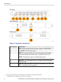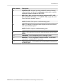
1
WFM2300 and WFM2200A
Multiformat Multistandard Portable Waveform
Monitor
Installation and Safety Instructions
99 Washington Street
Melrose, MA 02176
Phone 781-665-1400
Toll Free 1-800-517-8431
Visit us at www.TestEquipmentDepot.com
*P071320501*
071-3205-01
WFM2300 and WFM2200A
Multiformat Multistandard Portable Waveform
Monitor
Installation and Safety Instructions
Test Equipment Depot - 800.517.8431 - 99 Washington Street Melrose, MA 02176
TestEquipmentDepot.com
This document supports software
version 2.9 and above.
Table of Contents
Important safety information ..............................................................
General safety summary ...............................................................
Service safety summary ................................................................
Terms in the manual ......................................................................
Symbols on the product .................................................................
Compliance Information ....................................................................
EMC compliance .........................................................................
Environmental compliance .........................................................
Preface ................................................................................................
Accessories ..................................................................................
International power cords ...........................................................
Optional accessories ...................................................................
Instrument options .......................................................................
3G ..........................................................................................
DATA ....................................................................................
DBE .......................................................................................
LOUD ....................................................................................
SFP ........................................................................................
Documentation .............................................................................
iii
iii
vi
vi
vi
vii
vii
viii
xi
xii
xiii
xiii
xiv
xiv
xiv
xiv
xiv
xiv
xv
Operating requirements
Electrical ratings .............................................................................
Power requirements ..................................................................
AC power .................................................................................
Battery power ...........................................................................
Environmental ratings ....................................................................
Physical specifications ...................................................................
Cleaning ....................................................................................
1
1
1
2
3
4
4
Installation
Connectors
......................................................................................
WFM2300 and WFM2200A Installation and Safety Instructions
5
i
Table of Contents
Power cord installation ...................................................................
Battery pack installation .................................................................
Battery charge level indicators ...............................................
Tripod installation ........................................................................
SFP module installation ...............................................................
SFP module removal ..............................................................
SFP module transportation .....................................................
Video system installation .............................................................
Line termination .....................................................................
Compatibility of BNC center pins ..........................................
To monitor the video bit stream of a serial receiver ...............
To monitor the embedded audio signal in a serial digital video
stream ................................................................................
To monitor the external reference signal ................................
To test cable margins ..............................................................
To genlock the SDI output signal to the external reference
signal .................................................................................
8
9
11
13
14
15
15
16
16
16
17
17
18
18
19
Power-on and power-off procedures
Power-on
Power-off
......................................................................................
......................................................................................
21
22
Front panel controls
Layout and usage ..........................................................................
Three levels of control .................................................................
Scope of controls ..........................................................................
ii
23
27
27
WFM2300 and WFM2200A Installation and Safety Instructions
Important safety information
This manual contains information and warnings that must be followed
by the user for safe operation and to keep the product in a safe
condition.
To safely perform service on this product, see the Service safety
summary that follows the General safety summary.
General safety summary
Use the product only as specified. Review the following safety
precautions to avoid injury and prevent damage to this product or any
products connected to it. Carefully read all instructions. Retain these
instructions for future reference.
Comply with local and national safety codes.
For correct and safe operation of the product, it is essential that you
follow generally accepted safety procedures in addition to the safety
precautions specified in this manual.
The product is designed to be used by trained personnel only.
Only qualified personnel who are aware of the hazards involved should
remove the cover for repair, maintenance, or adjustment.
Before use, always check the product with a known source to be sure it
is operating correctly.
This product is not intended for detection of hazardous voltages.
Use personal protective equipment to prevent shock and arc blast injury
where hazardous live conductors are exposed.
While using this product, you may need to access other parts of a larger
system. Read the safety sections of the other component manuals for
warnings and cautions related to operating the system.
When incorporating this equipment into a system, the safety of that
system is the responsibility of the assembler of the system.
WFM2300 and WFM2200A Installation and Safety Instructions
iii
Important safety information
To avoid fire or personal injury
Use proper power cord. Use only the power cord specified for this
product and certified for the country of use. Do not use the provided
power cord for other products.
Power disconnect. The power cord disconnects the product from the
power source. See instructions for the location. Do not position the
equipment so that it is difficult to operate the power cord; it must
remain accessible to the user at all times to allow for quick
disconnection if needed.
Use proper AC adapter. Use only the AC adapter specified for this
product.
Connect and disconnect properly. Do not connect or disconnect probes or
test leads while they are connected to a voltage source. Use only
insulated voltage probes, test leads, and adapters supplied with the
product, or indicated by Tektronix to be suitable for the product.
Observe all terminal ratings. To avoid fire or shock hazard, observe all
rating and markings on the product. Consult the product manual for
further ratings information before making connections to the product.
Do not apply a potential to any terminal, including the common
terminal, that exceeds the maximum rating of that terminal.
Do not float the common terminal above the rated voltage for that
terminal.
Do not operate without covers. Do not operate this product with covers or
panels removed, or with the case open.
Avoid exposed circuitry. Do not touch exposed connections and
components when power is present.
Do not operate with suspected failures. If you suspect that there is damage
to this product, have it inspected by qualified service personnel.
Disable the product if it is damaged. Do not use the product if it is
damaged or operates incorrectly. If in doubt about safety of the
product, turn it off and disconnect the power cord. Clearly mark the
product to prevent its further operation.
Before use, inspect test leads and accessories for mechanical damage
and replace when damaged. Do not use test leads if they are damaged,
if there is exposed metal, or if a wear indicator shows.
iv
WFM2300 and WFM2200A Installation and Safety Instructions
Important safety information
Examine the exterior of the product before you use it. Look for cracks
or missing pieces.
Use only specified replacement parts.
Replace batteries properly. Replace batteries only with the specified type
and rating.
Recharge batteries properly. Recharge batteries for the recommended
charge cycle only.
Do not operate in wet/damp conditions. Be aware that condensation may
occur if a unit is moved from a cold to a warm environment.
Do not operate in an explosive atmosphere.
Keep product surfaces clean and dry. Remove the input signals before
you clean the product.
Provide proper ventilation. Refer to the manual's installation instructions
for details on installing the product so it has proper ventilation.
Slots and openings are provided for ventilation and should never be
covered or otherwise obstructed. Do not push objects into any of the
openings.
Provide a safe working environment. Always place the product in a
location convenient for viewing the display and indicators.
Avoid improper or prolonged use of keyboards, pointers, and button
pads. Improper or prolonged keyboard or pointer use may result in
serious injury.
Be sure your work area meets applicable ergonomic standards. Consult
with an ergonomics professional to avoid stress injuries.
WFM2300 and WFM2200A Installation and Safety Instructions
v
Important safety information
Service safety summary
The Service safety summary section contains additional information
required to safely perform service on the product. Only qualified
personnel should perform service procedures. Read this Service safety
summary and the General safety summary before performing any
service procedures.
Use care when servicing with power on. Dangerous voltages or currents
may exist in this product. Disconnect power, remove battery (if
applicable), and disconnect test leads before removing protective
panels, soldering, or replacing components.
Terms in the manual
These terms may appear in this manual:
WARNING. Warning statements identify conditions or practices that
could result in injury or loss of life.
CAUTION. Caution statements identify conditions or practices that
could result in damage to this product or other property.
Symbols on the product
When this symbol is marked on the product, be sure to
consult the manual to find out the nature of the potential
hazards and any actions which have to be taken to avoid
them. (This symbol may also be used to refer the user to
ratings in the manual.)
The following symbols may appear on the product:
vi
WFM2300 and WFM2200A Installation and Safety Instructions
Compliance Information
This section lists the EMC (electromagnetic compliance), safety, and
environmental standards with which the instrument complies.
EMC compliance
EC Declaration of Conformity – EMC
Meets intent of Directive 2004/108/EC for Electromagnetic
Compatibility. Compliance was demonstrated to the following
specifications as listed in the Official Journal of the European
Communities:
EN 61326-1:2006, EN 61326-2-1:2006. EMC requirements for electrical
equipment for measurement, control, and laboratory use. 1 2 3
■
CISPR 11:2003. Radiated and conducted emissions, Group 1,
Class A
■
IEC 61000-4-2:2001. Electrostatic discharge immunity
■
IEC 61000-4-3:2002. RF electromagnetic field immunity
■
IEC 61000-4-4:2004. Electrical fast transient / burst immunity
■
IEC 61000-4-5:2001. Power line surge immunity
■
IEC 61000-4-6:2003. Conducted RF immunity
■
IEC 61000-4-11:2004. Voltage dips and interruptions immunity 4
EN 61000-3-2:2006. AC power line harmonic emissions
EN 61000-3-3:1995. Voltage changes, fluctuations, and flicker
1
2
3
4
This product is intended for use in nonresidential areas only. Use in residential areas may cause
electromagnetic interference.
Emissions which exceed the levels required by this standard may occur when this equipment is
connected to a test object.
For compliance with the EMC standards listed here, high quality shielded interface cables should be
used.
Performance Criterion C applied at the 70%/25 cycle Voltage-Dip and the 0%/250 cycle VoltageInterruption test levels (IEC 61000-4-11).
WFM2300 and WFM2200A Installation and Safety Instructions
vii
Compliance Information
Australia / New Zealand Declaration of Conformity – EMC
Complies with the EMC provision of the Radiocommunications Act
per the following standard, in accordance with ACMA:
■
CISPR 11:2003. Radiated and conducted emissions, Group 1,
Class A, in accordance with EN 61326- 1:2006 and EN
61326-2-1:2006.
Environmental compliance
This section provides information about the environmental impact of
the product.
Product end-of-life handling
Observe the following guidelines when recycling an instrument or
component:
Equipment recycling. Production of this equipment required the
extraction and use of natural resources. The equipment may contain
substances that could be harmful to the environment or human health if
improperly handled at the product’s end of life. To avoid release of
such substances into the environment and to reduce the use of natural
resources, we encourage you to recycle this product in an appropriate
system that will ensure that most of the materials are reused or recycled
appropriately.
viii
WFM2300 and WFM2200A Installation and Safety Instructions
Compliance Information
This symbol indicates that this product complies with the
applicable European Union requirements according to
Directives 2002/96/EC and 2006/66/EC on waste
electrical and electronic equipment (WEEE) and
batteries.
Battery recycling. This product may contain a rechargeable battery,
which must be recycled or disposed of properly. Please properly
dispose of or recycle the battery according to local government
regulations.
Perchlorate materials. This product contains one or more type CR
lithium batteries. According to the state of California, CR lithium
batteries are classified as perchlorate materials and require special
handling.
Transporting batteries. The capacity of the lithium ion secondary battery
shipped with this product is under 100 Wh. The lithium content of the
installed primary battery is under 1 g. Each battery meets the applicable
requirements of UN Manual of Tests and Criteria Part III Section 38.3.
Battery quantity is under the limit for shipment according to Section II
of the relevant Packing Instructions from the IATA Dangerous Goods
Regulations. Consult your air carrier for applicability and
determination of any special lithium battery transportation
requirements.
Restriction of hazardous substances
This product is classified as an industrial monitoring and control
instrument, and is not required to comply with the substance
restrictions of the recast RoHS Directive 2011/65/EU until
July 22, 2017.
WFM2300 and WFM2200A Installation and Safety Instructions
ix
Compliance Information
Test Equipment Depot - 800.517.8431 - 99 Washington Street Melrose, MA 02176
TestEquipmentDepot.com
x
WFM2300 and WFM2200A Installation and Safety Instructions
Preface
This document contains the following information about the Tektronix
WFM2300 and WFM2200A Mutliformat Multistandard Portable
Waveform Monitor:
■
Important safety precautions to avoid injury and prevent damage to
this product or any products connected to it
■
EMC (electromagnetic compliance), safety, and environmental
standards with which the instrument complies
■
Voltage, power, and environmental requirements to use the
product
■
External connection requirements
■
Installation procedures and examples
■
Power-on and power-off procedures
■
Front panel control descriptions
Figure 1: WFM2300 waveform monitor
WFM2300 and WFM2200A Installation and Safety Instructions
xi
Preface
Accessories
Unpack the instrument and check that you have received all of the
items listed in the following table. Check our Web site
(www.tektronix.com) for the most current information on product
accessories.
You may want to save the shipping carton and packing materials
(including the anti-static bag) in case you need to ship the instrument.
Accessory
Tektronix part number
WFM2300 and WFM2200A Multiformat Multistandard Portable
Waveform Monitor Installation & Safety Instructions
071-3205-XX
WFM200BA Rechargeable Battery Pack Instructions
075-1041-XX
WFM200BA Lithium-Ion Rechargeable Battery Pack
WFM200BA
AC Power Adapter
119-7910-XX
Power Cord 1
Not applicable
NOTE. See International power cords on page xiii for the type
of power cord included with your instrument.
1
xii
If you ordered Option 99, no power cord is provided.
WFM2300 and WFM2200A Installation and Safety Instructions
Preface
International power cords
Your instrument was shipped with one of the following power cord
options. Power cords for use in North America are UL listed and CSA
certified. Cords for use in areas other than North America are approved
by at least one authority acceptable in the country to which the product
is shipped.
■
Opt. A0 – North America power
■
Opt. A1 – Universal Euro power
■
Opt. A2 – United Kingdom power
■
Opt. A3 – Australia power
■
Opt. A5 – Switzerland power
■
Opt. A6 – Japan power
■
Opt. A10 – China power
■
Opt. A11 – India power
■
Opt. A12 – Brazil power
■
Opt. A99 2 – No power cord or AC adapter
CAUTION. To reduce risk of fire and shock, use the certified power cord
provided with the product.
Optional accessories
If you ordered any of the following optional accessories, the items were
shipped separately.
2
■
WFM200BA: Rechargeable Battery Pack
■
WFM200BC: External Battery Charger
■
WFM200FSC: Soft Carrying Case
When ordering the A99 option, it is the responsibility of the end user to be sure that a certified power
cord, for the country or region in which it is installed, is used with this instrument.
WFM2300 and WFM2200A Installation and Safety Instructions
xiii
Preface
Instrument options
The following options are available for the WFM2300 and the
WFM2200A.
3G
Adds support for 3G-SDI signal formats (Level A and Level B).
(Upgrades are available by a software option key.)
DATA
Adds Ancillary Data monitoring (including decoding of 708 and
608 Closed Captions, Teletext and OP47 Subtitles, AFD, and CGMSA), and ANC Data Inspector
DBE
Adds Dolby E analysis (including Metadata display, peak level
indication, and Dolby E timing measurement)
LOUD
Adds Audio Loudness monitoring capabilities including Loudness
Meter
SFP
Adds Optical input/output SDI module support (includes one SFP
module); an SFP module is available for additional purchase
(Tektronix part number 119-8280-00)
xiv
WFM2300 and WFM2200A Installation and Safety Instructions
Preface
Documentation
The following table lists some of the documentation that is available
for this product and lists where you can locate the document.
Table 1: Product documentation
Item
Purpose
Location
Installation and
Safety Instructions
(this manual)
Provides safety and compliance information with
hardware installation instructions and associated
safety warnings. This manual is available in English,
Japanese, Simplified Chinese, and Russian.
Printed manual
User Manual
Provides operation and application information. This
manual is available in English.
Available online
Online Help
In-depth instrument operation and UI help.
On the instrument
Specifications and Specifications and procedures for checking
Performance
instrument performance.
Verification
Technical Reference
Available online
Declassification and Provides information for sanitizing the product.
Security Instructions
Available online
Release Notes
Provides information about the key features and
known limitations of a specific software version
release.
Available online
WFM200BA
Rechargeable
Battery Pack
Instructions
Provides safety, operating, and recycling information Printed manual
for the Lithium-Ion battery pack.
WFM200BC
Provides safety and operating information for the
External Battery
optional, external battery charger.
Charger Instructions
WFM2300 and WFM2200A Installation and Safety Instructions
Printed manual
xv
Preface
Test Equipment Depot - 800.517.8431 - 99 Washington Street Melrose, MA 02176
TestEquipmentDepot.com
xvi
WFM2300 and WFM2200A Installation and Safety Instructions
Operating requirements
This section provides the specifications that you need to know to
operate your product safely and correctly. See the WFM2300 and
WFM2200A Specifications and Performance Verification Technical
Reference for additional information on specifications.
Electrical ratings
Power requirements
This instrument is intended to be powered by a 19 VDC input or by the
WFM200BA Lithium-Ion rechargeable battery pack.
However, the instrument will operate from any regulated DC voltage
between 11 V and 20 V. Input voltages below 18.5 V should not be
used while the WFM200BA battery pack is installed, as the battery
pack will discharge until it is below the input voltage level.
AC power
When the instrument operates from an external AC adapter, the
following power requirements apply:
WARNING. Fire can cause personal injury and/or property damage. To
prevent risk of fire, when using an external DC source other than the
provided AC adapter, make sure that it has a suitable current limiting
device (such as a fuse).
■
A single-phase power source with one current-carrying conductor
at or near earth-ground (the neutral conductor).
■
The power source frequency must be 50 or 60 Hz, the operating
voltage range must be from 100 to 240 VAC, continuous. The
typical power draw is 27 W. However, if you are operating the
instrument and charging a battery at the same time, the typical
power doubles to 54 W.
Test Equipment Depot - 800.517.8431 - 99 Washington Street Melrose, MA 02176
TestEquipmentDepot.com
WFM2300 and WFM2200A Installation and Safety Instructions
1
Operating requirements
WARNING. To reduce risk of fire and shock, make sure the mains
supply voltage fluctuations do not exceed 10% of the operating
voltage range.
■
Systems with both current-carrying conductors live with respect to
ground (such as phase-to-phase in multiphase systems) are not
recommended as power sources.
NOTE. Only the line conductor is fused for over-current protection.
The fuse is internal and not user replaceable. Do not attempt to
replace the fuse. If you suspect the fuse has blown, return the unit
to an authorized service center for repair.
■
Use the proper power cord with the AC adapter. See International
power cords on page xiii.
NOTE. See the WFM2300 and WFM2200A Specifications and
Performance Verification Technical Reference for additional
information on power and environmental requirements.
Battery power
This instrument can be powered by a Lithium-Ion rechargeable battery
pack. One WFM200BA battery pack is provided with the instrument. If
needed, you can purchase additional battery packs.
NOTE. For optimum performance, charge the battery pack completely
before using it for the first time or after prolonged storage.When
installed, the battery pack will charge whenever the supplied AC
adapter is connected, whether the instrument is On, Off, or in Standby
mode. The charging rate is unaffected by instrument operation.
If you are using the WFM200BA battery pack to power the instrument,
read the following battery safety notices. See the WFM200BA
Rechargeable Battery Pack Instructions for information about how to
properly operate and maintain the battery pack.
2
WFM2300 and WFM2200A Installation and Safety Instructions
Operating requirements
CAUTION.
To avoid damage to the battery pack, use only the waveform monitor or
the optional WFM200BC battery charger to charge the battery pack.
Do not connect any other voltage source to the battery pack.
To avoid overheating of the battery pack during charging, do not
exceed the maximum ambient temperature of 40 °C. The battery pack
will stop charging if it gets too hot.
The temperature at which the battery pack will stop charging varies
depending on the charging current and the battery heat dissipation
characteristics. This is particularly true when the instrument is being
operated while the battery pack is charging. The actual batterycharging temperature limit may be lower than 40 °C.
Environmental ratings
Table 2: Environmental performance
Category
Temperature
Humidity
Altitude
Standards or description
Operating
0 °C to +40 °C
Charging a battery
10 °C to +40 °C
Non Operating
–20 °C to +60 °C
Operating
20% to 80% RH (relative humidity) at up to +40 °C,
noncondensing
Non Operating
5% to 90% RH (relative humidity) at up to +60 °C,
noncondensing
Operating
Up to 10,000 feet (3,000 meters)
WFM2300 and WFM2200A Installation and Safety Instructions
3
Operating requirements
Category
Standards or description
Non Operating
Cooling
Up to 40,000 feet (12,000 meters)
Variable fans provide forced air circulation.
Intake vent openings are located on the left, right,
and bottom edges of the instrument. The vents on
any one edge are allowed to be blocked, as for
example, by the hand when using the hand strap or
along the bottom edge when the instrument is set
upright on a table.
Exhaust vents are located on the back of the
instrument and must not be blocked. The instrument
in it's rubber boot may be laid flat on a smooth
surface provided that clearances are met.
To allow for proper airflow, there must be at least
2 inches of clearance on both sides of the instrument,
and at least 2 inches of clearance from the top edge
of the instrument.
Physical specifications
Table 3: Physical characteristics
Characteristic
Dimensions
Weight
Standard
Height
8.5 inches (215.9 millimeters)
Width
8.2 inches (208.3 millimeters)
Depth
1.4 inches (35.6 millimeters)
Net
4 pounds (1.81 kilograms) including battery pack;
Battery pack weighs 1 pound (0.45 kilograms)
Shipping
12 pounds (5.4 kilograms), approximate, excluding
options and accessories
Cleaning
Cleaning is not required for the safe operation of the instrument.
However, if you wish to perform routine cleaning on the exterior of the
instrument, refer to the WFM2300 and WFM2200A User Manual.
4
WFM2300 and WFM2200A Installation and Safety Instructions
Installation
Your handheld instrument is shipped in a fully enclosed metal chassis
with a protective rubber boot. A flange with a threaded hole is provided
on the bottom panel for use with a tripod mount.
If you need to install your instrument in a custom application, such as a
console, be sure to provide adequate airflow and make sure the intake
air to the side vents does not exceed 40 °C. Do not block or restrict the
ventilating holes. See the Environmental Ratings section for cooling
and clearance requirements.
CAUTION. To prevent risk of fire, adequate airflow must be maintained.
Failure to provide adequate airflow to the instrument could cause the
instrument to shut down. Inadequate airflow includes placing the
instrument in any small, enclosed room that lacks a ventilation system,
such as a closet. If the airflow is restricted or blocked and the
instrument does not shut down, the risk of fire is increased and the
instrument could be permanently damaged.
Connectors
The following figure shows the location of the external connections to
the instrument. Use the reference numbers to locate the connector
descriptions in the following table.
WFM2300 and WFM2200A Installation and Safety Instructions
5
Installation
Figure 2: Instrument connections
Item number
Description
1
SFP. The optical SDI input and output compliant to SMPTE297. 1
2
11–20 VDC. The DC power input.
3
REF IN. A synchronization input. The input signal can be analog
black burst, analog composite video, or analog tri-level for HD.
NOTE. The reference input is a self-terminating input.
1
2
6
4
AES OUT. The AES audio output. The signal complies with ANSI/
SMPTE 276M.
5
SDI OUT. Select to output Loop Out or Test Signals for SD-SDI, HDSDI, or 3G-SDI (Level A or level B). 2
The SFP optical SDI input and output is available with Option SFP installed.
3G-SDI support is available with Option 3G installed.
WFM2300 and WFM2200A Installation and Safety Instructions
Installation
Item number
Description
6
STRESS LOOP. A stress loop that provides 20 meters of coaxial
cable simulation and allows for cable margin testing with a variable
amplitude interfering signal per SMPTE292.
7
MULTI IN. A BNC connector that can be configured as SDI, AES/
EBU (ANSI/SMPTE 276M) or LTC (SMPTE 12M-1) input with multiformat and multi-standard support.2
NOTE. The MULTI IN input is a self-terminating input.
8
SDI A. The digital A component serial digital input with multi-format
and multi-standard support.2
NOTE. The SDI A input is a self-terminating input.
9
USB. A USB connector for use with external devices such as thumb
drives.
10
Headphone. A mini headphone jack for listening to audio.
11
Ethernet. A 10/100/1000 BaseT Ethernet interface. The Ethernet
connector is a standard RJ-45 connector.
12
Tripod mount. A ¼-20 threaded hole for mounting the instrument on
a camera tripod.
WFM2300 and WFM2200A Installation and Safety Instructions
7
Installation
Power cord installation
Connect the AC adapter to the power connector on the instrument top
panel as shown below.
NOTE. If a battery pack is installed in the instrument, it will
automatically charge whenever the supplied AC adapter is connected,
whether the instrument is On, Off, or in Standby mode.
8
WFM2300 and WFM2200A Installation and Safety Instructions
Installation
Battery pack installation
The waveform monitor is shipped with a WFM200BA Lithium-Ion
rechargeable battery pack. Perform the following steps to install the
battery pack.
WARNING. For optimum performance, charge the battery pack
completely before using it for the first time or after prolonged storage.
The battery pack can be installed, removed, or replaced while the
instrument is turned on and operating with the AC adapter. See the
WFM200BA Rechargeable Battery Pack Instructions for more
information about the battery pack.
1.
On the rear panel of the instrument, remove the cover for the
battery compartment:
a.
Use your fingers or a coin to turn the battery cover screw
counterclockwise until the cover is loose.
b. Lift away the battery cover.
2.
Insert the WFM200BA battery pack into the battery compartment
as shown below.
WFM2300 and WFM2200A Installation and Safety Instructions
9
Installation
3.
Secure the battery pack tab as shown below.
4.
Replace the battery compartment cover:
a.
Insert the three tabs on the battery cover into the chassis slots
as shown below.
Test Equipment Depot - 800.517.8431 - 99 Washington Street Melrose, MA 02176
TestEquipmentDepot.com
10
WFM2300 and WFM2200A Installation and Safety Instructions
Installation
b. Close the battery cover and then use your fingers or a coin to
turn the battery cover screw clockwise to secure the cover as
shown below.
Battery charge level indicators
When the WFM200BA battery pack is not installed in the instrument,
you can check the charge level by pressing the Check button on the
back of the battery pack. LEDs will illuminate to indicate the amount
of charge remaining in increments of approximately 20%.
WFM2300 and WFM2200A Installation and Safety Instructions
11
Installation
When a battery pack is installed in the instrument, the charge level
meter is shown on the bottom right of the status bar. The following
table shows examples of the meter icons.
Table 4: Battery charge-level meter icons
Item
Description
Battery fully charged, AC adapter plugged in
Battery partially charged, AC adapter plugged in and charging
Battery level low, AC adapter not plugged in
Battery level critically low, AC adapter not plugged in
12
WFM2300 and WFM2200A Installation and Safety Instructions
Installation
Tripod installation
The bottom panel provides a ¼-20 threaded hole that can be used to
mount the instrument on a camera tripod as shown below.
WFM2300 and WFM2200A Installation and Safety Instructions
13
Installation
SFP module installation
With Option SFP, you receive an SFP module for monitoring optical
SDI signals.
To install the SFP module, you will first need to remove the plug from
the SFP connector. Insert the SFP module into the SFP connector on
the top-panel of the waveform monitor as shown below. The module
will latch into place when fully inserted.
14
WFM2300 and WFM2200A Installation and Safety Instructions
Installation
SFP module removal
To remove the SFP module, lift up on the latch and then pull the
module out of the SFP connector as shown below.
SFP module transportation
The SFP module should be removed from the waveform monitor while
the instrument is being transported.
CAUTION. To prevent static damage to the SFP module while you are
transporting the waveform monitor, always transport the SFP module
in a anti-static bag or container.
WFM2300 and WFM2200A Installation and Safety Instructions
15
Installation
Video system installation
The waveform monitor can operate almost anywhere in the distribution
system where serial digital system monitoring is needed.
Line termination
The line termination of the signal inputs are as follows:
■
SDI A and REF IN: Each input has a 75 Ω internal termination.
■
MULTI IN: The input auto-terminates based on the type of input
signal.
■
SFP (optional): The termination of the optional SFP input is
determined by the installed module. No termination occurs for
optical inputs.
Compatibility of BNC center pins
Most BNC connectors for video equipment, whether 50 Ω or 75 Ω, use
a 50 Ω standard center pin. Some laboratory 75 Ω BNC connectors use
a smaller diameter center pin. The BNC connectors on the instrument
are designed to work with the 50 Ω standard (large diameter) center
pins.
Do not use connectors or terminators with the smaller center pins. They
could cause intermittent connections.
16
WFM2300 and WFM2200A Installation and Safety Instructions
Installation
To monitor the video bit stream of a serial receiver
Route one or more incoming serial signals into the SDI inputs on the
instrument.
NOTE. See the WFM2300 and WFM2200A Specifications and
Performance Verification Technical Reference for the maximum
allowed cable lengths.
To monitor the embedded audio signal in a serial digital video
stream
Route the incoming serial signal into one of the SDI inputs on the
instrument.
WFM2300 and WFM2200A Installation and Safety Instructions
17
Installation
To monitor the external reference signal
Route the incoming reference signal into the REF IN input on the
instrument.
To test cable margins
To test the cable margins for a monitored signal, route the incoming
signal input to one of the STRESS LOOP connectors. Route a cable
from the other connector of the STRESS LOOP to the SDI A input as
shown below.
Figure 3: Stress loop connections for a monitored signal
18
WFM2300 and WFM2200A Installation and Safety Instructions
Installation
To test the cable margins for a generated signal, route the SDI OUT
signal to one of the STRESS LOOP connectors. Route a cable from the
other connector of the STRESS LOOP to your video system as shown
below.
Figure 4: Stress loop connections for a generated signal
To genlock the SDI output signal to the external reference signal
To genlock the SDI output signal to the external reference signal, use
the CONFIG > Outputs > Test Signal Genlock menu to enable the
genlock function and to configure the genlock vertical and horizontal
timing offsets. The Generator Status display and the Status Bar indicate
the status of the genlock function.
WFM2300 and WFM2200A Installation and Safety Instructions
19
Installation
Test Equipment Depot - 800.517.8431 - 99 Washington Street Melrose, MA 02176
TestEquipmentDepot.com
20
WFM2300 and WFM2200A Installation and Safety Instructions
Power-on and power-off procedures
This instrument can be powered by the DC output of an AC adapter or
by the WFM200BA rechargeable battery pack. See Electrical ratings
on page 1 for information about power requirements.
Power-on
1.
Connect power to the instrument:
■
AC adapter: Connect the AC adapter to the power connector
on the instrument. See Power cord installation on page 8.
■
Battery pack: Install the WFM200BA battery pack. See
Battery pack installation on page 9.
NOTE. If you are powering the instrument using only the
battery pack, check the power level before operating the
instrument. See Battery charge level indicators on page 11.
2.
Press the Power button on the instrument front panel to turn the
instrument on.
WFM2300 and WFM2200A Installation and Safety Instructions
21
Power-on and power-off procedures
Power-off
There are two methods for powering off the instrument:
■
Press the Power button on the front panel. This opens the Power
off or Standby dialog box where you can use the arrows buttons to
select from the following actions:
NOTE. When you press the Power button, you must make a
selection in the Power off or Standby dialog box within 5 seconds
or the instrument will automatically power off.
■
■
Power off. This is the default selection. You can press the
SEL button to immediately power off the instrument or you
can wait 5 seconds for the instrument to automatically power
off.
■
Standby. Use the arrow buttons to select Standby to put the
instrument in Standby mode. In Standby mode, the instrument
consumes less power than when it is turned on and also takes
less time to turn back on than when the instrument is turned
completely off.
■
Cancel. Use the arrow buttons to select Cancel if you want to
cancel the power-off operation.
Press and hold the Power button for 5 seconds and then release the
button to immediately power off the instrument.
NOTE. To remove power completely from the instrument, disconnect the
AC adapter from the power connector and remove any installed battery
pack.
22
WFM2300 and WFM2200A Installation and Safety Instructions
Front panel controls
NOTE. Some of the controls that this section covers are option
dependant. For a list of the options that are installed on your
instrument, press the CONFIG button. In the configuration menu,
select the Utilities submenu. The View Options entry lists the options
installed on your instrument.
Layout and usage
The front panel elements shown below are described in the table that
follows.
Figure 5: WFM2300 front panel
WFM2300 and WFM2200A Installation and Safety Instructions
23
Front panel controls
Control Element or Group
Description
PRESET
Press to save or recall presets using the bezel buttons. Press
and hold to access the Preset menu.
WFM
Press to display either the waveform of the selected video input,
the LTC input, or the video reference input. Press and hold to
access the Waveform pop-up menu.
VECTOR
Press to display the Vector or Lightning plots of the video color
signals. Press and hold to access the Vector pop-up menu.
PICT
Press to display the picture generated by the video signal input.
Press and hold to access the Picture pop-up menu.
AUDIO
Press to display level meters and a phase plot or surround
display of the audio signal. Press and hold to access the Audio
pop-up menu.
GAMUT
Press to check the gamut of an SDI video signal. Select from
one of three proprietary Tektronix displays: Arrowhead,
Diamond, and Split Diamond. Press and hold to access the
Gamut pop-up menu.
STATUS
Press to view signal status and information. Press and hold to
access the Status pop-up menu.
MEAS
Press to view Tektronix proprietary displays that simplify timing
correction. The Timing Measure and Bowtie displays are
standard with each instrument. Option DATA adds the Data List
and ANC Data displays. Press and hold to access the Measure
pop-up menu.
GEN
Press to view or modify the status and configuration of the SDI
video and AES audio test signal generators. Press and hold to
access the Generator pop-up menu.
PHY
This button appears only on WFM2300 instruments. Press to
view the physical layer measurements of SDI signals. The Eye
and Jitter displays provide automated measurement readouts.
Press and hold to access the Physical pop-up menu.
SWEEP
Press to toggle the horizontal sweep mode of the video
waveform between lines and fields. Press and hold to access the
Sweep pop-up menu where you can set the display style
(parade or overlay).
24
WFM2300 and WFM2200A Installation and Safety Instructions
Front panel controls
Control Element or Group
Description
MAG
Press to toggle the horizontal magnification for the Waveform
and Lightning displays. Press and hold to access the
Magnification pop-up menu where you can select the
magnification setting.
GAIN
Press to toggle the gain of the Waveform, Vector, Lightning, and
Bowtie displays. Press and hold to access the Gain pop-up
menu.
VAR
Press to enable or disable the Variable Gain function. When
enabled, use the General knob to adjust the signal gain.
LINE
Press to enable or disable the Line Select mode. When enabled,
use the General knob and arrow buttons to select which line and
field to display. In the Datalist display, press the SEL button to
toggle between line and sample select.
CURSOR
Press to enable or disable the measurement cursors. When
enabled, use the General knob and the arrow buttons to adjust
the cursor positions. Press and hold to access the Cursor popup menu.
HELP
Press to display context-sensitive online help for the selected
display mode or menu item. Use the General knob and the arrow
buttons to navigate the online help content. When online help is
displayed, you can press most of the front panel buttons to
access information about those buttons.
CAPTURE
Press to capture an image of the selected display. Press and
hold to access the Capture pop-up menu where you can
compare a captured display image with the live display.
DISPLAY SETUP
Press to access the Display pop-up menu. Use the menu
selections to adjust various display levels, to enable the Infinite
Persistence mode, and to save a copy of the instrument display
to a device connected to the USB port.
MAIN SETUP
Press to access the Main pop-up menu. Use the menu
selections to select the tile display mode, to check the USB port
status, and to configure the function of the Display Select button
(selecting a display or turning the Thumbnail view on/off).
CONFIG SETUP
Press to access the Configuration pop-up menu. Use the menu
selections to configure various instrument parameters, to check
for installed options, to set network parameters, to perform a
system upgrade, and more.
WFM2300 and WFM2200A Installation and Safety Instructions
25
Front panel controls
Control Element or Group
Description
INPUT A / INPUT B
Press to select which video input to monitor: SDI A or SDI B.
EXT REF
Press to toggle the synchronization source between the internal
reference signal or the analog video reference signal connected
to the REF IN input.
Display Select
Press to move the tile selection from one tile to another. Press
and hold to toggle between Full Screen and 4-Tile display
modes.
The default setting for this button is as a tile select button. This
button can also be configured using the MAIN button menu to
toggle the thumbnail view of the picture on and off in the
selected tile. The position of the thumbnail is determined
automatically.
Arrow Buttons and SEL Button Press the arrow buttons to navigate between menu panes and
selections or to increment/decrement values. Press the SEL
button to set the selected parameter.
General knob
Turn to select or adjust a parameter and to navigate through a
menu or online help. When the General knob is enabled, a knob
icon appears next to the enabled parameter to indicate which
parameter is controlled by the knob.
POS
Press this button, and then use the General knob to position
traces on the Waveform, Vector, Lightning, and Bowtie displays.
Use the up/down arrow buttons for finer adjustments and use the
left/right arrow buttons to switch between horizontal and vertical
adjustments.
VOL
Press this button, and then use the General knob and the up/
down arrow buttons to adjust the volume. When the Audio tile is
selected and no menus are active, the General knob controls the
volume.
When monitoring high-amplitude audio, volume levels over 90%
may cause audio clipping.
WARNING. To prevent risk of hearing damage, always turn
down the headphone audio level before connecting a
headphone into the headphone jack. Sound levels and
impedance can vary between headphones.
Power button
26
Press to put the instrument in Standby mode or to turn the power
on or off. See Power-on and power-off procedures on page 21.
WFM2300 and WFM2200A Installation and Safety Instructions
Front panel controls
Three levels of control
You control the instrument on three levels:
■
Frequently changed settings. The front panel buttons control the
most commonly changed parameters, such as which measurement
appears in each tile. Use the knob and navigation buttons to adjust
levels and make selections.
■
Tile-specific settings. Pop-up menus control parameters that are
specific to the tile in which they are displayed. The pop-up menus
control less frequently changed parameters such as the waveform
display mode (for example, changing the waveform display mode
from RGB to YPbPr). To display a pop-up menu, press and hold
the desired button for about two seconds.
■
Instrument-wide settings. The parameters in the Configuration
menu are instrument-wide settings. The configuration menu
controls settings that are changed only occasionally, such as
changing waveform color or setting the network address.
Scope of controls
Some controls are global and affect all tiles, while other controls only
affect the active tile. Generally speaking, if a control is configured by
front panel buttons or by a pop-up menu, it is tile specific. (Exceptions
are the Input and Ref buttons, and all audio and generator features,
each of which are global.)
If a control is configured by the Configuration menu, the selections are
always global. The settings in the Display, Main, and Preset menus are
also global.
The Capture button can be either global or tile specific depending on
the setting in the Configuration menu (Display Settings > Freeze
Affects).
WFM2300 and WFM2200A Installation and Safety Instructions
27
Front panel controls
Test Equipment Depot - 800.517.8431 - 99 Washington Street Melrose, MA 02176
TestEquipmentDepot.com
28
WFM2300 and WFM2200A Installation and Safety Instructions