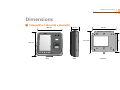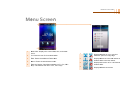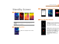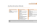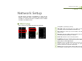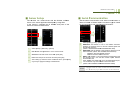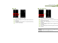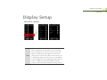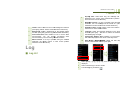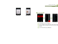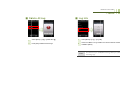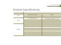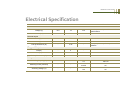
1
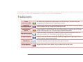
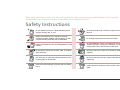
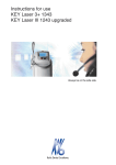
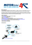
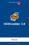
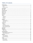
BioStation T2 is the IP network-based premium fingerprint verification terminal that delivers various authentication modes such as fingerprint, RFID, and PIN authentication for access control and time & attendance. Features 5 inch touchscreen LCD An intuitive GUI provided on the high-durable 5 inch touchscreen LCD delivers easy user management and displays various information and notices. Camera for face image capture The built-in high-performance camera detects the face image and captures image logs which delivers enhance security through valid identification check. Embedded Web Server The embedded web server (BioStar Lite) allows administrators to manage users and devices through a web browser in any PC without S/W and database installation. Fast matching speed Versatile Interfaces Video Phone RF Card Options Loaded with world’s best performing Suprema fingerprint algorithm and powerful dual CPU achieves unparalleled 1:3,000 fingerprint matches in less than a second. Provides various interfaces, such as PoE, WiFi, TCP/IP, and RS485/232, allowing users to connect to PCs and configure the network. In addition, Wiegand and I/O ports allow users to configure various access control systems. Provides IP-based AV interface and analog video phone functions. Supports EM, Mifare Classic, Mifare Plus, and Mifare DesFire(CSN) cards. 1 These safety instructions provided here are meant to guard your safety and prevent any possible damage or loss of property. Please carefully read these and keep them in mind when you use Suprema’s product. Safety Instructions Do not install the terminal in a place affected by direct sunlight, humidity, dust, or soot. Do not drop the terminal or cause any impact on the terminal. Keep the terminal away from magnets or anything containing magnetic material, such as magnet, TV sets, computer monitor (especially CRT) and speakers. Do not apply heavy pressure to the touch screen. Keep the terminal away from any heating devices or heat sources. Do not disassemble, repair, or reconstruct the terminal without any direction of Suprema. Otherwise, you cannot receive proper A/S for the terminal from Suprema. Do not spill any liquids such as soda, water, or solutions into the terminal. Keep the product out of reach from children for safety purposes. Use a soft cloth or towel when cleaning the terminal. Do not spray water on the terminal. Do not use the terminal for any other purpose than its original use. Clean the terminal regularly to prevent dust from settling onto it. In case of product malfunction or problems, please contact Suprema’s Customer Service Center or the sales agent. 2 1 Before Getting Started ................................................................ 6 Components................................................................................. 7 ■ Basic Components ................................................................ 7 ■ Optional Accessories ............................................................ 9 Names and Functions of Parts .................................................. 10 ■ Front .................................................................................... 10 ■ Bottom ................................................................................. 11 ■ Rear .................................................................................... 11 Dimensions ................................................................................ 12 Menu Screen.............................................................................. 14 Standby Screen ......................................................................... 16 Authentication Mode .................................................................. 17 How to place a finger ................................................................. 18 Table of Contents 2 Installation .................................................................................. 20 Installation .................................................................................. 21 Connector/Cable Specifications................................................. 22 ■ 232 CABLE (3-pin Connector) ............................................ 22 ■ SWITCH CABLE (8-pin Connector) .................................... 22 ■ RELAY CABLE (3-pin Connector)....................................... 23 ■ WIEGAND CABLE (5-pin Connector) ................................. 23 ■ POWER CABLE (2-pin Connector) .................................... 23 ■ VIDEO PHONE CABLE (7-pin Connector) ......................... 24 3 ■ RS485 CABLE (4-pin Connector) ....................................... 24 Access Authentication................................................................ 43 Connection ................................................................................. 25 Fingerprint Authentication ...................................................... 43 ■ Power Connection (2-pin Connector) .................................. 25 ■ Fingerprint Only .................................................................. 43 ■ USB Cable Connection ....................................................... 26 ■ Fingerprint + Pin Authentication .......................................... 43 ■ Ethernet Connection (Ethernet Cable) ................................ 27 ■ T&A Key+Fingerprint Authentication ................................... 44 ■ Ethernet Connection (Direct connection to PC) .................. 28 ■ T&A Key + Fingerprint + Pin Authentication ........................ 44 ■ PoE hub connection ............................................................ 29 Card Authentication ................................................................ 44 ■ Wireless Connection ........................................................... 30 ■ Card Only Authentication .................................................... 44 ■ USB Memory Connection.................................................... 31 ■ Card + Password Authentication......................................... 45 ■ RS485 PC Connection (4-pin Connector) ........................... 32 ■ Card + Fingerprint Authentication ....................................... 45 ■ RS485 Connection to Secure I/O ■ Card + Fingerprint/Password Authentication ...................... 46 or Other Terminals (4-pin Connector) ................................... 33 ■ Card + Fingerprint + Password Authentication ................... 46 ■ RS232 Connection .............................................................. 34 ID Authentication .................................................................... 47 ■ Videophone Connection ...................................................... 35 ■ ID + Password Authentication ............................................. 47 ■ Relay Connection - Fail Safe Lock (3-pin Connector) ........ 36 ■ ID + Fingerprint Authentication ........................................... 47 ■ Relay Connection - Fail Secure Lock (3-pin Connector) .... 36 ■ ID + Fingerprint/Password Authentication........................... 48 ■ Relay Connection – Automatic Door (3-pin Connector) ...... 37 ■ ID + Fingerprint + Password Authentication ....................... 48 ■ TTL Switch Input Connection (8-pin Connector) ................. 38 T&A Mode .................................................................................. 49 ■ Wiegand Input (5-pin Connector) ........................................ 39 ■ T&A Mode Setup ................................................................. 49 ■ Wiegand Output (5-pin Connector) ..................................... 39 ■ T&A Authenticate Methods.................................................. 50 System Configuration ................................................................. 40 ■ T&A Event ........................................................................... 50 ■ Standalone .......................................................................... 40 ■ Personal Entrance/T&A Record Check ............................... 51 ■ Secured ............................................................................... 40 Authentication Failures .............................................................. 52 ■ Network Configuration......................................................... 41 4 Admin Menu ................................................................................ 53 3 User Menu ................................................................................... 42 Registering an Admin ................................................................. 54 4 ■ Entering into Admin Menu ................................................... 55 ■ T&A Mode ........................................................................... 80 ■ Configuration of Admin Menu .............................................. 57 ■ T&A Event ........................................................................... 80 User Enrollment process............................................................ 59 ■ Camera Event ..................................................................... 81 Registering User to Device (using CSN) ................................... 60 Device Setup.............................................................................. 82 ■ Enroll User........................................................................... 61 ■ Fingerprint Setting ............................................................... 82 ■ Edit/Delete User .................................................................. 64 ■ Door .................................................................................... 84 ■ Search User ........................................................................ 65 ■ Interphone Setting ............................................................... 85 ■ Checking the Registered User Info ..................................... 67 ■ Date & Time Setup .............................................................. 86 ■ Deleting All Users ................................................................ 67 ■ Device Info .......................................................................... 87 Registering a User to a Card (using Template Card) ................. 69 ■ Memory Info ........................................................................ 87 ■ Issuing a Card ..................................................................... 69 ■ Touchscreen Calibration ..................................................... 87 ■ Formatting a Card ............................................................... 71 ■ Touchkeypad Calibration ..................................................... 87 Network Setup............................................................................ 72 ■ Reset ................................................................................... 88 ■ TCP/IP Setup ...................................................................... 72 ■ Factory Default .................................................................... 88 ■ Server Setup ....................................................................... 74 Display Setup ............................................................................. 89 ■ Serial Communication ......................................................... 74 Log ............................................................................................. 90 ■ USB ..................................................................................... 75 ■ Log List................................................................................ 90 ■ USB Memory ....................................................................... 75 ■ Log Search .......................................................................... 91 ■ Wireless LAN....................................................................... 76 ■ Delete All Log ...................................................................... 92 Authentication Mode .................................................................. 77 ■ Log Info ............................................................................... 92 ■ Finger Auth Mode ................................................................ 77 ■ Card Auth Mode .................................................................. 78 ■ ID Auth Mode....................................................................... 78 ■ Operation............................................................................. 79 5 Appendix ..................................................................................... 93 Product Specifications ............................................................... 94 Electrical Specification ............................................................... 95 5 BioStation T2 User Guide http://www.supremainc.com 1 Before Getting Started 6 BioStation T2 User Guide 1 Before Getting Started Please check the package and ensure that all of the components are prepared. Components ■ Basic Components CARD Software CD (1 copy) BioStation T2 Body Wall Bracket Screws and PVC Anchors (4 EA each) Mini USB Cable Ferrite Core Cables (7 types, 9 EA) 7 BioStation T2 User Guide 1 Before Getting Started 8 BioStation T2 User Guide 1 Before Getting Started ■ Optional Accessories Plastic Stand Secure I/O USB Mifare Reader/Writer USB fingerprint scanner (for enrollment on PC) Access Point (For Wireless Model only) RF Cards Analog Video Phone Power Adapter Note The product shown above is just an image to illustrate the product. Depending on Suprema’s internal changes, some of the components shown here may be different and changed from the components that you have received. 9 BioStation T2 User Guide 1 Before Getting Started Names and Functions of Parts ■ Front No. Name 1 Microphone Function Used for interphone call. 2 Proximity Sensor A sensor that detects objects around the device without any physical contact. To reduce power consumption, BioStation T2 lowers the brightness of the backlight when no input is made for a specified time. 3 Camera Used for still image logs and video interphone. 4 Card reader 5 Fingerprint Sensor LED 6 Speaker 7 Fingerprint Sensor 8 CALL Key 9 T&A Keys (F1~F4) Used as function keys to select the T&A event 10 Color LCD Screen Displays time, status, and UI for operation. Reads a RF card. Displays the status of the fingerprint sensor. 1)ON – Waiting for fingerprint input 2)Blinking – Requesting for a specific fingerprint or fingerprint for registration Outputs sound effects and voices. Used to register and authenticate a user's fingerprint. Used to make a call when a video phone is connected. 10 BioStation T2 User Guide 1 Before Getting Started ■ Bottom 1 ■ Rear 2 No. Name 1 USB type A A slot to connect a USB memory 2 Mini USB A slot to connect a PC to a USB. No. Name 1 USB Wireless LAN port 2 RJ45 Socket 3, 4 3-pin Connector Connects RELAY(0,1) 5, 6 4-pin Connector Connects RS485(0,1) 7, 8 Termination Switch 9 8-pin Connector SWITCH Input 10 3-pin Connector Connects RS232 port 11 7-pin Connector Connects VIDEOPHONE 12 5-pin Connector WIEGAND Input/Output 13 2-pin Connector Slot for Micro SD Memory Card Connects power supply Used to insert Micro SD-type memory card for extended functions. 14 Function Function A slot to connect the USB wireless LAN device. For the wireless LAN-supported BioStation T2 model, the wireless LAN device is mounted before released from the factory. Connects Ethernet cable RS485 TERMINATION Enable/Disable 11 BioStation T2 User Guide 1 Before Getting Started Dimensions ■ 155mm(W) x 155mm(H) x 40mm(D) 155 mm 40 mm 135 mm 134.2 mm 109 mm 155 mm Rear Side Bracket 12 BioStation T2 User Guide 1 Before Getting Started 13 BioStation T2 User Gu uide 1 Before Getting Starrted Me enu Screen n 1 2 3 4 5 1 2 Status Bar: Displa S ays the current datte, time, and statu us ic cons. ID: Enters the use er ID for authentica ation. Displays whether w or not to use face detection option for image logs. l 3 T T&A: Enters the additional T&A eve ents. 2 4 M Menu: Enters the administrator men nu. E connectio on status and Displays Ethernet wireless LAN L connection sttatus. 3 5 T&A Key Display: Describes operattions of F1~F4, CA T ALL k keys. The buttons work like F1~F4, CALL keys. Displays connection c to PC via Ethernet and wireless LAN. L 1 4 Displays RS485 R connection n. 14 BioStation T2 User Guide 1 Before Getting Started 15 BioStation T2 User Gu uide 1 Sta andby y Scre een Before Getting Starrted ■ Setting g the Backg ground Sc creen ■ Sta art-up Scre een Notic ce T Theme 1 No ote The eme 2 Them me 3 Theme 4 When time is hidden from the ccenter of the screen for Theme 1 and Theme 3, the movving background screen is dissplayed. Slide PDF S Sc creens ■ Other Standby e terminal using Locked: You can lock the pers position or a specific input the tamp port. To unlock the termin nal, administtrator’s authentica ation is required. ■ T&A A Configuration The T& &A event is displa ayed under the sta atus bar. Armed: When a security area is set, you can change the mode of the t terminal to the secu urity mode. To rele ease the security mode, authentica ation by a user who belo ongs to the corres sponding security group is required d. For morre details, see the BioStar manual. 16 BioStation T2 User Guide 1 Before Getting Started Authentication Mode BioStation T2 supports various authentication modes using fingerprints, RFID card, and ID (PIN). Fingerprint Authentication Mode Card Authentication Mode ID Authentication Mode ■ Finger: Only fingerprints are used for authentication. ■ Finger+Pin: For authentication, input the fingerprint and then type the password. ■ Card Only: Only a RF card is used for authentication. ■ Card+Pin: For authentication, place the registered card onto the card reader and then type the password. ■ Card+Finger: For authentication, place the registered card onto the card reader and then input the fingerprint. ■ Card+Fnger/Pin: For authentication, place the registered card onto the card reader and then input the fingerprint or type the password. ■ Card+Finger+Pin: For authentication, place the registered card onto the card reader, and then input the fingerprint and type the password. ■ ID+Pin: For authentication, type the registered ID and then type the password. ■ ID+Finger: For authentication, type the registered ID and then input the fingerprint. ■ ID+Finger/Pin: For authentication, type the registered ID and then input the fingerprint or type the password. ■ ID+Finger+Pin: For authentication, type the registered ID, and then input the fingerprint and type the password. Note For more detailed description on each authentication mode, see [Chapter 3, User Menu > Access Authentication (p.40)]. 17 BioStation T2 User Guide 1 Before Getting Started How to place a finger ■ Select a finger to enroll (3) If a finger is placed as in the right picture, only a small area of a finger is captured. So it is recommended to place a finger as in the left picture. Right (1) It is recommended to use an index finger or a middle finger. (2) Thumb, ring or little finger is relatively more difficult to place in a correct position. ■ How to place a finger on a sensor (1) Place a finger as it completely covers the sensor with maximum contact. (2) It is better to place the core part of a fingerprint to the center of a sensor. z People usually tend to place only the top end of a finger z Where is the core (center) of a fingerprint? A peak where spirals of fingerprint ridges are dense Usually opposite to lower part of a nail It is recommended to place a finger as the lower part of a nail is located at the center of a sensor Wrong ■ Tips for different finger conditions Suprema’s fingerprint products are designed to scan fingerprint smoothly regardless of the conditions of a finger skin. However, if a fingerprint is difficult to scan due to other influences, please refer to the followings tips. (1) If a finger is stained with sweat or water, scan after wiping moisture off. (2) If a finger is covered with dust or impurities, scan after wiping them off. (3) If a finger is way too dry, scan after blowing warm breath on a fingertip. 18 BioStation T2 User Guide 1 Before Getting Started ■ Advices on fingerprint enrollment (1) In fingerprint recognition, enrollment process is very important. Therefore, when enrolling a fingerprint, please try to place a finger correctly with care. (2) In case of low acceptance ratio, the following actions are recommended. z Delete enrolled fingerprints and re-enroll the fingers. z Enroll the same finger additionally z Try with another finger if a finger is not easy to enroll due to scar or worn-out. (3) For the case when an enrolled fingerprint can’t be used due to scar or holding a baggage, it is recommended to enroll more than two fingers. 19 BioStation T2 User Guide http://www.supremainc.com 2 Installation 20 BioStation T2 User Guide 2 Installation Installation BioStation T2 has a camera for face detection and video interphone. Therefore, height of the product and its camera angle are very important factors in installation. For easy face detection and fingerprint authentication, determine the place where the product should be installed. We recommend you to install the product at the height of 130 cm ~ 140 cm from the floor and the minimum distance between the product and the human is 40 cm. 1. Adjust the wall mounted bracket to the desired place on the wall and then fix it firmly to the wall. 2. Attach the product on the fixed wall mounted bracket and fix 21 BioStation T2 User Guide 2 it to the bracket using the screw located at the bottom of the Installation wall mounted bracket. Connector/Cable Specifications ■ 232 CABLE (3-pin Connector) Pin Name 1 232RX 2 232TX 3 GND Cable Type Color GREEN AWG26 YELLOW BLACK ■ SWITCH CABLE (8-pin Connector) Pin Name Cable Type 1 SWITCH INPUT0 YELLOW 2 SWITCH INPUT1 GREEN 3 SWITCH GND BLACK 4 SHIELD GND 5 SWITCH INPUT2 6 SWITCH INPUT3 ORANGE 7 SWITCH GND BLACK 8 SHIELD GND GRAY AWG26 Color GRAY WHITE 22 BioStation T2 User Guide 2 Installation ■ RELAY CABLE (3-pin Connector) Pin Name 1 RELAY NORMAL OPEN 2 RELAY COMMON 3 RELAY NORMAL CLOSE Cable Type Color WHITE AWG24 BLUE ORANGE ■ WIEGAND CABLE (5-pin Connector) Pin Name 1 DATA0 2 DATA1 3 GND 4 SHIELD GND Cable Type Color GREEN AWG26 WHITE BLACK GRAY ■ POWER CABLE (2-pin Connector) Pin Name 1 POW + 2 POW - Cable Type Color RED AWG24 BLACK 23 BioStation T2 User Guide 2 Installation ■ VIDEO PHONE CABLE (7-pin Connector) Pin Name Cable Type 1 VOICE SIGNAL RED 2 GND BLUE 3 POWER YELLOW 4 VIDEO SIGNAL 5 DOOR OPEN SIGNAL ORANGE 6 GND BLACK 7 SHIELD GND GRAY AWG26 Color WHITE ■ RS485 CABLE (4-pin Connector) Pin Name 1 RS485 TRX+ 2 RS485 TRX- 3 GND 4 SHIELD GND Cable Type Color BLUE AWG26 YELLOW BLACK GRAY 24 BioStation T2 User Guide 2 Installation Connection ■ Power Connection (2-pin Connector) Note Recommended Power Specification ‐ You should use a 12V adapter which is covered by IEC/EN 60950‐1, providing voltage of 12V±10% and a current of 1500mA or above. ‐ It is recommended that the power of BioStation T2 shall not be shared with other devices such as Secure I/O and Lock. 25 BioStation T2 User Guide 2 Installation ■ USB Cable Connection 26 BioStation T2 User Guide 2 Installation ■ Ethernet Connection (Ethernet Cable) Connect the RJ45 socket on the rear of the product to the hub with an Ethernet (LAN) cable. 27 BioStation T2 User Guide 2 Installation ■ Ethernet Connection (Direct connection to PC) 28 BioStation T2 User Guide 2 Installation ■ PoE hub connection PoE (Power over Ethernet) is an Ethernet connection of which power is provided by IEEE802.3af standard-compliant PSE (Power sourcing Equipment). Note If you use PoE, the length of a LAN cable should be within 100 m. 29 BioStation T2 User Guide 2 Installation ■ Wireless Connection Wireless connection is made by mounting the USB wireless LAN module. For the wireless LAN-supported BioStation T2, the wireless LAN device is mounted before released from the factory. Note The performance of a wireless LAN depends on the type of the AP (access point) and the environment. Some wireless APs will not be fully compatible with the terminal so that the wireless LAN connection may not be successful. The wireless APs listed below are fully compatible with the BioStation T2. Buffalo WHR‐HP‐G54 IP Time G104 30 BioStation T2 User Guide 2 Installation ■ USB Memory Connection User data or log data can be downloaded/uploaded using a USB memory. Some USB memories will not be fully compatible with the terminal so that the connection may not be successful. The USB memories listed below are fully compatible with the BioStation T2. Note [IMATION] Flash Drive Nano 4GB [LG Electronics] X TICK M4 4GB [LG Electronics] X TICK MOBY J1 2GB [PQI] Traveling Disk U173 4GB [Samsung C&T Corporation] PLEOMAX PUB‐S100 4GB [IMATION] Flash Drive Nano 4GB [LG Electronics] X TICK M4 4GB [LG Electronics] X TICK MOBY J1 2GB [PQI] Traveling Disk U173 4GB [Samsung C&T Corporation] PLEOMAX PUB‐S100 4GB 31 BioStation T2 User Guide 2 Installation ■ RS485 PC Connection (4-pin Connector) Note Caution! If the RS485 cable is too long, the signal may be weakened. In this case, you should install a terminating resistance at both ends of the bus by turning on the Dip Switch for normal signal transmission On the other hand, if the cable is too short, the resistance may interrupt signal transmission. Therefore, by considering the length of the cable and the signal status, select whether to turn on or off the terminating resistance switch. - Only the devices at the both ends of the bus should be terminated. If you do not connect GND, the RS485 chip may be damaged or communication may not be successful. 32 BioStation T2 User Guide 2 Installation ■ RS485 Connection to Secure I/O or Other Terminals (4-pin Connector) Note Caution! One RS485 network can be connected to 8 terminals in maximum, including a Host. If you do not connect GND, the RS485 chip may be damaged or communication may not be successful. 33 BioStation T2 User Guide 2 Installation ■ RS232 Connection 34 BioStation T2 User Guide 2 Installation ■ Videophone Connection The only following videophone models are compatible with BioStation T2. Note COMMAX / CAV‐35N COMMAX / CAV‐50H COMMAX / CAV‐50P 35 BioStation T2 User Guide 2 Installation ■ Relay Connection - Fail Safe Lock (3-pin Connector) ■ Relay Connection - Fail Secure Lock (3-pin Connector) Note ‐Normally Open/N.O: When no control signal is received, the electricity does not flow. When control signals are received, the electricity continues flowing. ‐Normally Close/N.C: When no control signal is received, the electricity continues flowing. When control signals are received, the electricity does not flow. 36 BioStation T2 User Guide 2 Installation ■ Relay Connection – Automatic Door (3-pin Connector) 37 BioStation T2 User Guide 2 Installation ■ TTL Switch Input Connection (8-pin Connector) 38 BioStation T2 User Guide 2 Installation ■ Wiegand Input (5-pin Connector) ■ Wiegand Output (5-pin Connector) Note There is only one Wiegand port. Select either of Wiegand Output and Wiegand Input using BioStar software. 39 BioStation T2 User Guide 2 Installation System Configuration ■ Standalone A terminal works both of door control and authentication functions. ■ Secured A terminal works as authentication function. Secure I/O works as a door controller. 40 BioStation T2 User Guide 2 Installation ■ Network Configuration LAN and RS485 allow integrated management. 41 BioStation T2 User Guide http://www.supremainc.com 3 User Menu 42 B BioStation T2 User Man nual 3 Access Au uthentticatiion BioStattion T2 supports s three authentication types: fin ngerprint, Card(R RFID), and ID(PIN N). The authentica ation modes are operated in acco ordance with the set s time schedule e and the time sch hedule of each authentication mea ans is not overlap pped with the othe ers. Up to 128 of time schedules ca an be set through BioStar software e. ■ Fin ngerprint ■ Fing gerprint Only <How to t Set> 1. [Menu] > [Mode e] > [Finger Auth M Mode] > [Finger] 2. Select either off Always or the de esired time schedu ule. N Note User Menu The authentication success sscreen is then displaayed only when thee card authentication has succeeded. ‐ If the user’s picture has bbeen registered: he u user’s picture is then displayed on the aauthentication succcess screen. ‐ If the user’s picture has n not been registered: The recorded imagee is displayed. If thee still image log hass not been record ded, the default imaage is then displayed d on the autheentication success sccreen. ■ Fingerprint + Pin P Authenticatio on < <How to Set> 1. [Menu] > [Mode] > [Finger Auth Mode] > [Fin nger+Pin] 2. Select either of Always or the t desired time schedule. s < <How to Authenticate> <How to t Authenticate> 1 Place a finger on th he sensor. 2 An authentication success s screen is displayed. 1 Place a finge er on the sensor. 2 A PIN numbe er input window app pears. Enter the pas ssword(PIN number) and then press [O OK]. 3 An authentic cation success scree en is displayed. 43 B BioStation T2 User Man nual 3 User Menu ■ Card ■ T&A A Key+Fingerprin nt Authentication n <How to t Set> 1. [Menu] > [Mode e] > [Finger Auth Mode] > [T&A Key+Finger] 2. Select either off Always or the de esired time schedu ule. ■ Card Only Auth hentication C Card Only authenttication is enabled d when the authen ntication mode is s set to ‘Card Onlly’ status or the user’s u card has be een registered as a Bypass card. <How to t Authenticate> Press the desired T&A T Key (F1~F4). 1 <How to Set> < 1. [Menu] > [Mode] > [Card Auth A Mode] > [Card d Only] 2. Select either of Always or the t desired time schedule. s 2 Place a finger on th he sensor. 3 An authentication success s screen is displayed. < <How to Authenticate> A Key + Fingerprrint + Pin Authentication ■ T&A <How to t Set> 1. [Menu] > [Mode] > [Finger Auth Modde] > [T&A Key+Fing ger+Pin] 2. Select either off Always or the de esired time schedu ule. <How to t Authenticate> Press the desired T&A T Key (F1~F4). 1 2 Place a finger on th he sensor. 3 A PIN number inpu ut window appears. Enter the password d(PIN number) and then press [OK]. 4 An authentication success s screen is displayed. 1 Place the card into the card read der. 2 An authentic cation success scree en is displayed. 44 B BioStation T2 User Man nual 3 User Menu ■ Carrd + Password Au uthentication <How to t Set> 1. [Menu] > [Mode e] > [Card Auth Mode] > [Card+Pin] 2. Select either off Always or the de esired time schedu ule. ■ Card + Fingerp print Authenticattion < <How to Set> 1. [Menu] > [Mode] > [Card Auth A Mode] > [Card d+Finger] 2. Select either of Always or the t desired time schedule. s <How to t Authenticate> < <How to Authenticate> 1 Place the card into the card reader. 1 Place the card into the card read der. 2 ut window appears. A PIN number inpu Enter the password d(Pin number) and tthen press [OK]. 2 A fingerprint input window appea ars, place a finger on o the sensor. 3 An authentication success s screen is displayed. 3 An authentic cation success scree en is displayed. 45 B BioStation T2 User Man nual 3 User Menu ■ Carrd + Fingerprint/P Password Authen ntication <How to t Set> 1. [Menu] > [Mode e] > [Card Auth Mode] > [Card+Fing ger/Pin] 2. Select either off Always or the de esired time schedu ule. ■ Card + Fingerp print + Password d Authentication < <How to Set> 1. [Menu] > [Mode] > [Card Auth A Mode] > [Card d+Finger+Pin] 2. Select either of Always or the t desired time schedule. s <How to t Authenticate> < <How to Authenticate> 1 Place the card into the card reader. 1 Place the card into the card read der. 2 nt or type the passw word. Input the fingerprin 2 A fingerprint input window appea ars, place a finger on o the sensor. 3 An authentication success s screen is displayed. 3 A PIN numbe er input window app pears. Enter the pas ssword(PIN number) and then press [O OK]. 4 An authentic cation success scree en is displayed. 46 B BioStation T2 User Man nual 3 User Menu ■ ID ■ ID + Password Auth hentication <How to t Set> 1. [Menu] > [Mode e] > [ID Auth Mode] > [ID+Pin] 2. Select either off Always or the de esired time schedu ule. ■ ID + Fingerprin nt Authentication n < <How to Set> 1. [Menu] > [Mode] > [ID Auth h Mode] > [ID+Fin nger] 2. Select either of Always or the t desired time schedule. s <How to t Authenticate> < <How to Authenticate> 1 On the Standby Sc creen, press [ID]. 1 On the Stand dby Screen, press [ID]. 2 An ID input window w appears, Enter yo our ID. 2 An ID input window w appears, En nter your ID. 3 A PIN number inpu ut window appears. Enter the password d(PIN number) and then press [OK]. 3 A fingerprintt input window ap ppears. Place the e finger on the scanner. 4 An authentication success s screen is displayed. 4 An authentic cation success scree en is displayed. 47 B BioStation T2 User Man nual 3 User Menu ■ ID + Fingerprint/Pas ssword Authentic cation <How to t Set> 1. [Menu] > [Mode e] > [ID Auth Mode] > [ID+Finger/Pin] 2. Select either off Always or the de esired time schedu ule. ■ ID + Fingerprin nt + Password Au uthentication < <How to Set> 1. [Menu] > [Mode] > [ID Auth h Mode] > [ID+Fin nger+Pin] 2. Select either of Always or the t desired time schedule. s <How to t Authenticate> < <How to Authenticate> 1 On the Standby Sc creen, press [ID]. 1 On the Stand dby Screen, press [ID]. 2 An ID input window w appears, Enter yo our ID. 2 An ID input window w appears, En nter your ID. 3 An Authentication window appears. E Enter the password d or place canner. the finger on the sc 3 A fingerprint input window appea ars, place a finger on o the sensor. 4 An authentication success s screen is displayed. 4 A PIN numbe er input window app pears. Enter the pas ssword(PIN number) and then press [O OK]. 5 An authentic cation success scree en is displayed. 48 B BioStation T2 User Man nual 3 User Menu T& &A Mo ode ■ T&A A Mode Se etup 1 [Menu] > [Mode] > [T&A Mode] 2 &A mode. Select a desired T& ■ Manual Fix(by key input) If the T&A mode e is set to [Manua al Fix] mode, you can select a T&A event like [Manual]. [ Press the F1 to F4 key or the exttended T&A key to select a predefined p T&A event. e However, different from [Manual] mode, the once selected T&A T event is kep pt until another T&A event is se elected in [Manual Fix]. nual(by key input) ■ Man et to [Manual], pre ess the If the T&A mode is se t F4 key or the extended T&A key y to F1 to sele ect a predefined T T&A event. The se elected T&A A event is released after authentica ation. ■ Autto(by time schedule) et to [Auto] mode, the preIf the T&A mode is se defined T&A event will be automatically e with the specifie ed time applied in accordance n define period which is set in BioStar. You can A event and time p period in BioStar. T&A To change c the curren nt T&A event to an nother T&A A event, press the e T&A key to selec ct the desired T&A event. ■ Fixed(by devic ce) e is set to [Fixed] mode, If the T&A mode authentication is s available only with w the fixed T&A event. You u cannot select an ny other T&A event but the fix xed one. You can define a fixed T&A event in BiioStar. ■ Disabled 49 B BioStation T2 User Man nual 3 User Menu ■ T&A Authenticate Methods M Sele ect [Disabled] mod de to use access auth hentication only w without T&A manag gement. 1 Press the F1 to F4 key or the corresponding T&A A button on the screen and select s a desired T& &A event. (Ignore this step at [Auto] or [Fixed] mo ode) 2 Proceed witth authentication procedures. p (identic cal with that of access authe entication) 3 An authentic cation success wind dow is then displaye ed and the T&A event is appllied. ■ T&A Even nt ■ Basic T&A Eve ents (F1~F4) There are fourr basic T&A even nts. To select one of those, press the T&A button at the bottom of the sc creen or the F1 to o F4 keys. z In: Arrive at work. w z Out: Leave after a work. z In Duty: Retu urn during work. z Out Duty: Le eave temporarily during d work. ■ Additional T&A A Event ct the additional T&A events, You can selec predefined by th he BioStar softwa are. To select the additional T&A event, press [T&A] button on n the Start-up scre een. 50 BioStation T2 User Man nual 3 User Menu ■ Pe ersonal Entrrance/T&A A Record Chec ck You ca an check your enttrance/T&A record ds. To check it, fo ollow the procedures below. 1 O the Standby scre On een, select [Menu]. 2 P Place the finger or the card or press [ID D] and enter the ID. 3 Y can check your entrance/T&A reco You ords. Note The personal en ntrance/T&A recordd check is for the geeneral users only. Adm ministrators can en nter into Admin Meenu using the abovee procedures. (See pp.51) 51 BioStation T2 User Manual 3 User Menu Authentication Failures Access denied I Displayed when authentication is failed. Auth Mode Error I Displayed when the authentication mode does not match up. Invalid time interval I Displayed when authentication is limited by authentication interval limit. Exceeded count I Displayed when the number of authentications exceeds the specified authentication count. Access is not granted I Displayed when the user does not belong to the Access Group. Anti-passback failed I Displayed when the access is limited by Anti-passback. Unregistered User I Displayed when the user is an unregistered user or the user information is not saved in the data card. 52 BioStation T2 User Guide http://www.supremainc.com 4 Admin Menu 53 BioStation T2 User Gu uide 4 Admin Menu Registering a an Ad dmin There is i no registered us ser data in the pro oduct delivered fro om the factory. Please register the administrator immedia ately after the first installation of Bio oStation T2. The Ad dmin can add/dele ete users and configure terminal se ettings. User Info Ite ems Face User ID Name Fingerprrint Card Passworrd Administtrator Duress Finger F Bypass Card C 1 Select [Menu] > [U User] > [Enroll Userr]. 2 Enter the user ID and at least one of card information, password, and fingerrprints. 3 Check the Admin Level checkbox and d then press [Save]] button. No ote Individua al Auth Access Group G The admin registration procedure is identical with h that of user registtration except the [A Admin Level] checkkbox. Please see th he user registration n pages. (p.55~p.58)) 54 BioStation T2 User Gu uide 4 Admin Menu ■ En ntering into o Admin M Menu 1 On the main scre een, press [Menu]. 2 The [Enter Admin menu] screen is d displayed. 3 Place the card close c to the card rea ader on the terminal or press [ID] and e enter the ID. 4 If required, enterr the password and click [OK]. 5 The Admin Menu u is displayed. 55 BioStation T2 User Guide 4 Note - Admin Menu If no user has been registered and you press [Menu], you will enter into the Admin Menu without any authentication procedures. The general user, not the administrator, enters into his/her entrance/T&A log check screen. (See p.47) 56 BioStation T2 User Guide 4 Admin Menu ■ Configuration of Admin Menu 57 BioStation T2 User Guide 4 Admin Menu 58 BioStation T2 User Guide 4 Admin Menu User Enrollment Process 59 BioStation T2 User Gu uide 4 Admin Menu <Using CSN Card> Registering U User t to De evice When a card reader rec cognizes a CSN ccard, it compares s the unique identtification number of the card to o the unique ide entification numb ber of the card registered to the e device. The unique u identific cation number is saved s in the devicce when a user is registered to the device. To use the CSN card, se elect [Mode] > [Op peration] > [Card Mode] and select [Use CSN]. The EM M model supports CSN card authen ntication mode only. User Info Ite ems Face User ID Name Fingerprrint Card Passworrd Administtrator Duress Finger F Bypass Card C Individua al Auth 1 After entering into o the Admin Menu, sselect [User] > [Enro oll User]. 2 Enter the user ID and at least one of card information, password, and fingerrprints. 3 Press [Save] butto on Access Group G to complete e user registration. 60 BioStation T2 User Gu uide 4 ■ En nroll User Admin Menu ■ Fingerprin nt ■ Fac ce ea and then the bu uiltTouch the photo are in camera is turned on. On the LCD scrreen, your face will be seen. Press [Ca apture] to save the face image. The e reg gistered face imag ge on the device will w ap ppear on the LCD display upon authentication and it can be exported d to Bio oStar software forr valid identificatio on check. ■ Use er ID En nter the user ID an nd then press [OK K]. Th he user ID can be specified within th he ran nge of 1~4294967 7295. Wh hen you are enterring into a new enrollment menu, a user ID is automatically given by the terminal. Select [Fingerprint] and then the fingerprint reg gistration procedure starts. s You can reg gister 1 ~ 10 finge ers. One user can generally use two fingers s. A fingerprint sho ould be entered twic ce for confirmation n. Enter one fingerprint and then press [OK] in the window w prompting confirmation and enter the ne ext fingerprint. Pre ess [Cancel] to end d the input. The numberr of entered fingerrprints is displayed d under the menu. - ■ Nam me Caution! nter the name and d then press [OK]. En Yo ou can use Korean n characters, alp phabets, numberss and special characters. Note - Do not regis ster an injured finger f or one where the fingerprint is vague. If the authe entication succes ss rate of a fingerprint is too low, delete the t fingerprint and register a new fingerprint Please refer to P [ [Chapter 1 > How to o place a finger (p.1 15)]. 61 BioStation T2 User Gu uide 4 ■ Carrd ■ Administra ator he device reads th he card ID contain ned Th in the card and regissters the ID. Wh hen the card input screen appears,, pla ace the card into tthe card reader. No ote Admin Menu nter the user ID andd at least one of card You must en information n/password/fingerprrints to make a registration. eckbox is checked, the user is If this che registered d as an administra ator. If not, the user is reg gistered as a gene eral user. nger ■ Duress Fin s a way of Duress Finger offers users n a duress situatio on, such as indication being forc ced to open a doo or. If the duress fin nger is presented,, it allows access an nd simultaneously y triggers the alarm or alert a actions you specify. s Duress fin nger can be set only when the user has entered two or mo ore fingerprin nts in [fingerprint] menu. m Select [Last finger] in the configurration window and then the last-entered fingerprint f is used as a duress finger. ssword ■ Pas En nter the password and then press [O OK]. A password p should be entered twice for confirmation and co omposed of 4-~16dig gits of numbers. Iff you enter numbe ers les ss than 4 digits, an n alarm message will be e displayed and the password will not be e registered. Caution! - Do not use the duress finge erprint in your general entra ance Register a fiingerprint which can be used without causing any suspicion 62 BioStation T2 User Gu uide 4 ■ Byp pass Card ■ Access Grroup d, set the access group. g If required [Access Group] G is set to wh hether the user can access a it or not. You Y can select an access s group from the access a groups transferred from the BioSta ar software to the termin nal. r select [B Bypass Card]. Byp pass If required, card will allow the user to bypass reg gardless authenticcation mode of the e de evice. cation Mode ■ Indiividual Authentic If required, r set the in ndividual authentication mode e. If a user is set as a [Individual Authenticcation Mode], the selected individual a authentication mo ode forr the user is prior tto the authenticattion mo ode for the terminal. Th he individual authe entication mode wo orks for the corressponding authentication mean ns only. No ote Admin Menu ndividual authenticcation mode, select To use the in [Menu] > [M Mode] > [Operation n] and check [Individual Auth Mode]. ■ Enroll 1 Press [S Save] on the right-bo ottom side of the sc creen. 2 A windo ow indicating user en nrollment completio on appears. The Use er registration has completed. c 63 BioStation T2 User Gu uide 4 ■ Ed dit/Delete User U Select [Menu] > [User] > [Edit User]. Admin Menu To delete a sp pecific user, follow w the procedure be elow. 1 In the user list, sellect a desired user. 1 In the user u list, check the checkbox c of the use er to be deleted. 2 Edit the user in nformation and th hen press [Add]. This procedure is identtical with that of new w user registration. 2 Click th he [Delete] icon at th he right bottom of th he screen. 3 The success scree en is displayed. 3 In the window w prompting confirmation c of delettion, press [OK]. Caution! If you have deletted user data thatt is not stored in the BioStar da atabase, the userr data cannot be restored. 64 BioStation T2 User Gu uide 4 Admin Menu ■ Se earch User Select [Menu] > [User] > [Search], select the search metho od, and then press s [OK]. Search h by ID An n ID search window appears. Enterr the ID and then press [O OK]. The user whose ID matches to the entered ID is searcched. Search by Name N S Search by CSN N A name e search window appears. a Enter the nam me and then press s [OK]. It is not necess sary to enter all ch haracters of the name. When you enter some s starting charactters of the name, all users who have th he name starting with w the entered A card ID input window appea ars. Place the CSN card close to the card reader. The user wh ho uses the card is i searched. 65 BioStation T2 User Guide 4 Admin Menu characters are searched. 66 BioStation T2 User Gu uide 4 ■ Ch hecking th he Registerred User In nfo Admin Menu ■ Deletin ng All Userrs You can delete e all users registe ered in the termina al. 1 Select [Menu] > [U User] > [User Capaccity Info]. 2 You can check the number of registered users//user images/templates and the remaining capacity. Note e You can registeer up to 200,000 users (or 400,000 fingerprint tem mplates) and 5,000 u user face images on the device. 1 Select [Menu] > [User] > [D Delete All Users]. 2 Press [OK] [ in the window confirming the deletion and then all user da ata registered in the e terminal is deleted. Caution! If you have deletted user data thatt is not stored in the BioStar da atabase, the userr data cannot be restored. 67 BioStation T2 User Guide 4 Admin Menu 68 BioStation T2 User Gu uide 4 Admin Menu <Using Template Carrd> Registering a a Use er to a Carrd ■ Isssuing a Ca ard When the terminal reco ognizes a templa ate card, it reads s the user information and tem mplate data from the card and requ uires users to t place their fingerprint on the ssensor for verifica ation betwee en live fingerprin nt and the finge erprint stored on the device.. The us ser information and a fingerprints a are not saved to o the termina al but the temp plate card only. Therefore, the user informa ation must be sep parately managed.. To use e the template carrd, select [Mode] > [Operation] > [C Card Mode] and select [Use Template T Card]. 1 Select [Menu] > [U User] > [Issue Card]]. 2 A registration wind dow appears. Enterr the user informatio on. 3 Enter the User ID,, Name, Fingerprint and Password. 4 Set the Administrrator, Duress fingerr, Bypass card use e and Access Group, if necessary. n 5 Press [Issue] bu utton at the right bottom and place e the template card to th he card reader to co omplete registration n. Note Caution! as [Bypass Card] w T will be - The user registered a authenticated as By ypass regardless of tthe a authentication mod de of the terminal. et to whether the usser can access - [Access Group] is s [ i it or not. You can se elect an access grou up from the a access groups transf sferred from the BioS Star software t to the terminal. You cannot use both the CSN Card C and the Template Card simultaneously. 69 BioStation T2 User Guide 4 Admin Menu 70 BioStation T2 User Gu uide 4 Admin Menu ■ Fo ormatting a Card To use e a card as a Tem mplate Card, all data saved in the card should be deleted. 1 Select [Menu] > [U User] > [Format Carrd]. 2 Place the Template Card to format to the card reader 3 A window confirmiing card format is diisplayed. 71 BioStation T2 User Gu uide 4 Admin Menu Ne etworrk Settup Set the e network connec ction of BioStatio on T2. There are two network connections: direct d connection that a BioStar client c connec cts to a terminal and server conne ection that a term minal connec cts to the BioStar server. ■ TC CP/IP Setup p Set up TCP/IP for conne ecting the terminal and BioStar. 1 Select [M Menu] > [Network] > [TCP/IP]. 2 LAN Ty ype: Select the LA AN type to be us sed for TCP/IP connection. (Values: Disabled/Ethernet/Wireles ss LAN) 3 Port: As ssigns the TCP/IP port for the termin nal. The default value is ‘1470’. 4 Max Co onn: Sets the numb ber of BioStar softw ware that can be connected simultaneously. (Values: 1/4/8/16) 5 DHCP: Sets S whether or nott to use DHCP proto ocol. 6 IP Addrress: Enter the IP address when a fixed f IP is used instead of DHCP protocol. If you don't know the IP address, a your network ad dministrator. please ask 7 Gatewa ay: Enter the gatewa ay address when a fixed IP is used instead of DHCP protocoll. If you don't kno ow the gateway address, please ask your ne etwork administrato or. 8 Subnet:: Enter the subnet mask address whe en a fixed IP is used ins stead of DHCP prottocol. If you don't know k the subnet 72 BioStation T2 User Guide 4 Admin Menu mask address, please ask your network administrator. 73 BioStation T2 User Gu uide 4 ■ Se erver Setup p The te erminal can com mmunicate with tthe BioStar softw ware server or the server application developed d by using SDK. In the [Server], configu ure the IP addre ess and ports off the server to connect to the terminal. ■ Serial Communic C cation Set the serial communication. The T serial commu unication uses either of RS48 85 or RS232 and the t connection typ pe is classified to ‘PC Connec ction’ and ‘SIO/Te erminal Connection’. 1 2 1 Select [Menu] > [Network] > [Server]. 2 p whether or not to use the server. Use Server: Set up 3 Server IP: Enter th he server IP and the en press [OK]. 4 Port: Enter the porrt of the server and then press [OK]. 5 After setting up alll of the items menttioned above, press s [Back] or [Home] to apply the settings to the tterminal. Admin Menu 3 4 Select [Me enu] > [User] > [Serrial]. RS485-PC C: Set whether or not to use RS485 communication between the terminal and a PC and the networrk speed between the terminal and a PC. (Values: 11 15200/57600/38400 0/19200/9600/Not used) u RS485-NE ET: Set the RS485 communication witth Secure I/O and other term minals. (Values: Not Used/Net-Slave/Ne et-Host) - Nett-Slave: Sets the terrminal as Slave. - Nett-Host: Sets the term minal as Host. RS232: Se et whether or not to o use RS232 commu unication between the termin nal and a PC and d the network spe eed between the terminal an nd a PC. Since RS2 232 and RS485-PC C use a physically-identical port, you can use RS232 R only when RS S485 is set to Not Used. U (Values: Not N Used/9600/1920 00/38400/57600/115 5200) Note RS485 5 communication bbetween terminals ccan be config gured with one Host terminal and slav ve terminals up to 7. IIn this case, up to 4 4 Secure I/Os can bee connected. 74 BioStation T2 User Gu uide 4 ■ US SB Admin Menu ■ USB Me emory 1 Select [Menu] > [Network] > [USB]. 1 Select [Menu] > [Network] > [USB Memory]. 2 USB: Check wheth her or not to permit USB connection to o PC. (Mini USB) 2 Import:: In the window, select a terminal ID off which data will be impo orted and click [OK]. 3 USB Memory: Check whether or not to permit USB memory connection. (USB A Type) 3 Export:: After touching [Export], [ wait until the export is completted. 4 Firmwa are Upgrade: Selec ct the version to up pgrade and then press [O OK]. 5 After co ompleting import and firmware upgrade e, the terminal is reboote ed. Note Too use a USB memorry, select [Menu] > [[Network] > [U USB] and check USB B memory item and d then you can en nter into the [USB M Memory] menu. 75 BioStation T2 User Gu uide 4 Admin Menu ■ Wiireless LAN N You ca an select one of 4 wireless LAN se ettings (Preset) sa aved in adva ance through the BioStar B software. To sett the Preset, en nter the SSID, e encryption type, and encryption key through the t BioStar softwa are. 1 Select [Menu] > [Network] > [WLAN]. 2 o be used for wirele ess LAN connection n. Select the Preset to 76 BioStation T2 User Gu uide 4 Autthentticatio on Mod de Admin Menu password. You ca an authenticate users in the ope eration mode sett for the specifie ed time schedule e. One time sche edule used for se etting the authentication mode ca an be selected am mong the time sc chedules set thro ough the BioStarr software. The m maximum number of time schedu ules is 128. ■ Fin nger Auth Mode M 1 2 Select [Menu] > [M Mode] > [Finger Auth h Mode]. 3 Finger + Pin: Autthenticated by ente ering the fingerprint and then the password. 4 T&A Key + Finger: Authenticated byy pressing the corre esponding T&A event key and d entering the fingerrprint. 5 T&A Key + Fin nger + Pin: Auth henticated by pres ssing the corresponding T&A A event key and entering the fingerrprint and Finger: Authentica ated by fingerprint only. 77 BioStation T2 User Gu uide 4 Admin Menu ■ ID Auth Mode M ■ Ca ard Auth Mode M 1 Select [Menu u] > [Mode] > [ID Au uth Mode]. 2 ID + Pin: Authenticated by entering the ID and then n the password. 1 Select [Menu] > [M Mode] > [Card Auth M Mode]. 3 ID + Finge er: Authenticated by b entering the ID D and then the fingerprint. 2 Card Only: Authen nticated by card only. In this mode, the card type to be used for authentication must be e specified on [Mod de > Card Mode]. 4 ID + Finge er/Pin: Authenticate ed by entering the ID and then entering the password or a finge erprint. 3 Card + Pin: Authe enticated by placing the card into the re eader and entering the passw word. 5 ID + Finger + Pin: Authenticate ed by entering the ID D, the fingerprint and then the e password. 4 Card + Finger: Au uthenticated by placcing the card into the reader and entering the fin ngerprint. 5 Card + Finger/Pin: Authenticated b by placing the card d into the reader and entering the password or a fingerprint. 6 Card + Finger + Pin: P Authenticated by placing the carrd into the reader and entering a fingerprint and tthe password. 78 BioStation T2 User Gu uide 4 5 Select [Menu] > [Mo ode] > [Operation]. 2 Face Detection: Set S to use Face D Detection or not. When W face detection is check ked, authentication is successfully made m only when face detecttion is succeeded d after card or password authentication. 3 Dual Authenticatiion: Set the Dual authentication mo ode. Dual A Authentication needs consecutive authentications from f two h security. If the second authenticattion is not different users for high made within 15 seconds from the ffirst authentication,, the first and you have to do dual authentication will become invalid a authentication again. 4 he card type used o on the terminal. (Va alues: Not Card Mode: Set th Used/Use CSN/Use e Template Card) T The EM model supp ports CSN card authentication mode only. - CSN: A terrminal reads the u unique Card Serial Number (CSN) given n to a card and then n saves the number. When a card is place ed close to the card d sensor by the terminal, the terminal then n reads the CSN an nd compares the CSN C to the CSN saved in the terminal for id dentification purposes. Template Card: User in nformation including user ID and mation is saved in th he card. When a other identification inform card is s placed close to th he card sensor by the t terminal, the termin nal then reads the user information fro om the card for identiffication purposes. Server Matc ching: Set to use Server Matching or o not. If Server Matching is selected, authentic cation is based on n the user data onnection to the saved in the server, instead of in the terminal. If co server is disc connected, authenttication is based on n the user data saved in the terminal without ma aking any additional changes to the configuration. Server matching g works only witth BioStar SE (Standard Ed dition). Please refer to BioStar user guid de for detail. - ■ Op peration 1 Admin Menu 6 Match Timeout (5/10/15/20/25//30): Sets up the waiting w time for Server Match hing and Face Dete ection. In case there is no answer from the server during Matching Time or the face f cannot be e authentication will fail. detected, the 7 Individual Auth: A Sets whethe er or not to use the Individual Authenticatio on mode. You ca an set authentica ation mode by individual use er. Individual authentication mode for the t user is prior to the authen ntication mode for th he terminal. 79 BioStation T2 User Gu uide 4 ■ T& &A Mode Set up the T&A mode to o apply to the term minal. 1 Select [Menu] > [M Mode] > [T&A Mode]. 2 Press [T&A Mode] to set the mode. (Disabled/Manual/A Auto/Manual Fix/Fixxed) Notte Admin Menu ■ T&A Even nt BioStar software allows B a you to chec ck automatic time and activation of T&A events with F1~F4 or the e additional T&A A events (EXT 01~12). T&A even nts can be set up p through BioStarr only. On the te erminal, the eventts can only be che ecked. 1 Select [Men nu] > [Mode] > [T&A A Event]. 2 You can che eck the settings thro ough the BioStar so oftware. For more detaails on the T&A moode, see [Chapter 3. User Menu >2. T T&A Mode > T&A Mode Setup (p.46)]]. 80 BioStation T2 User Guide 4 Admin Menu ■ Camera Event When a camera event occurs, the camera will start recording when the event begins and then save the still image log. Camera events can be set up through BioStar only. On the terminal, the events can only be checked. 1 Select [Menu] > [Mode] > [Camera Event]. 2 You can check the settings through the BioStar software. 81 BioStation T2 User Gu uide 4 Admin Menu De evice S Setup p ■ Fin ngerprint Setting S Select [Menu] > [Device]] > [Fingerprint]. 1 Security Level (Normal/Secure/Most Secure): The e security level is determin ned by False Acceptance Ratio (FA AR). FAR stands for a ratio of accepting un nregistered fingerprrints. The lower the FAR is, the higher the secu urity is, however, FR RR (False Reject Rate) gets s higher so that tthe recognition rattio of the registered users gets g lower. For the general T&A management pu urposes, we recommend the Normal. However,, if you need high access control and d security, we recommend yo ou to raise the seccurity level from Mo oderate to Secure or Most Se ecure. 2 Fast Mode e (Normal/Fast/Fa astest/Auto): If 1:N Recognition Mode is use ed while hundreds of o users are saved in the terminal, the recogniition time may be too long. In this case, you can reduce the e recognition time e by setting the speed of 1:N recognition. At this time, FRR may be higher than before. [Auto] r speed according a to the automatically determines the recognition number of to otal fingerprint temp plates registered to the terminal. 3 View Image: Check whether or not to display y the fingerprint image on the screen. With th his function, users can check the f image on o the LCD screen n and input the registered fingerprint right fingerp print. 4 Sensitivity (0~7): Set the sens sitivity of the fingerp print scanner. At the high sensitivity, it is easierr to enter fingerprin nts. However, at the low sen nsitivity, the quality of entered fingerprrint images can be always high. h For the generral use, we recomm mend you to set the value to t Max. If the terrminal can be affe ected by direct sunlight, relieve the effect by lo owering this value. Scan Time eout(sec) (1~20): Set S the fingerprint input time and then press [OK]. Authenticatio on fails when the user does not enter the fin ngerprint within the specified s time. 5 6 Fake Detec ct: Check whether or not to run an examination to detect the fa ake fingerprint attac ck. 7 Template Type T (Suprema/IS SO 19794-2/ANSI 378): Set the template typ pe and then press [O OK]. 82 BioStation T2 User Guide 4 Note Admin Menu Generally, the default values are recommended. 83 BioStation T2 User Gu uide 4 ■ Do oor Select [Menu] > [Device]] > [Door]. 1 2 Relay: Select a re elay to open the doo or on authentication n. (Values: Not Used/ Interna al Relay 0/ Internal Relay 1/ External Relay 0/ External Relay 1/ SIO0 Relay 0/ SIO0 Relay 1/ SIO1 Relay 0/ O2 Relay 0/ SIO2 R Relay 1/ SIO3 Relay 0/ SIO3 SIO1 Relay 1/ SIO Relay 1) he event that trigg gers door opening and then Driven by: Set th press [OK]. s: The door is open regardless s of the - All Events authenticatiion event type. - Authenticattion: The door is open only for the e general authenticatiion events, not for the T&A events. - T&A Event: The door is open ffor the T&A events where w the e used. relay will be - Authenticattion + T&A Event: T The door is open fo or the T&A events whe ere the relay will b be used among the general authenticatiion and T&A authen ntication. - Disabled: The door is not open for all events inc cluding all and all T&A events. general autthentication events a Admin Menu 3 Duration (s sec): Sets up the time for which the relay keeps the door open after a an event. The rrelay will close the door again after the time has s elapsed. 4 RTE(Exit SW W): Select the relay y for the door switch h and then press [OK]. (Value es: Input 0/ Input 1/ Input I 2/ Input 3/ SIO O0 Input 0/ SIO0 Input 1/ SIO O0 Input 2/ SIO0 Input 3/ SIO1 Input 0/ 0 SIO1 Input 1/ SIO1 Input 2/ SIO1 Input 3/ SIO2 S Input 0/ SIO2 2 Input 1/ SIO2 O2 Input 3/ SIO3 Input 0/ SIO3 Input 1/ 1 SIO3 Input 2/ Input 2/ SIO SIO3 Input 3) 3 5 RTE Type: Select the door sw witch operation type and then press [OK]. (Values: N/O, N/C) 6 Door Senso or: Select the detection mechanism fo or door opening and then prress [OK]. (Values: Input 0/ Input 1/ Input 2/ Input 3/ SIO0 Input 0/ SIO0 Input 1/ SIO0 S Input 2/ SIO0 0 Input 3/ SIO1 Input 0/ SIO O1 Input 1/ SIO1 Input 2/ SIO1 Input 3/ 3 SIO2 Input 0/ SIO2 Input 1/ SIO2 Input 2/ SIO2 S Input 3/ SIO3 3 Input 0/ SIO3 Input 1/ SIO3 Input 2/ SIO3 Input 3) 7 Door Senso or Type: Select the door sensor ope eration type and then press [O OK]. (Values: N/O, N/C) N 8 Held Open Period(sec): Set th he duration of time for the alarm to go off after the door opens and then press [OK]. 9 Unlock Tim me: Set the time to o keep the door forcibly unlocked. During the unlock u time, the doo or is not closed. (Va alues: Not Used/ Always/ Auto IN/ Auto Out). Th he unlock time can n be set through o the BioStar only. 10 Lock Time: Set the time to kee ep the door forcibly locked and then press [OK]. (Not Used/ Always/ Auto IN/ Auto Out) Note nded. Geneerally, the default vaalues are recommen 84 BioStation T2 User Gu uide 4 Admin Menu ■ Intterphone Setting S Select [Menu] > [Device]] > [Interphone]. After setting the interph hone, you can ma ake a call by pres ssing the Call ke ey on the BioStatio on T2 terminal. Th he following scree ens show screens per interphone type. t Ana alog Interphone 1 Interphone: Select an interph hone to use and th hen press [OK]. (Not use/An nalog Interphone/IP Interphone) 2 Video Serv ver IP: If you have selected IP Interp phone, enter the video serve er IP. If you don't know server IP, please p ask your network adm ministrator. 3 Video Server Port: Enter the video v server port. Iff you don't know server Port, please ask your ne etwork administratorr. 4 VoIP Serve er IP: If you have selected IP Interphone, enter the VoIP server IP. 5 VoIP Phone e Number: If you have h selected IP In nterphone, enter the VoIP pho one number. 6 VoIP Displa ay Name: If you have h selected IP In nterphone, enter the VoIP name. 7 VoIP Server ID: Enter the VoIP P server ID. You can n use alphabets, numbers an nd special characterrs. 8 VoIP Serve er Password: Ente er the VoIP serverr password and then press [OK]. [ 9 VoIP Mic Gain: G Adjust the volume of the Vo oIP microphone (0~10). 10 VoIP Speaker Gain: Adjust the volume of the e VoIP speaker (0~10). IP Interp phone 85 BioStation T2 User Gu uide 4 The only following videophonee models are compattible with BioStation T2. No ote - - COM MMAX / CAV‐35N COM MMAX / CAV‐50H COM MMAX / CAV‐50P Admin Menu ■ Date & Time Setup Set up the time dis S splayed on the terrminal. Set up the e accurate time to o receive accurate e log data. S Select [Menu] > [D Device] > [Date & Time]. T 1 Date (YYYY Y/MM/DD): Enter the current date by using u [<] and [>] and then pre ess [OK]. 2 Time (PM//h hh/mm/ss): Enter th he current time by using u [∧] and [∨] and then pre ess [OK]. 3 Time Sync:: You can use Tim me Sync in the serrver mode. The terminal’s tim me will be synchron nized with the serve er time. The time will be syn nchronized once every e hour and on nly if the time difference be etween terminal and d server is more tha an 5 seconds. 86 BioStation T2 User Gu uide 4 ■ De evice Info You ca an check the mo odel name, devicce ID, H/W version, F/W version n, kernel version, MAC and fingerprrint module versio on. Select [Menu] > [Device]] > [Device Info]. Admin Menu ■ Touchscrreen Calib bration S Select [Menu] > [D Device] > [Touchsc creen Calibration]. 1 Press the crross mark on the screen. When the cro oss mark moves, follow it by to ouching with your finger on the screen.. 2 After calibrattion is finished, the cross mark will soo on disappear ■ Touchkey ypad Calib bration Adjusts the sensittivity of the botto A om touch keys. As A the setting va alue is smaller, th he sensitivity is hig gh. As the setting value is larger, th he sensitivity is low w. ■ Me emory Info o Check the memory usag ge status. Select [Menu] > [Device]] > [Memory Info].. 1 Select [Menu u] > [Device] > [Tou uchkeypad Calibratio on]. 2 Set sensitivitty of each of F1~F4 4 keys and the Call key. k (Value: 0~9) 87 BioStation T2 User Guide 4 Note Generally, the default value is recommended. The factory default value is [4]. Admin Menu ■ Reset Reboots the BioStation T2 terminal. 1 Select [Menu] > [Device] > [Reset]. 2 Press [OK] to reset the terminal. ■ Factory Default Initializes the BioStation T2 to the factory default. 1 Select [Menu] > [Device] > [Factory Default]. 2 Press [OK] to reset all settings to the factory default value. Caution! Please be aware that the factory default means that all wallpapers, sound effects, notices, etc. that you have downloaded from BioStar will be deleted. However, even if you execute factory default, the registered user data and log data will not be deleted. 88 BioStation T2 User Gu uide 4 Admin Menu Dissplay Setu up Select [Menu] > [Display y]. Notte If [Notice] an nd [Slide Show] are selected, the logo sccreen will be displaayed for authenticattion or other operatiions and one of thee notice screen, the slide show screen, aand PDF screen w will appear when thhe menu timeout hass passed (after 30 seconds if the m menu timeout has been set to Unlimited)). When you touch the screen in the [N Notice] or [Slide Show w] status, the LCD D backlight will be tu urned on if it is turn ned off. If the LCD backlight is already y turned on, th he screen will be swiitched to the logo sccreen. 89 BioStation T2 User Gu uide 4 Admin Menu 5 Pop-Up p Time: Select how h long the me essage will be display yed on the screen during authentication (Values: 0.5 sec/1 sec/2 s sec/3 sec/4 se ec/5 sec) 6 Backlig ght Timeout: If no key is pressed during the allotted timeframe, the LCD back klight will be turne ed off (Values: 0 sec/40 sec/50 sec c/60 sec) Unlimitted/10 sec/20 sec/30 1 Theme: Select a theme t for the scree en background and then press [OK]. (Value es: Theme 1/Theme e 2/Theme 3/Theme e 4) 7 Volume e (0~100%): Selec ct volume of the sound effects. 0% means that no sound will be b emitted. 2 Background: Sellect a background for the Standby sc creen and then press [OK]. (Values: Logo/N Notice/Slide Show/PDF] 8 3 Voice Instruction n: Select whether o or not to use the voice v announcement. You can chang ge pre-defined voice v announcement by y an event through B BioStar Software. Language: Select the language displayed on the terminal and the en press [OK]. Yo ou have to reboot the terminal to activate e language changes s. 9 Centra al Time Display: Select S whether or not the time and date wiill be displayed on the center of standb by screen. 4 Menu Timeout: If no key is presssed during the sele ected timeframe, the display d returns to main screen (Va alues: Infinite/10 sec/20 sec/30 s sec) 10 Date Display D (MM/DD,D DD/MM): Select th he date display format on the terminal and d then press [OK] Log ■ Lo og List 1 2 Select [Menu] > [Log] > [Log List], then the list of logs will be displayed. Select a desired log to view the details. 3 The still imag ge log is marked 90 BioStation T2 User Gu uide 4 Admin Menu ■ Log Searc ch Event Log Sttill Image Log 1 Select [Menu u] > [Log] > [Log Se earch]. 2 Select a des sired item among Start S Date, Start Tim me, End Date, End Time, Event, T&A Event, and User ID and then press [Search]. 3 The result off searching logs is displayed. d 91 BioStation T2 User Gu uide 4 ■ De elete All Lo og Admin Menu ■ Log Info 1 Select [Menu] > [Lo og] > [Delete All Log g]. 1 Select [Menu u] > [Log] > [Log Inffo]. 2 Press [OK] to delette all saved logs. 2 Check the nu umber of logs save ed in the terminal an nd the remaining available cap pacity. Note You ccan save up to 1,000 0,000 event logs an nd up to 5,000 still iimage logs. 92 BioStation T2 User Guide http://www.supremainc.com 5 Appendix 93 BioStation T2 User Guide 5 Appendix Product Specifications Item Card Options Capacity Interface Hardware Specifications 125KHz EM, 13.56MHz ISO14443 A/B (MIFARE) Maximum Number of Users 200,000 Template Capacity 400,000(1:1), 20,000(1:N) Log Capacity Event Logs: 1,000,000 / Image Logs: 5,000 Ethernet, WLAN, RS485 x 1ch, Communication Interface RS232/RS485(changeable) x 1ch, USB Wiegand IN&OUT (Switchable) TTL I/O 4 inputs Built-in Relay 2 PoE Yes CPU 667Mhz RISC x 1, 533MHz DSP x 1 Memory 1GB flash, 256MB RAM LCD Display 5.0 inch WVGA touchscreen Fingerprint Sensor Optical Camera Face detection & videophone Audio 16 bit Hi-Fi voice & sound indication Operating Temperature -20℃ ~ 50℃ Humidity Tamper Input Voltage Dimensions 90% Switch 12V DC 155 mm(W) x 155 mm(H) x 40 mm(D) 94 BioStation T2 User Guide 5 Appendix Electrical Specification Min. Value Mean Value Max. Value Voltage (V) 10.8 12 13.2 Current (mA) - Remark Power Use the power adapter which meets the specifications. 1500 Switch Input VIH(V) - TBD - VIL(V) - TBD Pull-up Resistance (Ω) - 4.7K - VOH(V) - 5 - VOL(V) - 0.8 - Pull-up Resistance (Ω) - 4.7K - Switching Capacity (A) - - Switching Power (resistive) - - Switching Voltage (V) - - The input ports are pulled up with 4.7 KΩ resistors. Wiegand Output Relay 2 0.3 30W 37.5VA 110 125 30V DC 125V AC DC AC DC AC 95 BioStation T2 User Guide 5 Appendix FCC Rules Caution Changes or modifications not expressly approved by the manufacturer responsible for compliance could void the user’s authority to operate the equipment. Warning This device complies with part 15 of the FCC Rules. Operation is subject to the following two conditions: (1) This device may not cause harmful interface, and (2) this device must accept any interface received, including interference that may cause undesired operation. Information to User This equipment has been tested and found to comply with the limit of a Class B digital device, pursuant to Part 15 of the FCC Rules. These limits are designed to provide reasonable protection against harmful interference in a residential installation. This equipment generates, user and can radiate radio frequency energy and, if not installed and used in accordance with the instructions, may cause harmful interference to radio communications. However, there is no guarantee that interference will not occur in a particular installation; if this equipment does cause harmful interference to radio or television reception, which can be determined by turning the equipment off and on, the user is encouraged to try to correct the interference by one or more the following measures: 1. 2. 3. 4. Reorient / Relocate the receiving antenna. Increase the separation between the equipment and receiver. Connect the equipment into an outlet on a circuit difference from that to which the receiver is connected. Consult the dealer or an experienced radio/TV technician for help 96 BioStation T2 User Guide 5 Appendix Font License Copyright (c) 2010, NHN Corporation (http://www.nhncorp.com), with Reserved Font Name Nanum, Naver Nanum, NanumGothic, Naver NanumGothic, NanumMyeongjo, Naver NanumMyeongjo. This Font Software is licensed under the SIL Open Font License, Version 1.1. This license is copied below, and is also available with a FAQ at: http://scripts.sil.org/OFL SIL OPEN FONT LICENSE Version 1.1 - 26 February 2007 PREAMBLE The goals of the Open Font License (OFL) are to stimulate worldwide development of collaborative font projects, to support the font creation efforts of academic and linguistic communities, and to provide a free and open framework in which fonts may be shared and improved in partnership with others. The OFL allows the licensed fonts to be used, studied, modified and redistributed freely as long as they are not sold by themselves. The fonts, including any derivative works, can be bundled, embedded, redistributed and/or sold with any software provided that any reserved names are not used by derivative works. The fonts and derivatives, however, cannot be released under any other type of license. The requirement for fonts to remain under this license does not apply to any document created using the fonts or their derivatives. 97 BioStation T2 User Guide 5 Appendix DEFINITIONS “Font Software” refers to the set of files released by the Copyright Holder(s) under this license and clearly marked as such. This may include source files, build scripts and documentation. “Reserved Font Name” refers to any names specified as such after the copyright statement(s). “Original Version” refers to the collection of Font Software components as distributed by the Copyright Holder(s). “Modified Version” refers to any derivative made by adding to, deleting, or substituting ? in part or in whole ? any of the components of the Original Version, by changing formats or by porting the Font Software to a new environment. “Author” refers to any designer, engineer, programmer, technical writer or other person who contributed to the Font Software. PERMISSION & CONDITIONS Permission is hereby granted, free of charge, to any person obtaining a copy of the Font Software, to use, study, copy, merge, embed, modify, redistribute, and sell modified and unmodified copies of the Font Software, subject to the following conditions: 1) Neither the Font Software nor any of its individual components, in Original or Modified Versions, may be sold by itself. 2) Original or Modified Versions of the Font Software may be bundled, redistributed and/or sold with any software, provided that each copy contains the above copyright notice and this license. These can be included either as stand-alone text files, human-readable headers or in the appropriate machine-readable metadata fields within text or binary files as long as those fields can be easily viewed by the user. 3) No Modified Version of the Font Software may use the Reserved Font Name(s) unless explicit written permission is granted by the corresponding Copyright Holder. This restriction only applies to the primary font name as presented to the users. 4) The name(s) of the Copyright Holder(s) or the Author(s) of the Font Software shall not be used to promote, endorse or advertise any Modified Version, except to acknowledge the contribution(s) of the Copyright Holder(s) and the Author(s) or with their explicit written permission. 5) The Font Software, modified or unmodified, in part or in whole, must be distributed entirely under this license, and must not be distributed under any other license. The requirement for fonts to remain under this license does not apply to any document created using the Font Software. TERMINATION This license becomes null and void if any of the above conditions are not met. 98 BioStation T2 User Guide 5 Appendix DISCLAIMER THE FONT SOFTWARE IS PROVIDED “AS IS”, WITHOUT WARRANTY OF ANY KIND, EXPRESS OR IMPLIED, INCLUDING BUT NOT LIMITED TO ANY WARRANTIES OF MERCHANTABILITY, FITNESS FOR A PARTICULAR PURPOSE AND NONINFRINGEMENT OF COPYRIGHT, PATENT, TRADEMARK, OR OTHER RIGHT. IN NO EVENT SHALL THE COPYRIGHT HOLDER BE LIABLE FOR ANY CLAIM, DAMAGES OR OTHER LIABILITY, INCLUDING ANY GENERAL, SPECIAL, INDIRECT, INCIDENTAL, OR CONSEQUENTIAL DAMAGES, WHETHER IN AN ACTION OF CONTRACT, TORT OR OTHERWISE, ARISING FROM, OUT OF THE USE OR INABILITY TO USE THE FONT SOFTWARE OR FROM OTHER DEALINGS IN THE FONT SOFTWARE. 99