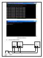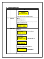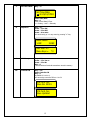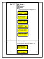
1
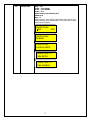
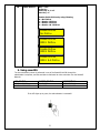
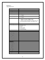
SmartXS Installation Guide
SmartXS
Firmware Ver. 3.9L
Model: SM212 Series
Release date: 01/11/2008
WARNING & CAUTION .................................................................................................... 2
Important Instructions : ....................................................................................................... 2
1. Before you start with SmartXS .................................................................................... 4
1.1. Included items .............................................................................................................. 4
2
Power Supply Specification:......................................................................................... 4
3
Installing SmartXS........................................................................................................ 5
3.1
Wire Connection Diagram ...................................................................................... 5
3.2
Jumper Settings: ...................................................................................................... 7
3.3
Power connection .................................................................................................... 8
Cable Specs Recommended (14/36, 22 AWG): - ............................................................... 8
3.4
Connecting Wiegand compatible readers................................................................ 8
3.5
Connecting Electro Magnetic Lock/Strike Lock to SmartXS................................. 8
3.6
Connecting to the Host computer............................................................................ 8
3.6.1
Connecting via RS-232 interface ........................................................................ 9
3.6.2
Connecting via RS-485 interface 2 wires............................................................ 9
3.6.3
Connecting via TCP/IP Using smartSERVER (RS485 to TCP/IP Converter.) .. 9
3.7
Fire Input Connection Details: .............................................................................. 12
4
Configuring smartXS.................................................................................................. 13
5. Using smartXS. ............................................................................................................ 21
Annexure: 1 ....................................................................................................................... 23
Annexure: 2 ....................................................................................................................... 24
1
WARNING & CAUTION
Ø Do not open system or place it near other heavy electrical equipments. The system is
sensitive to Electro Static Discharge (ESD)
Ø Please handle the equipment with care. Physical Damage to the system is not covered
under warranty.
Ø Do not power on the system without reading this manual. Ensure proper power supply
with Earthing.
Ø Note down the serial number and model no. of the device for future reference and quote in
all support and service requests.
Ø To connect or interface the Card reader to the SmartXS unit please refer to the Hardware
Installation Guide or Manual and carefully follow the instructions. A trained technician
must make the connections.
Any negligence on your part may damage the Card reader interface on the SmartXS
terminal.
Ø Mounting the unit in strong sunlight may affect user visibility of the LCD. Ensure that the
LCD and LED’s are clearly visible in all lighting conditions.
Ø The fingerprint sensor glass may periodically require cleaning - use suitable glass cleaner.
Ø Do not use this unit near water.
Ø Never insert objects of any kind into the unit or through the cabinet slots as they may
touch voltage points and/or short circuit parts possibly resulting in fire or electric shock.
Never spill liquid of any kind on the unit.
Ø when connecting up the Biometric Access Controller ensure that the mains power supply is
safely isolated. Power up the controller only when installation is complete.
Important Instructions :
1. Take the backup of the finger prints of all the users after enrollment, through the
Template Upload/Download Option in the Download Engine (Refer User Manual of
Download Engine for taking finger prints backup and uploading the backup finger
prints back to the Biometric devices.)
2. Care should be taken identifying the wires. Improper wiring may render permanent
damage to the device or personal injury.
3. In Single door controller do not connect lock on CH2 DOOR2.
4. Refer the color code on the Reader to connect the external weigand reader on the
controller.
5. Check the earthing at the site before installing the controllers. Normally the earthing
should be between 1V to 2V only. Earthing on the higher side may damage the
controller or its various other components.
2
3
1.
Before you
1.1. Included items
start with SmartXS
A SmartXS unit
Isolated Dual Power supply 12 V 1A & 12 V 1.2A
This Installation Guide
Product
Image
Qty
SmartXS
1
Access control or Attendance
System
Power Supply
1
Supplying power for
the Biometric Unit
1
For Device
Configuration/Management &
For Data Downloading
Software CD
User Manual & Test
Report
2
Use
1
For referring functions keys for
programming the device by
keypad
Power Supply Specification:
In case you do not have the required power supply included in the package and intend to buy your own
power supply use these specifications. Below given specifications should be strictly adhered to.
Device
Application
Power Supply
Input
Output
SmartXS
Attendance &
Access (Lock
Voltage)
Universal AC
Adapter Isolated
i/o
110 to 230
VAC
12 V DC/ 1A
(Min)
&
12 V DC/
1.2A (Min)
4
3 Installing SmartXS
3.1
Wire Connection Diagram
Diagram 1> SmartXS Wire Connection Diagram PCB version 1.3
2 readers as IN with 2 locks for 2 doors
5
Diagram 2> SmartXS Wire Connection Diagram PCB version 1.3
2 readers as IN & OUT with one locks for one doors
6
3.2
Jumper Settings:
485/232
PC Interface 485 Selection
232/485
selection
Default
JP13
485/232
PC Interface 232 Selection
JP13
JP9
EML/ Strike
Latch
selection for
1st Lock
Strike Latch Selection
EML
Strike
Latch
JP9
EML Selection
Strike
Latch
EML
Default
JP10
EML/ Strike
Latch
selection for
2nd Lock
12V /
Potential
Free o/p
selection for
Lock 1
EML
Strike
Latch
JP10
EML
Strike
Latch
12V
PF
EML Selection
12V output Selection
Default
Default
JP17 JP16
12V
PF
JP17 JP16
12V /
Potential
Free o/p
selection for
Lock 2
Strike Latch Selection
12V
PF
Potential Free output
Selection
12V output Selection
JP19 JP18
12V
PF
JP19 JP18
Potential Free output
Selection
7
Default
3.3
Power connection
Connect Red Wire (+ve) to 12+ and Black wire (Digital Ground) to G of the Power Adapter to connect
SmartXS to a DC supply (Power Adapter Supplied with the unit rated at 12V, 1A). While using as an
access controller, dual (10V-12V) power supply should be used. Connect the other pair of
wires to 12L and GL of dual power supply. The power cable should be as short as possible to
minimize wire resistance and emissions. (Refer the Cable Specs)
For optimum ESD resistance and safety, please make proper connection of ‘Earth GND’.
Cable Specs Recommended (14/36, 22 AWG): -
1. RS485 - Single unit to PC
Distance
1200m
2.RS232
15 m
3.Unit to Weigand Reader
80m
4. Egress/Exit
5. Magnetic Contacts
6. Unit to Magnetic Lock
7.Unit to Power supply
8. TCP/IP
10 ft. max
10ft. max
10 ft. max
10 ft max
100 m
Cable Specs
14/36, 22AWG; 2 core shielded
cable
14/36, 22AWG; 3 core shielded
cable
14/36, 22AWG; 6 Core Shielded
Cable
7/38, 26AWG; 2 Core Cable
7/38, 26AWG; 2 Core Cable
14/36, 22AWG; 2 Core Cable
14/36
CAT5 or CAT6 UTP
3.4
Connecting Wiegand compatible readers.
The SmartXS supports Wiegand compatible readers of various formats, viz 26/32/34/35 (HID corporate
1000 format)-bits.
Connect the external Weigand reader to READER2 connector on the controller. READER1 connector
on the controller is used for connecting the IN or 2nd Weigand reader.
Refer the color code of the Reader to connect the external weigand reader on the controller.
3.5
Connecting Electro Magnetic Lock/Strike Lock to SmartXS.
The SmartXS can be connected to Electro Magnetic Lock through DOOR1 connector pins. Connect 2 coreshielded cables on L+ and L- to Lock’s 12V and GND respectively. (Refer connection Diagram) for
connecting EML. The Strike Lock can also be connected to SmartXS by changing the jumper setting at
JP9 and JP10 Refer Jumper Setting table. On page no. table no.
3.6
Connecting to the Host computer
The SmartXS provides various means to connect to the host computer such as:
1. Being a part of the RS-485 network,
2. Direct connection with RS-232 interface
8
3.6.1 Connecting via RS-232 interface
Connect ‘RX’, ‘TX’ and ‘GND’ wires (LABELED CN1 232) on the controller to ‘TX’, ‘RX’ and signal
ground of PC’s serial port through DB9 connector. PIN NO 2,3,5 respectively
3.6.2 Connecting via RS-485 interface 2 wires
SmartXS network system For RS485 network, a two core shielded cable is needed. For every
devices, Connect ‘D+’ & D- to D+ & D- of the second device with which it is to be looped in a
network of RS485. At each end of the network, i.e from the last device the two wires from D+
and D- will be connected to TX+ & TX- of the RS232/RS485 Converter. The RS232 cable of
converter is connected to the serial port of the PC where the data is to be downloaded.
Figure 2> SmartXS RS485 Network
3.6.3 Connecting via TCP/IP Using smartSERVER (RS485 to TCP/IP Converter.)
The SmartXS series (SM212) can be connected on the LOCAL AREA NETWORK (LAN) using
smartSERVER as under:
NOTE : Max numbers of controllers on smartSERVER that can be connected are 10
numbers.
9
Straight network cable to connect from a hub or switch to the Biometric network
port.
Connecting Directly to a PC Using Crossover Network Cable
Step 1 Use the crossover network cable, with one end connected to the
smartSERVER’s TCP/IP port, and the other end to your PC network adapter.
10
Step 2 To check your PC’s IP Address Settings, find out the IP address of the network. To do so,
go to a PC in the network presently, press Start -> Run -> Type “command” and click on ‘OK’.
Step 3 Type “ipconfig” and press ‘Enter’.
Step 4 Note the IP Address displayed, following is an example.
Step 5 To Check the IP Address of biometric press *2 enter user id (11111) then # Enter
Password (12345) Key – # which will display the Current IP Address to Biometric, make a note of
it. (Default IP of the controller is 192.168.000.200)
Step 6 To change the IP Address in Biometric unit. Refer Configuration of SmartXS (port is
default 01234 no need to change)
Testing the Connection
Once the configuration is complete, it is recommended that the connection be tested.
To test the connection following is the under mentioned steps
Step 1 At the PC, Click Start -> Run -> Type “command” and press ‘OK’.
Step 2 Type “Ping 192.168.0.251 -t” (The IP Address should reflect that of your SmartXS unit)
Note: - If unsuccessful, either “Destination Host Unreachable” or “Request Timed Out” will be
displayed, please follow the above steps carefully and test the connection
11
Successful Connectivity
Unsuccessful connectivity
3.7
Fire Input Connection Details:
Unit No 1
GL FIRE
Unit No 2
GL FIRE
GL FIRE
GND
+12V
12V, 1A
External
Power
Supply
FIRE
Alarm-NO
Contact
Unit No N
12
4 Configuring smartXS.
Sr. No.
1.
Function
Normal mode
How to go?
Key – *0
Note & LCD Display
Welcome
17:23 27/10/07SA
In this mode card is shown and finger is verified.
2.
Change PIN
Key - *1
Enter card No. & press #
Enter Old PIN & press #
Enter New PIN & press #
If user added using *3 or *98 menu then last 4 digit number will
be the Pin number for that user.
Change Pin:
User ID: 00000
3.
Admin Mode
Key – *2
Enter User
Admin User:
User Id: 11111
Then Press Key - #
Enter Password
Admin User:
Password: 12345
Then press Key – #
Admin User:
Admin Login OK
To come out from Admin mode press Key – *2
Enter to Log out
(Auto logoff after 60sec)
13
Then press Key #
4.
Add User
Key – *3
Show card/ Enter UID
Key – #
Place figure
After showing card to unit. Will appear directly granted.
Add User:
User Id: 0000012345
Add Card:
Card Added_
5.
Delete User
Key – *4
Show card
Del User:
UID: 0000012345
Key – #
After entering UID or showing card, Press #. Then that user
gets deleted.
Del Card:
Card Deleted
6.
Search User
Key – *5
Show card
Key – #
If user is added then it will show card no.
Search User:
UserID: 12345
Search User:
0000012345L02345
14
7.
Set Time & Date
Key – *6
Set Time Date:
09:10 29/10/07MO
Enter Time/Date
Key – #
Enter correct Date & Time.
1 = Sunday,.. and 7 = Saturday
8.
Help Menu
Key – *8
Press – 1 for INC
Press – 3 for DEC
Press – # to enter
We can directly go in to any menu by pressing “#” key.
HELP MENU
1.INC
3.DEC
Add User: 03
Menu Keys =
9.
10.
*3
Initialize system
Key – *90
Press – 1 for Yes or
Press – 3 for No
Key – #
This will delete all cards & transactions stored in memory.
Controller ID
Key – *91
Enter Controller ID
Key – #
By default it is set to 1.
We can assign controller ID from 1 to 64.
ACS Cont. No:
Slave No: 00001
ACS Cont. No:
Slave Updated
15
11.
Add / Change or
Delete Admin
Users
Key – *92
Press – 1 for Add/Ch
Press – 3 for Del
Key – #
Enter user id then #
Enter password
Key – #
We can add max 8 admin users including default user.
Add Admin Id:
1:Add/Ch
3:Del
Add Admin User:
User ID: 12345
Add Admin User:
NewPass: 12345
Add Admin Id:
1:Add/Ch
3:Del
Admin User Added:
ID: 12345 L00002
Admin User Added:
ID: 12345 L00002
12.
Door open time
Key – *95
Enter door open time
Key – #
Door open time can be set 1 to 99 secs.
And DOTL sense time is equal to Door open time + 1 sec.
Door OpenTime:
Door Time:00005
Door OpenTime:
Door Time Saved
16
13.
Facility code
Key – *96
Press – 1 for Enable
Press – 3 for Disable
Press – # #
Enter Facility code location (0-7)
Show card
Key – #
After pressing 1, Enter facility code location & show card. Then
facility code will come automatically for that card. Max 8 facility
codes can be assigned.
Facility Code:
1:EN
3:DI
Facility Code:
Enabled
Facility Code:
Location:00001
Facility Code: 01
Code:00255
Facility Code: 01
Code Updated
17
14.
Add Card Data
Key - *98
Assign access type to the card. Press Key0 = Card Only
2 = Card/UID Only
4 = (UID/Card) + PIN
6 = Card + PIN
Key – #
It is required to Enable PIN for readers (using *997) otherwise
‘UID/(Card+PIN)’ type will work as ‘Card/UID only’ & ‘Card+PIN’
type will work as ‘Card only’
Also it is required to enable Keypad from Software to enable UID
from keypad.
Users can be added by *98 menu also.
Add Card Data:
User ID: 12345
00000
Add Card Data: 06
Card Only
Add Card Data: 02
Card/UID Only
Add Card Data: 10
(UID/Card) + PIN
Add Card Data: 14
Card + PIN
15.
Weigand Bit
NA
18
16.
Reader Type
Key – *991
Press Key – 0 to 6
Key – #
Controller type can be set by pressing0 = Weigand access
1 = Weigand access 2 RD
2 = Weigand attendance
3 = Weigand attendance 2 RD
4 = Weigand attendance no
check
5 = Weigand attendance no
check for 2 RD
6 = Deny List
Reader Type
Wei Access
Reader Type
Wei Access 2 DR
Reader Type
Wei Att
Reader Type
Wei Att 2 DR
Reader Type:
Wei Att . NoChk
Reader Type:
Wei Att . NoChk 2D
Reader Type:
Deny List
19
17.
Baud rate
Key – *992
Key – #
Baud rates is,
9600b/s (Default)
Baud Rate:
Baud Rate: 9600
18.
Reader In-Out
Key – *993
Press Key
0 for Normal
1 for IN
2 for OUT
Key – #
Standalone Reader type can be set as,
You can toggle in between In & Out Entry by pressing 0 key.
Reader In/Out:
Reader Normal
Reader In/Out:
Reader In
Reader In/Out:
Reader Out
19.
Set 5/10 Digit
card no format
Key – *995
Press – 5 for 5-Digit
Key – #
5 Digit Card
Press – Any Num Key except 5 for 10-Digit
Key – #
10 Digit Card
20
20.
Enable PinProx
Key – *997
Press Key
Enter Key- 0, 1 or 3
then Key – #
Enable disable PinProx by using following
0 = No PinProx
1 = Reader 1 PinProx
2 = Reader 2 PinProx
3 = Reader 1 & 2 PinProx
Enable PinProx
No PinProx
Enable PinProx
RDR 1 PinProx
Enable PinProx
RDR 2 PinProx
Enable PinProx
RDR 1 & 2 PinProx
5. Using smartXS.
The user enrollment process is performed in one of the SmartXS Unit OR through the
administrator’s computer, and the card data is distributed to other controllers over the SmartXS
Network.
LED STATUS
BUZZER STATUS
DESCRIPTION
LED FLASHES RED
LED FLASHSES GREEN
SHORT BEEP
LONG BEEP
USER NOT FOUND
ACCESS GRANTED
If the LED lights up in green, the authentication is successful.
21
Trouble Shooting
# 1. No Communication from smartXS Controller to PC
There are a few points that can be checked to fix it:
1) Make sure the network cable is functional; sometimes a damaged cable may be the cause of
all problems. To check if it is functional, make sure there are no loose ends and the jack is
properly attached to the cable.
2) Check that the IP Address Assignment matches the network settings of the corporate LAN or
the PC being used.
3) Make sure no IP has clashed and that there are no two identical IP addresses in the network.
# 2. LCD screen of the smartXS completely blank
i. Check whether the power supply is working or not
ii. The output vtg generated by the power supply is 12V DC Check this vtg using multimeter if
possible.
iii. Check 12V-G-12L-GL-power connector properly inserted into a socket.
# 3. Is it possible to connect two locks or two readers on single connector?
Do not connect 2 locks or 2 readers together on a single connector. A single lock connector can
safely drive 600mA current.
If load current increases beyond 1A, that may cause hardware problems.
# 4. LCD backlight is on but characters are not display or light display
Check the output vtg by the power supply is 12V-GND connector.
Biometric is provided with blue color pot, which is easily accessible from backside window of the
unit.
Rotate the pot slowly using small flat screw driver in clockwise/anticlockwise direction and keep
on checking the intensity of the LCD backlight, you can keep the intensity according to your
requirement.
# 5. When the card is flashed in display its show “user not found”
To Enter into Admin Mode Refer Configuring SmartXS Serial No.2
Check for controller Key – *5
Show card
Key – #
If user is added then it will show card no enrolled.
# 6. Continues Beep & Door Force Open
Check for lock magnetic contact (MC+/ MC-), it should be short if not in used.(Refer connection
Diagram)
# 7. Admin User: User/Password Fail
If the System/Unit is initialize then password will not match. In this case RESET the System i.e
power off and then power on the system then enter Admin Id and password.
22
Annexure: 1
*90 Selective Initialization of System
00 Delete all data
Every Info is deleted and set to default value
01 Delete Transaction
02 Delete All Users
All transaction are deleted
All users i.e. card buffer are deleted
03 Set All Default
Deletes all info and set it to default value, except cards
buffer and transactions
Deletes current system parameter and set all with
default system parameter
Deletes all time zones and set default time zone
Deletes all holidays
04 Delete Sys. Info
05 Delete Time Zone
06 Delete Holiday
07 Delete Facility Code
08 Delete Door info
09 Delete Admin IDs
10 Reset System
11 Delete Cards Only
Facility codes are deleted and all are set to default
Facility code
Deletes door information and set to default Door
information
Admin Id is deleted and set to default ID
Resets the system
Only card buffer is deleted
23
Annexure: 2
*991 System parameter
Terminal ID
IP Address
Net Mask
Gateway
Server IP
Port Number
Global Message
1-32 controller ID
0- Disable
1- Enable
0- Disable
1- Enable
0- No inout selection
1- Reader in In mode (Toggle by 0 key)
2- Reader in out mode (Toggle by 0 key)
3- Reader in Mode and will go for out mode when zero
key is pressed and will remain in out mode for 5 sec
Banner Message
Cont InOut
IdentifyMode
Controller Type
User Name Loc.
Memory Mgmt
Last Card Time
Inout TimeZoneX
IN Out For TZX
InOut Toggle
DummyMode
Check Pin
Freetimeenable
Freetimedoor1
Freetimedoor2
Exshardotl
APBENABLE
FaclityCode_Chk
Pineable_Door1
Pineable_Door2
Exdotl_dly1
Exdotl_dly2
Exdop_tim2
Pc_door1_open
Pc_door2_open
Extdotl1_En
Extdotl2_En
Exdop_Tim1
Exdop_Tim2
NA
0=
1=
2=
3=
4=
5=
Bio Access
Bio Access 2 DR
Bio Att.
Bio Att. 2 DR
Bio Att.NoChk
Bio.Att.NoChk2DR
NA
24
Dummy Mode
UDP IP Address
UDP Port No.
Push SRV IP 1
Push SRV IP 2
Input Enadis
DummyMode
User name location
Memory Management
Last card time
Input EnaDis
0- No name display
1- Name displayed from Unit
2- Name displayed from Smart card
00- Do not display any memory data and allow memory
to overwrite
>100-(Less than 100 & not
equal 0) Display memory
data in % and Allow memory over write after 100%
>=100-(greater than or equal)
Do not allow memory over write and display memory
data in %
0 – Disable i.e. do not check same card
Or
Display Time set in seconds
0 Disable
1 Enable
25