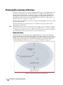
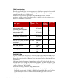
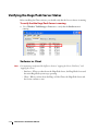
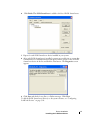
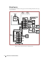
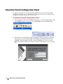
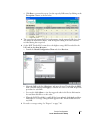
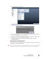
1
Infrastructure
Installation
Manual
for
Hugs and Pedz
Xmark Corporation
309 Legget Drive
Ottawa, ON K2K 3A3
Canada
Telephone: 1.86655.XMARK
International: +1 (613) 592.6997
Facsimile: (613) 592.4296
Web site: www.xmark.com
E-mail: [email protected]
Certified to the ISO 9001 Quality Standard
© 2008 Xmark Corporation. All Rights Reserved. Printed in Canada. 981-000316-000 Rev 02. November 2008.
Hugs software release 5.54.
Warranty
Xmark’s products are warranted against defects in materials and workmanship and shall perform in accordance
with published specifications for a period of one year.
Xmark's warranty is limited solely to the repair or replacement of the defective part or product. Xmark reserves the
right to change product specifications without notice.
Limitation of Liability
This Product has been designed for use to assist in the prevention of infant or pediatrics abduction and/or mother/
infant mismatching.
The range, accuracy, function and performance of this Product may vary from the published specifications due to
many factors, including, without limitation, site impairments from structural effects, metal objects in the vicinity,
placement of the receiver and transmitter, interference from other electrical devices, atmospheric effects,
installation, and maintenance. There may be other factors, which also affect performance of this Product.
Xmark Corporation does not guarantee that this Product will detect 100% of infant or pediatrics abductions and/
or mother/infant mismatches. Xmark does not guarantee that this Product will not return false reports of infant or
pediatrics abductions and/or mother/infant mismatches.
Monthly testing and maintenance of this Product, as described in the Product documentation, is essential to verify
the system is operating correctly and to ensure that the probability of detecting an alarm and/or locating the
transmitter are maximized.
The failure to undertake regular testing and maintenance will increase the risk of system failure and failure to detect
infant or pediatrics abductions and/or mother/infant mismatches. The failure to undertake regular testing and
maintenance will increase the risk of false reports of infant or pediatrics abductions and/or mother/infant
mismatches.
Xmark hereby disclaims all warranties, express or implied, arising out of or in connection with any of its Products
of the use or performance thereof, including but not limited to, where allowable by law, all other implied
warranties or conditions of merchantable quality and fitness for a particular purpose and those arising by statute or
otherwise in law or from a course of dealing or usage of trade.
Xmark hereby disclaims all warranties, express or implied, arising out of or in connection with any of its
Products of the use or performance thereof, including but not limited to, where allowable by law, all other
implied warranties or conditions of merchantable quality and fitness for a particular purpose and those arising
by statute or otherwise in law or from a course of dealing or usage of trade.
Xmark’s liability to you or anyone claiming through or on behalf of you with respect to any claim or loss arising
out of the use or misuse of Xmark’s Product, defective products or materials, improper installation or
maintenance of Xmark's Product or products or the system in which they are incorporated, or alleged to have
resulted from an act or omission of Xmark or any person, negligent or otherwise, shall be limited to:
(a)
the repair or replacement of defective Product or materials supplied by Xmark during the warranty
period as set out in the Product documentation; or, at the option of Xmark,
(b) a refund of the purchase price of the Product supplied by Xmark.
In no event shall Xmark be liable for general, specific, indirect, consequential, incidental, exemplary or punitive
damages or any losses or expenses suffered by you or anyone else, whether or not Xmark, or its employees,
officers, agents, resellers or installers has been informed of the risk of such loss or expense and whether or not
such losses or expenses were foreseeable.
Cell Phones and the Hugs or Pedz System
The 217 MHz frequency (434 MHz for international sites) of the Hugs or Pedz system was specifically chosen
because cellular phones and pagers, among other devices, do not operate in this frequency range and should not
interfere with the operation of the Hugs or Pedz system. The receivers in the Hugs or Pedz system were designed
with filters to reject interference.
Magnetic Resonance Imaging (MRI)
Since the tags contain metal components, they must be removed before a patient undergoes an MRI scan.
Ultraviolet (UV) Light
Because the tag is made of an ABS plastic, it is not as susceptible to UV light as other plastics such as poly
carbonate materials. Minor impacts or label ink and plastic discoloration, can be avoided by regular tag rotation
to ensure that the same tags are not continually exposed to UV light. A crack appearing on the tag’s surface should
be noticed immediately by staff, eliminating any chance of reducing the integrity of the infant security system.
UL Listing
This system is listed as an Access Control System by Underwriters Laboratories Inc., Standard for Safety. The
Access Control System listing is valid when all computers and displays in the Hugs/Pedz system are listed to UL
under the UOXX2 category.
The following components have not been evaluated as part of the Access Control System listing: computer
speakers, all LonWorks® network accessories.
Warnings
Please observe the following warnings when using the Hugs or Pedz system.
• Wire mesh can severely affect the operation of the Hugs or Pedz system - wire mesh, foil-backed ceiling tiles, and
other metal barriers in walls and ceilings interfere with radio frequency transmission and reception. The Hugs or
Pedz system may not operate properly in facilities where these materials are used.
• Patients will not be protected in the event of a general power failure -The Hugs or Pedz system does not
incorporate an emergency power supply circuit.
Tags
• No user adjustments - Tampering with the internal circuitry may cause component or system failure, or both,
and will void the warranty.
• Battery handling - the tags contain a lithium battery. Do not force open, heat to 100° C, or dispose of in fire.
• X-rays - do not directly expose the tag to X-rays. (The tag is not affected by stray radiation.)
Local Area Receiver
• Electrostatic discharge could damage the Local Area Receiver and transceiver and internal components - touch
your hand to ground to discharge any electrostatic charge before wiring the LAR.
• No user adjustments -Tampering with the internal circuitry may cause component or system failure, or both,
and will void the warranty.
• Follow installation instructions precisely - instructions must be carefully followed throughout the installation of
all Local Area Receivers. Failure to follow the instructions may cause degraded performance.
Exciter and Range Extender
• Electrostatic discharge could damage the Exciter’s internal components - touch your hand to ground to
discharge any electrostatic charge before wiring the Exciter.
• No user adjustments -Tampering with the internal circuitry may cause component or system failure, or both,
and will void the warranty.
• Follow installation instructions precisely - instructions must be carefully followed throughout the installation of
all Exciters. Failure to follow the instructions may cause degraded performance.
• The Exciter is not UL listed as elevator equipment -The fire control panel shall override the Exciter when the
latter is wired to an elevator control system.
• Ensure that the fire control panel has control over all magnetic door locks interfaced to the Exciter. Install door
locks in fail-safe mode so that they release upon loss of power or loss of connection to the fire control panel.
Hugs/Pedz Server
• Do not operate other software programs at the same time as the Hugs or Pedz software - do not use these or
other software:
1
Disk compression - do not use compressed disk drives. Drive compression technology is not recommended.
2
Back up programs - back up programs, including the Microsoft® Windows® back up program, warn of
problems when continuing to use the system during a backup. Also, the system does not support the use of
a tape drive. Exit the Hugs/Pedz Server software before starting a back up session.
• Turn off power management for all computers used in the Hugs or Pedz system—power management can
interfere with the proper operation of the Hugs or Pedz system software.
Statements
The following statements apply to the Hugs tag, Kisses tag, Pedz tag, Local Area Receiver, Exciter, and Range
Extender.
United States—Federal Communication Commission (FCC)
This device complies with Part 15 of the FCC Rules. Operation is subject to the following two conditions: (1) this
device may not cause harmful interference, and (2) this device must accept any interference received, including
interference that may cause undesired operation.
Note: This equipment has been tested and found to comply with the limits for a Class A digital device, pursuant to
Part 15 of the FCC Rules. These limits are designed to provide reasonable protection against harmful interference
when the equipment is operated in a commercial environment. This equipment generates, uses, and can radiate
radio frequency energy and, if not installed and used in accordance with the instruction manual, may cause harmful
interference to radio communications. Operation of this equipment in a residential area is likely to cause harmful
interference in which case the user will be required to correct the interference at his own expense.
Warning: Changes or modifications not expressly approved by Xmark could void the user’s authority to operate
the equipment.
Canada—Industry Canada
This device complies with RSS-210 of Industry and Science Canada. Operation is subject to the following two
conditions: (1) this device may not cause interference, and (2) this device must accept any interference, including
interference that may cause undesired operation of the device.
European Union
The following statements apply to the international Hugs tag, Kisses tag, Local Area Receiver, Exciter, and Range
Extender.
CE declaration
Xmark hereby declares that this radio frequency device is in compliance with the essential requirements and other
relevant provisions of Directive 1999/5/EC.
TABLE OF CONTENTS
CHAPTER 0
List of Procedures........................................................................ xi
Introduction..............................................................................1-1
About this Manual................................................................................................. 1-1
Audience ............................................................................................................... 1-1
Reference Materials................................................................................................ 1-1
Infrastructure Components.................................................................................... 1-2
Local Area Receivers................................. .................................................................................1-2
Exciters and Range Extenders................... .................................................................................1-3
Hugs/Pedz Server ..................................... .................................................................................1-4
Hugs/Pedz Client PC ............................... .................................................................................1-4
Interface Devices ...................................... .................................................................................1-5
Tags ....................................................................................................................... 1-7
Hugs Tag.................................................. .................................................................................1-7
Kisses Tag................................................. .................................................................................1-8
Pedz Tag................................................... .................................................................................1-9
System Design...........................................................................2-1
Hugs/Pedz System Overview ................................................................................. 2-2
About Radio Frequency ......................................................................................... 2-3
Assessing the Facility.............................................................................................. 2-4
General Considerations for designing a Pedz system...................................................................2-7
Planning the Location of Exciters .......................................................................... 2-8
Detection Area ......................................... .................................................................................2-8
Installation Options ................................. ...............................................................................2-10
Using an Exciter as a Gateway .................. ...............................................................................2-12
Auto-Return Exciter Installations (Pedz)... ...............................................................................2-12
Access Group Considerations (Pedz) ........ ...............................................................................2-13
Location Considerations .......................... ...............................................................................2-13
Master/Slave Installations ......................... ...............................................................................2-13
Elevator Installations ................................ ...............................................................................2-17
Creating a LAR Coverage Plan ............................................................................ 2-19
LAR Detection Patterns ........................... ...............................................................................2-19
Location Considerations .......................... ...............................................................................2-20
Preliminary LAR Coverage Plan ............... ...............................................................................2-21
Example of LAR placement for specific locations .....................................................................2-22
Tag Locating........................................................................................................ 2-23
LonWorks Network Design ................................................................................. 2-24
Communication Cable............................. ...............................................................................2-24
Topology and Termination....................... ...............................................................................2-25
Power Cable ............................................. ...............................................................................2-30
vii
Hugs/Pedz Server & Client PC Installation .............................. 3-1
System Requirements............................................................................................. 3-2
LAN Requirements................................................................................................ 3-3
Installing Internet Information Services (IIS)......................................................... 3-5
Installing Internet Explorer....................... ................................................................................ 3-8
Installing Microsoft Office Web Components ........................................................................... 3-8
Installing the Hugs/Pedz Server ............................................................................. 3-8
Installation Considerations....................... ................................................................................ 3-8
Tools and Materials Required ................... ................................................................................ 3-9
Installing the Watchdog Card (Hugs Only) ............................................................................... 3-9
Installing System Software Components .............................................................. 3-13
Important Notes about Upgrading ........... .............................................................................. 3-13
Installing SQL Server Express................... .............................................................................. 3-17
Installing LonWorks Software................... .............................................................................. 3-19
Xmark Reports ......................................... .............................................................................. 3-21
Installing Xmark Server Software.............. .............................................................................. 3-26
Installing Client Software .................................................................................... 3-31
Verifying the Hugs/Pedz Server Status.................................................................. 3-36
XmServer vs. Client.................................. .............................................................................. 3-36
Connected Clients ............................................................................................... 3-37
Installing the Xmark License................................................................................ 3-38
LapLink (Hugs) ................................................................................................... 3-40
Touch Screen Option .......................................................................................... 3-45
Stopping the Xmark Service................................................................................. 3-46
Device Installation .................................................................... 4-1
Installing the Central Power Supply (CPS) ............................................................ 4-2
Tools and Materials Required ................... ................................................................................ 4-2
Installation ............................................... ................................................................................ 4-2
Installing the iLON SmartServer ........................................................................... 4-4
Setting the iLON SmartServer IP Address ................................................................................ 4-4
Configuring the iLON SmartServer ......... ................................................................................ 4-6
Installing Local Area Receivers (LARs)................................................................. 4-10
Installation Tips ....................................... .............................................................................. 4-10
Tools and Materials Required ................... .............................................................................. 4-11
Installation ............................................... .............................................................................. 4-11
Testing the LAR Installation Environment .............................................................................. 4-14
Installing Exciters and Range Extenders............................................................... 4-15
Installation Tips ....................................... .............................................................................. 4-15
Tools and Materials Required ................... .............................................................................. 4-15
Installation ............................................... .............................................................................. 4-16
Installation of Optional Equipment.......... .............................................................................. 4-18
Master/Slave Installations ......................... .............................................................................. 4-20
Wiring Diagrams...................................... .............................................................................. 4-22
viii
Infrastructure Installation Manual
Installing I/O Modules ........................................................................................ 4-23
Installation Tips ....................................... ...............................................................................4-23
Tools and Materials Required ................... ...............................................................................4-23
Installation ............................................... ...............................................................................4-24
Installing the PCLTA- 21 PCI Hardware ............................................................. 4-26
Installing the Network Repeater .......................................................................... 4-26
Device Configuration................................................................5-1
About the Xmark Configuration Client ................................................................. 5-2
Creating Zones (optional)...................................................................................... 5-5
Adding Facility Maps............................................................................................. 5-8
Server Information ................................................................................................ 5-9
Settings and Command Buttons............... .................................................................................5-9
Configuring LonWorks Devices........................................................................... 5-10
Settings and Command Buttons............... ...............................................................................5-10
Adding Icons to Maps .............................. ...............................................................................5-13
LNS Device Credits ................................. ...............................................................................5-15
Local Area Receiver Setup.................................................................................... 5-18
LAR Settings and Command Buttons ...... ...............................................................................5-18
Exciter/Range Extender Setup ............................................................................. 5-22
Exciter/Range Extender Settings and Command Buttons.........................................................5-22
Configuring Exciters/Range Extenders ..... ...............................................................................5-23
Configuring Exciter/Range Extender Relays .............................................................................5-26
Master/Slave Configurations .................... ...............................................................................5-29
I/O Module Setup ............................................................................................... 5-30
I/O Settings and Command Buttons........ ...............................................................................5-30
Configuring I/O Modules ........................ ...............................................................................5-31
Advanced LonWorks Device Configuration......................................................... 5-38
Downloading firmware ............................ ...............................................................................5-38
Download Neuron Command ................. ...............................................................................5-40
Configuring Pedz Features ................................................................................... 5-42
User-Defined Fields.................................. ...............................................................................5-42
Access Groups .......................................... ...............................................................................5-44
Tag Ranges............................................... ...............................................................................5-46
Configuring Hugs Features .................................................................................. 5-47
Deterministic BabySense .......................... ...............................................................................5-47
Require Zone on Admit ........................... ...............................................................................5-49
Optional Devices ......................................................................6-1
Paging Systems ...................................................................................................... 6-2
Paging System Setup ................................ .................................................................................6-2
Integrated CCTV Option...................................................................................... 6-5
Installation Options ................................. .................................................................................6-5
ix
Installation ............................................... ................................................................................ 6-7
Setup in the System Software.................... ................................................................................ 6-9
Access Card Reader Option ................................................................................. 6-12
System Verification ................................................................... 7-1
Verifying Local Area Receivers ............................................................................... 7-2
Tools and Materials Required ................... ................................................................................ 7-2
How System Verification Works ............... ................................................................................ 7-2
Adjusting a Local Area Receiver................ ................................................................................ 7-4
Verifying Exciter/Range Extenders ......................................................................... 7-8
Tools and Materials Required ................... ................................................................................ 7-8
Testing Doorway Coverage....................... ................................................................................ 7-8
Testing Nuisance Alarm Distance ............. ................................................................................ 7-9
Testing Door Contacts and Relays............ ................................................................................ 7-9
Field Strength Adjustment........................ ................................................................................ 7-9
Checking an Exciter/Range Extender’s Operation.................................................................... 7-10
Verifying I/O Modules......................................................................................... 7-12
Tag Diagnostics ................................................................................................... 7-12
Interpreting Results .................................. .............................................................................. 7-14
Transmit Error Rates............................................................................................ 7-14
Checking the Wiring................................ .............................................................................. 7-15
Verifying LonWorks Device Count Statistics ........................................................................... 7-15
Tag Message Rates ............................................................................................... 7-16
Final System Check ............................................................................................. 7-17
Reports..................................................... .............................................................................. 7-20
General System Review ............................ .............................................................................. 7-23
Backing Up Essential System Files ....................................................................... 7-24
Automatic Backup of Database Records ... .............................................................................. 7-24
Backup and Disaster Recovery Procedure . .............................................................................. 7-25
Important Note about Auto-Discharged Tags ...................................................... 7-26
System Audit ............................................ .............................................................................. 7-26
About the Xchange Knowledgebase ..................................................................... 7-26
Accessing Xchange.................................... .............................................................................. 7-26
Alarm Quick Reference.............................................................A-1
Device Specifications ................................................................B-1
PCLTA-21 Card .......................................................................C-1
Installing the LonWorks Card................................................................................C-2
Configuring the LonWorks Card ...........................................................................C-2
NSS Registration Utility ........................................................................................C-3
x
Infrastructure Installation Manual
LonWorks Network Repeater ................................................... C-1
Installing a LonWorks Network Repeater ..............................................................C-2
Installation Tips ....................................... ................................................................................C-2
Tools and Materials Required ................... ................................................................................C-2
Mechanical Installation ............................ ................................................................................C-2
Network Termination............................... ................................................................................C-2
Wiring the Network into the LonWorks Repeater .....................................................................C-3
Index......................................................................................... I-1
xi
xii
Infrastructure Installation Manual
LIST OF PROCEDURES
CHAPTER 0
Before testing for LF Noise (Kisses)........................................................................... 4-14
To access Xchange..................................................................................................... 7-26
To add another LAR ................................................................................................... 7-8
To add card access information manually to a user account....................................... 6-16
To add facility maps.................................................................................................... 5-8
To add icons to maps (for Hugs and Pedz)................................................................ 5-14
To add icons to maps (for Hugs only) ....................................................................... 5-13
To add LNS Device Credits ...................................................................................... 5-16
To assign a camera to an exciter ................................................................................ 6-11
To calculate the maximum Exciter run length for the given cable.............................. 2-32
To calculate the maximum LAR run length for the given cable ................................. 2-31
To calculate the total wiring resistance to all Exciters on the segment........................ 2-32
To calculate the total wiring resistance to all LARs on the segment ........................... 2-31
To check for metal objects .......................................................................................... 7-7
To check the noise environment for LAR.................................................................... 7-6
To check the physical installation of a LAR................................................................. 7-6
To configure Access Groups...................................................................................... 5-44
To configure devices and tags to send pages ................................................................ 6-4
To configure Exciters/Range Extenders ..................................................................... 5-24
To configure I/O module inputs ............................................................................... 5-33
To configure I/O module outputs ............................................................................. 5-36
To configure I/O Modules ........................................................................................ 5-32
To configure LapLink Program Options ................................................................... 3-44
To configure LARs.................................................................................................... 5-19
To configure LonWorks Devices............................................................................... 5-11
To configure Master/Slave settings ............................................................................ 5-29
To configure Modem Settings................................................................................... 3-43
To configure relays.................................................................................................... 5-28
To configure tag ranges ............................................................................................. 5-46
To configure the iLON SmartServer ........................................................................... 4-6
To configure the LonWorks card ................................................................................C-2
To configure the system software ................................................................................ 6-2
To connect the pager to the Hugs/Pedz Server ............................................................ 6-2
To create a preliminary LAR coverage plan ............................................................... 2-21
To create User Accounts ............................................................................................. 6-8
List of Procedures
xi
To create user-defined columns in the Census List .................................................... 5-42
To create Zones .......................................................................................................... 5-6
To customize Backup settings for your system........................................................... 7-24
To customize the window color .................................................................................. 5-4
To determine which PCs are connected .................................................................... 3-37
To download I/O module firmware .......................................................................... 5-39
To download Neuron types....................................................................................... 5-40
To enable CCTV ........................................................................................................ 6-9
To enable the Touch Screen Option ......................................................................... 3-45
To enter User Account information .......................................................................... 6-10
To install a new 5.54 system ..................................................................................... 3-16
To install CCTV on an existing LAN ......................................................................... 6-8
To install CCTV on the system LAN.......................................................................... 6-7
To install Exciters and Range Extenders .................................................................... 4-16
To install I/O Modules ............................................................................................. 4-24
To install IIS on Vista ................................................................................................. 3-6
To install IIS ............................................................................................................... 3-5
To install LapLink..................................................................................................... 3-40
To install LARs ......................................................................................................... 4-12
To install the Bar Code Reader ................................................................................. 6-15
To install the Client software .................................................................................... 3-31
To install the CPS....................................................................................................... 4-2
To install the iLON SmartServer device ...................................................................... 4-4
To install the LonWorks card......................................................................................C-2
To install the LonWorks software ............................................................................. 3-19
To install the Magnetic Stripe Card Reader............................................................... 6-12
To install the Network Repeater .................................................................................C-3
To install the Proximity Card Reader ........................................................................ 6-14
To install the SQL Server Express ............................................................................. 3-17
To install the Watchdog card .................................................................................... 3-10
To install the Xmark Server Software ........................................................................ 3-26
To install Xmark Reports .......................................................................................... 3-21
To launch the Client Application.............................................................................. 3-35
To launch the Xmark Configuration Client ................................................................ 5-2
To manually download LAR firmware ...................................................................... 5-38
To migrate from Hugs 5.42 to 5.54 (new PC) .......................................................... 3-15
To migrate from Hugs 5.42 to 5.54 (same PC)......................................................... 3-13
To perform a final Exciter coverage check (Hugs) ..................................................... 7-19
xii
Infrastructure Installation Manual
To perform a final Exciter coverage check (Pedz) ...................................................... 7-19
To perform a final LAR system check........................................................................ 7-17
To perform a Hugs 5.5 backup ................................................................................. 7-25
To Reposition the LAR ............................................................................................... 7-7
To reset Tag Low Battery information ...................................................................... 7-22
To Restore files ......................................................................................................... 7-25
To set RSSI thresholds .............................................................................................. 5-20
To set the Deterministic BabySense option ............................................................... 5-48
To set the iLON SmartServer IP address..................................................................... 4-5
To set the Zone selection option ............................................................................... 5-49
To setup a User Profile for Xmark............................................................................. 3-41
To start LapLink ....................................................................................................... 3-41
To stop the Xmark service......................................................................................... 3-46
To test doorway coverage ............................................................................................ 7-8
To test for LF noise at each location (Kisses)............................................................. 4-14
To test nuisance alarms ............................................................................................... 7-9
To update the Hugs/Pedz license .............................................................................. 3-38
To upgrade from Hugs 5.52 to 5.54 ......................................................................... 3-16
To verify LARs............................................................................................................ 7-3
To verify that the Hugs/Pedz Server is running ......................................................... 3-36
To verify transmit errors............................................................................................ 7-15
To view all alarms ..................................................................................................... 7-23
To view messages from one specific tag ..................................................................... 7-12
To view messages received by one specific LAR......................................................... 7-13
To view Reports ........................................................................................................ 7-20
To view tamper messages .......................................................................................... 7-13
List of Procedures
xiii
xiv
Infrastructure Installation Manual
Chapter
1
INTRODUCTION
CHAPTER 0
About this Manual
This manual provides instructions for installing, configuring, testing and troubleshooting
all the interrelated components (devices) for Xmark’s Hugs and Pedz infant/patient
protection systems.
Audience
This manual is intended for the trained installer who is familiar with wiring in
commercial and industrial facilities, micro-electronics including static-sensitive
components, and computers.
Reference Materials
The following reference materials may be used in conjunction with this manual:
• Hugs User Guide (805U1601)
•
Pedz User Guide (980-806001-000)
Introduction
About this Manual
1-1
Infrastructure Components
This section describes the following Hugs or Pedz infrastructure components:
• Local Area Receivers (LAR)
•
Exciters and Range Extenders
• Hugs/Pedz
•
Server and Client PCs
LonWorks Interface Devices
Local Area Receivers
Local Area Receivers (LARs) are radio frequency reception devices installed at regular
intervals throughout the monitored area of the facility. LARs receive the tag
transmissions, time stamp them, and relay them to the Hugs/Pedz Server via a LonWorks
network. LARs are installed in ceilings, usually out of view.
The Hugs/Pedz Server monitors the operation of each LAR to ensure a high level of
operational confidence. If the LAR fails to operate for any reason, an alarm occurs.
Figure 1.1 Local Area Receiver (LAR)
1-2
Infrastructure Installation Manual
Exciters and Range Extenders
Exciters monitor the exits from the protected area. Installed above or beside a doorway,
the Exciter emits a detection field that covers the opening. When a tag enters the field, it
immediately transmits a special message to the Hugs/Pedz Server via the LARs. In a
typical installation (with door contacts connected to the Exciter), an alarm only occurs if
the door is open, as the child is then at immediate risk of being removed without
authorization. Once an alarm does occur, an Exit Alarm message is automatically
generated at all PCs.
Each Exciter also includes two relays, which can be used to control a variety of devices
including magnetic door locks or high output alarms. Optional keypads may be
connected to enable staff to transport children/infants under local password control.
Exciters may also be placed strategically throughout the hospital to allow the progress of
an abduction or flight attempt to be monitored. For very large openings or areas, a Master
Exciter Range Extender can be used along with an Exciter to extend coverage. This device
is similar to an Exciter in appearance and functionality.
“Auto-Return” Exciters are installed just inside the protected area to automatically reenroll the child back into the system once they are returning from a Transport (Pedz).
Exciters are continually monitored by the Hugs/Pedz Server, and a warning message
automatically displays if there is a problem.
Xmark also offers the Range Extender. This device is used with an Exciter to extend
coverage to protect very large doorways that cannot be covered by a single Exciter. The
Range Extender’s design and functionality is similar to those of the Exciter, except that it
can only be used as a Slave (see “Master/Slave Installations” on page 4-20 for details).
Figure 1.2 Exciter
Introduction
Infrastructure Components
1-3
Hugs/Pedz Server
The Hugs/Pedz Server is a Microsoft Windows based computer running the system
software for the Hugs/Pedz application. It is connected to the network of Local Area
Receivers (LARs), Exciters, and I/O Modules, and monitors and controls all system
activity.
The system is fully supervised and the software can be configured to respond to system
events automatically. It can activate door locks, sounders or other equipment during an
alarm or when selected events occur.
The Hugs/Pedz Server automatically updates the status of all tags, and monitors the
operation of LARs, Exciters, Clients and other network devices. All activity, including
alarms, is recorded within a database. Reports can be viewed and printed. Custom reports
can be created by importing the database into third-party software programs such as
Excel.
Figure 1.3 Server or Client PC
Hugs/Pedz Client PC
The Hugs/Pedz Client is a Microsoft Windows based computer running the system
software for the Hugs/Pedz application. It is connected to the Hugs/Pedz Server over
the local area network (LAN), and enables users to monitor system activity and respond to
events.
The Hugs/Pedz Client receives all data on changes in patient status and other events from
the Hugs/Pedz Server in real time. Users at the Hugs/Pedz Client may clear alarms,
authorize transports and perform other basic tasks, provided they have password
clearance. These actions are recorded in the Hugs/Pedz Server database, and are
automatically relayed to all other Hugs/Pedz Clients.
The Hugs/Pedz Client uses the system software as the central user interface. Only taskcritical information is offered, through easy-to-understand dialog boxes. Configuration is
accessible from the Hugs/Pedz Client.
The Hugs/Pedz Server monitors the operation of the Hugs/Pedz Client, generating an
alarm if communication is lost.
1-4
Infrastructure Installation Manual
Interface Devices
Xmark uses the iLON SmartServer as the standard interface device to monitor and
control infrastructure networks and devices. For information about running the system
using an existing PCLTA - 21 card, see Appendix C “PCLTA-21 Card”.
iLON SmartServer
The iLON SmartServer is a high performance, network interface, controller, router and
Web server that connects a segment of LonWorks devices to a facility LAN or the
Internet.
Figure 1.4 iLON SmartServer
iLON SmartServer Features
•
can act as a network manager (using Web pages) for standalone applications
•
contains built-in IP connectivity and applications
•
programmable - create custom embedded applications and drivers
•
can remotely configure, monitor, and control applications
•
for small networks, LNS is no longer required
•
advanced Event Scheduler configuration
•
can be used as a standalone Server
•
includes an LNS Remote Network Interface (RNI)
•
compatible with most popular IP local and wide area networking protocols
iLON SmartServer Hardware Requirements
The hardware requirements for the computer running the iLON SmartServer are listed
below:
• Pentium II 600 MHz or faster (Pentium III 1.3 GHz or faster if running Echelon
Enterprise Services)
•
768 MB RAM minimum (1 GB if running Echelon Enterprise Services)
Introduction
Infrastructure Components
1-5
•
100 MB free hard disk space (270 MB if running Echelon Enterprise Services)
•
DVD-ROM drive
•
Super VGA (1024 × 768) or higher-resolution display with 256 colors
•
Mouse or compatible pointing device
iLON SmartServer Software Requirements
Software requirements for the computer running the iLON SmartServer Smart Server
software are listed below:
• Microsoft Windows Vista™, Microsoft Windows XP, Windows 2000, or Windows
Server 2003. Echelon recommends that you install the latest service pack available
from Microsoft for your version of Windows. Screen resolution 1024 x 768 with
large or small fonts; 800x600 with small fonts only.
1-6
•
LonMaker 3.1, Service Pack 3, Update 1 or better and/or LNS 3.0, Service Pack 8,
Update 2 or better. If you are running Echelon Enterprise Services, LNS Turbo
Editions (3.20) or later is required.
•
Microsoft Internet Explorer 6 or higher. It is strongly recommended that you install
Internet Explorer 7 to optimize the performance of the SmartServer Web pages. You
can install Internet Explorer 7 from the iLON SmartServer DVD.
•
Terminal emulator such as Windows HyperTerminal. If you are using Windows
Vista, you need to install a terminal emulation program on your computer
(Windows HyperTerminal is not included with Windows Vista). You can license
Windows HyperTerminal from Hilgraeve, or you can download a free terminal
emulator such as puTTy to your computer.
Infrastructure Installation Manual
Tags
The Hugs/Pedz system infrastructure components communicate with tags to relay
information back to the application.
The following tags can be used as part of the Hugs/Pedz system:
• Hugs tags
•
Kisses tags
•
Pedz tags
Hugs Tag
The Hugs tag is a small radio transmitter incorporating a tamper mechanism that is
enabled as soon as the tag is attached to the infant with the tamper-proof strap.
When the tag is attached, the tag emits a signal and is automatically admitted into the
system. From this time forward, the system constantly monitors the tag. If the tag is not
seen by the system for a configurable period of time (default is 1 minute), an alarm is
generated in the system.The BabySense feature of the Hugs tag ensures that it is always
securely attached to the infant. The strap and the back of the tag together sense the baby’s
skin. If for any reason the tag does not sense the baby’s skin for the configurable period of
time, a message appears in the Hugs system software.
The strap can be adjusted to accommodate normal weight loss and is hypoallergenic. Tags
are reusable and have a warranted life of one year. They are latex-free, waterproof, can be
cleaned, and allow bathing of the infant.
Figure 1.5 Hugs tag
Introduction
Tags
1-7
Kisses Tag
The Kisses tag is used with the optional Kisses mother/infant matching component of the
Hugs system.The tag resembles a classic wristwatch, and is worn by a new mother on the
wrist.
When her infant’s Hugs tag is attached, it automatically bonds with the mother’s Kisses
tag. The two tags remain bonded in the system throughout the mother’s and infant’s stay
in hospital, until the Hugs tag is discharged from the Hugs system.
When an unmatched mother and infant are brought together, the Hugs tag immediately
gives an audible mismatch indication. A match can be checked anywhere within the area
covered by the Hugs system, and with other infants in the room.
Any Kisses tag may be used with any Hugs tag. Bonding occurs automatically. The two
tags can be cleaned and stored separately, and used again whenever needed.
Facilities are free to select the banding material of their choice for the Kisses tag, such as a
standard medical strap.
Figure 1.6 Kisses tag
1-8
Infrastructure Installation Manual
Pedz Tag
The Pedz tag is a 217 MHz transceiver that is automatically activated and enrolled into
the system by applying the custom-fitted Pedz band. Once activated, it transmits the tag
ID and status approximately every 10 seconds. If an Exciter is detected, bursts of messages
are transmitted. Similarly, if the band is removed without authorization or the tamper
connection is compromised, an alarm is generated.
When the tag is discharged or the band removed, it enters a “sleep mode” after ten
minutes. It can then be cleaned and reused.
The Pedz tag is latex-free, re-usable and is made of a high-performance, impact-resistant
thermoplastic that is virtually unaffected by many cleaning detergents. It also complies
with a variety of infection control cleaning requirements and has been tested for contact
with skin, without irritation.
The frequency of nuisance alarms is reduced since the tag is very difficult to remove
without the “Removal Key.” The tag can not be removed using paperclips, ordinary flat
or cross-blade (Philips or Pozidriv) screwdrivers or penknives.
The Pedz tag has a warranted one-year battery life with an automatic low battery
detection through the receiver network.
Figure 1.7 Pedz tag
Introduction
Tags
1-9
1-10
Infrastructure Installation Manual
Chapter
2
SYSTEM DESIGN
CHAPTER 0
It is important to plan the location of devices and equipment prior to installing the Hugs
or Pedz system. Failure to thoroughly consider in advance all the aspects of the system
design may mean many frustrating hours adjusting the location of devices or relaying the
network wire. This chapter provides instructions and guidelines for the design of a Hugs
or Pedz system. Installation of each device is covered in the following chapters.
The minimum hardware system configuration consists of Exciters, Local Area Receivers,
Interface devices, the Hugs/Pedz Server and tags.
System Design
2-1
Hugs/Pedz System Overview
The Hugs/Pedz system consists of the following components:
• Configuration Client
• Hugs/Pedz Server with Local Network Services (LNS) Turbo
• Ethernet
• Network Interfaces
• iLON SmartServer
•
LonWorks devices
• LAR
• Exciter and optional Range Extenders
Figure 2.1 Hugs System Overview
Figure 2.2 Pedz System Overview
2-2
Infrastructure Installation Manual
About Radio Frequency
The Hugs/Pedz system is a Radio Frequency (RF) communications system. It uses radio
waves to send information from and to the tags. The tag is therefore both an RF
transmitter and receiver. The Hugs/ Pedz system use three different frequencies in two
frequency bands, Very High Frequency (VHF) and Low Frequency (LF).
Tag Transmissions
The Hugs and Pedz tags transmit at 217 MHz in the VHF band (or 434 MHz for
international sites). For the Kisses tags, the transmit frequency is 125 kHz for both North
American and international sites. These signals are picked up by the LARs and relayed to
the Hugs/Pedz Server. This frequency was chosen because efficient, low power tag
operation and good indoor propagation are possible in this band. Also, operation of the
Hugs or Pedz system in this band is compatible with its other users.
Exciter Tag Transmissions
The Exciter transmits at 312.5 kHz (or 125 kHz for International sites). This signal
defines the protected area around a door.
RF Interference
Radio signals can be blocked, distorted, or “drowned out” by other signals. You may
encounter interference when installing the Hugs/Pedz system. However, the system has
been designed to minimize susceptibility to interference, and the right measures can
eliminate virtually any difficulties.
There are three kinds of interference that can affect the operation of the Hugs/Pedz system:
• VHF noise - VHF noise is generated both by intentional transmitters like
communication systems (i.e., paging systems), and by a wide range of electric and
electronic equipment. This noise affects the ability of LARs to pick up the tag
transmissions. In some cases, it may be possible to relocate the interfering equipment.
If not, LARs can be positioned so that they are away from these noise sources.
In addition, each LAR has an adjustable RSSI (Relative Signal Strength Indicator)
Threshold that cuts out ambient noise so that tag signals can be clearly picked up. (See
“Setting RSSI Thresholds” on page 5-20 for a full discussion of RSSI.) Raising the
RSSI on a LAR means that the tag must be closer to the LAR in order for its signals to
be detected. LARs will have to be installed more closely together to get proper coverage.
• LF noise - LF noise is similar to VHF noise, except that it occurs in the LF band and is
usually more localized. LF noise is generated by such electric and electronic equipment
as computer monitors and ballasts from fluorescent lights. LF noise can interfere with
the tag’s ability to pick up messages.
Because LF noise is more localized, it is often easier to eliminate. Noise-emitting
equipment may only have to be moved a foot or two to solve the problem. If this is not
possible, a slight repositioning of the Exciter may be necessary, or a change in the
location for bonding and matching Hugs and Kisses tags.
• Physical barriers - Radio signals do not pass through metal. Wire mesh, foil-backed ceiling
tiles, heating and ventilation ducts and other metal barriers in walls and ceilings can block
transmissions from the tags and Exciters. Environmental barriers of this kind are unique
to each facility, but are more likely in older facilities. Almost all interference of this type
can be overcome with careful design, installation, and verification of the system.
System Design
About Radio Frequency
2-3
Assessing the Facility
Each facility presents unique installation challenges. The best way to ensure a smooth and
trouble-free installation is to perform a comprehensive assessment of the physical
environment and the facility’s requirements in order to identify potential trouble spots.
Xmark offers a Project Control Worksheet (PCW) that systematically steps through every
aspect of an installation. However, installers may use any system that captures the
following essential information. Xmark’s Technical Service is also ready to assist you with
your planning.
Physical Environment
• General construction of the facility.
Metal significantly impacts radio frequency transmission and reception. Wire mesh and
other metal barriers in walls and ceilings can have a major impact on LAR coverage.
Facilities with these characteristics will require a denser network of LARs.
• Age of the facility.
Older facilities, particularly those that have had extensive renovations, are likely to have
impediments to RF (metal in concrete foundation, plaster lath walls, ceiling space
restricted with pipes, and heating/ventilation ducts). Tighter LAR spacing will be
required. Facilities of more recent construction (within the last 15 years) are likely to
have fewer environmental restrictions and LAR coverage may reach 35 ft. (10.7 m) in
open areas. You may need to reduce the LAR spacing to less than 35 ft (10.7 m).
• Number of floors to be covered.
Multi-floor installations pose the possibility that Exciter and LAR coverage could
“bleed” from one floor to the next. This is more likely in newer facilities because they
are generally cleaner environments. Exciter detection areas will have to be adjusted so
that tags on a different floor do not see the Exciter. It is also possible in multi-floor
installations to have too much LAR coverage. If tag transmissions are being consistently
received by too many LARs, there is a risk of saturating the LonWorks network.
• Specific environmental barriers to LAR installation and cable runs.
Identify mechanical and electro-mechanical rooms in the covered area, and large metal
objects such as pipes and ducts. LARs should be installed away from these barriers. In
addition, ensure cable runs avoid AC power cables, lighting ballast and other noisy
locations such as elevator shafts.
Radio Frequency Environment
• Other RF communication equipment in use at the facility and any nearby highpowered RF transmitters.
There is potential for RF interference in these cases. It is likely that the RSSI threshold
(see “Setting RSSI Thresholds” on page 5-20) will have to be set relatively high to
ensure smooth operation. This in turn means that a denser network of LARs is
required.
• Types of equipment in use in the planned protected area, the floor above, and the floor
below.
Investigate what computer and medical monitoring equipment is used, where heavy
electrical equipment is located, and where potentially noisy AC power cables are run in
the ceiling.
2-4
Infrastructure Installation Manual
Exit Requirements
Identify each exit that will be covered by an Exciter, and determine the following:
• Size and characteristics of the exit.
Single door? Double door? Elevator? Emergency exit? Can the exit be covered by a
single Exciter, or will a Range Extender also be required? All these factors affect
installation.
• Ceiling height and best positioning of the Exciter.
Identify physical barriers and determine where to place the Exciter. If ceilings are much
more than 8 ft. (2.4 m), or if metal-backed ceiling tiles are used, the Exciter cannot be
mounted on the ceiling, which is the preferred installation. (Installation options are
shown on page 2-10.)
• Physical environment around the door.
Avoid installing Exciters too close to exit signs, metal door-frames, magnetic locks and
Public Address speakers. You must decommission and remove any equipment
remaining from an older security system prior to verifying and going live for the Hugs/
Pedz system.
• Proximity to other Exciters.
Will the Exciter be within 30 ft. (10 m) of another Exciter? If so, they will have to be
linked as master and slave (see “Master/Slave Installations” on page 2-13).
• Traffic flows in the area.
Is the exit close to where patients are likely to pass? Care will have to be taken to
contain the detection area as tightly as possible around the door. In some cases, a
passive infrared detector (PIR) may have to be used in place of door contacts (see
“Using an Exciter as a Gateway” on page 2-12.)
• Mobile patients.
Will the facility have mobile patients? Identify exits where mobile patients are likely to
convene. The coverage in these areas may need to be adjusted.
• Magnetic door lock requirements.
Does the facility wish to lock the door when a monitored patient is brought near a
closed door? This requires the installation of a magnetic door lock, needing the
approval of the local Authority having Jurisdiction.
• Auto-Return Exciters (for Pedz installations).
For Pedz systems, consider the installation of Auto-Return Exciters inside the secure
area. Identify “choke points” that ensure patients returning to the unit must pass
through the field of the Auto-Return Exciter. Is the Auto-Return Exciter close enough
to the returning exit but far enough away to avoid issues with overlapping LF fields?
See “Using an Exciter as a Gateway” on page 2-12.
Zone Requirements
Determine whether the facility requires Zones. Zones are a way of dividing the protected
area into sections (for example Obstetrics and Pediatrics), and customizing the system
alarm responses in each section to better match a facility’s security requirements. The
benefit is that users in one area only see alarms that occur in their section.
System Design
Assessing the Facility
2-5
Keep the following points in mind when
setting up Zones.
How Zones work
• Install Exciters near the border
Each Exciter is assigned to a Zone. When
between Zones.
admitting a tag, the user tells the system in
which Zone the tag is currently located.
It is very important that a tag passes
Then, every time the tag sees an Exciter,
by an Exciter when it has changed
the Zone information is updated
Zones. If this doesn’t happen, alarms
automatically. In this way, the system
for that tag might be directed to the
always knows which tag is in which Zone.
wrong PC in the case of Tamper
PCs are also assigned to Zones. An alarm will
alarms or other alarms where it may
only be displayed at a PC if it occurs in the
have been some time since the tag last
same Zone. Staff at that PC receive immediate
saw an Exciter.
notification of the alarm, while staff in other
areas are not disturbed.
Exciters should be installed near the
border in both Zones so that patients
moving in either direction will pass by an Exciter soon after changing Zones.
• Keep one PC set to display all alarms.
As a precaution, it is recommended that at least one PC be set to All Zones. This
setting causes all alarms to be displayed on the PC, no matter where they occur. All
Zones is the default Zone setting for PCs.
Usability Requirements
• Number and location of PCs.
Determine where the Hugs/Pedz Server will be located, and the number and location
of Client PCs required. See “Installation Considerations” on page 3-8 for more
information.
• Hugs System - Where infants will be tagged.
Labor & Delivery rooms and operating areas are not usually RF-friendly environments
or easily accessible for LAR installation. If the hospital intends to tag infants in these
areas, denser LAR spacing may be required.
• Pedz System
Determine if you will need to monitor rooms outside the main protected area where
patients may be located - such as a playroom. See “Example of LAR placement for
specific locations” on page 2-22.
• Alarm reporting.
Determine how the facility wants to notify staff of alarms. Do they want visual or
audible notification? Do they require custom voice alarms?
• Touch screen option.
The system software supports a touch screen interface. Facilities may wish to take
advantage of this feature.
CCTV Requirements
• Identify whether the facility wishes to purchase the integrated CCTV option (see
“Optional Devices” on page 6-1).
2-6
Infrastructure Installation Manual
General Considerations for designing a Pedz system
When designing a Pedz system, you need to focus on clinical and patient needs while
thoroughly assessing and observing every aspect of the facility’s layout. Take into
consideration the fact that the patients are frequently moving in and out of the unit, are
sick but can be quite active and mobile.
Use the following list as a guideline when designing a Pedz system:
• The optimum Pedz design IS NOT found on piece of paper or CAD file alone.
•
You must work closely with the facility and engineering staff to achieve the best
solution.
•
The facility may not require an exciter to be installed at every exit.
•
Plan for more than one security perimeter - at least the pediatric unit and the main
hospital exits.
•
Practice “Nuisance Alarm Avoidance.”
•
Allow for the moving of the perimeter, changing the annunciator, eliminating
strobes etc.
•
Consider using an exciter as a gateway (See “Using an Exciter as a Gateway” on
page 2-12).
System Design
Assessing the Facility
2-7
Planning the Location of Exciters
Note
Exciters are used to monitor doorways leading from the safe area of the Hugs/Pedz system.
An Exciter is required for every exit from the safe area, and may be installed at other
strategic points in the facility to track tag movement. For Pedz systems, installing AutoReturn Exciters may be necessary to manage frequent movement back and forth to a
physically secured area (but not monitored by RF devices) such as an outdoor patio. See
“Using an Exciter as a Gateway” on page 2-12.
The Exciter may be installed in a variety of configurations depending on the nature of the
doorway and the facility.
The Range Extender, used with an Exciter to extend the coverage area, has the same
characteristics as the Exciter.
The Range Extender is used to extend the coverage of a single exciter. For example, the Range
Extender can be used to increase the coverage area of a double-door, since this area would not
be adequately covered by only one exciter. Where more than two devices need to be configured
in a Master/Slave arrangement, all the devices must be standard exciters.
Detection Area
The Exciter detection area’s shape is approximately elliptical, as shown in the following
diagrams. By design, the LF field drops off rapidly as you approach the extremities of the
Exciter’s range. This creates an area of marginal coverage where a tag that is poorly oriented
to the Exciter may not be able to detect the Exciter. Actual coverage must be tested and
confirmed during the verification process (see “System Verification” on page 7-1).
Figure 2.3 Exciter Detection area viewed from the side
2-8
Infrastructure Installation Manual
Figure 2.4 Exciter detection area viewed from the front
System Design
Planning the Location of Exciters
2-9
Installation Options
The following diagrams represent typical Exciter (or Range Extender) installations. Each
installation must be tested and adjusted. See “Verifying Exciter/Range Extenders” on
page 7-8 for details.
Potential
Detection
Area
8’-6
8’-6" (2.6 m
)m
" (2
.6 m
)m
axim
u
aximum
m
Exciter
Figure 2.5 Exciter mounted on the ceiling.
Potential
Detection
Area
2.6 m)
m) maxim
um
8’-6" (
8’-6" (2.6
maxim
um
Exciter
Figure 2.6 Exciter mounted above a door with a perpendicular orientation
to the wall.
2-10
Infrastructure Installation Manual
7’
(2
.1
m)
Potential
Detection
Area
ma
xim
u
m
Exciter
(
7’
2.
1
m
)m
a
um
xim
Figure 2.7 Exciter mounted on the wall beside a door.
8’-6
"
(2.
6
m)
ma
xim
u
Potential
Detection
Area
m
Exciter
8
.6
" (2
’-6
m
a
)m
um
xim
Potential Detection
Area
Figure 2.8 Exciter mounted beside the door on an adjacent wall.
System Design
Planning the Location of Exciters
2-11
Using an Exciter as a Gateway
Gateways can be used to create a “softer” perimeter leading to an area not fully protected
by the system. Tags (patients) can pass freely through the field of a Gateway Exciter
without causing nuisance alarms.
When you set the Gateway supervision timeout, it overrides the system supervision
timeout for 4 minutes. During this time, an alarm occurs if the tag not is consistently redetected within the gateway supervision timeout period. You can set the Gateway
supervision timeout duration to be longer or shorter than the system supervision timeout.
See “Configuring Exciters/Range Extenders” on page 5-23.
Auto-Return Exciter Installations (Pedz)
You can install one or two Auto-Return Exciters to manage the variable time periods that
patients are permitted to be out of the protected unit. The Auto-Return Exciter should be
close to the returning exit but far enough away to avoid issues with overlapping LF fields.
The following example illustrates a possible scenario for installing an Auto-Return
Exciter.
Example
A facility has a physically-secured outside patio with a regular Exciter placed at the
entrance. In addition, an Auto-Return Exciter is installed on the pathway to/from the
patio entrance. If you create an Access Group to allow tags to pass through the entrance
between certain times during the day, then patients (tags) assigned to this group will
appear with a status of Transport (yellow) in the Census List whenever they go outside to
the patio. As soon as they return to the unit, passing through the Auto-Return Exciter
field, they are automatically re-enrolled back into the system.
Note
Auto-Return Exciters must be set as permanently bypassed. See “Configuring Exciters/Range
Extenders” on page 5-23.
Figure 2.9 Placement of an Auto-Return Exciter
2-12
Infrastructure Installation Manual
Access Group Considerations (Pedz)
If the facility will be using Access Groups (see “Access Groups” on page 5-44) to permit
freedom of movement for the patients between certain times in the day, it is best to keep
the design simple. Use the following points as guidelines:
• Create only one or two Access Groups
• Install only one or two authorized exit (Transport) Exciters
• Install only one or two Auto-Return Exciters (see Figure 2.9)
• Ensure that only short durations of time are permitted for leaving the protected unit
Location Considerations
• Avoid large metal objects.
Avoid installing the Exciter within 2 in. (50 mm) of large metal objects including metal
doors and door frames, or foil-backed ceiling tile. These objects block the Exciter’s
detection area.
• Observe ambient temperature and humidity restrictions.
The specified ranges are stated in Appendix B: “Device Specifications”. These
conditions may also influence the choice of network cable.
• Use door contacts.
Door contacts should be connected to each Exciter, including at elevators, so that
alarms will sound when the door opens.
Note
Passive infrared sensors (PIR) may be used when there is no physical door, or when a tightly
contained detection area is required. If you are relying on the PIR sensor as part of your
control logic, be aware that the sensor will clear if it is no longer detecting motion.
• Configure Exciters within 30 ft. (9 m) of each as master and slave.
This figure assumes that all Exciters are set to maximum sensitivity. See below.
Master/Slave Installations
Definition
The linking of up to four “slave” Exciters (or one Range Extender) to a “master” Exciter
to coordinate their LF detection areas. Exciters within 30 ft. (9 m) of each other must be
configured as master and slave.
Reminder: The Range Extender is used to extend the coverage of a single exciter. Where
more than two exciters need to be configured in a Master/Slave arrangement, all the
devices must be standard exciters.
Applications
• To cover areas too large to be covered by a single Exciter.
In this case, the most economical solution is to use a Range Extender (p/n 805A6101).
System Design
Planning the Location of Exciters
2-13
One Range Extender can be connected to a master. If further coverage is required,
standard Exciters may also be connected to the master, and configured as slaves.
Exciter
Potential
Detection
Area
Exciter/
Range
Extender
Figure 2.10 Master/slave installation to cover a large exit.
2-14
Infrastructure Installation Manual
• To ensure that two or more Exciters covering separate but nearby areas do not have
signal conflicts. These can prevent tags from properly receiving either Exciters’ signal.
Use Exciters configured as slaves for this application.
30 ft. or less
Figure 2.11 Master/slave installation to cover nearby but separate exits.
Note
Be aware that signal conflicts can occur with Exciters installed on adjacent floors as well as
those installed near each other on the same floor.
About physical installation
• To cover a single area:
Installation is identical to normal Exciters, with one additional step: all Exciters (and
Range Extenders) are connected via their M/S terminals and ground terminals.
• To prevent signal conflicts for Exciters covering different areas:
In addition to the above, the mag lock (or elevator hold) outputs should be wired to the
relays on both the master and the slave to ensure that all doors in the vicinity will lock
when a tag is present. Door contacts should also be wired together in series to the door
contact input on both the master and the slave. The result is that when any door in a
master/slave configuration is open, the system behaves as if all doors are open: an alarm
will occur if a tag is at a door in the vicinity of a door that is open. (The Alarm window
will show the tag at its actual location, possibly a closed door.)
System Design
Planning the Location of Exciters
2-15
About software configuration
• To cover a single area:
Configure Range Extenders as Slave 1, and set them to share the identify of the master.
You must also enter the ID number of the master.
If using Exciters, check the Same Exit as Master setting. When an Exit or other alarm
occurs, the alarm location will list the master Exciter. The relays of both master and
slave activate when the selected alarms or events occur at either the master or the slave.
• To prevent signal conflicts for Exciters covering different areas:
Slaves are usually configured to behave as stand-alone Exciters (uncheck the Same Exit
as Master checkbox, page 5-29). All events or alarms at the slave are reported as
occurring there, and not at the master. The activation of relays is also independent
from any alarms or events that occur at the master or any other slave.
Planning considerations
• The master/slave configuration combines Exciters into two groups to coordinate their
signals. The first group consists of the master and the Slave 2 Exciters. The second
group consists of the Slave 1 Exciters. While the two groups can overlap each other, the
detection areas for Exciters within a group cannot overlap.
The Master Exciter must be at least 30 ft. (9 m) from both Slave 2 Exciters, which must
in turn be 30 ft. (9 m) from each other. The Slave 1 Exciters must also be at least 30 ft.
(9 m) apart. Exciters in a Master/Slave installation should be connected to each other in
this order: Master, Slave 1, Slave 2, Slave 1, Slave 2. (The order may also be reversed.)
Slave 1
Slave 1
Master
Slave 2
Slave 2
HALLWAY WITH
4 ELEVATORS
Figure 2.12 Keep Exciters within a group 30 ft. from each other.
2-16
Infrastructure Installation Manual
• Accessory devices and keypads can be connected to both master and slave Exciters.
Note that system behavior will be different for slave Exciters that are designated as
belonging to the master (see above) than for slaves that use their own ID numbers. For
example, a keypad installed at a own-ID slave will release a mag lock connected to that
slave only. If, however, the slave is configured as belonging to the master, entering a
valid code on the keypad will release mag locks connected to the master as well.
• Gateways - A Gateway is a doorway leading to an area not monitored by the system
(i.e., an elevator or stairwell). Gateways need to be considered during the planning
phase for installing devices. See “Using an Exciter as a Gateway” on page 2-12.
Elevator Installations
The application can be configured to cover elevators to prevent a potential abductor or a
young patient from leaving via the elevator. A complete discussion of this issue can be
found in Technical Bulletin 805B0004 “Installing an Exciter at an Elevator.”
Warning Local legislation may restrict elevator modifications to licensed representatives only.
In all cases, Xmark strongly recommends that a licensed representative be consulted
about the best method of interfacing with the elevator’s control system.
Installing the Exciter Outside the Elevator
This is the recommended installation, involving the least cost and complication. An
Exciter is installed at the elevator, and an I/O Module is wired to the elevator’s control
system. In an alarm situation, the system holds the elevator door open by activating the
elevator call button or door open button, or other such mechanism.
The diagram below shows two Exciters installed outside of adjacent elevators. The same
basic model can be followed for three to five elevators. For a single elevator, no master/
slave connection is required.
Elevator Control Room
Dry Contact
Switch Closure
Dry Contact
Switch Closure
Junction Box
Junction Box
M/S Connection
(if Exciters witin 30 ft.)
Exciter
Exciter
Door
Contact
Elevator Cars
Door
Contact
Figure 2.13 Installing Exciters outside elevators.
System Design
Planning the Location of Exciters
2-17
Installing the Exciter Inside the Elevator
As an alternative, the Exciter may be installed inside the elevator. This may be necessary to
contain the detection area of the Exciter if the area in front of the elevator has high patient
traffic. A number of extra measures are required for this installation option.
The diagram below shows two Exciters installed inside adjacent elevators. The same basic
model can be followed for three to five elevators. For a single elevator, no master/slave
connection is required.
Elevator Control Room
Dry Contact
Switch Closure
Central
Power
Supply
Dry Contact
Switch Closure
Power
105Ω Terminators
Power
Network IN (travel cable)
M/S Connection
(if Exciters within 30 ft.)
Network OUT
(travel cable)
To Next
Device
LonWorks
Repeater
Junction Box
Network OUT
(travel cable)
105Ω Terminators
From
Previous
Device
Network IN
(travel cable)
Junction Box
LonWorks
Repeater
Outputs I/O Module
Exciter
Exciter
Door
Contact
Elevator Cars
Door
Contact
Figure 2.14 Installing Exciters inside elevators.
Installation Considerations
• Ensure adequate LAR coverage at the entrance to the elevator.
It is essential that LAR coverage be confirmed for elevator installations, especially when
the Exciter is installed inside the elevator. Conduct thorough LAR coverage testing to
ensure that the tag will be detected at the entrance to the elevator from all angles of
approach. A general rule of thumb is to keep a 20 ft (6.0 m) line of site between the
LAR and Exciter to ensure adequate reception of the tag signals.
• Exciters within 30 ft. must be installed as master and slave.
When installing Exciters at, or in, adjacent elevators, or near other exit points, bear in mind
that they may be within 30 ft. (9 m) of each other, requiring a master/slave installation.
• Consider the use of a junction box to demarcate the protected area.
A junction box contains a terminal strip with two or more relays mounted on a rail to
receive inputs from the elevator door contacts and I/O Module, and provide a contact
closure to the elevator control panel to hold the doors open in an alarm situation. It is
typically installed above the ceiling at each elevator hoist way door. The advantage of this
over wiring the I/O Module directly to the elevator control panel is that it clearly marks
the end of the protected area wiring. Any wiring beyond the junction box (usually inside
the elevator shaft) becomes the responsibility of the elevator installer.
2-18
Infrastructure Installation Manual
Creating a LAR Coverage Plan
Local Area Receivers must be installed throughout the area covered by the system at
regular intervals. In order to create a LAR coverage plan, you will need a scaled floor plan
of the facility.
Warning
Wire mesh and other metal barriers in walls and ceilings interfere with radio
frequency transmission and reception. LAR coverage will not be optimal in facilities
where these materials are used.
LAR Detection Patterns
The LAR creates a three dimensional spherical detection pattern of 35 ft. (11 m) with
LARs under ideal conditions: a clean and open environment with a minimum of metal
obstructions. The detection pattern changes substantially with the presence of metal
objects including steel reinforcements commonly found between building floors, which
will reduce the effective coverage.
LARs may have to be more closely spaced depending on site conditions. Signals can be
blocked or shielded by metal objects, and high ambient noise can reduce the effective
range of the LAR.
For complete facility coverage, LARs should be placed such that their detection patterns
overlap.The following diagrams illustrate the detection patterns for overlapping and
stand-alone LARs, assuming no structural impediments and a low-noise environment.
Figure 2.15 LAR detection area range for LARs with overlapping coverage (top view).
System Design
Creating a LAR Coverage Plan
2-19
Figure 2.16 LAR detection area range for a stand-alone LAR (top view)
Location Considerations
The procedures described in this chapter should be considered only as an approximate
guide to where LARs should be located. The final layout may be affected by a range of
factors specific to each site. Using a Project Control Worksheet (PCW) is always useful.
Observe the following points when designing your layout:
• Locate LARs away from metal objects.
Large metal objects—especially metal duct work, pipes, wire mesh and foil-backed ceiling
tiles—will interfere with reception. Position all LARs away from or below these
obstructions.
• Locate LARs away from RF noise sources.
Ideally, sources of RF noise should be eliminated. If this is not possible, locate LARs
away from known noise sources. High noise results in reduced performance, and
coverage may be limited. The LAR may be moved up to 10 ft. (3 m) from its planned
location to avoid areas with high noise.
• Route cables up and away from LARs.
When the cable is not in conduit, route it directly up and way from the LAR for a
distance of at least 1 ft. (30 cm) whenever possible. This reduces the likelihood of the
cable interfering with reception.
• Ensure that each Exciter is within close proximity of at least one LAR.
This optimizes the reception of tag signals when the tag is at the Exciter.
• Observe ambient temperature and humidity restrictions.
The specified ranges are stated in Appendix B: “Device Specifications”. These
conditions may also influence the choice of network cable.
• Effective location vs. effective supervision of tags.
Consider the facility’s requirements for good general location of tags (locating
Receivers in corridors) vs. better, but not guaranteed location (locating Receivers in
rooms). A typical approach will likely be a compromise between cost and practical
installation. See “Tag Locating” on page 2-23.
2-20
Infrastructure Installation Manual
Preliminary LAR Coverage Plan
This section provides basic steps to create a preliminary LAR coverage plan. Your final
plan will only emerge after extensive testing, likely involving repositioning of devices, and
perhaps the addition of devices.
Materials Required
• Detailed facility assessment. See “Assessing the Facility” on page 2-4.
• Results of RF ambient noise testing. See “Steps for the physical installation and wiring
of the LAR” on page 4-13.
• Scaled floor plan of the facility, with all metal barriers, physical obstructions, and noise
sources indicated.
• Compass or other device for drawing scaled circles.
• Project Control Worksheet (PCW)
• Area to be covered clearly marked
To create a preliminary LAR coverage plan
Using a scaled floor plan of the protected area of the facility as a guide, draw overlapping
circles like those shown in Figure 2.15. The center points of the circles indicate the
approximate location for each LAR.
Based on the facility assessment and RF ambient noise testing, decide on the radius of
LAR coverage circles for your preliminary design:
• Few metal barriers or noise sources: LAR coverage of 35 ft. (11 m)
• Metal barriers and noise sources: LAR coverage is greatly reduced - probably to 25 ft.
(7 m) or less
2 Make sure that your floor plan accurately shows all obstructions and noise sources.
Your coverage plan will be flawed if this information is not included.
3 Draw the coverage patterns for all corner LARs on the floor plan.
Draw stand-alone circles with a scaled radius of 25-35 ft. (7-11 m) in each corner,
ensuring that the radius intersects the outside corner. This ensures that LAR coverage
will extend right to the corner. Then draw circles having a scaled radius of
approximately 35 ft. (11 m) using the same center points. These circles show the
supported coverage where two LARs overlap.
4 Draw the coverage patterns for the rest of the facility.
Continue to draw overlapping supported LAR circles, until the entire facility is
covered. Do not place LARs over large metal objects or noise sources. Shift the LAR
to the side, in a location where it can be easily accessed.
5 Check that each Exciter is within close proximity of at least one LAR, and add a LAR
for any Exciter at the outside range of a LAR’s detection area. This optimizes the
reception of tag signals when the tag is at the Exciter. Keep in mind the general rule of
thumb to keep a 20 ft (6.0 m) line of site between the LAR and Exciter.
6 In areas where their are metal obstructions or noise sources, add a LAR to ensure
proper coverage. If, for example, there is a wall with wire mesh, add a LAR on the side
of the wall with the weakest coverage.
This is only an approximate indication of where LARs should be located. The Coverage
Testing procedure on page 7-2 indicates that LARs may need to be shifted to improve
coverage, or that extra LARs are required in certain locations.
1
System Design
Creating a LAR Coverage Plan
2-21
Example of LAR placement for specific locations
If the facility has specific locations within the protected area where patients tend to gather
or remain for extended periods of time, it may be necessary to customize the layout of
LARs in these particular areas (playroom, outdoor garden etc.) to obtain a more precise
location for the patient when using the Locate feature. The following points should be
used as guidelines for installing LARs for specific location needs:
• Effective location requires a different receiver layout to maximize supervision
• Good general location is achieved by locating receivers in corridors
• Better, but not guaranteed location, is achieved by locating receivers in rooms
• Best approach is a compromise between cost and practical installation
• Installing receivers in each room is not recommended
• Some in-room or other deliberate receiver locations may be desired and can achieve
beneficial location results for areas such as:
•
Playroom
•
Known features of interest such as a fish tank or mural
•
Family room
Outside patio or garden
See “Tag Locate Feature Example 1 - low supervision times and general location” on
page 2-23 and “Tag Locate Feature Example 2 - low supervision times and better location
but room level cannot be guaranteed” on page 2-23.
•
2-22
Infrastructure Installation Manual
Tag Locating
As tags move about the facility, the installed network of receivers sends tag information to
the Hugs/Pedz Server, which shows an approximate tag location on a floorplan displayed
on the computer.
Receivers detecting the strongest signals from the tag create an approximate area for the
tag’s location based on a calculation algorithm. It is not a real-time tag locating feature.
The following diagrams illustrate how the Tag Locate feature works based on sample
layouts of Receivers.
Three LARs
receiving the
strongest signals
from the tag
Actual location of tag
The tag
appears
inside this
shaded area
based on
the
calculation
algorithm
Figure 2.17 Tag Locate Feature Example 1 - low supervision times and general location
Three LARs
receiving the
strongest signals
from the tag
Actual location of tag
The tag
appears
inside this
shaded area
based on the
calculation
algorithm
Figure 2.18 Tag Locate Feature Example 2 - low supervision times and better location but
room level cannot be guaranteed
System Design
Tag Locating
2-23
LonWorks Network Design
Once the approximate locations of LARs and Exciters (and I/O Modules, if used) have
been determined, the next step is to design the wiring paths for both the communication
cable and the power cable.
Communication Cable
Xmark employs the LonWorks protocol as its communication backbone to provide
communication to the LARs, Exciters and I/O Modules. The network is a doubleterminated bus design, with each network segment up to a maximum of 7200 ft. (2200
m) in length for a twisted pair daisy chain.
Design Considerations
• Decide in advance where the Hugs/Pedz Server and all devices on the LonWorks
network will be located.
• Route the cable using the shortest possible run length.
• Each segment of the network can accommodate up to 64 LonWorks devices (PCLTA
or iLON SmartServer devices count as one). Networks with more than 64 devices
require the LonWorks Network Repeater (p/n 805A2001) between segments, to a
maximum of four segments (256 devices) per Hugs or Pedz system. The LonWorks
Network Repeater uses a star topology, and should be located at the center of the
network.
• The average wire temperature must not exceed 131°F (55°C).
• Keep in mind the run length limitations given in this section.
• Take into consideration the location of panels, conduit, sheet rock and other structural
elements.
Good Wiring Practices
The following practises when laying the communication cable will help eliminate
problems in device installation and verification.
• Label the communication and power cables to distinguish them from other cables.
• Avoid splicing the cable.
• Do not stress the cable or bend it at a sharp angle.
• Where the cable passes over a sharp object, protect it mechanically to secure it against
damage.
• Keep the cable away from known noise sources, such as fluorescent lights.
• Establish and follow a consistent color-coding system for each wire of the
communication and power cables.
2-24
Infrastructure Installation Manual
• Test the integrity of the communication cable before bringing up the system. Refer to
Technical Bulletin 805B0057 “Testing the integrity of LonWorks network cable” for a
detailed procedure.
Topology and Termination
The LonWorks network supports a single daisy chain topology. The advantages of daisychain wiring are:
• The transmission path is not branched.
• The transmission path does not have segments separated by changes in impedance.
Remember to use continuous cable runs and T taps. Wire nuts can not be used.
Important
All LonWorks network legs need termination at both ends. Specifically, if a LonWorks
device (such as an iLON, Exciter, Range Extender, I/O module, PCLTA card or LAR) is
at the end of a LonWorks network leg, then it should have termination nearby. If one of
these devices is connected somewhere else on a LonWorks network leg, then it does not
need nearby termination. The only LonWorks device that is unique with respect to
termination is the Repeater. The four LonWorks branches from a Repeater are each
separate LonWorks network legs which (if used) must each be terminated at both ends.
Some topology variations that can be used for designing the LonWorks network are
illustrated below:
System Design
LonWorks Network Design
2-25
Example 1: Network Repeater
Figure 2.19 Star Topology using Network Repeaters
Note
2-26
No device should have more than a 2 Repeater separation from the Server. See “Installing a
LonWorks Network Repeater” on page D-2.
Infrastructure Installation Manual
Example 2- PCLTA Card Only
Figure 2.20 Using a PCLTA card
Example 3- iLON SmartServer + PCLTA Interface Devices
Figure 2.21 Using both iLON SmartServer and PCLTA card
Example 4- iLON SmartServer Device Only
Figure 2.22 Using iLON SmartServer device only
System Design
LonWorks Network Design
2-27
Cable Specifications
The cable types listed below have been approved by Echelon® Corporation for use with
the LonWorks network. Do not use other cable types. Xmark charges for any support
required if any other type of cable is used.
Transmission specifications depend upon factors including resistance, mutual
capacitance, and the velocity of propagation. Rloop is defined as the wire resistance for a
distance of one kilometer out and back.
Cable Type
Wire
R
Diameter / loop
(nominal)
AWG
C nF/km
(nominal)
Vprop % of
c
(nominal)
Belden 85102—single twisted
pair, stranded 19/29,
unshielded high temperature
1.3 mm / 16 28 Ω/km
56
(45 Ω/mile)
62
Belden 8471—single twisted
pair, stranded 19/29,
unshielded, nonplenum
1.3 mm / 16 28 Ω/km
72
(45 Ω/mile)
55
SmartWire 104500—single
twisted pair, stranded 19/29,
unshielded, plenum
1.3 mm / 16 28 Ω/km
49
(45 Ω/mile)
69
Level IV —0.65 mm / 22 AWG
twisted pair, typically solid and
unshielded
0.65 mm /
22
JY (St)—2x2x0.8, 4 wire helical 0.8 mm /
twist, solid, shielded
20.4
TIA Category 5 24 AWG,
twisted pair
106 Ω/km
(170 Ω/
mile)
49
67
73 Ω/km
(117 Ω/
mile)
98
41
46
58
0.51 mm/24 168 Ω/km
(270 Ω/
mile)
Shielded Cable
In general, shielded cable should not be necessary for the LonWorks network. However,
for environments with very high ambient noise, a shielded cable may be required for short
distances if communication problems are being encountered and no other remedies have
been effective.
Echelon has identified a number of manufacturers of Level IV shielded cable who have
stated that their cables comply with Echelon wire guidelines. For more information, refer
to the Echelon technical bulletin “Junction Box and Wiring Guidelines for Twisted Pair
LonWorks Networks,” 005-0023-01.
Observe the following points when using shielded cable:
• Shielded cable must be isolated from other segments of the LonWorks network by a
LonWorks Repeater (p/n 805A2001). Shielded and unshielded cable cannot be wired
together directly, nor can the connection between cable types occur at a network
device.
2-28
Infrastructure Installation Manual
• Shielded cable includes a bare conductor. At each device the bare conductor on the
Network IN wire must be connected to the bare conductor on the Network OUT wire
using a Marrette (wire nut) connector or other means, as shown in the diagram below.
The bare conductor must not touch any other wire or a metal object. If necessary, wrap
with electrical tape.
Network IN
Network OUT
Device
Terminal Block
Ba re Conductor
Figure 2.23 Wiring of shielded cable at devices.
• For each network segment using shielded cable, the bare conductor must be earth
grounded at one location using a capacitor to avoid DC and 50/60 Hz ground paths,
and a resistor to bleed off any static charge. Use a capacitor and resistor with the
following characteristics:
Capacitor: 0.1 µF, 10% metallized polyester ≥ 100 V
Resistor: 470 kΩ ± 5%, ¼ Watt metal film resistor
Ground the bare conductor at a single device only to an available earth ground, making
sure that it does not touch any metal object. Refer to the diagram below.
470 kΩ, ¼ W
Resistor
0.1 μF, ≥100 V
Capacitor
Figure 2.24 Grounding shielded cable.
System Design
LonWorks Network Design
2-29
Transmission Specifications
Transmission specifications vary with the cable type used.
Exciter Run Lengths at 24 V
Cable Type
Maximum Bus Length*
Belden 85102
up to 7,200 ft. (2,200 m)
Belden 8471
up to 7,200 ft. (2,200 m)
SmartWire 104500
up to 7,200 ft. (2,200 m)
Level IV
up to 4,593 ft. (1,400 m)
JY (St)
up to 2,953 ft. (900 m)
TIA Category 5
up to 2,953 ft. (900 m)
* Bus lengths may vary depending upon loading and distribution characteristics of
network segments.
Consider using a repeater when you approach the maximum bus lengths in your system design.
We recommend 6,000 ft for Beldon and 2,000 ft for CAT5.
Power Cable
Power is supplied to all network devices from the Central Power Supply (p/n 80602001),
a field-selectable 12/24 VDC, 6 A power supply, with 5 individual power outputs (2.5 A
maximum per output). The Power Supply requires an input voltage of 115 VAC at 60
Hz.
Power is carried over a 16 AWG stranded copper cable, and any topology may be used.
Design Considerations
•
•
•
•
•
Power LARs and Exciters from separate outputs.
No more than 25 LARs per output, to a maximum of 83 LARs per Power Supply.
No more than 5 Exciters per output, to a maximum of 12 Exciters per Power Supply.
I/O Modules may be powered on the same output as LARs.
The LonWorks Network Repeater may be powered on the same output as LARs. The
minimum voltage for the LonWorks Network Repeater is 12 V, and it draws a
maximum of 100 mA.
• Locate the Power Supply near an emergency power supply line or other emergency
circuit and in a secure location. Where possible, locate the Power Supply near the
center of the network.
• Observe the run length limitations listed in this section, and always test voltage at each
device after installation.
2-30
Infrastructure Installation Manual
LAR Run Lengths
The following table shows maximum run lengths for different numbers of LARs with the
Power Supply set to 24 V.
Number of LARs
Maximum Cable Length per Output
m
ft.
Up to 5
881
2890
Up to 10
510
1673
Up to 15
420
1378
Up to 20
400
1312
Up to 25
383
1256
The above maximum run lengths are based on 20 m (65 ft.) LAR spacing, and the use of
16 AWG stranded copper cable with an Rloop resistance of 28.5 Ω/km (45 Ω/mile).
Other cable gauges may also be used, but in such cases run lengths must be recalculated,
applying the formulas described below. These formulas offer a simple method to calculate
run lengths, and are different from the method used to calculate the lengths shown in the
table above. The formulas assume that all LARs are placed at the far end of the cable,
giving a conservative run length estimate.
To calculate the total wiring resistance to all LARs on the segment
Use the formula: R (resistance) = E (voltage drop) / I (current) where:
E = 12 V (nominal supply voltage of 24 V – minimum LAR voltage of 12 V);
I = 100 mA (worse case current consumption) x number of LARs
Example: 10 LARs
I = 1.0 A (10 LARS at 100 mA per LAR); therefore:
R = 12 V / 1.0 A
= 12 Ω
To calculate the maximum LAR run length for the given cable
The maximum run length is determined by dividing the total allowable resistance by the
rated resistance of the cable. Take for example a 20 AWG stranded copper cable (Rloop
resistance 73 Ω/km), supplying power to 10 LARs:
12 Ω / 73 Ω/km = 0.164 km
The maximum run length for this cable with 10 LARs is 164 m (538 ft.).
System Design
LonWorks Network Design
2-31
Exciter Run Lengths
The following tables show maximum run lengths per output for different numbers of
Exciters, with the Power Supply set to 24 V.
Exciter Run Lengths at 24 V
Number of
Exciters
Maximum Cable Length per Output
m
ft.
1
841
2759
2
420
1378
3
280
919
4
210
689
5
168
551
The above maximum run lengths are based on the use of 16 AWG stranded copper cable
with an Rloop resistance of 28.5 Ω/km (45 Ω/mile).
Other cable gauges may also be used, but in such cases run lengths must be recalculated as
described below.
To calculate the total wiring resistance to all Exciters on the
segment
Use the formula: R (resistance) = E (voltage drop) / I (current) where:
E = 12 V (nominal supply voltage of 24 V – minimum Exciter voltage of 12 V) or
2.5 V (boosted supply voltage of 14.5 V – minimum Exciter voltage of 12 V);
I = 500 mA (worse case current consumption) x number of Exciters
Example: 3 Exciters powered at 24 V
I = 1.5 A (3 Exciters at 500 mA per Exciter); therefore:
R = 12 V / 1.5 A
= 8Ω
To calculate the maximum Exciter run length for the given cable
The maximum run length is determined by dividing the total allowable resistance by the
rated resistance of the cable. Take for example a 20 AWG stranded copper cable (Rloop
resistance 73 Ω/km), supplying power to 3 Exciters:
8 Ω / 73 Ω/km = 0.11 km
The maximum run length for this 20 AWG cable with 3 Exciters is 110 m (361 ft.).
2-32
Infrastructure Installation Manual
Chapter
3
HUGS/PEDZ SERVER & CLIENT PC
INSTALLATION
CHAPTER 0
This chapter describes the minimum system requirements for the computers used with
the Hugs and Pedz systems, and explains how to install and configure both the Hugs/Pedz
Server and Client PC’s hardware and software. It also offers basic information on how to
set up and configure a local area network (LAN).
The Hugs/Pedz Server is a stand-alone computer (not necessarily a PC - can also be a
server-level computer) running the LonWorks Network Services (LNS) Turbo software as
well as Hugs/Pedz server software. It also houses an SQL database that contains all system
settings and history. The LNS Turbo software supports LonWorks/IP channels allowing
current systems to expand using both PCLTA -21 cards and/or iLON SmartServer
Internet servers. It processes all system data and relays them to the Client PCs.
The Hugs/Pedz Server should be installed in a secure location where it can not be
unplugged or damaged.
Systems with more than 10 Client PCs, require Windows Server 2003 as the Operating
System. While running Windows Server 2003, you can connect up to 25 PCs.
Note
This chapter does not apply to facilities that have purchased the pre-configured (factory
integrated) Hugs Server (p/n 805A7301) or Pedz Server (p/n 806A6801); Hugs Client PC (p/
n 805A7401) or Pedz Client PC (p/n 806A6601); the UL 294 Listed Hugs Server (p/n
806A4001) or Hugs Client PC (p/n 806A3901). Connect the Hugs/Pedz Server to the
LonWorks network, and start the computer.
For the Hugs Server (p/n 805A7301) and Pedz Server (p/n 806A6801); Hugs Client PC (p/n
805A7401) and Pedz Client PC (p/n 806A6601), be sure to complete an International Unit
Location Transfer Form to transfer the warranty for all PCs from Xmark to the customer.
Contact Dell Inc. for more information.
Hugs/Pedz Server & Client PC Installation
3-1
System Requirements
The following are minimum hardware and software requirements for the Hugs/Pedz
Server and Client PC.
Hugs/Pedz Server
CPU
RAM
Hard drive
CD-ROM drive
Keyboard and mouse
Modem
Serial port
Free USB port
Free PCI slots
Video card
Sound card and
speakers
LAN card
Operating system
Software
Emergency power
supply
Client PC
Intel Dual Core Processor 2.2GHz or higher, 2MB Cache,
800 MHz FSB or higher
1 GB
160 GB SATA HD1
Required
USB Keyboard, USB 2-button optical mouse
56 kbps external
Not required
Required for connecting
Not required
modem
1 (for access card reader option)
1 for the PC Watchdog
Not required
card for Hugs2
1024 x 768 resolution, 16 million colors3
Required
100BaseTX (required for networked PCs)
Windows 2000 SP4, Windows XP Professional SP2,
Windows Vista or Windows Server 2003 SP14
LapLink (Hugs only),
Internet Explorer 6.0 or
Internet Explorer 6.0 or
greater, Windows Office
greater
2003 Basic or greater
Recommended with Battery Backup
1
Actual disk space requirements will vary depending upon the amount of system activity data
archived and stored on the hard disk.
2
If you are using a LonWorks card, then you need an additional PCI slot. No slots are
required for the iLON SmartServer devices.
3
Must be LapLink® compatible for Hugs Server. Contact LapLink Software Inc.
(www.laplink.com) for information.
4Systems with more than 10 Client PCs require Windows Server 2003 SP1 for the Hugs/Pedz
Server. This is a requirement of Microsoft.
Requirements for UL 294 Listed Systems
Customers requiring a UL 294 Listed system must use p/n 806A4001 as the Hugs/Pedz
Server and p/n 806A3901 for all Client PCs. In addition, UL 864 Listed monitors are
required for all computers in the system. Refer to technical bulletin 805B0062 for
complete specifications.
3-2
Infrastructure Installation Manual
LAN Requirements
Up to 25 computers can to be connected to the Hugs/Pedz Server to enable staff
throughout the facility to access the system under password control. A Local Area
Network (LAN) is used to connect the computers. This could be a small dedicated LAN
for the Hugs or Pedz system or a Virtual LAN (VLAN) created in the facility network.
Take some time to design a network, taking into consideration the run lengths given
below. Remember also that the Hugs/Pedz Server must be connected to the LonWorks
network either directly via the PCLTA 21 card or with appropriate network permissions
to access the iLON SmartServers.
This manual does not provide detailed information on installing and configuring a LAN.
Consult with a computer network specialist for advice.
Note UL 294 Listed systems cannot be connected to a network with internet access.
Maximum Cable Lengths for Ethernet LANs
The LAN used is a 100BaseTX network. Maximum cable lengths and bandwidths are
given in the following table.
Cable Type
Category 5 twisted
pair wire, with RJ-45
connector
Bandwidth
100 Mbps
Maximum Segment
Length
Maximum Overall
Length
328 ft. (100 m)
1640 ft. (500 m) (5
segments)
(without repeater)
Installing the Hugs/Pedz System on a Facility LAN
Should the operation of the system on an existing facility LAN be desired, it is suggested
that the system be setup as follows:
• The Hugs/Pedz system network should run on an isolated Virtual Network (VLAN)
over the existing LAN, and should have at least 10 Mbps minimum of dedicated
bandwidth.
•
All computers within the Hugs/Pedz system network should be organized into a
logical broadcast domain so that only devices within the domain can communicate
with each other. (This description is based on the IEEE 802.1Q standard.)
•
All computers within the Hugs/Pedz system network shall meet and be configured to
the System Requirements shown on page 3-2.
•
Internet Explorer 6.0 or higher is required on all PCs to access Reports.
•
An external modem or other method is recommended for remote access to the
system for troubleshooting. This is required to allow Xmark and/or its dealer to
service and maintain the Hugs/Pedz system.
•
Remote network monitoring agents may be used to monitor the status or health of
the Hugs/Pedz client PCs provided that these agents utilize no more than a maximum
of 3% of CPU resources and a network router is used to separate the Hugs/Pedz
system network from the facility LAN.
Hugs/Pedz Server & Client PC Installation
LAN Requirements
3-3
Requirements for Operating Antivirus Software
Should the installation of an antivirus software application be required to meet facility
requirements, it is recommended that the antivirus software on the PCs in the system be
setup as follows:
• “Auto-protect” options that check programs for viruses as they are run and monitors
the computer for activity that might indicate the presence of a virus are enabled.
• Scheduling options to scan the hard disk, specified folders or files are disabled.
• A full scan of the hard disk should be completed as part of the initial PC/Server
installation and whenever the system software is upgraded.
• E-mail scanning is not required as e-mail software should not be present on computers
in the Hugs or Pedz system.
• “Script blocking” options that detect script-based viruses without the need for specific
virus definitions should be enabled.
• The antivirus software should be configured to automatically start when the computer
is started and be protected against accidental changes to the configured options by
unauthorized personnel.
The process for upgrading and maintaining antivirus definition files is the responsibility
of the facility.
Warning
3-4
In the event of the antivirus software initiating a scan of the hard disk, the Hugs and Pedz
systems continue to operate, but with reduced response times depending on the amount
of CPU processing taken up by the antivirus software. This may impact operations in
reaction to alarm conditions.
Infrastructure Installation Manual
Installing Internet Information Services (IIS)
The Hugs/Pedz Server must be running the Internet Information Services (IIS)
component of the Windows operating system. Otherwise, the system software will not
install.
To check whether IIS is installed, open the Administrative Tools control panel. If
installed, Internet Information Services will appear in the list. If IIS is not present, it can
be installed.
Note
If you are running Windows Vista, see “To install IIS on Vista” on page 3-6.
To install IIS
Open the Add or Remove Programs control panel.
2 Click Add/Remove Windows Components to open the Windows Components
Wizard. Select Internet Information Services (IIS).
1
3
Click Next, and follow the instructions in the Windows Components Wizard.
Depending on how the operating system was installed, you may need the original
Windows operating system CD-ROM for the Hugs/Pedz Server, and a CD-ROM
with the files for the Service Pack currently installed.
Hugs/Pedz Server & Client PC Installation
Installing Internet Information Services (IIS)
3-5
To install IIS on Vista
3-6
1
From Control Panel > Programs, select the link for Turn Windows features on or
off.
2
Select the Internet Information Services check box and click OK.
3
The following status dialog box appears.
Infrastructure Installation Manual
4
Launch the browser and navigate to localhost. The following page appears:
5
Run Xmark Reports setup.exe. The following screen appears. It takes approximately
3-5 minutes for the installation program to validate the IIS settings. DO NOT
interrupt this process. The dialog box closes automatically.
6
The following additional IIS packages are installed for the Xmark Reports application
on computers using Vista and are not included in the default IIS installation.
Hugs/Pedz Server & Client PC Installation
Installing Internet Information Services (IIS)
3-7
Installing Internet Explorer
Note
This step is required only for computers running the Windows 2000 operating system.
All computers in the Hugs and Pedz systems require Internet Explorer 6.0 or higher. The
browser that installs as part of Windows 2003 is Internet Explorer 6.0. The latest version
of Internet Explorer can be downloaded for free from Microsoft. Alternatively, you can
order a CD-ROM from Microsoft for a nominal charge. Visit the following web site for
more information: http://www.microsoft.com/windows/ie/downloads/default.mspx.
Installing Microsoft Office Web Components
Microsoft Office Web Components are required on the computer acting as the Reports
Hugs/Pedz Server (usually the Hugs/Pedz Server) in order to enable charts in reports
generated by the system.
These components are automatically installed when any Microsoft Office product (Word,
Excel, etc.) is installed. Alternatively, Microsoft Office Web Components may be
downloaded for free at the Microsoft web site: http://www.microsoft.com/downloads/
details.aspx?FamilyID=982b0359-0a86-4fb2-a7ee-5f3a499515dd&displaylang=en.
Installing the Hugs/Pedz Server
The Client PCs are standard personal computers running the Windows operating system
and equipped with the system software. The Hugs/Pedz Server should be a server-level
computer but can also be a personal computer.
Installation Considerations
•
Place the Hugs/Pedz Server in a safe, secure location.
Make sure that there is sufficient space to install the Hugs/Pedz Server (including the
monitor!) and properly secure wiring.
•
Place Client PCs to provide maximum benefit and ease-of-use.
Obvious locations for Client PCs include nurse stations, the Obstetrics desk, and the
nursery. Consult with facility staff about the best locations.
For systems using the PCLTA 21- card(s)
•
In a smaller installation it can be useful to have the Hugs/Pedz Server located at the
end of the network as the first device. This makes one end of the network easily
accessible for troubleshooting purposes.
•
In a larger installation, consider placing the Hugs/Pedz Server in the middle of the
network. This can help reduce the length of the network and provide a central
location where the network can be quickly terminated and split in half for
troubleshooting purposes. See “Installing the LonWorks Card” on page C-2.
For systems using iLON SmartServer Interface Device
•
3-8
Since the iLON SmartServer is a network device, any network limitations and
considerations still apply.
Infrastructure Installation Manual
•
Install the iLON SmartServer device in a location where it will not be damaged or
unplugged.
Tools and Materials Required
•
Windows compatible computer and monitor.
•
Hugs Server Module (p/n 805A2201) Includes LonWorks Interface Card,
Watchdog card, and system software OR
•
Pedz Server Module (p/n 806A6901) Includes iLON SmartServer and system
software.
Installing the Watchdog Card (Hugs Only)
The Hugs Server Module (p/n805A5401) includes a PC Watchdog® PCI card. This
device is used to reset the Hugs Server in the event of a problem with the software.
The card incorporates status LEDs and a sounder to alert the user that the computer has
been reset. There are also two relays that activate at the time of reset.
Programming the Watchdog Card
The Watchdog card is programmed using the eight dip switches at the top of the board.
These switches control the relays, and the delay time until the card resets the computer.
Recommended settings are shown in the table below:
Switch Setting Notes
SW1
Off
Temperature warning: not used
SW2
On
Relay 1: relay latches on Watchdog trip
SW3
On
Relay 2: relay latches on Watchdog trip
SW4
Off
Temperature reset: not used
SW5
On
Power on delay: Watchdog card begins monitoring when Hugs
system application is started at power up of the computer.
SW6
Off
SW7
On
SW8
On
Reset delay: delay of one minute before Watchdog card resets
computer after Hugs system application no longer responds.
(Note: This is the recommended setting. Changing the delay time
will have a major impact on the performance of the Watchdog
card.)
Installing the Watchdog Card and Drivers
The Watchdog card installs in a PCI slot on the Hugs Server. Depending on the make
and model of computer, an adaptor may be required. Two adapters for PCs from Dell
Inc. are included in the Hugs Server Module:
•
DL-16-RST-1—16-pin adapter for connecting between the front panel and the
wiring harness. Pin 1 is the key and reset is on pins 2 and12.
Hugs/Pedz Server & Client PC Installation
Installing the Hugs/Pedz Server
3-9
ATX reset adapter—For computers that do not have a reset header on the
motherboard. Connects between the mother board power connector and the wiring
harness.
Other adapters may be required for other models of computer. Refer to the PC Watchdog
web site at www.pcWatchdog.com for detailed information.
•
Tools and Materials Required
• PC Watchdog PCI card—included with the Hugs Server Module (p/n 805A2201).
This device is model 1130 from Berkshire Products Inc.
• Adapter—as required; 16-pin adapter and ATX adapter included with the Hugs Server
Module (p/n 805A2201)
To install the Watchdog card
The procedure described here applies to OptiPlex™ computers manufactured by Dell
Inc. The steps may be slightly different for other models.
Warning Electrostatic discharge could damage the Watchdog card. Touch your hand to a
ground point, such as the computer chassis, to discharge any electro-static charge
before handling the card.
1 Turn the computer off and disconnect the power and other cords. Remove the
computer’s cover.
2 Unplug the wiring harness from the mother board power connector. Connect the
ATX adapter to the mother board power connector, and then to the wiring harness.
Figure 3.1
Connecting the ATX adapter to the mother board.
Locate an available PCI slot, and install the Watchdog card.
4 Connect the reset cable* to the JI header on the Watchdog card, and then to the
exposed 2-pin header on the ATX adapter. *The correct orientation of the cable is
very important.
5 Replace the computer cover, connect all cords. Start the computer. The top LED on
the Watchdog card should start to flash after power has been applied.
3
3-10
Infrastructure Installation Manual
6
Windows will automatically detect the card, and prompt you to install the driver.
Insert the System Software CD-ROM into the CD-ROM drive (if the installation
window appears, close it). Follow the instructions in the Install Hardware Wizard, and
navigate to the drive when prompted. The driver is located on the System Software
CD-ROM in Other\PCWatchdog\PCI\Win2KXP. Select the W2KWDog.inf file, as
shown below. Click Open, and then follow the instructions in the Install Hardware
Wizard to complete the installation.
Accessory Devices
The Watchdog card has two 24VDC, 0.25 Amp relays, which can be used to control
accessory devices. These contacts are on pins 2-7 and pins 14-19 on the board. Refer to
the manual from the device manufacturer for installation instructions. Do not exceed the
relay’s voltage or current ratings.
Note that for UL Listed systems, the included I/O output adapter (p/n 806A4501) must
be connected to the 25-pin port on the Watchdog card before connecting accessory
devices.
Note
Accessory devices require their own UL Listed power supply.
Driving devices located in another room
An external relay should be used with the Watchdog card to provide additional transient
protection when the load being driven is located in another room, or more than 60 ft. (18
m) away. A separate power supply is required to drive the load in order to provide
isolation from transient voltages that may occur on the load side of the relay. Wire the
device according to the following schematic. This diagram shows a single external relay on
Hugs/Pedz Server & Client PC Installation
Installing the Hugs/Pedz Server
3-11
Pins 2 and 4 from Relay 1 on the Watchdog card. Other external relays may be connected
in a similar fashion.
UL Listed
12 VDC
Power Supply
–
+
UL Listed
12 VDC
Power Supply
–
+
Relay: MK2P-I-DC12 from Omron Corp. or equivalent
Socket: PF083A-E from Omron Corp. or equivalent
Diode: 1N4001 or equivalent diode or equivalent
Figure 3.2
3-12
Wiring the PC Watchdog card to drive a load located in another room.
Infrastructure Installation Manual
Installing System Software Components
Important Notes about Upgrading
If you are upgrading from a previous version of the Hugs system software, follow these
notes in addition to the standard installation procedure described in this chapter.
• If the facility is running Hugs 5.2x, they must first upgrade to 5.42, then migrate to
5.54.
•
A fresh install should be conducted for sites running any version of the Hugs (or
PerceptIs) software prior to 5.2x. Refer to the Xchange Knowledgebase for
information on how to completely remove the Hugs software. See “Accessing
Xchange” on page 7-26.
Before installation:
• When upgrading the Hugs/Pedz Server, first disconnect all Client PCs from the
network, and shut them down.
The Hugs/Pedz Server must be running the Internet Information Services (IIS)
component of the Windows operating system, otherwise the system software will not
install. Any site running version 5.1x will already have IIS installed. See “Installing
Internet Information Services (IIS)” on page 3-5 for more information on installing
this component. Depending on how the operating system was installed, you may
need the original Windows operating system CD-ROM for the Hugs/Pedz Server,
and a CD-ROM with the files for the Service Pack currently installed. Make sure to
contact the facility in advance to ask them to have these available when you visit. As
a precaution, Xmark recommends that you download Windows 2000 SP4 and
Windows XP SP1 and SP2, and burn them onto a CD-ROM. This enables you to
install the latest Service Pack if no CD-ROM is available on site.
The following two procedures are described in the next sections:
• Migrating from Hugs 5.42 to 5.54 on the same PC
•
•
Migrating from Hugs 5.42 to 5.54 on a new PC
To migrate from Hugs 5.42 to 5.54 (same PC)
Note
You must change Hugs Tag Portal Alarm to Hugs Tag Exit Alarm in the procedure.txt file if
it was imported from 5.42.
The following procedure describes how to migrate the Hugs 5.42 software and
components from 5.42 to 5.54 on the same PC:
1 Backup the files using the File > Backup command from the Hugs main menu.
• This creates a zipped file containing the wiconfig, the map(s), sound files and the
Xmark.lf.
•
Copy the Procedures.txt and Notes.txt files from C:\Xmark to the desktop.
Hugs/Pedz Server & Client PC Installation
Installing System Software Components
3-13
2
Uninstall Hugs from the Add/Remove Programs folder.
• Delete the C:\Xmark folder.
3
Uninstall Microsoft SQL Server Desktop Engine from the Add/Remove Programs
folder.
• Delete the MSSQL$XMARK folder from C:\Program Files\Microsoft SQL Server.
4
Install Hugs 5.54 system components - The following components must be installed
using the Hugs 5.54 System Software CD:
• LonWorks Software
5
6
7
8
9
•
Xmark Reports – can be upgraded from the previous version
•
Xmark Server Software
•
SQL Server Express
•
Hugs Client Software (if also a Client PC)
Unzip the Xmark.lf file from the backup and copy it to the C:\Xmark folder.
Restart the Server.
Go to the LonWorks Plug n’ Play and verify the NI Application setting of the
LonWorks Card is set to VNI.
Start the XmConfig and verify that the license is correct.
Unzip the files in the Backup file.
• Copy the wiconfig.mdb file to your desktop.
•
Copy the map(s) to the C:\Xmark folder.
•
Copy any sound files to C:\Xmark\Sounds.
Stop the Xmark Service to shut the Server down.
11 Run User_DB_Converter to import the Users from the old database to the new SQL
database.
12 Start the Xmark Service.
13 Proceed to configure the rest of the system.
10
14
3-14
On the Client PCs:
• Uninstall Hugs 5.42 from Add/Remove Programs.
•
Delete the C:\Xmark folder.
•
Install the client software from the install CD.
Infrastructure Installation Manual
To migrate from Hugs 5.42 to 5.54 (new PC)
The following procedure describes how to migrate the Hugs 5.42 software and
components from 5.42 to 5.54 on a new PC:
1 On the old PC - Backup the files using the File > Backup command from the Hugs
main menu.
• This creates a zipped file containing the wiconfig, the map(s), sound files and the
Xmark.lf.
•
2
Copy the Procedures.txt and Notes.txt files from C:\Xmark to the desktop.
On the new PC - Install the Hugs 5.54 system components from the Hugs 5.54
System Software CD:
• LonWorks Software
•
Xmark Reports
•
Xmark Server Software - only installed on the Hugs Server
•
SQL Server Express - installed on one computer on the network only; usually the
Server
•
Hugs Client Software (if also a Client PC)
Unzip the Xmark.lf file from the backup and copy it to the C:\Xmark folder.
4 Restart the Server.
5 Start the XmConfig - the license will be good for 4 days.
• Obtain the PCID and get a new license from Technical Support.
3
•
6
Install the new license.
Unzip the files in the Backup file.
• Copy the wiconfig.mdb file to your desktop.
•
Copy the map(s) to the C:\Xmark folder.
•
Copy any sound files to C:\Xmark\Sounds.
Stop the Xmark Service to shut the Server down.
8 Run User_DB_Converter to import the Users from the old database to the new SQL
database.
9 Start the Xmark Service.
10 Proceed to configure the rest of the system.
7
Hugs/Pedz Server & Client PC Installation
Installing System Software Components
3-15
To upgrade from Hugs 5.52 to 5.54
Use the following guidelines if you have Hugs 5.52 on your computer and you wish to
upgrade to 5.54:
Shut down the system (XmarkService).
2 Stop the Clients.
3 Install the Xmark Server Software from the Hugs System Software CD.
4 Install the Hugs Client Software (if also a Client PC) from the Hugs System Software
CD.
1
To install a new 5.54 system
Configure the network.
2 Install IIS (Internet Information Services) from Add/Remove Programs.
3 Setup sharing and network access permissions.
4 Install the Hugs 5.54 system components from the Hugs System Software CD.
1
• SQL Server Express
• LonWorks Software
• Xmark Reports
• Hugs Client Software (if also a Client PC)
• Xmark Server Software
Reboot the PC.
6 Start the Hugs application and launch the Xmark Configuration Client.
7 Install the license.
5
3-16
Infrastructure Installation Manual
Installing SQL Server Express
The Microsoft SQL Server stores the data used by the system software. The SQL Server is
installed on one computer on the network only, usually the Hugs/Pedz Server.
Installing the SQL Server Express creates the following components under Add or
Remove Programs:
• Microsoft SQL Server 2005
•
Microsoft SQL Server Native Client
•
Microsoft SQL Server Setup Support Files
Microsoft SQL Server VSS Writer
The database is installed under:
• C:\Program Files\Microsoft SQL Server\MSSQL.1\MSSQL
The database instance is:
• SERVERname\Xmark (i.e., HugsServer\Xmark)
•
To install the SQL Server Express
Ensure that you are logged into Windows with Administrator privileges. Otherwise,
the installation will not proceed.
2 Shut down all applications (including virus protection).
3 Insert the System Software CD-ROM into the CD-ROM drive and click on Install
SQL Server Express to install the SQL database engine.
1
Hugs/Pedz Server & Client PC Installation
Installing System Software Components
3-17
4
Some software components are installed prior to the SQL installation. Once complete,
click Install.
5
The Setup screen appears showing the progress as each component is installed. This
process may take up to 15 minutes.
Click Finish on the final Setup screen.
7 Reboot the computer and the system starts automatically.
6
3-18
Infrastructure Installation Manual
8
Verify the successful installation of the following components in the Add/Remove
Programs folder:
• Microsoft SQL Server 2005
•
Microsoft SQL Server Native Client
•
Microsoft SQL Server Setup Support Files
•
Microsoft SQL Server VSS Writer
Installing LonWorks Software
Installing the LonWorks software creates the following components under Add or
Remove Programs
• Echelon LNS Server
• Echelon OpenLDV 3.3 or 3.4
• Lonmark Resource Files 13.00
Under Control Panel, the following appears:
LonWorks Plug ‘n Play
• LonWorks Interfaces
•
To install the LonWorks software
1
Insert the System Software CD-ROM into the CD-ROM drive and click on Install
Lonworks Software.
Hugs/Pedz Server & Client PC Installation
Installing System Software Components
3-19
2
The LonWorks components are installed.
3
The LNS Server InstallShield Wizard appears and installs the LNS Server.
The screen closes and the LonWorks software is installed.
5 Click Exit to exit the System Software installation screen.
6 Open the Control Panel to verify the successful installation of LonWorks Plug ‘n Play
and LonWorks Interfaces. In the Add and Remove Programs folder, verify that the
following components were also successfully installed:
• Echelon LNS Server
4
7
3-20
•
Echelon OpenLDV 3.3 or 3.4
•
Lonmark Resource Files 13.00
If you are using a LonWorks PCLTA-21 card, see “Installing the LonWorks Card” on
page C-2.
Infrastructure Installation Manual
Xmark Reports
Xmark Reports is installed on one computer on the network only, usually the Hugs/Pedz
Server. There are three components to the installation: Microsoft Data Access
Components, Microsoft .NET Framework and Xmark Reports. All are installed from the
System Software CD-ROM.
On certain installations, the Microsoft Data Access Components and .NET Framework
may not be installed, because they may already be present on the computer. The
installation program automatically skips these steps.
Note The computer containing Xmark Reports must be running the Internet Information Services
(IIS) component of the Windows operating system. Otherwise, reports will not be available.
The IIS is installed on the Hugs/Pedz Server prior to installing the Xmark application (see
“Installing Internet Information Services (IIS)” on page 3-5). However, if you choose to install
Xmark Reports on another computer, you must first install the IIS on that computer.
Windows
Vista
For systems supporting Windows Vista, the Reports installation now installs and
updates more IIS functions. See “Installing Internet Information Services (IIS)” on
page 3-5.
To install Xmark Reports
1
Insert the System Software CD-ROM into the CD-ROM drive and click on Install
Xmark Reports.
Hugs/Pedz Server & Client PC Installation
Installing System Software Components
3-21
3-22
2
Click OK on the Setup screen.
3
The Windows Components Wizard begins installation of Microsoft Data Access
Components. Depending on how Windows was installed on the computer, you may
be prompted to insert the Windows installation CD-ROM.
4
If the Microsoft .NET Framework is not already installed, the Setup screen
automatically appears.
Infrastructure Installation Manual
5
When the License Agreement appears, click I Agree and then click Install.
The following screen appears. Click OK.
7 The Xmark Reports Setup wizard appears. Click Next to begin the installation.
6
Hugs/Pedz Server & Client PC Installation
Installing System Software Components
3-23
3-24
8
Use the default settings on the Select Installation Address screen and click Next.
9
Click Next on the Confirm Installation to begin the installing Reports.
Infrastructure Installation Manual
10
When the installation is complete, click Close.
11
Verify that the installation was successful by looking for Xmark Reports 2.01 in the
Control Panel > Add/Remove Programs folder.
Hugs/Pedz Server & Client PC Installation
Installing System Software Components
3-25
Installing Xmark Server Software
The Xmark Server software is only installed on the Hugs/Pedz Server. It is installed to run
as a Service by default. If you do not have .NET on the Hugs/Pedz Server, it will
automatically be installed during this process. Installing the Hugs/Pedz Server software
adds the following executable (.exe) files under C:\Xmark:
• XmServer
• XmLNS
• XmConfig
• XmService
Under the Add or Remove Programs, the following appears:
• Xmark Server 5.5
To install the Xmark Server Software
1
3-26
Insert the System Software CD-ROM into the CD-ROM drive and click on Install
Xmark Server Software.
Infrastructure Installation Manual
2
The Xmark Server Installation Wizard appears. Click Next.
3
The following screen appears. Click Next.
Hugs/Pedz Server & Client PC Installation
Installing System Software Components
3-27
3-28
4
The following screen appears. Click Next.
5
The following screen appears. Click Install.
Infrastructure Installation Manual
6
The following screen appears. Click Next.
7
Click Finish on the InstallShield Wizard Completed screen.
Hugs/Pedz Server & Client PC Installation
Installing System Software Components
3-29
8
Click No when prompted to reboot the computer. See ***VERY IMPORTANT note
below.
***VERY
IMPORTANT*
** Click “No” at
this point!
Warning
3-30
1
Once the Server software is installed, DO NOT disable the NIC, otherwise the
Server will crash! Always shut down the Service before disabling the NIC. See
“Stopping the Xmark Service” on page 3-46.
Infrastructure Installation Manual
Installing Client Software
Once you install the client software, the following files are created:
Under C:\Xmark
• Hugs.exe or Pedz.exe
XmConfig.exe
In Add or Remove Programs
•
•
Hugs or Pedz Client
To install the Client software
1
Insert the System Software CD-ROM into the CD-ROM drive and click Install
Hugs/Pedz Client Software.
Hugs/Pedz Server & Client PC Installation
Installing Client Software
3-31
3-32
2
The InstallShield Wizard guides you through the installation procedure.
3
The following screen appears. Click Next.
Infrastructure Installation Manual
4
The following screen appears. Click Next.
5
The following screen appears. Click Next.
Hugs/Pedz Server & Client PC Installation
Installing Client Software
3-33
3-34
6
The following screen appears. Click Next.
7
The following screen appears. Click Finish.
8
Verify the successful installation of Hugs in the Add/Remove Programs folder. Hugs
and XmConfig should also appear in the C:\Xmark folder.
Infrastructure Installation Manual
To launch the Client Application
Once installation is complete on all computers, start the application.
Note
Disable the firewall on the Hugs/Pedz Server until all computers in the system have been
started and have connected to the database.
1 Click the Hugs or Pedz desktop icon or Programs > Xmark > Hugs or Pedz.
Or
1
If this is the first time that you are launching Hugs or Pedz, the Database Server dialog
box appears. Select the SQL database from the dropdown menu. If it does not appear,
type it in as shown in the example, replacing “Server” with the actual server’s full
computer name.
Click OK.
3 Enter the Name and Password on the Login screen and click Login.
2
4
The application launches.
Hugs/Pedz Server & Client PC Installation
Installing Client Software
3-35
Verifying the Hugs/Pedz Server Status
Before installing the Client software, you should verify that the Server software is running.
To verify that the Hugs/Pedz Server is running
Go to Windows Task Manager > Processes to verify that the XmServer.exe is
running.
1
XmServer vs. Client
Note
3-36
It is important to understand the difference between “stopping the Server (XmServer)” and
“stopping the Client.”
•
XmServer - When you shut down the Hugs/Pedz Server, the Hugs/Pedz Server and
the entire Hugs/Pedz system stops operating.
•
Client - When you shut down the Hugs or Pedz Client, the Hugs/Pedz Server and
the Service continue to run.
Infrastructure Installation Manual
Connected Clients
You can determine which Client PCs are connected to the system using the Xmark Configuration
Client. This can be performed on any Client or Server.
To determine which PCs are connected
1
Open the Xmark Configuration Client and select Server from the left side of the screen.
2
Click the Wink button.
A message is returned from each PC that is connected to the system.
3
4
Click the Refresh button to clear the Server Information or Close to close the Xmark
Configuration Client.
Hugs/Pedz Server & Client PC Installation
Connected Clients
3-37
Installing the Xmark License
To update the Hugs/Pedz license
The first time the system software is run, a dialog box appears prompting you to
contact Xmark to obtain a license. Click OK.
2 Launch the Xmark Configuration Client. Ensure Server is selected on the left side of
the window.
1
3
3-38
Click the Update License button. The Xmark License dialog box opens.
Infrastructure Installation Manual
4
Click Browse and select the xmark.lic file.
5
A confirmation dialog box appears. Click OK.
6
The fields are populated with the product information based on the license. Verify the
information and click Close.
7
Stop the application. See “Stopping the Xmark Service” on page 3-46.
Re-start the application by right-clicking the XmarkService and select Start. The new
license information automatically appears in the Xmark Configuration Client > Server
window.
8
Hugs/Pedz Server & Client PC Installation
Installing the Xmark License
3-39
LapLink (Hugs)
LapLink is remote access software used by technical support staff at Xmark to provide
direct after-sales support for Hugs systems. Technicians can log on to the customer’s Hugs
Server and examine system performance.
To prepare for a remote session, the customer starts LapLink from the desktop icon.
Connection is initiated by support staff at Xmark.
This application requires that a modem (56 kbps minimum speed) and a phone line be
connected to the Hugs Server.
To install LapLink
Connected the modem to the computer according to the manufacturer’s instructions,
and install the modem drivers in the Phone and Modem Options control panel.
2 Insert the LapLink CD-ROM into the computer’s CD-ROM drive. The LapLink
Welcome screen should appear automatically. If it does not, open the Windows
Explorer and double-click on the Startup.exe file on the LapLink CD-ROM.
1
3-40
3
Click on the Install LapLink Gold command, and follow the commands that appear.
The following dialog box appears:
4
Enter the name of the user and organization, and then type in the serial number
located on the back of the CD-ROM jewel case or jacket. Also enter the Computer
Name. This is the name that will be used when Xmark staff connect to the Hugs
Server.
Infrastructure Installation Manual
5
Continue the installation according to the instructions given by the installer program,
and select Typical installation. Once the software has installed, a prompt will appear
to install Print Redirection. Click No. Restart the computer when prompted.
To start LapLink
Once LapLink is installed, certain settings must be made to setup the computer for
remote access.
1 Click on the Start button, choose Programs, and then choose the LapLink Gold
group. Click on LapLink Gold to start LapLink.
To setup a User Profile for Xmark
LapLink’s default setting is to not allow other computers to access the Hugs Server. You
must create a profile for Xmark to allow technical support staff to access the computer.
The profile includes a password, thus ensuring that no one else can access the Hugs
Server.
1 From the Options menu select Security.
Hugs/Pedz Server & Client PC Installation
LapLink (Hugs)
3-41
2
Click on the Log-in List Only radial button, as shown in the screenshot above, and
then click on the Log-in List button to open the Log-in List dialog box. Click on the
Add button to add a new user profile for Xmark.
Create a profile for Xmark. Enter a Log-in Name and Password. Consult with the
management of the facility to determine this information.
Be sure to inform Xmark of the Log-in Name and Password. Technical support staff
require this information to connect to the customer’s Hugs/Pedz Server.
4 Under Services, uncheck all the checkboxes except File Transfer and Remote
Control. All other settings should be as shown in the dialog box above.
5 Click on OK to save the profile and return to the Log-in List dialog box. Click OK.
Click OK again to complete the procedure.
3
Note
3-42
Infrastructure Installation Manual
To configure Modem Settings
The next step is to setup LapLink to communicate via modem.
1 From the Options menu select Port Setup.
2
In the Port settings list window, click on Windows Modems to select it and then
click on the Enable Port check box to display a check mark.
Check that your modem appears in the Current port status area. If it does not, the modem
was not properly installed in Windows. Open the Phone and Modem Options control panel
and install the modem in Windows, then quit LapLink and try to configure port settings
again.
Also check that the message “Auto answer On” appears. If it does not, click on the
Configure button, and select this option in the Windows Modem Configuration
dialog box.
3
Click Close to save your settings.
Hugs/Pedz Server & Client PC Installation
LapLink (Hugs)
3-43
To configure LapLink Program Options
This step configures LapLink to start before the Windows logon dialog box appears. This
allows Xmark technical staff to reboot the computer remotely during diagnostic sessions.
1 From the Options menu select Program Options.
2 Click on the Advanced tab.
Under Automatic LapLink setup, click on the Always start LapLink before Windows
logon prompt checkbox to display a check mark. Uncheck Notify me of productrelated updates.
4 Click OK to save your settings.
3
3-44
Infrastructure Installation Manual
Touch Screen Option
The system software supports an optional touch screen interface that provides the same
functionality as a mouse and keyboard. All menus or buttons are accessed by touching
them with the finger, and data is entered via a virtual keyboard that appears automatically
when an editable field is selected.
A touch screen requires a few additional settings in both the system software and the
Windows operating system.
To enable the Touch Screen Option
Calibrate the touch screen.
This is necessary to ensure that the screen tracks finger movements accurately. Refer to
the documentation from the manufacturer for detailed instructions. Devices using the
MicroTouch standard are calibrated from the MicroTouch Touchscreen Properties
control panel.
2 Turn on the Touch Screen feature in the system software.
Open the Xmark Configuration Client, and select PCs on the left side of the window.
Select the PC in the list, and select the Touch Screen checkbox. The virtual keyboard
appears and the Toolbar buttons will automatically enlarge. (The Large Buttons
command, accessed from the View menu, can also be used to change the size of the
Toolbar buttons.)
1
3
Adjust settings in the Windows Display Properties control panel.
From the Start menu, select Settings, then Control Panels. Click on Display to open
the control panel. Under the Appearance tab, increase the size of menu text and the
active title bar so that they are easier to select. Depending on the size of the touch
screen, you may also wish to change the screen area or use Large Fonts. Refer to the
Windows documentation for more information on these settings.
Hugs/Pedz Server & Client PC Installation
Touch Screen Option
3-45
Stopping the Xmark Service
Stopping the Xmark Service shuts down the Hugs/Pedz Server.
To stop the Xmark service
Note
3-46
1
Under Administrative Tools > Services, right-click the XmarkService and select Stop
or click the Stop button (square) in the toolbar.
2
The Xmark Service stops on the local computer.
When you stop the Xmark Service, the entire Hugs/Pedz system stops operating.
Infrastructure Installation Manual
Chapter
4
DEVICE INSTALLATION
CHAPTER 0
This chapter provides instructions to install devices on the LonWorks network. Each
component can be installed independently of the others, but it is advisable to begin with
the power supply, so that power is available when each device is installed.
All components are intended to be installed in accordance with the following:
• The National Electric Code, ANSI/NFPA 70;
• Local Authority having Jurisdiction;
• The installation instructions provided with each component.
Device Installation
4-1
Installing the Central Power Supply (CPS)
The 12/24 V Central Power Supply (p/n 80602001) is used to power all devices on the
LonWorks network. It should be installed, along with the appropriate power cable, prior
to installing LARs, Exciters, I/O Modules and Repeaters.
Tools and Materials Required
• 12/24 VDC 6 A Central Power Supply (p/n 80602001). This device is based on model
AL600ULM from Altronix, which is listed under the UL 294 standard.
• Emergency power supply line
• Mounting anchors, screwdrivers, wire strippers and pliers.
Installation
The Power Supply should be installed following all national and local codes and
regulations. Up to five power cables can be connected, one per output.
To install the CPS
Mount the Power Supply in the desired location, using four mounting anchors. Screw
holes are located in each corner of the case.
2 Set the Power Supply for 24 V output. SW1 should be open and SW2 closed. Refer to
Figure 4.2 for switch locations. Note: Newer versions only have one switch.
3 Make sure that power to the emergency power supply line is off. Connect the input
power from the emergency power supply line to the two black and two white flying
leads located inside the case of the Power Supply, as shown in Figure 4.1. Secure the
green lead to earth ground. Use suitable cable for these connections (18 AWG or
larger), and ensure that the wire is physically secure from tampering.
1
XFMR
XFMR
White
Lead
Black
Leads
White
Lead
Green Lead
(to earth ground)
115 VAC input
60 Hz, 1.9 A
Figure 4.1 Wiring input power to the Central Power Supply.
4-2
Infrastructure Installation Manual
Run cable to the intended location of every device, leaving 10 ft. (3 m) of slack at each
device for device adjustment.
5 Connect the positive lead of the first power cable segment to terminal 6, marked
“POS (+) DC OUTPUT (STANDBY)”. Connect the negative lead to the NEG1
terminal. Connect other power cable segments in the same way: connect the positive
leads to terminals 7 through 10, and the negative leads to terminals NEG2 through
NEG5. Refer to the Figure 4.2 below.
4
Switch 2
BAT FAIL
– DC +
AC FAIL
NO C NC NC C NO
SW2
Output
adjustment
Negative
Terminals
+ BAT –
AC
SW1
NEG1 NEG2 NEG3 NEG4 NEG5
– DC INPUT +
MOM5_S
Output
LEDs
AC
TRIGGER NEG (–) INPUT POS (+)
DC Status
LED
AL600ULB
AC Status LED
1
2
3
4
5
POS (+) DC OUTPUT (ALARM)
Positive
Terminals
7
6
8
9
10
POS (+) DC OUTPUT (STANDBY)
Switch 1
Trigger
Terminals
Power LED
TRIGGER
LED
NO C NC NC C NO
DRY OUTPUT POWER FAIL
POWER
ON LED
Trigger LED
Figure 4.2 Wiring outputs from the Central Power Supply.
Connect a 2.2 kΩ resistor (supplied) to the Trigger terminals.
7 Ensure that batteries are connected to compensate for power fluctuations between
commercial and emergency power cutovers.
6
Device Installation
Installing the Central Power Supply (CPS)
4-3
Installing the iLON SmartServer
If your facility chooses to install iLON SmartServer(s), follow the installation instructions
in this section. If not, proceed to “Installing Local Area Receivers (LARs)” on page 4-10.
The iLON SmartServer is an independent device that connects a segment of LonWorks
devices to a LAN via the Ethernet.
To install the iLON SmartServer device
Choose a central location with an Ethernet drop.
2 The iLON SmartServer is powered from a 120 VAC source. Connect the receptacle
for the iLON SmartServer directly to the UPS power. This ensures that in the event of
a power outage, the only loss will be a dropped network segment.
3 Securely fasten to prevent unplugging.
4 After the iLON SmartServer is physically installed, you must do the following:
• Set the iLON SmartServer IP address.
1
•
Configure the iLON SmartServer to be able to communicate with the Server
software.
Setting the iLON SmartServer IP Address
The iLON SmartServer has a default IP address of 192.168.1.222. If your facility uses an
Ethernet network, you need a static IP address (subnet mask). Consult the facility’s IT
department for help.
4-4
Infrastructure Installation Manual
To set the iLON SmartServer IP address
1
Launch the Web browser and enter the default IP address 192.168.1.222. The iLON
SmartServer main window opens.
2
Click the Service button. The login window opens.
3
Type iLON SmartServer for both the User name and Password. Click OK.
Device Installation
Installing the iLON SmartServer
4-5
4
The Network - LAN/WAN window opens.
Select Manually configure IP settings and click Submit.
6 Reboot the system.
5
Configuring the iLON SmartServer
Once the IP address has been set as described in “Setting the iLON SmartServer IP
Address” on page 4-4, you must configure the iLON SmartServer.
To configure the iLON SmartServer
1
4-6
In Control Panel, select LonWorks Interfaces.
Infrastructure Installation Manual
2
Ensure that the RNI tab is selected on the LonWorks Interfaces screen and click Add.
3
Enter a name for the iLON SmartServer next to X.Default on the Add Network
Interface Wizard - Name screen that opens. It should be unique but easy to remember
(i.e., X.Default.LON1). This name will be used again in “Configuring LonWorks
Devices” on page 5-10. As an example here, “222” is used (last 3 digits of the iLON
SmartServer IP address). Click Next.
Device Installation
Installing the iLON SmartServer
4-7
4-8
4
On the Add Network Interface Wizard - Type screen that opens, ensure that Other is
selected and click Next.
5
The Add Network Interface Wizard - IP Address screen opens. In the Hostname or
IP Address field, enter the IP address i.e., 192.168.1.222.
Infrastructure Installation Manual
6
Click Finish. The iLON SmartServer is added to the list of iLON SmartServers.
Repeat for each iLON SmartServer device installed in your system.
8 After each iLON SmartServer is installed, you must test each device to ensure that
communication is established between the device and the system. Select an iLON
SmartServer device in the list and click the Test button. The Diagnostics screen
appears.
7
Click Start and check for any Error or Failure messages. Click Close.
To add the iLON SmartServer device(s) to the system software, see “Configuring
LonWorks Devices” on page 5-10.
9
Device Installation
Installing the iLON SmartServer
4-9
Installing Local Area Receivers (LARs)
Warning
Wire mesh and other metal barriers in walls and ceilings interfere with radio
frequency transmission and reception. LAR coverage will not be optimal in facilities
where these materials are used.
Installation Tips
Observe the following points to facilitate installation and to maximize the LAR’s
performance.
• Run communication and power cable to each device prior to installation.
Leave at least 10 ft. (3 m) of slack for each LAR, as adjustments in either the location or
orientation may be required to improve coverage. For a rough estimate, bring the
cables to an approximate middle of the coverage area, and then drop both cables to the
floor. Refer to “Cable Specifications” on page 2-28 for cable specifications and other
information.
• Position the LAR as low as possible in the ceiling.
Large metal objects—especially metal duct work, pipes and foil-backed ceiling tiles—
may interfere with reception. Mount the LAR below these obstructions where possible.
• Route cables up and away from the LAR.
When the cable is not in conduit, keep it at least 1 ft. (30 cm) from the LAR whenever
possible. The connection to the LAR should be routed up and away for at least 1 ft. (30
cm). This reduces the likelihood of the cable interfering with reception.
• Install the LAR temporarily until testing is complete.
Install all LARs with temporary fastenings until all coverage testing is complete.
Fastenings should be secure enough that the LAR can be permanently mounted
without disturbing its orientation.
• Point the secondary antenna into a clear area, away from metal objects.
The primary antenna always points downwards, but the orientation of the secondary
antenna should be adjusted to suit site conditions, usually towards areas of least
coverage. Rotate the LAR to determine the position that produces the lowest Average
RSSI for the antenna that has the higher level (i.e., if the primary antenna has the
higher Average RSSI, try to find an orientation that reduces the average for that
antenna). In all cases, point the secondary antenna away from metal objects, and make
sure it is not running parallel to cabling in the ceiling.
• Move the LAR to avoid noise.
The LAR may be moved up to 10 ft. (3 m) from its planned location to avoid areas
with high noise. High noise results in reduced performance, and coverage may be
limited. Full LAR performance can be expected if the higher Average RSSI of the two
antennas is 65 counts or less.
• Observe ambient temperature and humidity restrictions.
The specified ranges are stated in Appendix B: “Device Specifications”. These
conditions may also influence the choice of network cable.
4-10
Infrastructure Installation Manual
• No user adjustments.
Tampering with the internal circuitry may cause component or system failure, or both,
and will void the warranty.
• Do not ground the power cable at the LAR. The power cable is grounded at the
Central Power Supply only.
See “Installing the Central Power Supply (CPS)” on page 4-2 for more information.
Tools and Materials Required
• Local Area Receiver (p/n 806A0601; 806A5301 for international sites); includes
antennas, Caddy clip and mounting hardware. Quantity as required.
• Facility floor plan indicating LAR positions and network wiring path.
• 105 Ω network terminator (p/n 805A2401) required to terminate network. Two
provided with each Hugs/Pedz Server (p/n 805A2201) or Laptop Hugs/Pedz Server (p/
n 805A2202).
Installation
The numbered steps below correspond to the numbers on Figure 4.3.
Warning
• Prior to installing the LAR, ensure that the power supply and network are turned off
to prevent electrical shock or damage to equipment.
• Read these instructions thoroughly before installing the LAR. Faulty installation can
lead to system errors.
• Electrostatic discharge can damage the LAR. Touch your hand to ground to
discharge any electrostatic charge before handling the LAR, especially the antenna.
• Do not damage the antenna’s protective covering. The covering prevents the antenna
from touching metal, which could short out the network and cause damage to the
components.
Device Installation
Installing Local Area Receivers (LARs)
4-11
To install LARs
Record the LonWorks ID number.
Locate and record the LonWorks identification number onto the facility floor plan
indicating the LAR’s position and network wiring path. Use the tear-away sticker on
the LAR’s Neuron ID label.
2 Remove the Mounting Plate from the LAR.
If the LAR is to be installed to a receptacle box, pass the network and power supply
wires through the hole in the Mounting Plate. (For other installations, the wires are
passed through the slot on the side of the LAR case in Step 5.)
3 Wire the terminal block.
Connect the LonWorks Network IN, Network OUT, and Power Supply to the
terminals. The direction is always defined with respect to the Server (i.e., everything is
OUT from the Server). If the LAR is at the end of the network, then terminate the
network segment with Item A (105 Ω terminator). Ensure there is at least 10 ft. (3 m)
of slack in the cable to allow the possible repositioning of the LAR.
4 Install the Mounting Plate.
Referring to the facility floor plan, decide the position of the LAR. Do not place near
metal objects and structural frames. Ensure that the service light will be visible and
that space is allowed for the antennas. Unless there is a conduit tray, run the cables at
least 1 ft. (30 cm) up and away from the LAR.
Install the mounting plate using one of the following methods.
1
A) Fasten to a suspended ceiling guy wire, using:
•
•
•
•
1 multi-function Caddy clip
2 machine screws
2 hex nuts
2 lock washers
B) Install directly to a ceiling or a wall using:
•
•
2 wood screws
2 hollow wall anchors
C) Install to a receptacle box, using:
•
2 machine screws
Install the LAR to the Mounting Plate.
Plug the wired terminal block into the LAR and install the LAR onto the Mounting
Plate, using the screw removed in Step 2. DO NOT place excess network and power
supply wires inside the LAR case.
6 Attach the two antennas.
The antennas have a protective covering to prevent them from touching metal. For
best coverage, ensure that they are at least 2 ft. (60 cm) from metal objects. Do not
encase, wrap, or cover the antennas. Remember that the primary antenna always
points downwards.
Installation is complete, and the LAR is ready to be powered up and enrolled in the
software (see “Configuring LonWorks Devices” on page 5-10).
5
Warning
4-12
Do not supply power to the LAR or any other network device until all connections
are complete.
Infrastructure Installation Manual
Figure 4.3 Steps for the physical installation and wiring of the LAR
Device Installation
Installing Local Area Receivers (LARs)
4-13
Testing the LAR Installation Environment
The following procedures may be used to test the proposed installation environment.
Ambient VHF Noise Testing
This test will assist in determining the amount of ambient VHF noise in the proposed
protected area. High noise levels will require denser LAR spacing to ensure proper
coverage. Ideally, this test should be performed in several different locations.
1 Install three LARs in the proposed protected area at normal spacing: 50 ft. (15 m) apart.
2 Install and configure the system software on a laptop computer. Refer to Chapter 3.
3 Connect the LARs to the laptop, and configure the system. Refer to Chapter 5.
4 Set RSSI thresholds as described in “Setting RSSI Thresholds” on page 5-20. The
results of this test will indicate the level of RSSI noise in the area. An RSSI level above
85 counts suggest that there is noise around the LAR. LARs therefore may have to be
spaced closer together.
5 Confirm coverage using the LAR Coverage Test on page 7-2. This will provide you
with detailed coverage information for a number of individual spots within the
covered area. Areas where tag transmissions are not being picked up will require the
installation of an extra LAR.
Ambient LF Noise Testing
This procedure should be used for sites using the Kisses component of the Hugs system.
The goal of this testing is to confirm that Hugs and Kisses tags can communicate with one
another and to identify sources of LF noise that might interfere. LF noise is very localized,
and testing should focus on areas where tag bonding and matching are likely to take place.
Note
This test should be executed before the LARs and/or PC are up and running to avoid
unnecessary Kisses alarms from being triggered. Deactivating or preventing these alarms is not a
simple procedure.
Before testing for LF Noise (Kisses)
Obtain two Kisses tags and a Hugs tag.
2 Attach a strap to a Hugs tag. The tag is auto-admitted into the system.
3 Bond the Hugs tag to a Kisses tag, then move the (now matching) Kisses tag away.
4 Wait 45 seconds, then bring the second Kisses tag (not bonded) to the Hugs tag to
confirm a mismatch (persistent long beeps).
1
To test for LF noise at each location (Kisses)
Bring the Hugs tag and mismatching Kisses tag towards one another in close
proximity to a piece of electronic equipment (or at another location of interest). If
there are no beeps indicating a mismatch, then the nearby device is emitting LF noise.
2 Test communications between mismatched Hugs and Kisses tags in close proximity to
other suspect equipment. Failure to get audible beeps indicates that the device is
generating LF noise.
Any equipment that produces LF noise will have to be moved, or facility staff will have to
be instructed to perform bonding and matching in a different part of the room.
1
4-14
Infrastructure Installation Manual
Installing Exciters and Range Extenders
Installation of the Exciter and Range Extender is generally the same. Both devices are
mounted and wired for power and network communication in the same way, and include
two relays that may be used to control magnetic door locks, high output alarms, or other
devices.
Additional steps for the Exciter may be required. The Exciter includes a terminal to
connect a door contact or passive infrared (PIR) sensor. It is strongly recommended that
such a device be used to reduce the occurrence of nuisance alarms. In addition, optional
keypads can be installed near the Exciter to allow password-controlled entry and exit.
Installation Tips
• Run communication and power cable to each device prior to installation.
Leave at least 10 ft. (3 m) of slack for each Exciter/Range Extender, as adjustments the
location may be required to improve coverage. Refer to “Cable Specifications” on
page 2-28 for cable specifications and other information.
• Observe ambient temperature and humidity restrictions.
The specified ranges are stated in Appendix B: “Device Specifications”. These
conditions may also influence the choice of network cable.
• No user adjustments to internal circuitry.
Tampering may cause component or system failure, or both, and will void the warranty.
• Configure Exciters within 30 ft. (9 m) of each as master and slave.
See “Master/slave installation to cover a large exit.” on page 2-14 for more information.
• Do not ground the power cable at the Exciter/Range Extender. The power cable is
grounded at the Central Power Supply only.
See “Installing the Central Power Supply (CPS)” on page 4-2 for more information.
Tools and Materials Required
• Exciter (p/n 805A1801; 806A6101 for international sites) and/or Range Extender (p/n
805A6101; 806A6201 for international sites). Includes UL Listed door contact, Lbracket, adhesive mount, cable ties, and bumpons.
Facility floor plan indicating Exciter/Range Extender positions and network wiring path.
Device Installation
Installing Exciters and Range Extenders
4-15
• 105 Ω network terminator (p/n 805A2401) required to terminate network. Two
provided with each Hugs/Pedz Server (p/n 805A2201) or Laptop Hugs/Pedz Server (p/
n 805A2202).
• For L-bracket installations: No. 10 Philips/Pan head screws, stainless steel hex nuts,
No. 10 stainless steel flat washers
• UL Listed passive infrared sensor for open doorways where door contact cannot be used.
See “Master/Slave Installations” on page 2-13 for information on important limitations
of PIR sensors (Exciter only).
Installation
The numbered steps below correspond to the numbers in Figure 4.4.
Warning
• Prior to installing the Exciter/Range Extender, ensure that the power supply and
network are turned off to prevent electrical shock or damage to equipment.
• Read these instructions thoroughly before installing the Exciter/Range Extender.
Faulty installation can lead to system failure.
• Electrostatic discharge can damage the Exciter/Range Extender. Touch your hand to
ground to discharge any electrostatic charge before handling the Exciter/Range
Extender.
To install Exciters and Range Extenders
Locate and record the LonWorks identification number onto the facility floor plan
indicating the Exciter/Range Extender’s position and network wiring path. Use the
tear-away sticker on the Exciter/Range Extender’s Neuron ID label.
2 Exciter only: Install the supplied UL Listed door contact or a UL Listed PIR sensor
according to the manufacturer’s instructions and connect it to the terminal, as shown
in the wiring diagrams.
1
The door contacts or PIR sensor must be installed in the same room as the Exciter, and within
60 ft. (18 m) of it. This is to ensure protection against transient voltage surges, which can occur
when cabling passes from one room to another. A room is defined as an enclosed area bounded
by ceiling-to-floor walls, one or more of which may contain an entrance way.
Note
Exciter/Range Extender: Connect the LonWorks Network IN, Network OUT, and Power
Supply to the terminal blocks, as shown in the wiring diagrams. The direction is always
defined with respect to the Server (i.e., everything is OUT from the Server). If the Exciter/
Range Extender is at the end of the network, then terminate the network segment with Item
A (105 W terminator). Refer to Detail A, and insert the terminals into the connectors on
the Exciter/Range Extender.
If installing keypads or accessory devices, proceed to “Installation of Optional Equipment”
and then return to steps 3 and 4.
Note
3
4-16
Ensure that the status LED of the Exciter/Range Extender will be visible. Refer to the
facility floor plan for location, and using the Exciter/Range Extender L-bracket as a
template mark the location of the four mounting holes. Drill the holes.
Infrastructure Installation Manual
4
Mount the Exciter/Range Extender.
L-bracket installations
a Install in the four mounting holes:
•
b
•
•
•
c
4 hollow wall anchors
Attach the Exciter/Range Extender to the L-bracket, using:
4 No. 10 stainless steel machine screws
4 stainless steel hex nuts
4 No. 10 stainless steel flat washers
Attach the assembled Exciter/Range Extender and L-bracket to the previously
installed hollow wall anchors, using:
•
4 No. 10 wood screws x 1 in. long
Surface mount installations
a Install in the four mounting holes:
•
b
4 hollow wall anchors
Insert into the wall anchors, leaving 3/8 in. (0.5 cm) of the shaft exposed:
•
4 No. 10 wood screws x 1 in. long
If using surface wire conduit, attach the four supplied bumpons (Item B in Figure
4.4) to the underside of the Exciter/Range Extender.
d Align the Exciter/Range Extender with the mounting screws, and while lightly
pressing, slide until it is securely in place. Insert the supplied screw caps.
Installation is complete, and the Exciter/Range Extender is ready to be powered up and
enrolled in the software, as described in the next chapter.
Warning Do not supply power to the Exciter/Range Extender or any other network device
c
Device Installation
Installing Exciters and Range Extenders
4-17
until all connections are complete.
DETAIL A
DOOR
CONTACT
NETWORK
IN
POWER
L-bracket
ITEM A
105 terminator
Connect to Network
Out terminals at each
end of network to
provide termination.
Item B
Figure 4.4 Steps for the physical installation and wiring of the Exciter/Range Extender.
Installation of Optional Equipment
Keypads
A single keypad may be connected to an Exciter to enable an infant to be signed out at the
door. The keypad also releases the Exciter’s relays, for example, to disengage a magnetic
door lock. The Hugs system uses the UL 294 Listed Wiegand-standard KTP-103SN
keypad, manufactured by Essex Electronics Incorporated, which offers individual
passwords for each user. The specific identity of the person performing the Sign Out is
stored in the software’s database. Sign In is initiated when the tag reenters any Exciter’s
detection area: a Sign In message is automatically generated in the software.
Refer to the Wiring Diagrams located at the end of this section and the manufacturer’s
instructions accompanying the keypad for installation instructions.
Notes
• The keypad requires a separate UL 294 Listed 12 VDC power supply. The keypad’s
electrical rating is 20 mA at 12 VDC ± 3 VDC.
• The keypad must be installed in the same room as the Exciter, and within 60 ft. (18 m)
of it. This is to ensure protection against transient voltage surges, which can occur
when cabling passes from one room to another. A room is defined as an enclosed area
bounded by ceiling-to-floor walls, one or more of which may contain an entrance way.
• Individual pass codes for each user must be programmed into the software for the
keypad.
4-18
Infrastructure Installation Manual
Accessory Devices
Each Exciter/Range Extender has two 30 VDC, 1 Amp, NO or NC relays, which can be
used to control accessory devices. Refer to the manual from the device manufacturer for
installation instructions. Do not exceed the relay’s voltage or current ratings.
An external relay should be used with the Exciter/Range Extender to provide additional
transient protection when the accessory device being driven is located in another room, or
more than 60 ft. (18 m) away. A separate power supply is required to drive the accessory
device in order to provide isolation from transient voltages that may occur on the
accessory device side of the relay. The power supplies must have their grounds isolated
from each other, as shown in the figure below. This diagram shows a single external relay
on Relay 1 on the Exciter/Range Extender. Other external relays may be connected in a
similar fashion.
UL Listed
12 VDC
Power Supply
–
+
UL Listed
12 VDC
Power Supply
–
+
Relay: MK2P-I-DC12 from Omron Corp. or equivalent
Socket: PF083A-E from Omron Corp. or equivalent
Diode: 1N4001 or equivalent diode or equivalent
Figure 4.5
Note
Wiring the Exciter/Range Extender to drive an accessory device located in another room
• Accessory devices require their own UL Listed power supplies.
• Once installed, each relay must be configured in the system software, as described on
page 5-26.
Device Installation
Installing Exciters and Range Extenders
4-19
Master/Slave Installations
Master/slave installations are used to cover doorways or areas too large to be covered by a
single Exciter, or to ensure that two or more Exciters covering separate but nearby areas
do not have signal conflicts. Exciters within 30 ft. (9 m) of each other must be installed as
master and slave.
30 ft. or less
Figure 4.6 Master/slave Exciter installation.
Master and Slave Exciters (or Range Extenders) are installed and connected to the
LonWorks network in the same way as other Exciters, with the following additions:
• All Exciters/Range Extenders in master/slave group are connected in series through
their M/S and ground terminals using 20 AWG wire, as shown in the wiring diagrams
at the end of this section.
• The Slave Exciters/Range Extenders must be installed in the same room as the Master
Exciter. This is to ensure protection against transient voltage surges, which can occur
when cabling passes from one room to another. A room is defined as an enclosed area
bounded by ceiling-to-floor walls, one or more of which may contain an entrance way.
4-20
Infrastructure Installation Manual
• For Exciters using their own ID numbers (see “About software configuration” on
page 2-16), the following is also required:
The mag lock (or elevator hold) outputs should be wired to the relays on both the
master and the slave to ensure that all doors in the vicinity will lock when a tag is
present.
• Door contacts should also be wired together in series to the door contact input on
both the master and the slave. The result is that when any door in a master/slave
configuration is open, the system behaves as if all doors are open: an alarm will occur
if a tag is at a door in the vicinity of a door that is open. (The Alarm window will
show the tag at its actual location, possibly a closed door.)
•
Note
In a four slave configuration, two Exciters are identified as Slave 1, and two as Slave 2. The
system prevents conflicts by grouping Exciters and synchronizing their signals. The Master
Exciter and the Slave 2 Exciters form one group, sending their signals simultaneously. The
Slave 1 Exciters form the other group, also sending their signals in sync. In this way, the two
groups never conflict, and their detection areas can overlap.
However, the detection areas for Exciters within a group cannot overlap. The Master Exciter
must be at least 30 ft. (9 m) from both Slave 2 Exciters, which must in turn be 30 ft. (9 m)
from each other. The Slave 1 Exciters must also be at least 30 ft. (9 m) apart. (These figures
assume that all Exciters are set to maximum sensitivity.)
Device Installation
Installing Exciters and Range Extenders
4-21
Wiring Diagrams
The following diagrams illustrate wiring options for Exciters/Range Extenders and a range
of optional devices.
Figure 4.7 Wiring for Master Slave Exciter and Range Extender
4-22
Infrastructure Installation Manual
Installing I/O Modules
The I/O Module is a LonWorks network device used to generate outputs based on system
events, or to receive inputs from devices connected to the Module. It features 8 channels
of optically isolated circuits that may be individually configured as an input or output in
the software.
A typical application might be to monitor multiple exits within a facility and sound an
alarm if they are opened during key periods of the day or night. Each door (i.e. each
input) can be configured to generate an alarm if it is opened at certain times of the day.
Outputs are also highly configurable. Each can be set to activate when an input is received
from any I/O Module, from an I/O Module within one Zone only, or when system
alarms occur, such as Tamper alarms.
Installation Tips
Warning
DO NOT EXCEED 0.1A
• Run communication and power cable to each device prior to installation.
Refer to on “Cable Specifications” on page 2-28 for cable specifications and other
information.
• Observe ambient temperature and humidity restrictions.
The specified ranges are stated in Appendix B: “Device Specifications”. These
conditions may also influence the choice of network cable.
• No user adjustments.
Tampering with the internal circuitry may cause component or system failure, or both,
and will void the warranty.
• Do not ground the power cable at the I/O Module. The power cable is grounded at
the Central Power Supply only.
See “Installing the Central Power Supply (CPS)” on page 4-2 for more information.
Tools and Materials Required
• I/O Module (p/n 805A5001); includes 1 A/50 V diode, and 10 A/28 V (coil current
max 126 mA @ 12 VDC) relay with socket.
• Facility floor plan indicating I/O Module positions and network wiring path.
• Input and/or output devices—quantity as required.
• Power supply for input and output devices.
• 105 Ω network terminator (p/n 805A2401) required to terminate network. Two
provided with each Hugs/Pedz Server (p/n 805A2201) or Laptop Hugs/Pedz Server (p/
n 805A2202).
• 2 Mounting screws (#10) with wall plugs of sufficient length and type to secure the I/O
Module to the surface.
Device Installation
Installing I/O Modules
4-23
Installation
Warning
• Prior to installing the I/O Module, ensure that the power supply and network are
turned off to prevent electrical shock or damage to equipment.
• Read these instructions thoroughly before installing the I/O Module. Faulty
installation can lead to system errors.
• Electrostatic discharge can damage the I/O Module. Touch your hand to ground to
discharge any electrostatic charge before handling the I/O Module.
To install I/O Modules
Locate and record the LonWorks identification number onto the facility floor plan
indicating the Module’s position and network wiring path.
2 Mount the I/O Module.
Place the I/O Module against the mounting surface, and mark the location for the
mounting screws. Drill holes for the screws and insert the mounting plugs. Mount the
I/O Module using the two screws.
3 Connect the LonWorks network.
Connect the LonWorks network wire to the NET terminals (3 and 4). The I/O
Module is polarity insensitive, but it is good practice to wire consistently nonetheless.
Bundle the white wires together and connect to terminal 3. Bundle the black wires
and connect to terminal 4. If the I/O Module is the last device on the LonWorks
network, insert a 105 Ω terminator (p/n 805A2401, supplied with the Hugs/Pedz
Server) to provide termination to the network.
4 Connect the input and output devices.
The I/O Module has eight points for connecting devices. Any mix of outputs or
inputs may be used. Each point is designated as an input or output in the system
software. For the sake of easy configuration, connect all outputs to the lower point
numbers (points 1 to 4), and connect all inputs to the higher point numbers (points 5
to 8). This matches the default settings of the system software.
The output switch of the I/O Module produces a small amount of current leakage
when in the off state. For certain output devices, this may not be acceptable. In such
cases, the supplied relay may be used, as shown in Figure 4.8. This configuration
should also be used if heavy loads are used. Refer to the documentation from Smart
Controls, manufacturer of the device, for more information and alternative solutions.
Installation is complete, and the I/O Module is ready to be powered up and enrolled in
the software, as described in the next chapter.
1
Warning
4-24
Do not supply power to the I/O Module or any other network device until all
connections are complete.
Infrastructure Installation Manual
Wiring Diagrams
The following wiring diagrams offer example wiring configurations for the I/O Module.
UL Listed
12 VDC
Power
–
+
+
2
4
6
8
14
15
16
Di80-F
Ch. 8
Relay: MK2P-I-DC12 from Omron Corp. or equivalent
Socket: PF083A-E from Omron Corp. or equivalent
Diode: 1N4001 or equivalent
LONWORKS
NETWORK
4
Ch. 7
13
3
Ch. 6
11
12
2
Ch. 5
9
10
1
–
Ch. 4
7
+V
GND
NET
Ch. 3
5
Ch. 2
3
Ch. 1
1
Central
Power
Supply
Figure 4.8 Wiring the I/O Module for 2 heavy-load outputs.
UL Listed
12 VDC
Power
–
+
+
2
4
6
8
14
16
3
4
LONWORKS
NETWORK
Di80-F
Ch. 8
15
NET
Ch. 7
13
2
Ch. 6
11
12
1
Ch. 5
9
10
+V
GND
–
Ch. 4
7
Ch. 3
5
Ch. 2
3
Ch. 1
1
INPUTS
Central
Power
Supply
Figure 4.9 Wiring the I/O Module for 8 inputs.
Device Installation
Installing I/O Modules
4-25
Installing the PCLTA- 21 PCI Hardware
Refer to “Installing the Watchdog Card (Hugs Only)” on page 3-9.
Installing the Network Repeater
Refer to “LonWorks Network Repeater” on page D-1.
4-26
Infrastructure Installation Manual
Chapter
5
DEVICE CONFIGURATION
CHAPTER 0
This chapter describes how to configure system devices and perform other essential
software settings using the Xmark Configuration Client. Most of these procedures are
required on the Hugs/Pedz Server only. When settings are required for the Client PCs,
this is indicated by a note.
Device Configuration
5-1
About the Xmark Configuration Client
Configuration settings for the Hugs and Pedz applications are entered in the Xmark
Configuration Client. Access to the Xmark Configuration Client is controlled by User
Permissions available from any PC in the system.
To launch the Xmark Configuration Client
1
From the Hugs toolbar, click the Edit toolbar button or from the Pedz toolbar, click
the Configure button. You can also select XmConfig from the C:\Xmark folder.
Or
2
5-2
The first time you launch the Xmark Configuration Client (stand-alone only from
XmConfig.exe), enter the Server Name, User Name and Password and then click
Continue. With subsequent launches, just click Continue. If you do not wish to
launch the Xmark Configuration Client at this time, click Cancel to close the dialog
box.
Infrastructure Installation Manual
3
The Xmark Configuration Client launches.
The size of the window can be modified by clicking and dragging any side.
Device Configuration
About the Xmark Configuration Client
5-3
To customize the window color
By default, when you launch the Xmark Configuration Client, the window appears in
shades of gray.
1 Launch the Configuration Client window.
2 Click the arrow beside Color and then click Custom. You can select from Theme,
Standard or More Colors. Place the pointer over any color swatch to see a preview.
3
5-4
Click to select a color from the panel of colors. The new color appears.
Infrastructure Installation Manual
Creating Zones (optional)
Zones are a way of dividing the area covered by the system into sections, and customizing
the system alarm responses in each section to better match your security requirements.
The benefit is that users in one area only see alarms that occur in their section.
How Zones work
Each Exciter in the system is assigned to a Zone. When admitting a tag you tell the system
in which Zone the tag is currently located. Then, every time the tag sees an Exciter, the
Zone information is updated automatically. The system always knows which tag is in
which Zone.
Note Even though LARs are assigned to Zones, they do not affect the zoning information of the tag.
PCs can also be configured to display alarms from all Zones or only selected Zones. Staff
at that PC receive immediate notification of the alarm, while staff in other areas are not
disturbed.
Proper Zone configuration
Keep the following points in mind when setting up Zones and always consult with your
Authorized Dealer before implementing Zones.
• Install Exciters near the border between Zones. It is very important that a tag passes by
an Exciter when it changes Zones. If this doesn’t happen, alarms for that tag might be
directed to the wrong PC in the case of Tamper alarms or other alarms where it may
have been some time since the tag last saw an Exciter. Exciters should be installed near
the border in both Zones so that patients moving in either direction (or switching
floors) will pass by an Exciter soon after changing Zones. See example below.
• Keep one PC set to display all alarms in all Zones. As a precaution, it is recommended
that at least one PC be set to All Zones. This setting causes all alarms to be displayed on
the PC, no matter where they occur. All Zones is the default setting.
Device Configuration
Creating Zones (optional)
5-5
To create Zones
1
Open the Xmark Configuration Client and select System from the left side of the
screen.
Under Zones, click the New button. Zone 1 (Default) appears. If you click the New
button again, Zone 2 appears in the list.
3 To enter a name for the new Zone, select the Zone in the list, and then click the
Rename button. Type a description that indicates the physical extent of the Zone. For
example, call a Zone on the eighth floor of a facility “8th Floor.”
4 Select the Zone you would like to make the default, and click the Set Default button.
All Exciters (and I/O Modules if used) and tags not otherwise assigned to a Zone are
automatically assigned to the default Zone.
5 Click Apply to save your settings.
2
5-6
Infrastructure Installation Manual
6
Click the PC name under PCs on the left side of the screen.
Assign each PC to a Zone by clicking the arrow beside the Zone field. Select the Zone
where the PC is physically located.
8 Select which Zones the PC will display alarms from under Monitored Zones. The PC
will only display alarms that occur in the specified Zones.
9 Optionally, you can select the Filter tag list for monitored zones check box to filter
the Tag list in the Status window to display only the tags in the specified Monitored
Zones.
10 Click the Apply button to save your settings.
7
You must now assign each Exciter (and I/O Module if used) to a Zone. See the
sections for each type of device for more information.
You can configure the Hugs system to force users to select a Zone during the admittance
procedure. See “Require Zone on Admit” on page 5-49.
11
Device Configuration
Creating Zones (optional)
5-7
Adding Facility Maps
Maps are used to represent the area covered by the system. Depending on the size of the
facility, more than one map may be required to provide an appropriate level of detail.
Icons for a single device can be added to more than one map.
When an alarm occurs, the software will automatically display the appropriate map, and
show the location of the tag in alarm if it is at an Exciter.
Maps must be in the graphical bitmap (.bmp) or JPEG (.jpg) form, and can be either
color or gray scale. For consistent colors across several computers, choose the same
number of display colors within each computer.
Maps for the system software may be obtained from different sources. A very useful
method is to obtain a building’s architectural drawings in computer format. These files
can be converted to bitmap form using a number of drawing packages including
AutoCAD® and CorelDRAW®. An alternative method is to have architectural drawings
electronically scanned and saved as bitmap files. A final choice for creating maps is to
draw the required floor plan using a drawing package and save the file as a bitmap. When
creating the map, leave a one inch (2.5 cm) white border. This border provides an area for
icon messages to display when located at the edge of the map.
To add facility maps
Create a Maps folder under C:\Xmark. Copy the maps that are specific to your facility
into this folder.
2 Open the Xmark Configuration Client and select the Maps from the left side of the
screen.
1
5-8
Infrastructure Installation Manual
3
4
5
6
7
Note
Click the Add button, and enter a description (name) for the new map in the
Description field. For example, name the map after the floor it represents.
Click the Browse button, and navigate through the Maps folder to find the file you
wish to use as the new map.
Click the Apply button. The new map appears in the Preview Window.
Click OK to save your settings and exit the Xmark Configuration Client.
In the main window of the Hugs or Pedz application, you can now select the new map
from the Map dropdown list, and add icons for the various system devices.
Copy all map files to exactly the same location on each Client PC as on the Hugs/Pedz Server.
By default, this is the Xmark folder on the C:\ drive. Maps do not get passed by the software
installation. Simply drag the Maps folder to the Client PC through My Network Places.
Server Information
Settings and Command Buttons
The following commands on the Server window are used to view information about the
Server.
Wink
This button allows you to determine which Client PCs are connected to the system at a glance.
This can be performed on any Client or Server. See “Connected Clients” on page 3-37.
Update License
Use this button to install/update the Hugs/Pedz license. See “Installing the Xmark
License” on page 3-38.
Refresh
Use this button to refresh the information that appears under Server Information.
Backup System Files
Use this button to backup the system files. See “Backing Up Essential System Files” on
page 7-24.
Restore System Files
Use this button to restore or recover system files after a hard disk failure. See “Backup and
Disaster Recovery Procedure” on page 7-25.
Device Configuration
Server Information
5-9
Configuring LonWorks Devices
The LonWorks card is no longer auto-detected. LonWorks devices (card or iLON
SmartServer) must be added and configured using the Xmark Configuration Client. You
can configure as many cards and iLON SmartServers as required for the system.
This section describes how to configure LARs, Exciters and I/O Modules.
Note
Before adding LonWorks devices to the Hugs or Pedz system, they must be available (physically
installed and powered). Verify the name of the device, otherwise error messages appear.
Settings and Command Buttons
The following commands on the LonWorks Devices window are used to evaluate the
operation of LonWorks devices.
Maintenance Mode
This setting allows the installer to regain control of the system during serious
communication problems and to perform adjustments to a device (usually one at a time
to avoid ceasing too many resources). While in Maintenance Mode, devices will not
generate communication error or other alarms. Note that LARs will continue to send tag
messages to the Server so that infants/patients are fully protected at all times. This setting
automatically times out after a certain period.
Auto Configure
The Auto Configure setting is used to enable the devices to communicate with the Hugs/
Pedz system software. Once all added devices have been checked, the message “Lon Status
OK” appears in the LonWorks Information box.
Cold Reset
Warning
This action will disable the Hugs/Pedz software. If you are uncertain about this
command, call Technical Support.
This button is used to clear the LonWorks network database when communications on
the network become out of sync. Do not use this button.
Delete Devices
Click the Delete Devices button to remove all devices from the Hugs or Pedz system
under the LonWorks card.
License Info
Click the License Info button to display the current LonWorks license information as well
as device information.
5-10
Infrastructure Installation Manual
Delete Button
The Delete button located at the bottom right side of the Xmark Configuration Client is
used to delete the LonWorks device as well as iLON SmartServer devices. Select the
device from the list on the left side of the screen and click Delete.
To configure LonWorks Devices
Power up all Exciters, LARs, and I/O Modules. Launch the Xmark Configuration
Client.
2 Select LonWorks Devices on the left side of the screen.
1
3
Click the Add button. Type one of the following:
• LON1 for a PCLTA-21 or PCC-10 card (laptop)
•
4
X.Default.Name for the iLON SmartServer device (See “Configuring the iLON
SmartServer” on page 4-6.)
Click Apply and repeat above step until all devices have been added under Lonworks
Devices.
Device Configuration
Configuring LonWorks Devices
5-11
5
Click the Auto Configure button after all the devices have been added. You may need
to click Auto Configure more than once.
Verify that the actual number of installed powered devices equals the number
displayed (in brackets beside each device) on the left side of the screen.
7 A detailed summary appears under Lonworks Information once all devices have been
configured. Check the results to make sure that all devices have been installed. Devices
are identified by their LonWorks ID numbers. If any device does not appear, check to
make sure that it is physically installed properly, and then run Auto Configure again.
6
5-12
Infrastructure Installation Manual
Adding Icons to Maps
Icons for system devices such as Exciters, LARs, I/O Module Points and PCs are added to
maps after the devices are installed and configured. The position of the icon on the map
must correspond as closely as possible to the actual location of the device in the facility.
To add icons to maps (for Hugs only)
Note
These settings are performed on the Client PC. Launch the Hugs application and then proceed
with the steps below.
1
Right-click anywhere on the Hugs facility map to display the following shortcut
menu.
2
Select Add Icons to open the Add Icons dialog box. Click the Icon Properties button.
Device Configuration
Configuring LonWorks Devices
5-13
Click on the tab for the type of device you want to add (the example above shows the
Exciter tab).
4 Configure Icon Properties. (Your settings are applied automatically to every device.)
To have the icon always appear on the map, select the Always show the icon
checkbox. If this selection is not made, the icon can be hidden using the Show Icons
command.
Under Description Display, choose whether and when to display the description for
the device. The description appears under the icon on the map. You can choose to
never show this description, always show the description, or only display the
description when tags appear in the vicinity (this last setting only applies to Exciters).
5 Click and drag one or more icons to the map. To add more than one icon, hold down
the Control key when selecting devices. You can also choose the Select All command
to add all the devices at once.
6 Once an icon is on the map, you can reposition it by double-clicking on it and
dragging it to the desired location. You can also customize properties for the icon by
right-clicking and selecting Icon Properties.
3
To add icons to maps (for Hugs and Pedz)
Note
These settings are performed in the Xmark Configuration Client.
1
5-14
Click on the facility map under Maps in the Xmark Configuration Client.
Infrastructure Installation Manual
Click and drag a device icon (Receiver, Exciter or IO Module) onto the facility map,
as close to the actual device location as possible. Do not let go when you are dragging
the icon or the facility map will disappear and be replaced by the device information
page.
3 To move the icon on the facility map for the Pedz system, right-click the icon and
select Delete Icon. You can then click and drag the icon to a new location. For Hugs,
you cannot change the location of the device icon in the Configuration Client. It can
only be modified in the Hugs system facility map. See Step 6 above in “To add icons
to maps (for Hugs only)” on page 5-13.
2
LNS Device Credits
When the LNS software is purchased, a set number of LNS device credits are issued to the
end user with a license. In the case of Hugs or Pedz, the default number of LNS device
credits is 128. Because the licensing mechanism included in some of Echelon’s software
packages is very sensitive to tampering, certain activities can cause “overcharging” of
credits. The term “overcharge” is used to describe when a device is charged more then one
Credit, effectively reducing the number of LON devices that can be configured on the
network.
Use the following points as a guideline to retain the LNS Server License and Device
credits.
Always delete all commissioned devices from a LonWorks network before deleting
the LonWorks Interface (i.e., PCLTA-21 or iLON) itself.
• Always delete a device being physically removed from the LonWorks network first,
to ensure a credit for that device is no longer used.
• While in the process of adding new (additional) credits and waiting for the new
application key, do NOT commission (auto configure) new devices, remove devices
or make changes to the network. This will invalidate the new application key
because you have changed the existing key’s known configuration. See “Adding LNS
Device License Credits” on page 5-16.
Avoid doing the following (otherwise you will need to order a new key and replacement
credits):
• Changing the system time by more than 1hr and 15 minutes
• Uninstalling and reinstalling the application
• Deleting the license files
• Running Norton Speedisk or Nuts and Bolts defragmentation tools
• Converting the hard drive files system from FAT32 to NTFS or from FAT to
FAT32
•
Device Configuration
Configuring LonWorks Devices
5-15
How Do I Lose LonWorks Credits?
Two scenarios that will automatically cause the system to unnecessarily lose LonWorks
credits are as follows:
Dropping the SQL database or uninstalling SQL without deleting the devices first in
the Xmark Configuration Client
2 Deleting the folders from the C:\Xmark\LW folder and running the Auto Configure
again
Verify the number of LNS credits every time work or maintenance has been done on the system
to make sure you do not have Deficit credits. You only have 14 days to run in deficit or until
you re-enable the LNS Server software. See “Adding LNS Device License Credits” on
page 5-16.
1
Note
To verify the status of the LonWorks Credits
Launch the Xmark Configuration Client and select LonWorks Devices on the left
side of the window.
2 Choose a LonWorks device (iLON or PCLTA card).
3 Click License Info on the right side of the window. Under Lonworks Information,
the Used Credits, Credits Available and Deficit Credits (if any) appear.
1
Adding LNS Device License Credits
Once the end user has used the initial Device Credits, more LNS Device Credits can be
added using an easy-to-use wizard that is included with the software.
If you have Deficit credits, you have 14 days to purchase additional LNS Device Credits
to get out of deficit, otherwise the LNS Server software on that computer will cease to
operate. The LNS Server software can be re-enabled by purchasing enough LNS Device
Credits to get out of deficit.
To add LNS Device Credits
1
5-16
Start the LNS Server License Wizard from the Echelon LNS Utilities program group.
Infrastructure Installation Manual
2
Specify the number of additional LNS Device Credits to be purchased in the Credit
Order frame (minimum of 50 credits).
Select the Keep used credits check box and click Next.
4 The following dialog box appears. Click the Copy to Clipboard button to generate a
request form for the Application Key that will provide you with the additional LNS
Device Credits.
3
Fill in the required information and e-mail (pasted into an attached word processor
document or pasted in the body of the e-mail message) it to the address shown in the
request form. You may also send the request by FAX as well.
6 Once the Application Key is returned via return e-mail, restart the LNS Server License
Wizard and proceed to the screen in Step 4 above. Copy the Application Key from the
e-mail and paste into the Application Key field.
5
Click Finish. A Success dialog box appears showing a report of the credits.
8 Click Exit to exit the LNS Server License Wizard.
7
Device Configuration
Configuring LonWorks Devices
5-17
Local Area Receiver Setup
Once LARs are installed into the system software, you are ready to configure their
operation in the Xmark Configuration Client. You need the installation maps used during
the LAR installation showing the unique Neuron ID for each LAR along with its location.
LAR Settings and Command Buttons
Maintenance Mode
This setting allows the installer to regain control of the system during serious
communication problems and to perform adjustments to a device (usually one at a time
to avoid ceasing too many resources). While in Maintenance Mode, devices will not
generate communication error or other alarms. Note that LARs will continue to send tag
messages to the Server so that infants/patients are fully protected at all times. This setting
automatically times out after a certain period.
Messages Enabled (LAR and Exciter/Range Extender)
This command enables all tags messages to be sent from the selected LAR or Exciter/
Range Extender to the Hugs/Pedz Server. Disabling this command stops normal tag
messages from the device. Priority messages, such as alarms still get processed.
Wink
This sends a signal to the LonWorks network device to turn on its LED light for one
second then turn it off for three seconds repeatedly. This feature is used to help locate a
device and check its operation. You only have to select the Wink box for that specific
device for its LED to flash on and off. You do not have to click Apply.
Enable LED
Select this setting to turn the Status LED on or off. To activate the LED, make sure a
checkmark is displayed. This setting does not affect the operation of the LAR. By default,
the Status LED is on.
Get Calibration
Caution
If the system is already calibrated, do not use this button.
This action changes all the RSSI settings for all LARs.
Reset
Click this button to turn the selected LonWorks network device off then on again.
Test
Click this button to check the communications between the LonWorks network device
and the Server over the network.
5-18
Infrastructure Installation Manual
Download Neuron (Use with Caution!)
Warning
Downloading the incorrect firmware will permanently disable a device (rendering it
inoperable). If you are not sure about this procedure, call Technical Support.
Download Neuron enables you to download any type of firmware to a device that the
software was unable to configure.
Download HC11
This button downloads the latest Xmark firmware to the LAR. See “Downloading
firmware” on page 5-38.
To configure LARs
1
Open the Xmark Configuration Client and select Receivers on the left side of the
screen.
2
Click the Receiver you wish to configure from the list window. Enter a description
(name) for the LAR in the Description field. Descriptions can be alphanumeric and
up to sixty characters in length. Generally, names indicate the installed location of the
LAR. Neuron IDs are not required.
To confirm the location, send a Wink and press the Service Pin on the LAR.
There is a single configurable alarm for LARs: High Ambient Noise Alarms. These
occur when the average noise around the LAR has exceeded the RSSI threshold (see
below for more information on RSSI). High Ambient Noise Alarms are automatically
logged to the database, and you can also choose to have alarms appear in the Alarm
window by checking the Generate Alarm check box.
Click the Apply button to save the settings for the selected LAR.
Repeat the above steps for each LAR, and then click Close.
3
4
5
6
Device Configuration
Local Area Receiver Setup
5-19
Setting RSSI Thresholds
Each LAR has an adjustable RSSI (Relative Signal Strength Indicator) Threshold that sets
a minimum power level that tag signals must exceed in order to be relayed on the
LonWorks network. This is necessary to avoid interference from radio noise sources in the
vicinity of the LAR.
Ideally, the Threshold is set just above the noise level in the installed location. This
provides the best possible coverage while also reducing the likelihood of High Ambient
Noise alarms.
The system software sets the RSSI Threshold when the LAR is configured, based on a
single sample of the ambient noise. However, the Threshold should be optimized using
the procedure below, which bases the Threshold on multiple RSSI noise readings
recorded by the software (every 30 minutes).
To set RSSI thresholds
Note
These settings are performed on the Client PC. Launch the Hugs/Pedz application and then
proceed with the steps below.
Leave the system operating for a minimum of three days with several tags in each
room or area covered by the system. (Be aware that noise levels can vary between
weekend days and weekdays.)
2 At the end of the test period, generate a LAR Statistics report.
a Click on the Reports icon in the toolbar to open the Reports window.
1
Select Other Reports in the report types list, and then click on the LAR Statistics
report to highlight it.
c Make sure that the Database dropdown menu points to the active database
(usually called “Xmark”). Then enter the Start Time and End Time for the report.
This should coincide with the test period.
b
5-20
Infrastructure Installation Manual
d
Click Run to generate the report. Sort the report by LAR name, by clicking on the
Description column, as shown below:
The report lists the average RSSI for both antennas (single-antenna LARs show data
only under the AveRSSI1 column). Find the highest reading from either antenna
recorded during the test period.
4 Set the RSSI Threshold 25 counts above the highest average RSSI recorded for the
LAR, and no less than 90 counts.
a Launch the Xmark Configuration Client and select Receivers.
3
Select the LAR in the list of Receivers, and enter the new Threshold in the RSSI
field. Click Set and then click Apply to send the new value to the LAR. Repeat this
procedure for each LAR.
c You can also click Adjust to view the suggested value in the Device Information
box and then click Set to set this value.
d When the RSSI Threshold for each LAR has been updated, click Apply and then
click Close. A Coverage Changed Alarm appears if the Threshold was raised for
any LAR.
5 Proceed to coverage testing. See “Reports” on page 7-20.
b
Device Configuration
Local Area Receiver Setup
5-21
Exciter/Range Extender Setup
After Auto Configure has been run, Exciters and Master Exciter Range Extenders, if used,
are configured in a similar manner to LARs.
Exciter/Range Extender Settings and Command Buttons
Maintenance Mode
This setting allows the installer to regain control of the system during serious
communication problems and to perform adjustments to a device (usually one at a time
to avoid ceasing too many resources). While in Maintenance Mode, devices will not
generate communication error or other alarms. Note that LARs will continue to send tag
messages to the Server so that infants/patients are fully protected at all times. This setting
automatically times out after a certain period.
Messages Enabled (LAR and Exciter/Range Extender)
This command enables all tags messages to be sent from the selected LAR or Exciter/
Range Extender to the Hugs/Pedz Server. Disabling this command stops normal tag
messages from the device. Priority messages, such as alarms still get processed.
Wink
This sends a signal to the LonWorks network device to turn on its LED light for one
second then turn it off for three seconds repeatedly. This feature is used to help locate a
device and check its operation. You only have to select the Wink box for that specific
device for its LED to flash on and off. You do not have to click Apply.
Wiegand Input
This command is used is to inform the system that you have certain Exciters using the
Wiegand keypads.
Download Neuron (Use with Caution!)
Warning
Downloading the incorrect firmware will permanently disable a device (rendering it
inoperable). If you are not sure about this procedure, call Technical Support.
Download Neuron enables you to download any type of firmware to a device that the
software was unable to configure.
Reset
Click this button to turn the selected LonWorks network device off then on again.
Test
Click this button to check the communications between the LonWorks network device
and the Server over the network.
Test Relays
These settings are used to test Exciter or Range Extender relays. To activate either relay
click the appropriate check box. The relay will activate and remain on until the timeout
period has expired.
5-22
Infrastructure Installation Manual
Configuration Mode
This command is used in the testing and verification of an Exciter or Range Extender.
When the On/Off checkbox is selected, the Exciter/Range Extender does not send
messages over the LonWorks network, allowing the detection area to be tested without
generating alarms.
The Timeout value is the duration of time that the Exciter/Range Extender remains in the
Configure Mode before automatically reverting to the standard operating mode. The
default time is 2 hours.
Configuring Exciters/Range Extenders
Each Exciter/Range Extender must be configured in the Xmark Configuration Client to
assign it a name and set up alarm responses. You require the installation maps used during
installation. These maps should indicate the unique Neuron ID for each Exciter/Range
Extender along with its location.
Use the following list as a guideline to configure the Exciters/Range Extenders:
Description
•
Device Error - Occurs if the Exciter/Range Extender malfunctions. These events
automatically log to the database and generate a notice in the Alarm window. You
can also choose to activate a paging system.
•
Door Ajar Alarm - A Door Ajar Alarm can be configured to occur whether or not the
Door Ajar event is used. If the Door Ajar event is used, the alarm will occur a few
seconds or minutes after the event (as specified in the Timeout setting for the alarm).
If Door Ajar events are not active, the alarm occurs when the exit protected by the
Exciter has been left open for the Timeout period. Choose to log the alarm to the
database, and/or generate a notice in the Alarm window. Select Auto Clear to have
the alarm clear automatically if the alarm condition ends.
•
Door Ajar Event - This event occurs when the exit protected by the Exciter has been
left open for the Timeout period you specify. Choose to log the event to the
database, and/or generate a notice in the Event window. Select Auto Clear to have
the event clear automatically if the event condition ends.
•
Door Open - Occurs when the door monitored by the Exciter opens (a door contact
must be installed). Choose to generate a notice in the Alarm window, log the event
to the database, or send a page. You may also choose to enable multiple Door Open
Alarms from the same Exciter by checking the Allow Multiple check box. Otherwise,
while an alarm is in progress, new messages will not appear for the Exciter even if the
door is opened again.
•
Loiter - A Loiter event occurs when a Hugs tag has been within the detection area of
the Exciter for the Timeout period you specify. Choose to log the event to the
database, and/or generate a notice in the Event window. Select Auto Clear to have
the event clear automatically if the event condition ends.
•
Low Signal/Power Down - Occurs if the Exciter/Range Extender’s signal decreases
or if it loses power. These events automatically log to the database and generate a
notice in the Alarm window. You can also choose to activate a paging system.
Device Configuration
Exciter/Range Extender Setup
5-23
•
Master/Slave Conflict - Notifies you of an error between a Master Exciter and its Slave
Exciter/Range Extender. These events automatically log to the database and generate a
notice in the Alarm window. You can also choose to activate a paging system.
To configure Exciters/Range Extenders
1
Open the Xmark Configuration Client and select Exciters from the left side of the screen.
Select an Exciter/Range Extender in the list window. Enter a description (name) for
the Exciter/Range Extender in the Description field. Descriptions can be
alphanumeric up to sixty characters in length. They appear on facility maps, in the
Alarm window and elsewhere, and are important in assisting the user in quickly
identifying the location of alarms and events. Generally, names indicate the doorway
monitored by the Exciter/Range Extender. Neuron IDs are not required.
3 If the facility uses Zones, add each Exciter/Range Extender to the Zone where it is
physically located.
4 (Optional) Click the Gateway Exciter check box under Settings to configure an
Exciter/Range Extender for use at a Gateway. Set the Timeout period (120 seconds
maximum) in seconds. See “Using an Exciter as a Gateway” on page 2-12.
2
5
5-24
Set the ByPass Time (optional).
This setting applies under two situations. For Exciters with keypads connected, the
ByPass Time is the length of time allowed to staff members—when a valid password
code is entered on the keypad—to pass a patient through the doorway without
Infrastructure Installation Manual
generating an alarm (devices connected to the relays also clear). If a tag is within the
Exciter’s detection area when the code is entered, it is automatically signed out. The
bypass ends as soon as the door closes, or when the bypass time expires. Note that one
and, only one patient, can be removed at one time. If another patient is brought
within the Exciter’s detection area, an alarm will occur even if the bypass is still in
effect.
The ByPass Time also applies to Exciters that are bypassed from the Map window using the
right-click Bypass command.
Enter the ByPass Time (four minutes maximum) in seconds.
6 Set the Relay Hold Time.
If accessory devices are attached to the relay terminals of the Exciter/Range Extender,
set the Relay Hold Time. This is the time the relay remains engaged once the tag
leaves the Exciter. Under normal circumstances, the Hugs/Pedz Server directs the
relay to revert to its default state once the condition is cleared. This feature ensures
that the relay will deactivate after a configurable period of time even if communication
is lost. (This is important in the case of magnetic door locks.)
7 Set the Permanent Bypass option (optional).
Select this option to turn off the alarm capability of an Exciter. The Exciter displays
Hugs/Pedz tags that enter its detection area but no alarms are triggered. This selection
is commonly used with Exciters installed in hallways to monitor and report passing
tags. See “Using an Exciter as a Gateway” on page 2-12.
8 Select whether to Log Open/Close Event (optional).
Click this check box to have the open/close status of the door monitored by the
Exciter/Range Extender logged to the database. Every time the door is opened or
closed, it is recorded in the database. This information also appears in system activity
reports.
Note
Depending on the amount of activity at the door, this selection can result in a very large
database file, which may rapidly fill available hard disk space.
9 To configure events for the Exciter/Range Extender, select it in the list, then click on
the desired check boxes. There are three possible responses: log information to the
system software database, generate an alarm or event notification, and activate a
paging system (if installed). You must click on at least one box to enable a response.
Use the Apply to All command to apply your settings to all Exciters/Range Extenders.
10 Click the Apply button to save the settings for the selected Exciter/Range Extender.
11 Repeat the above steps for all Exciters/Range Extenders, and then click Close to close
the Xmark Configuration Client.
Device Configuration
Exciter/Range Extender Setup
5-25
Configuring Exciter/Range Extender Relays
Each Exciter/Range Extender has two built-in relays, which can be connected to various
external devices. The relay automatically engages when the selected alarms and events
occur. The operation of each relay is configured under Exciters in the Xmark
Configuration Client.
The Relay can be set to activate for the Events indicated below:
Hugs
5-26
•
Tamper Alarm
•
Supervisory Timeout Alarm
•
Tag Battery Low Alarm
•
Tag Alarm for this Exit
•
Tag Alarm for any Exit - The relay activates when a Tag Alarm occurs at any of the
system’s Exciters/Range Extenders.
•
Signout Expire Alarm
•
Admit Acknowledgement Event
•
Admit Acknowledgement Alarm
•
Gateway Alarm for this Exit
•
Gateway Alarm for any Exit - The relay activates when a Gateway Alarm occurs at
any of the system’s Gateway Exciters.
•
Improperly Applied Tag Alarm
•
Duplicate Tag ID Alarm
•
Exciter Device Error - The relay activates if a malfunction occurs at this Exciter/
Range Extender.
•
Exciter Master/Slave Conflict - The relay activates if a conflict occurs between a
Master Exciter and its Slave Exciters/Range Extenders.
•
Exciter Low Signal Power - The relay activates if an Exciter’s signal power decreases.
•
Exciter Door Open - The relay activates when a Door Open Alarm occurs for the
Exciter/Range Extender. A door contact must be installed on the door.
•
Loiter at any Exciter - The relay activates when a Loiter Event occurs.
•
Loiter at this Exciter
•
Door Ajar Event at any Exciter
•
Door Ajar Event at this Exciter
•
Door Ajar Alarm at any Exciter
•
Door Ajar Alarm at this Exciter
Infrastructure Installation Manual
•
Strap Detached Alarm
•
Wrong Mother Alarm
•
Kisses Low Battery Alarm
•
Check Tag Tightness Event
•
Tag Loose Alarm
•
Damaged Strap Alarm
•
Hugs Tag at this Exit - The relay activates when a Hugs tag enters this Exciter/Range
Extender’s detection area. This feature is typically used to activate a door lock. You
can also choose to have the event automatically cleared if a Exit or Gateway alarm
occurs at this Exit. This is typically used to unlock the door under an alarm
condition to allow Security unrestricted access to the area.
•
Hugs Tag at any Exit - The relay activates when a Hugs tag enters the detection area
of any Exciter/Range Extender. You can also choose to have the event automatically
cleared if a Exit or Gateway alarm occurs at any Exit.
•
Tamper Alarm Pending - The relay activates when a Hugs tag is about to enter
Improperly Applied Tag Alarm or Tamper Alarm mode.
•
Admit - The relay activates when a Hugs tag is admitted into the system. If desired, a
timeout period can be set for this event in the Timeout for Admit Events time box.
•
Hugs Tag at Open Gateway - The relay activates when a Hugs tag enters the
detection area of a Gateway when the door is open. This feature is typically used as a
warning that an infant is near a Gateway.
Pedz
•
Admit Acknowledgement Event
•
Admit Acknowledgement Alarm
•
Duplicate Tag ID
•
Exit Alarm
•
Gateway Alarm
•
Improperly Applied Tag
•
Strap Detached
•
Supervisory Timeout
•
Tag Low Battery
•
Tamper
•
Transport Expire
Device Configuration
Exciter/Range Extender Setup
5-27
To configure relays
1
Open the Xmark Configuration Client and select Exciters on the left side of the
screen. To display an Exciter/Range Extender’s relay configuration, click on the
desired relay.
2
Enter a description (name) for the relay in the Description field. A typical name
might be the name of the device attached.
Optionally, relays may be assigned to the same Zone as the Exciter/Range Extender,
or to “All Zones.” This enables the relay to activate on events that occur outside of the
Zone where the Exciter/Range Extender is physically installed.
Select which Events will activate the relay using the list on “Configuring Exciters/
Range Extenders” on page 5-23.
Set the time period during which the relay will be continually engaged (optional).
You may want to set a time period during which the relay is continually engaged, for
example to activate a magnetic door lock during nighttime hours. Set the start time in
From and the stop time in To. During other times of the day, the relay will only
engage when the programmed alarms or events occur.
Click Apply to save the settings for the selected relay.
Once settings for all relays of all Exciters/Range Extenders are complete, click Close.
3
5
6
7
8
5-28
Infrastructure Installation Manual
Master/Slave Configurations
Master/slave installations are used when two to five Exciters are within 30 ft. (9 m) of
each other. Unless they are linked together in a master/slave configuration, there is the
potential for signal conflicts that prevent a tag from detecting either Exciter’s signal
properly.
Where more than two exciters need to be configured in a Master/Slave arrangement, all
the devices must be standard exciters.
Exciters are generally installed within 30 ft. of each other for one of two reasons:
• To cover areas too large to be covered by a single Exciter.
In this case, a Master Exciter Range Extender (p/n 805A6101) is installed to extend the
coverage area of the master Exciter. One Range Extender can be connected to a master.
If further coverage is required, standard Exciters may also be connected to the master,
and configured as slaves.
• To ensure that two or more Exciters covering separate but nearby areas do not have
signal conflicts.
The slave Exciters or Range Extenders in a master/slave installation require additional
settings in the Xmark Configuration Client.
To configure Master/Slave settings
Select an Exciter from the left side of the Xmark Configuration Client.
2 Select Slave 1 for the first and third slaves, and Slave 2 for the second and fourth
slaves.
1
Note
Range Extenders are automatically designated as Slave 1.
Device Configuration
Exciter/Range Extender Setup
5-29
If the slave is covering the same doorway as the master, check the Same Exit as Master
check box. All alarms or events will be identified as occurring at the master.
If the slave is covering a separate doorway, clear this box so that the software reports all
alarms and events as occurring at the slave. (This setting is not available for Range
Extenders.)
4 For slaves that are covering a separate doorway from the master, make settings for
alarms, relays and keypads (if used). See above for details.
5 For CCTV settings, see “Optional Devices” on page 6-1.
3
I/O Module Setup
I/O Modules must be configured after installation to program both inputs and outputs.
I/O Settings and Command Buttons
Maintenance Mode
This setting allows the installer to regain control of the system during serious
communication problems and to perform adjustments to a device (usually one at a time
to avoid ceasing too many resources). While in Maintenance Mode, devices will not
generate communication error or other alarms. Note that LARs will continue to send tag
messages to the Server so that infants/patients are fully protected at all times. This setting
automatically times out after a certain period.
Wink
This sends a signal to the LonWorks network device to turn on its LED light for one
second then turn it off for three seconds repeatedly. This feature is used to help locate a
device and check its operation. You only have to select the Wink box for that specific
device for its LED to flash on and off. You do not have to click Apply.
Download Neuron (Use with Caution!)
Warning
Downloading the incorrect firmware will permanently disable a device (rendering it
inoperable). If you are not sure, call Technical Support.
Currently, this button is not enabled.
Reset
Click this button to turn the selected LonWorks network device off then on again.
Test
Click this button to check the communications between the LonWorks network device
and the Server over the network.
Test Points
This area is used to test the operation of output devices. Select a check box for the specific
device you want to test. After the timeout period has expired, the output is deactivated
and the check box is cleared. The device connected to that point on the I/O Module will
activate for the Timeout period. Points connected to input devices will appear shaded.
5-30
Infrastructure Installation Manual
Configuring I/O Modules
Each I/O Module must be configured in the Xmark Configuration Client to assign it a
name and setup alarm responses. You will need to know the Neuron ID for each I/O
Module along with its installed location.
The following list describes the available I/O Module Event Configurations:
Description
•
Input Closed - Choose to initiate system response when the Input closes. (Open is
therefore the default state.)
•
Input Open - Choose to initiate system response when the Input opens. (Closed is
therefore the default state.)
•
Auto Cancel - This command instructs the input to automatically turn off all
outputs when it returns to its default state. For example, an input connected to door
contacts can be used to control an output connected to a camera. When the door
opens, the camera turns on. When the door closes, the camera will automatically
turn off. Note that Auto Cancel will not clear the alarm in the Alarm window.
•
Allow Multiple Alarms - Check this box to have multiple alarms appear in the Alarm
window for the same input. If this box is cleared, the alarm message will appear once
and remain until the alarm condition is cleared.
•
Send Page - Choose this command to have the alarm condition activate the paging
system. This option only appears if a paging system is installed and configured.
•
Alarm Type Description - Enter the description for the alarm. This description
appears in the Alarm window. Use a description that describes the alarm. For door
contacts configured to alarm when open, you might use a description such as “East
Wing Exit open.”
•
Time From: Time To: - This option configures the input to operate for a specific
time period during the day. For example, enter 4:00 PM in Time From and 6:00
AM in To. The device will operate from 4:00 in the afternoon to 6:00 in the
morning.
Device Configuration
I/O Module Setup
5-31
To configure I/O Modules
The terminal strip on the IO Module has screw terminals labelled from Ch.1 to Ch.8.
The Test Points identified in the Xmark Configuration Client correspond as follows:
• Ch.1 = Point 0
5-32
•
Ch.2 = Point 1
•
Ch.3 = Point 2
•
Ch.4 = Point 3
•
Ch.5 = Point 4
•
Ch.6 = Point 5
•
Ch.7 = Point 6
•
Ch.8 = Point 7
1
Open the Xmark Configuration Client and select the I/Os on the left side of the
screen.
2
Select an I/O Module in the list window, and then enter a description in the
Description field. Descriptions can be alphanumeric and up to sixty characters in
length. The name of the actual Module is not important. When an alarm or event
occurs, it is the information entered for the I/O Module input that is displayed in the
Alarm window and on facility maps. Neuron IDs are not required.
3
Click the Apply button to save the settings for the selected I/O Module. Then proceed
to configure the inputs and outputs for the Module, as described below.
Infrastructure Installation Manual
Configuring Inputs
To configure I/O module inputs
Launch the Xmark Configuration Client and select IOs from the left side of the
window.
2 To configure input settings, select an I/O Module to display the input and output
points, and then click on an input.
1
Enter a description for the input device in the Description field.
Descriptions can be alphanumeric and up to sixty characters in length. This is the
name that appears on facility maps and elsewhere. Use a name that describes the
input’s function. For example, an input connected to door contacts at the East Wing
emergency exit might be named “East Wing Exit.”
4 Add the input to a Zone (optional).
If the facility uses Zones, add the input to the Zone where it is physically installed.
5 Select settings under Event Configuration.
The system software responds to inputs according to options chosen in this section.
Each option can be configured to log information to a database, generate an alarm, or
activate a paging system (if installed). Some options may be set to on and cannot be
changed.
To configure alarms, click on any or all of the Log to the Archive Database, Generate
Alarm or Send Page check boxes. You must click on at least one of these choices to
enable a response.
3
Device Configuration
I/O Module Setup
5-33
Click the Apply button to save the settings for the selected input. Repeat the same
procedure for all inputs. By default, the dialog box displays four outputs and four
inputs for every I/O Module.
7 To change an output into an input, select the specific Point under Test Points and
then select Input under Type. Click Apply.
6
Configuring Outputs
The Events to Activate the Outputs are indicated below:
• Tamper Alarm
5-34
•
Supervisory Timeout Alarm
•
Battery Low Alarm
•
Alarm at this Exit - The output is activated when a Tag Alarm occurs at the Exciter
linked to the output.
•
Alarm for any Exit - The output is activated when a Tag Alarm occurs at any Exciter.
•
Signout Expire Alarm
•
Gateway Alarm for any Exit
•
Improperly Applied Tag Alarm
•
Duplicate Tag ID Alarm
•
Strap Detached Alarm
•
Hugs Tag Wrong Mother Alarm (Kisses component only)
•
Kisses Tag Low Battery Alarm (Kisses component only)
•
Check Tag Tightness Event
•
Tag Loose Alarm
•
Exciter Device Error - The output is activated if a malfunction occurs at an Exciter/
Master Exciter Range Extender.
•
Exciter Master/Slave Conflict - The output is activated if a conflict occurs between a
Master Exciter and its slave Exciters or Master Exciter Range Extender.
•
Exciter Low Signal Power - The output is activated if an Exciter’s signal power
decreases.
•
Exciter Door Open - The output is activated if a door monitored by an Exciter
opens.
•
Loiter at any Exciter
•
Loiter at this Exciter
•
Door Ajar Event at any Exciter
•
Door Ajar Event at this Exciter
•
Door Ajar Alarm at any Exciter
Infrastructure Installation Manual
•
Door Ajar Alarm at this Exciter
•
Single I/O Alarm - The output is activated when an alarm is received from only one
input.
•
Multiple I/O Alarms - The output is activated only when an alarm is received from
more than one input.
•
Lonworks Nodes Communication Failure Alarm - The output is activated when
there is a communication failure in the LonWorks network.
•
All Other Alarm Types - The output is activated when any alarm not appearing
within this list occurs. These include communication failure alarms from LARs and
other devices.
•
Tag at this Exit - The output is activated when a tag enters the detection area of the
Exciter linked to the output. This feature is typically used to activate a door lock. To
have the event automatically cleared if a Exit or Gateway alarm occurs click on the
Clear on Exit or Gateway Alarm at this Exit check box.
•
Tag at any Exit - The output is activated when a tag enters the detection area of any
Exciter. To have the event automatically cleared if a Exit or Gateway alarm occurs
click on the Clear on Exit or Gateway Alarm at any Exit check box.
•
Tag Tamper Alarm Pending - The output is activated when a tag is about to enter
Improperly Applied Tag Alarm or Tamper Alarm mode.
•
Tag Admit - The output is activated when a tag is admitted into the system. If
desired, a timeout period can be set for this event. See Step 7.
•
Tag at Open Gateway
Device Configuration
I/O Module Setup
5-35
To configure I/O module outputs
1
To configure output settings, select an I/O Module to display the input and output
points, and then click on an output to display the following dialog box.
Enter a description for the output device in the Description field.
Descriptions can be alphanumeric up to sixty characters in length. This description
appears on the map and when editing an I/O Module’s settings. Use a name that
describes the nature of the output device. For example, an output connected to a
camera might be named “Camera East Wing.”
3 Add the output to a Zone (optional).
If the facility uses Zones, set the Zone configuration for the output. If, for example,
you have one wing of a facility designated as Zone 1, you could choose to have the
outputs in that Zone only activate when an alarm or event occurs in the same Zone. In
this way, the outputs can be directed only to personnel responsible for that part of the
building. You could also, however, choose to have an Alarm in any Zone activate the
output, by selecting All Zones.
This option only appears if Zones have been configured under System. (See “Creating
Zones (optional)” on page 5-5.)
4 Optionally, an output can be linked to one or more Exciters to enable the output to
activate when a Exit alarm occurs at those doorways. To link Exciters to the output,
select the Exciters in the Exciter Link pane.
5 Within the Event Configuration section, choose what types of alarms and events will
activate the output. To choose an option, select its check box.
2
5-36
Infrastructure Installation Manual
Set the timeout for Hugs Tag Admit events. The Admit Event Timeout spin box is
used to set a timeout period before the output is activated when a Hugs tag is
admitted.
7 Set the time period during which the output will be continually engaged (optional),
for example to activate a magnetic door lock during nighttime hours. Set the start time
in Time From and the stop time in Time To. During other times of the day, the
output will only engage when the programmed alarms or events occur.
8 Click the Apply button to save the settings for the selected output. Repeat the same
procedure for all outputs. By default, the dialog box displays four outputs and four
inputs for every I/O Module. To turn an input into an output, simply select an input
in the list window, and click on the Output radial button.
9 Once settings for all I/O Modules are complete, click Close to close the Xmark
Configuration Client.
6
Device Configuration
I/O Module Setup
5-37
Advanced LonWorks Device Configuration
This section explains some of the features in the system software used for testing and
troubleshooting LARs, Exciters and I/O Modules.
Downloading firmware
The firmware is the operating software used by a LonWorks device. The system is
designed to automatically download the latest LAR firmware (the Exciter information
does not change). The Xmark firmware is compared to the device information and if any
difference is identified, then the latest firmware is downloaded.
You can manually update the firmware to diagnose a problem with a LonWorks device.
Warning
Downloading firmware overwrites the current firmware in the device. Interrupting
the download for any reason, including pressing Cancel, will render the device
inoperable. You must install the firmware ensuring no interruptions occur before
the device can operate properly. Also note that all devices of the same kind must be
using the same firmware version.
To manually download LAR firmware
1
Open the Xmark Configuration Client and select Receivers on the left side of the
screen.
Select the LAR in the list under Receivers.
3 Click the Download HC11 button.
4 The Device Information box displays the status of the LAR, and the currently loaded
firmware. Make sure that the Disk version number equals or exceeds the Device
version number.
5 Click Close to exit the Xmark Configuration Client.
2
5-38
Infrastructure Installation Manual
To download I/O module firmware
Open the Xmark Configuration Client and select IOs on the left side of the screen.
2 Click the Download button to download the firmware to the I/O Module.
1
3
Click Close to exit the Xmark Configuration Client.
Device Configuration
Advanced LonWorks Device Configuration
5-39
Download Neuron Command
Download Neuron enables you to download any type of firmware to a device that the
software was unable to configure. or that is not functioning properly.
To download Neuron types
Warning
Downloading the wrong firmware renders the device inoperable. This step is only to
be performed by, or under the guidance of Technical Support.
1 Open the Xmark Configuration Client and select Lonworks Devices on the left side
of the screen. Select a device.
2
5-40
Click the Download Neuron button.
Infrastructure Installation Manual
3
The Unconfigured Devices list displays all unconfigured devices. The Neuron ID
column indicates the kind of device. Select the device you wish to configure by
clicking on it once.
From the Neuron Type dropdown menu, select the kind of firmware to be sent to the
device. Be very sure that you have made the right selection, as downloading the wrong
firmware can disable the device. Also note that the firmware for the Single-Antenna
LAR is different from that for the Dual-Antenna LAR.
5 Click Download Neuron in the Unconfigured Devices pane to send the firmware to
the device.
6 Click Close to exit the Xmark Configuration Client.
4
Device Configuration
Advanced LonWorks Device Configuration
5-41
Configuring Pedz Features
The following features are specific to the Pedz application:
• User-Defined fields
•
Access Groups
•
Tag Ranges
User-Defined Fields
The Pedz software displays a list of active Pedz tags. The software can be configured to display
additional information such as room number, patient age, etc. Columns can be added or deleted
to create the Census List view that meets the department's needs.
To create user-defined columns in the Census List
5-42
1
Open the Xmark Configuration Client and select System > User-Defined Fields from the left
side of the screen.
2
Click Add and enter a name for the column heading you wish to add in the Name field.
Infrastructure Installation Manual
3
Click the arrow next to the Type field and select from the following options:
• Text - value in the column can be modified directly in the Census List
• Drop Down - select a value from a list box
• Unique Drop Down - the value under the unique column heading can not be modified
4
Select the Enabled check box if you wish to have the column appear in the Census List.
Click Apply and then click Close to close the Xmark Configuration Client.
5
Device Configuration
Configuring Pedz Features
5-43
Access Groups
The Access Group feature allows the user to create "groups" with configurable access to
and from the protected area, through specified exits. Access can, also, be restricted to
specific times of the day. A child (Pedz tag) is assigned to an Access Group to provide the
appropriate level of "personalized security." Optionally, Auto-Return Exciters may be
installed to simplify the process of returning a child to the protected area. When a child,
assigned to an Access Group, returns to the protected area by entering through the field of
the Auto-Return exciter, the system automatically resumes monitoring tag activity
without the need for staff intervention.
To configure Access Groups
1
5-44
Open the Xmark Configuration Client and select Pedz on the left side of the screen.
Infrastructure Installation Manual
2
Expand Pedz and click Tag Access Groups.
3
Click Add and enter a name for the Access Group in the Name field.
4
Enter the time span during day that the child is permitted to exit in the Access Time From
and Access Time To fields.
In the Transport Time field, enter the maximum amount of time that the child can be away
from the protected area during the Access Time set in Step 4.
5
Device Configuration
Configuring Pedz Features
5-45
6
Click Apply to save the Access Group. The new Access Group is added to the list under Tag
Access Groups.
7
Continue to add as many Access Groups as needed using the procedure described in Step 3 to
Step 6 above.
Click Close to close the Xmark Configuration Client.
8
Tag Ranges
Tag ranges are used to filter the tag ID numbers for the Hugs or Pedz clients.
To configure tag ranges
1
5-46
Open the Xmark Configuration Client by clicking the Edit button (Hugs) or the Configure
icon (Pedz) in the toolbar. Select Hugs or Pedz from the left side of the screen.
Infrastructure Installation Manual
2
Under Tag Ranges, click New. Type in the Tag Range numbers in the two boxes indicated
below.
3
Click Apply. The range of tag numbers appears under Range.
4
To remove a Tag Range, select it under Range and click Remove. The following confirmation
dialog box appears.
5
Click Yes to delete the range. The range is removed from the Range list.
Configuring Hugs Features
The following features are specific to the Hugs application:
• Deterministic BabySense
•
Require Zone on Admit
Deterministic BabySense
You can select an option to set the Hugs Tag Loose alarm to be generated based on the timeout
threshold value only. When selecting this option, the Hugs Tag Loose Alarm will be generated
following a Check Tag Tightness Event once the timeout threshold is reached, regardless if the
system receives a subsequent “on skin” message.
When this option is not selected, if an “on-skin” message is received following a Check Tag
Tightness Event, no Tag Loose Alarm will be declared. The declaration of a Hugs Tag Loose Alarm
may take slightly longer than the configured timeout threshold.
Device Configuration
Configuring Hugs Features
5-47
To set the Deterministic BabySense option
1
Open the Xmark Configuration Client by clicking the Edit button in the toolbar. Select
Hugs Tags from the left side of the screen.
2
Select the Deterministic BabySense checkbox to generate an alarm based only on the
Timeout period set for the Hugs Tag Loose alarm under Event Configuration.
3
Configure settings for the BabySense feature. It is not recommended to disable the BabySense
feature altogether by selecting the Ignore BabySense messages checkbox, however, certain
circumstances may warrant this action.
Make sure that the Ignore Damaged Strap messages check box is selected; this feature is still
under development by Xmark.
Set the Suspend BabySense Timeout. This is the duration that BabySense functionality is
disabled. This may be necessary, for example, if a tag has generated a Check Tag Tightness
event, but staff is not able to check the tag right away (because the mother is feeding her baby,
etc.). The default value is set to two minutes.
Click Apply to save the settings.
4
5
6
5-48
Infrastructure Installation Manual
Require Zone on Admit
You may wish to configure the system so that users are forced to select a Zone before completing
the admittance procedure. This could reduce the chance of errors being made for admitting
infants into the incorrect Zone.
To set the Zone selection option
1
Open the Xmark Configuration Client and select System from the left side of the screen.
2
Select the Require zone on admit check box in the General pane.
3
Click Apply and then Close to close the Xmark Configuration Client.
Device Configuration
Configuring Hugs Features
5-49
5-50
Infrastructure Installation Manual
Chapter
6
OPTIONAL DEVICES
CHAPTER 0
This chapter describes how to configure the following optional devices:
• Paging system
•
Integrated CCTV
•
Access Card reader
Optional Devices
6-1
Paging Systems
The Hugs and Pedz systems support pagers using the Telocator Alphanumeric Protocol
(TAP) and the COMP1 protocol. When an alarm occurs, the Hugs/Pedz Server
automatically sends out page messages indicating the nature and time of the alarm. In
addition, pages can be entered manually and sent at any time.
Once the pager has been installed and configured, alarms for tags and devices must also be
configured in the Xmark Configuration Client dialog box to activate the paging system.
Note
The paging system has not been tested to the UL 294 standard.
Paging System Setup
The paging system connects to the Hugs/Pedz Server to send page messages automatically
to remote pagers when certain alarms occur (provided that it has been configured for
pagers). To connect and use a paging system, complete the following steps.
To connect the pager to the Hugs/Pedz Server
1
Connect the paging system to the Hugs/Pedz Server and configure the device
according to the instructions accompanying the product.
To configure the system software
1
Open the Xmark Configuration Client dialog box and select Pager on the left side of
the screen.
Click on the Pager Type dropdown list and choose the kind of paging system. For a
COMP1 system, select either the Motorola or Visiplex option (the functionality is the
same).
3 Under Repeat Each Alarm Message, select how many times the Hugs/Pedz Server
sends a page message. Choose from 1 to 10 repetitions.
2
6-2
Infrastructure Installation Manual
Select Serial Port Setup settings.
a Com Port: Select the serial port on the Hugs/Pedz Server that is connected to the
paging system.
b Baud: The baud rate sets the speed of communications between the Hugs/Pedz
Server and the paging system. Baud rates on the Hugs/Pedz Server must be set to
the same rate chosen on the device. Available Baud rates are 300, 1200, 2400,
9600, and 19,200 bits per second (bps).
c Data Bits: Set this value to the same on both the Hugs/Pedz Server and the paging
system. Data Bits can be set to either seven or eight.
d Parity: Set the same value on both the Hugs/Pedz Server and the paging system.
Parity values include None, Odd, or Even.
5 Optional settings.
a Notify on clear alarm event: Select this command to have a message automatically
sent informing staff that an alarm has been cleared. Only staff members who
received the original alarm message will receive the alarm cleared message.
b Alarm on communication error (TAP only): Check this box to have the software
generate an alarm message if the system fails to send a page message. Alarms are
automatically generated for COMP1 systems.
c Log all pager messages (TAP only): This command causes all page messages to be
recorded to the Pagerlog.txt text file stored in the Percept directory.
d Telephone Setup (TAP modem systems only): For TAP paging system systems
connected to the Hugs/Pedz Server over a modem, select the kind of modem, and
enter the phone number of the paging system.
6 Click Apply to save the settings.
7 For TAP systems only, click Users and enter the pager ID number for each user in the
Pager ID field. Click Apply.
4
Optional Devices
Paging Systems
6-3
To configure devices and tags to send pages
Open the Xmark Configuration Client.
2 Select a device on the left side of the window, and then click on an alarm type under
Event Configuration. Select the Send Page checkbox. A page will now be sent
whenever an alarm of that type occurs.
1
Note
3
Repeat this procedure for all alarm types. Remember, the alarm settings for several
devices can be configured at the same time by clicking the Apply to All button.
Configure one device, and then click Apply to All.
4
To configure pages to be sent for the tags, click Hugs or Pedz on the left side of the
window and select the alarm/event to be set up to send a page. Select the Send Page
checkbox and click Apply.
Alarm settings made under the Hugs or Pedz tags are automatically applied to all tags.
Test the Pager installation
Send a manual page to make sure that the system software and the paging system are
communicating properly.
1 Type a short message in the Text field under Test.
2 Click Send. Make sure that all staff members carrying pagers receive the message.
3 Create an alarm and verify that reception of the text is displayed.
Page Message Format
Note
6-4
Page messages have the format Alarm Type, Alarm Location, Tag Description, Date/
Time. For example, a page indicating a Tamper Alarm in a facility’s Maternity area would
look like the following:
Tag Tamper Maternity Baby Smith Wednesday, October 23, 2001
The Date/Time format in the Hugs/Pedz Server may differ from the example above depending
upon the format chosen within the Regional Options found in the Windows Control Panel
dialog box.
Infrastructure Installation Manual
Integrated CCTV Option
The Hugs and Pedz system is available with an optional integrated CCTV package.
Integrated CCTV enables users to see what occurred at an Exciter in an alarm situation.
The software automatically displays images from the appropriate CCTV camera when an
alarm occurs, so that staff can respond with full knowledge of the situation.
The CCTV features are enabled when the appropriate license is installed on the
computer. This license is included in the license diskette provided by Xmark.
Note
CCTV images displayed in the system software are not processed by an Artificial Intelligence
(AI) for face recognition.
Required Components
• CCTV license (p/n 805A7501) for Hugs/Pedz Server
• CCTV license (p/n 805A7601) for each Client PC in the system
• CCTV system—model DVX XP4 or DVXi TS4 D from Integral Technologies.
Multiple CCTV Hugs/Pedz Servers are supported
• Standard enterprise router—may be required if CCTV Hugs/Pedz Server resides on
hospital LAN and there is no spare port on an existing router
• Internet Explorer 6.0 for all PCs in the network.
System Requirements
The integrated CCTV option is compatible with CCTV systems from Integral
Technologies. The minimum system requirements for the CCTV Hugs/Pedz Server(s)
are as follows.
CCTV Hugs/Pedz Server Requirements
Models
Software
version
Hard drive
Integral® Technologies DVX XP4 or DVXi TS4 D
MasterControl version 3.1 to 4.1
40 GB
Installation Options
One or more CCTV Hugs/Pedz Servers are connected over a LAN to the PCs of the
Hugs/Pedz system to enable the latter to display CCTV images. This could be a small
dedicated LAN for the Hugs or Pedz system or a Virtual LAN (VLAN) created in the
facility network.
Optional Devices
Integrated CCTV Option
6-5
CCTV Hugs/Pedz Servers Installed on the Hugs or Pedz System Networks
With this configuration, the CCTV Hugs/Pedz Server(s) share the same network with the
Hugs/Pedz PCs. This option is the simplest to implement, and is suitable if the customer
does not require that CCTV images also be available in other parts of the facility (i.e.,
Security).
Figure 6.1
Installing the CCTV Hugs/Pedz Server on the Hugs or Pedz system LAN
CCTV Hugs/Pedz Servers Connected to Hugs System Network via a
Router
This configuration enables the CCTV Hugs/Pedz Server(s) to reside on a different
network, while ensuring system security. The standard enterprise router is configured to
allow only the CCTV Hugs/Pedz Server(s) to communicate with the PCs of the Hugs/
Pedz system. Use this option if connecting to an existing CCTV system, or if the customer
wishes to make images available in other parts of the facility.
It is possible that the hospital has an existing router with an available port to connect the
Hugs/Pedz system network. If not, a router will have to be installed as part of the CCTV
upgrade.
This configuration requires close consultation with the IT department of the hospital.
The description given here is of a general character only, as each hospital will have its own
network policies and procedures which must be followed.
6-6
Infrastructure Installation Manual
Figure 6.2
Connecting the system network to an existing LAN
Installation Considerations
• Ensure each exit protected by an Exciter can be viewed from at least one CCTV camera.
Each CCTV camera is linked to an Exciter in the system software. When an alarm occurs
at the Exciter (not just Exit alarms, but any alarm where location is known), the software
automatically displays images from the camera. It is important, therefore, to have every
Exciter in view of at least one camera.
Installation
This section discusses certain aspects of installing an Integral Technologies CCTV system
for use with the Hugs and Pedz system. It does not cover physical installation or general
system configuration in detail. Every Integral Technologies system ships with a
comprehensive user manual providing this information. If you require assistance, please
consult with the Integral Technologies representative.
To install CCTV on the system LAN
Install the CCTV Hugs/Pedz Server according to the instructions from Integral
Technologies.
2 Connect the CCTV Hugs/Pedz Server to the Hugs system LAN hub, and configure
the Hugs/Pedz Server for Windows peer to peer networking, as explained in “LAN
Requirements” on page 3-3.
3 Install the CCTV cameras in the desired locations according to the instructions from
Integral Technologies. Make sure that at least one camera is aimed at each exit
protected by an Exciter.
1
4
Install and configure the MasterControl software according to the instructions from
Integral Technologies.
Optional Devices
Integrated CCTV Option
6-7
To install CCTV on an existing LAN
Install the CCTV Hugs/Pedz Server according to the instructions from Integral
Technologies.
2 Connect the CCTV Hugs/Pedz Server to the hospital LAN. Consult with the hospital
IT department.
3 Install the CCTV cameras in the desired locations according to the instructions from
Integral Technologies. Make sure that at least one camera is aimed at each exit
protected by an Exciter.
4 Connect the Hugs system LAN to the hospital LAN via a standard enterprise router. It
is essential that only the CCTV Hugs/Pedz Server(s) have access to the PCs of the
system LAN. Consult with the hospital IT department.
5 Install and configure the MasterControl software according to the instructions from
Integral Technologies.
The integrated CCTV option is compatible with certain CCTV systems from Integral
Technologies. Contact your Dealer for details.
For the most part, the integrated CCTV option uses the default settings on the CCTV
Hugs/Pedz Server, but a few simple settings are required.
Note also that Internet Explorer 6.0 is required for all PCs in the network.
1
Creating a User Account for each System PC
The Hugs/Pedz Server and each Client PC in the system requires a user account in order
to access images from the CCTV system. If using more than one Hugs/Pedz Server, this
procedure must be performed on each Hugs/Pedz Server to which the system will be
connected.
To create User Accounts
1
6-8
In the MasterControl software on the Hugs/Pedz Server, click on the Setup icon.
Then click on the User tab to display the following dialog box:
Infrastructure Installation Manual
Under User Name, enter a name for the PC.
Any name may be used, but for sake of consistency use the description for the PC as it
appears in the PC tab of the Xmark Configuration Client in the system software.
3 Enter a password under Password, and again under Confirm Password.
4 Click on the Add button to save the new user account.
5 Repeat this procedure for each PC.
2
Setup in the System Software
Complete the following steps to enable CCTV in the Hugs/Pedz system software. Users must
also be granted permission to use the CCTV feature.
To enable CCTV
1
Open the Xmark Configuration Client by clicking on the Edit (Hugs) or Configure
(Pedz) button in the toolbar. Select System on the left side of the screen.
Under CCTV Servers, enter the Windows name of the Server, then click Apply. If
you wish to add another Hugs/Pedz Server, simply type in the name, and click Apply
again. You can delete a Hugs/Pedz Server by selecting it from the dropdown list and
clicking on Delete.
Note
To find the Windows name, right-click on the My Computer icon found on the desktop of
the Server, and select Properties from the shortcut menu. The name is listed under the
Computer Name (“Network Identity” in Windows 2000) tab as “Full computer name.”
3 To have video images always appear when an alarm occurs, click on Always show
camera on alarm. This setting means that the player window will appear on all PCs
when an alarm occurs, even if no user is logged in or the current user does not have
2
Optional Devices
Integrated CCTV Option
6-9
CCTV user permissions. This behavior is identical to the Alarm window: information
is always displayed, but only users with the appropriate permission can perform
actions.
If you would like to protect the identity of those captured by the CCTV camera, leave
this setting cleared. In this case, the player window only appears if a user with CCTV
user permissions is logged in.
4 Click Apply to save the new settings.
Note
The Hugs/Pedz Server coordinates time with the CCTV Server that is displayed in the CCTV
Server dropdown menu. Make sure that this Hugs/Pedz Server is time-coordinated with all
other CCTV Servers so that the right footage will be called during an alarm. The time zone
must also match.
Entering User Account Information for each PC
You must enter User Account information for each PC using CCTV and the Hugs or
Pedz system software.
To enter User Account information
1
Select the PCs heading in the Xmark Configuration Client. Click on a PC in the list
window to select it.
Under CCTV User, enter the name for the user account created for the PC in the
MasterControl software (see “Creating a User Account for each System PC” on
page 6-8.)
3 Enter the password for the user account under Password.
2
6-10
Infrastructure Installation Manual
If you would like the player window to appear automatically on this PC when an
alarm occurs, click on Pop up window on alarm.
5 Click Apply to save your settings.
6 Repeat these steps for each PC in the Hugs or Pedz system.
4
Assigning a Camera to each Exciter
The next procedure is to assign a camera to each Exciter and Master Exciter Range
Extender in the system. When an alarm occurs at an Exciter, images from the designated
camera are displayed.
To assign a camera to an exciter
1
Open the Xmark Configuration Client by clicking the Edit (Hugs) or Configuration
(Pedz) button in the toolbar. Select Exciter from the left side of the screen.
Click on an Exciter in the list window to select it.
3 Click on the CCTV Server dropdown menu and select the CCTV Server that
controls the camera you wish to link to.
4 Click on the Camera dropdown menu, as shown above, and select the camera to be
assigned to the Exciter. Cameras are identified by number, corresponding to the input
on the CCTV Server (e.g. camera 1 is connected to input 1 on the CCTV Server).
(The number of cameras available is determined by the license granted by Xmark. If
you would like to add more cameras, contact Xmark.)
2
Click Apply to save your settings.
6 Repeat these steps for each Exciter/Range Extender in the Hugs or Pedz system.
Note Video footage for an alarm for which the location is known can be viewed when a Hugs tag
alarm report is generated. In order for this feature to work properly, the Exciter must be linked
to the same camera as at the time of the alarm.
5
Optional Devices
Integrated CCTV Option
6-11
Access Card Reader Option
The Hugs and Pedz systems support various card readers to enable users to log in to the system
by swiping their access cards. Each user’s card information is stored as part of his/her user
account, and no two users can use the same card. This ensures both the security of the system,
and that all actions are properly logged in the database. The choice of the Card Reader
depends on the facility and whether or not a Card Reader is already being used.
The following three card readers are supported:
• MagTek 2-track USB HID Mini magnetic stripe card reader
Note
•
pcProx Desktop USB proximity card reader
•
ID TECH Omni Heavy-Duty Slot Reader for bar code and/or magnetic stripe cards
The access card reader option is not for use with UL 294 Listed Hugs systems.
Installing the Magnetic Stripe Card Reader
This card reader is a plug-and-play USB device, requires no external power, and supports
a wide range of access card formats so that the facility can use its existing access cards.
Tools and Materials Required
• MagTek 2-track USB HID Mini card reader—one for each computer
Available from MagTek Inc., 1-800-788-6835, www.magtek.com. (MagTek Part
numbers: white 21040103; black 21040104).
• Compatible access card—one for each user
The MagTek card reader supports the ISO, ANSI, CDL and AAMVA formats. Consult
with the vendor of the facility’s access control system to determine compatibility.
To install the Magnetic Stripe Card Reader
Connect the card reader to an available USB port on the computer. The Windows
operating system will auto-detect the device.
2 Confirm that the Windows operating system has detected the card. Open the Device
Manager control panel, and click on the Human Interface Devices list.
1
6-12
Infrastructure Installation Manual
3
Double click on the card reader (identified as USB Human Interface Device) to open
the properties dialog box. Check that the message “This device is working properly”
appears in the Device Status area, as shown below.
4
Restart the system software. This is necessary for the system software to communicate
with the card reader.
Installing the Proximity Card Reader
This card reader is a plug-and-play USB device, and does not require an external power
supply.
Note
The proximity card reader is not supported by Windows Hugs/Pedz Server 2003.
Tools and Materials Required
• pcProx Desktop USB Proximity Card Reader—one for each computer. Available
from RF Ideas Inc., 1-866-439-4884, www.rfideas.com. Select the model based on the
type of proximity card in use at the facility:
BSE-PCPRXH-USB: for HID proximity cards
BSE-PCPRXM-USB: for Indala and Motorola proximity cards
BSE-PCPRXC-USB: for Casi-Rusco proximity cards
• Compatible access card—one for each user
The pcProx card reader supports all proximity card formats: HID; Indala and
Motorola; and Casi-Rusco.
Optional Devices
Access Card Reader Option
6-13
To install the Proximity Card Reader
Connect the card reader to an available USB port on the computer. The Windows
operating system will auto-detect the device.
2 Confirm that the Windows operating system has detected the card. Open the Device
Manager control panel, and click on the Human Interface Devices list.
1
6-14
3
Double click on the card reader (identified as USB Human Interface Device) to open
the properties dialog box. Check that the message “This device is working properly”
appears in the Device Status area, as shown below.
4
Restart the system software. This is necessary for the system software to communicate
with the card reader.
Infrastructure Installation Manual
Installing the Bar Code Reader
The bar code/magnetic stripe card reader plugs into a USB port on the computer, and
does not require an external power supply. However, it is in fact a serial device, and uses a
virtual Communications Port (COM Port). The drivers are not included with the
product, and must be downloaded from the Internet.
Tools and Materials Required
• ID TECH Omni Heavy-Duty Slot Reader for Bar Codes and/or Magnetic Stripe—
one for each computer. Available from ID TECH, 1-800-984-1010, www.id-tech.net.
(ID TECH part number: WCR 32X7.)
• Compatible access card—one for each user
The ID TECH card reader supports access cards with the following bar code
specifications:
Bar code source light: visible red 660 nm or infrared 930 nm
Minimum bar code PCS: 60%
Bar code centerline: .49 in. (12.5 mm) from bottom of slot to center of reading
window
Bar code resolution: .006 in. (6 mil) minimum
The following magnetic stripe formats are also supported: ISO 7811, AAMVA, and
CA DMV.
To install the Bar Code Reader
Download the drivers for the card reader from the ID Tech web site at www.idtech.net.
Click on the Software link to open the User Manuals and Software page. From the
USB dropdown menu, select Serial-USB Driver and click on Get Software to save the
IDT_USB_Serial_Driver_V3.0.exe file to your hard drive.
2 Install the drivers and connect the card reader. The executable does not install the
drivers; it simply extracts the compressed files and creates a folder called
IDT_USB_Serial_Driver_V3.0. Open this folder, and refer to the Read Me First file
for detailed instructions on installing the drivers for the card reader.
3 Check the COM Port settings for the device.
a From the Windows Start Menu, go to Settings, then Control Panel. Double-click
System to open the System Control Panel. Click on the Hardware tab.
b Click on the Device Manager button to open the Device Manager window.
1
Optional Devices
Access Card Reader Option
6-15
c
Click on the Ports dropdown menu to find the bar code reader. It will be
identified as ID TECH USB Serial Port, as in the example below.
Note the COM port being used by the barcode reader. In this example, it is using
COM port 3.
4 Set the COM port in the Xmark.ini file.
a Open the Xmark.ini file, found in c:\WINNT on Windows 2000 systems, or c:\
Windows on Windows XP systems.
b Insert the following lines after the last entry of [AppSection]:
d
[CardReader]
Serial=1
Port=x
Note that x (the Port setting) should be one count less than the COM port indicated in
the Device Manager. In the example above where the Device Manager indicates COM
Port 3, the Port setting would be 2.
c
Save the Xmark.ini file.
Configuring Card Access Information
User accounts do not need to be configured at the time of installation. Instead, each user
will be prompted to swipe their access card the first time they log in to the software.
Note
These settings are performed on the Client PC. Launch the Hugs/Pedz application and then
proceed with the steps below.
To add card access information manually to a user account
Open the Xmark Configuration Client and select the Users from the left side of the
screen.
2 Select a User in the list window.
1
6-16
Infrastructure Installation Manual
3
Under Passcard, select Set Card.
4
The following dialog box appears.
Swipe (or present) the user’s access card through the card reader to enter the data into
the system. Click Apply to save the user account.
6 If you do not have the card, click Clear Card and the user will be prompted to swipe
the card (or present over reader) with the next login.
7 Repeat these steps for each user in the system, then click OK to exit Xmark
Configuration Client.
5
Removing Access Card Information
To clear access card information from a user account, select the user in the list window, as
described above, then select Clear Card.
Note
The user will have to log on with their user name and password to access the software, and will then be
prompted to swipe their new access card (or present over the reader) to enter it into the software.
Optional Devices
Access Card Reader Option
6-17
6-18
Infrastructure Installation Manual
Chapter
7
SYSTEM VERIFICATION
CHAPTER 0
Once all devices have been installed and configured, the operation of the system must be
verified. This ensures that all LARs, Exciter/Range Extenders, I/O Modules and Network
Repeaters are properly installed and functioning. The Xchange Interactive Knowledgebase
for troubleshooting issues is described at the end of the chapter.
System Verification
7-1
Verifying Local Area Receivers
The software features a Coverage Test dialog box, accessed from the Hugs menu, that
enables evaluation of LAR coverage throughout the facility. It is essential to test every
room and area covered within the coverage area, including lunch rooms, nurse’s stations,
doctor’s lounges etc. Verification can be done by a single person, but is easier with two.
Tools and Materials Required
• MyCall Communicator™ test tag (p/n 805A0302; 806A5601 for international sites). (A
test tag is included with every system.)
Note that the Communicator is not part of the Hugs/Pedz system basic configuration, and
has not been tested to the UL 294 standard.
• Map of the facility to note the location and time of each test.
How System Verification Works
Coverage is checked by performing dozens of tests throughout the area covered by the
system. Each test shows how well messages from a tag will be received from that specific
test location. It is essential, therefore, to test in many parts of each room, not just one
spot, because reception can be different just a few feet away.
As you prepare to test each room or area, you should decide which spots are most likely to
have tags present. Test these locations, and make sure that they receive a full pass
in
the Coverage Test dialog box. This means that coverage is excellent, with a healthy safety
margin to allow for changes in ambient noise and other factors that can affect coverage.
You should also test spots where it is less likely that tags will be present; for example, the
far corners of rooms. For these spots, a marginal pass may be adequate. This means
that tag messages will likely be received, but that there is no safety margin. A brief increase
in the ambient noise, for example, could mask the messages from a tag.
The Coverage Test feature assesses coverage from each test location based on three
criteria:
• The total number of test tag messages received.
The test tag sends 16 messages every time it is pressed. The test location will only
receive a full pass if at least12 messages are received. For a conditional pass, at least 10
messages are required.
• The number of test tag messages received by the strongest LAR.
For each test location, one LAR (referred to as the primary LAR) must receive at least
eight messages in order to receive a full pass. This criteria does not apply to the
conditional pass
• The RSSI strength of the test tag messages relative to the RSSI Threshold of the LARs.
A full pass requires that the messages from the tag be comfortably above the RSSI
Threshold for all LARs picking up the messages. The software sets this comfort margin
automatically. A conditional pass does not include a safety margin.
7-2
Infrastructure Installation Manual
Note
These settings are performed on the Hugs Client PC. Launch the Hugs application and then
proceed with the steps below.
To verify LARs
1
Select Coverage Test from the Hugs main menu to open the Coverage Test dialog
box.
In the Test Tag ID field, enter the ID number for the test tag as shown on the back of
the tag. You may also log all the messages from the test tag to the database by selecting
Log Messages.
3 Click the Start button.
4 In several parts of each room and area covered by the system, press the button on the
top of the test tag once only. Slowly rotate and move the tag to change its orientation;
this gives a more realistic idea of actual tag movement. Note the time and location of
each test. Wait at least 30 seconds between tests.
2
5
Return to the PC and click the Stop button. Click the Results button (Hugs Coverage
Test) to view a summary of your test results, which you can save as a text file.
Interpreting Results
Results appear in the Hugs Coverage Test dialog box, as in the example below. The
“Point” and “Time” columns shows the number and time of the test, which must be
cross-referenced with notes taken during testing. The other columns list the LARs that
received messages from the test tag, along with the number of messages received (the
MyCall Communicator sends 16 messages for each button press) and the RSSI strength of
the tag’s transmission.
System Verification
Verifying Local Area Receivers
7-3
Note:
Be aware that a test location from which no messages are received will not appear in the test
results. Make sure that the time of each test in the results window matches the time recorded in
your notes.
Total messages
received
Pass
Conditional
Pass
Fail
Messages received RSSI safety
by primary LAR
margin
12
8
Yes
10
n/a
No
9 or less
n/a
No
Adjusting a Local Area Receiver
There are five choices if the verification procedure identifies a LAR that is not detecting
tag transmissions. Try each method in turn before going on to the next. The flowchart
below shows the following options for troubleshooting the LAR:
• Check physical installation
Warning
7-4
•
Check for noise
•
Check for metal
•
Reposition the LAR
•
Add another LAR
The entire coverage area of the LAR must be re-tested after any adjustment is made.
Infrastructure Installation Manual
Figure 7.1 LAR Troubleshooting flowchart
System Verification
Verifying Local Area Receivers
7-5
To check the physical installation of a LAR
Check that the primary antenna points downward, and the secondary antenna points
away from metal objects.
2 Check the power cable to make sure that the LAR is powered properly. Check that the
voltage is at least 11 V.
3 Check the LonWorks connections. Make sure that the LAR is properly connected to
the network, and that the network is terminated at both ends.
4 Check the service light, located beside the secondary antenna. It should be off, as
indicated in the following table.
1
LED state
Meaning
Off
Flashing every 0.5
sec.
On
Normal operation.
Unconfigured LAR. Run Auto Configure.
See page 5-11.
Hardware failure.
If the service light is on, try the following measures, in order:
a Press the Service Pin located on the front panel of the LAR. An alarm should
appear in the software. If not, check the wiring between the LAR and the Hugs/
Pedz Server.
b Click on the Test button under LonWorks Devices in the Xmark Configuration
Client. This checks the communications between the LAR and the Hugs/Pedz
Server. If a warning message appears, continue with the following steps.
Download firmware to the LAR from the Xmark Configuration Client. See
“Downloading firmware” on page 5-38.
d Reconfigure the LAR. Run Auto Configure in the Xmark Configuration Client.
See “Configuring LonWorks Devices” on page 5-10.
e Reset the LAR. Select the LAR in the Xmark Configuration Client and click the
Reset button. “LAR Settings and Command Buttons” on page 5-18.
f Use the Download HC11 command to update the firmware. See “LAR Settings
and Command Buttons” on page 5-18.
If the above procedures do not fix the LAR, replace it and check the replacement for
detection coverage.
c
To check the noise environment for LAR
The procedure for optimizing RSSI Thresholds performed when the LAR was configured
(see “Setting RSSI Thresholds” on page 5-20 for details) will have given you the most
reliable Threshold levels. However, it is still possible that the ambient radio frequency
noise in the vicinity of the LAR is high enough to compromise the performance of the
LAR. Follow these steps to assess the noise environment of the LAR.
1 Check the RSSI Threshold and Average RSSI.
Click LonWorks Devices in the Xmark Configuration Client, and check the RSSI
Threshold. Optimal LAR performance can be expected when the RSSI Threshold is
between 90 and above counts, and the Average RSSI values for the two antennas are no
7-6
Infrastructure Installation Manual
more than 20 counts apart. If the Threshold is within this range, proceed to Check for
metal objects.
If you suspect that the noise levels around the LAR have changed since the RSSI
Threshold was set, you may wish to repeat the procedure for optimizing Thresholds
described on page 5-20. If there is no evidence to make you suspect that the noise
situation has changed, proceed to Step 3 below.
3 Eliminate noise sources.
If the RSSI Threshold is high, try to eliminate sources of noise. Check the Receiver
Stats report for patterns in Average RSSI. It may be possible to identify noise sources,
such as new or mobile equipment. Eliminate these and reset the RSSI Threshold.
If none of these measures result in improved coverage, proceed to Reposition the LAR.
2
To check for metal objects
Heating ducts, wire mesh and other metal objects can block tag signals. Check the area around
the LAR for anything that might be interfering with reception. Since these objects usually
cannot be moved, the only recourse is to reposition the LAR. Go to the next step below.
To Reposition the LAR
If the LAR is continuing to have problems, attempt to adjust its location or orientation. It
may be moved up to 10 ft. (3 m) from its planned location to avoid both large metal
objects and noise sources.
Begin by rotating the LAR to change the orientation of the secondary antenna (the
primary antenna must always point straight down), pointing it away from or below metal
objects or noise sources. If this does not improve reception, move the LAR a few feet.
It is essential to repeat the Coverage Test after each change in orientation or location.
Place the LAR below the ceiling to avoid metal noise.
Note
Coverage can improve even if you are moving the LAR away from the area with the poorest
coverage. As long as you are also moving the LAR away from noise sources or obstructions,
coverage is likely to be better than it was.
System Verification
Verifying Local Area Receivers
7-7
To add another LAR
If none of the above methods produce results, add another LAR to the area with the
poorest coverage. Thoroughly test coverage again once the new LAR is installed and
configured in the software.
Verifying Exciter/Range Extenders
Two aspects of each Exciter/Range Extender’s operation must be evaluated after
installation: doorway coverage and nuisance alarm distance. Follow the procedures given
below.
Tools and Materials Required
• Exciter Tester (p/n 805A2101; 806A6301 for international sites)
• Hugs Tag (p/n 806A4801)
Testing Doorway Coverage
Each Exciter/Range Extender must be tested after installation to ensure that admitted tags
cannot pass through the doorway without being detected. Ensure that there is no
trajectory that would allow a tag to pass through undetected. Do not be concerned about
occasional dead spots in coverage; these do not affect the performance of the Exciter/
Range Extender.
The quickest method of testing coverage is by using the Exciter Tester. This device
contains a receiver that detects the low frequency field (detection area) generated by an
Exciter/Range Extender. When brought within the detection area, the Tester beeps
repeatedly (a red LED on the face of the Tester also flashes). By approaching the Exciter/
Range Extender from various directions and angles, it is possible to determine the
coverage of the Exciter/Range Extender.
To test doorway coverage
Set the sensitivity of the Exciter/Range Extender to maximum (factory setting). See
Sensitivity Adjustment below for details.
2 Activate the Exciter Tester by pressing the On/Off button on the front. The Tester
beeps twice and the LED flashes briefly.
3 Approach the doorway holding the Tester in front of you. Try to pass the Tester
through the doorway from various angles without the Tester activating. The Tester
will clear automatically once it has left the Exciter/Range Extender’s detection area.
You may also clear it by pressing the On/Off button once.
• When held at a specific orientation to the Exciter/Range Extender, the Tester may not
detect the Exciter/Range Extender’s field. This does not indicate a problem with the
Exciter/Range Extender’s detection area. A slight change in the orientation of the Tester
will in most cases allow it to re-detect the Exciter/Range Extender’s field.
1
Notes
•
7-8
The Tester cannot detect the Exciter/Range Extender’s field when held within 2 ft. (60
cm) of the Exciter/Range Extender.
Infrastructure Installation Manual
4
Note
If coverage is not adequate, adjust the location of the Exciter/Range Extender. Then
repeat the test procedure. If gaps in coverage persist, install a Range Extender or
second Exciter in a master/slave configuration with the original Exciter.
Due to the difference in shape between the Exciter Tester and the Hugs tag, once the field has
been adjusted, a final test must be run with the Hugs tag. Refer to “Final Exciter Coverage
Check (Hugs)” on page 7-19.
Testing Nuisance Alarm Distance
Once doorway coverage has been confirmed, adjust the sensitivity of each Exciter/Range
Extender to minimize the likelihood of nuisance alarms caused when tags are detected too
far from the Exciter/Range Extender.
To test nuisance alarms
1
2
3
4
5
Activate the Exciter Tester by pressing the button on the front.
Approach from a distance and walk through the area with the Tester. Note at what
distance from the doorway the Tester activates. Back away from the Exciter/Range
Extender’s field and clear the Tester by pressing the On/Off button once. Then
approach the doorway from another angle. Repeat this test from several angles of
approach and from both sides of the Exciter/Range Extender.
Once you have determined the size of the detection area, adjust the Exciter/Range
Extender’s sensitivity (see Sensitivity Adjustment below) to minimize the likelihood of
nuisance alarms, while ensuring full doorway coverage.
Test the doorway coverage again to make sure that the doorway is still properly
covered.
Test with the Hugs tag once you have completed the previous tests.
Testing Door Contacts and Relays
If the Exciter/Range Extender is connected to door contacts, or to auxiliary devices
through its relay outputs, test the system to make sure these devices behave as expected.
For door contacts, open the door and check that the icon for that door in the Map
Window of the system software opens as well.
A device connected to a relay can be tested by inducing the alarm or event intended to
activate it. Make sure the device activates when the alarm or event occurs, and that the
relay clears when the condition ends.
Field Strength Adjustment
The field strength control or potentiometer is located on the side of the Exciter/Range
Extender. To increase the field strength, turn the Control clockwise (3/4 to 1 full turn).
To decrease the field strength, turn the Control counterclockwise (3/4 to 1 full turn). Be
very careful with the small nylon screw since it can easily break. The Exciter/Range Extender
is set at the factory for maximum field strength.
Note
Any field strength adjustments must be tested.
System Verification
Verifying Exciter/Range Extenders
7-9
Checking an Exciter/Range Extender’s Operation
The Exciter/Range Extender has a service light and status light, which may be used to help
diagnose problems in its operation. The service light is located beside the wire terminals and
the button labelled S1, inside the case. In normal operation, the service light is off.
The status light indicates the condition of the Exciter/Range Extender. The light can be
easily seen, located on the outside of the Exciter/Range Extender. In normal operation,
the status light is green, indicating that the Exciter/Range Extender is armed. The status
light turns yellow when a Sign In or Sign Out is in progress. The following table indicates
the service and status light conditions.
7-10
Infrastructure Installation Manual
Service Light
Off
Momentary on
Flashing every 0.5
seconds
On
Normal operation.
Service Pin pressed.
Unconfigured Exciter/Range Extender. Run Auto
Configure. See “To configure LonWorks Devices” on
page 5-11.
Hardware failure. Download firmware to the Exciter/
Range Extender from the LonWorks Devices pane.
Status Light
Red
Green
Yellow
Flashing steady for 1
second, off for two seconds
repeatedly (any color)
Flashing Red/Green
Alarm or Device Error.
Check for alarms and clear when security measures have
been implemented. If condition persists, check operation of
Exciter/Range Extender. Check the Exciter/Range Extender
each time before moving to the next step.
1 Press the Service Pin located on the front panel of the
Exciter/Range Extender. An alarm should appear in the
software. If not, check the wiring between the Exciter/
Range Extender and the Hugs/Pedz Server.
2 Click on the Test button below the Device Information list
box. This checks the communications between the
Exciter/Range Extender and the Hugs/Pedz Server. If a
warning message appears, continue with the following
steps.
3 Download firmware to the Exciter/Range Extender from
the LonWorks Device Installation dialog box.
4 Reconfigure the Exciter/Range Extender. Run Auto
Configure under LonWorks Devices.
5 Reset the Exciter/Range Extender. Select the Exciter/
Range Extender under LonWorks Devices and click the
Reset button.
6 Use the Download Neuron command to update the
firmware.
If the above procedures do not fix the Exciter/Range
Extender, replace it and check the replacement for coverage.
Armed.
• Sign In / Sign Out in progress
• Exciter/Range Extender permanently bypassed by the
Hugs/Pedz Server. These Exciters/Range Extenders do
not activate alarms but do send a message to the Hugs/
Pedz Server indicating a tag is within its detection area.
Wink command currently operating. The Hugs/Pedz Server is
in the process of identifying this Exciter/Range Extender on
the LonWorks network.
Power issue - Verify power or adjust potentiometer clockwise.
If still flashing, launch the Configuration Client and clear the
Wink checkbox in the General pane for the Exciter/Range
Extender being tested.
System Verification
Verifying Exciter/Range Extenders
7-11
Verifying I/O Modules
The operation of I/O Modules should be checked to make sure that inputs are being
received, and that output devices behave as expected.
Induce each alarm or event intended to activate each output. Make sure the output device
activates when the alarm or event occurs.
Tag Diagnostics
The Tag Diagnostics feature is used to perform advanced analysis of the operation of the
Hugs system. You can also use this feature to confirm a manually admitted tag or
Heartbeat messages from the tag. The Tag Messages window displays tag messages in realtime as they are received by the Server. (Tag Diagnostics may be accessed from either the
Server or a Client PC.)
You can set various parameters to filter the messages, in order to concentrate on messages
from one device or group of devices.
To view messages from one specific tag
1
7-12
Open the Hugs menu and select Tag Diagnostics or select Tag Diagnostics from the
Xmark Configuration Client. The Tag Messages window appears.
Infrastructure Installation Manual
Under Tag(s), enter the ID number of the tag of interest (the default is All Tags). To
view message for several tags, enter each ID number, separated by commas.
3 To log the messages to the database for retrieval through the Tag Messages report,
click the Log Messages check box.
2
Note
The software will automatically stop logging results to the database if the Tag Messages window
is left open for an extended period. This is necessary to prevent the database from becoming full.
Click the Enable Message Display check box.
Messages received from the selected tag(s) appear in the message window. To stop
messages, clear the Enable Message Display check box. You can clear results by clicking
the Clear List button.
4
To view messages received by one specific LAR
Open the Tag Diagnostics window. The Tag Messages window appears.
2 Click the None (or Unselect All) button, then select the LAR of interest by clicking
on it once in the Nodes list window. You can select more than one LAR.
3 To log the messages to the database for retrieval through the Tag Messages report,
click the Log Messages check box.
1
Note
The software will automatically stop logging results to the database if the Tag Messages window
is left open for an extended period. This is necessary to prevent the database from becoming full.
Click the Enable Message Display check box.
Messages received by the selected LAR(s) appear in the message window. To stop
messages, clear the Enable Message Display check box. You can clear results by clicking
the Clear List button.
4
To view tamper messages
This feature is likely only to be used in testing with a specific tag enrolled for that
purpose.
1 Open the Tag Diagnostics window. The Tag Messages window appears.
2 Click the Panic/Tamper/Test Only check box.
3 To log the messages to the database for retrieval through the Tag Messages report,
click the Log Messages check box.
Note
The software will automatically stop logging results to the database if the Tag Diagnostics
dialog box is left open for an extended period. This is necessary to prevent the database from
becoming full.
Click the Enable Message Display check box.
All Tamper alarm messages appear in the message window. To stop messages, clear the
Enable Message Display check box. You can clear results by clicking on the Clear List
button.
4
System Verification
Tag Diagnostics
7-13
Interpreting Results
The messages displayed in the Tag Messages window are the raw data that the Server
interprets to update the information displayed in the software.
The Tag Diagnostics function allows you to see what data is being received, but it does
not interpret it for you. This requires advanced knowledge of the operation of the system.
If you are in any doubt about how to understand the information given in Tag
Diagnostics, please contact your Authorized Hugs Dealer or Xmark.
Generally, you should note the following:
• The more LARs that see a Tag’s message, the more coverage you have.
•
The higher the RSSI on each message, the stronger the signal being received.
If there are NO messages from a given tag, then the system is NOT seeing the tag.
Below is a brief explanation of each column of results in the Hugs Tag Messages window.
•
Date/Time—The date and time the message was sent.
Type—This shows the kind of tag. For the Hugs system, this will always display “Hug.”
Tag ID—This identifies the tag that sent the message.
Beacon/Exciter—Identifies the Exciter most recently detected by the tag.
Receiver—This identifies the LAR that relayed the message.
RSSI—The Relative Signal Strength Indicator (RSSI) value at the time the message was
received.
Seq—This shows the order in which messages were received from the tag.
Pri—Indicates whether or not this is Priority Level Message, such as a Tamper alarm.
Status—This indicates the type of event or alarm for the tag.
Transmit Error Rates
The Transmit Error rate counted on a device should be proportional to the number of
messages on the network segment and typically should not exceed 10 errors /minute for
any one device. To avoid significant problems from high transmit error counts, check the
LonWorks device output and wiring.
7-14
Infrastructure Installation Manual
Checking the Wiring
Incorrect wiring can produce high transmit errors counts. Ensure that the following
wiring guidelines have been adhered to:
• use approved cable and do not switch cable types or gauges
•
do not exceed the maximum bus length for your cable/segment/topology
•
do not exceed the maximum number of LonWorks devices for that cable
•
avoid using stubs
•
do not terminate incorrectly
•
do not use wire nuts
•
avoid excessive tension in the cable
avoid tying the cable to sharp objects
For more information about the wiring guidelines, refer to “LonWorks Network Design”
on page 2-24.
•
Verifying LonWorks Device Count Statistics
You can generate reports to verify the transmit error count for each LonWorks device.
To verify transmit errors
Launch the Xmark Configuration Client.
2 Select the device on the left side of the window to verify its transmit error count.
3 Click the Test button. The results are displayed under Device Information. The
Transmit Errors is displayed as Tx Errors. The Transaction Timeouts are also
displayed.
1
System Verification
Transmit Error Rates
7-15
Tag Message Rates
Verify tag message rates to determine if the system is running at optimal performance.
Communication between the devices and tags may be impacted if the tag message rate
exceeds certain limits a follows:
• > 50 msg/s - if sustained
RSSI adjustments should be made to maintain the tag message rate at about 30 msg/s or
less for the LonWorks segment. Splitting the LonWorks segment into two or more
segments using iLON SmartServers can also stabilize the tag message rate.
Usually the maximum rate occurs when the system has been restarted after a period of
time. The LARs clear their buffers to the Server causing a high traffic condition. This is a
temporary condition.
Tag Message Rates for the LonWorks card can be viewed in the Xmark Configuration
Client under LON1 in the LonWorks Information window:
For information about the LAR tag message rate, see “Final LAR Coverage Check” on
page 7-17 below.
7-16
Infrastructure Installation Manual
Final System Check
Once all adjustments to LARs and Exciters are complete, perform one last round of
testing prior to handing the system over to the customer. The intention is to confirm that
the system operates as expected under actual use conditions.
Final LAR Coverage Check
This check is to confirm that tags are being properly detected in all parts of the facility,
and that the Supervision Timeout is set at an appropriate level. The test is for either Hugs
or Pedz tags, depending on what your facility has installed.
Tools and Materials Required
• Hugs tags (p/n 806A2401) and straps—number depends on the size of the site. Ensure
there are at least two Hugs tags in each room/area within the Hugs system. Have a list
of tag ID numbers handy while testing.
• Pedz tags (p/n 806A7001) and bands - number depends on the size of the site. Ensure
there are at least two Pedz tags in each room/area within the Pedz system. Have a list of
tag ID numbers handy while testing.
To perform a final LAR system check
Bring up the entire system. Activate all the tags being used for testing by attaching
tamper straps/bands, and confirm that they enroll into the software. Distribute them
in each room and area covered by the system. Place extra tags in areas where coverage
may be marginal, as identified in initial LAR verification.
2 Adjust the RSSI threshold for each LAR. This fine-tuning of the RSSI threshold is
based on the tag message rate and other factors.
a Select a LAR in the Xmark Configuration Client under Receivers. Verify the Tag
Message Rate for the LAR - it should be no higher than 4 msg/sec.
1
System Verification
Final System Check
7-17
Incrementally increase the RSSI for any LAR until the rate is less than 4 msgs/sec.
c Select the LON device under LonWorks Devices in the Xmark Configuration
Client to verify the Tag Message Rate for the card. It should not be higher than
30 msgs/sec (See “Tag Message Rates” on page 7-16). Incrementally increase the
RSSI for the LARs with the highest Tag Message Rate until the overall LonWorks
Tag Message Rate is less than 30 msg/sec.
It is the overall tag message rate that is important, not occasional spikes. The LonWorks
card can handle short peaks of activity up to 80 msgs/sec without incident.
d From the Hugs menu, select the Tag Diagnostics command (or select Tag
Diagnostics on the Xmark Configuration Client for Pedz) to monitor tag
messages for each LAR. If you have raised RSSI thresholds, a Coverage Test
warning appears. Click OK to acknowledge. The Tag Messages window appears.
Click on the None button, then select a LAR by clicking on it once in the Nodes
list window. View messages for approximately 5 minutes. Note the frequency and
RSSI of any “phantom” (noise) messages that are decoded. These can be identified
by the invalid tag ID number. See “Tag Diagnostics” on page 7-12.
b
Note
With the Tag Messages window still visible, open the LonWorks Devices pane
again in the Xmark Configuration Client. Incrementally increase the RSSI
threshold of any LARs decoding noise up to a maximum of 110. If noise is still
present at a threshold of 110, re-orientate or relocate the LAR to eliminate the
noise. (See “Adjusting a Local Area Receiver” on page 7-4.)
3 After all RSSI adjustments are complete, repeat coverage testing in all areas (see “To
verify LARs” on page 7-3). If the results show a Conditional Pass or a Fail, then
additional LARs must be added. If all test points return a Full Pass, proceed with
setting the Supervision Timeout, as described below.
4 Open the Xmark Configuration Client dialog box, and select Hugs or Pedz. Click on
Supervisory Timeout in the Event Configuration list. Set the Supervisory Timeout to
105 seconds (1 min 45 sec), and let the system run for at least 3 hours, checking the
software regularly for alarms.
e
7-18
Infrastructure Installation Manual
If there are no alarms, reduce the Supervision Timeout to 90 seconds and let the
system run for at least 3 days.
6 After 3 days if there have been no alarms, continue to reduce the Supervision Timeout
by 5 seconds a week until alarms begin to occur or the 45 second minimum timeout is
achieved.
5
Final Exciter Coverage Check (Hugs)
This check can be conducted while the final LAR coverage check is underway. The intent
it to confirm that infants will be detected at all doors, regardless of the angle of approach
or the circumstances.
It is critical to test as the system will actually be used, or as an abductor may attempt to
kidnap a baby. Test with the Hugs tag attached to a life-size doll, and with the doll placed
in a bassinet (if used by the facility), a duffle bag, etc.
Tools and Materials Required
• One or two Hugs tags (p/n 806A2401), with several tamper straps.
• Life-size infant doll to simulate use on actual infants.
• Bassinets used to transport infants.
To perform a final Exciter coverage check (Hugs)
Attach a Hugs tag to the infant doll, and confirm that it enrolls into the software.
2 Approach a protected doorway with the infant. Try to pass the infant through the
doorway from various angles without generating a Exit alarm. Test with the doll in a
bassinet, in a duffle bag, being carried, etc.
3 Repeat these steps for each Exciter in the system.
1
Final Exciter Coverage Check (Pedz)
This check can be conducted while the final LAR coverage check is underway. The intent
it to confirm that patients will be detected at all doors, regardless of the angle of approach
or the circumstances.
It is critical to test in the same way that the system will actually be used, or as a young
patient running around freely.
Tools and Materials Required
• One or two Pedz tags (p/n 806A7001), with several bands.
To perform a final Exciter coverage check (Pedz)
Attach a band to person’s ankle who will mimic a young patient, and confirm that it
enrolls into the software.
2 Approach a protected doorway and try to pass through the doorway from various
angles without generating a Exit alarm.
3 Repeat these steps for each Exciter in the system.
1
System Verification
Final System Check
7-19
Reports
Generate reports for the tags using the Reports function of the Hugs/Pedz application. Check
the results for any alarms or other indications that tags are not functioning properly.
Note
These settings are performed on the Client PC. Launch the Hugs/Pedz application and then
proceed with the steps below.
To view Reports
7-20
1
Click on the Reports icon in the toolbar, or open the main menu and choose the Reports.
2
Select Alarm & Event Reports in the report types list, and then click on the Hugs
Tag Alarms report to highlight it. Make sure that the Database dropdown menu
points to the active database (usually called “Xmark”). Enter the Start Time and End
Time for the report. This should coincide with the test period. To view a report for
one specific tag, enter the ID number. Leave this setting blank if you wish to view
information for all tags.
Infrastructure Installation Manual
3
Click Run to generate the report. The report appears in the software window:
4
Click on the Event column to sort the results by alarm type. Carefully review the
column for Low Battery alarms, Supervision Timeout alarms or other problems.
Resetting Tag Low Battery Information
When a Hugs tag or Kisses tag has generated a Low Battery Alarm, the tag ID number
must be reset in the Hugs tab of the Xmark Configuration Client dialog box. This allows
the facility to reuse that tag ID number when ordering a replacement tag. Otherwise, the
software will not allow a tag with that ID number to be enrolled in the system.
Note
This procedure should only be done after you have disposed of the low battery tag.
System Verification
Final System Check
7-21
To reset Tag Low Battery information
1
Open the Xmark Configuration Client and select Hugs or Pedz.
Under Low Battery Tags, select the tag that you wish to reset.
3 Click the Reset button.
4 Click Apply and then Close to exit the Xmark Configuration Client dialog box.
2
7-22
Infrastructure Installation Manual
General System Review
A review of general system operation should be an integral part of regular testing. This
information should be retained to provide an early indication of potential problems, and
identify areas for improvement, such as refresher staff training.
Note
These settings are performed on the Client PC. Launch the Hugs/Pedz application and then
proceed with the steps below.
To view all alarms
1
Click on the Reports icon in the toolbar, or open the main menu and choose Reports.
Select Alarm & Event Reports in the report types list, and then click on the All
Alarms report to highlight it. Make sure that the Database dropdown menu points to
the active database (usually called “Xmark”). Enter the Start Time and End Time for
the report. This should coincide with the test period.
3 Click Run to generate the report. The report appears in the software window.
2
Reviewing Results
The most important information is given in the Event column, which lists the type of
alarm or event. In reviewing the results, search for meaningful patterns like those in the
examples below.
Example 1: The number of Exit alarms at one door has doubled in the last month.
This might indicate that the detection area of the Exciter/Range Extender
needs to be adjusted to reduce the instance of nuisance alarms, or that staff
members require refresher training to remind them of the size of the detection
area and the proper procedure for signing out an infant.
Example 2: One LAR experiences High Ambient Noise alarms in the early evening only.
A pattern like this strongly suggests that there is a noise source that is only
present at certain times of the day. It may be possible to trace the noise to a
particular piece of equipment, and thus eliminate the noise source.
System Verification
Final System Check
7-23
Backing Up Essential System Files
The Xmark Configuration Client contains a Backup command (manual tool) that creates
copies of essential files used by the system that are unique to each site, including device
configuration settings, map files and sound files. These are stored in a compressed backup
file with the .fbk extension.
This feature is used to guard against the unlikely event of a failure of the hard disk drive
on the Hugs/Pedz Server. If these essential files become unreadable, the backup files can
be copied to the Xmark directory using the Restore System Files command.
Xmark recommends that the backup procedure described here be performed at least once
a month, and whenever major changes are made to system settings.
The active database for the Hugs/Pedz system is regularly backed up to the archive
database in case the active database becomes damaged or inaccessible.
In addition, the Hugs/Pedz system allows you to backup all essential files used by the
system, including map files and sound files.
Automatic Backup of Database Records
The software automatically backs up the SQL database (daily) that stores system activity
information.
To customize Backup settings for your system
1
Open the Xmark Configuration Client and select System on the left side of the screen.
Under Purge records older than __ Days, select how many days of data you wish to
keep in the active database. All data prior to that will be stored in the backup database.
3 Click the Backup records before purge check box.
Warning
If you do not select this setting, records will be permanently deleted.
4 Click Apply to save your settings and then Close to exit the Xmark Configuration
Client.
Note The backup file is never overwritten. Every backup session adds to the existing file.
2
7-24
Infrastructure Installation Manual
Manual Backups
You can back up any of the data tables at any time from the System pane. Follow the
procedure above, and after Step 3 click the Perform Now button.
You can also perform the backup remotely via LapLink (for Hugs only), and store the
backup files on a PC located at your Authorized Dealer.
Backup and Disaster Recovery Procedure
To perform a Hugs 5.5 backup
1
Use the Backup System Files command under Server in the Xmark Configuration
Client. This will place two files on your hard disk drive:
• C:\xmark\backup\file.name.date.FBK
•
2
C:\Program Files\Microsoft SQL Server\MSSQL.1\MSSQL\Backup\LATESTDATE-TIME.bak
Run a standard external backup (to a second HDD either internal or external, USB
Key or other networked location such as a shared drive on a server or one of the client
PCs).
To Restore files
In the event of a hard disk drive failure, use the following procedure to recover and restore
the files:
1 On the new PC, install the Hugs system as described in Migrating from Hugs 5.42 to
5.5x (new PC). Enter the original PC Name and IP Address.
2 Copy the *.fbk file to the new PC in the same folders. The *.bak file must be copied to
C:\Program Files\Microsoft SQL Server\MSSQL.1\MSSQL\Backup.
3 Launch the Xmark Configuration Client and restore the files using the Restore System
Files command under Server. Verify the location of the backed-up *.fbk file in the
Restore Procedure dialog box and click OK.
4 Use the Auto Configure command under LonWorks Devices to configure the
LonWorks devices.
5 Send an e-mail to request a new license from Technical Support (PCID will have
changed).
System Verification
Backing Up Essential System Files
7-25
Important Note about Auto-Discharged Tags
Under certain circumstances, the software automatically discharges a tag from the Hugs/
Pedz system. This is called Auto Discharge. The tag is not being safely monitored and the
system discharges it. See “System Audit” below for information about what happens to
the auto-discharged tags.
System Audit
Warning:
The system audit occurs every morning at 2:00 AM. This audit clears out any autodischarged tags that remain in the system and that have not been acknowledged by the
user. Event logs, LAR statistics and tag message data are also purged based on the setting
under System > Database Maintenance in the Xmark Configuration Client. See Step 2 in
“Automatic Backup of Database Records” on page 7-24.
About the Xchange Knowledgebase
Xchange is Xmark's Healthcare Security Interactive Knowledge Center.
It is a web based customer service portal providing you with access to a comprehensive
and easily searchable range of frequently asked questions, recommendations, solutions
and troubleshooting information.
Accessing Xchange
Xchange is accessed from the Dealer Zone on the Xmark Web site.
To access Xchange
Go the Xmark Web site at www.xmark.com.
2 The Xmark Web page opens. Click the Dealer Zone link at the top of the page.
1
7-26
Infrastructure Installation Manual
3
The Dealer Zone login page opens. If this is the first time that you are accessing this
page, click Require Password to obtain a password. Otherwise, enter your username
and password and click Login.
4
The Dealer Zone main page opens. Click Xchange Knowledgebase.
System Verification
About the Xchange Knowledgebase
7-27
7-28
5
The Xchange Knowledgebase opens.
6
Select a Topic and/or Category and click Go to display a list of articles.
Infrastructure Installation Manual
Appendix
A
ALARM QUICK REFERENCE
CHAPTER 0
The Quick Reference Table in this appendix lists all alarms generated by the Hugs and
Pedz system software.
Alarm Quick Reference
A -1
Table A-1
Alarm Message
Pedz and Hugs Alarms
Cause
Hugs tags “Exit alarm”
“Hugs Tag
Tamper”
Tag has entered a Exciter’s
field while the door is open
without being Signed Out.
Tag has passed through a
Gateway and has not
returned within the timeout
period.
The strap on the tag has
been cut or interfered with.
“Supervision
timeout”
Tag is no longer seen by the
system.
“Duplicate Hugs
Tag ID
Detected”
The system has detected a
newly admitted tag with the
same ID number as a tag
already admitted.
Tag has not been attached
properly.
There are tags in the system
that have been Auto
Admitted without tag
admittance information
(description, zone, Mother)
being entered.
“Gateway
Alarm”
“Improperly
Applied Tag”
“Hugs Tag
Admit Acknowledgement
Alarm”
“Strap Detached
Alarm”
“Hugs Tag Sign
Out Time
expired”
“Tag Loose
Alarm”
“Hugs Tag Low
Battery”
“Low Battery
Tag – CANNOT
be Admitted”
A-2
A Tamper or Improperly
Applied Tag Alarm has been
cleared, but the tag is still in
Tamper mode.
A signed out tag has not
been returned within the
Sign Out period.
A Check Tag Tightness
event has occurred, and the
strap on the tag has not been
tightened.
The tag’s battery is nearing
the end of its life.
User has attached to an
infant a tag that has
generated a low battery
alarm in the past.
Infrastructure Installation Manual
Response
Possible abduction attempt.
Implement security procedure
immediately.
Possible abduction attempt.
Implement security procedure
immediately.
Possible abduction attempt.
Implement security procedure
immediately.
Tag’s Heartbeat message has not
been seen by the system for the
timeout period. Confirm that the
infant is within the safe area.
Locate both tags, and remove them
from the system. Return one tag to
Xmark, with a complete list of all
current tags.
Check the strap and attach
properly.
You must acknowledge the tag’s
admittance then clear the alarm.
The Event (if still showing) will
automatically clear from the Event
window.
Check the strap and attach
properly. Replace strap if alarm
persists.
Locate infant. Sign in or update
Sign Out period as appropriate.
Locate the infant, and tighten the
strap so that the tag fits snugly.
Remove the tag from the system
when the infant is discharged or
within 48 hours.
Remove the tag from the infant
immediately, and attach a new tag.
Also reset battery alarm information
for the tag (see “Resetting Tag Low
Battery Information” on page 7-21).
Alarm Message
Cause
Response
Hugs tags “Hugs Tag
Wrong Mother”
(Kisses)
“Non Kisses
Hugs Tag –
CANNOT be
Admitted”
“Hugs tag still
bonded with
previous Kisses
tag”
Kisses
“Kisses Tag Low
tags
Battery”
The infant has been brought
to the wrong mother.
User has attached to an
infant a tag that is not
compatible with the Kisses
components.
User has reused a Hugs tag
within one hour after removal
from the infant.
Remove the infant from the vicinity
of the wrong mother.
Remove the tag from the infant
immediately, and attach a new tag.
Dispose of the tag, and contact
Xmark for a replacement.
Remove the tag from the infant
immediately, and attach a new tag.
Return the tag for reuse after the
one hour period has expired.
Remove the tag from the system
when infant and mother are
discharged, or within 48 hours.
The tag’s battery is nearing
the end of its life.
Alarm Quick Reference
A -3
Alarm Message
Cause
Response
Pedz tags “Exit Alarm”
Tag has entered a Exciter’s
field while the door is open
without being Signed Out.
Tag has passed through a
Gateway and has not
returned within the timeout
period.
The band on the tag has
been cut or interfered with.
Possible abduction attempt.
Implement security procedure
immediately.
Possible abduction attempt.
Implement security procedure
immediately.
“Gateway
Alarm”
“Tamper Alarm”
“Supervision
Timeout”
Tag is no longer seen by the
system.
“Duplicate Tag
ID”
The system has detected a
newly admitted tag with the
same ID number as a tag
already admitted.
“Improperly
Tag has not been attached
Applied Tag”
properly.
“Strap Detached A Tamper or Improperly
Alarm”
Applied Tag Alarm has been
cleared, but the tag is still not
securely attached.
“Transport
A signed out tag has not
Expire”
been returned within the
Transport period.
“Admit
There are tags in the system
Acknowledgeme that have been Auto
nt Alarm”
Admitted without tag
admittance information
(description, zone, Mother)
being entered.
A-4
“Tag Low
Battery”
The tag’s battery is nearing
the end of its life.
“Low Battery
Tag – CANNOT
be Admitted”
User has attached to a child
a tag that has generated a
low battery alarm in the past.
Infrastructure Installation Manual
Possible abduction attempt.
Implement security procedure
immediately.
Tag’s Heartbeat signal has not been
seen by the system for the timeout
period. Confirm that the child is
within the safe area.
Locate both tags, and remove them
from the system. Return one tag to
Xmark, with a complete list of all
current tags.
Check the tag and attach properly.
Check the tag and attach properly.
Replace band if alarm persists.
Locate child. Authorize Return or
update the Transport time period as
appropriate.
You must acknowledge the tag’s
admittance then clear the alarm.
The warning (if still showing) will
automatically clear from the warning
window.
Remove the tag from the system
when the child is discharged or
within 48 hours.
Remove the tag from the child
immediately, and attach a new tag.
Also reset battery alarm information
for the tag.
Alarm Message
Cause
Response
LARs
Average noise around the
LAR has exceeded the RSSI
threshold value.
1
“High Ambient
Noise”
2
LARs
3
“Coverage
Changed”
“Receiver status
error”
The RSSI Threshold for the
LAR has been raised.
Memory error in the LAR.
“Receiver
Unknown to
System”
“Communication
failure”
“Service pin
message”
System has detected a
configured LAR that it has no
record of.
System cannot communicate
with the LAR. It is no longer
seen on the LonWorks
network.
The service pin on the LAR
was pressed.
“Supervision
timeout”
System is not receiving
messages from the LAR.
Check that the LAR is properly
installed. Single-antenna LAR:
antenna points downward. Dualantenna LAR: primary antenna
points downward, secondary
antenna points away from metal
objects.
Generate a Receiver Stats report.
This shows the RSSI, measured
every 30 minutes. Check for a
pattern in noise variation. It may be
possible to:
a) Identify noise sources, such as
new or mobile equipment.
Eliminate these or;
b) Optimize the RSSI Threshold.
Set it to 1 count above the
highest RSSI recorded in the
last week. Raising the threshold
may reduce LAR coverage, and
if set too high, effectively
disable the LAR. Retest
coverage after every increase
in RSSI.
If coverage is inadequate as a
result of raising the RSSI
Threshold, the LAR will have to be
moved, or another LAR added.
Test LAR coverage in the area of
the indicated LAR.
The most likely cause is interrupted
firmware download. Download the
firmware again. If the problem
persists, replace the LAR.
Run Auto Configure, and install the
LAR into the software.
Inspect the LAR. Check power and
network connections. If these
appear normal, replace the LAR.
This feature is for test purposes to
check communication between the
device and the Hugs/Pedz Server.
These alarms auto-clear when the
condition ends. Intermittent alarms
may be caused by temporary
conditions, such as unusually high
network traffic, or heavy demands
on the CPU. If the alarm appears
constantly, replace the device.
Alarm Quick Reference
A -5
Alarm Message
Cause
Response
Exciters/
“Master/Slave
Range
Conflict”
Extenders
Error between two (or more)
Exciters or Range Extenders
linked in a Master/Slave
configuration.
Check that the Exciters/Range
Extenders are linked via their M/S
terminals. Make sure each device is
properly configured in the Xmark
Configuration Client dialog box.
(The alarm will auto-clear when the
condition ends.)
Investigate why door was opened.
Implement security procedure if
appropriate.
Check the Exciter/Range Extender.
Make sure that the network and
power connections are secure, and
that the antenna (red wire inside
Exciter/Range Extender case) has
not been damaged. Check that the
device is not sitting on metal. (The
alarm will auto-clear when the
condition ends.)
Replace the Exciter/Range
Extender.
Inspect the device. Check power
and network connections. If these
appear normal, replace the device.
“Exciter door
open”
“Low Signal/
Power Down”
An Exciter/Range Extender
configured for Door Open
Alarms has been opened.
Exciter/Range Extender’s
signal is low, or the device
has lost power.
“Device Error”
Exciters/
Range
Extenders
A-6
Exciter/Range Extender is
malfunctioning.
“Communication System cannot communicate
failure”
with the Exciter/Range
Extender. It is no longer
seen on the LonWorks
network.
“Door Ajar”
The exit protected by the
Exciter has been left open
for the Timeout period.
“Service pin
The service pin on the
message”
Exciter/Range Extender was
pressed.
System is not receiving
“Supervision
timeout”
messages from the Exciter/
Range Extender.
Infrastructure Installation Manual
Identify the Exciter and implement
facility’s security procedure.
This feature is for test purposes to
check communication between the
device and the Hugs/Pedz Server.
These alarms auto-clear when the
condition ends. Intermittent alarms
may be caused by temporary
conditions, such as unusually high
network traffic, or heavy demands
on the CPU. If the alarm appears
constantly, replace the device.
Alarm Message
Cause
Response
PCs
Hugs/Pedz Server has lost
communication with a Client
PC.
CPU loading on the Hugs/
Pedz Server has exceeded
the set threshold.
The PC Watchdog card on
the Hugs/Pedz Server has
been removed or is not
functioning.
The input device of an I/O
Module is in the open state.
Contact the operator of the Client
PC, and have them reconnect to the
LAN.
Contact Xmark for guidance.
“Supervision
timeout”
“CPU alarm
threshold
exceeded”
“Watchdog timer
failed or not
present”
I/O
Modules
“I/O Module
Input Open”
Check that the PC Watchdog card is
properly installed and functioning.
This alarm is a configurable setting.
Response depends on facility
procedures.
The input device of an I/O
This alarm is a configurable setting.
“I/O Module
Input Closed”
Module is in the closed state. Response depends on facility
procedures.
“Communication System cannot communicate Inspect the I/O Module. Check
failure”
with the I/O Module. It is no
power and network connections. If
longer seen on the
these appear normal, replace the I/
LonWorks network.
O Module.
“Service pin
The service pin on the I/O
This feature is for test purposes to
message”
Module was pressed.
check communication between the
device and the Hugs/Pedz Server.
“Supervision
System is not receiving
These alarms auto-clear when the
timeout”
messages from the I/O
condition ends. Intermittent alarms
Module.
may be caused by temporary
conditions, such as unusually high
network traffic, or heavy demands
on the CPU. If the alarm appears
constantly, replace the device.
Paging
“Pager Comm
The system software could
Check that the Pager is connected
system
Error”
not send a page message.
to the Hugs/Pedz Server and
powered.
LonWorks “Supervision
Network devices are defined Check that the network wire is
Network
timeout”
in the system but no
securely connected to the card. If
Alarms
messages have been
the connection seems OK, there
received from any device for may be a problem with the
30 seconds.
LonWorks card.
“The Receiver
The LonWorks card is not
There may be a problem with the
network is not
functioning properly, or
LonWorks card.
communicating” drivers are not properly
configured.
“Message
The queue of messages for This is a temporary condition cause
queue overflow” the LonWorks device has
by unusually high network traffic, or
exceeded the maximum
heavy demands on the CPU.
allowed.
Alarm Quick Reference
A -7
Alarm Message
Cause
Response
System
Alarms
“Maximum login
attempt”
A user has failed to enter the
correct password.
“Space on the
configuration
database is low”
“Space on the
database
backup disk is
low”
“Database field
error”
Insufficient space on the
hard disk containing the
configuration database.
Insufficient space on the
hard disk containing the
database backup.
This is a configurable alarm. The
maximum number of login attempts
is set in the System tab of the
Xmark Configuration Client dialog
box. The user name of the person
attempting to log in is recorded in
the database.
Delete unneeded files to create
more space on the hard disk.
System
Alarms
A-8
The database is corrupt.
“Database file
error”
The database is corrupt.
“Database
record limit
exceeded”
The maximum number of
tags or devices, as granted
in the Xmark license, has
been exceeded.
Infrastructure Installation Manual
Delete unneeded files to create
more space on the hard disk.
Restore the database from the
backup. All data recorded since the
last backup will be lost.
Restore the database from the
backup. All data recorded since the
last backup will be lost.
Obtain a new license from Xmark,
and update the license using the
Update License command.
Appendix
B
DEVICE SPECIFICATIONS
CHAPTER 0
See “System Requirements” on page 3-2 for Server and PC specifications, and “iLON
SmartServer Hardware Requirements” on page 1-5 for the iLON SmartServer
requirements.
Device Specifications
B -1
Hugs Tag
(p/n 806A4801)
Frequency
Supply Voltage
Battery Life
RF
Transmission
Rate
Temperature
Humidity
Dimensions
Weight
RF Output
217 MHz
3.0 VDC
Warranted for one year
0.2 seconds in alarm mode, 10 seconds at other
times (typical)
32°F to 120°F (0°C to 49°C)
0-85% RH @ 70°F (21°C), non-condensing
Approximately 1.2 x 0.52 x 1.4 in. (29 x 13 x 34 mm)
Approximately 0.35 oz. (10 g)
0.3 µ watt, FCC and Industry Canada compliant
Hugs Tag (International)
Frequency
Supply Voltage
Battery Life
RF
Transmission
Rate
Temperature
Humidity
Dimensions
Weight
RF Output
Kisses Tag
Frequency
Battery Life
Temperature
Humidity
Dimensions
Weight
RF Output
B-2
Infrastructure Installation Manual
(p/n 806A5201)
433.42 to 434.42 MHz
3.0 VDC
Warranted for one year
0.2 seconds in alarm mode, 10 seconds at other
times (typical)
32°F to 120°F (0°C to 49°C)
0-85% RH @ 70°F (21°C), non-condensing
Approximately 1.2 x 0.52 x 1.4 in. (29 x 13 x 34 mm)
Approximately 0.35 oz. (10 g)
0.3 µ watt, FCC and Industry Canada compliant
(p/n 806A2201)
117-129 kHz
Warranted for one year
32°F to 120°F (0°C to 49°C)
0-85% RH @ 70°F (21°C), non-condensing
Approximately 1.9 x 1.6 x 0.6 in (48 x 40 x 15 mm)
Approximately 1 oz. (28 g)
11 p watt, FCC and Industry Canada compliant
Pedz Tag
(p/n 806A7001)
Frequency
Supply Voltage
Battery Life
RF
Transmission
Rate
Temperature
Humidity
Dimensions
Weight
RF Output
217 MHz
3.0 VDC
Warranted for one year
0.2 seconds in alarm mode, 10 seconds at other
times (typical)
32°F to 120°F (0°C to 49°C)
0-85% RH @ 70°F (21°C), non-condensing
Approximately 1.12 x 1.50 x 0.48 in. (28 x 38 x 12
mm)
Approximately 12 g
0.3 µ watt, FCC and Industry Canada compliant
iLON SmartServer
Processor
Memory
Operating Input
Voltage
Ethernet Port
Modem
Temperature
Humidity
Dimensions
(p/n 82600101)
MIPS32TM, 264 MHz
64MB Flash, 64 MB RAM
100 - 240VAC, 50/60 Hz
10/100BaseT, auto-selecting, auto-polarity
Optional V.90 internal analog modem
Operating: 32°F to 120°F (0°C to 50°C)
Storage: -22° to 158° F (-40° to 85°C)
10-90% RH @ 120°F(50°C), non-condensing
Approximately 3.51 x 5.47x 2.6in. (89 x 138 x 66
mm)
Device Specifications
B -3
PCLTA- 21 Card
Processor
Processor Input
Clock
Memory
Operating Input
Current
PC Bus
Interface
Indicator
Neuron Chip
Service Pin
Function
Temperature
Humidity
Operating (noncondensing)
Non-operating
(24 hr
condensing)
Shock and
Vibration
Dimensions
(excluding card
edge fingers)
EMI
B-4
Infrastructure Installation Manual
(p/n 74501)
Neuron®3150® chip
10MHz
58 kBytes SRAM
350 mA Max @ 5VDC
Universal 32 bit PCI (3.3V, 5V, 32 bit, 64 bit PCI and
PCI-X)
Service LED, TX LED, RX LED
Service pin message controlled by host application
Operating 0 to +70 0C
Non-operating -450 to +85 0C
25 to 90%RH @700 C
95%RH @700 C
ETSI300 019-2-3 T3.2
2.54” (9.8 cm) H x 4.72” (13.2 cm) L
FCC Part 15 Level B and EN55022 Level B
Exciter
(p/n 805A1801)
Frequency
Supply Voltage
Current Draw
Relay Outputs (2)
Detection Radius
Communications
Temperature
Humidity
Dimensions
Weight
312.5 kHz
12-30 VDC*
200 mA @ 24 VDC, 500 mA maximum
30 VDC, 1 A, NO or NC
Adjustable, up to 8.5 ft. (2.6 m)
LonWorks two wire
Operating: 32°F to 120°F (0°C to 49°C)
Storage: -40°F to 176°F (-40°C to 80°C)
0-85% RH @ 70°F (21°C), non-condensing
Approximately 14.2 x 4.9 x 2 in. (360 x 124 x 50 mm)
Approximately 18.7 oz. (530 g)
*For UL Listed systems, the Central Power Supply (p/n 80602001) must be used at 24 VDC.
Exciter (International)
Frequency
Supply Voltage
Current Draw
Relay Outputs (2)
Detection Radius
Communications
Temperature
Humidity
Dimensions
Weight
(p/n 806A6101)
125 kHz
12-30 VDC
200 mA @ 24 VDC, 500 mA maximum
30 VDC, 1 A, NO or NC
Adjustable, up to 8.5 ft. (2.6 m)
LonWorks two wire
Operating: 32°F to 120°F (0°C to 49°C)
Storage: -40°F to 176°F (-40°C to 80°C)
0-85% RH @ 70°F (21°C), non-condensing
Approximately 14.2 x 4.9 x 2 in. (360 x 124 x 50 mm)
Approximately 18.7 oz. (530 g)
Device Specifications
B -5
Range Extender
Frequency
Supply Voltage
Current Draw
Relay Outputs (2)
Detection Radius
Communications
Temperature
Humidity
Dimensions
Weight
(p/n 805A6101)
312.5 kHz
12-30 VDC*
200 mA @ 24 VDC, 500 mA maximum
30 VDC, 1 A, NO or NC
Adjustable, up to 8.5 ft. (2.6 m)
LonWorks two wire
Operating: 32°F to 120°F (0°C to 49°C)
Storage: -40°F to 176°F (-40°C to 80°C)
0-85% RH @ 70°F (21°C), non-condensing
Approximately 14.2 x 4.9 x 2 in. (360 x 124 x 50 mm)
Approximately 18.7 oz. (530 g)
*For UL Listed systems, the Central Power Supply (p/n 80602001) must be used at 24 VDC.
Range Extender (International)
Frequency
Supply Voltage
Current Draw
Relay Outputs (2)
Detection Radius
Communications
Temperature
Humidity
Dimensions
Weight
B-6
Infrastructure Installation Manual
(p/n 806A6201)
125 kHz
12-30 VDC
200 mA @ 24 VDC, 500 mA maximum
30 VDC, 1 A, NO or NC
Adjustable, up to 8.5 ft. (2.6 m)
LonWorks two wire
Operating: 32°F to 120°F (0°C to 49°C)
Storage: -40°F to 176°F (-40°C to 80°C)
0-85% RH @ 70°F (21°C), non-condensing
Approximately 14.2 x 4.9 x 2 in. (360 x 124 x 50 mm)
Approximately 18.7 oz. (530 g)
Local Area Receiver
Frequency
Supply Voltage
Current Draw
Detection Radius
Communications
Temperature
Humidity
Dimensions
Weight
(p/n 806A0601)
217 MHz
12-30 VDC*
60 mA @ 12 / 24 VDC, 100 mA max.
35 ft. (11 m)
LonWorks two wire
Operating: 32°F to 120°F (0°C to 49°C)
Storage: -22° to 158° F (-30° to 70°C)
0-85% RH @ 70°F (21°C), non-condensing
Approximately 5.2 x 3.3 x 1.5 in. (133 x 84 x 38 mm)
Approximately 9.2 oz. (260 g)
*For UL Listed systems, the Central Power Supply (p/n 80602001) must be used at 24 VDC.
Local Area Receiver (International)
Frequency
Supply Voltage
Current Draw
Detection Radius
Communications
Temperature
Humidity
Dimensions
Weight
(p/n 806A5301)
433.42 to 434.42 MHz
12-30 VDC
60 mA @ 12 / 24 VDC, 100 mA max.
35 ft. (11 m)
LonWorks two wire
Operating: 32°F to 120°F (0°C to 49°C)
Storage: -22° to 158° F (-30° to 70°C)
0-85% RH @ 70°F (21°C), non-condensing
Approximately 5.2 x 3.3 x 1.5 in. (133 x 84 x 38 mm)
Approximately 9.2 oz. (260 g)
Device Specifications
B -7
I/O Module
Supply Voltage
Current Draw
I/O Circuit
Current
Outputs
Voltage
I/O Circuit
Current
Inputs
Voltage
Temperature
Humidity
Dimensions
Weight
(p/n 805A5001)
11-35 VDC*
40 mA typical, 60 mA maximum
126 mA max.
12 V
2 mA @ 12 V, 5 mA @ 24 V, 8 mA @ 40 V
12-40 VDC (transient peak 50 V)
Operating (inside case): 32°F to 120°F (0°C
to 49°C)
Storage: -40°F to 185°F (-40°C to 85°C)
0-85% RH @ 70°F (21°C), non-condensing
Approximately 5.75 x 3.33 x 1.25 in. (146 x
85 x 32 mm)
Approximately 6.2 oz. (177 g)
*For UL Listed systems, the Central Power Supply (p/n 80602001) must be used at 24 VDC.
LonWorks Network Repeater
(p/n 805A2001)
This device is based on the model FTR-120-1 from Harding Instruments.
Supply Voltage
Transmission Speed
Temperature
Humidity
Dimensions
Weight
12 to 24 VDC, 200 mA*
78 kilobits per second
Operating: 32°F to 122°F (O°C to 50° C)
Storage: -40°F to 158°F (-40°C to 70°C)
0 - 95% RH non-condensing @ 122°F (50° C)
5.62” H x 9.75” W x 2.0” D (143 x 248 x 50.8
mm)
Approximately 22 oz. (625 g)
*For UL Listed systems, the Central Power Supply (p/n 80602001) must be used at 24 VDC.
B-8
Infrastructure Installation Manual
Central Power Supply
(p/n 80602001)
This device is the UL 294 Listed AL600ULM model from Altronix.
Supply Voltage
Output Voltage
Backup Battery
Dimensions
115 VAC, 60 Hz, 2.5 A
12 / 24 VDC selectable, 6 A max.
5 individual outputs, 2.5 A max. per output
12 VDC/7 AH lead acid or gel type (2 required; not
included)
Approximately 15.5 (h) x 12 (w) x 4.5 (d) in. (394 x 305 x 114
mm)
PC Watchdog Card
(p/n 805A8101)
This device is model 1130 from Berkshire Products Inc.
Bus Type
Supply Voltage
Temperature
32 Bit +5V PCI
+5 VDC, 350 mA max.
Operating: -13°F to 158°F (-25°C to 70° C)
Storage: -13°F to 176°F (-25°C to 80°C)
Non-condensing: 5 - 95% Relative Humidity
Humidity
0 - 85% RH @ 120°F (49° C)
Relay Outputs (2) 24 VDC, 0.25 A max.
Device Specifications
B -9
B-10
Infrastructure Installation Manual
Appendix
C
PCLTA-21 CARD
CHAPTER 0
The PCLTA -21 interface device provides any PC equipped with a 32-bit Peripheral
Component Interconnect (PCI) interface and compatible Windows operating system
access to a LonWorks network. The PCLTA-21 card operates at 10MHz and includes
integral twisted pair transceiver, downloadable memory, a network manager interface, and
plug-and-play capability. The network connection is made via a removable screw terminal
block.
Figure C.1 PCLTA - 21 Network Interface
PCLTA-21 Card
C -1
Installing the LonWorks Card
Warning:
Electrostatic discharge could damage the LonWorks card. Touch your hand to a
ground point, such as the computer chassis, to discharge any electro-static charge
before handling the card.
To install the LonWorks card
Turn the computer off and disconnect the power and other cords. Remove the
computer’s cover, and locate an available PCI slot. Unscrew and remove the expansion
slot cover.
2 Insert the card into the PCI slot and secure.
You may wish to install the Watchdog card at the same time. See “Installing the Watchdog
Card (Hugs Only)” on page 3-9 below.
1
Note
3
Replace the computer cover, connect all cords, and then connect the twisted pair wire
from the LonWorks network to the terminals on the card. Start the computer.
Configuring the LonWorks Card
After installing the LonWorks Software (see “Installing SQL Server Express” on
page 3-17), you must configure the LonWorks card.
Note
You can only configure the LonWorks Card if the Hugs/Pedz Server is not running. See
“Stopping the Xmark Service” on page 3-46.
To configure the LonWorks card
Click on the Start button, select Settings, and choose Control Panel.
2 Double-click on the LonWorks Plug 'n Play to display one of the following dialog
boxes:
1
For a regular
computer
For a laptop
computer
3
C -2
Click on the Device Selected dropdown menu and choose the LON1 option.
Infrastructure Installation Manual
Keep the default value of PCLTA21VNI (or select PCC10VNI for laptops) in the NI
Application dropdown menu. Click the Apply button.
5 Click the Diagnostics button. The following dialog box appears:
4
6
Note
Click the Test button to confirm that the card is working. Make sure the message
**Failed** does not appear. Click OK to close the dialog box.
It is not uncommon to have a few CRC or Tx errors when first starting the software. However,
continuous pegging or massive pegging may indicate a problem.
Click OK to close the LonWorks Plug ’n Play Control Panel.
8 Reboot the computer.
7
NSS Registration Utility
In the previous versions of Hugs, the “NSI” interface was used to set up the LonWorks
card to operate in Windows on the Hugs Server.
With this release, “NSI” is not used and the LonWorks NSS Registration Utility is no longer
required for installation.
PCLTA-21 Card
NSS Registration Utility
C -3
C -4
Infrastructure Installation Manual
Appendix
D
LONWORKS NETWORK REPEATER
CHAPTER 0
Systems with more than 64 devices require the LonWorks Network Repeater. This device
enables up to four segments of 64 devices each to be connected together to create a single
network. The repeater rebroadcasts device signals received on any network segment along
the other segments.
Repeaters are used for the following:
• to extend the length of the LonWorks cable run
• changing cable type
• using shielded cable
This Appendix describes how to install the LonWorks Network Repeater.
Note No device should have more than a 2 Repeater separation from the Server.
LonWorks Network Repeater
D -1
Installing a LonWorks Network Repeater
Installation Tips
• Carefully plan the layout of the entire network prior to installation. The Repeater uses
a star-configuration, and should therefore be positioned at the center of the network.
• The LonWorks Network Repeater is powered through the 12/24 VDC Central Power
Supply. Be sure to calculate run lengths prior to installation, and to measure voltage
levels after installation. The LonWorks Network Repeater draws a maximum of 100
mA, and operates in the range of 10.8 to 26.4 VDC. Note that the Central Power
Supply must be used at 24 VDC for UL listed systems.
• Each network segment has a maximum run length (depends on the type of cable - see
“Transmission Specifications” on page 2-30), and can include a maximum of 64
devices.
Tools and Materials Required
• LonWorks Network Repeater (p/n 805A2001); includes six 105 Ω Terminators (p/n
805A2401). This device is based on model FTR-120-1 from Harding Instruments, and
meets the LonWorks standard.
• 4 mounting screws (#6) with wall plugs of sufficient length and type to secure the
LonWorks Network Repeater to the surface.
• Facility floor plan indicating LonWorks Network Repeater’s position and network
wiring path.
• Power supply for each network segment and/or device as required.
Mechanical Installation
Mount the repeater using four #6 mounting screws. The repeater can be mounted either
horizontally with the terminal blocks facing down, or vertically with the terminal blocks
on the right side.
Network Termination
Each segment of the LonWorks network must be terminated at both ends by the supplied
terminators (p/n 805A2401). The LonWorks Network Repeater itself cannot supply
termination. Attach terminators to the last device on each end of each network segment,
and to the LonWorks Network Repeater, as shown in Figure C.1.
D -2
Infrastructure Installation Manual
Wiring the Network into the LonWorks Repeater
Warning
• Prior to installing the LonWorks Network Repeater, ensure that the power supply
and network are turned off to prevent electrical shock or damage to equipment.
• Read these instructions thoroughly before installing the LonWorks Network
Repeater. Faulty installation can lead to system failure.
The LonWorks Network Repeater is wired using pluggable five-position terminal blocks.
There are two terminal blocks for network connections and one for power connection.
Each network segment can be wired into any of the four network sockets, and the
LonWorks Network Repeater is polarity insensitive. However, wire consistently to avoid
possible confusion.
To install the Network Repeater
1
Remove the terminal block from the repeater.
2
Connect the network wire to Terminals 1 and 2 or Terminals 4 and 5, as show in
Figure C.1. Terminal 3 is not used.
Figure C.1
Connecting the network to the terminal block.
Insert the terminators.
Bend the terminators 90 degrees to the terminals before inserting them into the
terminals. This is necessary so that the terminal block can be inserted into the
repeater. Be careful not to damage the leads. Figure C.1 shows an example of a wired
terminal block: two network segments are connected to a single terminal block.
4 Connect power from the Central Power Supply to the LonWorks Network Repeater.
3
Power is supplied through the PWR A terminals. The PWR B terminals are for backup power
only.
LonWorks Network Repeater
Installing a LonWorks Network Repeater
D -3
Wire the power into the terminal block, as shown in Figure C.2, and then plug the block into
the power jack.
Figure C.2
Warning
D -4
Wiring the LonWorks Network Repeater.
Do not supply power to the LonWorks Network Repeater or any other network
device until all connections are complete.
Infrastructure Installation Manual
INDEX
CHAPTER 0
A
Access Card Reader Option, 6-12
Access Groups, 5-44
Alarm Quick Reference, A-1
Alarms
I/O Module input alarms, configuring, 5-33
I/O Module output alarms, configuring, 5-36
types of, A-1
Ambient VHF Noise Testing, 4-14
Application Key, 5-17
Apply to All., 6-4
Assessing the Facility, 2-4
Audit, 7-26
Auto Configure, 5-10, 5-12
auto-discharged tags
clearing by system audit, 7-26
Automatic Backup, 7-24
Auto-Return Exciters, 1-3, 2-5, 2-12
B
BabySense
Deterministic, 5-48
suspend timeout, setting, 5-48
Backing Up, 7-24
Backup settings
customize, 7-24
Backup System Files, 5-9
Backups
Manual, 7-25
ByPass Time, Exciter, 5-24
C
Cable
LAN, 3-3
LonWorks network, 2-24
power cable, 2-30
shielded cable, 2-28
Camera
assigning to Exciter, 6-11
CCTV Option
CCTV server setup, 6-8
installation, 6-7
installation considerations, 6-5
setup in the system software, 6-9
system requirements, 6-5
Central Power Supply
installing, 4-2
specifications, B-9
Client, 3-31
launching, 3-35
Client PC
installing, 3-13
system requirements, 3-2
warranty, transferring, 3-1
Client Software
Installing, 3-31
Cold Reset, 5-10
Configuration Mode, 5-23
Connected Clients, 3-37
Coverage Testing, LARs, 7-2
CPS, 4-2
D
Database
automatic backup, 7-24
manual backup, 7-25
Deficit credits, 5-16
Delete Button, 5-11
Delete Devices, 5-10
Detection Patterns
Exciters, 2-8
LARs, 2-19
Deterministic BabySense, 5-48
Device Configuration, 5-1
Device Credits, 5-16
adding, 5-16
Device Installation, 4-1
Diagnostic Tools, 5-10
Diagnostics, C-3
Disaster Recovery Procedure, 7-25
Download HC11, 5-19
Download Neuron, 5-19, 5-22, 5-30, 5-40
Index
I-1
E
H
Echelon Servers, 3-19, 3-20
Elevator Installations, 2-17
Enable LED, 5-18
Exciter
Auto-Return, 2-5
detection area, 2-8
elevator installations, 2-17
installation, 4-16
installation options, 2-10
installation tips, 4-15
installing in the software, 5-11
location considerations, 2-12
Maintenance Mode, 5-9, 5-10
Master/slave installations
Hugs Tags
general description, 1-7
monthly testing, 7-20
specifications, B-2
Supervision Timeout, setting, 7-17
transmissions, type of, 2-3
Hugs/Pedz Server, 1-4
I
G
i LON, 1-5
i LON 100
general description, 1-5
I/O Module
input alarm settings, 5-33
inputs, configuring, 5-33
installation, 4-24
installation tips, 4-23
installing in the software, 5-11
linking an output to an Exciter, 5-36
Maintenance Mode, 5-9, 5-10
monthly testing, 7-20
output alarm settings, 5-36
outputs, configuring, 5-34
setup in the software, 5-30
specifications, B-7
verification, 7-12
wiring diagrams, 4-25
Icon Properties, 5-14
Icons, adding to maps, 5-13
IIS on Vista, 3-6
iLON Server
configuring, 4-6
iLON SmartServer
installing, 4-4
Infrastructure Components, 1-2
Install LonWorks Devices, 5-11
Integrated CCTV Option, 6-5
Interface Devices, 1-5
International Unit Location Transfer Form, 3-1
Internet Explorer, 3-8
Internet Information Services, 3-5
IP Address, 4-4
Gateway Exciter, designating, 5-24
Gateways, 2-12, 2-17
K
installation, 4-20
overview, 2-13
master/slave installations, 5-29
monthly testing, 7-20
optional equipment installation, 4-18
PIR sensors, rules for using, 2-13
relay configuration, 5-26
run lengths, 2-32
sensitivity adjustment, 7-9
setup in the software, 5-22
specifications, B-5
transmissions, type of, 2-3
troubleshooting, 7-10
verification, 7-8
wiring diagrams, 4-22
Exciter Tag Transmissions, 2-3
Exciters, 1-3
general description, 1-3
F
Facility Assessment, 2-4
Facility Maps, 5-8
FCC Statement, i-5
Final System Check, 7-17
Firmware
downloading, 5-38
Keypads
I-2
Index
Infrastructure Installation Manual
Installation, 4-18
Kisses
alarm types, A-3
ambient LF noise testing, 4-14
Kisses Tags
monthly testing, 7-20
overview, 1-8
specifications, B-2
L
LapLink, 3-40
LAR Coverage Plan, 2-19
LF Noise Testing, 4-14
License, 3-38
update, 3-38
License Info, 5-10
Limitation of Liability, i-3
LNS Server License Wizard, 5-16
LNS Turbo, 2-2
Local Area Receiver
adjusting location, 7-4
commissioning, 7-2
coverage plan, 2-21
coverage testing, 7-2
detection patterns, 2-19
general description, 1-2
installation, 4-11
installation tips, 4-10
installing in the software, 5-11
location considerations, 2-20
Maintenance Mode, 5-9, 5-10
noise, eliminating, 7-6
RSSI Threshold, setting, 5-20
run lengths, 2-31
setup in the software, 5-18
specifications, B-7
troubleshooting, 7-4
Log Open/Close Event, Exciter, 5-25
LON Status, 5-12
Lonmark Resource Files, 3-19, 3-20
LonWorks
Diagnostics, C-3
LonWorks Card, C-2
Configuring, C-2
LonWorks Card, installing, 3-19
LonWorks Device Count Statistics, 7-15
LonWorks Device Installation, 5-10
diagnostic tools, 5-10
Maintenance Mode, 5-9, 5-10
LonWorks Devices
configuring, 5-10
LonWorks devices
maximum number, 2-24
LonWorks Network Design, 2-24
LonWorks Network Overview, 2-2
LonWorks Network Repeater
installation, C-3
LonWorks Software, 3-19
LonWorks/IP channels, 3-1
M
Maintenance Mode, 5-9, 5-10
Maps
adding icons to, 5-13
adding to the software, 5-8
Master Exciter Range Extender
detection area, 2-8
installation, 4-16
installation options, 2-10
installation overview, 2-13
installation tips, 4-15
location considerations, 2-12
specifications, B-6
verification, 7-8
Master/Slave Exciters
installation, 4-20
overview, 2-13
software configuration, 5-29
Messages Enabled, 5-18
Microsoft Office Web Components, 3-8
N
Neuron Count Statistics, 7-15
Noise, eliminating, 7-6
NSS Registration Utility, C-3
O
Optional Devices, 6-1
P
Page Messages
Index
I-3
format, 6-4
Pager Systems
installation, 6-2
message format, 6-4
software setup, 6-2
passive infrared detector (PIR), 2-5
Passive Infrared Sensors, rules for using, 2-13
PC Installation, 3-1
PCLTA- 21 PCI
installing, 4-26
PCLTA- 21 PCI Network Interface, 1-7
general description, 1-7
Pedz Tag
overview, 1-9
Permanent Bypass, Exciter, 5-25
phantom (noise) messages, 7-18
Power Cable, 2-30
Proximity Card Reader, 6-13
purge data, 7-26
R
Radio Frequency, about, 2-3
Range Extender
installing in the software, 5-11
relays, configuring, 5-26
setup in the software, 5-22
Range Extenders, 1-3
Refresh, 5-9
Relay Hold Time, Exciter, 5-25
Report Engine, 3-21
Reports, 3-21
Require Zone on Admit, 5-47
Reset, 5-18
Restore files, 7-25
RF Interference, kinds of, 2-3
RF Noise, eliminating, 7-6
RSSI Threshold
adjusting, 7-7
RSSI Threshold, setting, 5-20
Run Lengths
Exciter, 2-32
I/O Module, 2-31
LAR, 2-31
S
Send Page, 6-4
I-4
Index
Infrastructure Installation Manual
Sensitivity Adjustment, Exciters, 7-9
Service Pin, 7-11
Shielded Cable, 2-28
Slave Exciter, 5-29
SQL Server Express, 3-17
Installing, 3-17
SQL Server Express, installing, 3-17
Supervision Timeout, setting, 7-17
system audit, 7-26
System Design, 2-1
System Requirements, 3-2
System software installation, 3-13
System Verification, 7-1
T
Tag Diagnostics, 7-12
interpreting results, 7-14
viewing only tamper messages, 7-13
Tag Locating, 2-23
Tag Message Rates, 7-16
Tag Ranges, 5-46
Tags
resetting low battery information, 7-21
Termination, 2-25
Test, 5-18, 5-22, 5-30
Test Points, 5-30
Test Relays, 5-22
Testing
Exciter, 7-8
final system check, 7-17
I/O Module, 7-12
Installation Environment, 4-14
LARs, 7-2
Range Extender, 7-8
Topology, 2-25
Touch Screen, 3-45
Transmit Error Rate, 7-14
Troubleshooting
Exciters, 7-10
LARs, 7-4
U
Update License, 3-38, 5-9
Upgrading, 3-13
User Accounts
card reader data, adding, 6-16
User-Defined Fields, 5-42
V
Verification
Exciter, 7-8
I/O Module, 7-12
LAR, 7-2
verification
final system check, 7-17
Range Extender, 7-8
VHF noise, 2-3
Vista
installing IIS and Reports, 3-6
W
Warnings, i-4
Warranty, i-3
Watchdog card installation, 3-9
Wiegand Input, 5-22
Wiegand Keypad Installation, 4-18
Wink, 3-37, 5-9, 5-10, 5-18
XmLNS, 3-26
XmServer, 3-26
XmService, 3-26
Z
Zone
Require zone on admit, 5-47
Zones
about, 2-6
creating, 5-5
Exciters, assigning to, 5-24
I/O Module inputs, assigning to, 5-33
I/O Module outputs, assigning to, 5-36
PCs, assigning to, 5-7
Requirements, 2-5
Setting Default, 5-6
X
Xchange Knowledgebase, 7-26
Xmark Configuration Client, 5-2
changing window color, 5-4
Xmark License, 3-38
Xmark PC
installation, 3-1
Xmark Reports
Installing, 3-21
Xmark Server
installation considerations, 3-8
Internet Explorer, 3-8
Internet Information Services, 3-5
LonWorks card installation, 3-9
Microsoft Office Web Components, 3-8
Overview, 1-4
system requirements, 3-2
verifying, 3-36
warranty, transferring, 3-1
Watchdog card installation, 3-9
Xmark Server Software, 3-26
Xmark Service
stopping, 3-46
XmConfig, 3-26
Index
I-5
I-6
Index
Infrastructure Installation Manual