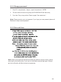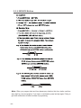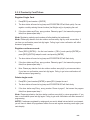
1
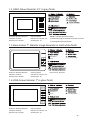
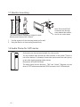
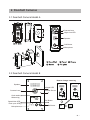
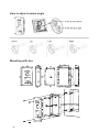
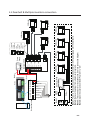
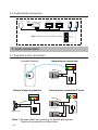
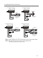
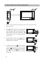
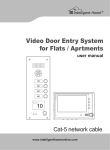
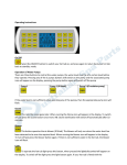
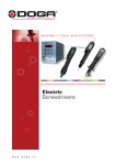
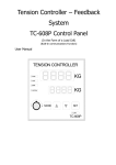
House Video Door Entry System
CAT-5 Series
Installation and User Manual
10
SPEAK
NOW
DOOR
OPEN
CALL
SERVICE
Manual covers all Genway models of CAT-5 Video monitors
and Door Stations
www.intelligenthomeonline.com
PRECAUTIONS
●● Read this manual through before using the product.
●● Slots or openings in the back of the monitor, are provided for ventilation
and to ensure reliable operation of the video monitor or equipment and
to protect if from overheating. These openings must not be blocked or
covered. The monitor should never be placed near or over a radiator or
heat register and should not be placed in a built-in installation such as a
bookcase unless proper ventilation is provided.
●● All parts should be protected from violence vibration. Prevent impacts,
knocking and dropping.
●● Clean the LCD monitor with Plastic Protection cleaner only.
●● Image distortion may occur if the video door phone is mounted too close
to magnetic field e. g. Microwaves, TV, computer etc.
●● Please keep away the video door monitor from wet, high temperature,
dust, and caustic and oxidation gas in order to avoid any unpredictable
damage.
●● Do NOT open the device in any condition, call the administrator for help
if there is any problem or mulfunction happens.
CONTENT
1. Video Monitors- - - - - - - - - - - - - - - - - - - - - - - - - - - - - - 1
2. Doorbell Cameras- - - - - - - - - - - - - - - - - - - - - - - - - - - 4
3. Power Supply and Distributor - - - - - - - - - - - - - - - - - - - 6
4. System connections- - - - - - - - - - - - - - - - - - - - - - - - - - 7
5. Lock connections- - - - - - - - - - - - - - - - - - - - - - - - - - - 11
6. Basic Video Door Phone Operation - - - - - - - - - - - - - - 13
7. Mute function- - - - - - - - - - - - - - - - - - - - - - - - - - - - - - 14
8. Card Reader/Service Button (Doorbell Model B)- - - - - 14
9. Remote Control programming(Doorbell Model B) - - - - 15
1. Video Monitors
1.1 CYGNI Colour Monitor 7” brushed aluminium finish
Dimensions: W220xH150xD25mm
Full Duplex. Handsfree.
Resolution: 480 x 234 pixel
Ding-dong ringtone
Ring time: 30s;
Talkwall
time:mounting
120s;
Direct
Monitoring time: 15s
Mounting with 86 box
145~160 cm
1.2 LUNA Colour Monitor 7” Piano Black finish
The recommended installation heights for both
Monitor and Camera 145~160mm.
Dimensions:W220xH150XD25mm
Full Duplex. Handsfree.
Resolution: 480 x 234 pixel
Ding-Dong ringtone
Ring time: 30s; Talk time: 120s;
Monitoring time: 15s
1.3 VELA Colour Monitor 5” glass finish
Dimensions: W220xH150xD25mm
Full Duplex. Handsfree.
Resolution: 320x 234 pixel
-1-
Ding-dong ringtone
Ring time: 30s; Talk time: 120s;
Monitoring time: 15s
Mute button
Reserved
Reserved
1.4 JUNO Colour Monitor 3.5” in grey finish
Dimensions: W180xH120xD25mm
Full Duplex. Handsfree.
Resolution: 320 x 234 pixel
Ding-dong ringtone
Ring time: 30s; Talk time: 120s;
Monitoring time: 15s
Note: To disable the Alarm function
a) insert 9-pin plug into terminal on the rear of monitor
b) twist together (short) all 9 wires
1.5 Muse Colour 7" Monitor Image Recorder in matt white finish
Mute button
Home
Dimensions: W224xH140xD24mm
Full Duplex. Handsfree.
Resolution: 800 x 480 pixel
Ding-dong ringtone
Ring time: 30s; Talk time: 120s;
Monitoring time: 15s
Concierge button
Picture memory: 50 pictures
1.6 LYRA Colour Monitor 7” in gloss finish
Mute button
Home
Dimensions: W235xH140xD29mm
Full Duplex. Handsfree.
Resolution: 480 x 234 pixel
Concierge button
Ding-dong ringtone
Ring time: 30s; Talk time: 120s;
Monitoring time: 15s
-2-
145~160 cm
1.7 Monitor mounting
The recommended installation heights for both
Monitor and Camera 145~160mm.
Note: Enure that RJ45
connector has enough
room behind the monitor
and is not under stress
1. Use the screws to fix the mounting bracket on the wall;
2. Hang the Monitor on the mounting bracket firmly.
1.8 Audio Phone for CAT5 series
Audio phone can be connected instead of a video monitor.
You can combine audio phones and video monitors in one system. There is a
limit of four devices. For example, three video monitors and one audio phone;
or two video monitors and two audio phones.
Dimensions: W70xH215xD30mm
The audio phone has two functions, “Talk” and “Unlock”. Requires only two
wires of CAT5 cable terminated with RG45 connector into 4110S distributor.
-3-
2. Doorbell Cameras
2.1 Doorbell Camera Model A
Camera Lens
Night-view LED
Speaker
Call Button
Microphone
2.2 Doorbell Camera Model B
How to change name tag
Speaker
Infrared LED
Camera Lens
Infrared Sensor
Card reader
&Name tag
10
Speak Now LED
Door open LED
Microphone
SPEAK
NOW
DOOR
OPEN
CALL
10
SPEAK
NOW
DOOR
OPEN
CALL
SPEAK
NOW
SERVICE
DOOR
OPEN
CALL
SERVICE
Call Button
SERVICE
10
Service Button
plastic tag
paper
-4-
How to adjust camera angle
Mounting with box
-5-
3. Power Supply and Distributor
3.1 Power supply 4001
AC-DC Input: AC180V~270V 50~60Hz Output: DC35V 1,4A
Wall mount with screws supplied. Connect N L and Earth to the mains, connect GRN and DC+
according to diagram
Mains input
N
L
Power Supply 4001
GND DC+
DC output
3.2 Distributor 4110s
Working Voltage DC30-35V
Working Current: <90mA
For star connection of up to a 4 video monitors/Audio telephones
Open sliding cover and set DIP switch number 1 into On position.
LA
LB
VFVF+
AFAF+
GND
DC+
Power can be connected to either door station or 4110S distributor. If power supply connected to
4110S use DC+ for brown and GND for brown/white
ON
Distributor 4110S
DIP
to doorbell
to monitors
-6-
-7-
Doorbell
1. Orange/white
2. Orange
3. Green/white
4. Blue
5. Blue/white
6. Green
7. Brown/white
8. Brown
Power supply
+
-
Note 1
Cat-5
Power supply
12345678
12345678
Monitor
1. Orange/white
2. Orange
3. Green/white
4. Blue
5. Blue/white
6. Green
7. Brown/white
8. Brown
Note 2: With single monitor systems, place jumper supplied into position shown.
Note 3: This connector is for lock connection. See lock connection diagram.
Note 1: For distance over 50m, the doorbell needs to be connected to a 4001 power supply.
12345678
12345678
Note 3
Note 2
1~8
Monitor
4. System connections
System requires CAT-5 or CAT-6 cabling and RG45 connectors (not supplied by default)
Over 100m and up to 150m an additional power supply recommended.
Working distance up to 100m with one power supply
Maximum number of video monitors or Audio handsets in one system: 4
Second door station can be added; requires additional LAN switch
4.1 Doorbell A single monitor connection
LA LB VF- VF+ VF- AF+ GND DC+
Orange/white
CALL
SERVICE
Green
10
Blue/white
DOOR
OPEN
Blue
Power supply
Brown/white
SPEAK
NOW
Doorbell
Brown
Green/white
Orange
-
Power supply
Cat-5
+
Note 2
Note 1: Keep this jumper on for single monitor systems.
Note 2: This connector is for lock connection. See lock connection diagram.
Doorbell back view
Note 1
12345678
12345678
1. Orange/white
2. Orange
3. Green/white
4. Blue
5. Blue/white
6. Green
7. Brown/white
8. Brown
Monitor
1~8
Monitor
4.2 Doorbell B single monitor connection
-8-
-9-
Note 5
Power
Supply
1. Orange/white
2. Orange
3. Green/white
4. Blue
5. Blue/white
6. Green
7. Brown/white
8. Brown
Distributor 4110S
Distributor 4110S
LA
AFVF+ PORT2
VFLB PORT1
DC+ PORT4
GND
AF+ PORT3
4# Monitor
-
+
3# Monitor
Power
Supply
2# Monitor
1# Monitor
4# Monitor
1# Monitor
2# Monitor
3# Monitor
Note 1: For distance over 50m, the doorbell needs to be connected to a power supply. You can connect the power
either from a 4001 power supply or 4110s distributor.
Note 2: Remove the jumper for multiple-monitor systems.
Note 3: This connector is for lock connection. See lock connection diagram.
Note 4: All RJ45 connectors have to be wired according to diagram.
Note 5: Open the cover and set the DIP switch 1 to “On”.
Doorbell
Camera
12345678
12345678
Note 4
Note 3
Note 2
Note 1
4.3 Doorbell A multiple monitors connection
SERVICE
Note 4
Blue/white
Orange/white
Note 3
Note 1
+
LA
AFVF+ PORT2
VFLB PORT1
DC+ PORT4
GND
AF+ PORT3
12345678
3# Monitor
Power
Supply
Distributor 4110S
4# Monitor
-
2# Monitor
3# Monitor
2# Monitor
1# Monitor
4# Monitor
1# Monitor
1. Orange/white
2. Orange
3. Green/white
4. Blue
5. Blue/white
6. Green
7. Brown/white
8. Brown
Note 1: Power to the doorbell can be connected either from 4001 power supply or 4110s distributor.
Note 2: Remove the jumper for multiple monitor systems.
Note 3: This connector is for lock connection. See lock connection diagram.
Note 4: Open the cover and set the DIP switch 1 to “On”.
CALL
Orange
10
Green/white
DOOR
OPEN
Green
SPEAK
NOW
Blue
Distributor 4110S
Brown/white
Power
Supply
Brown
Doorbell
Doorbell back view
LA LB VF- VF+ VF- AF+ GND DC+
Note 2
12345678
4.4 Doorbell B Multiple monitors connection
-10-
4.5 Audio phone connection
Doorbell
Power
Supply
Audio phone
Distributor 4230
Audio phone
2# Monitor
1# Monitor
12345678
Note: Connect 1 to 4th, 2 to 5th. No polarity
12345678
4. Blue
5. Blue/white
5. Lock connections
5.1 Doorbell A lock connection
Doorbell Model A
Normal open connection
COM
NC
NO
Note 1
Electric lock
+
Normal closed connection
COM
NC
-
Normal open connection-2 locks
COM
NO
NC
NO
Note 1
Note 1
Electric lock
Magnetic lock
+
-
+
Note 1: Reverse diode not used only for electric gate system.
Must be connected for all other locks.
-11-
-
GS
INDOOR
GND
NO
NC
COM
12V OUT
GS
INDOOR
GND
NO
NC
COM
12V OUT
5.2 Doorbell B lock connection
Magnetic lock
-
Note 1
+
Electric lock
Note 2
12V OUT
GS
INDOOR
GND
NO
NC
COM
GS
INDOOR
GND
NO
NC
COM
12V OUT
Note 2
Note 2
Electric lock
-
Electric lock
+
+
-
Note 2
Electric lock
Note 2
Note 1: Short COM and 12V OUT if lock doesn't have it's own power supply.
Note 2: Reverse diode not used only for electric gate system.
Must be connected for all other locks.
-12-
6. Basic Video Door Phone Operation
1. When a visitor presses the 'Call' button, the monitor rings and screen
shows the visitor.
2. Press
Button to talk. If you choose not
to answer, the system will automatically
reset to standby after 60 seconds. Press
Button again to end the conversation; the
conversation will be cut off automatically after
120 seconds.
3. During ringing or talking, press
Button to
unlock the door. (A Di~ sound will prompt to
indicate the door is opened)
4. In standby mode, press
Button to monitor
outside. If two doorbells were installed,
pressing
Button shows view of Doorbell 1,
press
to end; press
one more time to
view Doorbell 2. (Monitoring time is limited to
60 seconds)
-13-
7. Mute function
1. When you do not want to be disturbed
by any calling, you can turn on the mute
function.
Mute
indicator
2. A d j u s t t h e
[ R i n g Vo l u m e
Adjustment] to the lowest, the ring will
Ring Volume Adjustment
be completely turned off, and the
indicator will be turned on.
8. Card Reader/Service Button (Doorbell Model B)
SERVI
●●
Card: Swipe any registered card on the card reader to release the door.
●●
Service/Trade Button: During the time specified for allowing trades-people or maids
access, press SERVICE button on the doorbell to release the door. This button is especially for
deliverymen or other service people. The function has to be programmed by the remote control.
See next section for remote control details.
-14-
9. Remote Control programming(Doorbell Model B)
9.1 Key panel discriptions
Requires 2 x 1.5V AAA Batteries
(not supplied)
Working distance for programming
< 1m
9.2 Programming
To be able to do programming, first get into the programming mode.
9.2.1 Get into the system
1. Press (FN) + password (4 digits) + (ENTER). Note: default password is 1234
2. The door station will sound a long beep and DOOROPEN LED will flash slowly. You
have 7s to enter the password, otherwise system will exit automatically.
3. If wrong password was used the door station will say “Sorry, wrong number. Please try
again”. Repeat step 1 with correct password.
4. To exit programming mode, press (EXIT). Or system will exit automatically if no activity
in 2min.
5. During programming bell button and service button are not responsive.
-15-
9.2.2 Change password
1. Press FN + new password ( 4 digits) + repeat new password + ENTER
2. The door station will sound a long beep and DOOROPEN LED will flash slowly.
3. If you hear “Sorry, wrong number. Please try again” then repeat step 1
Note: Please memorize your new password. If you forget your new password please call
Distributor for help to reset a password
9.2.3 Date and time
Note: When you program the date and time please pay attention that door station confirms
every digit by voice annunciation. If you hear no confirmation press last digit again. Failing to
get voice confirmation will affect success of programming
-16-
9.2.4 SERVICE Button
Note: When you program date and time please pay attention that door station confirms
every digit by voice annunciation. If you hear no confirmation press last digit again. Failing to
get voice confirmation will affect success of programming.
-17-
9.2.5 Proximity Card/Token
Register Single Card
1. Press[REG-]+card number + [ENTER]
2. The door station will sound a long beep and DOOROPEN LED will flash quickly. You can
register a card by entering the card number (last 8 digits only) or by swiping the card.
3. If the door station says"Sorry, wrong number. Please try again", that means the program
failed, then please repeat step 1.
Note: Registering cards by card numbers will allow deleting lost cards easily.
Note: Please pay attention that door station confirms every digit by voice annunciation. If
you hear no confirmation press last digit again. Failing to get voice confirmation will affect
success of programming.
Register continuous cards
1. Press [REG-]+[EXTRA] + the first card number + [DEL+]+card quantity+[ENTER] or
press [REG-]+[EXTRA]+swipe the card +card quantity+[ENTER]
2. The door station will sound a long beep and DOOROPEN LED will flash slowly
3. If the door station says"Sorry, wrong number. Please try again", that means the program
fialed, then please repeat step 1.
4. Note: Please pay attention that door station confirms every digit by voice annunciation.
If you hear no confirmation press last digit again. Failing to get voice confirmation will
affect success of programming.
Delete single cards
1. Press[DEL+]+card number+[ENTER] or press [DEL+]+swipe the card.
2. The door station will sound a long beep and DOOROPEN LED will flash slowly.
3. If the door station says"Sorry, wrong number. Please try again", that means the program
fialed, then please repeat step 1.
Note: Please pay attention that door station confirms every digit by voice annunciation. If you
hear no confirmation press last digit again. Failing to get voice confirmation will affect success of
programming
NOTE: If cards were registered by swiping and you want to delete lost card which is not present,
you will have to delete all programmed cards at once and register remaining cards again (see
next chapter)
-18-
Delete all cards
1. Press DEL+EXTRA+password+ENTER
2. Door station will sound a long beep and DOOROPEN LED will flash slowly. Press EXIT
button to exit programming mode.
9.2.6 Unlock time
1. Press[UNLOCK] +Number(1~10) + [ENTER]
2. The door station will sound a long beep and the DOOROPEN LED will flash slowly.
3. If you hear “Sorry, wrong number. Please try again” repeat step 1 and make sure that
unlocking time is between 1 second and 10 seconds (1 – 10)
9.2.7 Door Station Ring Tone and Volume
1. Press RING + Number (1~4) + ENTER.
2. 2. The door station will sound a long beep and the DOOROPEN LED will flash slowly.
3. 3. If you hear “Sorry, wrong number. Please try again” repeat step 1 and make sure that digit
is between 1~4.
NOTE: There are 4 optional ring tones to choose from.
1. Press RING + REG- + ENTER to increase
2. RING + (DEL+) + ENTER to decrease ring volume
NOTE: There are 1-2-3-4 levels of volume available. Level 1 is “Mute” and turns voice
annunciation Off
-19-
WARRANTY CARD
NB Please keep this document safe, as it is proof of your Warranty
Your Video door system comes with a one year Manufacturers Warranty. When
used normally, the following services are offered:
1. Replacement for malfunctioning parts in first three months
2. Repair free of charge for malfunctioning parts in first year
The following actions will void the Warranty:
1. Damage to the device during installation
2. Damage to the device through misuse
3. Opening and/or disassembling the device
4. Attempting to force the device to perform functions for which it is not intended
5. Attaching the device to power supplies other than those recommended by
the manufacturer
Distributor for Warranty purposes:
Intelligent Home Online Ltd
34a High Street, Hornsey, London, N87NX
+44 (0)20 83482040
www.intelligenthomeonline.com
Product:_____________________________________________
Serial Number: ______________________________________
Invoice N: ____________________________________________
Purchase Date_________________________________________
CAT5-series-V2 2013-07-01
The design and specifications can be changed without notice to the user.
Right to interpret and copyright of this manual are preserved.
www.intelligenthomeonline.com