1
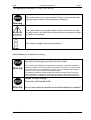
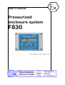
User's manual Pressurized enclosure system F830 manual_f830_z22_v1.0.6_2012.doc, Rev.0 F830 1 Introduction Page 2 Contents 1 Operation instruction for Explosion protected device................................................................4 2 General requirements to pressurized enclosure system F830/F840 .........................................5 2.1 General requirements ................................................................................................................5 2.2 Mechanical requirements to the Ex pz- housing........................................................................5 2.3 Determination of pre- purging period .........................................................................................6 2.4 Purge medium requirements......................................................................................................7 2.5 Temperature class of the Ex pz- housing ..................................................................................7 2.6 Particular requirements in zone 22 (Dust hazardous area).......................................................8 2.6.1 Pre purging / cleaning of the housing .................................................................................8 2.6.2 Markings on the housing ....................................................................................................8 2.6.3 Special conditions in the manual of the Ex pD of system (Zone 22)..................................8 3 Introduction: simplified pressurized enclosure system .............................................................9 3.1 Pressurized enclosure system F830..........................................................................................9 3.1.1 Pressurized enclosure system F830 / F840 comparison .................................................10 3.2 Pre- operation phase ...............................................................................................................10 3.2.1 Pressurized enclosure system without pre- purging ........................................................10 3.2.2 Pressurized enclosure system with pre- purging..............................................................10 3.3 Operation mode “Leakage compensation” ..............................................................................11 3.4 Conformity with Standards.......................................................................................................11 4 Mounting and Connecting............................................................................................................12 4.1 Mounting, Dimensions .............................................................................................................12 4.1.1 Control device FS830 .......................................................................................................12 4.1.2 Sinter metal throttle...........................................................................................................12 4.1.3 Optional solenoid valve for purging ..................................................................................12 4.1.4 Spark barrier .....................................................................................................................13 4.2 Connecting and starting ...........................................................................................................13 4.2.1 Connection of Ex e clamps ...............................................................................................13 4.2.2 Terminals of the FS830 ....................................................................................................13 4.3 Power off relays .......................................................................................................................14 5 Configuration and operation........................................................................................................15 5.1 Display .....................................................................................................................................15 5.2 Alarm monitor Lamp.................................................................................................................15 5.3 Keyboard..................................................................................................................................15 5.4 Indication modes during normal operation...............................................................................16 5.5 How to enter and leave the bypass mode ...............................................................................16 5.6 Configuration............................................................................................................................16 5.6.1 The menu format ..............................................................................................................16 6 Annex .............................................................................................................................................19 6.1 Terminals and Terminals Ex- limits..........................................................................................19 6.2 Technical details ......................................................................................................................19 6.2.1 Valid air pressure values ..................................................................................................20 6.3 Dimensions ..............................................................................................................................21 6.4 Flow chart.................................................................................................................................22 6.5 Flow rate table..........................................................................................................................23 6.6 Problems and solutions............................................................................................................23 6.7 Type codes...............................................................................................................................23 6.8 Transport, Storing, Repairs und Disposal................................................................................24 6.9 Ex –protection class of control unit FS830 ..............................................................................24 6.10 List of Parameters ....................................................................................................................25 Gönnheimer Elektronic GmbH phone: +49(6321)49919-0, fax: -41 Email: [email protected] F830 1 Operation instructions Page 3 The symbols WARNING, CAUTION, NOTE This symbol warns of a serious hazard. Failure to observe this warning may result in death or the destruction of property. This symbol warns of a possible failure. Failure to observe this caution may result in the total failure of the device or the system or plant to which it is connected. This symbol highlights important information. Safety Measures: to read and to comply Warning! Extreme caution is advised when handling this device. High electrical discharge is possible and can be fatal. Work on electrical installations and apparatus in operation is generally forbidden in hazardous locations, with the exception of intrinsically safe circuits. In special cases work can be done on non-intrinsically safe circuits, on the condition that during the duration of such work no explosive atmosphere exists. Only explosion protected certified measuring instruments may be used to ensure that the apparatus is voltage-free. Grounding and short-circuiting may only be carried out, if there is no explosion hazard at the grounding or short circuit connection. Danger of static charge! Clean only with humid cloth! Do not open when an explosive dust atmosphere is present! Gönnheimer Elektronic GmbH phone: +49(6321)49919-0, fax: -41 Email: [email protected] F830 1 1 Operation instructions Page 4 Operation instruction for Explosion protected device Application and Standards This instruction manual applies to explosion-protected devices of types below. This apparatus is only to be used as defined and meets requirements of EN 60 079 particularly EN60 079-14 "electrical apparatus for potentiality explosive atmospheres". Use this manual in hazardous locations, which are hazardous due to gases and vapours according to the explosion group and temperature class as stipulated on the type label. When installing and operating the explosion protected distribution and control panels you should observe the respective nationally valid regulations and requirements. General Instructions Work on electrical installations and apparatus in operation is generally forbidden in hazardous locations, with the exception of intrinsically safe circuits. In special cases work can be done on nonintrinsically safe circuits, on the condition that during the duration of such work no explosive atmosphere exists. Only explosion protected certified measuring instruments may be used to ensure that the apparatus is voltage-free. Grounding and short-circuiting may only be carried out, if there is no explosion hazard at the grounding or short circuit connection. To achieve an impeccable and safety device operation, please take care for adept transportation, storage and mounting, as well as accurate service and maintenance. Operation of this device should only be implemented by authorised persons and in strict accordance with local safety standards. The electrical data on the type label and if applicable, the "special conditions" of the test certificate TÜV 03 ATEX 2095 X are to be observed. For outdoor installation it is recommended to protect the explosion protected distribution and control panel against direct climatic influence, e.g. with a protective roof. The maximum ambient temperature is 40°C, if not stipulated otherwise. Terminal compartment in Increased Safety When closing, it is to be ensured that the gaskets of the terminal compartment remain effective, thus maintaining degree of protection IP 54 according to EN 60529. Close unused entries by impact-proof stopping plugs, which are secured against self-loosening and turning. Maintenance Work The gaskets of Ex e enclosures are to be checked for damages and replaced, if required. Terminals, especially in the Ex e chamber are to be tightened. Possible changes in colour point to increased temperature. Cable glands, stopping plugs and flanges are to be tested for tightness and secure fitting. Intrinsically Safe Circuits Erection instructions in the testing certificates of intrinsically safe apparatus are to be observed. The electrical safety values stipulated on the type label must not be exceeded in the intrinsically safe circuit. When interconnecting intrinsically safe circuits it is to be tested, whether a voltage and/or current addition occurs. The intrinsic safety of interconnected circuits is to be ensured. (EN 60079-14, section 12) Gönnheimer Elektronic GmbH phone: +49(6321)49919-0, fax: -41 Email: [email protected] F830 2 2 General requirements to F830 Page 5 General requirements to pressurized enclosure system F830/F840 The pressurized enclosure control device (FS830) can be combined with every Ex pz- housing that full fills the following requirements. 2.1 2.2 General requirements 1 The Ex pz system must be inspected by a skilled person of accordance to IEC 60079 –2, EN 60079 –14 and this manual. 2 Mount the solenoid valve (purging medium input) and control unit FS830 to an maximum of distance (optimal arrangement is diagonal) 3 The operator must not do any technical changes to the control unit FS830. Any change will invalidate the conformity statement TÜV 03 ATEX 2095 X. 4 Any maintenance activities has to be done by Gönnheimer Elektronic GmbH 5 Corrupt Ex p- pipe connections have to be repaired immediately 6 The introduction of flammable gas into the Ex pz- housing, e.g. for gas analyser application, is prohibited. Mechanical requirements to the Ex pz- housing 1 Regard particularly IEC 60079-2, section 7 2 The Ex pz- housing must hold the 1,5 – fold of the maximum pressure, which can be reached inside of the cabinet, 2 mbar at least. The operator has to define the maximum pressure of the housing and has to program this pressure value as monitored max. pressure into the FS830. 3 The Ex pz- housing must pass a impact test according DIN EN 50021 Table 13 4 The protection class of the Ex pz- housing must be greater than IP40. 5 Cable glands must have a protection class greater than IP54. 6 If the Ex pz- housing has surface made of synthetics (e.g. windows) with an area greater than 100 cm², than a warning sign against electro static discharge is necessary. Caution ! Danger of static discharge. Clean only with humid cloth! 7 There is no danger of static discharge, if the synthetic surface has a thickness of ≤ 0,2 mm (Group IIC) respectively 2 mm (Group IIB) or less and it is mounted on a metallic ground. 8 If the Ex pz- housing posses internal compartments the installer has to obey the following rules: a) Components with a free internal volume less than 20 cm³ are not considered to be internal compartments requiring purging as long as the total volume of all such components is not more than 1% of the free internal volume of the pressurized apparatus. (IEC 60079 – 2; Abs. 5.5.4) b) Provide not less than 1 cm² of vent area for each 1000 cm³, with a minimum vent size of 6,3 mm diameter should be allow for adequate purging. (IEC 60079 – 2; Abs. 5.5.2) c) Place the vents in a diagonal order, as shown on the picture below, with a minimum vent size of 6,3 mm diameter Gönnheimer Elektronic GmbH phone: +49(6321)49919-0, fax: -41 Email: [email protected] F830 2 General requirements to F830 Page 6 d) Installer can also remove covers or doors of internal housings if they provide adequate vent diameters alternatively. e) If the topics above are not applicable, a separate piping must be added to the internal compartment. The purge medium flow through the compartment must be high enough to make sure that the air in the compartment is exchanged at least 10 times higher. For instance: 2.3 Determination of pre- purging period If its not sure, at power up, that the atmosphere inside of the enclosure and the appropriate pipes is below 25% of the lower explosive limit (LEL) (EN 60079 – 14 chapter 13.4), a prepurging of the pressurized enclosure is necessary. The pre purging of the housing is prohibited, by an Ex pD system (pressurized enclosure in zone 22). Gönnheimer Elektronic GmbH phone: +49(6321)49919-0, fax: -41 Email: [email protected] F830 2.4 2.5 2 General requirements to F830 Page 7 Purge medium requirements 1 The purging medium must not be derived from hazardous area, it must be contamination free ( dry, free of oil and dust) 2 The temperature of the purge medium should not exceed 40°C. 3 If another purge medium than air is used, it is important to regard the minimum oxygen content of the ambient. Maybe it is necessary to install a exhaust pipe from the LA830 to out-of-door. 4 The inlet and the outlet of the purging gas should be located as far away to each other as possible. 5 The pressure lost an the solenoid valve (PValve) must not be higher than 500 mbar, while pre- purging. Temperature class of the Ex pz- housing The installer has to define the maximum ambient temperature and the resulting maximum temperature class of the Ex pz- housing. To determine the temperature class, measure, on worst conditions, the hottest point on the surface of the Ex pz housing and recalculate it to the maximum ambient temperature. The minimum temperature class is the one of the FS830 and its surface temperature. If some parts inside of the housing get hotter than the temperature class, the installer has to determine the time in which the temperature of those parts falls below the temperature class. He has to place a sign on the Ex pz- housing with the following sentence: Power off the apparatus and wait for x minutes for cool down ! X is the determinate time multiplied with a safety factor 1,5. Gönnheimer Elektronic GmbH phone: +49(6321)49919-0, fax: -41 Email: [email protected] F830 2 General requirements to F830 Page 8 2.6 Particular requirements in zone 22 (Dust hazardous area) 2.6.1 Pre purging / cleaning of the housing For the employment in the zone 22 the FS830 must not init a pre purging phase. Therefore, the automatic purging at the controller FS830 has to be deactivated. The purging phase before the start-up of the inserted, electrical non-ex operational funds, upstream within the gas ex range, is replaced in the zone 22 by inside cleaning the housing. 2.6.2 Markings on the housing On the housing has to be the following markings: „WARNING: REMOVE ALL DUST FROM THE INSIDE OF THE ENCLOSURE BEFORE CONNECTING OR RESTORING THE ELECTRICAL SUPPLY“ On ex p-housings for zone 22 with doors without tools to be opened, must the following reference be attached: „WARNING: DO NOT OPEN WHILE ENERGIZED UNLESS IT IS OBVIOUS THAT NO COMBUSTIBLE DUST IS PRESENT“ 2.6.3 Special conditions in the manual of the Ex pD of system (Zone 22) In the manual for Ex pD applications for the zone 22 the following items are supplemented: The use of the Ex pD application within the zone 22 must take place without pre purging period phase. The automatic flushing at the controller FS830 is to be therefore always deactivated. The system may be operated not with a single solenoid valve, but only with a leakage balance mechanism without flushing attitude. Before start-up of the ignition capable apparatus, the inside of the housing is to be cleaned completely. The protective class of the Ex pD housing in dust explosive area with not leading-capable dust has to be at least to IP5X, with leading-capable dust at least IP6X. Gönnheimer Elektronic GmbH phone: +49(6321)49919-0, fax: -41 Email: [email protected] F830 3 3 Configuration and operation Page 9 Introduction: simplified pressurized enclosure system The use of pressurized enclosures allows the operation of ‘non explosion protected’ standard devices inside hazardous areas. The protection type ‘pressurization’ (Ex p) is based on the principle of keeping a constant cabinet pressure with a protective purge gas, to prevent the hazardous area from entering the cabinet. Generally, before start-up, the pressurized enclosure must be purged with air or protective gas to remove any explosive mixture that may be inside the enclosure. This automatic procedure is called purging process. See chapter 2 for general requirements of pressurized enclosure and integrated ignition capable apparatus. 3.1 Pressurized enclosure system F830 The device FS830 is the control device of a F830 - pressurized enclosure system. An simplified pressurized enclosure system F830 (Zone 2) consists of three components and the enclosure. 1. Control unit for process control and monitoring 2. Sinter metal throttle SD840 to control air input fed by pressured air network 3. Purge gas outlet (Vent) LA830.x The pressurized enclosure system F830 is featured with a flexible system configuration with separate installation of the inlet valve, outlet valve and control unit. The inlet valve (solenoid valve SVD.L) and the outlet valve (LA830) can be mounted at various places at the pressurized cabinet. The compact control unit FS830 can be integrated user-friendly direct into the cabinet wall. Figure 1 Block diagram In case of higher flow rates during the purging phase, multiple outlet valves LA830 can be in-stalled to shorten the purge time. Due to the integrated spark barrier inside the LA830, the purge air can leave the cabinet directly into the hazardous area. The control unit FS830 can be connected from the inside of the Ex pz- housing without the need of additional cable glands or tube connections. In some applications, the Ex- protection by a simplified pressurization system allows an operation without pre- purging of the cabinet. Thereby the solenoid valve (SVD.L) can be replaced by the adjustable leakage compensation nozzle SD840. The nozzle SD840 is also used for dust- Ex, Zone 22 applications. Gönnheimer Elektronic GmbH phone: +49(6321)49919-0, fax: -41 Email: [email protected] F830 3.1.1 3 Configuration and operation Page 10 Pressurized enclosure system F830 / F840 comparison The Pressurized enclosure system F830 and F840 are certified together in one common EC- type certificate. Hence, the EC- type certificate of the F840 is listed in the appendix of this manual. The special conditions for the F830 system are to be found in the second supplement. 3.2 Pre- operation phase 3.2.1 Pressurized enclosure system without pre- purging If the operator is sure, that the atmosphere inside of the enclosure and the appropriate pipe infrastructure is below 25% of the lower explosive limit (LEL) (EN 60079 – 14 chapter 13.4) at power up, he can abandon the pre purging of the enclosure in zone 2. In that case the FS830 monitors only the pressure inside of the enclosure on 0.8 mbar at minimum and maximal 22.0 at maximum. If any limit is exceed, the FS830 changes the state on relay(s) output(s). The purge medium flows through an adjustable sinter metal throttle into the housing while reducing its pressure (see block diagram). In the LA830 is an outlet valve which opens at about 5 mbar and allows the purge gas to escape from the cabinet. Before this valve is a spark lattice located thus the purge medium can be exhausted directly to the hazardous area. 3.2.2 Pressurized enclosure system with pre- purging To pre- purge the housing connect a digital working 2/2 way solenoid valve (SVD.L) to the terminal 5 and 6 of the FS830. Also configure the pre- purging period into the structure menu of the control device. After pre- purging the valve closes automatically and the adjustable throttle of the SVD.L lets a small amount of purging medium into the housing to hold pressure. The installer can determine the pre- purging time once by doing the attenuation test according EN 50016 section 14.3. As an alternative he can calculate the purging time without the elaborate attenuation test see below: The purging time depends on minimum flow (Qmin), free internal volume (V) and the free volume of the connected pipes (Va). Final the calculated time must be multiplied by 10. The purging time tpurge is: t purge = 10 × (V + Va) Qmin The minimum flow (Qmin) depends on the minimum pre pressure (Ppremin), the pressure lost at the valve (PValve), internal pressure of the Ex pz- housing (PInt) and the nozzle diameter (d). The pressure lost at the valve (PValve) should not exceed 500 mbar. The maximum internal pressure of the housing is defined to be less than 20 mbar. The minimum flow Qmin can be calculated by: Qmin = 2 × ( Ppre min − PValve − PInt ) ρ d 2 ×π × 4 ρ is the density of the purging medium. The density of air is ρ =1,2393 kg/m3, the density of nitrogen is 1,25 kg/m3. WE calculate the ρ of air for all gases, because the difference is only 3%. The installer can calculate the purging time of ist own or he can use the automatic calculation in the menu of the FS830 (see also section 5.6.1) Example: Gönnheimer Elektronic GmbH phone: +49(6321)49919-0, fax: -41 Email: [email protected] F830 3 Configuration and operation QBeispiel = 2 × (2 − 0,5 − 0,025) × 105 kg m kg 1,293 3 m m s2 2 0,002 2 × m 2 × π × , 4 QBeispiel m3 l ≈ 0,0015 ≈ 1,5 s s 3.3 Operation mode “Leakage compensation” Page 11 mit 1 bar = 105 kg m s2 m2 The FS830 works after the pre purging phase or without pre purging phase immediately after the voltage supply in the mode of operation "leakage compensation ". In this mode of operation will maintain after an overpressure (at least 0.8 mbar) within the Ex p cabinet. This cabinet minimum pressure as well as also a cabinet maximum pressure are programmable and are monitored constantly. Leakage losses are compensated by a small bypass. This bypass is integrated in the valve and mechanically adjustable (diameter 0.3... 1 mm). 3.4 Location of solenoid valve fuse The fuse of the solenoid valve SVD.Lxxx is located on the upper side of the FS830. See picture below: 3.5 Conformity with Standards The ex proofed control device FS830 meets requirements of listed standards in the attachment (Declaration of conformity). They were developed, manufactured and tested in accordance with state-of-the-art engineering practice and ISO9001:2008. Gönnheimer Elektronic GmbH phone: +49(6321)49919-0, fax: -41 Email: [email protected] F830 4 Mounting and Connecting 4 Mounting and Connecting 4.1 Mounting, Dimensions 4.1.1 Control device FS830 Page 12 The control device FS830 is suitable for mounting in hazardous area zone 2. The installer can place it in or outside of the Ex pz- housing. The installer can mount the control device using the 4 mounting holes in the housing rear, but the fixing on the air in- or outlet is sufficient. While mounting, observe local safety guidelines and the regulative: EN 60079-14 Additional see general requirement to pressurized enclosure system in section 2 in this manual. The reference output (M5 screw on the left side of the control unit) must have contact the ambient pressure If the control unit is built into the Ex pz- housing the reference output must to connected to the ambient with a pipe or tube. Additional conditions for mounting in gas Ex area (Zone 2) With use of the FS830 as a device of gas Ex- group the pressurized enclosure must fulfil at least the protective class IP54 Additional conditions for mounting in dust Ex area (Zone 22) With use of the FS830 as a device of dust Ex- group IIIB the pressurized enclosure must fulfil at least the protective class IP54 With use of the FS830 as a device of dust Ex- group IIIC the pressurized enclosure must fulfil at least the protective class IP65 4.1.2 Sinter metal throttle While operation mode “leackage compensation” a small amount of purging gas enters through the sinter metal throttle SD840 into the Ex p- housing to provide the desired overpressure. Dispensable purge gas will be exhausted (at an overpressure of 3-4 mbar) through the purge air outlet (Vent) LA830. 4.1.3 Optional solenoid valve for purging The installer can mount the solenoid valve in or outside of the Ex pz housing, see details from manufacturer documentation. Gönnheimer Elektronic GmbH phone: +49(6321)49919-0, fax: -41 Email: [email protected] F830 4.1.4 4 Mounting and Connecting Page 13 Spark barrier The purge air outlet (Vent) LA830 has a spark barrier according to EN 60079-2. The exhaust air can be diverted direct to Ex area. The solenoid valve and the aerial outlet LA830 are to be mounted in the ex pz- cabinet with maximum distance to each other (e.g., arrangement in the space diagonals). 4.2 Connecting and starting 4.2.1 Connection of Ex e clamps Min. and max. min. 0,3 Nm clamping torque max. 0,4 Nm Min. und Max. wire cross- section steep: 0,2 – 2,5 mm² flexible: 0,2 – 2,5 mm² Note the following item while connecting: • LINE VOLTAGE Extreme caution is advised when handling this device. High electrical discharge is possible and can be fatal. • See Installation regulative EN 60079-14 as well as Conformity statement TÜV 03 ATEX 2095X • Do not exceed terminal safety limits of each terminal See limits in technical details or declarations of conformity. • The internal solenoid valve fuse must be adapted to the solenoid valve 4.2.2 Terminals of the FS830 Terminal Comment 1,2 3,4 5,6 6,7,8 N 9,10 L + 11,12,13 Relay contact 1 Relay contact 2 Terminal for solenoid valve, 5 = V, 6 = NMains, according to model conductor N or minus by DC Mains, according to model conductor L1 or plus by DC PE – GND, Ground Gönnheimer Elektronic GmbH phone: +49(6321)49919-0, fax: -41 Email: [email protected] F830 4.2.3 4 Mounting and Connecting Page 14 Place and exchange of solenoid fuse The fuse of the solenoid valve SVD.Lxx is located on the bottom side of the controller. If the solenoid valve doesn't work, you should check the fuse. 4.2.4 Power off relays The control unit FS830 switches off the line voltage the the target device via the clamps 1,2 and 3,4. The switching power is 250V / 5A. The maximum current limits (5 A) on the clamps 28,29 and 30,31 should not be exceeded at any time! E.G. By an application of switched power supply a multiple higher current as the nominal max. current may occur. In this case a switching on current limitation (e.g., NTC) must be added to avoid the off-limits high current. If this is missed the risk of the „jammed relay contacts“ and within the loss of the explosion protection exists!! 4.2.5 Block diagram of the FS830 Block diagram of the FS830 Gönnheimer Elektronic GmbH phone: +49(6321)49919-0, fax: -41 Email: [email protected] F830 5 5 Configuration and operation Page 15 Configuration and operation Configure the F830 with the 4 keys and the display. 5.1 Display The built-in 8- figures display indicates operation modes, present pressure or flow rate data, as well as malfunctions. 5.2 Alarm monitor Lamp The FS830 has a monitor lamp below the display. This red lamp (LED) blinks if the pressure inside of the Ex p- housing is below the defined minimum pressure. In bypass mode the LED is permanently on and in normal operation the lamp is off. Ñ Lamp Meaning flashing The pressure inside of the cabinet is below 0.8 mbar ! No explosion proof inside cabinet! Constant on Bypass mode is active – no explosion proof inside cabinet! 8 Constant off Ex protection is “OK” = normal operation 5.3 Keyboard The four multi-functional keys have different meanings and functions depend on the present operation mode. Key „Shift right“-button BYPASS Operation mode Function normal operation none running menu Shift cursor one position right. normal operation Activates Bypass; i.e. enable toggle ignition-capable device on or off independently of the purging status ! (Be sure, that no explosive atmosphere is in environment) „Up“-button INFO running menu normal operation Get next menu item Changes indication of the display: present pressure, flow rate, remaining purge time and present state of the purging system running menu Get previous menu item normal operation Enters main menu running menu Initiates and confirms parameter input „Down“-button MENÜ „Enter“- button Gönnheimer Elektronic GmbH phone: +49(6321)49919-0, fax: -41 Email: [email protected] F830 5.4 5 Configuration and operation Page 16 Indication modes during normal operation The actual status of the Ex pz- System is generally shown on the info display. Using the “Down- button the user can toggle to the pressure and remaining purge time indication. 5.5 How to enter and leave the bypass mode Utilizes bypass only, if it is sure that no explosive atmosphere is inside the cabinet! Fire certificate required! The bypass mode is denied, if it is possible that a explosive atmosphere can arise inside the Ex p- housing! Standard situation is the FS830 is in normal operation. The origin state is normal operation, the Ex p housing can be purged, unpurged or while purging. By-CODE 0002 The bypass code is needed The ex works Bypass code is ‘0002’. Enter is right code using the arrow keys and confirm with the ENTER- key. Bypass The bypass mode is now active. If the control unit is set to “automatic on” the display shows “bypass” and “On” alternately and the relay contacts (Ter. 11,12 and 13,14) are closed. Now you can toggle the relay contacts by pressing the “right-“ button. Remark: if the E/A- code is unequal to zero, you must enter them each time you want to change the relay contacts state. 5.6 Configuration You must configure and enter the parameters of the control unit FS830 to achieve a desired mode of operation. All parameters of the control unit are structured in form of a menu. The Master Code (M-Code) ex works is: 0001 5.6.1 The menu format In the following table below shows explanations of the menu items. The table works as a reference guide for programming the desired system structure and to set the appropriate parameters correctly. The menu items are roughly sorted by class. Gönnheimer Elektronic GmbH phone: +49(6321)49919-0, fax: -41 Email: [email protected] F830 5 Configuration and operation Page 17 Please note that the viewable conditions of parameters are not included. Classification 1.Level 2.Level 3.Level Language Structur Purging Purg. Y. Purg. N. Auto Auto. Y. Auto.N. O1 Func. none O-Ex ok O-Bypas O-Purg. O-.Signal O-Pmax Param. O2 Funkt. none O2 no/nc. no O2 no/nc. no Pur. Time Pur. Vol. Gönnheimer Elektronic GmbH Description, Explanation Define the language shown on the display of the FS830 in this menu item. Available languages are: German, English, French, Dutch, Spanish „Purg. Y.“ means that the Ex pzhousing will be pre purged before “Ex Ok” Message is set „Purg.N.“ means that the housing will not be pre- purged. The “Ex Ok” Message is set and the min. Pressure is monitored Automatic purging time Yes: The FS830 calculates the purging time out of pre- pressure, nozzle diameter Automatic purging time No (= Enter the purging time directly): Define the function of output O1 (te. 1/2). Explosion protection is ok: The output is set, if the pressure is higher than minimum. Bypass- output: The output is high, if the bypass is active Purging- output: The output is high as long the pre- purging procedure is running Signal pressure- output: the output is high, if the actual pressure inside of the Ex pz- housing is below the signal pressure level Maximum pressure- output: the output is high, if the actual pressure inside of the Ex pz- housing is higher the maximum pressure level Define the function of output O2 (te. 3/4). See functions O1 above define the circuit-opening connection of output O1 (terminal (1/2) no (= normal open) nc (=normal closed) define the circuit-opening connection of output O2 (terminal (3/4) no (= normal open) nc (=normal closed) Purge time [h/min/sec]: Enter the purge time directly. The parameter only appears, if “automatic = no “ is chosen. If „automatic = Yes“ the following parameters will be asked: • Purge volume [dm³] phone: +49(6321)49919-0, fax: -41 Email: [email protected] F830 5 Configuration and operation Pre.-Pres Nozzle Min.Pres.P Min.Pres.R Max. Pres Sig. Pr. Codes M-Code By-Code Gönnheimer Elektronic GmbH Page 18 • Pre- pressure [bar]: pressure of the purge medium pipe or pre pressure controller • Internal nozzle diameter [mm]: • Minimum pressure while prepurging [mbar]: During pre- purging procedure the FS830 monitors a increased pressure inside of the Ex pz housing to achieve the defined flow on the output valve. This increased pressure is monitored with this parameter (range = 7.0 mbar ... max. pressure) Minimum pressure at normal operation [mbar]: Monitored minimum pressure Maximum pressure at normal operation [mbar]: Monitored maximum pressure Signal pressure at normal operation [mbar] Menu code: Code word to start the main menu. Ex works: “0001” It is not possible to deactivate this code with „0000“. Bypass code: Code word to start bypass mode. The code can be disabled with „0000“ . The sequence „9999“ disables the bypass in general phone: +49(6321)49919-0, fax: -41 Email: [email protected] F830 4 Annex 6 Annex 6.1 Terminals and Terminals Ex- limits Terminal 1, 2 3, 4 5, 6 7/8, 9/10 Voltage Um = 250VAC Um = 250VAC Um = 30V DC Um = 250VAC Um = 250VAC Um = 30V DC Current Im = 5A bei AC1 Im = 1,2A bei AC15 Im = 5A bei DC1 Im = 5A bei AC1 Im = 1,2A bei AC15 Im = 4A bei DC1 Page 19 Power Pm = 1500VA Pm = 300VA Pm = 150W Pm = 1500VA Pm = 300VA Pm = 150W Comment Relay contact 1 Relay contact 2 Terminal for solenoid valve mains Um = 250VAC Table 1 : Terminals Ex- limits 6.2 Technical details Control unit FS 830 General Mounting Ex-protection class inside hazardous area II 3 G, Ex nAC [pz] IIC T6 Gc -20°C ≤ TA ≤ 40°C II 3 G, Ex nAC [pz] IIC T5 Gc -20°C ≤ TA ≤ 60°C II 3 D, Ex tD [pD] IIIC T70°C Dc IP54 EC- type certificate Housing TÜV 03 ATEX 2095 X Environment protection IP65 Dimensions H x W x D: 80 x 120 x 20 mm Electrical specifications Material Main voltage Power consumption Working circuits Terminal 1-4 Aluminium, lacquered / Ral 7035 AC: 230V, 115V ; DC: 24V +/- 10% 48 ..62 Hz +/- 10% ca. 2 VA, without solenoid valve Um = 250VAC, Im = 5A bei AC1, Um = 250VAC, Im = 1,2A bei AC15, Um = 30V DC; Im = 4A bei DC1, Pm = 1500VA Pm = 300VA Pm = 150W Solenoid valve te. 5/6 Output voltage is equal to mains, protected by internal fuse Ex e terminals min. und max. clamp- min. 0,3 Nm ing torque max. 0,4 Nm Min. und Max. wire cross- section Pneumatic Pressure range Mounting Environment temperature Humidity Ex p Configuration Parameter input steep: 0,2 – 2,5 mm² flexible: 0,2 – 2,5 mm² 0 ... 22 mbar -20°C ...+40°C at T6 -20°C ...+60°C at T5 5-95%, non-condensing LC-Display, menu guided Different languages : German, English, French, Dutch, Spanish See certificate TÜV 03 ATEX 2095 X for more information. Gönnheimer Elektronic GmbH phone: +49(6321)49919-0, fax: -41 Email: [email protected] F830 6.2.1 4 Annex Page 20 Valid air pressure values Tolerance +/- 5% v. measure point Maximal pressure (P max.) Adjustable: 0 mbar ... 22 mbar Minimal pressure (P min. (pre purging phase) Adjustable: 7 mbar ... 22 mbar Minimal pressure (P min. (normal operation, Leakage compensation) Adjustable: 0,8 mbar ... 22 mbar Alarm pressure (P alarm.) Adjustable: 0 mbar ... 22 mbar Gönnheimer Elektronic GmbH phone: +49(6321)49919-0, fax: -41 Email: [email protected] F830 6.3 4 Annex Page 21 Dimensions Figure 2: Dimensions FS830 [mm] Figure 3: solenoid valve SVD.L.x [mm] Figure 4: Purge air outlet LA83.0 Figure 5: Sinter metal throttle SD840 Gönnheimer Elektronic GmbH phone: +49(6321)49919-0, fax: -41 Email: [email protected] F830 6.4 4 Annex Page 22 Flow chart The diagram shows the relationship between the pressure inside the enclosure and the resulting flow rate. The diagram is only valid, without input or output sided reductions (like flow reducing pipes, etc.) Figure 6: pressure versus flow inside cabinet Gönnheimer Elektronic GmbH phone: +49(6321)49919-0, fax: -41 Email: [email protected] F830 6.5 4 Annex Page 23 Flow rate table The table below shows the flow rate depending on pre- pressure and nozzle diameter Pressure Flow rate [l/s] ρ Air = 1.293 kg/m3 [bar] Nozzle diameter [mm] [105Pa] 0,3 0,5 0,7 1 1,5 2 3 4 1,5 0,0275 0,076 0,149 0,304 0,693 1,208 2,676 4,653 2 0,0338 0,094 0,184 0,374 0,838 1,48 3,27 5,651 2,5 0,0391 0,109 0,213 0,433 0,968 1,708 3,759 6,471 3 0,0438 ,0121 0,238 0,484 1,063 1,908 4,186 7,177 3,5 0,048 0,133 0,261 0,53 1,195 2,087 4,569 7,804 4 0,0518 0,144 0,282 0,573 1,28 2,252 4,917 8,37 4,5 0,0554 0,154 0,301 0,612 1,367 2,404 5,239 8,883 6.6 Problems and solutions Code forgotten 6.7 • • • • • turn the device off (e.g. disconnect from power supply) press the very right (red) key, turn the device on hold the key, until "RESET" appears all data is set to ex work defaults Type codes • Control unit FS830 FS830 .x mains: 230V AC ......................................... .0 115V AC ......................................... .2 24V DC ........................................... .6 We can offer you the complete Solution: System F 840 with Ex p- housing and mounting of your apparatus inclusive system test and ATEX report • Outlet valve / vent LA830 . Vent LA830 . Size: Diameter 40 mm ...................... .0 Type: Solenoid valve SVD.L.x Solenoid valve: SVD.L . -A . Inner diameter / nozzle: 2 mm .............................. .2 3 mm .............................. .3 4 mm .............................. .4 n mm ............................. .n Scope Europe (ATEX)....................... -A Mains 230V AC................................... 115V AC................................... 24 V DC.................................... • .0 .2 .6 adjustable Sinter metal throttle SD840 Standard ............................................ .0 G1” inside thread (for outdoor applica- .1 tions e.g. with elbow pipe) ................. Fixing nut and gasket in scope of delivery Gönnheimer Elektronic GmbH phone: +49(6321)49919-0, fax: -41 Email: [email protected] .0 F830 6.8 4 Annex Page 24 Transport, Storing, Repairs und Disposal Transport Vibration-free in origin package, do not pitch, handle carefully Storing Store the device dry, inside of the origin package Disposal When the explosion proof multipurpose distribution, switching and control units are eventually disposed of, the national regulations governing the disposal of waste materials in the country concerned must be rigorously observed. Defective parts may only be replaced by the Manufacturer or by personnel specially trained and supervised by the Manufacturer. Only genuine spare parts from the Manufacturer may be fitted. Repairs 6.9 Ex –protection class of control unit FS830 II 3 G - Ex nA nC ic [pz] IIC T6 Gc; Ta = 40°C FS830/840.x.x mit x ≠ 9 II 3 G - Ex nA nC ic [pz] IIC T5 Gc; Ta = 60°C II 3 D - Ex tc ic [p] IIIB T85°C Dc; Ta = 60°C FS830/840.x.x II 3 D - Ex tc ic [p] IIIC T85°C Dc; Ta = 60°C Gönnheimer Elektronic GmbH phone: +49(6321)49919-0, fax: -41 Email: [email protected] F830 6.10 4 Annex Page 25 List of Parameters System identification Installation no.: Date: FS 840. . Production no.: Solenoid valve Inputs Description Language FS830 language Display Value/ state Language Structure Purging Should the FS830 pre- purge the pressurized enclosure ? Purging method Automatic or direct purging volume input Purg. Y. Purg. N. Auto Auto. Y. Auto. N. Output function O1 O1 Func. none Exp. Protect. Ok Bypass Purging out Signal pressure Max.pressure Output function O2 O2 Func. None Exp. Protect. Ok Bypass Purging out Signal pressure Max.pressure O1 circuit opening connection O1 no/nc no nc O2 circuit opening connection O2 no/nc no nc Parameters Purge time Pur. Time Purge volume Pur. Vol. Pre pressure Pre.-Pres Internal nozzle diameter Codes Purging Nozzle Minimum pressure while purging Min. Pres.P Minimum pressure at normal operation Min. Pres.R Pressure monitor, maximum pressure Max. Pres Pressure monitor, signal pressure Sig.. Pr. Code for main menu M-Code Code for bypass By-Code Gönnheimer Elektronic GmbH phone: +49(6321)49919-0, fax: -41 Email: [email protected] EG-Konformitätserklärung Declaration of conformity / Déclaration de conformité Communauté Européenne Anbieter: Supplier: Fournisseur Gönnheimer Elektronic GmbH Anschrift: Address: Adresse: Gewerbegebiet Nachtweide Dr.-Julius-Leber-Straße 2 67433 Neustadt/Weinstraße Produkt: Product: Produit: FS830, Überdruckkapselungssystem Das oben beschriebene Produkt erfüllt die Schutzanforderungen der folgenden EG-Richtlinien / the product described above complies with the following EG- rules / le produit décrit ci-dessus accomplit CU- réglementations 2004/108/EG, 93/68/EWG, 94/9/EG und ist konform mit / and is in conformity with / et est conforme á: EN 60079-0: 2009, Allgemeine Bestimmungen EN 60079-2: 2007, Überdruckkapselung "p" EN 60079-7: 2007, Erhöhte Sicherheit "e" EN 60079-14: 2008, ..Errichtung elektrischer Anlagen EN 60079-15: 2006, Zündschutzart "n" EN 61241-1:2004, Schutz durch Gehäuse "tD" EN 61241-4:2006, Zündschutzart "pD" EN 1127-1: 2011, ATEX- Grundnorm EN 61000-6-4: 2007, Fachgrundnorm Störaussendung: Industriebereich EN 61000-6-2: 2006, Fachgrundnorm Störfestigkeit: Industriebereich zusätzliche Angaben / additional information / informations supplémentaires: Qualitätsmanagement- System nach ISO EN DIN 9001:2008 Anerkanntes Qualitätssicherungssystem nach Richtlinie 94/9/EG Überwachung des QM-Systems durch TÜV- CERT-Zertifizierungsstelle; CE: [0044] EG- Baumusterprüfbescheinigung / EC- Type certification / Attestation d’examen ce de type TÜV 03 ATEX 2095 X TÜV CERT-Zertifizierungsstelle; CE: [0044] Am TÜV 1 D-30519 Hannover Neustadt, den 13.06.2012 Gönnheimer Elektronic GmbH EG-Konformitätserklärung; Rev.2 (1) CONFORMITY STATEMENT (Translation) (2) Equipment and protective systems intended for use in potential explosive Atmospheres – Directive 94/9/EC (3) Test Certificate number TÜV 03 ATEX 2095 X (4) Equipment: Pressurized enclosure system type F840 (5) Manufacturer: Gönnheimer Elektronic GmbH (6) Address: Dr.-Julius-Leberstr. 2 D- 67433 Neustadt an der Weinstraße (7) This equipment and any acceptable variation thereto are specified in the schedule to this certificate and the documents therein referred to. (8) The TÜV NORD CERT GmbH & Co. KG, TÜV CERT-Zertifizierungsstelle, notified body No. 0032 in accordance with Article 9 of the Council Directive 94/9/EC of March 1994, certifies that equipment has been found to comply with the Essential Health and Safety Requirements relating to the design and construction of equipment and protective systems intended for use potentially explosive atmospheres, given in Annex II to the Directive. The examination and test results are recorded in the confidential report No. Nr.03YEX550515 (9) Compliance with to essential Health and Safety Requirements has been assured by compliance with: EN 50021: 1999 IEC 60079-14: 1996 EN 60079-14: 1997 IEC 60079-2: 2001 (10) If the sign “X” is places after the certificate number, it indicates that the equipment is subject to special conditions for safe use specified in the schedule to this certificate. (11) This EC- type- examination Certificate relates only to the design and construction of the specified equipment in accordance with Directive 94/9/EC. Further requirements of this Directive apply to the manufacture and supply of this equipment. (12) The marking of the equipment shall include the following: II 3 G EEx n A C [P] IIC T6 bzw. T5 Ex n A C [pz] IIC T6 bzw. T5 TÜV NORD CERT GmbH & Co. KG TÜV CERT-Zertifizierungsstelle Am TÜV 1 D-30519 Hannover Tel.: 0511 986-1470 Fax: 0511 986-2555 Hannover, 15.05.2003 Der Leiter EC-type-examination Certificates without signature and official stamp shall not be valid. The certificates may be circulated only without alteration. Extracts or alterations are subject to approval by the TUV NORD CERT GmbH & Co. KG Page 1 of 7 (13) SCHEDULE (14) Conformity Statement No. TÜV 03 ATEX 2095 X (15) Description of equipment The pressurized enclosure system type F840 serves to build up an explosion proofed electrical apparatus with ex- protection type (simplified) pressurized enclosure “P”(EN 50 021) respectively “pz” (IEC 60079–2) The pressurized enclosure system type F840 contents of a control electronic with pressure sensor, function keys, display and relays build in a metallic housing as well as an output valve with spark lattice. Input valve and solenoid valve are no parts of the pressurized enclosure system type F840. The pressurized enclosure system type F840 is suitable for - Pre- purging of the housing Monitoring of internal pressure of the enclosure and alarming with programmable alarm signals with 2 potential free relay contacts, if predetermined pressure limits are exceeded. The pressurized enclosure system type F840 is intended for use in hazardous area for apparatus category 3. The maximum ambient temperature depends on temperature class: Temperature class T6 T5 Maximum ambient temperature 40°C 60°C Electrical details Mains .................................... (Terminals 7/8, 9/10) Un = 230 V AC Un = 115 V AC Un = 24 V DC Relay contacts ...................... (Terminals 1, 2; 3, 4) max. switch power: 250 V AC, 6 A (AC1) 1,2A (AC15) or max. switch power 30 V DC, 4A (ohm resistive load) Output for solenoid valve ...... (Terminals 5, 6) Maximum voltage as mains (Terminals 7/8, 9/10) (Typ FS 840.0) resp. (Typ FS 840.2) resp. (Typ FS 840.6) EC-type-examination Certificates without signature and official stamp shall not be valid. The certificates may be circulated only without alteration. Extracts or alterations are subject to approval by the TUV NORD CERT GmbH & Co. KG Page 2 of 7 Schedule to Conformity Statement No. TÜV 03 ATEX 2095 X (16) The test documentation is listed in test report Nr. 03YEX550515 (17) Special conditions 1. Regard the appropriate sections of EN 60 079-14, Chapter 13 and the user’s manual of the manufacturer for install and operation of the (simplified) pressurized electrical apparatus and the control unit. 2. A pre- purging of the pressurized enclosure is not necessary, if its sure, that the atmosphere inside of the enclosure and the appropriate pipes is below 25% of the lower explosive limit (LEL) (EN 60079 – 14 chapter 13.4). 3. The bypass switch can only be used, if no danger of an appearance of an explosive atmosphere exists 4. The solenoid valve must be suitable for using in hazardous area, where electrical apparatus according category 3 are required. (certificate of manufacturer or conformity statement is needed). A suitable fuse for the solenoid valve can be mounted inside control device FS840 (fuse holder in the front plate). 5. Using the keys is only permitted for entering parameters of the pressurized enclosure system for service and maintenance. 6. All wires have to be fixed (18) Basic Health and Safety Requirements No additional EC-type-examination Certificates without signature and official stamp shall not be valid. The certificates may be circulated only without alteration. Extracts or alterations are subject to approval by the TUV NORD CERT GmbH & Co. KG Page 3 of 7 Translation 1. Amendment to Conformity Statement No. TÜV 03 ATEX 2095 X Of company Gönnheimer Elektronic GmbH Dr. Julius Leberstr. 2 D- 67433 Neustadt an der Weinstraße The pressurized enclosure system type F840 can be used to build up a explosions proof apparatus in the protection type „pD“ according to EN 61241-4 respectively IEC61241-4 The prepuring of the housing is void; in accordance with the o. g. standards before connection of the current supply a cleaning of the housing is necessary. The connection of a spuelventils is void. The marking shall include the following: II 3 D EEx [nD 22] IP54 T70°C All remaining data remain unchanged. (16) The test documentation is listed in test report Nr. 04YEX551619 (17) Special conditions The special conditions are extended as follows on use of the pressurized enclosure system type F840 for the protection type „pD“: “Before switching on of the current supply, a cleaning of the housing of penetrated dust is to be accomplished if required” (19) Basic Health and Safety Requirements No additional TÜV NORD CERT GmbH & Co. KG TÜV CERT-Zertifizierungsstelle Am TÜV 1 D-30519 Hannover Tel.: 0511 986-1470 Fax: 0511 986-2555 Hannover, 20.10.2004 Der Leiter EC-type-examination Certificates without signature and official stamp shall not be valid. The certificates may be circulated only without alteration. Extracts or alterations are subject to approval by the TUV NORD CERT GmbH & Co. KG Page 4 of 7 2. Amendment to Conformity Certificate Nr. TÜV 03 ATEX 2095 X Equipment: Pressurized enclosure system type F840; control units type FS840.x.x(x ǂ 9) FS830.x.x ( x ǂ 9) FS830.9.9 Manufacturer: Gönnheimer Elektronic GmbH Address: Dr.-Julius Leber-Str.2 D-67433 Neuststadt/Weinstraße Germany Order number: 8000396325 Date: 13.06.2012 Changes: The pressurized enclosure system type F840 can also be manufactured according to the examination protocol, listed in the associated examination certificate. The changes are related to internal build up (PCB, relays) of the control unit FS840.x.x ( x ǂ 9), 2 new types of control units FS830.x.x ( x ǂ 9) and FS830.9.9 the special conditions and the marking In the future the marking is II 3 G Ex nA nC ic [pz] IIC T6/T5 Gc (FS830/840.x.x; x ǂ 9) II 3 G Ex nA [pz] IIC T6/T5 Gc (FS830.9.9) II 3 D Ex tc ic [p] IIIC/IIIB T85 °C Dc (FS830/840.x.x) The control unit type FS830.9.9 is suitable for Monitoring of the internal pressure of housings and The output of programmable alarm signals within 2 signal circuits (optical coupler) at under- or overshoot of programmed limit set points The control unit type FS830.x.x (x ǂ 9) is suitable for Pre purging of housings Monitoring of the internal pressure of housings and The output of programmable alarm signal within 2 potential free relays contacts at under- or overshoot of programmed limit set points The maximum ambient temperatures are according to the following table Marking II 3 G, T6 II 3 G, T5 II 3 D Maximum ambient temperature 40 °C 60°C 60°C EC-type-examination Certificates without signature and official stamp shall not be valid. The certificates may be circulated only without alteration. Extracts or alterations are subject to approval by the TUV NORD CERT GmbH & Co. KG Page 5 of 7 2. Amendment to certification number: TÜV 03 ATEX 2095 X Electrical Details Type FS840.x.x Mains voltage .................................... Un =230 V AC (terminals 7/8, 9/10) .......................... Un = 115 V AC Un = 24 V DC (type FS 840.0) resp. (type FS 840.2) resp. (type FS 840.6) Alarm relays max. ............................. max. switching voltage: 250 V AC, 5 A (AC1) (terminals 1, 2; 3, 4) .......................... 1,2A (AC15) or max. switching voltage 30V DC, 4A (resistive load) Terminals for the solenoid valve ....... voltage according the mains tension on (terminals 5, 6) .................................. the terminals 7/8, 9/10; Type FS830.x.x (excluding FS830.9.9) Mains voltage .................................... Un =230 V AC (terminals 7/8, 9/10) .......................... Un = 115 V AC Un = 24 V DC (type FS 830.0) resp. (type FS 830.2) resp. (type FS 830.6) Alarm relays max. ............................. max. switching voltage: 250 V AC, 5 A (AC1) (terminals 1, 2; 3, 4) .......................... 1,2A (AC15) or max. switching voltage: 30V DC, 4A (resistive load) Terminals for the solenoid valve (terminals 5, 6) voltage according the mains on the terminals 7/8, 9/10; Ground terminal (terminals 11, 12, 13) to connect to the potential equalization point Type FS 830.9.9 Mains voltage .................................... Un = 5 V DC (terminals 20, 21) Alarm relays max. ............................. max. switching current: 20 mA (terminals 22, 23, 24, 25) All further specifications remain unchanged. The devices of this amendment fulfills the requirements of EN 60079-0:2009 EN 60079-11:2012 EN 60079-15:2010 EN 60079-31:2009 (16) The test documents are listed in report No. 12 203 083880 EC-type-examination Certificates without signature and official stamp shall not be valid. The certificates may be circulated only without alteration. Extracts or alterations are subject to approval by the TUV NORD CERT GmbH & Co. KG Page 6 of 7 2. Amendment to certification number: TÜV 03 ATEX 2095 X (17) Special conditions for safe area 1. For the construction and operation of pressurized electrical devices and the control unit the related paragraphs of EN 60079-14, chapter 13 and the manual of the manufacturer has to be observed. 2. Engage the bypass mode only, if it is ensured, that no explosive atmosphere exists in the environment. 3. The solenoid valve must be suitable for use in explosion endangered areas, within category 3 devices and it must be suitable for the specific implementation area conditions (declaration of the manufacturer or certificate of notified body). An adequate solenoid valve fuse should be inserted into the control unit type FS 840.x.x respectively FS 830.x.x (x ǂ 9). 4. FS830.9.9: the mains terminals must be protected against transient overshoot of 140% based on 85V spike voltage. The electrical connections on the terminals 20 ..25 should be mechanical strengthened to unload the solder connections. 5. FS830.9.9: If the pre purging phase is disabled, the operator must make sure that the housing does not contain an explosive atmosphere (below 25% of the lower explosive limit) 6. FS840.x.x: All electrical lines should be installed statically. 7. FS830.x.x: the control unit and the pressurized housing should be tested together. Especially the housing protection class IP54 at “II 3 G”- applications and IP6X at IIIC respectively IP 5X at IIIB on “II 3 D”- applications are required. The PA- connection to the housing of the control units should be made. 8. The temperature class / surface temperature and the appropriate device group of the pressurized enclosure system F840 must include the Ex- proof data of the solenoid valve. (18) Essential health and safety requirements No additional TÜV NORD CERT GmbH, Langemarckstraße 20, 45141 Essen, akkreditiert durch die Zentralstelle der Länder für Sicherheitstechnik (ZLS), Ident. Nr. 0044, Rechtsnachfolger der TÜV NORD CERT GmbH & Co. KG Ident. Nr. 0032 Der Leiter der benannten Stelle Schwed Geschäftsstelle Hannover, Am TÜV 1, 30519 Hannover, Tel.: +49 (0) 511 986-1455, Fax: +49 (0) 511 986-1590 EC-type-examination Certificates without signature and official stamp shall not be valid. The certificates may be circulated only without alteration. Extracts or alterations are subject to approval by the TUV NORD CERT GmbH & Co. KG Page 7 of 7