1
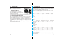
CONTACTS
- DRAPER TOOLS LIMITED,
Hursley Road, Chandler's Ford,
Eastleigh, Hampshire. SO53 1YF. U.K.
-
Helpline: (023) 8049 4344
Sales Desk: (023) 8049 4333
Internet: www.drapertools.com
E-mail: [email protected]
Sales Fax: (023) 8049 4209
General Enquiries: (023) 8026 6355
INSTRUCTIONS FOR
230V Submersible
Water Pumps
Stock Nos.61584, 61621, 61667, 61668
Part Nos.SWP200, SWP170DW, SWP210DW, SWP112
IMPORTANT: PLEASE READ THESE INSTRUCTIONS CAREFULLY TO ENSURE THE SAFE AND
EFFECTIVE USE OF THIS PRODUCT.
- Service/Warranty Repair Agent
For aftersales servicing or warranty repairs, please
contact the Draper Tools Helpline for details of an
agent in your local area.
YOUR DRAPER STOCKIST
Stock No.61667 shown
GENERAL INFORMATION
KCKC260115
These instructions accompanying the product are the original instructions. This document is part of the product, keep it
for the life of the product passing it on to any subsequent holder of the product. Read all these instructions before
assembling, operating or maintaining this product.
This manual has been compiled by Draper Tools describing the purpose for which the product has been designed, and
contains all the necessary information to ensure its correct and safe use. By following all the general safety instructions
contained in this manual, it will ensure both product and operator safety, together with longer life of the product itself.
AlI photographs and drawings in this manual are supplied by Draper Tools to help illustrate the operation of the product.
Whilst every effort has been made to ensure the accuracy of information contained in this manual, the Draper Tools
policy of continuous improvement determines the right to make modifications without prior warning.
1.
TITLE PAGE
NOTES
1.1 INTRODUCTION:
USER MANUAL FOR:
230V SUBMERSIBLE WATER PUMPS
Stock nos. 61584, 61621, 61667, 61668
Part no. SWP200, SWP170DW, SWP210DW, SWP112
1.2 REVISIONS:
Date first published January 2015
As our user manuals are continually updated, users should make sure that they use the very
latest version.
Downloads are available from: http://www.drapertools.com/b2c/b2cmanuals.pgm
DRAPER TOOLS LIMITED
HURSLEY ROAD
CHANDLER’S FORD
EASTLEIGH
HAMPSHIRE
SO53 1YFUK
WEBSITE:
PRODUCT HELPLINE:
GENERAL FAX:
www.drapertools.com
+44 (0) 23 8049 4344
+44 (0) 23 8026 0784
1.3 UNDERSTANDING THIS MANUALS SAFETY CONTENT:
WARNING!
Information that draws attention to the risk of injury or death.
CAUTION!
Information that draws attention to the risk of damage to the product or
surroundings.
1.4 COPYRIGHT © NOTICE:
Copyright © Draper Tools Limited.
Permission is granted to reproduce this publication for personal & educational use only.
Commercial copying, redistribution, hiring or lending is prohibited.
No part of this publication may be stored in a retrieval system or transmitted in any other
form or means without written permission from Draper Tools Limited.
In all cases this copyright notice must remain intact.
2
19
14. DISPOSAL
2.
14.1 DISPOSAL
2.1 CONTENTS
PAGE CONTENT
- At the end of the machine’s working life, or when it can no longer be repaired, ensure
that it is disposed of according to national regulations.
- Contact your local authority for details of collection schemes in your area.
In all circumstances:
• Do not dispose of power tools with domestic waste.
• Do not incinerate.
• Do not abandon in the environment.
• Do not dispose of WEEE*
as unsorted municipal waste.
1
2
3
4
5
* Waste Electrical & Electronic Equipment.
6
7
8
9
10
11
12
13
14
CONTENTS
PAGE
TITLE PAGE
1.1
INTRODUCTION ............................................................................................... 2
1.2
REVISION HISTORY........................................................................................... 2
1.3
UNDERSTANDING THIS MANUAL ................................................................... 2
1.4
COPYRIGHT NOTICE ......................................................................................... 2
CONTENTS
2.1
CONTENTS ........................................................................................................ 3
GUARANTEE
3.1
GUARANTEE ..................................................................................................... 4
INTRODUCTION
4.1
SCOPE ............................................................................................................... 5
4.2
SPECIFICATION ................................................................................................. 5
4.3
HANDLING & STORAGE ................................................................................... 5
HEALTH & SAFETY INFORMATION
5.1
GENERAL SAFETY INSTRUCTIONS .................................................................. 6
5.2
ADDITIONAL SAFETY INSTRUCTIONS FOR SUBMERSIBLE WATER PUMPS.... 8
5.4
CONNECTION TO THE POWER SUPPLY ........................................................... 8
TECHNICAL DESCRIPTION
6.1
IDENTIFICATION ............................................................................................... 9
6.2
MAIN COMPONENT DESCRIPTIONS ................................................................ 10
UNPACKING & CHECKING
7.1
PACKAGING...................................................................................................... 11
7.2
WHAT’S IN THE BOX ........................................................................................ 11
READYING THE PUMP
8.1
INSTALLATION OF PARTS................................................................................. 12
INSTALLING THE PUMP
9.1
PREPARATION AND INSTALLATION ................................................................ 13
9.2
PLACEMENT...................................................................................................... 13
9.3
FLOAT SWITCH ADJUSTMENT ......................................................................... 13
OPERATING THE PUMP ...................................................................................................... 14
10.1 CONNECTING TO POWER VIA RCD ................................................................. 14
10.2 SWITCHING ON THE PUMP .............................................................................. 14
10.3 PUMPING DISTANCES AND VOLUMES ............................................................ 14
TROUBLESHOOTING
11.1 TROUBLESHOOTING CHECKLIST...................................................................... 15
MAINTENANCE
12.1 CLEARING OBSTRUCTIONS FROM IN THE IMPELLER HOUSING..................... 16
12.2 GENERAL MAINTENANCE AND STORAGE ...................................................... 16
EXPLANATION OF SYMBOLS
13.1 EXPLANATION OF SYMBOLS .......................................................................... 17
DISPOSAL
14.1 DISPOSAL ......................................................................................................... 18
DECLARATION OF CONFORMITY .....................................................................................ENCLOSED
18
3
3.
GUARANTEE
3.1 GUARANTEE
Draper tools have been carefully tested and inspected before shipment and are guaranteed
to be free from defective materials and workmanship.
Should the tool develop a fault, please return the complete tool to your nearest distributor
or contact Draper Tools Limited, Chandler's Ford, Eastleigh, Hampshire, SO53 1YF. England.
Telephone Sales Desk: (023) 8049 4333 or Product Helpline (023) 8049 4344.
A proof of purchase must be provided with the tool.
If upon inspection it is found that the fault occurring is due to defective materials or
workmanship, repairs will be carried out free of charge. This guarantee period covering
parts/labour is 12 months from the date of purchase except where tools are hired out when
the guarantee period is ninety days from the date of purchase. This guarantee does not
apply to normal wear and tear, nor does it cover any damage caused by misuse, careless or
unsafe handling, alterations, accidents, or repairs attempted or made by any personnel other
than the authorised Draper warranty repair agent.
Note: If the tool is found not to be within the terms of warranty, repairs and carriage charges
will be quoted and made accordingly.
This guarantee applies in lieu of any other guarantee expressed or implied and variations of
its terms are not authorised.
Your Draper guarantee is not effective unless you can produce upon request a dated receipt
or invoice to verify your proof of purchase within the guarantee period.
Please note that this guarantee is an additional benefit and does not affect your statutory
rights.
Draper Tools Limited.
4
13. EXPLANATION OF SYMBOLS
13.1 EXPLANATION OF SYMBOLS
WEEE
Do not dispose of Waste Electrical
& Electronic Equipment in with
domestic rubbish
17
12. MAINTENANCE
WARNING: For your own safety, remove the plug
from the power supply before maintaining your
submersible water pump.
4.
INTRODUCTION
4.1 SCOPE
12.1 CLEARING OBSTRUCTIONS IN THE
IMPELLER HOUSING – FIG.6
If the impeller becomes blocked or obstructed,
remove the lower housing . By removing the
securing screws .
Remove any foreign objects and then re-fit, making sure
that the rubber sealing o-ring does not get
FIG.6
damaged or pinched in the process.
If at any time the impeller is found to be damaged, have it replaced immediately at your
Draper warranty repair agent.
12.2 GENERAL MAINTENANCE AND STORAGE
Flush your pump through with fresh clean water from time to time if it is left idle in water
for some time.
Draper recommends that if the pump is not to be used for some time that the pump is
removed from the water. It should be flushed through with fresh clean water to remove any
dirty water that may remain inside the pump. Clean the outside of the pump and dry with a
cloth before storing the pump ready for its next use.
You should always perform a visual check of the pump prior to storing and re-using so that
any wear or damage to the pump or its power supply cable can be safely rectified prior to
next use.
The pump should be protected from frost, do not allow any residual water to freeze inside
the pump as irreversible damage will occur.
This instruction booklet covers two 230V submersible dirty water pumps, which ideally suited
for general irrigating, draining inspection pits, trenches and footings where solids may be
present. Maximum solid passable by the dirty water pumps is 30mm.
Also covered by these instructions is two clear water pump, ideally suited for pumping clear
water from pools and garden ponds where the water is free of debris. However, this pump
also has the capabilities of passing solids of up to 3mm.
4.2 SPECIFICATION
Stock No:..................... 61584 .........................61621......................... 61667......................... 61668
Part No:..................... SWP200...................SWP170DW............... SWP210DW .................. SWP112
Pump Usage: ......... Clear Water................Dirty Water .............. Dirty Water................Clear Water
Float Switch: ..................Yes ..............................Yes............................. Yes ............................. Yes
Motor:
Rated voltage: ........ 230V .......................... 230V .......................... 230V........................... 230V
Rated
frequency:............... 50Hz .......................... 50Hz ..........................50Hz...........................50Hz
Rated
input:...................... 550W..........................550W......................... 750W ......................... 350W
Max. particle size: ....... 3mm ........................ 30mm* ...................... 30mm*......................... 3mm
Output
aperture size: ...... 25mm, 32mm............ 25mm, 32mm ............25mm, 32mm ............25mm, 32mm
(stepped adaptor)
(stepped adaptor) (stepped adaptor) (stepped adaptor)
Max. flow rate:.........191L/min ....................166L/min................... 200L/min ................... 108L/min
Max. head height: ...... 9.5M .......................... 8.5M ..........................9.5M............................ 7M
Max. operating
depth: ............................5M .............................. 5M............................. 5M ............................. 5M
Max. water
temperature: ................35°C ............................35°C........................... 35°C ........................... 35°C
Min water level for
operation:................... 80mm ....................... 130mm ......................130mm........................80mm
Float switch
cut-in height:............. 380mm ...................... 410mm ...................... 410mm.......................380mm
Float switch
cut-out height ........... 170mm ...................... 200mm ......................200mm.......................170mm
Power cable length:.....10M ............................10M........................... 10M ........................... 10M
Weight: ...................... 4.89kg ......................... 5kg ..........................6.19kg ....................... 4.69kg
Degree of protection
against moisture: .........IPX8 ............................ IPX8........................... IPX8 ........................... IPX8
Warning: These products must be used in conjunction with a residual current device (RCD)
4.3 HANDLING & STORAGE
This submersible pump is designed to be moved to different locations. Ensure it is always
operated on a level surface.
*Note: Max particle size of 30mm requires the 25mm section of hose barb to be removed/cut
off to reveal 32mm bore.
16
5
5.
HEALTH & SAFETY INFORMATION
5.1 GENERAL SAFETY INSTRUCTIONS
General Power Tools Safety Warnings
WARNING: Read all instructions. Failure to follow all instructions listed below may result
in electric shock, fire and/or serious injury.
Save all warnings and instructions for future reference.
The term “power tool” in the warnings refers to your mains operated (corded) power tool or
battery operated (cordless) power tool.
1) Work area safety
a) Keep work area clean and well lit. Cluttered or dark areas invite accidents.
b) Do not operate power tools in explosive atmospheres, such as in the presence of
flammable liquids, gases or dust. Power tools create sparks which may ignite the
dust or fumes.
c) Keep children and bystanders away while operating a power tool. Distractions can
cause you to lose control.
2) Electrical Safety
a) Power tool plugs must match the outlet. Never modify the plug in any way. Do not
use any adapter plugs with earthed (grounded) power tools. Unmodified plugs and
matching outlets will reduce risk of electrical shock.
b) Avoid body contact with earthed or grounded surfaces such as pipes, radiators,
ranges and refrigerators. There is an increased risk of electric shock if your body is
earthed or grounded.
c) Do not expose power tools to rain or wet conditions. Water entering a power tool
will increase the risk of electric shock.
d) Do not abuse the cord. Never use the cord for carrying, pulling or unplugging the
power tool. Keep cord away from heat, oil, sharp edges or moving parts. Damaged or
entangled cords increase the risk of electric shock.
e) When operating a power tool outdoors, use an extension cord suitable for outdoor
use. Use of a cord suitable for outdoor use reduces the risk of electric shock.
f) If operating a power tool in a damp location is unavoidable, use a residual current
device (RCD) protected supply. Use of an RCD reduces the risk of electric shock.
3) Personal Safety
a) Stay alert, watch what you are doing and use common sense when operating a
power tool. Do not use a power tool while you are tired or under the influence of
drugs, alcohol or medication. A moment of inattention while operating power tools
may result in serious personal injury.
b) Use personal protective equipment. Always wear eye protection. Protective
equipment such as dust mask, non-skid safety shoes, hard hat, or hearing protection
used for appropriate conditions will reduce personal injuries.
c) Prevent unintentional starting. Ensure the switch is in the off position before
connecting to power source and/or battery pack, picking up or carrying the tool.
Carrying power tools with your finger on the switch or energising power tools that
have the switch on invites accidents.
d) Remove any adjusting key or wrench before turning the power tool on. A wrench or
a key left attached to a rotating part of the power tool may result in personal injury.
e) Do not overreach. Keep proper footing and balance at all times. This enables better
control of the power tool in unexpected situations.
6
11. TROUBLESHOOTING
11.1 TROUBLESHOOTING CHECKLIST
No power
1. Faulty power supply.
2. Power supply fuse
blown.
3. Residual current circuit
breaker tripped.
1. This should be replaced
immediately by a qualified
person.
2. Replace the fuse.
3. Check and reset.
Pump running,
but not delivering
water.
1. Water level under the
minimum pumping level.
2. Filter inlet clogged.
3. Outlet tube clogged.
4. Hose flat.
1. Raise the water level (where
possible).
2. Clean inlet.
3. Remove tube and clear
obstruction.
4. Re-install the pump, but at an
angle, when submerged, gently
shake while outlet tube is open.
Switch on/off repeatedly.
Pump stops
running due to
thermal overload
coming into
operation.
1. Voltage supply different
to rating plate.
2. A solid has jammed in
pump.
3. The pump is operating
in hot water.
4. The pump ran dry.
1. Remove plug from power supply.
2. Remove obstruction.
3. Allow pump to cool then restart.
4. Wait for pump to cool then
submerge before switching on.
15
5.
10. OPERATING THE PUMP
Once you have the pump safely situated and the float
switch adjusted, if required, you are ready to turn on the
pump.
FIG.3
10.1 CONNECTING TO POWER VIA RCD – FIG.3
Plug your pump into a Residual Current Device (RCD)
such as Draper Stock No.69307 or 89301 and
connect to your mains supply.
RCD’s sold separately
10.2 SWITCHING ON THE PUMP – FIG.4
On switching on your socket, the pump will begin to
operate (if water level high enough to operate the float
switch). The pump will begin to expel the water via your
hose and once the water level drops to the required
level, the float switch will automatically switch off
the pump.
*Note. Stock No.61668 is not supplied with a float switch.
10.3 PUMPING DISTANCE AND VOLUME – FIG.5
Fig.6 provides a guide for volumes pumped in relation to
hose height.
Horizontal pumping distance is directly affected by the
working head height (Maximum head height minus
actual working head height × factor of 10 equals the
approximate horizontal pumping distance in metres
using solid delivery hose).
For example:
Model SWP200 maximum head height is 9.5 metres,
minus actual working head height of 5 metres = 4.5
metre × factor of 10 is 45 metres (approximate pumping
distance).
14
FIG.4
FIG.5
25L/min
5M
55L/min
3M
80L/min
1.5M
HEALTH & SAFETY INFORMATION
f) Dress properly. Do not wear loose clothing or jewellery. Keep your hair, clothing and
gloves away from moving parts. Loose clothes, jewellery or long hair can be caught in
moving parts.
g) If devices are provided for the connection of dust extraction and collection facilities,
ensure these are connected and properly used. Use of dust collection can reduce dust
related hazards.
4) Power Tool Use And Care
a) Do not force the power tool. Use the correct power tool for your application. The
correct power tool will do the job better and safer at the rate for which it was
designed.
b) Do not use the power tool if the switch does not turn it on and off. Any power tool
that cannot be controlled with the switch is dangerous and must be repaired.
c) Disconnect the plug from the power source and/or the battery pack from the power
tool before making any adjustments, changing accessories, or storing power tools.
Such preventive safety measures reduce the risk of starting the power tool
accidentally.
d) Store idle power tools out of the reach of children and do not allow persons
unfamiliar with the power tool or these instructions to operate the power tool.
Power tools are dangerous in the hands of untrained users.
e) Maintain power tools. Check for misalignment or binding of moving parts, breakage
of parts and any other condition that may affect the power tools operation. If
damaged, have the power tool repaired before use. Many accidents are caused by
poorly maintained power tools.
f) Keep cutting tools sharp and clean. Properly maintained cutting tools with sharp
cutting edges are less likely to bind and are easier to control.
g) Use the power tool, accessories and tool bits etc., in accordance with these
instructions, taking into account the working conditions and the work to be
performed. Use of the power tool for operations different from intended could result
in a hazardous situation.
5) Battery tool use and care
a. Recharge only with the charger specified by the manufacturer. A charger that is
suitable for one type of battery pack may create a risk of fire when used with another
battery pack.
b. Use power tools only with specifically designated battery packs. Use of any other
battery packs may create a risk of injury and fire.
c. When battery pack is not in use, keep it away from other metal objects, like paper
clips, coins, keys, nails, screws or other small metal objects, that can make a
connection from one terminal to another. Shorting the battery terminals together
may cause burns or a fire.
d. Under abusive conditions, liquid may be ejected from the battery; avoid contact. If
contact accidentally occurs, flush with water. If liquid contacts eyes, additionally seek
medical help. Liquid ejected from the battery may cause irritation or burns.
6) Service
a. Have your power tool serviced by a qualified repair person using only identical
replacement parts. This will ensure that the safety of the power tool is maintained.
7
5.
HEALTH & SAFETY INFORMATION
5.2 ADDITIONAL SAFETY INSTRUCTIONS FOR SUBMERSIBLE WATER PUMPS
–
When carrying or lifting the submersible pump always use the transport handle, DO NOT
carry or lift using the power cable or float switch cable.
– Before connecting to the power supply:
• A residual current circuit breaker (RCD) must be used for all applications
(Draper Stock No.69307 or 89301).
• The electrical supply should be the same as that stated on the rating plate.
– Submersible water pumps should always be transported, stored, and submersed vertically.
– Always ensure that your hands are dry when connecting and disconnecting the power
supply.
– Never operate the pump below the top of the water inlet.
– The area being pumped should be kept clear, and nobody should enter the area while
pump is operating.
– Do not pump explosive or flammable liquids.
Important: please read before use.
The following additional instructions must be followed at all times. Failure to do so could
invalidate the guarantee of this submersible water pump.
– The float switch must be clamped in position using the cable clamp recess.
NOTE: The pump, should be suspended using a rope, chain or stood on a brick to prevent
any gravel etc. being sucked into the pump and damaging the impeller.
– If the pump fails to operate, disconnect from mains supply. Remove the base (see page 9)
and gently turn the impeller using a screwdriver. Check for obstruction in the impeller,
i.e. stones/gravel etc.
– The float switch fitted to the pump is NOT suitable for continuous use as an ON/OFF
switch.
– If the power cable becomes damaged it must be changed by the manufacturer or it’s
service agents.
IMPORTANT: Any pump returned to Draper Tools Limited under warranty must be clean. If a
pump is received that has NOT been cleaned, it will be returned to you at your cost.
Make sure the power supply information on the machine’s rating plate are compatible with
the power supply you intend to connect it to.
5.3 CONNECTION TO THE POWER SUPPLY
This machine comes supplied with a UK standard 3 pin plug fitted. It is designed for
connection to a domestic power supply rated at 230V AC.
This product is a Class 1 machine; meaning, it must have an earth connection in the power
supply. This is to prevent electrocution in the event of a failure.
Apart from replacing the fuse in the plug, no other electrical work is recommended on this
machine.
8
9.
INSTALLING THE PUMP
9.1 PREPARATION AND INSTALLATION
WARNING: DO NOT MAKE ANY OF THE FOLLOWING ADJUSTMENTS WITH THE PUMP
CONNECTED TO THE POWER SUPPLY.
CAUTION: Whilst the two dirty water submersible water pumps (Stock Nos.61621 and 61667)
covered in these instructions are all capable of passing suspended solids of varying size, it is
important to check the maximum particle size listed in the specification section on page 5 for
your own particular model.
The clear water submersible pumps (Stock Nos.61584 and
61668) are designed to pump clear water only. Ensure all
loose stones/gravel etc. are removed from water prior to
using this pump. Ingestion of solids larger than 3mm will
cause damage to the pump.
9.2 PLACEMENT – FIG.1
This pump must be placed on a stable level surface away
from any loose stones or other objects that could get
sucked into the pump accidentally.
FIG.1
FIG.2
9.3 FLOAT SWITCH ADJUSTMENT – FIG.2
(Stock Nos.61584, 61621 and 61667 only).
Once the pump has been located on a suitable surface,
you can choose to adjust the height at which the float
switch operates to switch on/off the pump. To adjust
the height at which the float switch operates you will
need to clip the connecting cable of the float switch into the moulded-in clamp in the
side of the pumps carry handle , allowing the required amount of travel for the float
switch to operate the pump at your required water levels.
Connect your lay flat hose to the pumps outlet and route your hose to your required
destination. Ensure that all hose connections are secure before proceeding.
CAUTION: This pump is not designed to be used in any ‘continuous running’ applications such
as water circulation (water features, etc.). To do so would invalidate the pumps warranty.
13
8.
READYING THE PUMP
8.1 INSTALLATION OF PARTS
6.
TECHNICAL DESCRIPTION
6.1 IDENTIFICATION
Before first use it is important to carry out a visual check of the product to ensure that the
product has not suffered any transit damage and is safe to use.
To connect the hose adaptor, simply screw it into its threaded housing.
To adjust the stepped hose adaptor for your chosen size of lay flat hose, check the internal
dimensions of your lay flat hose and select either the 25 or 32mm section of the stepped
adaptor to connect your hose to. To gain the full benefit of the increase in flow rate that can
be achieved with the larger hose/stepped adaptor apertures it will be necessary to remove
the unused smaller section of the stepped adaptor (see page 11) and this is best
accomplished with a small hacksaw sawing through the threaded area will reveal the 32mm
bore (applicable to 61621, 61667 models only).
NOTE: The adaptor can now only be used with a 32mm hose and cannot be used with a
25mm hose.
25mm adaptors are available, quote Stock No.62877.
Your chosen hose should be secured with a suitable retaining clip. The float switch should be
allowed to move freely without any restrictions. The float switch can be set to turn the pump
on/off at differing water levels, this will be covered in the following section of this manual.
Stock No.61667 shown
Water inlet/impeller housing
10M power cable
Carry handle
Stepped adaptor
Outlet
Float switch
(Excludes Stock No.61668)
Main pump body/motor housing
12
9
6.
TECHNICAL DESCRIPTION
7.
UNPACKING & CHECKING
6.2 MAIN COMPONENT DESCRIPTIONS
7.1 PACKAGING
The CARRY HANDLE for ease of transportation.
Carefully remove the pump from the packaging and examine it for any sign of damage
that may have happened during shipping. Lay the contents out and check them against the
parts shown below. If any part is damaged or missing; please contact the Draper Helpline
(the telephone number appears on the Title page) and do not attempt to use the pump.
The packaging material should be retained at least during the guarantee period: in case
the machine needs to be returned for repair.
Warning! Some of the packaging materials used may be harmful to children. Do not leave
any of these materials in the reach of children.
If any of the packaging is to be thrown away, make sure they are disposed of correctly;
according to local regulations.
The STEPPED HOSE ADAPTOR allows the use of 25 and 32mm hoses.
The WATER OUTLET; Pumped water is expelled from this aperture.
The PLUG connects the machine to your power supply.
The FLOAT SWITCH (Excluding Stock No.61668) will switch the pump on/off automatically
at set water levels (user adjustable).
The MAIN PUMP BODY houses the pumps motor, it should be submerged in use to help
cool the motor.
7.2 WHAT´S IN THE BOX?
As well as the pump; there may be several parts not fitted or attached to it.
The INLET/IMPELLER HOUSING; This is where the water to be pumped enters the machine.
The impeller is mounted in the top section of the housing.
25mm
32mm
Outlet.
Stepped 25mm/32mm output adaptor.
Applicable to 61621 and 61667 models only.
Cut off 25mm section at dotted line to use full
32mm bore option. (32mm layflat hose must be
used).
10
11