1
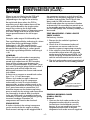
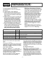
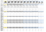
FAULT CODE READER
■ STOCK No.54732
■ PART No.FCR
• INSTRUCTIONS •
IMPORTANT: PLEASE READ THESE INSTRUCTIONS CAREFULLY TO ENSURE
THE SAFE AND EFFECTIVE USE OF THIS TOOL.
01/2000
FAULT CODE READER
■ STOCK No.54732
CONTENTS:
■ PART No.FCR
Page No.
Declaration of Conformity ................................................................................1
Introduction......................................................................................................2
Safety Warning .................................................................................................3
Instructions..................................................................................................3-10
DECLARATION OF CONFORMITY
We
Draper Tools Ltd. Hursley Road, Chandler’s Ford, Eastleigh, Hampshire.
SO53 1YF. England.
Declare under our sole responsibility that the product:
Stock Number:- 54732.
Part Number:- FCR.
Description:- Fault Code Reader.
To which this declaration relates is in conformity with the following directive(s)
98/37/EC, 72/23/EEC & 89/336/EEC.
With reference to:
EN50144, EN55014, EN61000-3-2 & EN61000-3-3.
JOHN DRAPER
Managing Director
09/99
INTRODUCTION
output after the codes for any present faults
but Vauxhall codes are all output together
(both present and past stored codes).
Nearly all engines found in modern vehicles
are fitted with a number of sensors and an
Electronic Control Unit, which is often
referred to as an ECU.
The function of the engine sensors is to
constantly send information to the electronic
control unit (ECU) which monitors the
performance of various areas of the engine.
The ECU then analyses the information it
has received and determines whether the
values are within the manufacturer’s
permitted specifications/tolerances, minor
changes in value can be compensated for
by the ECU. For example it can adjust/
determine the correct injection duration.
However, if the ECU receives information
from a sensor and the value is outside the
manufacturer’s permitted
specifications/tolerances then the ECU will
recognise this as a fault as it is fitted with a
pre-programmed self-diagnosis system.
The ECU will then store the corresponding
code in its memory for retrieval at a later
date and in some cases will set the
corresponding code in its memory for
retrieval at a later date and in some cases
will set itself to run on a pre-programmed
emergency backup value otherwise known
as ‘mapping’. This allows the vehicle to be
driven to a garage or home etc. for fault
diagnosis and repair.
With use of a fault code reader the user can
read fault codes that are present at the time
of testing and the codes stored in the
memory of the ECU then referring to the
appropriate fault code reference tables the
fault can be located quickly and accurately.
These stored fault codes are output at
different times depending on the vehicle
make and model, i.e. stored Ford codes are
The fault codes output from different
manufacturers are not the same and the
appropriate fault code reference table for
the particular vehicle must be referred to,
for instance, Ford vehicles output two or
three digit codes whereas Audi vehicles
output four digit codes. In most cases the
codes will be displayed and read via the
fault code reader itself, however some
vehicles (Vauxhall) will be read by the fault
code reader but displayed via the vehicle’s
instrument panel.
Vehicles fault code diagnostic sockets differ
from manufacturer to manufacturer and this
code reader is supplied complete with
leads suitable for connection to Ford and
Vauxhall vehicles.
NOTE: The Ford adaptor lead supplied is
suitable for use with the EEC-IV ECU.
Once all faults have been located and
rectified the fault codes can be erased from
the ECU memory. On some vehicles this is
carried out using the fault code reader but
others, such as Vauxhalls, the power supply
fuse to the ECU must be removed, or the
negative terminal on the battery
disconnected for approximately one minute.
NOTE: If the battery terminal is
disconnected other items such as radio,
alarms etc. will need to be reset. ENSURE
you have the relevant codes to reset them. If
the codes cannot be erased as above then
they will automatically be erased after
approximately 20 cold starts (from cold to
normal engine temperature).
-3-
SAFETY WARNING
Please read the following instructions
carefully, failure to do so could lead to
personal injury or damage to the vehicle.
1. Avoid a dangerous environment.
Do not expose the fault code reader to
rain, ensure the work area is well lit.
Always store the code reader in its case
when it is not in use.
3. Never leave the code reader switched
ON in a testing mode or when the code
reader is switched ON and carrying out
test procedures. Always switch the code
reader and vehicle’s ignition off first.
4. Never leave the vehicle with the engine
running – always switch the engine off
before leaving the vehicle.
2. When using this code reader on a vehicle
it may involve carrying out tests with the
engine running and the following points
should be followed to avoid injury.
5. Ensure the code reader is secure before
starting any testing preferably attaching
it to a body panel using the magnetic
strip on the rear of the code reader.
a) Wear proper clothing – do not wear loose
clothing, neckties (rings, wrist watches)
which could catch in moving parts. Non
slip footwear is recommended.Wear a
protective hair covering to contain long
hair. Roll long sleeves above the elbow.
6. Check that all cables are kept clear of
hot/moving parts.
b) Do not over-reach – keep proper footing
and balance at all times.
7. Only run the engine in a well-ventilated
area. Do not inhale exhaust gases, as they
are dangerous and can be fatal. Never
run the engine in a garage or other
confined area.
INSTRUCTIONS FOR USE
FORD VEHICLES
INTRODUCTION
This fault code reader is supplied complete
with an adaptor lead for use with the Ford
EEC-IV electronic control unit, Ford’s fourth
generation of electronic engine control unit.
This particular model of ECU unit was first
introduced in 1985 and was used in all EFI
engine vehicles from 1988/89 and almost all
petrol engine Ford vehicles from 1991/2.
There are several versions of the EEC-IV, the
earlier versions used a 2-digit code system
of which there were two types of coding. The
later versions of the EEC-IV use a 3-digit
code system.
Refer to the Haynes Techbook supplied for
further details on your vehicle.
-4-
INSTRUCTIONS FOR USE –
FORD VEHICLES (Cont’d.)
SELF-TEST/FAULT CODE READOUT
SOCKET
Most Ford vehicles fitted with the EEC-IV
electronic control unit are equipped with a
self-test/fault code readout socket.
This socket has a black body with a red
protective cap which can be removed to
reveal the connector pins. The socket will be
found in the engine compartment near to the
bulkhead or battery. For more detailed
information on where to find the socket refer
to Haynes diagnostic fault codes manual
supplied.
CONNECTING THE FAULT CODE
READER TO THE SELF-TEST/FAULT
CODE READOUT SOCKET
The Ford EEC-IV adaptor lead used to
connect the fault code reader to the self
test/fault code read out socket is supplied.
Profile of Ford adaptor
(plan view)
Connect the adaptor lead to the fault code
reader via the 5-pin din type connector.
IMPORTANT: Before connecting the fault
code reader to the self test/fault code
readout socket ensure that a good battery is
fitted to the code reader, the vehicle’s
handbrake is applied, neutral (manual
transmission) or ‘P’ (automatic transmission)
is selected, ignition switched off, air
conditioning (where fitted) and any other
electrical loads, i.e. lights, fans etc. must all
be turned OFF.
Check that the code reader is switched off
and in the standby position. Now connect the
fault code reader to the vehicle’s read out
socket.
READING/UNDERSTANDING
OUTPUT CODES
Once the code reader is connected to the
ECU and in the test mode the ECU will send
coded pulses to the fault code reader which
are then output by the fault code reader to
the user in two ways – (a) audible (bleep),
and (b) visual (blink) by the fault code
indicator. (See table on page 5).
The user simply counts the beeps or blinks
which are output from the FCR to identify
particular numbers/codes, i.e. number 3
would be output as three rapid pulses, so the
user would hear three rapid bleeps and at
the same time the fault code indicator would
blink rapidly three times, indicating number
3. Number 8 would be output as eight rapid
pulses, so the user would hear eight rapid
bleeps and at the same time the fault code
indicator would blink rapidly eight times
indicating number 8.
2-DIGIT NUMBERS
When reading a two digit number i.e. 69 the
number will be output in two parts, first
there would be six rapid bleeps/blinks then
a short pause followed by nine further rapid
bleeps/blinks indicating 69.
3-DIGIT NUMBERS
This is very similar to reading 2 digit code
numbers but the number will be output in
three parts instead of two, i.e. 193 would be
output as follows: first there would be one
bleep/blink, a short pause, then nine rapid
bleeps/blinks, a short pause then a further
three bleeps/blinks indicating 193.
-5-
INSTRUCTIONS FOR USE –
FORD VEHICLES (Cont’d).
When in use it is likely that the FCR will
output several 2 or 3 digit fault codes
(depending on the age of the vehicle).
the connector/wiring is at fault this will be
evident by the engine’s response as contact
is broken and remade. The FCR will also
bleep and the LED indicator will be
illuminated when the connection is broken
and remade. If the standby/test switch is set
to the standby position during the wiggle
test all KAM (keep alive memory codes) will
be erased.
As explained above when the FCR is
outputting say 2 digit codes there will be
short pauses between the single codes
output that make up the 2 digit code
number. However, when it is outputting more
than one 2 digit code there will be much
longer pauses between the full output
codes.
Example: code output 23 followed by 48:
Two rapid bleeps/blinks indicating 2, a short
pause then three rapid bleeps/ blinks
indicating 3 = 23. This would then be
followed by a longer pause then four rapid
bleeps/blinks indicating 4, a short pause
then eight rapid bleeps/blinks indicating 8
= 48.
GENERAL
When the fault code reader is outputting
current fault codes and any previously
stored fault codes from the ECU memory
there will be a long pause between the
current and stored codes, or the code 1 may
be heard. This single bleep/blink is called a
separator code which helps the user
distinguish between the current and stored
fault codes.
If there are no current or stored fault codes
then 11 or 111 will be output.
When a fault code is output it does not
necessarily mean that the component
indicated is at fault. The fault could be
generated by another problem such as the
component connector or wiring is faulty or
has a poor/intermittent connection. It is
therefore important that before replacing
parts or units that the wiring and connectors
are thoroughly checked. Also if multiple
faults are indicated it is possible these are
caused by a fault on one component giving
incorrect readings. Therefore all
components will need to be checked.
WIGGLE TEST
A further check of the wiring/connectors
can be made whilst the engine is idling.
Each sensor’s wiring can be wiggled and if
TEST PROCEDURE – FORD 2-DIGIT
FAULT CODES
Preliminary checks:
1. Ensure that the vehicle’s ignition is
switched off.
2. Check that all the sensor leads and
connectors are secure and that the
breather system is operating correctly.
3. If the vehicle is fitted with grounded
octane/idle adjust wires the plug and
socket must be disconnected (Fig.1). To
locate this plug and socket refer to the
vehicle manufacturer’s service manual.
4. The fault code reader must be switched off
and the test switch in the standby position.
Fig.1
Ford octane/idle white
socket when connected
(as seen in vehicle)
TESTING/READING CODES
(FORD 2-DIGIT)
General
1. Connect the fault code reader to the
diagnostic socket which is normally
located near the bulkhead near the
battery. If you are unable to locate the
diagnostic socket refer to Haynes
diagnostic fault codes manual supplied.
-6-
INSTRUCTIONS FOR USE –
FORD VEHICLES (Cont’d.)
2. Switch the fault code reader on.
It is now possible to carry out various test
procedures:
A. Ignition ON – engine OFF test
1. Turn the ignition to the ON position but
do not start the vehicle. Have a piece of
paper and a pen available to write down
output codes.
2. Now to start the test push the standby/start
switch to the start position and wait up to
one minute for the codes to be output.
During this time ignore any rapid pulses,
you may also hear/see sensors starting/
stopping/moving – this is part of the OBD
(on board diagnostics) carrying out tests.
3. Next the fault code reader will output
codes as explained previously. The codes
will be output in the following order:
current fault codes, then stored fault
codes sometimes referred to as KAM
(keep alive memory) codes. Note the
CODE TYPE
Current code
Current code (repeated)
Separator code
Stored KAM codes
Stored KAM codes (repeated)
Test completed
CODE
NO.
11
11
2
11
11
1
KAM (keep alive memory) will output
both current and stored fault codes when
read. There is a pause between the codes
output and a longer pause between the
present (current) and stored codes. On
some systems code 2 will be output
between the current and stored codes to
help distinguish between them. This is
known as a separator code. The codes
output will be repeated after a short
delay and the end of the test will be
indicated by code number 1.
3. If no faults are found the code 11 will be
output. After the code 1 has been output
(indicating the end of the test) the OBD
(on board diagnostic system) will be
ready to start the wiggle test – refer to
page 7.
3. For example, if there are no current or
stored codes the following codes will be
output. 11, 11, 2, 11, 11, 1. Meaning:
MEANING
No current codes
No current codes
Separator code. Separates the stored KAM codes & the
current fault codes
No stored codes
No stored codes
Ready to start wiggle test
However, if for instance the output codes
were:
11, 11, 2, 17, 17, 1
it would mean that there are no current fault
codes but fault code 17 has been recorded
sometime in the past and stored in the keep
alive memory (KAM).
If the output codes were:
22,30,39, 22,30,39, 2, 22,30,39,50, 1
it would indicate that faults 20, 30 and 39 are
currently existing and fault 50 has been
recorded sometime in the past and stored in
the keep alive memory (KAM).
Now the fault codes have been identified
refer to the Haynes manual supplied.
The codes stored in the KAM can be kept or
erased. To erase the codes simply switch the
standby/start switch to the standby position.
To keep the stored codes turn the vehicle’s
ignition off before switching the code reader
to standby.
B. Engine running test
Note: Before commencing the engine
running tests run the engine until it reaches
normal operating temperature (if air
conditioning is fitted to the vehicle switch it
off). If the fault code reader is switched to
‘start test’ before the engine has reached
normal operating temperature the test will
not start until normal operating temperature
has been reached.
-7-
INSTRUCTIONS FOR USE –
FORD VEHICLES (Cont’d.)
1. Connect the fault code reader to the
diagnostic socket as described earlier
and switch it ON. Now put the
standby/start switch to the ‘start’ position.
2. Start the vehicle’s engine. (If any rapid
bleeps are heard this is just the OBD
starting its test procedure.When used with
some vehicles code 5 may be output and
this indicates that the engine running test
has started. The engine RPM (speed) will
increase to approximately 2500 RPM for up
to one minute then return to normal.
3. If code 2 is output carry out the following
procedure:
a. Fully depress the brake pedal.
b. If the vehicle is fitted with power
steering turn the steering wheel to full
lock one way then centre it again. (This
should send a signal from the power
steering pressure switch to the ECU. If
no signal is received then code 521
will be output).
c. If the vehicle is fitted with automatic
transmission press the override button
on, then off. Now do the same for the
sport/economy switch (where fitted).
d. Wait for the code reader to output
separator code 1. Then fully depress
the accelerator pedal and release it
again. Engine running test codes will
now be output and all of these are
repeated once. If no faults are found or
present code 11 will be output as
follows: 11, 11, 6.
Code 6 indicates the engine running
tests have been completed and the
ECU is entering its service adjustment
programme. This programme lasts for
approximately two minutes.
SERVICE MODE
During the service mode the idle speed
control valve is de-activated and the idle
speed is set to its pre-programmed value. At
this point it is possible to check and reset
other basic settings (refer to vehicle
manufacturer’s service manual). These
adjustments cannot be made at any other
time, as the ECU would not allow it. For a
vehicle’s service mode data refer to Haynes
diagnostic fault codes manual supplied.
The end of the service mode will be
indicated in one of several ways:
a. The engine speed briefly increases and
returns to normal as the idle speed
control is re-activated.
b. If code 5 was output earlier then code 6
or 7 will be output at the end of the
service mode. If adjustments etc. have not
been completed by the end of the service
mode the engine on test should be
repeated and the adjustments can then
be completed.
NOTE: Single digit codes transmitted i.e. 1,
6, 9 etc. can be referred to in the
manufacturer’s service manual as 10, 60, 90
etc.
CONTINUOUS TEST MODE
NOTE: Before commencing the engine
running tests the engine should be run until
normal operating temperature is reached. (If
air conditioning is fitted to the vehicle it
must be switched off). If the fault code
reader is switched to the ‘start’ position
before the engine has reached normal
operating temperature the test will not start
until normal operating temperature has
been reached.
1. Connect the FCR to the diagnostic socket.
2. Ensure the FCR is switched on and in the
standby position.
3. Start the engine.
4. Switch the FCR to the ‘start’ position. Any
existing fault codes will now be
transmitted and repeated continuously. At
this time it is possible to carry out a
‘wiggle test’ whereby various connectors
can be checked as described earlier. Any
fault codes will then be output. If no faults
are present the code 11 will be output.
-8-
INSTRUCTIONS FOR USE –
FORD VEHICLES (Cont’d.)
end of the engine running tests it is possible
to carry out a power balance test, enter the
service mode or switch off the ignition and
set the FCR to the ‘standby’ position.
ERASING FAULT CODES FROM THE KAM
The KAM (keep alive memory) can be
erased in two ways.
Either:
a. By disconnecting the battery – however
other memories will be lost such as radio
and clock. Or:
b. Follow the ignition on-engine off test
described earlier and at the end of the
test procedures set the test/standby
switch to the standby position.
RELAY TEST
All relays and solenoids (except fuel pump
and fuel injector) can be checked during
this test.
This test should be started at the end of the
‘ignition on – engine off test’ and is started
by depressing the throttle pedal fully and
releasing it again. This will switch all the
relays and solenoids ‘ON’.
Fully depressing the throttle pedal again
and releasing will de-activate the relays and
solenoids.
3-DIGIT SYSTEMS
The Ford 2 and 3-digit systems are very
similar to each other, the obvious difference
being that the codes output on 2-digit
systems are 2 digit and 3-digit systems
output 3 digit codes.
The codes output are read in the same way
as the 2-digit system. For example, the no
fault found code in 111 therefore if there are
no current fault codes and no stored fault
codes in the KAM memory then the codes
output would be as follows:
111, 111, 1, 111, 111.
If the codes output were: 111, 111, 1, 182, 182
it would indicate that there are no current
fault codes but code 182 (meaning the idle
mixture is too lean) has been stored in the
KAM at some time.
If the codes were: 182, 182, 1, 332, 332 it
would indicate that the idle mixture is too
lean (code 182) and that the EGR valve has
not been opening (code 332) and this code
has been stored in the KAM memory.
POWER BALANCE TEST
This test is started at the end of the ‘engine
running test’.
To start the test the engine RPM should be
increased above 3000 RPM for
approximately five seconds. Then release
the throttle and the engine RPM will stabilise
at around 1500 RPM.
The OBD will then start the test and will cut
the spark to each cylinder in turn. As the
spark is cut to each cylinder there will be a
drop in the engine speed, a weak or faulty
cylinder will not effect the engine speed as
much as a strong cylinder, and if a cylinder
is not working at all then the engine speed
will not be effected at all. However, it may
not be the cylinder itself which is at fault but
a faulty injection system or ignition.
At the end of this test and all cylinders are
equally balanced code 9 will be output. If
any cylinder is weak then code number 1-8
will be output indicating which cylinder is
not functioning correctly.
IGNITION ON – ENGINE OFF TESTS
Refer to ignition on – engine off tests in the
Ford 2-digit section.
ENGINE RUNNING TESTS
Refer to the instructions for Ford 2-digit code
systems, however, please note that once the
test has started the OBD will transmit an
identification code which corresponds with
the number of cylinders. Code 2 indicates a
4-cylinder engine; code 3 indicates a
6-cylinder engine.
After this code is output refer to 3a of engine
running tests (Ford 2-digit systems). At the
SERVICE MODE
Refer to ‘service mode’ in Ford 2-digit
systems section.
ERASING FAULT CODES
Refer to ‘erasing fault codes’ in the Ford
2-digit systems section.
-9-
INSTRUCTIONS FOR USE –
GM/VAUXHALL/OPEL
Engine management systems fitted to
Vauxhall vehicles are mainly of Bosch or
GM-multec origin including Bosch
Motoronic and GM multec MPi and SPi.
Other systems include Simtec and Bosch E2Plus.
Each of the above ECU has a different
system of on board diagnostics and fault
code recording. However, other than
different output codes the units are similar.
The self diagnosis connector will be found
on most Vauxhall vehicles either under the
facia in the passenger compartment fuse
box or in the engine compartment near to
the fuse box. (Refer to the Haynes manual
supplied with the fault code reader for
further details). Note there are two types of
connector plug fitted to Vauxhall vehicles
and the connector plug supplied with the kit
is suitable for both socket types.
The codes output are identified the same
way as the Ford codes – by counting the
number of flashes. Refer to page 6 of this
manual for further details.
However instead of counting the flashes
output on the fault code reader the codes
will be flashed on the ‘check engine’ light on
the dashboard. All codes will be displayed
three times. If code 12 is displayed then this
indicates no faults.
TESTING PROCEDURE
1. Turn inginition off.
2. Connect the FCR to the diagnostic socket
using the Vauxhall adaptor supplied in
the kit.
3. Check that the FCR test switch is set to
standby.
4. Turn on ignition but do not start the
engine.
5. Set the test switch to the start position.
6. Write down the codes output from the
‘check engine’ indicator light on the
dashboard.
7. Once you have identified the code
numbers refer to the fault code tables
listed in the Haynes manual supplied with
this kit.
8. To stop the codes being output set the
test switch to the standby position, turn
off the ignition and disconnect the code
reader.
ERASING FAULT CODES
Fault codes can be erased from the ECU if
necessary – refer to the Haynes service
manual supplied with this kit for further
details on this procedure.
- 10 -
NOTES
- 11 -
DRAPER TOOLS LIMITED,
Hursley Road, Chandler's Ford, Eastleigh, Hants. SO53 1YF. U.K.
Helpline: (023) 8049 4344.
Sales Desk: (023) 8049 4333.
General Enquiries: (023) 8026 6355.
Fax: (023) 8026 0784.
www.draper.co.uk
e-mail: [email protected]
YOUR DRAPER STOCKIST
©Published by Draper Tools Ltd.
No part of this publication may be reproduced,
stored in a retrieval system or transmitted in
any form or by any means, electronic, mechanical
photocopying, recording or otherwise without prior
permission in writing from Draper Tools Ltd.