1
Remote Data Acquisition with NI WSN Gateways and Wireless Nodes
Chris Ruskai
Garrett Colas
CNT 4104
Dr. Janusz Zalewski
FGCU
December 16, 2012
Wireless Sensor Network 1
1. Introduction
The objective of this project is to develop a lab station for a sensor network which would allow
remote programming of sensor nodes. National Instruments’ Wireless Sensor Network (NIWSN) 9792 Ethernet gateway was selected for this purpose. The National Instruments Wireless
Security Network (NI-WSN) 9792 gateway is a programmable Ethernet gateway that connects
the NI-WSN nodes to a computer for data acquisition and control. The NI-WSN 3202 and the
NI-WSN 3212 nodes are programmable wireless receivers housing several analog and digital
inputs. These nodes can be connected to a variety of sensors including, but not limited to,
ultrasonic sensors and infrared sensors. This way, data from various sensors can be transmitted
via a wireless network to a computer running LabVIEW as well as allow the remote
programming of the nodes via a remotely programmable Ethernet Gateway. To prove this
concept, the security system from this group’s previous project, will be adapted as a vehicle for
experimentation [4].
Wireless Sensor Network 2
2. Previous Accompolishments
2.1 Available Hardware
The devices used in this project include:
● NI WSN 9792 Ethernet Gateway: used to route the connection from the nodes to the host
computer
● NI WSN 3202 Node: used to relay data gathered from analog or digital sensors to the
host computer
● NI WSN 3212 Node: used to relay data obtained from thermocouples or digital sensors to
the host computer
● Parallax PING Ultrasonic Sensor: a sonar sensor used to detect the proximity of an
object.
● Parallax PIR Infrared Sensor: used to detect the proximity of an object using infrared
signals
● Basic K-type Thermocouple: used to detect changes in temperature.
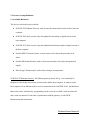
NI WSN 9792 Ethernet Gateway. The Ethernet gateway shown in Fig. 1 can essentially be
thought of as the bridge between the wireless nodes and the host computer. It connects to the
host computer via an Ethernet cable to receive instructions from LabVIEW 2010+ and broadcast
them to the nodes. Alternatively, programming can be received over both a local area network
and a wide area network. Each node is synchronized with the gateway via LabVIEW
Measurement and Automation..
Wireless Sensor Network 3
Fig. 1. NI WSN 9792 Ethernet Gateway
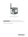
NI WSN 3202 Wireless Node. The NI WSN 3202 Wireless Node shown in Fig. 2 is a
programmable wireless receiver that transmits data from a sensor to the gateway. This particular
node contains 4 analog and 4 digital inputs.
Wireless Sensor Network 4
Fig. 2. NI WSN 3202 Wireless Node
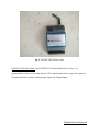
NI WSN 3212 Wireless Node. The NI WSN 3212 Wireless Node shown in Fig. 3 is a
programmable wireless receiver that, like the 3202, transmits data from a sensor to the gateway.
This particular node contains 4 thermocouple inputs and 4 digital inputs.
Wireless Sensor Network 5
Fig. 3. NI WSN 3212 Wireless Node
National Instruments Remotely Programmable Ethernet Gateway. This gateway, which replaces
the NI WSN 9791 Gateway in this project, allows for the programming of the wireless nodes
from remote locations on a network.
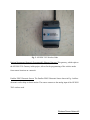
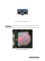
Parallax PING Ultrasonic Sensor. The Parallax PING Ultrasonic Sensor shown in Fig. 4 utilizes
ultrasonic audio chirps to detect motion. The sensor connects to the analog input of the NI WSN
3202 wireless node.
Wireless Sensor Network 6
Fig. 4. Parallax PING UltraSonic Sensor
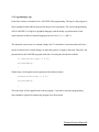
Infrared Sensor. The infrared sensor shown in Fig. 5, provides data about the temperature of an
object. Like the PING sensor, it connects to an analog port on the NI WSN 3202 wireless node.
Fig. 5. Parallax PIR Infrared Sensor
Wireless Sensor Network 7
2.2. Programming Logic
Each of the sensors is monitored via a LabVIEW 2010 programming. The logic to the program is
fairly straight-forward and has been used in the previous experiment. The selected programming
API is LabVIEW G, a high level graphical language with the ability to perform many of the
same functions as Object Oriented Languages such as: Java, C, C++, and C#.
The ultrasonic sensor runs at a constant voltage of 0.5V when there is no motion detected. Once
motion is detected, the voltage changes in either the positive or negative direction. Therefore, the
pseudocode for the LabVIEW program at the time of writing this document would be:
if (detectedVoltage != 0.5){
activateLED();
}
Similar logic can be applied to the operation of the infrared sensor:
if(detectedVoltage != 0.5){
activateLED();
}
This same logic will be applied to the remote program. Very little to no actual programming
logic should be required to transmit the program over the network.
Wireless Sensor Network 8
To create the program in LabVIEW, the sensor nodes must be connected to the Ethernet gateway
in software via NI Measurement and Automation Explorer. To do so, follow the following steps:
● Open NI Measurement and Automation Explorer.
● Expand the Remote Systems Tree.
● The NI WSN 9791 Ethernet Gateway should automatically be detected. Click it.
● On the screen that appears after clicking the gateway, click the nodes tab.
● Click add nodes.
● Enter the type of node and the serial number of the node.
● Repeat for each additional node.
Once the nodes are added to the gateway, the user can now create an empty LabVIEW project.
Once the project is created in LabVIEW:
Right click the project name.
Select New >> Targets and Devices...
Select Existing Targets or Devices
Expand the WSN Gateway folder to choose the 9791 Ethernet Gateway configured in
Measurement and Automation.
The measurement nodes configured with the network are automatically added underneath
the gateway in the LabVIEW Project, giving an instant access to their I/O variables and
properties.
Drag the AI0 from the 3202’s I/O tree on the left hand side of the screen onto the block
diagram and attach it to an indicator. Do the same for the TC0. More detailed information
can be found in the User Manual section of this document. (see Appendix)
Wireless Sensor Network 9
3. New Objectives
In the previous project, a running example consists of the graphs displaying the correct voltage
of both the ultrasonic sensor and the infrared sensor. In addition to this, when the desired result is
obtained (motion detected/temperature achieved), the program turns on the LED in LabVIEW,
This experiment will be kept in the current project.
A new objective in this iteration of the project is that the security system’s program will be sent
to the wireless nodes and run on LabVIEW from a remote location on the network (Fig. 6). From
there, it is only a matter of forwarding the correct ports in order to access the gateway over the
Internet. A successful trial will be defined as one in which the wireless nodes correctly display
the alarm status.
Wireless Sensor Network 10
Fig. 6: Diagram depicting the way in which the hardware interacts.
Wireless Sensor Network 11
4. Conclusion
The current status of the project is that the gateway is able to be programmed remotely from any
computer on the FGCU public, wired network. The gateway can also be programmed over the
Internet, provided that the network hosting the gateway has the ports 3580, 3581, and 8080 open.
Since this project dealt solely with analog sensors, future projects should expand the LabVIEW
program to read and process data from digital sensors.
Wireless Sensor Network 12
5. References
[1] Parallax PING Ultrasonic Sensor Documentation, URL:
http://www.parallax.com/Portals/0/Downloads/docs/prod/acc/28015-PING-v1.6.pdf
[2] Parallax PIR Sensor Documentation, URL:
http://www.parallax.com/dl/docs/prod/audiovis/pirsensor-v1.2.pdf
[3] Getting Started with NI Wireless Sensor Networks, URL:
http://zone.ni.com/devzone/cda/tut/p/id/8890
[4] Data Acquisition with NI WSN Gateway and Nodes, URL:
http://itech.fgcu.edu/faculty/zalewski/projects/files/Wireless_Sensor_Network.pdf
Wireless Sensor Network 13
Appendix
User Manual
The purpose of this document is to guide the user step by step through the process of: (1)
controlling the sensor nodes remotely with Labview, and (2) updating sensor node software
through the gateway. Both can be done in two ways:
1. On the FGCU network using 172.28.xx.yy addresses.
2. From any network using ports 3580 and 3581, once they are open (assuming port 8080 is
already open).
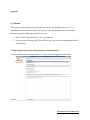
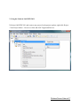
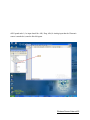
1. Importing the Gateway into Measurement and Automation 5.1
1.1. Open Measurement and Automation 5.1. In the screen that appears, click Remote
Systems
Wireless Sensor Network 14
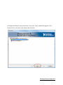
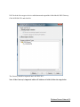
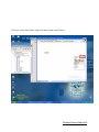
1.2. Right click Remote Systems and click Create New. In the window that appears, click
Remote Device (not on the local subnet) and click Next.
Wireless Sensor Network 15
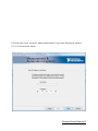
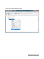
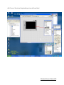
1.3. In the next screen, tick the IP Address Radio Button. Type in the following IP Address:
172.28.79.189 and click Finish.
Wireless Sensor Network 16
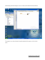
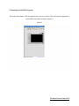
2. Using the Nodes in LabVIEW 2011
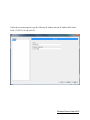
2.1. Open LabVIEW 2011 and create a new project. In the project explorer, right click Project:
<Your Project Name>. Hover over New and click Targets and Devices.
Wireless Sensor Network 17
2.2. Check the New target or device radio button and expand the folder labeled WSN Gateway.
Click NI WSN-9791 and click Ok
The Gateway should be imported into LabVIEW 2011.
Note: If the Gateway is imported with an IP Address of 0.0.0.0, follow the steps below.
Wireless Sensor Network 18
2.3. Right click the gateway and click Properties.
Wireless Sensor Network 19
2.4. In the screen that appears, type the following IP Address into the IP Address/DNS Name
Field: 172.28.79.189 and click Ok.
Wireless Sensor Network 20
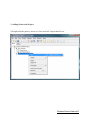
3. Adding Nodes to the Project
3.1. Right click the gateway, hover over New and click Targets and Devices
Wireless Sensor Network 21
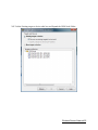
3.2. Tick the Existing target or device radio box and Expand the WSN Node Folder.
Wireless Sensor Network 22
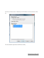
3.3. Click on a Node to select it. Alternatively Ctrl-Click Nodes to select more than one. Click
Ok.
The nodes should be imported into LabVIEW successfully.
Wireless Sensor Network 23
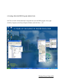
4. Creating a Basic LabVIEW Program with the Nodes
4.1. The two nodes will automatically be imported into your LabVIEW program. Next, right
click My Computer (in the Project Explorer Window) and click New >> VI.
Wireless Sensor Network 24
4.2. Expand node 1 (1st input should be: AI0). Drag AI0 (Or Analog input that the Ultrasonic
sensor is attached to) onto the block diagram.
Wireless Sensor Network 25
4.3. Next, on the Front Panel, right click and click the search button.
Wireless Sensor Network 26
4.4. Type in indicator. Double click the folder labeled Graph Indicators. A new group of items
will be added to the Express Menu.
Wireless Sensor Network 27
4.5. Choose a Waveform Graph and drag it into the Front Panel.
Wireless Sensor Network 28
4.6. Returning to the block diagram, create a wire between AI0 and the Waveform Indicator.
The program is now ready to display the signals transmitted to the gateway via the wireless
nodes.
Wireless Sensor Network 29
5. Running the LabVIEW Program:
5.1. In the Front Panel, click the symbol of two arrows in a loop. This will cause the program to
run until the stop button (orange octagon) is
pressed.
Wireless Sensor Network 30
6. Troubleshooting:
If the program does not work, make sure of the following:
● All wires are correctly connected. (Both securely and in the right ports)
● All LabVIEW wires are properly connected (No red X’s)
● The ethernet gateway is connected and detected in both LabVIEW and Measurement and
Automation.
● The wireless nodes have fresh, charged batteries.
For more help, visit: http://www.ni.com/support/
Wireless Sensor Network 31