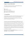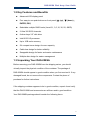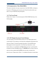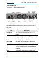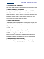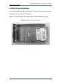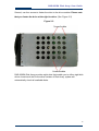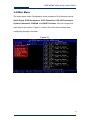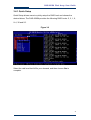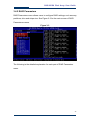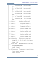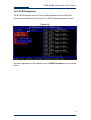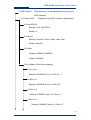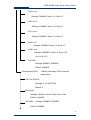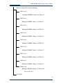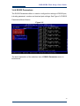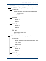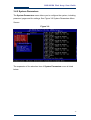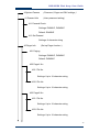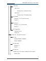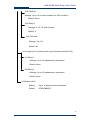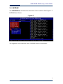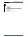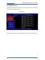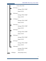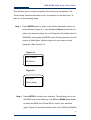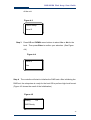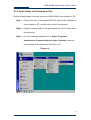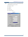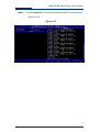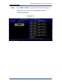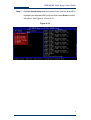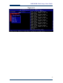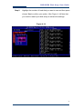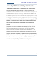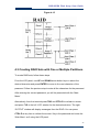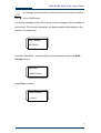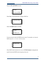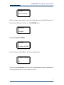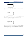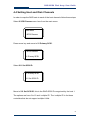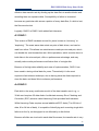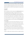
1
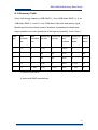
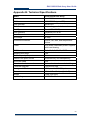
DAS-208SA Disk Array User Guide DAS-208SA Disk Array User Guide For Serial-ATA to Ultra320 RAID Subsystem v. 1.01b DAS-208SA Disk Array User Guide The information in this guide may be changed without notice. We assume no responsibility for any errors which may appear in this guide. Microsoft, Windows and Windows logo are trademarks of Microsoft Corporation. Copyright 2004. All rights reserved. No Part of the contents in this guide may be transmitted or reproduced in any form or by any means without the written permission of the manufacturer. Printed in Taiwan. The revision date for this guide is Apr. 30, 2004 Version 1.0 FCC Statement This equipment has been tested and found to comply with the limits for a Class A digital device, pursuant to Part 15 of the FCC Rules. These limits are designed to provide reasonable protection against harmful interference in a residential installation. This equipment generates and can radiate radio frequency energy and, if not installed and used according to the instructions, may cause harmful interference to radio communications. However, there is no guarantee that interference will not occur in a particular installation. If this equipment does cause harmful interference to radio or television reception, which is found by turning the equipment off and on, the user is encouraged to try to correct the interference by one or more of the following measures: --Reorient or relocate the receiving antenna --Increase the separation between the equipment and device --Connect the equipment to an outlet other than the receiver --Consult a dealer or an experienced radio/TV technician for assistance CE Mark Warning This is a Class A product. In a domestic environment, this product may cause radio interference in which case the user may be required to take adequate measures. 2 DAS-208SA Disk Array User Guide Chapter 1 General Information This chapter provides general information of the DAS-208SA Disk Array. The following topics are covered in this chapter: ◆ Introduction ◆ Key Features & Benefits ◆ Unpacking Your DAS-208SA Disk Array ◆ Components of DAS-208SA Disk Array 1.1 Introduction The DAS-208SA is a Serial ATA to Ultra320 SCSI RAID (Redundant Array of Independent Disks) Disk Array. By implementing sophisticated RAID technology and unique cache algorithm, this disk array provides the best protection for the data stored on the array. And thanks to today’s powerful disk technology, one RAID system can now provide the capacity more than 1TB in a large cabinet. This offers a wealth of significant advantages that would be attractive to almost any serious PC users. Equipped with eight half-height 3.5” disk drives in hot-swappable canisters, the DAS-208SA Disk Array provides mass data capacity and easy installation for the individual customers. In addition, this RAID system has dual host channels and high availability software that ensures 24 hours a day, seven days a week of nonstop service capability. Throughout this manual, the DAS-208SA Disk Array may be referred to as DAS-208SA, or simply as Disk Array. 3 DAS-208SA Disk Array User Guide 1.2 Key Features and Benefits Advanced LCD display panel Four easy-to-use push buttons on front panel (▲ (up), ▼ (down) ,, ENTER, ESC) Selectable multiple RAID levels (Level 0,1, 3,5,10, 30, 50, JBOD) 2 Ultra 320 SCSI channels 8 driver bays 3.5” disk drive Intel 80321 IO processor Up to 1GB cache memory 2U compact tower design for more capacity Cable-less design for better reliability Swappable design for faster and easier maintenance Multiple alter design for easier management 1.3 Unpacking Your DAS-208SA Before removing your DAS-208SA from the shipping carton, you should virtually inspect the physical condition of the container. The package of DAS-208SA should appear in good condition when you first received it. If any damaged found, do not remove the components. Contact the place of purchase for further instructions. If the shipping container appears to be in good condition, unpack it and verify that the DAS-208SA and accessories are all there and in good condition. Your DAS-208SA package should contain the following items: 4 DAS-208SA Disk Array User Guide Items Quantity DAS-208SA unit 1 Drive Canister 8 Ultra320 SCSI Cable 1 Power Cord 2 RS-232 Cable 1 User Manual CD 1 Spare screws 40 If any item is missing or damaged, please contact the place of purchase for assistance. Retain the shipping container and packing material for reuse. Before you begin to use your DAS-208SA, read section 1.4 Note Components of the DAS-208SA to learn more about the major components or your RAID Disk Array. 5 DAS-208SA Disk Array User Guide 1.4 Components of the DAS-208SA This section describes the major components of the DAS-208SA, including its front panel, LED display panel and rear panel. Read this section before you start to use your RAID Disk Array Subsystem. 1.4.1 The Front Panel Please refer to Figure 1-1 for the front panel of DAS-208SA Disk Array in the following page. 1.4.2 LCD Display Panel and Control Buttons The control panel of the DAS-208SA consists of a LCD display panel and 4 control buttons. This is where you will check the configuration and status of the disk array. Figure1-2 shows the general information, such as RAID status, thermograph, and fan temperature of the Disk Array. Meanwhile, control buttons allow you to use Up (▲) and Down (▼) arrow keys to go through the information on the LCM display screen. The ENTER button is used to enter the option you have selected and the ESC button can take you back to the previous menu. Please refer to Table 1-1 for detailed information of each status. 6 DAS-208SA Disk Array User Guide For the status of each hard disk in Disk Array, please refer to Table 1-2. Meanwhile, for fans and power error messages, alarm and indicators shown on the LCD, please refer Table 1-3. Table 1-1 Items Status Description DAS-208SA Disk Array Indicates the model name of the product Installed Memory 128 Mbytes Indicates the capacity of the memory CPU Type: 80321 4 Ultra320 Indicates the CPU model and interface Firmware Version v. 1.0 Indicates the version of the firmware Serial Number: xxxxxxxxxxxxx Indicates the serial number of the RAID controller FAN1 RPM* FAN2 RPM* Indicates the speed of Fan 1 Indicates the speed of Fan 2 Temp 1 Indicates the temperature of the upper part of the backplane. Temp 2 Indicates the temperature of the central part of the backplane. Temp 3 Indicates the temperature of the bottom part of the backplane. ZzZZZzzz Indicates the random display when parity checking z A single “z” appearing at the right end of the LCD panel (eg. 11112222z ) indicates that memory is not enough during read & write. * Please note that RPM under 2200 will be considered fan failure; replace the fan immediately for better performance. 7 DAS-208SA Disk Array User Guide Table 1-2 Hard Disk Status Letter shown on LCD JBOD J Disk Offline X Disk Rebuilding A Disk Removed R Spare Disk S Disk Initializing I RAID Set 1 1 RAID Set 2 2 RAID Set 3 3 RAID Set 4 4 Too many bad sector W Table 1-3 Item LCD show Fan module#1 fail LCD show Fan module#2 fail LCD show power module#1 fail LCD show power module#2 fail Error messages shown on LCD “Fan1 Failed” “Fan2 Failed” “PW1 Malfunction” “PW2 Malfunction” Table 1-4 Function Condition Temperature Sensor at 30℃ Temperature Sensor at 31- 35℃ Temperature Sensor at 36- 40℃ Temperature Sensor over 40℃ FAN 1 failed FAN 2 failed Any power module failed FAN status FAN 1 FAN 2 ≒5000 rpm ≒5600 rpm ≒6200 rpm ≒5000 rpm ≒5600 rpm ≒6200 rpm Full Speed(6800) x Full Speed(6800) Full Speed(6800) Full Speed(6800) Full Speed(6800) x Full Speed(6800) 8 DAS-208SA Disk Array User Guide 1.4.3 The Rear Panel The rear panel of DAS-208SA is shown below. Refer to Table 1-4 for detailed description of each part on the rear panel of DAS-208SA. Table 1-4 Part Modem port Description This is where you can connect your disk array to a modem. Console port This is a RS-232 serial port, allowing you to connect to a terminal or a PC. You may configure this disk array, and upgrade the firmware and RAID. Primary and DAS-208SA has two host channels—primary and Secondary Channels secondary—to allow you to connect to SCSI devices. Fan There are 2 fans located at the rear of the system unit. They are designed to provide good airflow and heat dissipation. Power The disk array comes with 2 hot-swappable power 9 DAS-208SA Disk Array User Guide supplies located at the rear of the subsystem. If two of the power supplies are in use and one fails to function, an audible alarm will warn you of the power failure. Power Cord Slot These are where you connect power cords to power socket. 10 DAS-208SA Disk Array User Guide Chapter 2 Hardware Installation This chapter discusses the basic operational installation and the Disk Drive installation. The following topics are covered in this chapter: Preparing for the Installation Disk Drive Installation Table and Shelf Installation Rack-Mount Installation Tower Conversion kit Installation 2.1 Preparing for the Installation If you will be connecting your DAS-208SA Disk Array to the computer using a SCSI adapter, installed the adapter(s) in an available slot in the computer prior to beginning the DAS-208SA installation. See your operating system manuals for the configuration procedures for the host bus adapter. 2.1.2 Terminating Disk Drive Channels All SCSI buses must be terminated at each end. Termination absorbs electrical signals and prevents those signals from bouncing back along the bus and causing interference. The SCSI drive channels of the DAS-208SA have been terminated inside the chassis on the back plane. There is no need to terminate the disk drives! 11 DAS-208SA Disk Array User Guide 2.1.3 Connecting the DAS-208SA DAS-208SA can be connected to the host computer via 2 Ultra320 SCSI ports. 2.1.4 Host Bus SCSI ID Assignment You may assign any SCSI ID to the host channel. The range of SCSI IDs on a Wide SCSI bus starts from 0 to 15. You can use the LCD panel or a terminal to set the host channel ID. (Refer to Section 3.1 Configuration Methods for more information.) Be sure to assign an ID that does not conflict with any other devices on the host bus as well as the host adapter. 2.1.5 Host Bus Termination The disk array is shipped with host channel buses terminated. If the disk array is not the last device on the host bus, you must turn off termination from the LCD panel or a terminal. 2.1.6 Back Plane The back plane of the DAS-208SA is specifically designed to furnish the stability of voltage and provide the reliability for disk array. 2.1.7 Connecting the Power Cord Before you connect the power cords to the power supplies, make sure the power supplies have been firmly seated inside the DAS-208SA Disk Array. 2.1.8 Uninterruptible Power Supplies To insure the integrity of the data stored on a RAID array, we strongly recommend connecting the DAS-208SA Disk Array to an external UPS. 12 DAS-208SA Disk Array User Guide 2.2 Disk Drive Installation Any 3.5“ Serial-ATA hard disk, half-height 1” (2.54cm) SCA connector can be installed into the canister of DAS-208SA. Figure 2-1 shows the disk drive and canister of DAS-208SA Disk Array. Figure 2-1 Disk Drive and Canister 13 DAS-208SA Disk Array User Guide Second, use four screws to fasten the drive to the drive canister. Please note that you fasten the drive at the right location. (See Figure 2-2) Figure 2-2 DAS-208SA Disk Array provides eight slots that enable you to utilize eight disk drives. Insert each slot to the drive canister of Disk Array; system will automatically check all available disks. 14 DAS-208SA Disk Array User Guide Chapter 3 Configuration FASTORA DAS-208SA can be configured via its LCD panel or via a terminal. This chapter will discuss the configuration methods and the detailed information about the operation modes. This chapter covers the following topics: Configuring Through the LCD Display Panel Configuring Through a Terminal Operation Modes Main Menu 3.1 Configuring Through the LCD Display Panel The LCD Panel consists of a two lines 16-character LCD display, two LED indicators, four push buttons, and a reset button, allowing users to configure and monitor the operation of the disk array. A menu of configuration options will appear on the display. By using the (▲) Up arrow, (▼) Down arrow, ESC, and ENTER buttons, users can traverse various menu levels and configure his desired parameters. The function of the buttons is descried as follows: (▲) Up Arrow To scroll upward through the menu items; (▼) Down Arrow To scroll downward through the menu items; Enter To select a menu item, open a sub-menu, and select a value ESC To exit a sub-menu and returns to the previous menu. 15 DAS-208SA Disk Array User Guide If you wish to start with the LCD display panel as quickly as Note possible, refer to Chapter 4.1.1Quick Setup via LCD Display Panel to configure the disk array. 3.2 Configuring Through a Terminal The LCD control panel allows the exploration of all configurable features of the disk array. However, the frame of the LCD panel only allows a few messages of output. In this case, a very limited amount of information can be displayed at a given time on the LCD display panel. In fact, using a terminal to configure your disk array will be exactly the same as using the LCD display to do the configuration. Unlike the LCD display that can only show 2 lines of the configuration information, a terminal, connected via a modem or direct serial interface, displays all information pertinent to a particular function on a larger terminal screen. In addition, the help information, which is impractical to be shown on the LCD panel, is also available on the terminal. 3.2.1 Connecting a Terminal Located at the rear of the disk array, a RS-232 connector, marked as Console, can be used to support the local terminal access. When connecting a terminal to the disk array, make sure you have attached the supplied RS-232cable to the right Console connector. Note that you should set up the communication parameters before using this terminal. To start up: 1. Plug one end of the supplied RS-232 cable to the port marked as Console at the rear of the disk array. 2. Connect one end of the RS-232 cable to the COM port of your terminal or PC. 3. Run an equivalent program of the terminal. 4. Change the setting of the terminal to match the default settings of the 16 DAS-208SA Disk Array User Guide FASTORADAS-208SA, namely: Baud rate: 115,200 Data bit: 8 Stop bit: 1 Parity: None Flow Control: None You shall see a pop-up screen indicating that the connection has been setup successfully. Then, you may configure the disk array with your terminal. Refer to section 3.2.3 Control Key Definition under ANSI Terminal to learn the control keys for terminal emulation. Please note that if you wish to start to configure with your terminal as quickly as possible, you may refer to Section 4.1.2 Quick setup via Terminal Configuration. 3.2.2 Using PC for Terminal Emulation If you do not have a dedicated terminal, you can still use a PC configured as a terminal, running a terminal emulation program. Microsoft Windows and Windows 95 both have built-in terminal emulation support. Please select ANSI terminal as the terminal type for the terminal emulation. You can also use other terminal emulation programs such as KERMIT or VTERM. If you cannot see anything on the screen after the session has been established, press TAB key followed by Ctrl-D key combination to refresh the screen. Follow the same steps discussed in section 3.2.1 Connecting a Terminal to connect your PC to the disk array. 17 DAS-208SA Disk Array User Guide 3.2.3 Control Key Definition under ANSI Terminal Using ANSI terminal display, the following keys are supported: A - used to scroll upward through the menu items Z - used to scroll downward through the menu items ENTER - used to select a menu item, open a sub-menu, and select a value ESC - used to exit a sub-menu and return to the previous menu TAB - used to switch between windows The rest of the alphanumeric keys are also supported for password input and when prompted for Yes or No input. 3.3 Operation Modes DAS-208SA Disk Array has three operation modes: Self-Diagnostic Mode, Operation Mode, and Configuration Mode. We will discuss each of the RAID disk array operation mode in the following sections. 3.3.1 Self Diagnostic Mode To ensure flawless operation, the disk array has a built-in self-diagnostic utility. Self-diagnostics will be performed automatically upon power up of the disk array or right after you restart the unit. In this mode of operation, all components will be tested. If any problem occurred, it will report to the user. The Self-Diagnostic mode runs three major diagnostics. The first diagnostic tests the CPU and supporting the core logic chips, internal bus, memory, SCSI controllers, and RS-232 controllers. The second diagnostic tests the presence of disks on each individual disk channel. It also checks the functionality of the disks found. The last diagnostic tests RAID functionality. 18 DAS-208SA Disk Array User Guide 3.3.2 Operation Mode Operation mode continuously reports the operating status of the disk array and the drives connected to it. During normal operation, the LCD display will continuously show the status of all the major components. Note that the last character on the second line of the LCD panel with a tiny square moving up and down, to indicate that the DAS-208SA Disk Array is in operation. 3.3.3 Configuration Mode Configuration mode is used to modify the settings of disk array. Users can configure theDAS-208SA either through the LCD panel or via a terminal. Note that you are entering the configuration mode whenever you are pressing the SEL button during the Operation Mode. If you wish to enter to the configuration mode from a terminal, simply use the “TAB” key to take you to your desired mode. 1. You cannot enter the configuration Mode from LCD panel and Terminal at the same time. 2. You will be prompted to enter your password if the password-checking feature is enabled. Provide the correct password to continue your configuration. Unless the disk array is running the self-diagnose mode, you may select any of the configuration modes at any time. The configuration mode of DAS-208SA is completely menu-driven for the ease of use. And the menu options allow you to fine-tune disk array to your specific configuration. 19 DAS-208SA Disk Array User Guide 3.4 Main Menu The main menu under Configuration mode consists of the following menus: Quick Setup, RAID Parameters, SCSI Parameters, RS-232 Parameters, System Parameters, NVRAM, and RAID Functions. We will navigate the main tree in this section. Figure 3-1 shows the main menu screen when configuring through a terminal. Figure 3-1 20 DAS-208SA Disk Array User Guide 3.4.1 Quick Setup Quick Setup allows users to quickly setup the RAID level and choose the desired drives. The DAS-208SA provides the following RAID levels: 5, 3, 1, 0, 0+1, 30 and 50. Figure 3-2 Select the raid level that fulfills your demand, and then choose Yes to complete. 21 DAS-208SA Disk Array User Guide 3.4.2 RAID Parameters RAID Parameters menu allows users to configure RAID settings, such as array, partitions, slice and stripe size. See Figure 3-3 for the main screen of RAID Parameters menus. Figure 3-3 The following is the detailed explanation for each part of RAID Parameters menu. 22 DAS-208SA Disk Array User Guide 1 RAID Params (Creates RAID sets and partitions) 11 Array 1 (Configure the RAID set 1) 111 Re-Config RAID Setting: Default: (Configure the RAID set again) NO, YES NO 112 RAID Level (Select the RAID set's level) Setting: 0, 1, 3, 5, 0+1, 30, 50, None Default: None 113 Disk Number (Select the number of disks to construct the RAID set) Setting: 8, 7, 6, 5, 4, 3. (based on the RAID level) 114 Slice (Setup each slice's size) 1141 Slice 00 (MB) Key in size in MB 1142 Slice 01 (MB) Key in size in MB 1143 Slice 02 (MB) Key in size in MB 1144 Slice 03 (MB) Key in size in MB 1145 Slice 04 (MB) Key in size in MB 1146 Slice 05 (MB) Key in size in MB 1147 Slice 06 (MB) Key in size in MB 1148 Slice 07 (MB) Key in size in MB 1149 Slice 08 (MB) Key in size in MB 114A Slice 09 (MB) Key in size in MB 23 DAS-208SA Disk Array User Guide 114B Slice 10 (MB) Key in size in MB 114C Slice 11 (MB) Key in size in MB 114D Slice 12 (MB) Key in size in MB 114E Slice 13 (MB) Key in size in MB 114F Slice 14 (MB) Key in size in MB 114G Slice 15 (MB) Key in size in MB 12 Array 2 (Configure the RAID set 2) 13 Array 3 (Configure the RAID set 3) 14 Array 4 (Configure the RAID set 4) 15 Array 5 (Configure the RAID set 4) 16 Array 6 (Configure the RAID set 4) 17 Array 7 (Configure the RAID set 4) 18 Array 8 (Configure the RAID set 4) 19 Stripe Size (Setup the array's stripe size) Setting: 1024, 512, 256, 128, 64, 32, 16, or 8 sector Default: 128 1A Write Buffer (Enable/disable Write Buffer used) Setting: ENABLE, DISABLE Default: ENABLE 1B Performance (This allows you to select I/O policy) Setting: Random, Sequential Default: Sequential 24 DAS-208SA Disk Array User Guide 3.4.3 SCSI Parameters The SCSI Parameters menu is used to edit parameters of two SCSI host channels of the Disk Array. See Figure 3-4 SCSI Parameters Menu Screen. Figure 3-4 The brief explanation of the selection item of RAID Parameters menu is listed below: 25 DAS-208SA Disk Array User Guide 2 SCSI Params (This allows you to edit parameters of the primary SCSI channel) 21 Primary SCSI (Editing primary SCSI channel's parameters) 211 Set SCSI ID Settings: 0-14, MULTIPLE Default: 0 212 Speed Settings: Ultra320, Ultra3, Ultra2, Ultra, Fast Default: Ultra320 213 Wide Settings: ENABLE, DISABLE Default: ENABLE 214 LunMap (LUN to slice mapping) 2141 Lun0 Settings: DISABLE, Array 1-8, Slice 0 -- 7 2142 Lun 1 Settings: DISABLE, Array 1-8, Slice 0-7 2143 Lun 2 Settings: DISABLE, Array 1-8, Slice 0 - 7 2144 Lun 3 Settings: DISABLE, Array 1-8, Slice 0-7 26 DAS-208SA Disk Array User Guide 2145 Lun 4 Settings: DISABLE, Array 1-8, Slice 0-7 2146 Lun 5 Settings: DISABLE, Array 1-8, Slice 0-7 2147 Lun 6 Settings: DISABLE, Array 1-8, Slice 0-7 2148 Lun 7 Settings: DISABLE, Array 1-8, Slice 0-7 2149 Lun # Settings: DISABLE, Array 1-8, Slice 0-15 (for Lun 8-127) 214 QAS Settings: ENABLE, DISABLE Default: ENABLE 22 Secondary SCSI (Editing secondary SCSI channel's parameters) 221 Set SCSI ID Settings: 0-14, MULTIPLE Default: 0 222 Speed Settings: Ultra320, Ultra3, Ultra2, Ultra, Fast Default: Ultra320 223 Wide Settings: ENABLE, DISABLE Default: ENABLE 27 DAS-208SA Disk Array User Guide 224 Lun Map (LUN to slice mapping) 2241 Lun 0 Settings: DISABLE, Array 1-8, Slice 0-7 2242 Lun 1 Settings: DISABLE, Array 1-8, Slice 0-7 2243 Lun 2 Settings: DISABLE, Array 1-8, Slice 0-7 2244 Lun 3 Settings: DISABLE, Array 1-8, Slice 0-7 2245 Lun 4 Settings: DISABLE, Array 1-8, Slice 0-7 2246 Lun 5 Settings: DISABLE, Array 1-8, Slice 0-7 2247 Lun 6 Settings: DISABLE, Array 1-8, Slice 0-7 2248 Lun 7 Settings: DISABLE, Array 1-8, Slice 0-7 2249 Lun # Settings: DISABLE, Array 1-8, Slice 0-15 (for Lun 8-127) 225 QAS 28 DAS-208SA Disk Array User Guide Settings: ENABLE, DISABLE Default: ENABLE 29 DAS-208SA Disk Array User Guide 3.4.4 RS232 Parameters The RS232 Parameters Menu is used to configure the settings of RS232 port, including password, modem and terminal port settings. See Figure 3-5 RS232 Parameters Menu Screen. Figure 3-5 The brief explanation of the selection item of RS232 Parameters menu is listed below: 30 DAS-208SA Disk Array User Guide 3 RS232 Params (Password, Modem and Terminal port settings.) 31 MODEM Port (Set up MODEM port parameters) 311 Baud Rate Settings: 2400, 4800, 9600, 14400, 19200, 28800, 38400, 57600, 115200 Default: 115200 312 Stop Bit Settings: 1, 2 Default: 1 313 Data Bit Settings: 7, 8 Default: 8 314 Parity Settings: NONE, ODD, EVEN Default: NONE 32 Terminal Port (Set up Terminal port parameters) 321 Baud Rate Settings: 2400, 4800,9600, 14400,19200, 28800, 38400, 57600, 115200 Default: 115200 322 Stop Bit Settings: 1,2 Default: 1 323 Data Bit Settings: 7, 8 31 DAS-208SA Disk Array User Guide Default: 8 324 Parity Settings: NONE, ODD, EVEN Default: NONE 32 DAS-208SA Disk Array User Guide 3.4.5 System Parameters The System Parameters menu allows you to configure the system, including password, pager and fax settings. See Figure 3-6 System Parameters Menu Screen. Figure 3-6 The expansion of the selection item of System Parameters menu is listed below: 33 DAS-208SA Disk Array User Guide 4 System Params (Password, Pager and FAX settings.) 41 Passwd Info (User password setting) 411 Passwd Check Settings: ENABLE, DISABLE Default: ENABLE 412 Set Passwd Settings: 8-character string 42 Pager Info (Set up Pager function.) 421 Paging Settings: ENABLE, DISABLE Default: DISABLE 422 Pager1 No. 4221 Tel No. Settings: Up to 16-character string 4222 Pin No. Settings: Up to 16-character string 423 Pager2 No. 4231 Tel No. Settings: Up to 16-character string 4232 Pin No. Settings: Up to 16-character string 34 DAS-208SA Disk Array User Guide 424 Code 4241 Part 1 Settings: Up to 16-character string 4242 Part 2 Settings: Up to 16-character string 425 Repeat Settings: 5, 10, 15, and 20 minutes Default: 5 426 Interval Settings: 5, 10, 15, 20 minutes Default: 5 427 Paging Now Settings: Yes, No Default: No 43 FAX Info Set up FAX function.) 431 FAX Settings: ENABLE, DISABLE Default: DISABLE 432 FAX Class Settings: 1,2 Default: 1 433 FAX1 No. Settings: Up to 16 numeric numbers for FAX number 1 Default: None 35 DAS-208SA Disk Array User Guide 434 FAX2 No. Settings: Up to 16 numeric numbers for FAX number 2 Default: None 435 Retry # Settings: 5, 10, 15, and 20 times Default: 5 436 FAX Now Settings: Yes, No Default: No 44 Company Info (Used to enter Log information with the FAX.) 441 String 1 Settings: Up to 16 alphanumeric characters Default: None 442 String 2 Settings: Up to 16 alphanumeric characters Default: None 45 Modem Init St Setting: Up to 16 alphanumeric characters Default: AT&DO&K4EO 36 DAS-208SA Disk Array User Guide 3.4.6 NVRAM The NVRAM Menu describes the information of the controller. See Figure 3-7 NVRAM Menu Screen. Figure 3-7 The expansion of the selection item of NVRAM menu is listed below: 37 DAS-208SA Disk Array User Guide 5 NVRAM (Saves the information related to the controller or reboots it.) 51 Update NVRAM (Update the RAID controller's configuration) Settings: NO, YES Default: NO 52 Erase NVRAM (Erase the RAID controller's configuration) Settings: NO, YES Default: NO 53 Restart (Reboot the RAID controller.) Settings: NO, YES Default: NO 38 DAS-208SA Disk Array User Guide 3.4.7 RAID Functions The RAID Functions menu allows you to check the system status. See Figure 3-8 RAID Functions Menu Screen. Figure 3-8 The expansion of the selection item of RAID Functions menu is listed below: 39 DAS-208SA Disk Array User Guide 6 RAID Funcs (Utility to check the disk array status.) 61 Init Parity (Force to initialize a level 5 , 3, 30, 50 disk array) 611 Array 1 Settings: STOP, START Default: STOP 612 Array 2 Settings: STOP, START Default: STOP 613 Array 3 Settings: STOP, START Default: STOP 614 Array 4 Settings: STOP, START Default: STOP 615 Array 5 Settings: STOP, START Default: STOP 616Array 6 Settings: STOP, START Default: STOP 617 Array 7 Settings: STOP, START Default: STOP 618 Array 8 Settings: STOP, START Default: STOP 62 Parity Check (Force to check a level 5 .3, 30, 50 disk 40 DAS-208SA Disk Array User Guide array's parity data) 621 Array 1 Settings: STOP, START Default: STOP 622 Array 2 Settings: STOP, START Default: STOP 623 Array 3 Settings: STOP, START Default: STOP 624 Array 4 Settings: STOP, START Default: STOP 625 Array 5 Settings: STOP, START Default: STOP 626 Array 6 Settings: STOP, START Default: STOP 627 Array 7 Settings: STOP, START Default: STOP 628 Array 8 Settings: STOP, START Default: STOP 63 Beeper (Setup beeper state.) 41 DAS-208SA Disk Array User Guide Settings: CLEAR, ENABLE, DISABLE Default: ENABLE 64 Stop Modem (Force to stop the modem operation) Settings: NO, YES Default: NO 65 Add Disk (Notify RAID controller to add a disk to system.) Settings: Disk 1 ~ 8 Default: NONE 66 Remove Disk (Notify RAID controller to remove a disk from system.) Settings: Disk 1 ~ 8 Default: NONE 67 Statistic (Display all statistic data on terminal.) Statistics: Company Info, FAX Info, Pager Info, I/O Statistic 68 Expand Array (this is used to expand the disk array.) 681 Array 1 Select number of disks 682 Array 2 Select number of disks 683 Array 3 Select number of disks 684 Array 4 Select number of disks 685 Array 5 Select number of disks 686 Array 6 Select number of disks 687 Array 7 Select number of disks 42 DAS-208SA Disk Array User Guide 688 Array 8 Select number of disks 69 Update ROM (Update the RAID controller’s firmware) 43 DAS-208SA Disk Array User Guide Chapter 4 Quick Setup Guide This Chapter describes the steps necessary to configure a disk array for the first time and create a disk array with different configurations. Before you configure the disk array, we recommend that you create a plan. For example, what RAID levels you will create and how many partitions you will need, etc. This chapter covers the following topics: Quick Setup Creating RAID Sets and Setup Host Channels Creating RAID Sets with One or Multiple Partitions Setting up Host and Disk Channels Spare Drives designation Setting Up Alert Functions Rebuilding a Failed Disk Drive Deleting a RAID Set or a Partition of RAID Set 4.1 Quick Setup The quick setup is intended as a shortcut so that experienced users can get started as quickly as possible. You will learn how to quickly set up yourDAS-208SA from the LCD panel or a terminal in this section. 4.1.1 Quick Setup via LCD Panel A default configuration, which is based on the number of the installed drivers, has been set within the unit for the ease of installation for the first time user. 44 DAS-208SA Disk Array User Guide This will allow you to verify the integrity of the disk array immediately. The “Quick Setup” assumes that there is only one partition on the disk array. To start up, do the following steps: Step 1 Press ENTER button to select to the “Enter Password” screen as shown below in Figure 4-1. Use the Up and Down arrow button to select your desired number for your Password (The default value is 00000000). Keep pushing ENTER button for the password. You will receive a “Main Menu” option screen once you enter a correct password. (See Figure 4-2) Figure 4-1 Enter Passwd: 0XXXXXXX Figure 4-2 Main Menu 0 Quick Setup Step 2 Press ENTER to confirm your selection. This will bring you to set the RAID level of the disk array. Use UP and DOWN arrow button to select the RAID level. Press SEL to confirm your selection again. Figure 4-3 shows the default value of the RAID set (RAID 5) 45 DAS-208SA Disk Array User Guide of the unit. Figure 4-3 0 Quick Setup Level 5 Step 3 Press UP and DOWN arrow buttons to select Yes or No for the level . Then press Enter to confirm your selection. (See Figure 4-4 ) Figure 4-4 Level 5 Yes Step 4 The controller will start to initialize the RAID sets. After initializing the RAID set, the subsystem is ready for the host OS to perform high-level format. (Figure 4-5 shows the result of the Initialization ) Figure 4-5 Initial(1) 5% RAID Ready 46 DAS-208SA Disk Array User Guide 4.1.2 Quick Setup via Terminals or PCs Do the following steps to quickly set up your DAS-208SA via a terminal or PC. Step 1 Connect one end of the supplied RS-232 cable to the COM port of your terminal or PC, and the other end to Console port. Step 2 Plug the multiport cable to the port marked as “AUX” at the rear of the disk array. Step 3 From the windows desktop click on Start> Programs> Accessories> Communications> Hyper Terminal to connect your terminal to the disk array. See Figure 4-8 Figure 4-8 47 DAS-208SA Disk Array User Guide Step 4 Change the setting of the terminal to match the default settings ofDAS-208SA (See Figure 4-9), namely: Baud rate: 115,200 Data bit: 8 Stop bit: 1 Parity : None Flow Control: None Figure 4-9 48 DAS-208SA Disk Array User Guide Step 5 Press Control-D to receive the following RAID Console screen. (Figure 4-10) Figure 4-10 49 DAS-208SA Disk Array User Guide Step 6 Press TAB and Enter key, a password screen will prompt up. (See Figure 4-11) Then, enter the password. (Default Password:00000000) Figure 4-11 50 DAS-208SA Disk Array User Guide Step 7 Highlight Quick Setup and then press Enter. Use key A and Z to highlight your desired RAID level and then press Enter to select the option. See Figure 4-12 and 4-13 Figure 4-12 51 DAS-208SA Disk Array User Guide Figure 4-13 52 DAS-208SA Disk Array User Guide Step 8 Highlight the number of hard disk you want to use and then press choose Yes to confirm your option. (See Figure 4-14) Note that you need to restart your disk array to activate the settings. Figure 4-14 53 DAS-208SA Disk Array User Guide Step 9 The controller will start to initialize the RAID sets. After initializing the RAID set, the subsystem is ready for the host OS to perform high-level format. 54 DAS-208SA Disk Array User Guide 4.2 Creating RAID Sets and Setup Host Channels The disk array has great flexibility in creating RAID sets. Drives of different sizes and manufacturers may be combined in a RAID set (Although the smallest drive in the set will limit how much of the other drives‘ capacity can be used). The disk array can have as many as 4 RAID sets. Each RAID set can be assigned a different RAID level. A RAID set may be partitioned into as many as 4 partitions. Each partition could be mapped to the LUNs of host channel 1 and/or 2. Each host channel will have 8 LUNs maximum for mapping the RAID partitions. In the following section we will outline the steps needed to create RAID sets with multiple partitions and then maps them to different host channels. For example, you want to create a disk array with two RAID sets. The first RAID set has two partitions using three drives with RAID level 5 and the second one has only one partition using two drives with RAID level 1. The partitions of the first RAID set are mapped to the LUN0 and LUN1 of the host channel 1 respectively. The partition of the second RAID set is mapped to the LUN2 of the host channel 1. In addition, the first partition of the first array and that of the second one set are mapped to the LUN0 and LUN1 of the host channel 2 respectively. The Figure 4-15 shows the configuration. 55 DAS-208SA Disk Array User Guide Figure 4-15 4.3 Creating RAID Sets with One or Multiple Partitions To create RAID sets, follow these steps. From the LCD panel, use UP and DOWN arrow button keys to select the desired character and press ENTER to move to the next character of the password. Follow the previous step to enter all the characters for the password. After entering the correct password, you will be presented with the ‘Main Menu’. Alternatively, from the terminal press TAB and CTRL-D to refresh to screen and press TAB to the left ‘LCD’ window for the desired selection. The right ‘OUTPUT’ window will display messages from the RAID. You can press CTRL-D at any time to refresh the screen. Key in the password and enter the ‘Main Menu’ as if using the LCD panel. 56 DAS-208SA Disk Array User Guide It is strongly recommended to use the terminal or terminal emulation Note for the RAID setup. The set up message on the LCD is shown in the rectangle in the remainder of this manual. The terminal (emulation) will display detailed information on the monitor in a similar way. Enter Passwd: 0XXXXXXX From the ‘Main Menu’, use A or Z key of the keyboard to move to 1 RAID Params function. Main Menu 1 RAID Params Press Enter to select. 1 RAID Params 11 Array 1 57 DAS-208SA Disk Array User Guide Select the Re-conf RAID and enter. 11 Array 1 111 Re-Conf RAID Select Yes and press ENTER to configure RAID Set 111 Re-Conf RAID Yes Select 112 RAID Level to set RAID. 11 Array 1 112 RAID Level Use arrow keys to select the RAID level you want. For example, you may set RAID level as 0, 1, 3, 5, 0+1, 30, 50, or none. 112 RAID Level 0 When RAID levels has been set, move to 113 Disk Number to designate the specific drives that RAID levels are going to be used. 58 DAS-208SA Disk Array User Guide 11 Array 1 113 Disk Number When it is done, remember to save all configurations so that RAID levels will be recorded and start to work. Go to 5 NVRAM menu. Main Menu 5 NVRAM Select 51 Update NVRAM. 5 NVRAM 51 Update NVRAM Use arrow keys, select Yes to save the configurations. 51 Update NVRAM Yes Then move to 53 Restart, and select Yes so that system will be restarted and all configurations will be done and start to work. 59 DAS-208SA Disk Array User Guide 53 Restart Yes Next, you may configure the partitions on the disk drives by moving to 114 Slice. 11 Array 1 114 Slice Select 1141 Slice 0 and enter the size of the partition 1 of the RAID set 1 in MB. For example, enter 4000 and press Enter. You may repeat the same procedure to configure Slice1 to Slice7. 1141 Slice0 (MB) 4000 When it is done, remember to save all configurations in 51 Update NVRAM, so that all settings will be saved. Then move to 53 Restart to reboot the system and new configurations will start to work. 60 DAS-208SA Disk Array User Guide 4.4 Setting Host and Disk Channels In order to map the RAID sets to each of the host channels follow these steps. Select 2 SCSI Params menu item from the main menu. Main Menu 2 SCSI Params Press arrow key and move to 21 Primary SCSI’. 2 SCSI Params 21 Primary SCSI Select 211 Set SCSI ID. 21 Primary SCSI 211 Set SCSI ID Move to 211 Set SCSI ID, this is the RAID SCSI ID recognized by the host 1. The options are from 0 to 15 and ‘multiple ID’. The ‘multiple ID’ is for those controllers that do not support multiple LUNs. 61 DAS-208SA Disk Array User Guide Move to 212 Tag Queue menu item. Queue the SCSI commands in the controller. Enabling tag queuing will improve the performance of the RAID. If your SCSI host adapter has an option of enabling the tag queuing, make sure to enable it. Press ENTER to Enable. 21 Primary SCSI 212 Tag Queuing The 213 Speed options are to be set according to the host 1 SCSI bus. Next, move to LUN 0 215 Lun Map 2151 Lun 0 Press Enter to select ‘LUN 0’, and move to ‘Array 1 ’. 2151 LUN 0 21511 Array 1 Select Slice 0, press Enter to complete. 21511 Array 1 Slice 0 62 DAS-208SA Disk Array User Guide Remember to save your configurations in 51 Update NVRAM. Press Enter and the RAID will begin to initialize the disks. Initial (1/2) 5% RAID Ready Where (1/2) is the first of the two RAID sets. INIT OK! RAID Ready Now the RAID is ready for the host OS high-level format. 63 DAS-208SA Disk Array User Guide 4.5 Spare Drives designation The disk array automatically identifies the drive in the enclosure that is not included by any RAID set as a spare drive. 4.6 Setting up Alert Functions There are two alert functions provided by the disk array. You could choose to send the warning messages to a fax or to a pager. The steps needed to setup the functions are shown below. Select the 4 System Params function from the main menu. Main Menu 4 System Params Select the 42 Page Info or 43 FAX Info you wish to complete. 4 System Params 42 Pager Info Or, 4 System Params 43 FAX Info 64 DAS-208SA Disk Array User Guide From the 42 Pager Info sub-menu, there are a few options to setup. 421 Paging: To enable or disable the paging function. 422 Pager 1 No.: Paging the first number. 423 Pager 2 No.: If the pager 1 number failed, page this number. 424 Code: Address the RAID ID for paging message. 425 Repeat #: Try to page number of times if it cannot get through. 426 Interval: The time between each page in minutes. 427 Paging Now: Test the set up of the paging function. From the ‘43 FAX Info’ sub-menu, there are a few options to setup. 431 FAX: To enable or disable the paging function. 432 FAX Class: Set up the Class of FAX. 433 FAX 1 No.: FAX to the first number. 434 FAX 2 No.: If the FAX 1 number failed, fax to this number. 435 Retry #: Try to FAX number of times if it cannot get through. 436 FAX Now: Test the set up of the FAX function. The contents of the FAX are entered in 44 Company Info. 441 String 1: Set up the RAID ID for FAX. 442 String 2: Set up the RAID ID for FAX In addition, the MODEM initialization string is entered in 45 Modem Init String. After the setup, remember to go back to the Main Menu and select 51 Update NVRAM to save all the settings just made. 65 DAS-208SA Disk Array User Guide 4.7 Rebuilding a Failed Disk Drive If you have a spare drive on the system, the controller will rebuild the disk array automatically. Select the 6 RAID Funcs from main menu. Main Menu 6 RAID Funcs Select the 65 Add Disk option, press Enter and specify which slot has a newly installed disk drive.DAS-208SA Disk Array has all the slots numbered on the front panel (HD1 – HD8). For example, the fourth slot has a new disk. 65 Add Disk Disk 4 System will automatically rebuild the new disk. Wait for a while for completion. 66 DAS-208SA Disk Array User Guide 4.8 Deleting a RAID Set or a Partition of RAID Set Warning! All the data will be lost in the deleted partition. Remember to backup your data before the deletion. Select the 2 SCSI Params function from main menu. Main Menu 2 SCSI Params Select the 21 Primary SCSI function. 2 SCSI Params 21 Primary SCSI Select 215 Lun Map, then select 2151 Lun 0 => 21511 Array 1. 21511 Array 1 Slice 0 Press Enter, then use arrow key to select Disable. All the data will be lost after you choose Disable. Backup all your data before proceeding! 67 DAS-208SA Disk Array User Guide 21511 Array 1 Disable Next, move to 1RAID Params from Main menu. Main Menu 1 RAID Params From the Main Menu, follow 11 Array 1 => 111 Re-conf RAID (Select Yes)=> 112 RAID Level 112 RAID NONE Go to 51 Update NVRAM to save all configurations. 68 DAS-208SA Disk Array User Guide Chapter 5 Upgrading Your Firmware In this chapter, we’ll discuss two different firmware upgrade procedures. The embedded firmware of the disk array can be updated through the TERMINAL port using a PC running terminal emulation program. However, you need another procedure to upgrade the firmware of 8051. Read this chapter carefully if you want to upgrade the latest firmware for yourDAS-208SA Disk Array. 5.1 Disk Array Firmware Upgrade The embedded firmware of the disk array can be updated through the TERMINAL port using a PC running terminal emulation program. The procedures are as below: Select the “9 Utilities” function from main menu. From the “9B Update ROM” option you could change the firmware of the disk array. After the “9B Update ROM” option is selected, follows the messages as below to update the firmware. Before downloading the new firmware, shutdown the host computer system. Are you ready to download the new firmware? Are you sure? Begin firmware file transfer now. To abort download, restart the RAID system. (After you key in the answer, select the ASCII file transfer to download (Y/N) the new firmware.) (Y/N) Y Y DAS-208SA Disk Array User Guide 00001A00 (the number will run indicating the file download) File transfer complete. Checksum = 0x3827: OK. New firmware transfer complete. Enter ‘Go’ to update the firmware. Go (the G must be upper case and o is lowercase) Enter ‘Go’ to reconfirm. Go Programming... count = 0656 Done! Verifying... After the firmware updated,DAS-208SA Disk Array will restart automatically and perform the system initialization sequence. All the RAID configuration data is still kept. 70 DAS-208SA Disk Array User Guide Chapter 6 Array Roaming DAS-208SA Disk Array offers Array Roaming function which allows users to discharge all hard drives from the original SA-2081 SA and insert them in the new DAS-208SA Disk Array. This function is necessarily significant when hardware failure happens. However, please note the following details to make Array Roaming work properly. 1. When hardware failure happens to the original DAS-208SA Disk Array, please switch off the power and then discharge all 8-bay hard drives. 2. Re-insert hard drives in the new DAS-208SA Disk Array in the correct order. For example, the first hard drive in the original disk array should be inserted in the first hard drive bay in the new disk array. If you insert the hard drives in the incorrect order, all data and information in the hard drives will be damaged and lost. 3. Power on the new disk array, and wait for several minutes for rebuilding, so that disk array can continue operation. 71 DAS-208SA Disk Array User Guide Chapter 7 Troubleshooting DAS-208SA Disk Array employs a sophisticated combination of audio and visual signals to warn or inform you of conditions that may require user‘s attention. In this chapter, we will describe the diagnostic facilities that are available as well as solutions to common problems. This chapter will cover the following topics: LEDs During Normal Operation Alarm Signals 7.1 LEDs During Normal Operation During normal operation green POWER lights will be lit up, indicating that power is being applied to the drives and that the drives are operational. Yellow ACCESS LEDs will go off and on with each drive read or write operation. Power supplies have green LEDs that stay on all the time if the power supply is functioning properly (the LED will become red if one of the power supplies fails). Fan failed red LEDs for the four cooling fans at the rear will light if the fan fails. 7.2 Alarm Signals Whenever there is a failed hard disk, fan, power supply or overheating condition, the audio alarm will be triggered. Red LEDs will light up indicating the part that has failed. The LCD panel will also display a warning message. To turn off the alarm signal from the controller, enter the configuration mode (‘6 Raid Func’ Æ ’63 Beeper’) of the controller to disable the beeper. 72 DAS-208SA Disk Array User Guide Appendix A : RAID Levels Tutorial FASTORA DAS-208SA Disk Array Subsystem supports RAID levels 0, 1, 3, 5 and 0+1. This tutorial will give you a brief look of the RAID (Redundant Array of Inexpensive Disks) technology. This appendix covers the following topics: A.1 RAID Fundamentals RAID 0 RAID 1 RAID 2 RAID 3 RAID 4 RAID 5 Summary Table A.1 RAID Fundamentals RAID (Redundant Array of Inexpensive Disks) is a series of storage technologies described in 1987 by three researchers from University of California at Berkeley: David Patterson, Garth Gibson and Randy Katz. RAIDs were conceived to overcome the data reliability problems associated with disk storage subsystems while increasing various performance aspects. Here we put a description of how each type of RAID operates, plus its strengths and weaknesses. An unavoidable drawback to all large groups of disk drives, although disk MTBF figures range up to 250,000 hours or five years, is a large number of “maintenance incidents”. Because of redundancy schemes, these “incidents” in a RAID do not normally result in any loss of data 73 DAS-208SA Disk Array User Guide or even access to the data. Stated another way, there will be failures of disks over the lifetime of a large RAID disk subsystem, but it is unlikely that there will be data lost or made unavailable. The RAID redundancy schemes are capable of regenerating the data from a failed disk drive. After a disk has failed, it can be replaced by a spare (called a “hot spare” if it is always resident and powered up in the subsystem) and the data can then be rebuilt on the replacement disk. The overhead associated with the rebuilding process may affect storage “throughput”, which is the data access rate that can be serviced by the storage subsystem. Depending on the application of the data processing system, storage throughput is measured by transaction rate or transfer rate (or both). Transaction rate is expressed in input/output, or I/O, operations per second (IOPS or IO/s). Transfer rate is expressed in millions of bytes transferred per second (MBPS or MB/s). Two other shortcomings of RAID are shared with disk drives in general: seek and latency. Seek is the time it takes to move the read/write (R/W) heads to the location of the data, and latency is the time it takes for the specific data to spin around under the R/W head. Average latency for a disk is ½ a revolution. RAID can make latency worse if, as in RAID levels 2 and 3, multiple disks store the data and the disks are not rotationally synchronized. A disk feature called “spindle synchronization” can overcome this drawback, but not all disks offer the feature. A.2 RAID 0 This is not a true RAID as defined by the Berkeley group, but rather a colloquial addition to describe the typical “disk farm” used by midrange and larger computers. A technique called “striping” or “spanning” increases the 74 DAS-208SA Disk Array User Guide effective data transfer rate by dividing up the data file into smaller blocks and recording them on separate disks. Susceptibility to failure is increased because any particular disk stores a portion of many data files; if a disk is lost, the files are also lost. Logically, RAID 3 is RAID 0 with added fault tolerance. A.3 RAID 1 This version of RAID has been around for years, known as “mirroring” or “duplexing”. The exact same data exists on pairs of disk drives, and can be read from either. This allows two simultaneous reads per mirrored pair, which can double the read transaction rate. Write operations, which must be done to both disks in the mirrored pair, offer no performance advantage, and may actually reduce write performance well below that of a single disk. Because of its high data reliability and ease of implementation, RAID 1 has been used in storing critical data for years. Theoretically it is the most expensive fault tolerant technique, due to having twice the disks required to store the data, and does little to enhance performance. A.4 RAID 2 Each disk in the array contributes one bit of the data transfer word; e.g., a 32-bit word requires 32 data disks. A solid-state memory Error Checking and Correction (ECC) scheme called Hamming Code provides fault tolerance. While Hamming Code requires several additional ECC disks (7 for 32 bits of data, 8 for 64 bits of data), it is capable of identifying and correcting single disk failures on the fly, so throughput is not affected by a disk failure. Because all disks are involved in each data file access, the transfer rate is very 75 DAS-208SA Disk Array User Guide high while the transaction rate is that of a single disk. If spindle synchronization is not used, average latency approaches a full disk revolution. RAID 2’s high transfer rate is targeted at very large data record sizes, which it can efficiently handle. It is seldom seen outside of the special application and supercomputer environments. A.5 RAID 3 RAID 3 (and RAIDs 4 and 5 also) is based on the odd parity principle, which is best explained through an example. If we assume that there are four synchronized data streams of bits (“binary digits”, which can only be zero or one), a fifth “parity” stream would be generated, so that the total number of bits at any given instant is always odd. E.g., if the data bits at an instant in time are 0101, the parity generated would be 1 (total of three bits on); for 0001, p would be 0 (1 bit on); for 0110, p = 1; for 1000, p = 0; etc. The parity bit is stored with its corresponding data bits, so that it can be used for either error detection or error correction. In error detection, if the total number of bits including parity is even, an error occurred (which bit position is not known without more information). In error correction, in which bit line is in error is known, parity may be generated for all lines except the one in error, recreating the failed bit stream. Disks are checked for read failure at the end of each physical block recorded on the surface of the disk (called a “sector”) when the error checking code (ECC) that was recorded with the data is compared to the ECC generated on reading back the data. In RAID 3, a variable number of data disks (usually four to eight) store blocked 76 DAS-208SA Disk Array User Guide (grouped) data streams (like RAID 0) and a single parity disk records the generated parity for the data blocks. A data file that is to be recorded is broken up into blocks and recorded on the data disks, with its corresponding parity block(s) recorded on the data disks. Because all disks together transfer each data file, the number of data disks multiplies the data transfer rate, but the transaction rate is that of a single disk. Both read and write operations involve all array disks. If a disk fails, the data from the good disks can recreate the failed data via generating parity. Which disk failed is known from the fact that a disk is not responding or has reported an ECC error. A.6 RAID 4 Rather than being broken up into blocks and stored on multiple data disks, as a RAID 3 data file is, RAID 4 stores the entire data file on a single disk. The corresponding location on the parity disk contains the parity for not just the first data file, but also for the other (unrelated) data files stored on the corresponding locations on the other data disks. Data transfer rates are the same per data file as single disk transfer rates, but multiple (as many as there are data disks) files may be simultaneously read. This generates a high read transaction rate and good aggregate read transfer rates. However, RAID 4 is seldom implemented because of the problems that ensue in the event of a read error or any write operation. A RAID 4 write operation requires two disk revolutions for the following sequence: 77 DAS-208SA Disk Array User Guide both the old data file (to be overwritten) and its corresponding parity file must be read; a new parity file is generated from the old data file, the parity file, and the new data file; the new data file and the new parity file are written. A read error requires that all disks be used to recreate the failed data file, eliminating the multiple concurrent transfer potential. A.7 RAID 5 To improve the poor write and read error performance of RAID 4, RAID 5 makes one simple (in concept) change which has major performance ramifications: distributed parity files. Instead of having all parity files located on a single disk, the parity files are allocated evenly to all disks, always with the corresponding data files on other disks. This change allows multiple writes to take place as long as they don’t “collide” at a particular disk; e.g., in an eight disk RAID 5 environment, as many as four concurrent writes could occur. Each write still involves two disk revolutions. Read transaction performance is excellent, with as many concurrent reads possible as there are disks. The aggregate read transfer rate is also excellent, but each individual read is transferred at a single disk’s rate. 78 DAS-208SA Disk Array User Guide A. 8 Summary Table Given: Net storage capacity = 8GB: RAID 1 = 2 ea. 8GB disks; RAID 2 = 11 ea. 1GB disks; RAID 3, 4 and 5 = 5 ea. 2GB disks. Disk seek and latency equal. Spindle synchronized where needed. Numbers in parenthesis indicate how many possible concurrent operations of that type are possible, if more than 1. RAID Read Write Transfer rate Transfer rate Parity/ ECC Transaction Transfer type transaction transaction per read* per write* Disk rate on rate on rate* rate* overhead failure* failure* 1 2X = = (2) = 100% = = 2 = = 8X 8X 27% = 8X 3 = = 4X 4X 20% = ‡ 4 4X = = (4) = 20% = (<2) <= 5 5X ≈ 2X+ = (5) = (2+) 20% ≈ 3X+ ‡ * Compared to a single 8GB disk. ‡ Varies with RAID manufacturer 79 DAS-208SA Disk Array User Guide Appendix B: Technical Specifications Model DAS-208SA Disk Array Processor Intel 80321 RAM 128MB ECC (up to 1GB) Disk Interface Serial ATA Disk Channels 8 operating parallel channels Disk Type Serial ATA/150MBps Host Interface Ultra320 LVD SCSI Host Channels 2 channels Drive Bays 8 bays Environment Monitor Power, fan, disk, and temperature failure Power 300 Watts redundant power supplies with load sharing RAID Level 0, 1, 10, 3, 5, 30, 50, JBOD Multiple RAID Sets Yes Online Capacity Expansion Yes Rebuild Hot Spare Drives Automatically and transparently Drive Hot Swap Yes Drive Insertion or removal Automatic detection and rebuilding Firmware Upgrade Via RS-232 port Management Tool LCD panel or RS-232 port Dimensions 40.9 x 8.7 x 43.1 (cm) (LxHxW) Weight 18kg (w/o HDD) Input Voltage 100-240V AC 80 DAS-208SA Disk Array User Guide Appendix C: On-line Capacity Expansion Examples of On-line Capacity Expansion Recently, we have introduced new firmware feature – online RAID capacity expansion. It allows the user to add drives to an already created RAID set and dynamically expand capacity over these drives. In this appendix we will give some examples and show how this is done. Backup Recommendations Before you expand the capacity of your existing RAID set, we strongly recommend you have a current backup of data contained on the RAID. This feature has only recently been implemented and has not been fully regression tested. In order to avoid the loss of crucial data and programs you must have a current backup prior to attempting to expand the capacity of the RAID array. 81 DAS-208SA Disk Array User Guide Expanding an Existing RAID Set Figure C-1. On line RAID expansion The sample will illustrate how to expand the capacity of the previously configured disk array. We will add three hard drives: DRIVE6, DRIVE7 and DRIVE8. Each drive adds 2GB to the disk array. Drives DRIVE6 and DRIVE7 will be added to array 1 partition 3 that maps to host channel 1 LUN 3. Drive DRIVE8 will be added to array 2 partition 1 that maps to host channel 2 LUN 1. 82 DAS-208SA Disk Array User Guide Expanding Capacity of a New Partition We recommend using the terminal or terminal emulation for the RAID setup. However, we will use the LCD panel in our examples. The terminal (emulation) will display detailed information on a monitor in a similar way. Enter Passwd: 0XXXXXXX From the Main Menu, move to 6 RAID Funcs. Main Menu 6 RAID Funcs From 6 RAID Funcs, go to 68 Expand Array => 681 Array 1 => 6811 Disk. Then select Yes to expand your disk. 6811 Disk Yes The system will check your disk, indicating the process of expanding by percentage. When it is finished, you will see DONE in the LCD. Next, move to 1 RAID Params. Main Menu 83 DAS-208SA Disk Array User Guide 1 RAID Params Go to 11 Array => 114 Slice => 1142 Slice1 as Slice0 may have been set. Enter the size you want to allocate. 1142 Slice1 2000 MB Remember to go to 51 Update NVRAM to save all configurations. Then move to 2 SCSI Params. Main Menu 2 SCSI Params Go to 21 Primary => 215 Lun Map => 2152 Lun1 (as Lun0 may have been set) =>21521 Array 1=> Slice2 (as Slice1 may have been set). Press Enter to set the configuration. 21521 Array 1 Slice2 Go to 51 Update NVRAM to save all configurations. 84 DAS-208SA Disk Array User Guide Appendix D: Upgrade Cache Memory The disk array has default 128MB cache memory. If you decide to upgrade cache memory, it should meet the following specifications. To install the cache memory, please power off the disk array first. Pins 200 Pins, DDR-266 SO-DIMM 85