1
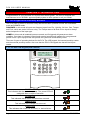
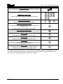
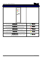
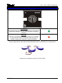
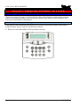
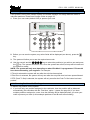
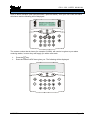
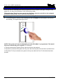
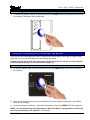
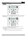
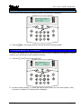
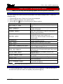
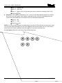
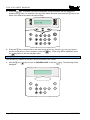
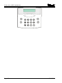
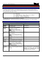
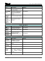
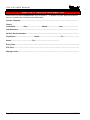
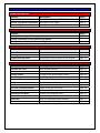
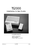
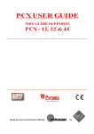
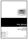
User Manual
RINS867-3
CONTENTS
CHAPTER 1: INTRODUCTION........................................................................................... 4
1.1 THE KEYPAD AND PROXIMITY READERS ..................................................................................... 4
1.1.1 The PCX LCD Keypad (PCX-LCD/UK).............................................................................. 4
1.2 THE INTERNAL READER (PCX-PROX/INT)................................................................................. 6
1.3 THE EXTERNAL READER (PCX-PROX/EXT) .............................................................................. 7
CHAPTER 2: ARMING AND DISARMING THE SYSTEM.................................................. 8
2.1 ARMING / DISARMING VIA THE KEYPAD ...................................................................................... 8
2.1.1 Arming Arm Modes Via The Keypad ................................................................................. 8
2.1.2 Disarming Arm Modes Via The Keypad............................................................................. 8
2.1.3 Arming Partitions Via The Keypad..................................................................................... 9
2.1.4 Disarming Partitions Via The Keypad ................................................................................ 9
2.1.5 Arming Partitions with Partitions Already Armed ............................................................. 10
2.1.6 Disarming After an Alarm via the Keypad ........................................................................ 11
2.2 ANTI CODE / ENGINEER RESET................................................................................................. 12
2.2.1 Engineer Reset ................................................................................................................ 12
2.2.2 Anti Code ......................................................................................................................... 13
2.3 ARMING / DISARMING VIA THE INTERNAL TAG READER ............................................................. 14
2.3.1 Arming Partitions / Arm Modes via the Internal Tag Reader............................................ 14
2.3.2 Disarming Partitions / Arm Modes via the Internal Tag Reader....................................... 15
2.4 ARMING / DISARMING VIA THE EXTERNAL TAG READER ........................................................... 15
2.4.1 Arming Partitions / Arm Modes via the External Tag Reader .......................................... 15
2.4.2 Disarming Partitions / Arm Modes via the External Tag Reader...................................... 16
CHAPTER 3: ADVANCED FUNCTIONS .......................................................................... 17
3.1 CHIME FUNCTION ..................................................................................................................... 17
3.2 OMITTING INPUTS..................................................................................................................... 17
3.2.1 Omitting Open Inputs....................................................................................................... 19
3.3 HOLD UP ALARM VIA THE KEYPAD ........................................................................................... 19
CHAPTER 4: THE MANAGER MENU .............................................................................. 21
4.1 ENTERING THE MANAGER MENU .............................................................................................. 21
4.2 EXITING THE MANAGER MENU ................................................................................................. 21
4.3 SET DATE & TIME .................................................................................................................... 22
4.4 OMIT INPUTS............................................................................................................................ 22
4.5 CHANGE CODES ...................................................................................................................... 22
4.5.1 Changing User Codes and Manager Codes .................................................................... 22
4.6 DELETING A USER CODE .......................................................................................................... 25
4.7 REVIEW LOGS.......................................................................................................................... 25
4.7.1 The Panel Log ................................................................................................................. 25
4.7.2 The Access Log ............................................................................................................... 26
4.8 PHONEBOOK............................................................................................................................ 27
4.9 WALK TEST ............................................................................................................................. 27
4.10 BELL TEST ............................................................................................................................ 28
4.11 TEST PHC COMMUNICATIONS ................................................................................................ 29
4.12 DIAL OUT MENU .................................................................................................................... 30
4.13 ALLOW ENGINEER MENU ....................................................................................................... 31
4.14 BLOCK REMOTE ARM ............................................................................................................ 31
4.15 BLOCK UDL .......................................................................................................................... 31
4.16 ENTER ANTI-CODE................................................................................................................. 31
4.17 EXIT MANAGER MODE............................................................................................................ 31
CHAPTER 5: SERVICE INFORMATION .......................................................................... 34
CHAPTER 6: CONTACT INFORMATION ........................................................................ 35
PCX 256 USER MANUAL
CHAPTER 1: INTRODUCTION
Congratulations on your purchase of a Pyronix PCX alarm system. The PCX is designed and
manufactured to our ISO9001 approved quality system to offer options to suit your needs.
1.1 The Keypad and Proximity Readers
The PCX panel is active for 24 hours a day and the two basic operation modes are DISARMED
mode and ARMED mode.
DISARMED: In this mode all inputs are disarmed, apart from Fire, Hold Up, 24 Hour, Gas, Tamper
and Fault, which are active 24 hours a day. The Tamper state of all End of Line inputs is always
active irrespective of the input type.
ARMED: In this mode all enabled inputs are armed, and if triggered will generate an alarm
condition. If an alarm is triggered, internal and external sounders will operate for a programmed
period or time. Upon expiry of this time period, the system will automatically rearm.
There are 3 types of operating devices for the PCX: The LCD keypad, the internal proximity reader
and the external proximity reader. Also note that the PCX LCD keypad also has an inbuilt prox
reader.
1.1.1 The PCX LCD Keypad (PCX-LCD/UK)
!
PCX 256.v5.e
Time
14:48 c
A
B
C
D
Tag
,/+.
JKL
POWER LED
This indicates that the reader has power. The power LED will
extinguish after a couple of seconds.
ALARM LED
This indicates that an alarm activation has occurred.
TAMPER LED
This indicates that a tamper has occurred
FAULT LED
This indicates that a fault has occurred, i.e. device fail etc.
Page: 4
!
RINS867-3
PCX 256 USER MANUAL
DISARMED LED
This will illuminate for a couple of seconds after the system
has been disarmed.
NUMERICAL BUTTONS
Used to enter user codes and program input names
DIRECTION BUTTONS
Used to select options and scroll display.
OPERATIONAL BUTTON 1
Selects items and enters sub menu indicated in master
manager menu.
Used to arm the panel if flexi-arm is enabled.
OPERATIONAL BUTTON 2
Moves forward to the next main menu item, also clears faults.
THE A KEY
Exit Manager Mode (from a main menu item)
THE B KEY
Moves backwards to the previous menu item
THE C KEY
Chime Button and displays additional information in the log
and the diagnostic functions.
THE D KEY
Moves forward to the next option, or toggles between
‘YES/NO’ choices. Enters the manager mode.
The emergency buttons for the PCX system consist of 2 buttons being pressed to activate a Hold
Up. These are the keys and. On default these are disabled to comply to PD6662. If you
wish for these to be enabled please contact your engineer.
RINS867-3
Page: 5
PCX 256 USER MANUAL
1.2 The Internal Reader (PCX-PROX/INT)
Power
Alarm
Tamper
Fault
Unset
Tag
POWER LED
This indicates that the reader has power present.
Power
ALARM LED
This indicates when an alarm activation as occurred.
Alarm
TAMPER LED
This indicates when a tamper has occurred.
Tamper
FAULT LED
This indicates when a fault has occurred, i.e. device fail etc.
Fault
DISARMED LED
This will illuminate for a couple of seconds after the system
has been disarmed.
Unset
Page: 6
RINS867-3
PCX 256 USER MANUAL
1.3 The External Reader (PCX-PROX/EXT)
POWER LED
This indicates that the reader has been found on the data bus,
and power is present. This will extinguish after a couple of
seconds.
RED LED
This can be programmed to follow an output (For example
you may want the output to illuminate when a partition is
armed). Contact your engineer for more information
The prox tags that are used with the PCX-PROX/INT and PCX-PROX/EXT are shown below:
These can be ordered as a pack of 5 (PCX-PTAG)
RINS867-3
Page: 7
PCX 256 USER MANUAL
CHAPTER 2: ARMING AND DISARMING THE SYSTEM
2.1 Arming / Disarming Via The Keypad
There are a number of ways to arm the PCX 256; either via the keypad, via the keypad proximity
reader, the internal tag reader or the external prox reader. Each involves either entering a valid
user code or presenting a valid tag/card.
2.1.1 Arming Arm Modes Via The Keypad
If the engineer has selected that the system is to be used as a Level arm system rather than a
Partition system, then you will arm the system as follows:
1. Enter your user code (default 1234) or present your card
A
B
C
D
Page: 8
RINS867-3
PCX 256 USER MANUAL
2.1.3 Arming Partitions Via The Keypad
If the system is set up as a partition system, the master manager can assign different codes to
individual partitions. Please see Change Codes on page: 22.
1. Enter your user code (default 1234) or present your card
Active Faults
Battery Fault100
A
B
C
D
Tag
,/+.
ABC
DEF
GHI
JKL
MNO
PQRS
TUV
WXYZ
SPACE
2. Before you can arm the system, any active faults will be displayed (see above), press the
key.
3. The system will allow you to arm the required arm mode.
4. Use the numeric and the k,m,n,pkeys to select the partition(s) you wish to arm and press
key. The system will start to arm. Once the system has armed, a beep will be heard and
the
the system is armed.
NOTE: The system will only arm depending on what ‘Exit Mode’ is programmed. This would
have been selected by your engineer. For example:
If Timed is selected the system will arm after the exit time has expired.
If Final Door is selected, the system will only arm after the entry/exit door has been opened/closed.
If PTS (Push To Set) is selected, the system will only arm after the Push To Set button has been
pushed.
2.1.4 Disarming Partitions Via The Keypad
To disarm any partition on the system:
1. If you have only one partition assigned to the card/code, then the partition will be disarmed
automatically (this coincides with the ‘Flexi-Arm’ option – please see page 24). If you have
multiple partitions assigned to a user, then the following will be displayed when you enter your
code or present your card (In this example partitions A and B were armed initially)
RINS867-3
Page: 9
PCX 256 USER MANUAL
Arm Partition?
(0123456789 CD)
A
B
C
D
Tag
2. Press the
,/+.
ABC
DEF
GHI
JKL
MNO
PQRS
TUV
WXYZ
SPACE
key. The system will ask which of the armed partitions you wish to disarm:
Disarm Partition?
(
AB )
A
B
C
D
Tag
,/+.
ABC
DEF
GHI
JKL
MNO
PQRS
TUV
WXYZ
SPACE
3. Use the numeric and the k,m,n,pkeys to select the partition(s) you wish to disarm and
key. The system will disarm those partitions.
press the
2.1.5 Arming Partitions with Partitions Already Armed
If for example partitions A and B are already armed, and you would like to arm partitions C and D,
you will do the following:
1. Enter your user code or present your card, the display will show which partitions are available
to arm (partitions A and B are already armed):
Page: 10
RINS867-3
PCX 256 USER MANUAL
Arm Partition?
(0123456789 CD)
A
B
C
D
Tag
2. Press nandp, and press the
,/+.
ABC
DEF
GHI
JKL
MNO
PQRS
TUV
WXYZ
SPACE
key. The system will arm partitions C and D.
2.1.6 Disarming After an Alarm via the Keypad
After an alarm, enter your user code (default 1234). The activated input will be displayed:
A
B
C
D
Alarm Silenced
Input 001
Tag
Press the
,/+.
ABC
DEF
GHI
JKL
MNO
PQRS
TUV
WXYZ
SPACE
key to reset the system.
PLEASE NOTE: If engineer restores or anti code restores are enabled you will not be able to
reset the system until a valid engineer code or anti-code has been entered.
RINS867-3
Page: 11
PCX 256 USER MANUAL
2.2 Anti Code / Engineer Reset
The system can be programmed so that it can be only fully reset by an engineer or by an anti-code
reset (ask your engineer to program this feature).
2.2.1 Engineer Reset
After an alarm activation (this example shows a personal attack), enter your user code, the alarm
will silence and the following will be displayed on the keypad:
Alarm Silenced
2 Key HU
,/+.
ABC
DEF
GHI
JKL
MNO
PQRS
TUV
WXYZ
SPACE
A
B
C
D
The display will switch between the activation that has just occurred and ‘Restore Required’.
Press the
key. The following display will be displayed:
A
B
C
D
Page: 12
RINS867-3
PCX 256 USER MANUAL
2.2.2 Anti Code
After an alarm activation (this example shows a personal attack), enter your user code, the alarm
will silence and the following will be displayed:
Alarm Silenced
Restore G12298
,/+.
ABC
DEF
GHI
JKL
MNO
PQRS
TUV
WXYZ
SPACE
A
B
C
D
The restore number that is shown (for example G12298), will need to be given to your alarm
receiving station, in return they will supply you with a reset code.
¾
¾
key.
Press the
Enter the code the ARC have given you. The following will be displayed:
RINS867-3
Page: 13
PCX 256 USER MANUAL
2.3 Arming / Disarming Via The Internal Tag Reader
Once the relevant cards/tags have been programmed into the system (see page ‘Change Codes’
page 22), you may arm and disarm via the internal tag reader.
Please note that ‘Flexi-Arm’ may need to be disabled so that the card will arm the assigned
partitions automatically. This is described on page: 24.
2.3.1 Arming Partitions / Arm Modes via the Internal Tag Reader
1. To arm the system, hold up a valid card/tag until the left UNSET LED illuminates, and remove
the card/tag. The system will begin to arm.
Power
Alarm
Tamper
Fault
Unset
Tag
NOTE: The system will only arm depending on what ‘Exit Mode’ is programmed. This would
have been selected by your engineer. For example:
If Timed is selected the system will arm after the exit time has expired.
If Final Door is selected, the system will only arm after the entry/exit door has been opened/closed.
If PTS (Push To Set) is selected, the system will only arm after the Push To Set button has been
pushed.
Page: 14
RINS867-3
PCX 256 USER MANUAL
2.3.2 Disarming Partitions / Arm Modes via the Internal Tag Reader
1. To disarm the system, hold up a valid card/tag until the UNSET LED is illuminates, and remove
the card/tag. The system will be disarmed.
Power
Alarm
Tamper
Fault
Unset
Tag
2.4 Arming / Disarming Via The External Tag Reader
Once the relevant cards/tags have been programmed into the system (see page ‘Change Codes’
page 22), you may arm and disarm via the external tag reader.
Please note that ‘Flexi-Arm’ may need to be disabled so that the card will arm the assigned
partitions automatically. This is described on page: 24.
2.4.1 Arming Partitions / Arm Modes via the External Tag Reader
1. To arm the system, hold up a valid card/tag until the left GREEN LED comes on, and remove
the card/tag.
2. Hold up the card/tag again, the system will start to arm the assigned Partition(s) / Arm Mode.
Remove the card/tag.
3. Once the assigned Partition(s) / Arm Mode have been armed, the GREEN LED will extinguish.
NOTE: The system will only arm depending on what ‘Exit Mode’ is programmed. This would
have been selected by your engineer. For example:
RINS867-3
Page: 15
PCX 256 USER MANUAL
If Timed is selected the system will arm after the exit time has expired.
If Final Door is selected, the system will only arm after the entry/exit door has been opened/closed.
If PTS (Push To Set) is selected, the system will only arm after the Push To Set button has been
pushed.
2.4.2 Disarming Partitions / Arm Modes via the External Tag Reader
1. To disarm the system, hold up a valid card/tag until the left GREEN LED comes on, and
remove the card/tag.
2. Hold up the card/tag again, the system will disarm the assigned Partition(s) / Arm Mode.
Remove the card/tag.
3. Once the assigned Partition(s) / Arm Mode have been disarmed, the GREEN LED will
extinguish after 15 seconds.
Page: 16
RINS867-3
PCX 256 USER MANUAL
CHAPTER 3: ADVANCED FUNCTIONS
3.1 Chime Function
The chime can be used for any input on the system, however the chime will only be active if the
chime attribute is selected for the input in the Engineer Menu.
The nkey can be used to select the Chime function while the system is disarmed. If enabled, a
tone will sound every time the relevant inputs are opened.
When enabled the display will show a ‘c’ on the right hand side of the keypad as shown below.
RINS867-3
Page: 17
PCX 256 USER MANUAL
3. Select the partition(s) / Arm Mode you would like to arm using the numeric and the
key.
k,m,n,pkeys. Press the
key, the following will be displayed:
4. Once the exit timer has started, Press the
Omit Inputs [001]
A
B
C
D
Tag
,/+.
ABC
DEF
GHI
JKL
MNO
PQRS
TUV
WXYZ
SPACE
5. Enter the inputs you wish to omit, for example, to omit inputs 2 and 3, enter ‘002’ and press the
key, then enter ‘003’ and press the
key. These inputs will be displayed on the bottom
line of the keypad.
Omit Inputs [003]
Input 002
A
B
C
D
Tag
,/+.
ABC
DEF
GHI
JKL
MNO
PQRS
TUV
WXYZ
SPACE
6.
Wait 10 seconds, the display will then revert back to the exit time and once the system is
armed the selected inputs will be omitted for the system.
7.
When you disarm the system, the display will show the inputs that have just been omitted.
key.
Press the
Note when you disarm the system the inputs will become active again.
Page: 18
RINS867-3
PCX 256 USER MANUAL
3.2.1 Omitting Open Inputs
If any inputs are open during the arming procedure, the following be displayed:
Arm with Fault?
Input 002
A
B
C
D
Tag
1. Press the
,/+.
ABC
DEF
GHI
JKL
MNO
PQRS
TUV
WXYZ
SPACE
key, the system will then arm with the shown input(s) omitted.
3.3 Hold Up Alarm via The Keypad
The PCX LCD keypad can be used to produce a Hold Up alarm if enabled by the engineer. If this is
enabled, you can produce a Hold Up Alarm as follows:
1. Press the and keys at the same time:
PCX 256.v5.e
Time
11.09 c
A
B
C
D
Tag
,/+.
ABC
DEF
GHI
JKL
MNO
PQRS
TUV
WXYZ
SPACE
2. An alarm will be activated. To disarm the Hold Up alarm, enter your user code (default: 1234)
or present a card/tag. The following will be displayed:
RINS867-3
Page: 19
PCX 256 USER MANUAL
A
B
C
D
Alarm Silenced
2 Key HU
Tag
3. Press the
,/+.
ABC
DEF
GHI
JKL
MNO
PQRS
TUV
WXYZ
SPACE
key to reset the display.
PLEASE NOTE: If engineer restores or anti code restores are enabled you will not be able to
reset the system until a valid engineer code or anti-code has been entered.
Page: 20
RINS867-3
PCX 256 USER MANUAL
CHAPTER 4: THE MANAGER MENU
NOTE: You can only enter the Manager Mode when the system is disarmed
4.1 Entering The Manager Menu
The PCX system has a user menu that is accessible via a master manager code. To enter the
manager menu:
1. Press the pkey once. ‘Enter Your Code’ will be displayed
2. Enter the master manager code (default 5678).
keys to scroll through the different options:
3. Use the mand
Functions
SET DATE & TIME
OMIT INPUTS?
CHANGE CODES?
REVIEW LOGS?
PHONEBOOK?
WALK TEST?
BELL TEST?
TEST PHC COMMUNICATIONS?
DIAL OUT MENU?*
ALLOW ENGR MENU?
BLOCK REMOTE ARM?
BLOCK UDL?
ENTER ANTI-CODE?
EXIT MANAGER MODE?
Press the
Description
Set / Adjust time and date for display and system
logs.
Temporary omission of 24-hour inputs whilst
system is disarmed
Program and change User and Manager codes or
tags. Also authorisation of tags for sub-partition /
access control purposes.
Panel Log: Review entries in panel log –
arm/disarm events, alarm events, etc.
Access Log*: Review entries in access log (if
facility used)
Lets you change the SMS numbers programmed
for text messaging service.
Enable detector operation to be tested
Enable system siren and strobe to be tested
Initiate a test call to the Pyronix Host Computer
(PHC) if SMS messaging in use
Allows the PCX system to connect to a PC and
allows the user to choose which option they would
like to perform
User has the facility to disable access to the
engineer menu
Blocks anyone trying to remotely arm and disarm
the system
Downloading is only allowed in Engineers Mode
Anti-Code features
Returns you to day mode. Can also be performed
by pressing the kkey.
key to enter the required function.
4.2 Exiting The Manager Menu
1. To exit the Manager Menu, make sure that you are not in a function, i.e. that you are back in
the main menu (all menu items are capitals), and press the kkey.
RINS867-3
Page: 21
PCX 256 USER MANUAL
4.3 Set Date & Time
Setting the date and time of the PCX system is vitally important as then any false alarms or
unknown activations etc can be easily recognised in the event log, which records the date and time
of each event.
keys to scroll to ‘SET DATE & TIME’. Press the
key. The following will
1. Use the mand
be displayed:
Year (00-99)
[06]
A
B
C
D
Tag
,/+.
ABC
DEF
GHI
JKL
MNO
PQRS
TUV
WXYZ
SPACE
2. Year: Enter the year, for example, for the year 2006, enter ‘06’ on the keypad and press the
key.
3. Month: Enter the month, for example, for June enter ‘06’ and press the
4. Day: Enter the date, for example, for the 2nd, enter ‘02’ and press the
key.
key.
key.
5. Hours: Enter the hour, for example, for 8pm enter ‘20’ (24 hour clock) and press the
6. Minutes: Enter the minutes, for example, for 8.30pm, enter ‘30’ and press the
key.
You will be returned to the Manager Menu.
4.4 Omit Inputs
Omitting inputs can be performed in the user menu, and works in a similar way as shown on page:
17
4.5 Change Codes
There are a total 500 user codes on the PCX256 system.
4.5.1 Changing User Codes and Manager Codes
The Change Codes function allows you to assign or change codes or cards/tags for different users,
as well as altering their options. The default code for user 1 is 1234.
1. Use the mand
be displayed:
Page: 22
keys to scroll to ‘CHANGE CODES. Press the
key. The following will
RINS867-3
PCX 256 USER MANUAL
A
B
C
D
Change User
Codes?
Tag
,/+.
ABC
DEF
GHI
JKL
MNO
PQRS
TUV
WXYZ
SPACE
2. To Change any of the user codes press the
key.
3. Enter the user number you would like to change/add and press the
key.
4. If there are asterisks in the brackets on the keypad, then a user code already exists. To delete
key.
this code press the nkey, or to select another user press the
Enter the new user code or present the card/tag up to the keypad (shown below)
Enter User Code
[******]
A
B
C
D
Tag
,/+.
ABC
DEF
GHI
JKL
MNO
PQRS
TUV
WXYZ
SPACE
5. Asterisks will appear in the brackets, indicating the code or card/tag has been accepted. Press
key.
the
6. User Type: Select the user type for this user code or card/tag:
¾ Enter ‘0’ = User Code (can access limited function in the manager menu)
¾ Enter ‘1’ = Manager Code (can access all functions in the manager menu)
¾ Press the
key.
7. User Partitions: Select the partitions that this user code or card/tag will be assigned for.
8. User Arm Options: Select the Arm option that this user code or card/tag will be used for.
¾ Enter ‘0’ = Disarm/Arm
RINS867-3
Page: 23
PCX 256 USER MANUAL
¾ Enter ‘1’ = Disarm Only
¾ Enter ‘2’ = Arm Only
¾ Enter ‘3’ = None (You may just want the code to access the manager menu only)
¾ Press the
key.
9. Flexi-Arm: If this option is selected as ‘Yes’ – then you can select which partitions you would
like to arm from the keypad. If this option is selected as ‘No’ (useful for cards/tags) then the
system will automatically arm the partitions that user has been assigned for.
¾ Enter ‘0’ = No
¾ Enter ‘1’ = Yes
¾ Press the
key.
NOTE: If a PCX-ACCESS system is installed then you will get “S/Part Access” on the screen, here
you can enter what codes/tags you can have linked with the access system, all you need to do is
enter the device number (address) and press
. You may have more than one.
10. User Name: Enter the user name using the following keys:
Page: 24
RINS867-3
PCX 256 USER MANUAL
4.6 Deleting a User Code
1. Use the mand
be displayed:
keys to scroll to ‘CHANGE CODES. Press the
key. The following will
A
B
C
D
Change User
Codes?
Tag
,/+.
ABC
DEF
GHI
JKL
MNO
PQRS
TUV
WXYZ
SPACE
2. To delete any of the user codes press the
key.
key.
3. Enter the user number you would like to delete and press the
4. If the user you have selected has asterisks in the bracket, press the nkey. The asterisks
should no longer be there or to select another user, press the
key.
4.7 Review Logs
The event log allows for up to 3000 events to be stored.
4.7.1 The Panel Log
The panel log includes all armed events, disarmed events, alarm events and system faults. It also
includes Engineer Access details.
1. Use the mand
displayed:
keys to scroll to ‘REVIEW LOGS’. Press the
key. The following will be
A
B
C
D
Panel Log?
Tag
RINS867-3
,/+.
ABC
DEF
GHI
JKL
MNO
PQRS
TUV
WXYZ
SPACE
Page: 25
PCX 256 USER MANUAL
2. Press the
key. The latest event will be displayed; more information can be attained by
pressing the nkey. For example, if the log says ‘Alarm Silenced’ then press the nkey to see
which user silenced the alarm as shown below:
A
B
C
D
User 001
Tag
,/+.
ABC
DEF
GHI
JKL
MNO
PQRS
TUV
WXYZ
SPACE
3. Press the kkey to return back to the main screen of the log. Use the ^and `keys to
key, ‘Panel Log’ will be displayed, press
scroll through the log. Once completed, press the
the
key twice to exit the manager menu.
4.7.2 The Access Log
The Access log contains all Access Control and Guard Tour events.
1. Use the mand
displayed:
Page: 26
keys to scroll to ‘REVIEW LOGS’. Press the
key. The following will be
RINS867-3
PCX 256 USER MANUAL
4.8 Phonebook
This function allows you to change the SMS telephone numbers that are programmed for the text
messaging service. The numbers will usually be programmed by your engineer. Here you will be
able to alter each of the numbers.
NOTE: The SMS facility must first be programmed by your engineer
1. Use the mand
displayed:
RINS867-3
keys to scroll to ‘PHONEBOOK’. Press the
key. The following will be
Page: 27
PCX 256 USER MANUAL
Page: 28
RINS867-3
PCX 256 USER MANUAL
Testing Bell...
A
B
C
D
Tag
,/+.
ABC
DEF
GHI
JKL
MNO
PQRS
TUV
WXYZ
SPACE
2. The bell and strobe will activate if the bell is installed correctly. Press the
the manager menu.
key to return to
4.11 Test PHC Communications
If the engineer has set up SMS text messaging then this function needs to be used.
The system will automatically carry out a test call to the PHC (Pyronix Host Computer) every two
weeks. The call is made via a premium rate number and the bill payer should be informed of the
charges. Customers who have “BT Answer 1571” enabled may have difficulty in connecting to the
PHC.
1. Use the mand
keys to scroll to ‘TEST PHC COMMUNICATIONS’. Press the
following will be displayed:
key. The
A
B
C
D
RINS867-3
Page: 29
PCX 256 USER MANUAL
Test sent to PHC
Test complete
Page: 30
A
B
C
D
RINS867-3
PCX 256 USER MANUAL
4. ‘Calling Remote PC’ will then be displayed. If the call fails, then please check your telephone
connections and modem numbers.
5. Press the
key to return back to the Manager Menu.
4.13 Allow Engineer Menu
If this function is enabled, the engineer will require authorisation from the user to access the
Engineers menu.
1. Use the mand
keys to scroll to ‘ALLOW ENGR MENU’. Press the
key.
2. Select the following:
¾ Enter ‘0’ = No – To disallow engineer access (only accessible from the manager mode)
¾ Enter ‘1’ = Yes – To allow engineer access
3. Press the
key, you will be returned to the engineer menu.
4.14 Block Remote Arm
Your alarm may be configured so that your alarm installation company or company manager can
arm or disarm the system remotely via the PC. Should you wish to block this access, select ‘Yes’
for this function.
1. Use the mand
keys to scroll to ‘BLOCK REMOTE ARM’. Press the
key.
2. Select the following:
¾ Enter ‘0’ = No – To block remote arming
¾ Enter ‘1’ = Yes – To allow remote arming
3. Press the
key, you will be returned to the engineer menu.
4.15 Block UDL
If this function is enabled, connecting to the PCX system via the PC software (upload/download
software) will be only allowed in the Engineers Mode.
1. Use the mand
keys to scroll to ‘BLOCK UDL’. Press the
key.
2. Select the following:
¾ Enter ‘0’ = No – To allow upload/download access
¾ Enter ‘1’ = Yes – To block upload/download access
3. Press the
key, you will be returned to the engineer menu.
4.16 Enter Anti-Code
This function will tell you if there are any engineer / anti-code features turned on.
You must enter your anti-code / engineer code to fully reset the system.
4.17 Exit Manager Mode
Select this option to save any changes you have made, and return to disarmed mode.
RINS867-3
Page: 31
PCX 256 USER MANUAL
APPENDIX A:
FAULTS
Device Codes
If a device on the PCX system is not installed correctly or has lost its communication with the
panel, “DEVICE FAIL” will be shown on the LCD keypad followed by a 3-figure device code. The
first digit identifies each type of device:
1
2
3
4
5
=
=
=
=
=
End Station
Keypad
Tag Reader / Door Station / RIX2
Remote Input Expander
Remote Output Expander
The digits after refer to that devices address, for example:
DEVICE FAIL 401 = means that the Remote Input Expander addressed as “01” has a problem.
Fault Indications
Fault
MODEM
FAULT
DIGI FAIL
COMM
PHC TEST
FAIL
LINE FAULT
100
ATE LINE
FAULT
ATE FAIL
COMM
ATSF 1
Path/Both
100
Page: 32
COMMUNICATION FAULTS
Description
Solution
End Station unable to communicate
Call Engineer
with Digi Modem
Call to ARC from Digi Modem
Call Engineer
DigiModem has failed.
Note: This is a communication
problem, which is rarely caused by an
equipment fault.
Unable to communicate with Pyronix Call Engineer
Host Computer.
Note: This would also result if the
telephone line had premium rate calls
blocked.
PSTN Line Fault signalled by Digi Call Engineer
Modem.
PSTN Line Fault signalled by device Call Engineer
using STU/ATE pins on End Station.
Call to ARC from device using End
Call Engineer
Station STU/ATE pins has failed.
Note: This is a communication
problem, which is rarely caused by
an equipment fault.
Signalling equipment has failed to
The control panel will automatically signal
signal on one of its paths or both of
a test on ATE output 10 – if the signalling
its path.
equipment has still failed the error
message will be displayed again. If not
everything will return to normal.
RINS867-3
PCX 256 USER MANUAL
RS-485 BUS PROBLEMS
Fault
DEVICE FAIL
xxx
485/COMMS
LOST
Keypad
display is
BLANK
Keypad
display
normal, but
KEYS
LOCKED
OUT
Description
Device on RS-485
communications bus failing
to communicate
Displayed on keypad that
has not yet established
communications with End
Station
Keypad address does not
match any keypad enabled
Solution
Call Engineer
More than one device
connected at the same
address
Call Engineer
Call Engineer
Call Engineer
DETECTION FAULTS
Fault
SAB
TAMPER
CASE
TAMPER
SIREN x
TAMPER
STROBE
TAMPER
Description
Tamper fault detected on
connection from SAB
Case tamper switch open
Monitors for German
specification fault
conditions on relay plug-on
Solution
Call Engineer
Call Engineer
Call Engineer
POWER SUPPLY PROBLEMS
Fault
BATTERY
FAULT xxx
BAT LOAD
FAIL
BATTERY
CRITICAL
MAINS FAIL
xxx
FUSE x
FAULT
LOW VOLTS
xxx
RINS867-3
Description
Battery Fuse (F4) failed,
OR Battery not present,
OR Battery volts low
Battery Load Test has
failed
Battery being disconnected
Solution
Call Engineer
Mains supply failed
Call Engineer
Call Engineer
Call Engineer
Call Engineer
Fuse identified failed,
OR Output protected by
fuse drawing excessive
current
Call Engineer
Power supply volts low
Page: 33
PCX 256 USER MANUAL
CHAPTER 5: SERVICE INFORMATION
We are sure you will be delighted with your PCX 256 Grade 3 System. For your personal reference
here is a record of the relevant service information.
Service Company…………….…………………………………………………………………………….
Date of
Installation…………….Day……………………….Month…………………Year……………………….
Site Reference……………………………………………………………………………………………….
24 Hour Service Number……………………………………………………………………………………
Keyholders…………….……………….Name…………………………………Tel………………………..
Name..……………………………….Tel……………………………………..
Entry Time…………………………………………………………………………………………….............
Exit Time……………………………………………………………………………………………………….
Manager Code…………………………………………………………………………………………...……
Page: 34
RINS867-3
PCX 256 USER MANUAL
CHAPTER 6: CONTACT INFORMATION
Address
RINS867-3
Page: 35
QUICK FIND GUIDE
OPERATING DEVICES
Function
Description
Pages
Keypad Indications
Description of keys and LEDS
Page: 4
Internal Tag Reader Indications Description of the LEDS
Page: 6
External Tag Reader Indications Description of the LEDS
Page: 7
ARMING / DISARMING
Function
Pages
Arming / Disarming via The Keypad
Page: 8
Arming / Disarming via the Internal Tag Reader
Page: 14
Arming / Disarming via the External Tag Reader
Page: 15
ADVANCED FUNCTIONS
Function
Description
Pages
Chime Function
How to enable the chime
Page: 17
Omitting Inputs
Omitting Inputs
Page: 17
Keypad Hold Up Alarm
Activating an Hold Up Alarm on the keypad
Page: 19
Function
Description
Pages
Set Date and Time
Alter the date and time
Page: 22
Omit Inputs
Omitting Inputs
Page: 22
Change Codes
Changing user and manager codes
Page: 22
Review Logs
Reviewing the panel and access logs
Page: 25
Phonebook
Entering SMS telephone numbers
Page: 27
Walk Test
Tests the inputs on the system
Page: 27
Bell Test
Tests both the bell and strobe outputs
Page: 28
Test PHC Communications
Initiate a test call to the PHC
Page: 29
Dial Out Menu
Dialling to a PC for upload/download
Page: 30
Allow Engineer Menu
Access to the engineer menu
Page: 31
Block Remote Arm
Block Arming via a PC
Page: 31
Block UDL
Block the upload/download software
Page: 31
Enter Anti-Code
Entering Anti-code or Engineer Codes
Page: 31
MANAGER MODE