1
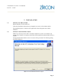
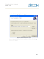
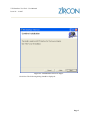
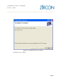
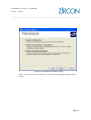
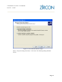
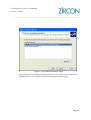
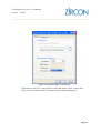
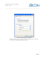
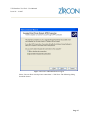
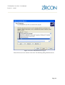
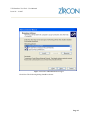
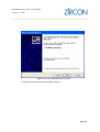
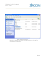
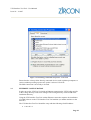
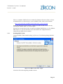
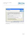
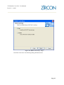
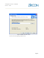
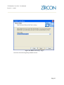
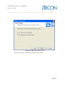
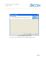
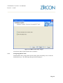
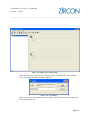
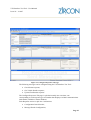
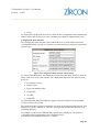
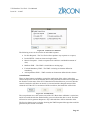
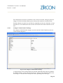
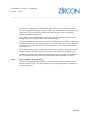
engineering your software solutions
VTS Interface Test Tool User Manual Version
1
Date
12/10/07
Prepared by
Matt Lee
ZSL Approval
Tim Wood
The contents of this document are confidential between Zircon Software Limited and VOSA. The document may not be reproduced or copied in any manner without the permission of Zircon Software Limited and VOSA. VTS Interface Test Tool - User Manual
Issue 0C - 1/10/07
engineering your software solutions
REVISION HISTORY
Issue
Date
Author
CR
Revisions
0A
14/8/07
Ben MacDonald
n/a.
Initial Revision for review
0B
25/9/07
Matt Lee
n/a.
Further revisions for review.
0C
1/10/07
Matt Lee
n/a.
Changes following review.
1
11/10/07
Matt Lee
n/a
Issued following review.
VTS Interface Test Tool - User Manual
Issue 0C - 1/10/07
engineering your software solutions
CONTENTS
1
INTRODUCTION..........................................................................................................................1
1.1
SYSTEM OVERVIEW.......................................................................................................1
1.2
RECOMMENDED CONFIGURATION............................................................................1
1.2.1 Hardware.................................................................................................................1
1.2.2 Software ..................................................................................................................1
1.3
SUPPORT ...........................................................................................................................2
2
INSTALLATION ...........................................................................................................................3
2.1
SETTING UP THE SYSTEM.............................................................................................3
2.2
INSTALLATION INSTRUCTIONS ..................................................................................3
3
CONFIGURING THE SYSTEM..................................................................................................7
3.1
INTRODUCTION...............................................................................................................7
3.2
RS232 CONFIGURATION ................................................................................................7
3.2.1 Windows XP PPP Configuration ............................................................................7
3.3
ETHERNET CONFIGURATION ....................................................................................22
3.3.1 Installing DHCP Turbo .........................................................................................23
3.3.2 Configuring DHCP Turbo.....................................................................................30
3.3.3 DHCP Configuration ............................................................................................34
4
USING THE SYSTEM ................................................................................................................35
4.1
STARTING THE SYSTEM..............................................................................................35
4.2
GUI....................................................................................................................................35
4.2.1 Menus....................................................................................................................35
4.2.2 Tab Pages ..............................................................................................................38
VTS Interface Test Tool - User Manual
Issue 0C - 1/10/07
engineering your software solutions
1
1.1
INTRODUCTION
SYSTEM OVERVIEW
The VTS Interface Test Tool provides testing functionality for the Type Approval of
Portable Devices that have been developed to be used with the MoT Computerisation
System, or more specifically the VTS Device located in MoT Test Centres.
The VTS Interface Test Tool provides the facilities that are required to comprehensively
test Portable Devices with both valid and invalid data and mimic the behaviour of the
“real” VTS Device sufficiently to gain confidence of the correct operation of the Portable
Devices under test.
The VTS Interface Test Tool enables the user to configure the data sent in the request
messages and the behaviour of the VTS Interface Test Tool in terms of the actions of the
VTS Device.
The VTS Interface Test Tool is essentially a Web Server that services HTTP requests
from a Portable Device (client).
1.2
RECOMMENDED CONFIGURATION
1.2.1
Hardware
A PC with the following hardware configuration is recommended for the VTS Interface
Test Tool:
1.2.2
•
Intel Pentium 2 1.80 Ghz CPU (or equivalent);
•
1 Gb of RAM.
Software
The following operating system is required for the VTS Interface Test Tool:
•
Windows XP Pro Service Pack 2. .Net 2.0 Framework;
•
Adobe Acrobat (or other .pdf file viewer);
•
DHCP Turbo 3.0 (or other DCHP Server software for Windows XP).
Page 1
VTS Interface Test Tool - User Manual
Issue 0C - 1/10/07
engineering your software solutions
1.3
SUPPORT
Should you be unable to find the information you need in this manual, or in the on-line
help, an additional support package may be purchased for an additional cost from Zircon
Software Limited:
Zircon Software Limited
Avon Court, Castle Street
Trowbridge, Wilts BA14 8AR
Tel: 01225 764 444
Fax: 01225 753 087
email: [email protected]
Website: www.zirconsoftware.co.uk
Page 2
VTS Interface Test Tool - User Manual
Issue 0C - 1/10/07
engineering your software solutions
2
2.1
INSTALLATION
SETTING UP THE SYSTEM
Run the Installer.exe file on the CD.
Follow the Installation instructions as prompted (see section 2.2 for further details).
The installation places a shortcut to the application in Start Programs menu within
Windows.
2.2
INSTALLATION INSTRUCTIONS
Note: If you do not have the .NET 2.0 runtime installed on your PC, the installer will
prompt you to install it. An internet connection will be required to download the .NET 2.0
runtime.
Having launched the installer a series of screens will be presented. The following dialog
should be displayed:
Figure 2.1. VTS Interface Test Tool - Page 1.
Page 3
VTS Interface Test Tool - User Manual
Issue 0C - 1/10/07
engineering your software solutions
Click Next. The following dialog should be displayed:
Figure 2.2. VTS Interface Test Tool - Page 2.
Choose a destination for the Test Tool to be installed into. Click Next. The following
dialog should be displayed:
Page 4
VTS Interface Test Tool - User Manual
Issue 0C - 1/10/07
engineering your software solutions
Figure 2.3. VTS Interface Test Tool - Page 3.
Click Next. The following dialog should be displayed:
Page 5
VTS Interface Test Tool - User Manual
Issue 0C - 1/10/07
engineering your software solutions
Figure 2.4. VTS Interface Test Tool - Page 4.
Installation is now complete.
Page 6
VTS Interface Test Tool - User Manual
Issue 0C - 1/10/07
engineering your software solutions
3
3.1
CONFIGURING THE SYSTEM
INTRODUCTION
This section discusses the different configurations of the VTS Interface Test Tool for the
two types of connection that can be made with the VTS Interface Test Tool:
•
RS232 Serial Connection;
•
Ethernet Connection.
Only one of the above connection methods should be used at a given time.
3.2
RS232 CONFIGURATION
Using the VTS Interface Test Tool with an RS232 connection requires the IP Address
used by the VTS Interface Test Tool to be configured (if changed from the default value).
In order to do this the VITTConfig.xml file in the Config directory needs to be changed.
The Config directory can be found in the installation directory.
The Config Item “ServerIPAddress” in the VITTConfig.xml file should read
“192.168.1.1”.
Windows XP also needs to be configured to accept PPP connections from the Portable
Device.
3.2.1
Windows XP PPP Configuration
Using the Start Menu (or by any other means), open the Control Panel. If the classic view
is displayed (shown below) select the Network Connections option and then the Network
Connections option. The following dialog should be displayed:
Page 7
VTS Interface Test Tool - User Manual
Issue 0C - 1/10/07
engineering your software solutions
Figure 3.1. Control Panel (Classic View).
Alternatively, if the Category View is displayed (shown below) select the Network and
Internet Connections option and then on the following page, the Network Connections
option.
Page 8
VTS Interface Test Tool - User Manual
Issue 0C - 1/10/07
engineering your software solutions
Figure 3.2. Control Panel (Category View).
The following dialog should be displayed:
Page 9
VTS Interface Test Tool - User Manual
Issue 0C - 1/10/07
engineering your software solutions
Figure 3.3. Network Connections
Click on the “Create a new connection” option under Network Tasks. The network
connection wizard should be displayed:
Page 10
VTS Interface Test Tool - User Manual
Issue 0C - 1/10/07
engineering your software solutions
Figure 3.4. New Connection Wizard - Page 1
Click Next. The following dialog should be displayed:
Page 11
VTS Interface Test Tool - User Manual
Issue 0C - 1/10/07
engineering your software solutions
Figure 3.5. New Connection Wizard - Page 2
Select “Set up an advanced connection”. Click Next. The following dialog should be
shown:
Page 12
VTS Interface Test Tool - User Manual
Issue 0C - 1/10/07
engineering your software solutions
Figure 3.6. New Connection Wizard - Page 3
Select “Accept incoming connections”. Click Next. The following dialog should be
shown:
Page 13
VTS Interface Test Tool - User Manual
Issue 0C - 1/10/07
engineering your software solutions
Figure 3.7. New Connection Wizard - Page 4
Select the option corresponding to the Serial Port that you wish to use to connect to the
Portable Device. Click Properties. The following dialog should be shown:
Page 14
VTS Interface Test Tool - User Manual
Issue 0C - 1/10/07
engineering your software solutions
Figure 3.8. Properties Dialog – General Tab
On the General Tab select a port speed of 115200 and Software Flow Control (Xon /
Xoff). Click the Advanced Tab. The following dialog should be displayed:
Page 15
VTS Interface Test Tool - User Manual
Issue 0C - 1/10/07
engineering your software solutions
Figure 3.9. Properties Dialog – Advanced Tab
Configure the Data bits to be 8, the Parity to be None, the Stop bits to be 1. Then click
Ok. Click Next. The following dialog should be shown:
Page 16
VTS Interface Test Tool - User Manual
Issue 0C - 1/10/07
engineering your software solutions
Figure 3.10. New Connection Wizard - Page 5
Select “Do not allow virtual private connections”. Click Next. The following dialog
should be shown:
Page 17
VTS Interface Test Tool - User Manual
Issue 0C - 1/10/07
engineering your software solutions
Figure 3.11. New Connection Wizard - Page 6
Ensure that no users are selected. Click Next. The following dialog should be shown:
Page 18
VTS Interface Test Tool - User Manual
Issue 0C - 1/10/07
engineering your software solutions
Figure 3.12. New Connection Wizard - Page 7
Click Next. The following dialog should be shown:
Page 19
VTS Interface Test Tool - User Manual
Issue 0C - 1/10/07
engineering your software solutions
Figure 3.13. New Connection Wizard - Page 8
Click Finish. The following dialog should be shown:
Page 20
VTS Interface Test Tool - User Manual
Issue 0C - 1/10/07
engineering your software solutions
Figure 3.14. Network Connections
Right click on “Incoming Connections”. Click Properties. Select the Users tab. The
following dialog should be shown:
Page 21
VTS Interface Test Tool - User Manual
Issue 0C - 1/10/07
engineering your software solutions
Figure 3.15. Incoming Connections Properties - Users Tab
Ensure that the “Always allow directly connected devices such as palmtop computers to
connect without providing a password” option is selected. Click Ok.
The PPP Connection is now ready to be used.
3.3
ETHERNET CONFIGURATION
In order to use the VTS Test Tool with an Ethernet connection the VITTConfig.xml file
in the Config directory needs to be changed. The Config directory can be found in the
installation directory.
Using the VTS Interface Test Tool with an Ethernet connection requires the installation
of a DHCP Server on the VTS Interface Test Tool machine (or another machine on the
network).
The VTS Interface Test Tool should be setup with the following fixed IP address:
•
192.168.2.1.
Page 22
VTS Interface Test Tool - User Manual
Issue 0C - 1/10/07
engineering your software solutions
There are a number of DHCP Servers available for Windows XP Service Pack 2. Zircon
recommends the use of the freeware version of DHCP Turbo, which can be found at:
http://www.download.com/DHCP-Turbo/3000-2085_4-10311917.html
Note: This URL may become obsolete. In which case DHCP-Turbo can be found by
searching for “DHCP Turbo” in a search engine.
The next two sections discuss how to install and configure DHCP Turbo 3.0. If a different
DHCP Server is to be used, then the section after defines the configuration that is
required for the DHCP Server machine.
3.3.1
Installing DHCP Turbo
Launch the DHCP Turbo Installer (dhcpt_std_free.exe). The following dialog should be
shown:
Figure 3.16. DHCP Turbo Setup - Page 1
Click Next. The following dialog should be shown:
Page 23
VTS Interface Test Tool - User Manual
Issue 0C - 1/10/07
engineering your software solutions
Figure 3.17. DHCP Turbo Setup - Page 2
Click “I agree to the terms of this license agreement”. Click Next. The following dialog
should be shown:
Page 24
VTS Interface Test Tool - User Manual
Issue 0C - 1/10/07
engineering your software solutions
Figure 3.18. DHCP Turbo Setup - Page 3
Click Full. Click Next. The following dialog should be shown:
Page 25
VTS Interface Test Tool - User Manual
Issue 0C - 1/10/07
engineering your software solutions
Figure 3.19. DHCP Turbo Setup - Page 4
Click Next. The following dialog should be shown:
Page 26
VTS Interface Test Tool - User Manual
Issue 0C - 1/10/07
engineering your software solutions
Figure 3.20. DHCP Turbo Setup - Page 5
Click Next. The following dialog should be shown:
Page 27
VTS Interface Test Tool - User Manual
Issue 0C - 1/10/07
engineering your software solutions
Figure 3.21. DHCP Turbo Setup - Page 6
Click Yes. Click Next. The following dialog should be shown:
Page 28
VTS Interface Test Tool - User Manual
Issue 0C - 1/10/07
engineering your software solutions
Figure 3.22. DHCP Turbo Setup - Page 7
Click Install. After some processing, the following dialog should be shown:
Page 29
VTS Interface Test Tool - User Manual
Issue 0C - 1/10/07
engineering your software solutions
Figure 3.23. DHCP Turbo Setup - Page 8
Click Finish. DHCP Turbo should now be installed.
3.3.2
Configuring DHCP Turbo
Launch DHCP Turbo (using either the start menu option, the desktop icon or from the
installed directory). The following dialog should be displayed:
Page 30
VTS Interface Test Tool - User Manual
Issue 0C - 1/10/07
engineering your software solutions
Figure 3.23. DHCP Turbo Main Dialog
Expand the options for local host by clicking on the [+] left hand side of the localhost
server. The following dialog should be displayed:
Figure 3.24. Login Dialog
There is no need to enter a Password, simply click Login. The following items should be
shown for the local host:
Page 31
VTS Interface Test Tool - User Manual
Issue 0C - 1/10/07
engineering your software solutions
Figure 3.25. DHCP Turbo Main Dialog
Right click on the Scopes and select New Scope from the resulting menu. The following
dialog should be shown:
Page 32
VTS Interface Test Tool - User Manual
Issue 0C - 1/10/07
engineering your software solutions
Figure 3.26. New Scope Dialog
Add a Name for the Scope, add a Description and choose a time for the Lease. Enter
192.168.2.129 for the start address, 192.168.2.254 for the end address and 255.255.255.0
as the Subnet mask. Click Ok.
Select Control Service from the Tools menu.
Figure 3.27. Control Service Dialog
Click Stop. The following should be shown:
Page 33
VTS Interface Test Tool - User Manual
Issue 0C - 1/10/07
engineering your software solutions
Figure 3.28. Control Service Dialog
Click Start. DHCP should now be serving IP addresses for Portable Devices.
3.3.3
DHCP Configuration
The following table defines the required configuration for DHCP on the VTS Interface
Test Tool machine/network:
Item
Configuration
Start address
192.168.2.129
End address
192.168.2.254
Subnet mask
255.255.255.0
Page 34
VTS Interface Test Tool - User Manual
Issue 0C - 1/10/07
engineering your software solutions
4
4.1
USING THE SYSTEM
STARTING THE SYSTEM
Run the “VTS Test Tool.exe” from the installed directory, the Start Menu or click on the
shortcut in the Start Programs windows menu.
4.2
GUI
The GUI of the Test Tool consists of the following functional components; one main
dialog with six tab pages, a menu bar, and a Device State Dialog activated from the menu.
The first two tabs allow the user to set data that will be used to produce the responses to
requests from a Portable Device. The other four tabs allow the user to view data sent to
and from the Portable Device. The menu bar allows file operations, access to the Device
State dialog, starting and stopping of the underlying Web Server and launching of the
Help facility. The status bar at the bottom of the screen shows the current simulated
device status (corresponding to the VTS Device simulation rules). The features are
described more fully in the sections below.
4.2.1
Menus
The following menus are available on the Test Tool:
4.2.1.1
•
File;
•
Edit;
•
Action;
•
Help.
File Menu
The VTS Interface Test Tool enables the user to save the current state of all configured
data and restore previous saved information.
To do this the File menu provides the following options:
•
Open;
•
Save;
•
Exit.
The Open option enables the user to open an existing configuration of the responses and
the device state via a standard Open File Dialog.
The Save option enables the user to save the current configuration of the responses and
device state via a standard Save File Dialog.
Page 35
VTS Interface Test Tool - User Manual
Issue 0C - 1/10/07
engineering your software solutions
The Exit option enables the user to exit the application.
4.2.1.2
Edit Menu
The Edit Menu provides one option; Device State. Clicking on the Device State option
results in the display of the Device State Configuration dialog, as shown in figure 4.1:
Figure 4.1. Device State Configuration
The Device State Configuration dialog is used to set the values that will be used to
process and validate incoming requests. The values set here are fed into business logic
rules that mimic a real VTS Device, allowing appropriate Responses to be generated for
requests.
The Device State Configuration dialog provides the user with options that enable the user
to configure the Logon Status of the simulated VTS Device. The Logon Status consists of
whether the VTS Device User has started the VTS Device (Device Started) and whether
the VTS Device User has inserted their smartcard, i.e. logged on (Smartcard Inserted).
The Device Started state is controlled by a checkbox. This equates to the Start-VTSDevice function on a VTS Device. If it is checked, then Device Started has been run. If it
is unchecked, Device Started has not been run. If the Device is not started, then no
functions will be available to the Portable Device.
The Smartcard inserted state is controlled by a checkbox. If it is checked, then the
smartcard is inserted. If it is unchecked, the smartcard is not inserted and the user is not
logged in. If the user is not logged in then the Portable Device cannot obtain Vehicle
Details.
Page 36
VTS Interface Test Tool - User Manual
Issue 0C - 1/10/07
engineering your software solutions
The Device State Configuration dialog also enables the user to enter a test number and
activate/deactivate the current test. If there is no active test then the Portable Device
cannot upload test results.
Note: The configuration of the Test Number can either be a valid or invalid number
(according to the xml schemas for the responses). This enables the user of the VTS
Interface Test Tool to test the Portable Device under both valid and invalid conditions.
The Device State Configuration dialog also enables the user to enter an Interface Version,
Documents Version and RFR Version.
Note: These parameters are used by the VTS Device simulation rules to determine the
errors that the VTS Device will generate in response to requests from a Portable Device.
Note that these errors may be overridden on the Configure Responses Tab page if
required. Also note that once again these fields can be configured to be valid or invalid.
The Device State Configuration dialog provides the user with Undo and Apply buttons.
When the user changes the Device State both buttons are enabled.
When the user clicks the Apply button the user is asked whether they would like the
changes to be propagated to the responses (on the Configure Responses tab page), in the
case of the Request Validation Parameters, or the vehicle details, in the case of the test
number. The changes made by the user to the Device State are saved as the current state
of the VTS Device.
When the user clicks the Undo button the Device State is reverted to the last saved
Device State.
4.2.1.3
Action Menu
The Action Menu provides the user with 2 options:
•
Start Server;
•
Stop Server.
The Start Server option enables the user to start the underlying Web Server that serves the
requests from a connected Portable Device.
The Stop Server option enables the user to stop the underlying Web Server that serves the
requests from a connected Portable Device. When the Server is stopped the VTS Interface
Test Tool will not respond to requests from the Portable Device.
Note: The VTS Interface Test Tool opens in the stopped state. Consequently, the User
should action the Start Server option prior to commencing testing.
4.2.1.4
Help Menu
The Help Menu provides the User with the following options:
•
Help;
Page 37
VTS Interface Test Tool - User Manual
Issue 0C - 1/10/07
engineering your software solutions
•
About.
Upon the action of the Help option, Adobe Acrobat (or another .pdf file viewer) is
displayed with this User Manual.
Upon the action of the About option an About dialog is displayed, as shown in figure 4.2
below:
Figure 4.2: About Dialog
4.2.2
Tab Pages
The following sections describe the behaviour of each of the tab pages:
4.2.2.1
Configure Responses Tab Page
The Configure Reponses tab page, as shown in figure 4.3, provides the user with the
facilities that enable the configuration of messages that are sent to the connected Portable
Device in response to requests. The responses to the three different potential requests
from the Portable Device can be configured individually.
Page 38
VTS Interface Test Tool - User Manual
Issue 0C - 1/10/07
engineering your software solutions
Figure 4.3. Configure Responses Tab Page
The following messages can be configured using the VTS Interface Test Tool:
•
Check Status response;
•
Get Vehicle Details response;
•
Upload Test Results response.
The Configure Responses Tab page is split horizontally into 4 sections; one
corresponding to each response type and another that displays real-time communications
information (called the Comms Window).
Each Response section is split into 3 subsections:
•
Configuration Item Selection;
•
Message Header Configuration;
Page 39
VTS Interface Test Tool - User Manual
Issue 0C - 1/10/07
engineering your software solutions
•
Errors.
For each of the responses the user can set values for the Configuration Items and Message
Header values, and can choose to cause a number of predefined communication errors.
Configuration Item Selection
The Configuration Item Selection control allows the user to set the values used in the
<ConfigurationItems> section of a response. Not all items may be relevant to a particular
response type.
Figure 4.4. Configuration Items Control (Check Status)
For Check Status Responses, the control has six text boxes that allow the user to enter the
string values to be used in the response. For Check Status responses, the values that can
be set are:
•
Documents Version;
•
RFR Version;
•
Inspection Manuals URL;
•
Guide URL;
•
SN URL;
•
RFR URL.
For Vehicle Details and Upload Results responses only Documents Version and RFR
Version text boxes are present.
The configured URLs should correspond to a location on the target machine that the VTS
Interface Test Tool is running on. All URLs are targeted at the Webroot directory in the
installation directory.
For example, a URL for the “HHDGUIDE_2007050301_000001.zip” file located in
“c:\Program Files\Zircon Software Ltd\VTS Interface Test
Tool\Webroot\vimot\hhd\Synchronise”, would be:
Page 40
VTS Interface Test Tool - User Manual
Issue 0C - 1/10/07
engineering your software solutions
/vimot/hhd/Synchronise/HHDGUIDE_2007050301_000001.zip
If the specified URL does not correspond to an existing file then the VTS Interface Test
Tool will send an HTTP error to the Portable Device.
Note: Configuring the Documents Version or RFR Version will not affect the algorithms
that determine what the errors should sent be in response to the request (as these are
determined by the Device State). If the user wishes to control these errors then the User
should override the errors configuration for the particular response or use the Device
State to change the Documents and/or RFR Versions to generate the desired errors. If the
Device State versions are different from the response configuration, then the differences
are indicated in yellow on the screen.
Note: Also note that the RFR Version and Document Version can be configured to either
be consistent with the response schemas or not in order to test the correct behaviour of the
Portable Device under error conditions.
Message Header Configuration
The Message Header Configuration control allows the user to set general message header
values, including the reported errors. The values set here are the ones that will be reported
back to the Portable Device in a Response message, they are not used to validate the
incoming requests.
The Interface version text box enables the user to set the Interface Version that will be
used. If the value for the Interface Version is different from the Device State Interface
Version that is used for determining the responses to requests then the Interface Version
is highlighted in Yellow.
The Override Service Name check box allows the user to change the service name in the
response to be different to the valid default. If this box is checked then the adjacent text
box becomes active. This allows the user to enter an alternative service name, which may
be a Service Name of another response or completely invalid.
Figure 4.5. Message Header Configuration Control – No Errors
Page 41
VTS Interface Test Tool - User Manual
Issue 0C - 1/10/07
engineering your software solutions
The Generate Errors checkbox allows the user to insert error elements into the response
XML. If errors are activated here then they will override and replace any real errors that
would have been generated by the VTS Device simulation rules.
Figure 4.6. Message Header Configuration Control – With Errors
When the checkbox is checked, a data entry table becomes visible. This allows the user to
enter error data. Data entry is free form; it is not necessary to fill in all cells for a row. If
all data for a row is deleted, the user will be asked if they wish to delete the row.
Answering “No” will set a row of empty error data.
Error Generation
The Errors control allows the user to cause comms errors in the Response message.
Figure 4.7. Comms Errors Disabled
If the Enable Comms Errors checkbox is unselected, then the Test Tool will respond to
requests appropriately based on the values set elsewhere. If the checkbox is checked then
the radio buttons will be enabled. These allow the user to select from a number of
predefined communications errors.
Page 42
VTS Interface Test Tool - User Manual
Issue 0C - 1/10/07
engineering your software solutions
Figure 4.8. Comms Errors Enabled
The following errors can be sent for an individual response:
•
Do Not Respond – The Test Tool will not produce any response to a request;
•
Invalid HTTP – Sends an incorrect length value;
•
Massive Response – Sends a response that contains a considerable amount of
data;
•
Malform XML – The XML is invalid due to missing tags;
•
Exclude Mandatory XML – The XML is missing an element defined as
mandatory;
•
Add superfluous XML – XML contains an element not defined in the schema.
Action Buttons
There are three buttons available to control the application of the values in the three
controls. Responses sent to the Portable Device are generated from the last accepted data,
not from the current state of the GUI. If data has been altered but not yet saved, then the
control’s header bar will have an asterisk (*) inserted and the changed section will be
coloured red. If the GUI is consistent with the saved data, the header bar will be blue.
Figure 4.9. Action Buttons
The Accept button saves the current state of the GUI. Basic data validation is carried out,
and if successful the title bar flashes briefly green to indicate the data is saved. This data
will now be used to generate Responses. Any red header bars will be returned to blue.
The Preview button opens a window showing the XML Response Message that would be
generated by the current saved data.
Page 43
VTS Interface Test Tool - User Manual
Issue 0C - 1/10/07
engineering your software solutions
The Undo button resets the User Interface to the current saved state, losing any unsaved
changes. The title bar briefly flashes green, and any red controls are returned to blue.
The three buttons are made active and inactive depending on the state of the data. Accept
and Undo are not available unless the current GUI state has been altered from the saved
state.
4.2.2.2
Configure Vehicle Details Tab Page
The configure Vehicle Details tab page is used to enter the Vehicle Details used in Get
Vehicle Details Responses.
Figure 4.10. Configure Vehicle Details Tab Page
A single Property Grid contains all the relevant data. Individual items may be expanded
by clicking on the [+] icon at the side of each row. Values can be entered as either a free
text string, or a selection from a drop down menu, depending on the data type.
Page 44
VTS Interface Test Tool - User Manual
Issue 0C - 1/10/07
engineering your software solutions
Each item has a displayed and displayName attribute that can be used by the Portable
Device to configure the display of vehicle details. The Value attribute corresponds to the
value that is to be set for the item. Where more than one piece of data is pertinent
additional attributes are displayed.
The Configure Vehicle Details tab provides Undo and Accept buttons that are used to
manage the current configured state of the Vehicle Details.
The Accept button saves the current state of the GUI. Basic data validation is carried out,
and if successful the title bar flashes briefly green to indicate the data is saved. This data
will now be used to generate Get Vehicle Data Responses. Any red header bars will be
returned to blue.
The Undo button resets the User Interface to the current saved state, losing any unsaved
changes. The title bar briefly flashes green, and any red controls are returned to blue.
The buttons are made active and inactive depending on the state of the data. The buttons
are not available unless the current GUI state has been altered from the saved state.
4.2.2.3
Received Header Details Tab Page
The Received Header Details tab page shows the contents of the last request received
from the Portable Device. The data is displayed in a property grid and is not editable, as
shown in figure 4.11:
Page 45
VTS Interface Test Tool - User Manual
Issue 0C - 1/10/07
engineering your software solutions
Figure 4.11. Received Header Details Tab Page
Individual items may be expanded by clicking on the [+] icon at the side of each row.
4.2.2.4
Received Test Results Tab Page
The Received Test Results tab shows the contents of the last Upload Test Results request
sent from the Portable Device. The data is displayed in a property grid and is not editable,
as shown in figure 4.12.
Page 46
VTS Interface Test Tool - User Manual
Issue 0C - 1/10/07
engineering your software solutions
Figure 4.12. Received Test Results Tab Page
Individual items may be expanded by clicking on the [+] icon at the side of each row.
4.2.2.5
Test Log Tab Page
The Test Logs tab displays trace messages describing what actions and events have taken
place, as shown in figure 4.13:
Page 47
VTS Interface Test Tool - User Manual
Issue 0C - 1/10/07
engineering your software solutions
Figure 4.13. Test Log Tab Page
The Messages in the Test Log provide a historical log of the events that the VTS Interface
Test Tool has been subject to since the log was last cleared or since the tool started.
Colour coding is used to indicate different types of events, as defined by the table below:
Colour
Meaning
Green
This corresponds to communications events that are correct under
normal operating conditions. Examples include indications that valid
requests have been received, indications that responses have been sent
and changes in the status of the Communications with the Portable
Device.
Black
This corresponds to general information. This includes information
such as unexpected mismatches in data (e.g. the Documents Version in
a request being different to the Device State).
Page 48
VTS Interface Test Tool - User Manual
Issue 0C - 1/10/07
engineering your software solutions
Red
This is used to indicate errors in the received data, for instance Schema
Validation Problems.
Blue
This is used to indicate that there has been a potential problem
validating Brake Data received from the Portable Device (validation is
carried out in accordance with the Criteria Specification in order to test
the correct operation of the Portable Device).
Dark Red
This is used to indicate that there has been a problem validating the
brake data (validation is carried out in accordance with the Criteria
Specification in order to test the correct operation of the Portable
Device).
The messages contained in this log are not editable.
Right clicking on the Test Log data results in a menu that contains two options:
•
Clear All;
•
Word wrap.
The Clear All option clears all of displayed Test Log messages.
The Word wrap option switches word wrap on so that lines of text that are too long are
wrapped onto the next line.
4.2.2.6
Comms Log Tab Page
The Comms Log tab page displays to the user the content of all messages between the
Test Tool and the Portable Device. There are two separate panes; the top pane shows
messages received from the Portable Device; the bottom pane shows the messages sent to
the HHD. Communications Log messages are shown as an unformatted XML string as
shown in the figure 4.14:
Page 49
VTS Interface Test Tool - User Manual
Issue 0C - 1/10/07
engineering your software solutions
Figure 4.14. Comms Logs Tab Page
Right clicking on the Test Log data results in a menu that contains two options:
•
Clear All;
•
Indent XML.
The Clear All option clears all of displayed Test Log messages.
The Indent XML option formats the displayed XML so that it may be more easily read.
[End Of Document]
Page 50