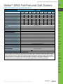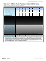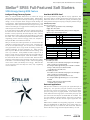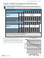
1
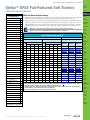
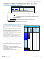
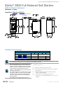
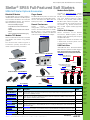
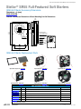
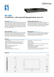
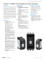
Prices as of April 15, 2015. Check Web site for most current prices.
Stellar® SR55 Full-Featured Soft Starters
Overview
SR55 full-featured solid-state Soft Starters
provide many advantages when used
instead of electromechanical contactors to
control 3-phase AC induction motors. The
SR55 Soft Starters are fully digital, and use
thyristors in all three motor phases for
controlled reduced voltage motor starting
and stopping. SR55s have an Automatic
Application Setup that fully configures the
starter for a specific application with one
entry. SR55s also have a built-in internal
bypass and patented iERS (intellegent
Energy Recovery System) that reduces
energy costs when used on lightly loaded
and oversized motors.
Features
• 17–477A @ 200–480VAC
• 24VDC, 110VAC, or 230VAC selectable
control voltage
• Internally bypassed during run
• Full three-phase motor control
• Built-in SCR failure protection
• Full motor overload protection
• Full data logging (fault records, motor
current, operational status, etc.)
• Fully programmable
• Easily and separately adjustable motor
start and stop times
• iERS (intelligent Energy Recovery System)
saves energy on lightly-loaded motors
• Can be connected ‘in-the-delta’, allowing
use of a smaller Soft Starter (no iERS
optimizing with in-delta connections)
• Can be used for motor reversing (with
external contactors)
• Suitable for a wide variety of motor loads
• Touchscreen with easy-to-navigate menu
structure and quick automatic application
set up
• Can be used with local or remote control
• Integrated Modbus RTU, or optional
Modbus TCP or EtherNet/IP communication
• Optional remote touchscreen available
• Programmable analog I/O, digital inputs,
and relay outputs for remote control
• Fault record history of last 10 trips (using
the download fault log will give faults and
running data for the life of the SR55)
• IP20, panel mount with optional finger
guards for frame sizes 1 and 2 soft starters
• Two-year warranty
• CE, ETL (CSA C22.2 No.14 and UL 508),
REACH, RoHS
Advantages
Mechanical Advantages
• Smaller physical size than equivalent SR44
models (even with the built-in bypass
contactors)
• Smooth acceleration; reduced mechanical
shock and starting stress
• Extend lifespan of mechanical drive-train
components
• Fluid couplings and some clutches can be
eliminated
Electrical Advantages
• Reduced starting currents and spikes
• More motors or larger motors can be
started from lower-capacity power sources
• Allows motors to be started more
frequently
Economic Advantages
• Lower overall costs for new installations
• Bypass relays built in
• Reduced maintenance and replacement of
mechanical drive-train components
• Reduced starting current lowers demand
charges
• iERS (intelligent Energy Recovery System)
reduces electrical power costs
• Automatic Application setup feature
speeds installation by configuring the SR55
for a specific application with one setting
Optional accessories
• EtherNet/IP communication module
• Modbus TCP communication module
• Modbus serial communication splitter
• RJ12 to RJ45 adapter
• Power terminal IP20 finger guards
• Remote touchscreen
• Replacement touchscreen
• Replacement cooling fans
Applications
• General purpose applications where
traditional across-the-line starting or
wye-delta starting would typically be
appropriate
• Applications with oversized or lightly
loaded motors (iERS reduces energy usage)
• Applications requiring lower inrush
currents
Book 2 (14.1)
eSS-20
Soft Starters
1-800-633-0405
Prices as of April 15, 2015. Check Web site for most current prices.
Stellar® SR55 Full-Featured Soft Starters
Company
Information
SR55 Soft Starter Technical Specifications
Drives
Soft Starters
SR55 Series Full-Featured Soft Starters – 17A–96A *
SR55
-017
SR55
-021
SR55
-027
SR55
-034
SR55
-040
1
SR55
-052
SR55
-065
SR55
-077
SR55
-096
$975.00
$982.00
$985.00
$1,065.00
$1,120.00
$1,258.00
$1,318.00
$1,527.00
$1,575.00
17
21
27
34
40
52
65
77
96
3
5
7.5
10
10
15
20
20
30
* Motor Rating @ 208V (hp)
5
5
7.5
10
10
15
20
25
30
* Motor Rating @ 230V (hp)
5
5
7.5
10
10
15
20
25
30
* Motor Rating @ 460V (hp)
10
15
20
25
30
40
50
60
75
Model
Frame Size
Price
* Rated Current Ie (A)
Rated Operational Voltage
* Motor Rating @ 200V (hp)
200VAC to 480VAC
Trip Class
Index Rating [per IEC 60947-4-2]
Impulse Withstand Voltage
Insulation Voltage Rating
Short Circuit Current Rating (type 1) (kA)
Control Power Consumption
Control Voltage Range
Control Fuse (external)
Control Inputs
Control Outputs
** Start Time Setting Range (s)
Start Voltage Setting Range (%)
** Stop Time Setting Range (s)
Ambient Operating Temperature
Transportation & Storage Temperature
Humidity
Maximum Altitude
Environmental Rating
Weight (lb [kg])
*** Agency Approvals
programmable 10 to 30
Motors
Power
Transmission
Motion: Servos
and Steppers
Motor Controls
Sensors:
Proximity
Sensors:
Photoelectric
Sensors:
Encoders
Ie: AC-53a: 3.5–17: 90–5
4kV
Sensors:
Limit Switches
480V
5
Sensors:
Current
10
60W inrush to latch internal bypass relays; 4W steady state
Sensors:
Pressure
24VDC +10%-15% or 110–230VAC +10%-15%
4A
(3) DI @ 24VDC, 110VAC, or 230VAC; (1) PTC Thermistor; (1) AI @ 0–10VDC 10mA max or 4–20mA
(3) N/O relay and (1) N/C relay @ 30VDC 0.5A / 230VAC 1A resistive; (1) AO @ 0–10VDC 10mA max or 4–20mA
Sensors:
Temperature
Sensors:
Level
1 to 300
10 to 100
0 to 300
-20°C [-4°F] to 50°C [122°F] ; above 50°C derate linearly by 4% of SR55 Ie per °C to a maximum of 60°C (140°F)
-20°C to 60°C [-4°F to 140°F] continuous
max 85% non-condensing, not exceeding 50% @ 40°C [104°F]
1,000m [3,281ft] ; above 1000m derate by 1% of SR55 Ie per 100m (328ft) to a maximum altitude of 2000m (6562ft)
Main Circuit: IP00 (IP20 with optional finger guards for sizes 1&2 only); Control Circuit: IP20
No corrosive gases permitted
6.6 [3.0]
7.7 [3.5]
CE, CSA C22.2 No.14 (ETL tested), ETL 4004274, REACH, RoHS, UL508 (ETL tested)
* Refer to Selection Table for deratings by application and overload trip class.
** Start Time and Stop Time define the length of time the soft starter varies the voltage to the motor. While a Variable Frequency Drive (AC Drive) can define
motor speed throughout the acceleration and deceleration ramps by varying its output frequency, a soft starter only controls average voltage to the motor and
cannot accurately control motor speed. Therefore, motor speed during acceleration and deceleration can vary with load. Example: a conveyor soft starter
could have a Start Time of 10s. If the conveyor is empty, the motor may actually reach top speed in 8s. If the conveyor is heavily loaded, the motor may not
reach full speed until 10s. For more information, please see the SR55 User Manual - “Appendix B: Soft Starter Application Considerations.”
*** To obtain the most current agency approval information, see the Agency Approval Checklist section on the specific part number’s web page.
Sensors:
Flow Switches
Pushbuttons
and Lights
Stacklights
Signal
Devices
Process
Relays and
Timers
Pneumatics:
Air Prep
Pneumatics:
Directional Control
Valves
Pneumatics:
Cylinders
Pneumatics:
Tubing
Pneumatics:
Air Fittings
Appendix
Book 2
Terms and
Conditions
Book 2 (14.1)
www.automationdirect.com/soft-starters
Soft Starters
eSS-21
Prices as of April 15, 2015. Check Web site for most current prices.
Stellar® SR55 Full-Featured Soft Starters
SR55 Soft Starter Technical Specifications
SR55 Series Full-Featured Soft Starters – 124A–477A *
Model
SR55-124 SR55-156 SR55-180 SR55-242 SR55-302 SR55-361
Frame Size
Price
* Rated Current Ie (A)
Rated Operational Voltage
* Motor Rating @ 200V (hp)
2
SR55-414
SR55-477
3
$1,605.00
$2,465.00
$2,660.00
$2,784.00
$2,833.00
$3,422.00
$4,184.00
$4,725.00
124
156
180
242
302
361
414
477
200VAC to 480VAC
40
50
60
75
100
125
150
150
* Motor Rating @ 208V (hp)
40
50
60
75
100
125
150
150
* Motor Rating @ 230V (hp)
40
60
60
75
100
150
150
150
* Motor Rating @ 460V (hp)
100
125
150
200
250
300
350
400
Trip Class
programmable 10 to 30
Index Rating [per IEC 60947-4-2]
Impulse Withstand Voltage
Insulation Voltage Rating
Short Circuit Current Rating (type 1)(kA)
Control Power Consumption
Control Voltage Range
Control Fuse (external)
Control Inputs
Control Outputs
** Start Time Setting Range (s)
Start Voltage Setting Range (%)
** Stop Time Setting Range (s)
Ambient Operating Temperature
Transportation & Storage Temperature
Humidity
Maximum Altitude
Environmental Rating
Weight (lb [kg])
*** Agency Approvals
Ie: AC-53a: 3.5–17: 90–5
Ie: AC-53a: 3.5–17: 90–3
4kV
480V
10kA
18kA
60W inrush to latch internal bypass relays; 4W steady state
120W inrush; 4W steady state
24VDC +10%-15% or 110–230VAC +10%-15%
110VAC +10%-15%
4A
(3) DI @ 24VDC, 110VAC, or 230VAC; (1) PTC Thermistor; (1) AI @ 0–10VDC 10mA max or 4–20mA
(3) N/O relay and (1) N/C relay @ 30VDC 0.5A / 230VAC 1A resistive; (1) AO @ 0–10VDC 10mA max or 4–20mA
1 to 300
10 to 100
0 to 300
-20°C [-4°F] to 50°C [122°F] ; above 50°C derate linearly by 4% of SR55 Ie per °C to a maximum of 60°C (140°F)
-20°C to 60°C [-4°F to 140°F] continuous
max 85% non-condensing, not exceeding 50% @ 40°C [104°F]
1,000m [3,281ft] ; above 1000m derate by 1% of SR55 Ie per 100m (328ft) to a maximum altitude of 2000m (6562ft)
Main Circuit: IP00 (IP20 with optional finger guards for sizes 1&2 only); Control Circuit: IP20
12.1 [5.5]
14.3 [6.5]
35.3 [16.0]
CE, CSA C22.2 No.14 (ETL tested), ETL 4004274, REACH, RoHS, UL508 (ETL tested)
46.7 [21.2]
CE, REACH, RoHS
* Refer to Selection Table for deratings by application and overload trip class.
** Start Time and Stop Time define the length of time the soft starter varies the voltage to the motor. While a Variable Frequency Drive (AC Drive) can define motor speed
throughout the acceleration and deceleration ramps by varying its output frequency, a soft starter only controls average voltage to the motor and cannot accurately
control motor speed. Therefore, motor speed during acceleration and deceleration can vary with load. Example: a conveyor soft starter could have a Start Time of 10s.
If the conveyor is empty, the motor may actually reach top speed in 8s. If the conveyor is heavily loaded, the motor may not reach full speed until 10s. For more information, please see the SR55 User Manual - “Appendix B: Soft Starter Application Considerations.”
*** To obtain the most current agency approval information, see the Agency Approval Checklist section on the specific part number’s web page.
Book 2 (14.1)
eSS-22
Soft Starters
1-800-633-0405
Prices as of April 15, 2015. Check Web site for most current prices.
Stellar® SR55 Full-Featured Soft Starters
SR55 Energy-Saving iERS Feature
Company
Information
Drives
Intelligent Energy Recovery System
How Much Will iERS Save?
Soft Starters
iERS is an advanced SR55 feature that can reduce the energy
consumed by lightly-loaded (or oversized) motors. iERS matches
the power consumption to the load by monitoring and regulating
voltage, current, and power factor during the motor starting and
running stages. iERS automatically bypasses itself when it is not
needed (as the motor approaches full load torque/current), and
continues monitoring to re-engage itself as needed (as the required
motor torque/current decreases).
The savings realized by using iERS will vary by application, how
heavily the motor is loaded, and the losses internal to the motor.
While these factors can be difficult to quantify, the following estimating tools and examples may help predict your potential savings:
Motors
In its most basic function, iERS reduces the voltage being fed to
the motor when the motor does not need it. While the torque (and
therefore current) required by the load stays the same, reducing
the voltage to the motor reduces excess magnetizing current inside
the motor. For a more detailed explanation of how iERS reduces
magnetizing current and saves energy, please see “Chapter 4:
Principles of IERS” in the SR55 User Manual.
Many, if not most, AC motor applications are oversized when the
motor FLA is compared to actual running current. Oversizing can
be due to non-optimal design, but can also occur intentionally:
many applications need a larger motor for starting reasons, for
available headroom, for future expansion, etc. Other applications may have different motor demands based on loading; think
of an “up” escalator. A fully-loaded escalator requires a lot of
torque (current), while an empty escalator requires significantly less
torque (current) to maintain speed. When the escalator is empty,
the motor will not draw as much current as its FLA. When the SR55
senses this reduced torque load, the starter will reduce the voltage
to the motor. This reduced voltage results in reduced magnetizing
current in the motor (and thereby saves energy). Note that the
current required by the load stays the same; only magnetizing
current is reduced.
Estimating Energy Savings
Basis for estimations:
• 3-phase squirrel cage induction motor, standard type.
• Supply: 380 to 440V, 50Hz.
• Supply voltage > minimum working voltage on motor rating plate.
• Operation 30% rated nameplate full load.
Energy Savings Estimations – Table 1
4-Pole Motor Size kW HP Estimated Savings (% rated kW)
Less than
More than
5
22.5
55
110
110
7.5
30
75
150
150
10
6.5
3.5
2.5
1.5
-0.5
0
0.5
1
Motor Controls
Sensors:
Proximity
Sensors:
Photoelectric
Sensors:
Encoders
Sensors:
Current
0.5
2
3.3
5
-0.5
0
0.5
1
1) 37.5 kW 4-pole motor
From Table 1, use the estimated savings figure for the next higher
rating, i.e. 55 kW = 3.5% of full rated kW.
The savings would be approximately 3.5% x 37.5 kW = 1.3125 kW.
Savings % = kW saved / (30% loaded motor kW)
= 1.3125 kW / (30% x 37.5 kW) = 12%.
2) 37.5 kW 2-pole motor
From Table 1, use the estimated savings figure for the next higher
rating, i.e. 55 kW = 3.5% of full rated kW.
From Table 2, apply the pole-number factor of -0.5 %.
The savings would be approximately (3.5 % - 0.5 %) x 37.5 kW =
1.125 kW.
Savings % = kW saved / (30% loaded motor kW)
= 1.125 kW / (30% x 37.5 kW) = 10%.
Real-world applications:
iERS has been installed in many pump-jack applications (for oil
drilling, etc.). The cycle of a pump jack is extreme; for part of the
cycle the pump requires near-full torque. In the other part of the
cycle, the pump jack is very lightly loaded. In this extreme application, iERS reduced average power consumed by the pump jack
(over 30-minute intervals) from 23.99kW down to 19.85kW. This
is a 17% reduction in consumed power. Again, this is an extreme
example and is not indicative of what a typical application may
save.
iERS has been installed on metal grinding equipment. A machine
that was retrofitted with an iERS starter had a 75hp motor on a
spindle that typically ran at about 20–30% of full load. iERS was
able to reduce the energy consumed by this motor by 13–15%.
Book 2 (14.1)
Soft Starters
Sensors:
Pressure
Sensors:
Temperature
Sensors:
Level
Examples of estimated savings:
www.automationdirect.com/soft-starters
Motion: Servos
and Steppers
Sensors:
Limit Switches
Energy Savings Modifying Factors – Table 2
Motor Poles
Motor Slip
Number of Poles Add (% kW) % Slip Add (% kW)
2
4
6
8
Power
Transmission
eSS-23
Sensors:
Flow Switches
Pushbuttons
and Lights
Stacklights
Signal
Devices
Process
Relays and
Timers
Pneumatics:
Air Prep
Pneumatics:
Directional Control
Valves
Pneumatics:
Cylinders
Pneumatics:
Tubing
Pneumatics:
Air Fittings
Appendix
Book 2
Terms and
Conditions
Prices as of April 15, 2015. Check Web site for most current prices.
Stellar® SR55 Full-Featured Soft Starters
SR55 Soft Starter Overcurrent Protection
Customer-supplied external power-circuit isolation devices (contactors, disconnect switches, fusible disconnects,
shunt-trip circuit breakers, etc.) and short-circuit protection devices (circuit breakers, fuses, etc.) are required for use
with SR55 soft starters.
External Short-Circuit Protection Required for SR55
SR55 SR55 SR55 SR55 SR55 SR55 SR55 SR55 SR55
-017 -021 -027 -034 -040 -052 -065 -077 -096
SR55 Model Number
Rated Operational Current
Ie
Rating
Class J High-Speed Current-Limiting Fuse #2
21
27
#3
Rated Conditional Short-Circuit Current
UL Listed Inverse Time-Delay Circuit Breaker
#3
Rated Conditional Short-Circuit Current
96
100
160
160
160
200
200
250
315
45
60
70
90
110
125
150
175
Rating Z2 (A)
30
40
50
60
70
100
125
150
175
60
60
60
60
60
150
150
250
Rating
#3
77
30
(kA)
5
(A)
124
156
180
242
Mersen 6,9 URD 31xx
Bussmann 170M40xx
Bussmann 170M41xx
Bussmann 170M42xx
SIBA 20 61xx
(A)
302
361
414
477
550
550
700
800
900
Rating Z1
250
350
400
500
600
600
Rating Z2 (A)
225
300
350
450
500
500
600
600
Rating Z3 (A)
350
450
500
700
800
1000
1000
1000
(kA)
10
–
Mersen 6,9 URD 33xx
Bussmann 170M60xx
Bussmann 170M61xx
Bussmann 170M62xx
SIBA 20 63xx
400
Iq
300
10
SR55 SR55 SR55 SR55 SR55 SR55 SR55 SR55
-124 -156 -180 -242 -302 -361 -414 -477
Type
Class J High-Speed Current-Limiting Fuse
65
100
Ie
#2
52
(A)
SR55 Model Number
Semiconductor Fuse
(class aR) #1
40
Rating Z1 (A)
Iq
Rated Operational Current
34
Mersen 6,9 URD 30xx
Bussmann 170M30xx
Bussmann 170M31xx
Bussmann 170M32xx
SIBA 20 61xx
UL Listed Inverse Time-Delay Circuit Breaker #3 Rating Z3 (A)
Class J Time-Delay Fuse
17
Type
Semiconductor Fuse
(class aR) #1
Class J Time-Delay Fuse
(A)
1000
1100
–
n/a
18
#1 Correctly selected semiconductor fuses can provide additional protection against damage to the SR55 unit (this is sometimes referred to as type 2
coordination). These semiconductor fuses are recommended to provide this increased protection.
#2 Suitable for use in a circuit capable of delivering not more than Iq rms Symmetrical Amperes, when protected by Class J high-speed current-limiting 600V-rated
fuses with a maximum trip rating of Z1 (IEC Type 1 coordination short-circuit protection).
#3 Suitable for use in a circuit capable of delivering not more than Iq rms Symmetrical Amperes, 480 Volts maximum, when protected by Class J time delay fuses
with a maximum rating of Z2, or by a circuit breaker with an interrupting rating not less than Z3 rms Symmetrical Amperes, 480 Volts maximum as in table.
SR55 Soft Starter Overload Trip
Motor overload 'cold' trip curves
(20°C ambient)
Trip time ( seconds )
The SR55 soft starter provides motor overload protection, which can
be configured through the touchscreen. Overload trip settings are
determined by the Motor Current setting and the Trip Class setting.
Trip class choices are class 10, class 20, and class 30. The SR55
soft starters are protected using full I2T motor overload with memory.
Multiple of Motor FLA
Book 2 (14.1)
eSS-24
Soft Starters
1-800-633-0405
Prices as of April 15, 2015. Check Web site for most current prices.
Stellar® SR55 Full-Featured Soft Starters
Company
Information
SR55 Soft Starter Selection
Drives
Soft Starters
SR55 Soft Starter Selection Steps
SR55 Soft Starters –
O/L Trip Classes 1
Default
10
Heavy
20
Agitator
10
Compressor - Centrifugal
20
Compressor - Reciprocating
20
Compressor - Rotary Screw
20
Compressor - Rotary Vane
10
Compressor - Scroll
10
Ball mill
20
Centrifuge*
30
Bow Thruster - Zero Pitch
10
Bow Thruster - Loaded
20
Conveyor - Unloaded
10
Conveyor - Loaded
20
Crusher
30
Fan - Low Inertia < 85A
10
Fan - High Inertia > 85A
30
Feeder - screw
10
Grinder
20
Hammer mill
20
Lathe machines
10
Mills - Flour, etc.
20
Mixer - Unloaded
10
1 D
etermine the required trip class based on the motor load and required start time. See examples
to the left (refer to the definitions of Class 10, 20, and 30 Trip Curves on page SS-24).
2 B
elow, select the row with the correct motor full load amps. Then select the correct SR55 soft starter
to the right based on Trip Class (longer start times require a larger starter). Notice that there are
different Motor Amps columns for starters wired In-Line (most common) and In-Delta. Select the
applicable SR55 part number based on the required Trip Class, motor HP, and connection type.
Derating is necessary if your application requires multiple starts per hour.
Refer to page SS-27, “SR55 Increased Starts per Hour – Derating.”
I (A)
200V 208V 230V 460V
I (A)
Application Trip Class
HP @
200V 208V 230V 460V
Sensors:
Limit Switches
Class 10
Class 20
Class 30
17
3
5
5
10
29
7.5
7.5
10
20
SR55-017
SR55-021
SR55-027
21
5
5
5
15
36
10
10
10
25
SR55-021
SR55-027
SR55-034
27
7.5
7.5
7.5
20
47
10
15
15
30
SR55-027
SR55-034
SR55-040
34
10
10
10
25
59
15
15
20
40
SR55-034
SR55-040
SR55-052
40
10
10
10
30
69
20
20
25
50
SR55-040
SR55-052
SR55-065
52
15
15
15
40
90
25
30
30
60
SR55-052
SR55-065
SR55-077
65
20
20
20
50
113
30
30
40
75
SR55-065
SR55-077
SR55-096
77
20
25
25
60
133
40
40
50
100
SR55-077
SR55-096
SR55-124
30
30
30
75
166
50
50
60
125
SR55-096
SR55-124
SR55-156
Mixer - Loaded
20
96
Molding Machine
10
124
40
40
40
100
215
60
75
75
150
SR55-124
SR55-156
SR55-180
Pelletizers
20
156
50
50
60
125
270
75
75
100
200
SR55-156
SR55-180
SR55-242
Plastic and textile machines
10
180
60
60
60
150
312
100
100
125
250
SR55-180
SR55-242
SR55-302
Press, flywheel
20
242
75
75
75
200
419
150
150
150
300
SR55-242
SR55-302
SR55-361
Pump - Submersible Centrifugal
10
302
100
100
100
250
523
150
150
200
450
SR55-302
SR55-361
SR55-414
Pump - Submersible Rotodynamic
10
361
125
125
150
300
625
200
200
250
500
SR55-361
SR55-414
SR55-477
20
414
150
150
150
350
717
250
250
250
500
SR55-414
SR55-477
n/a
477
150
150
150
400
826
250
300
300
600
SR55-477
n/a
n/a
Pump - Positive displacement
Reciprocating
Pump - Positive displacement
Rotary
20
Pump Jack
20
Rolling mill
20
Roots Blower
20
Saw - Band
10
Saw - Circular
20
Screen - Vibrating
20
Shredder
30
Transformers, voltage regulators
10
Tumblers
10
Wood chipper
30
* F or In-Delta connections, all six motor wires must be available for connection, and it is critical to exactly follow the In-Delta
wiring diagram in the SR55 User Manual or Quick-start Guide. Nine-lead motors CANNOT be connected in the delta. The Soft
Starter will only sense the Phase Current, which is about 58% of the Line Current.
* F or In-Delta connections, a main contactor that is controlled by the Run relay of the SR55 must be used in the incoming power
circuit for isolation. Circuit breaker isolation alone is not sufficient.
* iERS energy optimizing feature is not available for In-Delta connections.
Sensors:
Current
Sensors:
Pressure
Sensors:
Temperature
Sensors:
Level
Sensors:
Flow Switches
Pushbuttons
and Lights
Stacklights
Signal
Devices
Process
Relays and
Timers
Pneumatics:
Air Prep
Pneumatics:
Directional Control
Valves
Pneumatics:
Cylinders
Pneumatics:
Tubing
Pneumatics:
Air Fittings
Appendix
Book 2
Terms and
Conditions
* Size centrifuge starter at I(A) =
(motor FLA x 2.3). Trip Class 30.
Book 2 (14.1)
www.automationdirect.com/soft-starters
Motor Controls
Sensors:
Encoders
Soft Starter Size
In-Delta Connection *
Motion: Servos
and Steppers
Sensors:
Photoelectric
Motor Size
HP @
Power
Transmission
Sensors:
Proximity
SR55 Soft Starters – Selection Table 2
(per IEC 60947-4-1:2009 Table G.1)
In-Line Connection
Motors
Soft Starters
eSS-25
Prices as of April 15, 2015. Check Web site for most current prices.
Stellar® SR55 Full-Featured Soft Starters
SR55 Index Ratings (per IEC 60947-4-2)
SR55 Index Ratings *
Model Number
Ie (A)
Standard Operation AC-53a; X-Tx; F-S
SR55-017 to SR55-180
17 to 195
AC-53a: 3.5-17; 90-5
SR55-242 to SR55-477
242 to 500
AC-53a: 3.5-17; 90-3
* Index ratings AC-53a and AC-53b are specified by IEC standard # 60947-4-2.
IEC Index Ratings are comprised of Rated Operational Current (Ie), Utilization Category, Overload
Current Profile (X-Tx), and Duty Cycle (F-S) or OFF-time.
Index Rating Example – Standard Operation (AC-53a Utilization Category per IEC 60947-4-2)
17 to 195 - AC-53a: 3.5-17; 90-5
Duty Cycle (F-S)
90-5 = 90% duty cycle - 5 cycles/hr
[if multiple starts/hr are required, 90% D.C. requires off time ≥ 10% of previous run time]
Overload Current Profile (X-Tx)
3.5-17 = 3.5 times rated current (Ie) for 17s
Utilization Category
AC-53a = controller semiconductors provide squirrel-cage motor Start, Run, and Stop control
Rated Operational Current (Ie)
17 to 195 = controllers with Rated Operational Currents from 17A to 195A
Standard Overload Current Profile and Duty Cycle
017
SR55-021
021
Tx denotes the duration of the controlled overload currents
during starting, stopping, operating, or maneuvering.
SR55-027
027
For example, Tx = 17 means that the maximum allowed overload current is permitted for up to 17 seconds only.
SR55-034
034
SR55-040
040
SR55-052
052
SR55-065
065
SR55-077
077
F is the ratio of the on-load period to the total period expressed
as a percentage.
SR55-096
096
SR55-124
124
For example, F= 90 means that the soft starter is ON for 90% of
the time and then OFF for 10% of the time between each start.
SR55-156
156
If there are not multiple starts per hour, then the Duty Cycle is
continuous.
SR55-180
180
SR55-242
242
SR55-302
302
SR55-361
361
SR55-414
414
SR55-477
477
The Duty Cycle is expressed by two symbols, F and S which
describe the duty and also set the time that must be allowed for
cooling.
S is the number of starts or operating cycles per hour.
For example, S = 5 means that the soft starter is capable of 5
equally spaced starts per hour.
These characteristics are summarized in Figure 1.
Duty (F)
SR55-017
Starts / Hour (S)
For example, X = 3.5 means that the maximum overload start
current allowed is 3.5 times FLC.
X denotes the overload current as a multiple of Ie and represents
the maximum value of operating current due to starting, operating, or maneuvering under overload conditions.
Class 10 O/L
Time (Tx)
Model
The Overload Current Profile is expressed by two symbols, X
and Tx.
Class 10 O/L
Multiple (X)
Figure 1: Standard Overload Current Profiles and
Duty Cycles
Rated Current (A)
The SR55 has been designed for a specific Overload Current
Profile and Duty Cycle as shown above in the SR55 Index
Ratings.
5
3.5
17
90%
3
Book 2 (14.1)
eSS-26
Soft Starters
1-800-633-0405
Prices as of April 15, 2015. Check Web site for most current prices.
Stellar® SR55 Full-Featured Soft Starters
SR55 Increased Starts per Hour – Derating
If more than the standard number of starts/hour is required, the SR55 must be derated. To derate for more starts/hour, the motor
full load current must be less than the SR55 current. The relationship between the SR55 deration and the starts/hour is given below
in Figure 2 and the two examples that follow. This assumes that the SR55 is still operating at the same duty (F) as given in Figure 1.
Figure 2: SR55 Starts/Hour Deration
Deration Curve
Deration Factor
[ Motor Full Load Current / SR55 Current ]
0.85
0.8
0.75
Starts/Hour
Deration Factor
10
0.83
15
0.73
20
0.66
25
0.61
30
0.56
35
0.53
40
0.50
Drives
Soft Starters
Motors
Power
Transmission
Motion: Servos
and Steppers
Motor Controls
Sensors:
Proximity
Sensors:
Photoelectric
Sensors:
Encoders
0.7
Sensors:
Limit Switches
0.65
Sensors:
Current
0.6
Sensors:
Pressure
0.55
0.5
10
Company
Information
Sensors:
Temperature
15
20
25
30
Starts / Hour
35
Sensors:
Level
40
Sensors:
Flow Switches
Deration Factor = (138 - (24·ln(starts/hr))) / 100
[where ln(starts/hr) is the natural log of the # of starts/hour]
Example: Deration Factor for 10 starts/hr = (138 - (24·ln(10))) / 100 = 0.83
Example 1: SR55 Selection and Configuration
Step SR55 Selection
Pushbuttons
and Lights
Example 2: SR55 Selection and Configuration
Step SR55 Selection
Stacklights
1
Application
Loaded Conveyor
1
Application
Agitator
2
Trip Class
20
2
Trip Class
10
3
Duty
90%
3
Duty
90%
4
In-Line or In-Delta
In-Line
4
In-Line or In-Delta
In-Line
5
Ambient Temperature
40°C
5
Ambient Temperature
40°C
6
Altitude
1000m
6
Altitude
1000m
7
Full Motor Load Current
80A
7
Full Motor Load Current
66A
8
Current Limit
4 x 80A = 320A
8
Current Limit
3.5 x 66A = 231A
9
Number of Starts/Hour
10
9
Number of Starts/Hour
20
10
Deration Factor (from Fig.2)
0.83
10
Deration Factor (from Fig.2)
0.66
11
SR55 (A) = Motor FLC / Deration Factor
96A
11
SR55 (A) = Motor FLC / Deration Factor
100A
12
Determine SR55 from Sizing Guide
SR55-096
12
Determine SR55 from Sizing Guide
SR55-124
Step SR55 Configuration
Process
Step SR55 Configuration
1
Select Application
(Auto Setup)
1
Select Application
(Auto Setup)
2
Leave Motor Current 100A (maximum)
(Auto Setup)
2
Leave Motor Current 100A (maximum)
(Auto Setup)
3
Set Start Current Limit to 320A
(400% of motor FLC)
(Start Current Limit)
3
Set Start Current Limit to 231A
(350% of motor FLC)
(Start Current Limit)
4
Set Overload Level to 88A
(110% of motor FLC)
(Overload Settings)
4
Set Overload Level to 72A
(110% of motor FLC)
(Overload Settings)
Step SR55 Alternative Configuration
Step SR55 Alternative Configuration
1
Set Application
(Auto Setup)
1
Set Application
(Auto Setup)
2
Set Motor Current to 80A
(Auto Setup)
2
Set Motor Current to 66A
(Auto Setup)
3
Warm Trip Time will be reduced to Trip Class 10 value
(320A for 13s)
3
Set Trip Class to 30
(Overload Settings)
4
Warm Trip Time will be reduced to Trip Class 10 value
(231A for 17s)
Book 2 (14.1)
www.automationdirect.com/soft-starters
Soft Starters
Signal
Devices
eSS-27
Relays and
Timers
Pneumatics:
Air Prep
Pneumatics:
Directional Control
Valves
Pneumatics:
Cylinders
Pneumatics:
Tubing
Pneumatics:
Air Fittings
Appendix
Book 2
Terms and
Conditions
Prices as of April 15, 2015. Check Web site for most current prices.
Stellar® SR55 Full-Featured Soft Starters
SR55 Soft Starter Dimensions
Dimensions = in [mm]
The addition of optional finger guards to size 1 and size 2 SR55 soft starters adds approximately 14mm [0.5in] to the
soft starter vertical dimension, but does NOT change the clearance distance.
Frame Size 1: SR55-017 to SR55-027
Mount soft starter within 30° of vertical
Frame Size 1: SR55-034 to SR55-096
Mount soft starter within 30° of vertical
Book 2 (14.1)
eSS-28
Soft Starters
1-800-633-0405
Prices as of April 15, 2015. Check Web site for most current prices.
Stellar® SR55 Full-Featured Soft Starters
Company
Information
SR55 Soft Starter Dimensions
Drives
Dimensions = in [mm]
Soft Starters
The addition of optional finger guards to size 1 and size 2 SR55 soft starters adds approximately 14mm [0.5in] to the
soft starter vertical dimension, but does NOT change the clearance distance.
Frame Size 2: SR55-124 to SR55-180
Motors
Power
Transmission
Motion: Servos
and Steppers
Mount soft starter within 30° of vertical
Motor Controls
Sensors:
Proximity
Sensors:
Photoelectric
Sensors:
Encoders
Sensors:
Limit Switches
Sensors:
Current
Sensors:
Pressure
Sensors:
Temperature
Sensors:
Level
Sensors:
Flow Switches
Pushbuttons
and Lights
Stacklights
Frame Size 3: SR55-242 to SR55-361
Signal
Devices
Mount soft starter within 30°
of vertical
Process
Relays and
Timers
Pneumatics:
Air Prep
Pneumatics:
Directional Control
Valves
Pneumatics:
Cylinders
Pneumatics:
Tubing
Pneumatics:
Air Fittings
Appendix
Book 2
Terms and
Conditions
Book 2 (14.1)
www.automationdirect.com/soft-starters
Soft Starters
eSS-29
Prices as of April 15, 2015. Check Web site for most current prices.
Stellar® SR55 Full-Featured Soft Starters
SR55 Soft Starter Dimensions
Dimensions = in [mm]
Frame Size 3: SR55-414 to SR55-477
Mount soft starter within 30°
of vertical
Ventilation for Enclosures
SR55 Minimum Clearance Distances * ( in [mm] )
SR55 Soft Starter Model
Top
Bottom
Left
Right
Front
Size 1: SR55-017 to SR55-096
3 [75]
Size 2: SR55-124 to SR55-180
3.9 [100]
1.6 [40]
1 [25]
Size 3: SR55-242 to SR55-477
4.9 [125]
2.4 [60]
1 [25]
1 [25]
* For heat dissipation, the SR55 must not be mounted any closer to another object than these distances.
The addition of optional finger guards to size 1 and size 2 SR55 soft starters adds approximately 14mm [0.5in] to the
soft starter vertical dimension, but does NOT change the clearance distance.
When fitting SR55 into an enclosure, ventilation
must be provided if the heat output of the unit is
greater than the enclosure will dissipate.
Use the
formula at right to determine the fan requirement.
An allowance has been incorporated into the
formula so that the figure for Q is the air delivery
in the fan suppliers data.
The power dissipation of the thyristors are at their
peak when the SR55 is in energy saving mode (iERS),
therefore causing the most heat generated from
the starter.
Q = (4xWt) / (Tmax - Tamb)
Heat dissipated can be approximated
with the formula:
Watts (SR55) = 1/2 x (SR55 current rating) x 3
Q = Volume of air (cubic meters per hour - m3/h)
Wt = H
eat produced by the unit and all other heat sources within the
enclosure (Watts)
aximum permissible temperature within the enclosure
Tmax = M
(50°C for a fully rated SR55)
emperature of the air entering the enclosure (°C)
Tamb = T
(If you prefer to work in CFM, substitute °F for °C. Q is now
in CFM)
Book 2 (14.1)
eSS-30
Soft Starters
1-800-633-0405
Prices as of April 15, 2015. Check Web site for most current prices.
Stellar® SR55 Full-Featured Soft Starters
Company
Information
SR55 Soft Starter Optional Accessories
Modbus Serial Splitter
EtherNet/IP Module
Includes an SR55-RJ45-RJ12 adapter
cable. Allows a Modbus network over
RS-485 to be constructed as plug-andplay with standard Ethernet cables.
Customer must provide cable between
RS-485 master and the first splitter. Can
only be used with one master at a time on
the network, e.g. Remote Touchscreen,
PLC, or HMI. Splitter includes (3) female
RJ45 ports.
The EtherNet/IP communication module is
intended to be installed in the SR55 option
slot, and allows the SR55 to be connected
to an EtherNet/IP network. The interface
offers the following functionality:
• CIP Parameter Object Support
• 2 Input Words from the network master
to SR55
• 2 Output Words from SR55 to the network
master
• Supports Explicit and Implicit Messaging
Modbus TCP Module
Finger Guards
For SR55 soft starter power-circuit line and
load side terminals; provides IP20 protection for soft starter sizes SR55-180 and
below (frame sizes 1 and 2).
Remote Touchscreen
Allows
remote
monitoring,
configuration, and control of SR55 soft
starters. Since the touchscreen is a master
RS-485 device, it can control multiple
SR55 soft starters. Includes a 3m Ethernet
cable and an SR55-RJ45-RJ12 adapter.
Allows an SR55 soft starter to be connected
to a Modbus TCP network using TCP/IP
protocol.
Drives
RJ45 to RJ12 Adapter
Allows connection of the Remote
Touchscreen, Modbus Splitter, or other
Modbus master to the RJ12 port on top of
the SR55 soft starter.
Adapter has a male RJ12 connector and
a female RJ45 connector (allows use of
standard Ethernet cables).
The communication module supports 4
simultaneous (master) connections and
allows access to all user parameters.
USB Flash Drive
Remote Touchscreen: SR55-KPD-REM
Soft Starters
Motors
Power
Transmission
Motion: Servos
and Steppers
Motor Controls
Sensors:
Proximity
Sensors:
Photoelectric
Sensors:
Encoders
Sensors:
Limit Switches
Sensors:
Current
4GB USB Flash drive. Recommended for
SR55 firmware updates and data logging.
Sensors:
Pressure
NOTE: Other flash drives may not work with SR55.
USB-FLASH has been successfully tested with SR55.
Sensors:
Temperature
Sensors:
Level
Single SR55 RS-485 network
(SR55-SPLT optional)
Sensors:
Flow Switches
EtherNet/IP Module: SR55-CM-ENETIP
SR55-xxx
Modbus Serial Splitter: SR55-SPLT
Multiple SR55 RS-485 network
(one SR55-SPLT per starter
recommended)
Stacklights
SR55-SPLT
Signal
Devices
Modbus TCP Module: SR55-CM-MODTCP
SR55-xxx
Pushbuttons
and Lights
SR55-xxx
SR55-xxx
Process
Relays and
Timers
RJ45 to RJ12 Adapter: SR55-RJ45-RJ12
Pneumatics:
Air Prep
Finger Guards: SR55-FG-1 & SR55-FG-2
USB Flash Drive: USB-FLASH
RS-485 Network Examples
SR55 Optional Accessories
Part Number
Price
For SR55
Models
Description
EtherNet/IP communication module, optional, for Stellar SR55 series soft starters, dual RJ45 communication ports, complete
EtherNet/IP adapter, TCP/IP socket interface, CIP parameter object support, implicit and explicit messaging, transformer isolated
all
Ethernet interface, 10/100 Mbps full duplex.
Modbus TCP communication module, optional, for Stellar SR55 series soft starters, dual RJ45 communication ports, complete
Modbus TCP server, up to 256 bytes of I/O data in each direction, transformer isolated interface, 100 Mbps full duplex, TCP/IP socket all
interface, supports 4 simultaneous (master) connections.
SR55-CM-ENETIP
$330.00
SR55-CM-MODTCP
$330.00
SR55-FG-1
$24.00
Finger guards, replacement, for size 1 Stellar SR55 series soft starter power terminals. Provides IP20 protection rating. Package of 2. -017 thru -096
SR55-FG-2
$24.00
Finger guards, replacement, for size 2 Stellar SR55 series soft starter power terminals, Provides IP20 protection rating. Package of 2. -124 thru -180
SR55-KPD-REM
$300.00
SR55-SPLT
$105.00
Touchscreen, optional remote, for Stellar SR55 series soft starters. Used to remotely monitor, configure, and control SR55 series
units without opening enclosures. Rated for NEMA 4/4X enclosures, no external power wiring required. Includes 3m RJ45 cable and all
SR55-RJ45-RJ12 adapter.
Serial Modbus communication splitter, optional, for Stellar SR55 series soft starters. Used for creating a Modbus network with
all
multiple SR55 series soft starters. Uses 3 serial RJ45 connectors for upstream/downstream connectivity and connection to the starter.
SR55-RJ45-RJ12
$5.00
RJ45 female to RJ12 male adapter, optional, for Stellar SR55 series soft starters.
USB-FLASH
$20.00
USB Flash drive, SanDisk, 4GB (SanDisk P/N SDCZ50-004G-A46).
all
all
Book 2 (14.1)
www.automationdirect.com/soft-starters
Soft Starters
eSS-31
Pneumatics:
Directional Control
Valves
Pneumatics:
Cylinders
Pneumatics:
Tubing
Pneumatics:
Air Fittings
Appendix
Book 2
Terms and
Conditions
Prices as of April 15, 2015. Check Web site for most current prices.
Stellar® SR55 Full-Featured Soft Starters
SR55 Soft Starter Accessory Dimensions
Dimensions = in [mm]
SR55-KPD-REM
Remote Touchscreen Dimensions & Panel Mounting Cut-Out Dimensions
Ø1.69
[Ø43.0]
Diameter hole
cut in panel
4x Mounting Holes
No.6 self tapping screws
or M3.5 Machine screws
5.30
[134.0]
4.80
[123.0]
1.36
[34.5]
0.90
[23.5]
Neoprene Gasket
RJ45 Socket
Reset Switch
USB Socket
2.50
[63.0]
3.70
[94.0]
SR55 Soft Starter Replacement Parts
Replacement Touchscreen: SR55-KPD
Replacement Fan: SR55-FAN-2
Replacement Fan: SR55-FAN-3
Replacement Fan: SR55-FAN-6
Replacement Fan: SR55-FAN-7
Replacement Fan: SR55-FAN-8
SR55 Spare/Replacement Parts *
Part Number
Price
Description
For SR55 Models
SR55-FAN-2**
$13.00
Cooling fan, replacement, for size 1 Stellar SR55 series soft starters, 60 x 60 x 15 mm
-017 thru -096
SR55-FAN-3**
$15.00
Cooling fan, replacement, for size 2 Stellar SR55 series soft starters, 80 x 80 x 15 mm
-124
SR55-FAN-6**
$15.00
Cooling fan, replacement, for size 2 Stellar SR55 series soft starters, 80 x 80 x 20 mm
-156 thru -180
SR55-FAN-7**
$35.00
Cooling fan, replacement, for size 3 Stellar SR55 series soft starters, 120 x 120 x 25 mm
-242 thru -361
SR55-FAN-8**
$93.00
Cooling fan, replacement, for size 3 Stellar SR55 series soft starters, 171 x 151 x 151 mm
-414 thru -477
SR55-KPD
$84.00
Touchscreen, replacement, for Stellar SR55 series soft starters
all
* These items are exact replacements for the comparable part that is originally installed on the applicable SR55.
** Fans include wiring connectors.
Book 2 (14.1)
eSS-32
Soft Starters
1-800-633-0405