1
Product Addendum for
Baxall Vivid Digital Video Recorder
BASIC FUNCTIONS
Go To default time (Page 17)
The Go To dialogue box will now default to one minute before the current time. However, if a specific time has been
accessed within the last five minutes, it will default to that time.
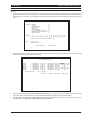
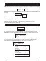
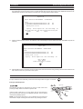
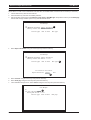
Thumbnail Search
If the GoTo key if pressed twice it will open the thumbnail search page. The thumbnail search page can be used to
search for video over a 6 hour period.
Select a thumbnail with the arrow keys and press the Enter key. This will open another thumbnail view where the time
period between thumbnails is reduced allowing you to narrow down the search. There are five stages available by
clicking a thumbnail and pressing the Enter key.
When the final thumbnail page is opened, selecting a thumbnail and pressing the Enter key will start normal playback
from that point.
SYSTEM FUNCTIONS
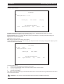
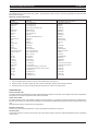
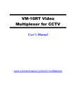
Hardware Setup Menu – Cameras (Page22)
Several changes have been made to the layout and additional features have been added.
The camera page now consists of two pages; by pressing the camera number it toggle between the two pages.
The first page is used to set up the camera parameters and actions resulting from alarm conditions.
The second page is used to set up the schedules, record rates, and files sizes which can be a different value for
alarms and motion.
There is also a global set up feature available that will force the setting of all the cameras connected on the DVR to the
setting made on this page.
SYSTEM FUNCTIONS
It is now possible to set the camera record rate to 0. This will enable the option for event / motion or alarm only
recording.
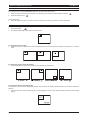
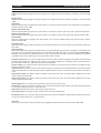
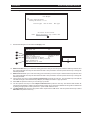
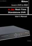
Hardware Setup Menu – Cameras (Page22)
Several changes have been made to the layout and several features have been added.
The Cameras page now consists of two pages. Pressing the camera number key will toggle between the two pages
(or select More options >>).
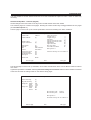
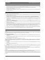
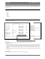
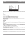
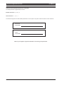
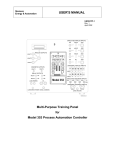
The first page is used to set up the camera parameters and actions resulting from alarm conditions.
Camera Setup - Camera 1
Camera name
Camera 1
Camera enabled
[X]
Hidden camera
Input terminated
[ ]
[X]
Dome camera
Dome ID
Bus
[X]
0001
RJ45 connector
Colour
Saturation adjust
Contrast adjust
Brightness adjust
Hue adjust
Auto-detect
100
100
100
100
Event mode
Normal
Video loss action:
Trigger relay 1
trigger realy 2
Send email
Display main monitor alert
Display spot monitor alert
Sound buzzer
Light alarm LED
Auto-copy event
Pre video loss buffer
[ ]
[ ]
[ ]
[X]
[ ]
[X]
[X]
[X]
10
More options >>
Previous page
Use these settings for all cameras >>
Exit
Next page
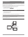
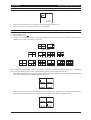
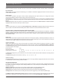
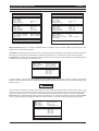
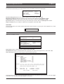
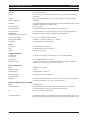
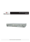
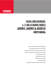
The second page is used to set up schedules, record rates and files sizes which can be different values for alarms
and motion.
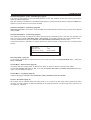
A global set up feature is available. Selecting Use these settings for all cameras will force all the cameras connected
to the DVR to inherit the settings made on the Camera setup pages.
Camera Setup - Camera 1
Camera recording
[X]
Daytime recording
Images/sec Normal
Alarm
Motion
Image size Normal
Alarm
Motion
[X]
4/50
0.100
0.100
15k
24k
24k
Min recording time:
Max recording time:
79 hours
118 hours
More options >>
Use these settings for all cameras >>
Previous page
Exit
Next page
SYSTEM FUNCTIONS
Hardware Setup Menu – Disks - Disk Manager (page 25)
This page now has options to erase individual partitions for each disk installed. Options are erase all of the disk or
erase the individual partitions.
Disk error checking is available from the Disk Manager page if you select the option ‘In use’ and press the Enter key.
Options to scan the drive for errors will be revealed.
Hardware setup Menu – Networking (page 29)
Allow Viewer Control is a new option. If it is set to NO, the Vivid DVR will reject access from any remote viewer. Default
setting is YES.
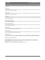
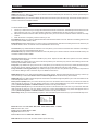
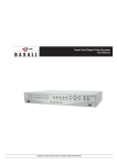
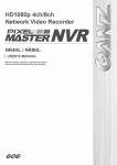
Hardware Setup Menu – Connectivity (page 29)
The RS485 and RS232 port settings have been removed from the Networking menu. They are now accessed from
their own menu by selecting Hardware setup > Connectivity. Functionality is identical to previous software builds.
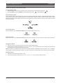
There are additional dome protocols (Santec, JVC, VCL Panasonic and Bosch) within this menu.
In the RS232 option it is possinble to configure the DVR for either text input or serial control from a Pyramid matrix
system.
RS485 usage
RS485 address
RS485 baud rate
Dome protocol (Screw)
Baxnet keyboard
9
19200
Baxall Prodome
RS232 usage
Pyramid keyboard
Recording Setup – (page 34)
On The Vivid+ unit the option to set the DVR into Turbo mode is accessed via the Record Mode option – select from
Turbo or Standard.
General Menu – Date and Time (page 39)
To facilitate DST time setting (which is different from BST) an option for all time zones has been added.
Set the Auto summer time option to Yes, then enter the summer time start and summer time end period for the
region you are installing the DVR in.
General Menu – Languages (page 39)
Additional languages available include Lithuanian, Czech, Slovakian, Polish and Turkish
General – Quick Start (page 41)
When Quick start is activated either from initial power up or via menus the first option that is presented is Select
language. This will configure the DVR automatically for the language selected. The quick start menu options for set
no of days etc, will follow.
Issue 2 01/06
HB-VIVID-AD-2
Baxall Vivid Digital Video Recorder
User Manual
Please read this manual before using the Baxall Vivid DVR
Baxall Vivid Digital Video Recorder
User Manual
IMPORTANT
The first few pages of these instructions contain important information on safety and product conformity. Please read, and ensure
that you understand this information before continuing.
TO PREVENT FIRE OR SHOCK HAZARD, DO NOT EXPOSE THIS
APPLIANCE TO RAIN OR MOISTURE
2
User Manual
Baxall Vivid Digital Video Recorder
CONTENTS
Product Safety ............................................................................................................................................................... 5
Safety Symbols ......................................................................................................................................................... 5
Important Safety Notices ........................................................................................................................................... 5
Regulatory Notices .................................................................................................................................................... 6
Unpacking ...................................................................................................................................................................... 6
Introduction .................................................................................................................................................................... 7
Overview .................................................................................................................................................................... 7
Versions ..................................................................................................................................................................... 8
System Layout ........................................................................................................................................................... 9
Front Panel Layout .................................................................................................................................................. 10
Rear Panel Layout ................................................................................................................................................... 11
Installation .................................................................................................................................................................... 12
Installation - step 1 choose a suitable location ....................................................................................................... 12
Installation - Step 2 Install DVR in Final Location ................................................................................................... 13
Installation - Step 3 Connect up DVR ...................................................................................................................... 14
Manually Set up Network Connection (Optional) .................................................................................................... 15
Configure Individual Cameras (Optional) ................................................................................................................ 15
Basic System Set up and Operation ............................................................................................................................ 16
Menu Access and Navigation .................................................................................................................................. 16
Select Operating Language .................................................................................................................................... 17
Select Date and Time Format ................................................................................................................................. 17
Set Current Date and Time ...................................................................................................................................... 17
Basic Functions ........................................................................................................................................................... 18
Selecting a Camera ................................................................................................................................................. 18
Digitally zooming a camera ..................................................................................................................................... 18
Selecting a monitor ................................................................................................................................................. 18
Playback .................................................................................................................................................................. 18
Live View ................................................................................................................................................................. 18
Reverse Playback ................................................................................................................................................... 18
Fast forward ............................................................................................................................................................. 18
Pause Playback ....................................................................................................................................................... 18
Go To ....................................................................................................................................................................... 18
Event ....................................................................................................................................................................... 19
Sequences .............................................................................................................................................................. 20
Picture in picture ...................................................................................................................................................... 20
Multiscreen .............................................................................................................................................................. 21
Telemetry ................................................................................................................................................................. 22
System Functions ........................................................................................................................................................ 23
Hardware Setup Menu ............................................................................................................................................ 23
Cameras .................................................................................................................................................................. 23
Disks ........................................................................................................................................................................ 26
Relays ..................................................................................................................................................................... 28
Alarms ..................................................................................................................................................................... 28
Networking .............................................................................................................................................................. 30
Configure Display ........................................................................................................................................................ 32
Alarm Status ................................................................................................................................................................. 34
Recording Setup .......................................................................................................................................................... 35
Replay .......................................................................................................................................................................... 38
General ........................................................................................................................................................................ 40
3
Baxall Vivid Digital Video Recorder
User Manual
CONTENTS
Appendix 1 - Main I/O Connector Pin Out .................................................................................................................... 43
Appendix 2 - Baxnet Keyboard connections ................................................................................................................ 44
Appendix 3 - Baxnet Keyboard and Dome Camera connections ................................................................................ 45
Appendix 4 - ZKX.. Keyboard Mapping ........................................................................................................................ 46
Appendix 5 - USB Keyboard Mapping ......................................................................................................................... 47
Appendix 6 - Exporting files to CD and DVD ............................................................................................................... 48
Appendix 7 - Exporting files to a USB Memory stick ................................................................................................... 50
Appendix 8 – System Specification .............................................................................................................................. 52
Appendix 9 - Passwords .............................................................................................................................................. 54
4
User Manual
Baxall Vivid Digital Video Recorder
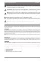
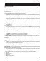
SAFETY SYMBOLS
The following symbols are used in this manual:
An exclamation mark within a triangle, indicates an important installation, operating or maintenance (service)
instruction. Failure to read and adhere to these instructions may:
•
Be potentially hazardous or operationally risky
•
Result in equipment failure or incorrect operation
•
Possibly invalidate the manufacturers warranty
A lightning flash, within a triangle, indicates that there are un-insulated “dangerous voltages” present that may
be of sufficient magnitude to constitute a risk of electric shock.
The recycling symbol, indicates that an item may need proper disposal or recycling in accordance with applicable
local government, state or federal laws.
IMPORTANT SAFETY NOTICES
Attention: The Vivid DVR is a professional piece of equipment that is designed for use within a commercial environment
for general security and surveillance applications. Installation and service should be performed by suitably qualified
personnel only in accordance with local government, state or federal laws.
Power disconnect: The Vivid DVR has no “on/off” switch. Power is disconnected by switching off the supply to the
Vivid DVR’s external power supply unit (PSU) at the mains electrical supply socket and removing the DC power cord
from the back of the Vivid. For this reason, the mains electrical supply socket should be close to, and easily accessible
from the Vivid DVR.
Warning: To reduce the risk of fire or shock, do not expose the Vivid DVR or its PSU to rain or moisture.
Vivid DVR instructions: Read and comply with all the safety, installation and operating instructions for the Vivid
DVR when installing and operating your new system.
Keep all the safety, installation and operating instructions supplied with the Vivid DVR for future reference.
If you are unsure about any aspect of the instructions supplied with the Vivid DVR, please contact your local Baxall
distributor, dealer or installer before proceeding to install, set-up or use the system.
Other equipment instructions: The Vivid DVR cannot be installed and operated without being connected to other
equipment within a complete CCTV system, such as cameras and monitors. Read and comply with all the safety,
installation and operating instructions for the equipment you intend to connect your Vivid DVR to when installing and
operating your system.
If you are unsure about any aspect of the instructions supplied with the equipment you intend to connect to your Vivid
DVR, please contact your supplier.
Ventilation: To avoid the risk of overheating and a reduction in the operating life of the Vivid DVR, ensure that no
ventilation openings in the system are blocked and that the installation instructions contained in this document are
adhered to.
Do not install the Vivid DVR near any heat sources such as radiators or hot air ducts.
Lifting and handling: The Vivid DVR is heavy and may cause injury if incorrectly lifted or handled. Always follow
your local Health and Safety or OSHA guidelines when lifting the Vivid DVR from its package or installing the unit.
Rough handling: The Vivid DVR contains hard disk drives. These are sensitive to shock and easily damaged –
especially when the system is powered up. Rough handling or sharp shocks to the system, whether during installation
or during system use, may damage the hard disk drives and possibly invalidate the system warranty.
Electrostatic-sensitive device: During installation, and especially if working inside the Vivid DVR’s chassis, always
use proper antistatic precautions, including correctly fitted wrist straps, to avoid damage to the Vivid DVR or its
internal electronics from unintentional electrostatic discharge.
5
Baxall Vivid Digital Video Recorder
User Manual
IMPORTANT SAFETY NOTICES
Fast Transients and Surge: regardless of the inbuilt protections of the Vivid DVR, Baxall Ltd recommend that
appropriate fast transient and surge protection is fitted to all vulnerable cables, such as video and Ethernet cables
and that other cables, such as s-video cables, SCSI cables, etc., are kept to lengths of less than 3m to minimise risk
of damage to the Vivid DVR or loss of valuable video data.
All installations: Baxall Ltd strongly recommend that for all installations – especially those that may be security
critical, or that are in areas subject to surges, dips, or interruptions in the mains electrical power supply – that a
suitable uninterruptible power supply (UPS) is used to condition and protect the Vivid DVR and its peripherals.
Warning: The primary purpose of this product is to digitise, compress, record and playback CCTV video. The other
secondary features of this product, such as motion detection, alarm handling and audio recording, are provided for
convenience and should not be relied upon as the primary means of meeting requirements for these functions in an
installation.
Lithium battery: The Vivid DVR contains a replaceable lithium battery. This battery must only be replaced by a
suitably qualified service engineer with the same type as originally fitted to the system.
After removal the original battery must be disposed of or recycled in accordance with local government, state or
federal laws.
Warning: Risk of explosion. Do not incinerate the replaceable lithium battery in the Vivid DVR.
REGULATORY NOTICES
FCC (USA Only)
This device complies with part 15 of the FCC Rules. Operation is subject to the following two conditions: (1) This device may
not cause harmful interference, and (2) this device must accept any interference received, including interference that may
cause undesired operation.
This equipment has been tested and found to comply with the limits for a Class A digital device, pursuant to part 15 of the
FCC Rules. These limits are designed to provide reasonable protection against harmful interference when the equipment is
operated in a commercial environment. This equipment generates, uses, and can radiate radio frequency energy and, if not
installed and used in accordance with the instruction manual, may cause harmful interference to radio communications. Operation
of this equipment in a residential area is likely to cause harmful interference in which case the user will be required to correct
the interference at their own expense.
Modifications not expressly approved by the manufacturer could void the user’s authority to operate the equipment under FCC
rules.
CE Mark (EU Only)
The manufacturer declares that the product supplied is compliant with the provisions of the EMC Directive 89/336 EEC, the
Low Voltage Directive 72/23 EEC and the CE marking directive 93/68 EEC and associated amendments. A “Declaration of
Conformity” in accordance with the above directives is held on file at Baxall Limited, Stockport SK6 2SU, England. A copy of
which is available upon request.
This is a Class A product. In a domestic environment this product may cause radio interference, in which case the user may be
required to take adequate measures.
UNPACKING
Check you have the following items included in the Vivid DVR package:
•
Vivid DVR
•
External power supply unit, with integral 12V power cord
•
IEC electrical mains power cord
•
2 rack mounting brackets
•
Vivid DVR User manual
•
Vivid DVR PC Remote Viewing Software (on CD-ROM)
6
User Manual
Baxall Vivid Digital Video Recorder
INTRODUCTION
Welcome to the Vivid DVR User manual. This manual contains all the information you need to install, set up and operate your
Vivid DVR.
Read and Retain Safety Notices
Read and retain for future reference the Vivid DVR Safety Notices above. If you are unsure about the meaning of the Safety
Notices or any other aspect of the Vivid DVR User manual, please contact your local distributor, dealer installer or Baxall Ltd for
guidance before proceeding to install, set-up or use the Vivid DVR.
Gather Equipment and Tools
Ensure you have all the other equipment and tools you require for your Vivid DVR installation. For a minimum installation, you
will require:
•
At least one PAL or NTSC CCTV surveillance camera and power supply.
•
At least one (main) CCTV surveillance monitor and power cord, compatible with the PAL or NTSC surveillance camera
above.
•
Suitable coaxial cables to connect the camera to the Vivid DVR and either a coaxial or S-Video cable to connect the Vivid
DVR to the monitor.
•
A standard Ethernet cable if the system is to be connected to a network.
Ensure you are familiar with all of the safety and installation requirements of the other equipment you plan to install with your
Vivid DVR before proceeding with the installation process.
Note: Other equipment, typically a TV monitor, may be supported on top of the Vivid DVR – provided the weight of the other
equipment does not exceed 16Kg (35 pounds), the ventilation holes and fans in the side of the Vivid DVR are not obstructed,
and the equipment placed on top of the system is not outside the operating temperature range of the Vivid DVR.
OVERVIEW
The Vivid DVR is a purpose made embedded digital video recorder designed for closed circuit television (CCTV) security and
surveillance applications.
The Vivid DVR combines into a 1½U single 19" rack sized unit the functionality of a:
•
Video multiplexer,
•
Digital video recorder,
•
Network video server.
Key features of all Vivid DVRs include:
•
Powerful embedded 32bit RISC for purpose made performance and functionality.
•
JPEG2000 image compression for high quality picture recording and advanced image compression features.
•
Up to two internal ATA hard disk drives and SCSI-2 i/o for market leading video storage capability.
•
USB 2 for convenient connectivity to standard PC USB keyboards, USB CD-RW or DVD-RW devices and USB memory
sticks.
•
Front key pad (or external USB keyboard or remote keyboard) control of market leading domes for low cost PTZ integration.
•
Fast (100bT) Ethernet with TCP/IP support, network viewing software and SNMP network management for advanced
network video replay, integration and management capabilities.
•
Linux operating system for reliable 24/7 operation and the ability to support 3rd party developed value-added applications.
In addition, all Vivid DVRs feature a comprehensive CCTV specification, including:
•
Motion detection.
•
16 alarm inputs and 2 relay outputs.
•
Protected event recording and logs.
•
E-mail event alerts.
•
RS232 text recording.
•
Single channel audio recording.
•
Remote (PC) viewing software (with suitable PC).
•
BaxNet remote keyboard support.
7
Baxall Vivid Digital Video Recorder
User Manual
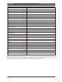
VERSIONS
Features
VIVID Lite
VIVID
VIVID+
Record speed
25pps
50pps
50pps + TURBO*
Mode
Duplex
Triplex
Triplex
Internal Writer
CD
No
DVD
Alarms
Yes
Yes
Yes
SVHS Monitor
No
Yes
Yes
Audio
No
Yes
Yes
SCSII
No
Yes
Yes
Front panel USB
Yes
Yes
Yes
BaxNet
Yes
Yes
Yes
Dome Control
Yes
Yes
Yes
Ethernet
Yes
Yes
Yes
*In TURBO mode the VIVID+ unit will record at a rate of 100pps at half image resolution
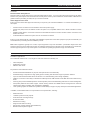
Product codes
VIVIDLite 6/80
DVR, Duplex, CD, 6 channel, 80Gb hard drive
VIVIDLite 6/320
DVR, Duplex, CD, 6 channel, 320Gb hard drive
VIVIDLite 10/160
DVR, Duplex, CD, 10 channel, 160Gb hard drive
VIVIDLite 10/320
DVR, Duplex, CD, 10 channel, 320Gb hard drive
VIVIDLite 16/160
DVR, Duplex, CD, 16 channel, 160Gb hard drive
VIVIDLite 16/320
DVR, Duplex, CD, 16 channel, 320Gb hard drive
VIVIDLite 16/600
DVR, Duplex, CD, 16 channel, 600Gb hard drive
VIVID 6/80
DVR, Triplex, 6 channel, 80Gb hard drive
VIVID 6/320
DVR, Triplex, 6 channel, 320Gb hard drive
VIVID 10/160
DVR, Triplex, 10 channel, 160Gb hard drive
VIVID 10/320
DVR, Triplex, 10 channel, 320Gb hard drive
VIVID 10/500
DVR, Triplex, 10 channel, 50Gb hard drive
VIVID 16/160
DVR, Triplex, 16 channel, 160Gb hard drive
VIVID 16/320
DVR, Triplex, 16 channel, 320Gb hard drive
VIVID 16/600
DVR, Triplex, 16 channel, 600Gb hard drive
VIVID 16/1000
DVR, Triplex, 16 channel, 1Tb hard drive
VIVID+ 6/80
DVR, Triplex, DVD, 6 channel, 80Gb hard drive
VIVID+ 6/320
DVR, Triplex, DVD, 6 channel, 320Gb hard drive
VIVID+ 10/160
DVR, Triplex, DVD, 10 channel, 160Gb hard drive
VIVID+ 10/320
DVR, Triplex, DVD, 10 channel, 320Gb hard drive
VIVID+ 10/500
DVR, Triplex, DVD, 10 channel, 500Gb hard drive
VIVID+ 16/160
DVR, Triplex, DVD, 16 channel, 160Gb hard drive
VIVID+ 16/320
DVR, Triplex, DVD, 16 channel, 320Gb hard drive
VIVID+ 16/600
DVR, Triplex, DVD, 16 channel, 600Gb hard drive
VIVID+ 16/1000
DVR, Triplex, DVD, 16 channel, 1Tb hard drive
8
User Manual
Baxall Vivid Digital Video Recorder
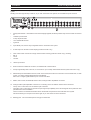
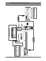
SYSTEM LAYOUT
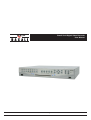
The Vivid DVR consists of a 1 1/2 U 19 inch rack mount unit that is 44cm (17 inches) wide and 37cm (14 inches) deep that
weighs approximately 5Kg (11 pounds) with a single disk drive fitted. The system has a robust all-metal enclosure with a plastic
moulded front panel which contains a rubber membrane key pad and a USB 2 port – all other I/O and power ports are located
on the rear panel of the unit. The sides of the Vivid DVR feature rack ear mounting points on both sides, ventilation input vents
on the right and fan exhaust vents on the left:
Figure 1 Front Left View Vivid DVR
Optional rack ears are supplied with the unit for rack-mounted installations, and stick on rubber feet are supplied for desktop
applications.
9
Baxall Vivid Digital Video Recorder
User Manual
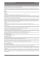
FRONT PANEL LAYOUT
The function of these keys is straightforward:
Camera / Zoom / Setup Keys
The camera/zoom/setup keys allow you to:
•
Select which camera is displayed on the monitor,
•
Digitally zoom a specific camera view, by double pressing the relevant camera key.
•
Enter the setup menu for a specific camera, by pressing and holding the relevant camera key.
The camera keys are also used to enter numbers in the menu system and to set and activate PTZ presets, when the Vivid DVR
is in PTZ control mode.
Video Playback Keys
The video playback keys allow you to control the replay of recorded video:
•
The GO TO key calls up a date and time entry screen, which allows you to go to a specified date and time and replay any
video recorded.
•
The EVENT key calls up a list of saved system, motion detection or alarm events (depending on the setup of the unit),
which can then be selected and replayed,
•
The Play, Rewind, Fast forward and Pause keys, which function like the keys on a VCR. In particular, the play and
rewind and fast forward keys allow you to instantly replay recorded video for whichever camera is currently viewed or
selected.
•
The STOP/LIVE button, which stops the replay of recorded video and returns the display to live video.
The GO TO and ENTER keys also double up as the zoom in and zoom out keys, when the Vivid DVR is in PTZ control.
Navigation Keys
The navigation keys consist of:
•
Four arrow keys, which are used for navigate between camera windows in multi-screen mode and for navigating through
the Vivid DVR menu.
When navigating menus:
•
The up and down arrow keys are used for moving up and down menu lists to highlight the required item, and also for
increasing or decreasing values in text and number input boxes.
•
The left and right arrow keys are used for moving up and down between menu levels, and also, in the case of the right
arrow key, for selecting highlighted menu options.
The arrow keys also provide tilt up, tilt down, pan left, pan right functions, when the Vivid DVR is in PTZ control mode.
•
The ENTER key, which is used to select menu options from drop down lists, or to confirm numbers or text entered with the
arrow keys. The ENTER key is also used to select the active camera in multi-screen mode, or, when followed by a press
of the MON A/B key, to activate telemetry and control selected PTZ cameras.
•
The MENU key, which is used to enter or leave the Vivid DVR menu system.
The ENTER and MENU keys also double up as the focus near, focus far keys, when the Vivid DVR is in PTZ control mode.
Display Keys
The display keys, which control the selection and display of cameras on the monitors and consist of:
•
The MON A/B, which switches the active display between the MAIN and the SPOT monitor.
This key is also used in combination with the ENTER key – see above – to activate PTZ control mode on a selected, active
camera
•
The PIP key, which activates a picture in picture display, and also changes the size of the PIP window. Repeat pressing
also changes the position of the PIP display on the monitor.
•
The SEQ key, which activates the display to sequence between all the cameras enabled on the system.
•
The MULTI key, which toggles the display through the various multiscreen displays offered by the Vivid DVR.
Other Front Panel Features
Health Check LEDs – The front panel features four LEDs, located below the video playback keys. These LEDs provide a quick
overview of the health of your Vivid DVR. They consist of:
•
Three blue LEDS, which, from left to right, indicate that the system is correctly powered, recording video, and connected
to a working network.
•
One blue LED, which is lit whenever an alarm event is detected or a system malfunction condition exists.
USB 2.0 Port – Mounted in the lower right hand side of the front panel, below the “display” keys, the Vivid DVR features a
convenient ‘plug & play’ USB 2.0 port, which can be used for connecting a variety of useful devices, including:
•
CD rewriters
•
USB memory sticks
•
PC keyboards
•
DVD-Rom writers/re-writers
10
User Manual
Baxall Vivid Digital Video Recorder
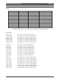
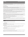
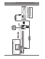
REAR PANEL LAYOUT
The back panel of the Vivid DVR provides a wide variety of input and output (I/O) ports to enable you to make the most of your
system.
Working from left to right and top to bottom, as you look at the back of the system, the Vivid DVR I/O ports consist of:
1.
26-way terminal block. Used with the screw terminal plugs supplied, this block provides easy and convenient connections
for:
•
16 alarm input terminals
•
4 relay output terminals
•
1 two-wire RS485 terminal
•
4 grounds
2.
9-pin RS232 port, which is fully configurable from the Vivid DVR menu system.
3.
S-Video output for the main monitor display (VIVID and VIVID+ only)
4.
Three 3.5mm audio connectors for single channel audio recording (VIVID and VIVID+ only), including:
•
MIC In
•
Line In
•
Line Out
5.
12VDC input socket.
6.
RJ45 10/100 base T Ethernet connector, for Fast Ethernet communications.
7.
A 50 pin high density SCSI connector, for connection to up to 3 daisy-chained RAID devices (VIVID and VIVID+ only).
8.
Stacked dual port RJ45 RS485 connector, which can be used, like the two wire connection on the terminal block, for PTZ
control, or for daisy-chaining RS485 devices using Baxnet.
Note: This is a single logical RS485 I/O port on to the Vivid DVR.
9.
MON A, main monitor, and MON B, SPOT monitor, analogue video output BNC connectors.
10. Analogue video input/output BNC connectors for connecting CCTV surveillance cameras to the Vivid DVR:
•
The top row of connectors is for the camera input connection.
•
The bottom row of connectors is to provide a loop-through output capability so the camera signals can be passed to other
possible devices in the installation.
These connectors are software terminated and un-terminated as required from the Vivid DVR menu system.
Camera numbering is in sequence from left to right, as you look at the rear of the Vivid DVR.
11. Earthing point. Use of this Earth point is strongly recommended.
11
Baxall Vivid Digital Video Recorder
User Manual
INSTALLATION - STEP 1 CHOOSE A SUITABLE LOCATION
Introduction
The Vivid DVR design is robust, has a wide temperature and humidity operating range, and has been independently tested to
comply with the demanding system immunity requirements (ESD, Fast Transients, Surge and Radiated Immunity) of the
European standard for Electronic Security Systems, EN50130-4.
Nevertheless, locating the Vivid DVR in a controlled or benign environment, such as in an equipment rack in a server room
(ideally) or an air-conditioned office, and paying careful attention to the following issues will minimise the possibility of in-use
equipment failures – with the possible consequent loss of important data - and maximise the operating life of your new Vivid
DVR.
Moisture
To avoid shock hazards or the risk of fire ensure that the Vivid DVR is not installed anywhere that it will be exposed to rain or
moisture.
Temperature
The Vivid DVR has a specified operating temperature range of 0°C to 40°C (32°F to 104°F).
However, like all computer equipment, an ambient temperature range of 21°C to 23°C (70°F to 74°F) is optimal for long-term
system reliability. A temperature level near 22°C (72°F) is also desirable because it makes it easier to maintain a safe relative
humidity level (see below). This recommended temperature also provides an operational buffer in case the environmental
support systems, such as air conditioning, malfunction.
Note: The operating temperature range for the Vivid DVR applies to the air taken in by each Vivid DVR at the point where the
air enters the system – and not necessarily the ambient temperature in the room where the system is installed. To check the
temperature of the air entering the Vivid, measure the temperature at 5cm (2 inches) from the right side of the equipment.
Caution: For maximum reliability please ensure that the Vivid DVR is not placed next to a source of excessive heat, such as
a radiator, hot equipment, or hot air duct or exhaust vent.
Humidity
The Vivid DVR has a specified operating range of 20% to 90%, non-condensing, relative humidity (RH).
However, like all computer equipment, an ambient relative humidity level between 45% and 50% is most suitable for long term
system reliability.
The main reason for this is that the amount of moisture that air can hold is temperature dependent. Therefore, if the relative
humidity is at either extreme of the safe operating range of the equipment, relatively small changes in ambient temperature can
easily result in the relative humidity moving outside the operating limits of the system.
In the case of very high relative humidity, a small reduction in temperature may lead to moisture condensing on the system –
possibly causing long term system damage through corrosion.
At the other extreme, low temperatures and low relative humidity, a small temperature increase may result in an unacceptably
low relative humidity leading to a greatly increased risk of intermittent interference, and even possible system damage, from
electrostatic discharge (ESD). This is especially true for relative humidity levels below 35%.
Operating the equipment in a relative humidity range of 45% to 50% minimises the risk of the above problems and ensures the
widest margin of time to fix a problem in the event of an environmental system failure.
Environmental Stability
For maximum long-term system reliability, environmental conditions should not be allowed to change by more that 5.5°C (10°F)
or 10% relative humidity in an hour.
Ventilation and Cooling
The Vivid DVR draws in ambient air for cooling from the right and discharges heated exhaust air to the left of the system (when
looked at from the front). Ensure that the air vents on either side of the system are not obstructed. In particular, ensure that
there are no obstructions within 5cm (2 inches) of either side of the system.
When installing the Vivid DVR in an equipment rack within a server room, take care to ensure that the heat output of the Vivid
DVR (listed in the specifications section at the back of this manual) is taken fully into account when calculating the cooling
requirements of the server room and that there is an adequate flow of cooled air to the system.
Note: In all installations, ensure that the cool air intake vents on the right side of the system are not close to the hot air exhaust
vents of any other system.
Environmental Acclimatisation
Prior to installing and powering up the Vivid DVR you should compare the temperature and humidity of the environment in
which the system had been stored to the conditions in the location where the unit is to be eventually installed.
Electronic equipment can be damaged if the rate of temperature or humidity change that it is exposed to is too great - especially
when power is applied to the system. The maximum positive or negative temperature gradient that is recommended for
multilayered printed circuit boards is approximately 2°C (4°F) per hour. The same applies to humidity; it is best for change to
occur slowly.
Therefore, if it is necessary to compensate for significant temperature or humidity differences between the system and the
installation location, place the Vivid DVR, in its shipping packaging, in a location that has a similar temperature and humidity
environment as the eventual location for at least 24 hours before installation to prevent possible damage from thermal shock
and condensation.
12
User Manual
Baxall Vivid Digital Video Recorder
INSTALLATION - STEP 1 CHOOSE A SUITABLE LOCATION
Vibration and Shock
The Vivid DVR contains up to two internal hard disk drives. These disk drives are susceptible to damage from excessive shock
and vibration – especially when powered up and in use.
Ensure that the chosen location for the Vivid DVR protects the system from accidental shocks and vibration whilst in use.
Also, ensure the system is properly powered down, and not subjected to rough handling, before any installation, maintenance
or removal activity.
Electrical Power Supply
The effects of power disturbances on sensitive electronic equipment can include data errors, system halts, memory or program
loss, or equipment damage. Further, electronic equipment that is subject to repeated power interruptions or fluctuations can
experience a higher component failure rate than equipment that has a stable power source.
For security critical installations, the power infrastructure should be properly designed – through the use of UPS, backup
generators, and secondary power feeds - to maintain system up time even during disruption of the main power source.
In all installations, using an online uninterruptible power supply (UPS) is a good strategy for obtaining a clean, stable power
source. The online UPS filters, conditions, and regulates the power. It protects the systems from fluctuating voltages, surges
and spikes, and noise that may be on the power line.
The battery backup for the UPS should be capable of maintaining the critical load of the Vivid DVR for a minimum of 30 minutes
during a power failure. After which time, depending on the type of UPS selected, the Vivid DVR can be automatically powered
down in a controlled fashion to protect both the system hardware and the data captured on the hard disks.
In a security critical installation that has been properly constructed, 30 minutes should typically provide sufficient time to allow
for the transfer of power to an alternate feed or to the backup power generator.
Grounding
A properly installed Vivid DVR is grounded through the power cable. However, additional grounding, using the designated Earth
point on the rear of the chassis helps to protect the system from potential immunity problems, such as ESD and high energy
radiated RF fields. Baxall Ltd recommends the use of this additional grounding facility in all Vivid DVR installations.
Grounding design in the United States should comply with U.S. National Electrical Code unless superseded by local codes. For
international operation, consult the country or local electrical codes.
In all cases, enlist the aid of a qualified electrician to install grounding cables.
Qualified service personnel should always use an antistatic wrist strap when working inside the Vivid DVR chassis.
Physical Security and Fire Protection
Video footage captured by the Vivid DVR may be important evidence. Give consideration when locating the Vivid DVR to its
physical protection from unauthorised access and from fire risks. The ideal location for your Vivid DVR is a controlled server
room location.
INSTALLATION - STEP 2 INSTALL DVR IN FINAL LOCATION
Introduction
The Vivid DVR is designed to be used in two basic kinds of location:
1.
Rack-mounted in a standard 19 inch electronic equipment rack
2.
As a desktop unit.
Lifting and Handling
The Vivid DVR is heavy and may cause injury if incorrectly lifted or handled. Always follow your local Health and Safety or
OSHA guidelines when lifting the Vivid DVR from its package.
Desktop Location
No special precautions or instructions are required for locating the Vivid DVR on to a desktop location – other than to:
•
Install the rubber feet (supplied) on to the base of the Vivid DVR to insulate the unit from vibrations and shock
•
Observe proper lifting precautions commensurate with the weight and size of the system.
Rack-mount Location
When rack-mounting a Vivid DVR please follow the following instructions:
•
Fit the rack ears (supplied) to the front sides of the Vivid DVR.
Caution: All four rack ear mounting points must be used to attach the rack ears to the Vivid DVR and the connecting screws
used to mount the rack ears must be fully tightened into the body of the system.
Warning: Failure to follow this instruction properly may result in possible injury to personnel or damage to the Vivid DVR
13
Baxall Vivid Digital Video Recorder
User Manual
INSTALLATION - STEP 2 INSTALL DVR IN FINAL LOCATION
•
Consult the appropriate rack-mounting documentation for the rack cabinet being used before attempting to install any
Vivid DVR into a rack,
•
Before attempting to install a Vivid into a rack make sure the rack is stable by either fully extending its anti-tip legs (if
mounting the Vivid on a slide-out shelf) or ensuring the rack cabinet is firmly located or attached to the floor,
•
Baxall recommend that in all cases the rear or sides of a rack-mounted Vivid DVR should be supported by suitable rack
shelves or supports in addition to the main rack ears at the front of the unit
•
In a mixed installation, install the heaviest installation items, such as RAID devices or UPS, in the lowest possible positions
in the rack
•
If installing additional Vivid DVRs, install the remaining systems from the lowest system upward into the rack.
Note: Baxall Ltd always recommends that a ½U vertical gap is left between rack-mounted equipment.
INSTALLATION - STEP 3 CONNECT UP DVR
Connect Cameras
Connect a coaxial cable to the video output BNC connector of the CCTV camera. Connect the other end of the coaxial cable
to the top row camera 1 video input BNC connector on the Vivid DVR. The lower connector is a loop-through connector for
connecting the video signal from the camera through to other equipment.
Depending on the model of Vivid DVR ordered, up to 6, 10 or 16 CCTV cameras can be connected to a single Vivid DVR.
Connect Main Monitor
Connect the Vivid DVR to the main monitor. This can be achieved by either using an S-Video cable to connect the Vivid DVR
to the S-Video input on the monitor, or by using a coaxial cable to connect the MON A video output BNC connector on the Vivid
to a video input BNC connector on the monitor.
The MON B video output connector is used for connecting a second SPOT monitor to the Vivid DVR, if required.
Connect Cameras and Main Monitor to Power Supply
Connect the CCTV cameras and main monitor to the power supply, in accordance with the manufacturers instructions.
Ensure the CCTV cameras and main monitor are powered up before powering up the Vivid DVR.
Connect to Network
Connect one end of the Ethernet cable into the Ethernet port on the Vivid DVR and the other into a local Ethernet network port.
Note: Contact your IT/IS department for advice on which external network port to use and also to ask if the local network will
provide an IP address automatically, using DHCP, or whether the IP address of the Vivid needs to be configured manually? In
the latter case, ask them to provide you with details of all the IP addresses you will need later on in the installation process.
Make a note of the numbers they provide you with here:
•
Mandatory information for manual network set up:
•
Optional information for manual network set up:
Connect DVR to Power Supply
Plug the Vivid DVR external power supply into the 12 Volts socket on the back of the unit. Connect the power cord supplied into
the external power supply and plug the power cord into your mains power source or UPS (recommended).
The Vivid DVR will now commence its power up and self-test routines:
•
On power up, the Vivid DVR will momentarily sound its alarm buzzer.
•
The fans and disk drives will power up and the green power LED on the front panel will light up.
•
After about one minute the monitor screen will momentarily display the Vivid DVR welcome screen and, if a camera is
connected to the camera 1 video input BNC, the Vivid DVR will then display a full screen live image from camera 1.
•
Finally, the blue recording LED on the front panel will light up, to confirm the unit is recording. Also, if DHCP is in use, the
blue network LED on the front panel will light up to indicate that the Vivid is connected to the local network.
14
User Manual
Baxall Vivid Digital Video Recorder
INSTALLATION COMPLETE
At this point, the Vivid DVR will be in the following default configuration:
•
All cameras detected at power up will be enabled, viewable and recording at a default rate picture rate and recorded
image size dependant on the the Quick Start menu settings, and an image file size per camera of 24KB,
•
Camera 1 will be displayed on the main monitor.
•
The system will be available for viewing over the network using the Vivid DVR remote Viewer software supplied
separately with the unit.
MANUALLY SET UP NETWORK CONNECTION (OPTIONAL)
This step only applies if DHCP is not being used and the Vivid DVR network connection needs to be configured manually.
Otherwise, skip to Configure Individual Cameras.
1.
Press the menu key to re-enter the Vivid menu system. The Hardware setup option will be highlighted and this should be
selected by pressing the enter key.
2. Navigate down to the networking option using the down arrow key, then select the highlighted Networking option by
pressing the enter key (note that the Ethetnet option needs to be enabled before the following options are visible).
3. Navigate down to the Use DHCP option using the down arrow key and, once it is highlighted, select this option using the
right arrow key. A drop down list will be displayed, use the arrow keys to select the No option and press enter (No is the
default setting).
4. Navigate down the Networking menu display using the down arrow key until the IP addresses option is highlighted, press
the right arrow key to select this option.
5. Using the information you previously recorded in section 3, use the arrow keys to navigate to and select each IP address
that needs to be set in turn.
6. When the address you want to enter is highlighted press the right arrow key. This brings up the input box for each address.
7. Use the right arrow to move along the address and the up and down arrow keys to increase or decrease the numbers until
the correct address is displayed. Alternatively, the camera number keys (1 to 9) can be used to enter numbers.
8. When you have correctly entered an address press the enter key to confirm it. This will close the address input box.
9. Use the up and down arrow keys to highlight the next address and so on until all the required addresses are correctly input.
10. When all the addresses are complete press the menu key to exit the Vivid DVR menu system.
CONFIGURE INDIVIDUAL CAMERAS (OPTIONAL)
If required you can alter the picture size (quality) and record rate for each individual camera you have connected to the Vivid
DVR.
The easiest way to do this is to press and hold the camera key of the camera you want to configure. After entering the
password, this will take you to the camera recording menu for the camera concerned.
Picture Size (Image Quality)
1. To set the picture size, press the down arrow until the picture size option is highlighted and press the enter key to enter
edit mode.
2.
Use the up/down arrow keys to either increase the file size (improve recorded picture quality) or reduce the file size
(decrease the recorded picture quality).
3.
Press the enter key once you have selected the file size required.
Note: Larger image file sizes take up more hard disk space, so your system will record better pictures but for less elapsed time.
Smaller image sizes take up less hard disk space, so your system will record reduced quality pictures but for a longer time.
Recording Rate
1. To set the record rate, after you have set the image file size, use the arrow keys to highlight Normal pics/sec for Daytime
recording.
2.
Once highlighted, press the enter key.
3.
Press the up/down arrow keys to increase or decrease the record rate and press the enter key when the correct rate is
selected.
Notes: A higher record rate generates more pictures to save to hard disk. Therefore, a higher record rate will provide pictures
at more frequent intervals but reduce the elapsed time for which the system can record.
The Vivid DVR is a multiplexed system. In other words its total maximum record rate of 50pps (PAL) and 60pp (NTSC) for a
720x240 image have to be shared between the various cameras on the system.
Finally
When you have finished setting the image file size and the record rate for the camera selected, select Next page. Repeat for
the next camera as required until all the cameras you wish to individually set up have been configured.
Once you have finished adjusting the image file size, the recording menu will give you an estimate, based on image size,
record rate, hard disk size and other system parameters, of the elapsed time for which your system will record with those
settings.
15
Baxall Vivid Digital Video Recorder
User Manual
CONFIGURE INDIVIDUAL CAMERAS (OPTIONAL)
Setting image file size and record rate is a practical compromise between picture quality and pictures per second versus
available hard disk space and the time for which the system can record.
Experiment with the settings of your Vivid DVR to achieve the best picture quality and recording rate for your application needs.
Press the enter key to exit the Vivid DVR menu system.
Congratulations, you have now completed the basic installation and set up of your Vivid DVR. Please take time to get familiar
with the basic operation of your new system before accessing and setting up the advanced features of your Vivid DVR. If you
need to access, more advanced system functions please see the next sections for details.
For require further detail on any aspect of your Vivid DVR please refer, in this order, to:
•
•
•
Your local Baxall Ltd distributor, dealer or installer,
The Baxall on-line support pages at www.baxall.com/vivid, or
Baxall Ltd technical support on: +44 (0)161 406 6611.
BASIC SYSTEM SET UP AND OPERATION
To complete the setup of a basic system configuration access the Vivid DVR menu system and:
•
Select the operating language of the system,
•
Choose the preferred time and data format,
•
Set the local system time and date.
If DHCP is not in use on the local network, it will also be necessary to use the IP addresses you have already obtained from
your IT/IS department and recorded in Step 3 to manually set up the Vivid DVR network access.
MENU ACCESS AND NAVIGATION
To access the menu system, press the menu button, enter the password and then navigate through the menus displayed on
the main monitor using the up, down, left and right navigation keys on the Vivid DVR.
Note: The menu system will time out after a default period of 90 seconds inactivity. This can be altered if required at a later
stage through the General menu display.
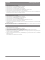
MENU HIERARCHY
Cameras
Disks
Relays
Alarms
Networking
Main monitor
Spot monitor
Hardware setup
Configure display
Alarm status
Recording setup
Replay
General
16
{
Displays current alarm status
Displays current motion detection status
Schedule
Motion detection
Sound
RS232 Data
User Manual
Baxall Vivid Digital Video Recorder
SELECT OPERATING LANGUAGE
1.
Access the Vivid DVR menu system by pressing the menu key and entering the installer password. The top-level menu
window is displayed on the main monitor.
2.
Press the down arrow key until the General option is highlighted.
3.
Press the enter key. The General menu window is displayed.
4.
Press the down arrow key until the Language option is highlighted.
5.
Press the enter key. A drop down list opens, displaying all the available language options.
6.
Press the down arrow key until the required language option is highlighted.
7.
Press enter. The required language option is selected. The drop down list is closed – the menus are now displayed in the
selected language – and you remain in the General menu window.
1.
Access the Vivid DVR menu system by pressing the menu key and entering the installer password. The top-level menu
window is displayed on the main monitor.
SELECT DATE AND TIME FORMAT
2.
Press the down arrow key until the General option is highlighted.
3.
Press the enter key. The Date and Time menu window is displayed.
4.
Press the down arrow key to highlight the Date format option.
5.
Press the enter key a drop down list appears displaying all the available date format options.
6.
Press the down arrow key until the required format is highlighted.
7.
Press enter. The required date and time format is selected. The drop down list is closed and you are returned to the Date
and Time menu window.
Note: More advanced time options, such as using an RS485, NTP or GPS time source, along with a discussion of how summer
time settings are handled by the Vivid DVR are covered later in this manual.
SET CURRENT DATE AND TIME
1.
Access the Vivid DVR menu system by pressing the menu key and entering the installer password. The top-level menu
window is displayed on the main monitor.
2.
Press the down arrow key until the General option is highlighted.
3.
Press the enter key. The Date and Time menu window is displayed.
4.
Highlight the Date and Time option. Press the right arrow key. The Date and Time input box is displayed.
5.
Press the right arrow key to move along the Date and Time input box, using the up and down arrow keys at each point to
increase or decrease the number displayed.
6.
When the correct date and time has been entered, press the enter key to implement the new date and time. The Date and
Time input box closes.
Press the menu key to exit the Vivid DVR menu system.
17
Baxall Vivid Digital Video Recorder
User Manual
BASIC FUNCTIONS
This section covers basic user functions such as selecting cameras, selecting monitors, etc. A quick reference guide is also
included with the Vivid DVR detailing common operations and functions.
SELECTING A CAMERA
To select a camera for full screen viewing:
1.
Press the camera number button corresponding to the camera you want to view.
The selected camera will be shown full screen on the main monitor.
DIGITALLY ZOOMING A CAMERA
Cameras connected to the Vivid DVR can be digitally zoomed by a factor of approximately 2:1. To digitally zoom a camera:
1.
Press the camera number button twice in quick succession for the camera you want to zoom.
2.
The arrow keys can be used to scroll the image. To return to full screen mode, press the camera number button again.
SELECTING A MONITOR
The Vivid DVR can have two monitors connected to it: a main monitor and a spot monitor. To change the active display:
1.
Press the MON A/B key to toggle the active display between the main and spot monitors.
PLAYBACK
To begin playback, press the Play key. Playback will occur at the rate it was recorded. Playback is indicated by a > after the time
display (e,g, 12:00:00>).
LIVE VIEW
To stop playback, press the Stop key. The unit will go into live view mode. Note: Pressing the Stop button stops playback only
- the unit does not stop recording.
REVERSE PLAYBACK
Press the reverse playback key once for normal speed playback. This will be indicated by a < after the time display (e,g,
12:00:00<) Press reverse play again for higher speed playback.This will be indicated by a << after the time display (e,g,
12:00:00<<). Press reverse play again for higher speed reverse playback (indicated by <<< after the time display). Press
reverse play again for high speed reverse playback (indicated by <<<< after the time display).
FAST FORWARD
Press the fast forward key once for fast forward playback. This will be indicated by > after the time display (e,g, 12:00:00>).
Press fast forward again for higher speed fast forward playback (indicated by >> after the time display). Press fast forward
again for higher speed fast forward playback (indicated by >>> after the time display). Press fast forward again for higher speed
fast forward playback (indicated by >>>> after the time display).
PAUSE PLAYBACK
To pause playback press the pause key.
Pressing the pause key again will resume playback
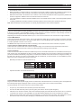
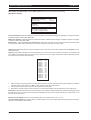
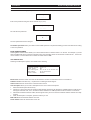
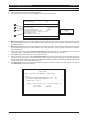
GO TO
The Go To key allows you to select a date and time and play back recorded video. To replay a recorded video from specific time
and date:
1.
Press the GO TO key. The Go to... entry window will open.
Go to ...
18/04/2005
2.
17:31:57
The first field dd (18 in the example above) will be selected. Use the up/down arrow keys (or number keys 1 to 10 where
the number 10 key will enter a ‘0’) to enter the number of the day. Press the right arrow key to select the next field and edit
as above.
3.
Continue until the desired date and time have been entered.
4.
Press the enter key. The video will be replayed from the selected time and date.
18
User Manual
Baxall Vivid Digital Video Recorder
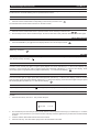
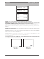
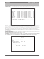
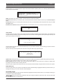
EVENT
The event key calls up any saved system, alarm or motion detection events which can then be selected and replayed. To select
an event:
1.
Press the event key and enter the password. This will open the View events log at the filter page. Use the filter page if
required to filter the event log in order to more easily locate the desired event. Events marked with a X will be passed by
the filter page. For example, to view only Alarm type events in the log, clear the X from everything in the Filters list except
Alarm.
View events log
Filters
Cameras
Alarms
Motion
Marked blocks
Video Loss
Shutdown
Config change
Unit password incorrect
Remote password incorrect
Exported data
[X]
[ ]
[ ]
[ ]
[ ]
[ ]
[ ]
[ ]
[ ]
1 2
3 4 5 6 7 8 9 10 11 12 13 14 15 16
[X] [X] [X] [X] [X] [X] [X] [X] [X] [X] [X] [X] [X] [X] [X] [X]
Events with no associated camera
Time
After time
Before time
[ ]
[ ]
Back to menus
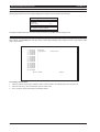
2,
[X]
View events
Using the arrow keys, select View events and press the enter key. The View events page will change to show any saved
events corresponding to the filter criteria entered.
View events log
Alarm
Alarm
Motion
Motion
Motion
Motion
Motion
1
1
1
1
1
1
1
18/04/2005
18/04/2005
18/04/2005
18/04/2005
18/04/2005
19/04/2005
19/04/2005
15:57:20
16:31:25
16:52:21
16:54:12
16:55:01
10:51:49
10:53:21
18/02/2005
18/02/2005
18/02/2005
18/02/2005
18/02/2005
19/02/2005
19/02/2005
15:57:49
16:40:51
16:52:51
16:54:42
16:55:31
10:52:18
10:53:43
Play Del Exp
Play Del Exp
Del
Del
Play Del Exp
Play Del Exp
Del
Showing events 1 - 7 of 7 (Page1/1)
Clear log
Return to filters
Next page
3.
Events which can be replayed will have Play in the description line. To play such an event, use the arrow keys to select
play for the event. Press the enter key. The selected event will be played back on the selected monitor.
4.
Events can also be deleted by selecting Del, or exported to the designated export device e.g. USB memory stick by
selecting Exp - see Appendix 6 - Exporting Files to CD and DVD.
19
Baxall Vivid Digital Video Recorder
User Manual
SEQUENCES
The Vivid DVR can display all of the cameras connected to it in sequence. Each camera will be displayed on the active monitor
for a period of time set by the Dwell time parameter. To start camera sequencing:
1.
Select a camera (sequencing can start from any camera) by pressing the corresponding number key.
2.
Press the sequence key.
To stop seqencing:
1.
Press the sequence button, or select a camera for full screen viewing by pressing a camera number key.
PICTURE IN PICTURE
The Vivid DVR has a picture-in-picture feature. To activate picture-in-picture (PIP) mode:
1.
Press the PIP key.
2.
The display will change to the picture-in-picture mode.
To change the size of the PIP:
1. Press the PIP key to change the size of the PIP display. Each press of the PIP key changes the PIP display to one of three
sizes.
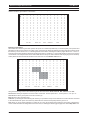
To change the position of the PIP display:
1. Use the left/right and up/down arrow keys to move the PIP as shown below.
To change the camera of the PIP display:
To change the camera which is displayed by the PIP, the PIP area of the display (usually referred to as a cameo) needs to be
selected.
1.
20
Press the enter key. This will superimpose a reverse highlighted * on the main camera display (camera 2 in the example
below).
User Manual
Baxall Vivid Digital Video Recorder
PICTURE IN PICTURE
2.
Use the arrow keys to move the * to select the PIP. This is now the active cameo (camera 1 in the example below).
3.
Press the camera number key for the camera you want to display in the PIP area.
4.
Press the enter key to exit cameo selection. The * will disappear.
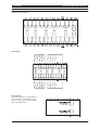
MULTISCREEN
The Vivid DVR can display cameras in multiscreen mode. The individual areas of a multiscreen display are called cameos.
To enter mulitscreen mode:
1.
Press the MULTI key.
2.
The first press will select quad mode. Subsequent presses of the MULTI key will cycle through the multiple displays
available for the model of Vivid DVR you are using:
6 camera model
10 camera model
16 camera model
When a multiscreen display is being viewed, it is possible to select which camera is displayed in each cameo of the display.
This is done by selecting an active cameo and then selecting which camera is assigned to the cameo.
1.
Select active cameo mode by pressing the enter key whilst in a multiscreen display. A reverse highlighted * will be displayed
in the cameo indicating that it is selected and the active cameo.
2.
Using the arrow keys, move the * to the cameo you wish to change. This is indicated by the * within the selected cameo.
3.
Press the desired camera number key. The selected camera will be shown within the selected cameo.
21
Baxall Vivid Digital Video Recorder
User Manual
TELEMETRY
The Baxall Vivid DVR is capable of controlling PTZ and dome cameras which are connected to it. In order to control such
cameras, the Vivid DVR is used in telemetry mode.
To enter telemetry mode:
1. Select the PTZ or dome camera connected to the unit by pressing the appropriate camera key.
2.
Press the Enter key then the MON key to activate telemetry mode.
FOLLOWED BY
To pan or tilt the camera:
When in telemetry mode, the arrow keys are used to pan and tilt the selected PTZ camera. A single keypress will pan or tilt the
camera at the slowest speed; a double keypress in quick succession will pan or tilt the camera at medium speed; a triple
keypress in quick succession will pan or tilt the camera at high speed. Four key presses in quick succession will pan or tilt the
camera at full speed.
To focus the camera:
When in telemetry mode, the Enter and Menu keys are used to adjust camera focus.
To zoom in or out:
When in telemetry mode, the Event and Go To keys are used to control the zoom in or zoom out function of the camera lens.
To program a preset:
1.
Select the camera, enter telemetry mode and move it to the required postion.
2.
Press and hold a numbered camera key (1 to 6, or 1 to 10, or 1 to 16) to store the preset. The message ‘Preset stored’ will
be displayed when the preset has been programmed.
Note: The number of presets that can be stored for PTZ/Dome cameras is dependent on the Vivid DVR in use. For example,
a six way unit can store six presets per camera; a 10 way unit can store 10 presets and a 16 way unit can store 16 presets.
Recalling a preset:
1.
Select the camera and enter telemetry mode.
2.
Press the appropriately numbered key (1 to 6, or 1 to 10, or 1 to 16) to recall the required preset.
22
User Manual
Baxall Vivid Digital Video Recorder
SYSTEM FUNCTIONS
Introduction
This section covers more detailed aspects of the setup and operation of the Vivid DVR. It assumes a familiarity with the basic
function of the Vivid DVR, covered in the preceding sections of the manual, along with a familiarity with navigating the Vivid
DVR menu system.
HARDWARE SETUP MENU
This menu configures the Vivid DVR to match the system components connected to it. The top level entries in this menu
branch are:
•
Cameras
•
Disks
•
Relays
•
Alarms
•
Networking
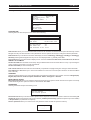
CAMERAS
Selecting the Camera menu will display a page similar to the following (Note this image shows options that might not initially be
visible when the page is opened):
Camera Setup - Camera 1
Camera name
Camera 1
Camera recording
[X]
Camera recording
[X]
Camera enabled
[X]
Hidden camera
Input terminated
[ ]
[X]
Daytime recording
Normal pics/sec
Alarm pics/sec
Activity pics/sec
[X]
06 / 6
06
06
Dome camera
Dome ID
Bus
[X]
0001
RJ45 connector
Night recording
Normal pics/sec
Alarm pics/sec
Activity pics/sec
[X]
01 / 1
01
01
Trigger relay 1
Trigger relay 2
Send email
Display main monitor alert
Display spot monitor alert
Sound buzzer
Light alarm LED
Auto-copy event
Pre video loss buffer
[ ]
[ ]
[ ]
[X]
[ ]
[X]
[X]
[X]
10
Colour
Saturation adjust
Contrast adjust
Brightness adjust
Hue adjust
Auto-detect
100
100
100
100
Weekend recording
Normal pics/sec
Alarm pics/sec
Activity pics/sec
[X]
01 / 1
01
01
Picture size
06k
Camera event mode
Interleaved
Video loss action >>
Min recording time:
Max recording time:
Exit
Record rate >>
89 days
106 days
Next page
Min recording time:
Max recording time:
Exit
89 days
106 days
Next page
Selecting Video loss action will reveal these options:
Camera name
Allows the entry of a unique camera title. Camera names can contain up to nine characters.
To Edit the camera name:
1.
With the camera name field selected, press the Enter key. The background colour of the camera number field will change.
2.
Using the up or down arrow keys, the first character of the title can be changed. Available options include A to Z in both
upper and lower case, 0 to 9, and various ASCII characters. A USB keyboard can also be used for ease of operation.
3.
After the first character has been edited, use the right arrow key to move to the next character. Edit the character as in step
2 above.
4.
When the name has been edited, press the enter key to exit edit mode. The background colour of the camera number field
will change.
Camera enabled
This menu option enables or disabled the selected camera. Default [X] (enabled)
23
Baxall Vivid Digital Video Recorder
User Manual
CAMERAS
Hidden camera
Allows the selected camera to be hidden from view on the monitor. It will still be recorded. Default is hidden mode disabled.
Input terminated
Selects whether the camera input is terminated [X] or not. Default is terminated. Highlight the field and use the enter key to
enable/disable termination.
Dome camera
If the camera connected to the input is a dome camera, selecting this menu option allows you to configure the camera.
Selecting [X] (enabled) reveals two further options: Dome ID and Dome bus.
Dome ID allows a number from 1 to 16 to be entered as an ID for the selected camera. To change the ID, highlight the field and
press the enter key. The field will change colour. Use the up/down arrow keys to select an ID number. Press the enter key when
finished.
Dome bus determines how the camera is connected to the Vivid DVR. Options are RJ45 connector or Screw connector.
Highlight the field and use the enter key to select an option.
Colour
This menu option allows you to select from Colour, Black & white or Auto-detect. Highlight the field and use the enter key to
select an option. Auto-detect will automatically detect whether cameras connected are black and white or colour.
Saturation adjust, Contrast adjust, Brightness adjust and Hue adjust
These four menu items allow the cameras saturation, contrast, brightness and hue parameters to be adjusted. To adjust a
parameter, highlight the field and press the enter key. The field will change colour. Use the up/down arrow keys to change the
selected parameter (001 to 200). Press the enter key when finished. Changes to picture quality will only be visible once the
menu has been exited.
Picture size
Sets the target compressed image file size (which determines recorded picture quality). Individually selectable per camera. To
adjust picture size, highlight the field and press the enter key. The field will change colour. Use the up/down arrow keys to
change the value (03KB to 60KB). Press the enter key when finished.
Camera event mode
Allows you to specify the way in which event cameras are recorded. Camera events are defined as cameras in an alarm
condition or where motion detection has been triggered. Use the enter key to select from Interleaved, Normal or Exclusive.
The Interleaved setting will record event cameras and non-event cameras. The event cameras will be interleaved between the
non-event cameras. For example:
Event cameras
4, 6
Non-event Cameras
1, 2, 3, 5, 7
Resulting Record Sequence
1, 4, 6, 2,
6, 1, 4, 6...etc.
4,
6,
3,
4,
6,
4,
4,
6,
5,
4,
6,
6,
4,
6,
7,
4,
The Exclusive setting will only record cameras in an event condition. All other cameras will be omitted from recording while an
event is active.
The Normal setting will record cameras in order e.g. 1, 2, 3, 4, 5, 6, 7, 8.... etc.
Camera recording
The selected camera will only be recorded if this menu option is set to [X] (enabled). Highlight the field and use the enter key
to enable/disable camera recording. Default is enabled.
RECORD RATE SETTINGS
The Daytime recording options are only visible if camera recording is enabled. To change the setting, highlight the field and use
the up/down arrow keys to change the value. Settings available are 1 to 25 pictures per second depending on the number of
cameras connected.
Daytime recording This option allows you to enable or disable daytime recording (default Enabled).
Normal pics/sec This sets the picture recording rate during normal recording (default 25pps).
Alarm pics/sec This sets the picture recording rate if the camera goes into alarm mode (default 3pps).
Activity pics/sec This sets the picture recording rate if the camera is triggered by motion detection (default 3pps).
The Night recording and Weekend recording settings are made in exactly the same way as the Daytime recording settings.
Note however, that they will only be visible if they have been set to Yes in the Recording setup > Schedule menu.
24
User Manual
Baxall Vivid Digital Video Recorder
CAMERAS
VIDEO LOSS ACTION
The video loss action options are accessed by selecting the Video loss action>> field on the Camera setup page and pressing
the enter key.
Trigger relay 1
When an event is detected by the camera, this option allows you to initiate the action set for Relay 1 (see Relays). Options are
enabled [X] or disabled (default disabled).
Trigger relay 2
When an event is detected by the camera, this option allows you to initiate the action set for Relay 2 (see Relays). Options are
enabled [X] or disabled (default disabled).
Send email
When an event is detected by the camera, this option allows you to send an email. Options are enabled [X] or disabled (default
disabled). Email parameters are set up under Hardware setup > Networking > Email setup. Email will only work if the Vivid DVR
is connected to a network.
Display main monitor alert
When an event is detected by the camera, this option allows you to display an alert on the main monitor. Options are enabled
[X] or disabled (default enabled).
Display spot monitor alert
When an event is detected by the camera, this option allows you to display an alert on the spot monitor. Options are enabled
[X] or disabled (default disabled).
Sound buzzer
When an event is detected by the camera, this option allows you to sound an audible warning using the unit’s built in buzzer.
Options are enabled [X] or disabled (default enabled).
Light alarm LED
When an event is detected by the camera, this option allows you to illuminate the Alarm led on the front panel of the Vivid DVR.
Options are enabled [X] or disabled (default enabled).
Auto-copy event
When an event is detected by the camera, this option allows you to automatically copy event data, as it happens, to a
predetermined place which is set up within the disk manager menu. Options are enabled [X] or disabled (default enabled).
Other Camera Setup page information
Min recording time provides an estimate of the minimum recording time available with the current record settings.
Max recording time provides an estimate of the maximum recording time available with the current record settings.
Next page opens the camera setup page for the next camera.
Exit closes the camera setup page and returns to the Hardware setup menu.
25
Baxall Vivid Digital Video Recorder
User Manual
DISKS
Selecting Hardware setup > Disks will open the Disks menu.
Event partition
10%
Disk record mode
Looping
Timed expiry on
No
Stop USB devices
Disk Manager
Event partition
This setting determines the percentage of disk space that will be allocated to event recording. Select between 1 and 50%
Disk record mode
This setting determines the way that data is written to the disk(s). Looping will overwrite data when the disk becomes full.
Linear will fill the disk(s) to capacity without overwriting previously recorded data and a warning will be displayed when the
disks are full or nearly full.
Timed expiry on
Ensures data is overwritten after a predetermined period. Selecting Yes opens the Timeout period option:
Event partition
10%
Disk record mode
Looping
Timed expiry on
Yes
Timeout period
365 days
Stop USB devices
Disk Manager
Timeout period
The timeout period can be set by selecting the field and pressing the enter key. Use the up/down keys to select a value for the
timeout period in days. Press enter to finish.
Stop USB devices (only visible if a USB device is connected to the front panel’s USB port)
Selecting this menu item will stop all USB devices connected to the Vivid DVR.
Disk Manager
Selecting the Disk manager field and pressing the enter key will open the disk manager pages. A sample page is shown below.
Disk Manager
1
2
Size
163.9G
163.9G
Used
91%
90%
Status
In use
In use
Erase
Erase
Showing internal disks 1 - 2 of 2
Back to Menus
Next page
The page shows the size of each installed disk, the percentage of disk space used and the status of each disk. In addition, it is
possible to erase the data from each disk. To erase a disk:
1.
Highlight the Erase field for the disk you want to erase and press the enter key.
2.
The message ‘Are you sure? Data will be permanently deleted!’ will be displayed.
3.
Use the left/right arrow keys to select Yes or No and press the enter key.
WARNING: Selecting Yes will permanently erase all recorded data which will no longer be available.
26
User Manual
Baxall Vivid Digital Video Recorder
DISKS
Selecting Next page from the first disk manager page will open the USB devices page. This page will display any USB devices
connected to the Vivid DVR.
Disk Manager
ID
Showing USB devices 0 - 0 of 0
Previous page
Back to Menus
Next page
Set status for this device
Erase
Export destination
Stop
Unused
Exit
Set status for this device selecting Export destination will reveal the ‘Set status for this device’ menu options.
Erase erases data from a USB device such as a memory stick
Export destination sets the connected USB device as the export destination for exporting configuration settings etc.
Stop stops the connected USB devices
Unused the device is not used.
Exit closes the Set status for this device menu options.
Selecting Next page from the second disk manager page will open the SCSI devices page. This page will display any SCSI
devices connected to the Vivid DVR.
Disk Manager
ID
LUN
Status
Showing SCSI devices 0 - 0 of 0
Previous page
Back to Menus
Set status for this device
Erase
Export destination
Stop
Unused
Exit
Connecting SCSI devices
1.
Ensure that the Vivid DVR is disconnected from the power.
2.
Connect a supported SCSI device to the 50-pin SCSI connector on the rear panel.
3.
Power up the SCSI device
4.
Power up the Vivid DVR.
Note: When the internal hard drive(s) are full, data will be written to the connected SCSI device (provided that the Vivid DVR is
set to record in linear mode).
WARNING: Do not connect or disconnect SCSI devices while the Vivid DVR is powered up.
27
Baxall Vivid Digital Video Recorder
User Manual
RELAYS
This menu allows you to configure the two built in relays.
Relay number allows you to select either relay 1 or relay 2. To change the relay number, highlight the field and press the enter
key. Next, use the up/down arrow keys to select 1 or 2. Press enter when selection is complete.
Relay number 1
Relay action Open
Relay action allows you to select what the relay will do when it is triggered. To change the action, highlight the field and press
the enter key.
Relay number 1
Relay action Open
Open
Close
Open 1/2s
Close 1/2s
Use the up/down arrow keys to select from:
Open an event (alarm, motion detection, etc.) will cause the relay to open
Close an event (alarm, motion detection, etc.) will cause the relay to close
Open 1/2s an event (alarm, motion detection, etc.) will cause the relay to open for a period of 1/2 second
Close 1/2s an event (alarm, motion detection, etc.) will cause the relay to close for a period of 1/2 second
Press the enter key when the selection has been made.
ALARMS
This menu allows you to configure the Baxall Vivid DVR’s alarm system.
Alarm input
Enabled
1
No
Alarm input allows you to select alarm 1 to 16. To change the alarm input, highlight the field and press the enter key. Next, use
the up/down arrow keys to select 1 to 16 (or camera number keys 1 to 9). Press enter when selection is complete.
Enabled allows you to enable or disable the selected alarm input. If Enabled is set to Yes, more options are revealed:
Alarm input
1
Enabled
Yes
Setup
Normally closed
Alarm action
Test alarm
Setup allows you to select whether the alarm is either Normally open or Normally closed. Select the field and press the enter
key. Use the up/down arrow keys to select Normally open or Normally closed. Press the enter key when finished.
Alarm action when selected, additional menus allow you to set the properties for the selected alarm.
Alarm input 1
Enabled
Yes
Setup
Normally closed
Alarm action
Test alarm
Trigger relay 1
Trigger relay 2
Send email
Display main monitor alert
Display spot monitor alert
Sound buzzer
Light alarm LED
Auto-copy event
Linked
Camera
Camera
Switch
Switch
to camera
number
preset
main monitor
spot monitor
Action length
Record time
28
No
No
No
Yes
No
Yes
Yes
No
Yes
1
1
No
No
Fixed time
30s
User Manual
Baxall Vivid Digital Video Recorder
ALARMS
Trigger relay 1
When the selected alarm is triggered, this option allows you to initiate the action set for Relay 1 (see Relays). Options are Yes
or No.
Trigger relay 2
When the selected alarm is triggered, this option allows you to initiate the action set for Relay 2 (see Relays). Options are Yes
or No.
Send email
When the selected alarm is triggered, this option allows you to send an email if email is set up and the unit is connected to a
network. Options are Yes or No.
Display main monitor alert
When the selected alarm is triggered, this option allows you to display an alert on the main monitor. Options are Yes or No.
Display spot monitor alert
When the selected alarm is triggered, this option allows you to display an alert on the spot monitor. Options are Yes or No.
Sound buzzer
When the selected alarm is triggered, this option allows you to sound an audible warning using the unit’s built in buzzer.
Options are Yes or No.
Light alarm LED
When the alarm is triggered, this option allows you to illuminate the Alarm led on the front panel of the Vivid DVR. Options are
Yes or No.
Auto-copy event
When the selected alarm is triggered, this option allows you to automatically copy event data, as it happens, to a predetermined
place which is set up within the disk manager menu. Options are Yes or No. If the option is set to Yes, the Pre alarm buffer is
displayed. This is a buffer which will record video for up to 10 seconds prior to the alarm, If an alarm is actioned, then this data
is available to store onto the disk drive as a pre alarm state. Select 1 to 10s.
Linked to camera allows you to link the alarm event to a camera. When the alarm is triggered, the selected camera linked to
the alarm will be displayed on either the main monitor or spot monitor depending on the settings chosen. Options are Yes or
No. If the option is set to Yes, additional menu items will be displayed.
Camera number (only visible if Linked to camera is set to Yes) allows you to select one of the cameras connected to the unit.
Options are cameras 1 to 16.
Camera preset (only visible if Linked to camera is set to Yes and connected camera is a PTZ unit) allows you to select a preset
number (that has been previously programmed) for a suitable PTZ/dome camera connected to the input. Options are preset 1
to 16.
Switch main monitor (only visible if Linked to camera is set to Yes) if set to Yes, the camera will be displayed on the main
monitor. Options are Yes or No.
Switch spot monitor (only visible if Linked to camera is set to Yes) if set to Yes, the camera will be displayed on the spot
monitor. Options are Yes or No.
Action length allows you to select how long the alarm event will occur. Choose from:
Fixed time the alarm will continue for a specified time. If this item is selected, the Record time menu item will appear allowing
you to enter the length of time from 1 to 600 seconds.
Until cleared the alarm will continue until manually reset by the user.
Until alarm stops the alarm will continue until the process causing the alarm stops.
Record time allows you to set a time period during which video will be recorded at the selected alarm rate before returning to
normal record speed. Select from 1 to 600 seconds
Test alarm
Allows you to test the alarm action previously set up. Highlight the field and press the enter key. Select Yes or No.
29
Baxall Vivid Digital Video Recorder
User Manual
NETWORKING
Selecting Networking from the Hardware setup menu will open a menu similar to one of the following:
Ethernet enabled
Yes
Ethernet enabled
Yes
Use DCHP
IP addresses
Email setup
Local domain
Bandwidth limit
No
No
baxall.com
50%
Use DCHP
IP addresses
Email setup
Local domain
Bandwidth limit
baxall.com
50%
Use proxy server
Proxy server
Proxy port
Proxy username
Proxy password
Yes
(not set)
8080
(not set)
(not set)
Use proxy server
Proxy server
Proxy port
Proxy username
Proxy password
Yes
(not set)
8080
(not set)
(not set)
RS485 usage
Dome protocol (RS485)
Dome protocol (Screw)
RS232 setup
Dome control
Baxall Prodome
Baxall Prodome
RS485 usage
RS485 address
RS485 baud rate
Dome protocol (Screw)
RS232 setup
External keyboard
1
9600
Baxall Prodome
MAC address
MAC address
RS485 useage set to Dome control
RS485 useage set to External keyboard
Ethernet enabled allows you to enable or disable Ethernet connectivity. Options are Yes or No. If the option is set to Yes,
additional menu items will be displayed.
Use DCHP (only visible if Ethernet enabled is set to Yes) allows dynamic IP addresses to be enabled or disabled. Options are
Yes or No.If yes is selected IP addresses will be obtained automatically; if no, IP addresses must be entered manually.
IP addresses (only visible if Ethernet enabled is set to Yes) allows you to manually set up IP addresses. Selecting this field and
pressing the enter key will open the following menu:
IP address
Subnet mask
Default gateway
DNS server
192.168.000.231
255.255.255.000
192.168.000.250
192.168.000.250
NTP servers
130.88.200.98
xxx.xxx.co.uk
(Not set)
(Not set)
(Not set)
To edit an address, select the field to be edited using the up/down arrow keys and then press the enter key. The selected
address will be opened in a sub menu with the first three numbers selected (IP addresses can only be edited manually if Use
DCHP is set to no):
192.168.000.231
Use the up/down arrow keys or camera number keys (1 to 9) to change the selected numbers. When finished, use the right
arrow key to select the next three numbers in the address. Again, use the up/down arrow keys or camera number keys to
change the numbers. Carry on in this manner until the address has been fully entered. Press the enter key to quit editing.
Email setup (only visible if Ethernet enabled is set to Yes) allows you to configure the settings required for the Send email
action. To edit the properties, highlight the field and press the enter key. A sub menu similar to the following will appear:
SMTP
SMTP
SMTP
From
server
port
domain
address
Email addresses
Send test mail
30
207.228.254.011
25
baxall.com
[email protected]
[email protected]
(Not set)
(Not set)
(Not set)
(Not set)
User Manual
Baxall Vivid Digital Video Recorder
NETWORKING
SMTP Server allow you to set up the SMTP properties of the email. Editing is achieved in exactly the same way as editing an
IP address above.
SMTP Port allows the SMTP port number to be selected. Select the field and press the enter key. Use the up/down keys to
select the port number (1 to 65535)
SMTP Domain allows you to enter the SMTP domain. Select the field and press the enter key. The domain will be opened in a
sub menu with the first character selected:
baxall.com
To edit the SMTP Domain:
1.
Use the up or down arrow keys to change the selected first character of the domain. Available options include A to Z in both
upper and lower case, 0 to 9, and various ASCII characters. A USB keyboard can also be used for convenience.
2.
After the first character has been edited, use the right arrow key to move to the next character. Edit the character as in step
1 above.
3.
When the domain is complete, press the enter key to exit.
From Address allows you to enter an address that will be included in the email’s ‘From’ line. Selection and editing is done in the
same way as the SMTP domain, above.
Email addresses these fields allow you to enter up to five email addresses. Selection and editing is done in the same way as
the SMTP domain, above. A maximum of five email addresses can be set up.
Local domain (only visible if Ethernet enabled is set to Yes) allows you to set the local domain name. Selection and editing is
done in the same way as the SMTP domain, above.
Bandwidth limit (only visible if Ethernet enabled is set to Yes) allows you to set the maximum network bandwidth used by the
Vivid DVR. Values are 5% to 100%.
Use proxy server allows you to enable or disable a proxy server. Options are Yes or No. If the option is set to Yes, additional
menu items will be displayed.
Proxy server (only visible if Use proxy server is set to Yes) allows you to enter the proxy server’s name. Editing is done in the
same way as the SMTP domain, above.
Proxy port (only visible if Use proxy server is set to Yes) allows you to enter the proxy server’s port. Select the field and press
the enter key. Use the up/down arrow keys to change the port number. Press the enter key when finished.
Proxy username and Proxy password (only visible if Use proxy server is set to Yes) allow the proxy username and password
to be entered. Editing is done in the same way as for SMTP Domain above.
RS485 Usage allows you to select what the RS485 port will be used for. Select the field and press the enter key. Use the up/
down arrow keys to select either Dome control or External keyboard. Press the enter key when finished.
RS485 address (only visible if External keyboard is selected in the RS485 usage field) Allows you to enter the address of the
external keyboard. Select 1 to 100.
Dome protocol (RJ45) allows you to select the dome protocol for use with the RJ45 connector on your Vivid unit. Select the
field and press the enter key. Use the up/down arrow keys to select either Pelco D (or any dome that supports Pelco D
protocol), American Dynamics or Baxall Prodome. Press the enter key when finished.
Dome protocol (screw) allows you to select the dome protocol for use with the screw connectors on your Vivid unit. Select the
field and press the enter key. Use the up/down arrow keys to select either Pelco D (or any dome that supports Pelco D
protocol), American Dynamics or Baxall Prodome. Press the enter key when finished.
RS232 Setup allows you to set the RS232 port options. Select the field and press the enter key to open the RS232 setup menu.
Baud rate
Bits
Parity
Stop bits
Flow control
57600
8
None
1
None
Baud rate select from 1200, 2400, 4800, 9600, 19200, 38400, 57600, or 115200.
Bits select from 5, 6, 7 or 8.
Parity select from None, Even or Odd.
Stop bits select from 1 or 2.
Flow control select from Hardware, Software or None.
MAC address shows the Vivid unit’s MAC address (information only)
31
Baxall Vivid Digital Video Recorder
User Manual
CONFIGURE DISPLAY
This menu item allows configuration of the monitors that are connected to the Vivid DVR. The top level menu is divided into
Main monitor and Spot monitor. Selecting Main monitor will open a menu similar to the following:
Main Monitor Settings
Full screen interlace
Multiscreen interlace
Monitor type
Yes
Yes
Overscan
Sequenced
Sequence
Dwell time
Yes
4s
Show on-screen display
On-screen display setup
On-screen display offsets
Yes
Full screen interlace interlaced images are made of two fields. In full screen this will give the impression of a higher resolution
and sharper image. Select either Yes or No.
Multiscreen interlace interlaced images are made of two fields. In Multiscreen this will give a sharper image but may appear
to shimmer. Select either Yes or No.
Monitor Type Select from Overscan or Underscan to suit the type of monitor you are using. The difference between these
two options will produce either a stretched or normal size image to suit the type of monitor used.
Sequenced activates the display to sequence between all the cameras that have been enabled within the Sequence menu.
Select Yes or No.
Sequence (only visible if Sequenced is set to Yes) allows you to select which of the cameras connected to the Vivid DVR will
be included in the sequence when the sequence key is pressed on the front panel. Selecting the field and pressing the enter
key will open a menu similar to the following:
Camera1
Camera2
Camera3
Camera4
Camera5
Camera6
Camera7
Camera8
Camera9
Camera10
Camera11
Camera12
Camera13
Camera14
Camera15
Camera16
Yes
Yes
Yes
Yes
Yes
Yes
Yes
Yes
Yes
Yes
Yes
Yes
Yes
Yes
Yes
Yes
1.
Select a camera using the up/down arrow keys and press enter. Use the up/down arrow keys to select Yes to include the
selected camera in the sequence, or No to omit it. Press the enter key when finished.
2.
Use the up/down arrow keys to select the next camera and follow step 1.
3.
When all the cameras required in the sequence (or not) have been edited, press the left arrow key to exit the menu.
Dwell time (only visible if Sequenced is set to Yes) allows you to select the time period that each camera will be displayed until
the sequence moves on to the next camera. Select the field and press enter. Use the up/down arrow keys to select from 1 to 60
seconds. Press enter to exit.
Show on-screen display turns the on-screen display (date, time, camera names, etc.) on or off.
On-screen display setup (only visible if Show on-screen display is set to Yes). Selecting the field and pressing the enter key
will open a menu similar to the following:
32
User Manual
Baxall Vivid Digital Video Recorder
CONFIGURE DISPLAY
Show date
Location
Foreground colour
Inverse
Yes
Top right
White
No
Show time
Location
Foreground colour
Inverse
Yes
Top right
White
No
Screen window
1
Show camera name
Show camera number
Location
Foreground colour
Inverse
Yes
Yes
Bottom left
White
No
Show extra info
Location
Foreground colour
Inverse
Bottom left
Green
No
Show date allows you to select whether the date will be displayed or not. Select from Yes or No.
Location determines the location of the date. Select the field and press the enter key. Use the up/down arrow keys to select
from Top left, Top right, Bottom left or Bottom right. Press the enter key when selection is complete.
Foreground colour determines the colour of the text (or background colour if Inverse is set to Yes). Use the up/down arrow
keys to select from White, Blue, Green, Cyan, Red, Magenta or Yellow. Press the enter key when selection is complete.
Inverse inverts the text colour with the background e.g. if text is set to white, selecting inverse will display black text on a white
background.
Show time allows you to select whether the time will be displayed or not. Select from Yes or No. All other editable parameters
are the same as for Show date above.
Show camera name allows you to select whether the camera name will be displayed or not. Select from Yes or No. All other
editable parameters are the same as for Show date above.
Show extra info allows you to select whether the information such as alarms, video loss, etc. will be displayed or not. Select
from Yes or No. All other editable parameters are the same as for Show date above.
On-screen display offsets
Top offset, Bottom offset, Left offset and Right offset. These settings allow the absolute positions of the on-screen captions
to be moved by increments of +3 to -3. Negative values move the captions towards the centre of the display. Positive values
move the captions away from the centre as shown below.
Bottom offset = 0
Bottom offset = -3
Right offset = 0
Right offset = -3
33
Baxall Vivid Digital Video Recorder
User Manual
CONFIGURE DISPLAY
Spot Monitor Settings
Selecting Spot monitor from the Configure display menu will open a menu similar to the following:
Monitor type
Overscan
Sequenced
Sequence
Dwell time
Yes
4s
On-screen display setup
On-screen display offsets
All settings available within this menu are exactly the same as for the Main Monitor Settings menu.
ALARM STATUS
These pages allow you to manually acknowledge alarm or motion detection events. The default page shows information for
Alarm events. Selecting Motion on this page opens a similar page detailing motion detection events. A typical alarm status
page is shown below.
Alarm Status
1
2
3
4
5
6
7
8
9
10
11
12
13
14
15
16
Alarming
Alarming
Disabled
Disabled
Disabled
Disabled
Disabled
Disabled
Disabled
Disabled
Disabled
Disabled
Disabled
Disabled
Disabled
Disabled
Timed Out
In progress
-
Clear alarm
Back to menus
Motion
To manually clear an alarm
1.
Used the up/down arrow keys to select the alarm or motion event to be cleared (if there is more than one)
2.
Press the enter key to clear the selected alarm or motion event.
3.
The ‘In progress’ caption will change to ‘Manually cleared’.
34
User Manual
Baxall Vivid Digital Video Recorder
RECORDING SETUP
The recording setup menu item opens the following menu:
Turbo mode
Schedule
Motion detection
Sound
RS232 Data
TURBO MODE
When selected, Turbo mode permits recording at a rate of up to 100 pics/sec (VIVID+ units only)
SCHEDULE
Selecting schedule opens a sub menu similar to the following:
Set night period
Night period start
Yes
19:30:00
Night period end
08:00:00
Set weekend period
Weekend period start
Weekend period end
Yes
Friday 19:30:00
Monday 08:00:00
Set night period is used to define a time frame during which the Vivid DVR will not record. The time is entered as a start and
end time between which recording is disabled. Select Yes or No. Each camera can be selected individually.
Night period start (only visible if Set night period is set to Yes) allows you to enter the start time for the night period. To set the
night period time:
1.
2.
Select the field and press the enter key.
The time field will be opened with the ‘hours’ field highlighted.
19:30:00
3.
4.
5.
6.
Use the up/down arrow keys (or the camera number keys 1 to 9) to change the hours setting.
When finished, press the right arrow key to select the minutes field. Use the up/down arrow keys to change the minutes.
Press the right arrow key to select the seconds field (if required). Use the up/down arrow keys or number keys to change.
When the required time has been entered, press the enter key to finish.
Night period end (only visible if Set night period is set to Yes) allows you to enter the night period end time. Editing is done in
the same way as for Night period start above.
Set weekend period is used to define a time frame during which the Vivid DVR will not record. The time frame is entered as a
start and end time between which recording is disabled. Select Yes or No. Each camera can be selected individually.
Weekend period start (only visible if Set weekend period is set to Yes) allows you to enter the start time for the weekend
period. Editing is done in the same way as for Night period start above.
Weekend period end (only visible if Set weekend period is set to Yes) allows you to enter the weekend period end time. Editing
is done in the same way as for Night period start above.
MOTION DETECTION
Selecting Motion detection from the recording menu will open the motion detection menu similar to the diagram shown below:
Camera number
Active
Setup grid
Motion action
Motion tracking
1
Yes
Status
Action status
Not detected
None
10s
Camera number allows you to select the camera that will have motion detection applied to it. Use the enter key and up/down
arrow keys to select the camera.
Active enables or disables motion detection for the selected camera. Select Yes or No.
Setup grid (only visible if Active is set to Yes) selecting Setup grid will superimpose a grid over the image from the selected
camera. The grid allows you to select the areas of the scene where motion detection is to be activated.
35
Baxall Vivid Digital Video Recorder
User Manual
RECORDING SETUP
The default grid is shown below. A ‘0’ shows whether that particular grid location is disabled (motion detection inactive). The
default is for all the grid locations to be inactive.
0
0
0
0
0
0
0
0
0
0
0
0
0
0
0
0
0
0
0
0
0
0
0
0
0
0
0
0
0
0
0
0
0
0
0
0
0
0
0
0
0
0
0
0
0
0
0
0
0
0
0
0
0
0
0
0
0
0
0
0
0
0
0
0
0
0
0
0
0
0
0
0
0
0
0
0
0
0
0
0
0
0
0
0
0
0
0
0
0
0
0
0
0
0
0
0
0
0
0
0
0
0
0
0
0
0
0
0
0
0
0
0
0
0
0
0
0
0
0
0
0
0
0
0
0
0
0
0
0
0
0
0
0
0
0
0
0
0
0
0
0
0
0
0
0
0
0
0
0
0
0
0
0
0
0
0
0
0
0
0
0
0
0
0
0
0
0
0
0
0
0
0
0
0
0
0
0
0
0
0
0
0
0
0
0
0
0
0
0
0
0
0
0
0
0
0
0
0
0
0
0
0
0
0
0
0
0
0
0
0
Set all
Clear all
Exit
Camera:1
Test
Enabling grid locations
When the motion detection grid is first opened, the top left ‘0’ is selected (indicated by a coloured square). The up/down and
left/right arrow keys can be used to move this ‘cursor’ around the grid. When the desired grid square has been selected, press
the enter key. The ‘0’ will turn into a ‘1’ indicating that the area is active. Pressing the enter key again will turn the ‘1’ into a ‘2’.
There are five levels of sensitivity selected by pressing the enter key. A setting of ‘1’ is the least sensitive to motion and ‘5’ is the
most sensitive. The example below shows an area that has been set up for motion detection with varying degrees of sensitivity.
Activity within this area will activate whatever action has been set in the Motion action menu.
0
0
0
0
0
0
0
0
0
0
0
0
0
0
0
0
0
0
0
0
0
0
0
0
0
0
0
0
0
0
0
0
0
0
0
0
0
0
0
0
0
0
0
0
0
0
0
0
0
0
0
0
0
0
0
0
0
0
0
0
1
1
1
0
0
0
0
0
0
0
0
0
0
0
1
2
2
0
0
0
0
0
0
0
0
0
0
0
1
3
3
0
0
0
0
0
0
0
0
0
0
0
0
0
5
5
3
0
0
0
0
0
0
0
0
0
0
0
5
5
3
0
0
0
0
0
0
0
0
0
0
0
3
2
1
0
0
0
0
0
0
0
0
0
0
0
1
1
1
0
0
0
0
0
0
0
0
0
0
0
0
0
0
0
0
0
0
0
0
0
0
0
0
0
0
0
0
0
0
0
0
0
0
0
0
0
0
0
0
0
0
0
0
0
0
0
0
0
0
0
0
0
0
0
0
0
0
0
0
0
Set all
Clear all
Exit
Camera:1
Test
Along the bottom edge of the motion detection grid are five menu items: Set all, Clear all, Exit, Camera:1 and Test.
Set all allows all the grid squares to be set to active. Press enter. The first press sets ‘1’, second press ‘2’, etc. up to ‘5’.
Clear all allows all the grid squares to be set to inactive (0).
Exit exits the motion grid setup page.
Camera:1 by selecting this field and using the enter key, it is possible to set up motion detection for all the cameras connected
to the Vivid DVR. Each press of the enter key selects the next camera and superimposes the grid over it.
Test allows you to test motion detection for areas set up on the grid. Selecting Test causes the grid overlay to disappear. If
motion is detected within the designated areas of the scene, a will appear at the triggered gridpoints. Select Stop test to exit.
*
36
User Manual
Baxall Vivid Digital Video Recorder
RECORDING SETUP
Motion action
This menu allows you to set up the event parameters that will be used if motion detection is activated for the selected camera.
Trigger relay 1
Trigger relay 2
Send email
Switch main monitor
Switch spot monitor
Display main monitor alert
Display spot monitor alert
Sound buzzer
Light alarm LED
Auto-copy event
No
No
No
No
No
No
No
No
Yes
No
Action length
Record time
Fixed time
30s
Trigger relay 1
When motion detection is activated, this option allows you to initiate the action set for Relay 1 (see Relays). Options are Yes or
No.
Trigger relay 2
When motion detection is activated, this option allows you to initiate the action set for Relay 2 (see Relays). Options are Yes or
No.
Send email
When motion detection is activated, this option allows you to send an email if email is set up and the unit is connected to a
network. Options are Yes or No.
Switch main monitor
If set to Yes, the camera will be displayed on the main monitor. Options are Yes or No.
Switch spot monitor
If set to Yes, the camera will be displayed on the spot monitor. Options are Yes or No.
Display main monitor alert
When motion detection is activated, this option allows you to display an alert on the main monitor. Options are Yes or No.
Display spot monitor alert
When motion detection is activated, this option allows you to display an alert on the spot monitor. Options are Yes or No.
Sound buzzer
When motion detection is activated, this option allows you to sound an audible warning using the built in buzzer. Options are
Yes or No.
Light alarm LED
When motion detection is activated, this option allows you to illuminate the Alarm led on the front panel of the Vivid DVR.
Options are enabled Yes or No.
Auto-copy event
When motion detection is activated, this option allows you to automatically copy event data, as it happens, to a predetermined
place which is set up within the disk manager menu. Options are Yes or No. If the option is set to Yes, the Pre alarm buffer is
displayed. This is a buffer which will record video for up to 10 seconds prior to the alarm, If an alarm is actioned, then this data
is available to store onto the disk drive as a pre alarm state. Select 1 to 10s.
Action length allows you to select how long the alarm event will occur. Choose from:
Fixed time the alarm will continue for a specified time. If this item is selected, the Record time menu item will appear allowing
you to enter the length of time from 1 to 600 seconds.
Until cleared the alarm will continue until manually reset by the user from the Alarm status page.
Until alarm stops the alarm will continue until the process causing the alarm stops.
Record time allows you to set a time period during which video will be recorded at the selected alarm rate before returning to
normal record speed. Select from 1 to 600 seconds
Motion tracking
This menu item allows you to select a period of time during which motion in the scene will be ignored. Select from 0 to 5
seconds.
Status and Action status are provided for information only. Messages are provided to indicate motion detection status and
action status.
37
Baxall Vivid Digital Video Recorder
User Manual
RECORDING SETUP
SOUND
The Sound menu item allows you set the parameters for the Vivid DVR’s sound inputs and outputs.
Sound recording active
Microphone sensitivity
Output volume
Input source
Play live sound
Yes
Medium
Medium
Microphone
Sound recording active allows you to enable or disable sound recording. Select Yes or No.
Microphone sensitivity adjusts the sensitivity of the microphone input. Select from Low, Medium or High.
Output volume adjusts the output volume of the audio out connector. Select from Low, Medium or High.
Input source allows you to select the source type of the audio input connector. Select from Microphone or Line in.
Play live sound allows you to enable or disable live sound playback. Select Yes or No.
RS232 DATA
This menu item allows you to select whether RS232 data will be recorded or not (from point-of-sale equipment etc.). Select
from Yes or No.
Record RS232 data
Yes
REPLAY
This menu allows you to select playback parameters such as sound and on-screen text. In addition, blocks may be marked for
playback or converted to events.
Play sounds
Show RS232 text
Yes
Yes
View events log
Mark block start
7/4/2005 10:34:54
Mark block end
7/4/2005 10:34:54
Length of marked block
0 Mbytes
Export marked block
Make marked block an event
Exported files
Play sounds enables or disables sound on playback. Select Yes or No.
Show RS232 text enables or disables RS232 text on playback (from point-of-sale equipment etc.). Select Yes or No.
View events log selecting View events log opens the Event filter page below.
View events log
Filters
Cameras
Time
Alarms
Motion
Marked blocks
Video Loss
Shutdown
Config change
Unit password incorrect
Remote password incorrect
Exported data
[X]
[X]
[X]
[X]
[X]
[X]
[X]
[X]
[X]
1 2
3 4 5 6 7 8 9 10 11 12 13 14 15 16
[X] [X] [X] [X] [X] [X] [X] [X] [X] [X] [X] [X] [X] [X] [X] [X]
Events with no associated camera
[X]
After time
Before time
10:34:54
10:34:54
[X]
[X]
Back to menus
07/04/2005
07/04/2005
View events
This page allows you to select various filtering criteria before viewing the log. Mark the events you wish to view with an [X] to
include them in the log listing. Select View events to view the log
38
User Manual
Baxall Vivid Digital Video Recorder
REPLAY
Shown below is a typical event log. Events can be removed from the log by using the up/down arrow keys to select Del and
pressing the enter key. The message ‘Are you sure? Data will be permanently deleted!’ will be displayed. Select Yes or No
to delete the event.
View events log
Setup change
Setup change
Setup change
Shutdown
Unit pass
Unit pass
Unit pass
Unit pass
Unit pass
Unit pass
Setup change
Setup change
Setup change
Video Loss
Setup change
1
-
18/02/2005
18/02/2005
18/02/2005
22/02/2005
22/02/2005
22/02/2005
22/02/2005
22/02/2005
22/02/2005
22/02/2005
22/02/2005
23/02/2005
23/02/2005
23/02/2005
23/02/2005
14:22:21
14:22:21
14:22:21
16:53:24
18:16:21
18:18:03
18:18:42
14:19:04
18:19:24
18:19:27
18:19:34
18:51:48
17:21:09
17:05:11
17:19:42
18/02/2005
18/02/2005
22/02/2005
22/02/2005
22/02/2005
22/02/2005
22/02/2005
22/02/2005
22/02/2005
22/02/2005
22/02/2005
22/02/2005
22/02/2005
23/02/2005
23/02/2005
14:22:24
14:25:06
16:53:04
18:16:14
18:18:52
18:18:24
18:19:11
18:19:43
18:19:40
18:19:24
18:20:27
18:25:22
17:30:18
17:31:44
17:44:24
Play
Del
Del
Del
Del
Del
Del
Del
Del
Del
Del
Del
Del
Del
Del
Del
Showing events 1 - 15 of 320 (Page1/22)
Clear log
Return to filters
Next page
Mark block start allows you to mark the start point of a recorded data block. Select the field and press the enter key. Use the
left/right arrow keys to select the date or time parameters. Use the up/down arrow keys to change the selected parameter.
Mark block end allows you to mark the end point of a recorded data block. Select the field and press the enter key. Use the left/
right arrow keys to select the date or time parameters. Use the up/down arrow keys to change the selected parameter.
Export marked block selecting this option exports the marked block to a location on the disk ready to export to an external
USB or SCSI device.
Length of marked block selecting this option and pressing the enter key will initiate a process that will calculate the length of
the marked block (in Mbytes).
Make marked block an event converts the selected block into an event.
Exported files This page shows the files exported to a location on the disk ready to be exported to external media such as a
USB or SCSI device. You can also manage the files e.g. delete individual files, erase the media, or stop the media.
Export Disk
Export destination:USB : USB stick
Files:
1 vivid-16.cfg
2 vivid-2-11.download
56K
6.5M
Del
Del
Showing files 1-2 of 2
Capacity:
62.0M
Available: 55.0M
Back to menus
Erase
Stop
39
Baxall Vivid Digital Video Recorder
User Manual
GENERAL
Selecting General opens a menu similar to the following:
Date and Time
Language
Menu timeout period
Passwords
Base camera number
English (UK)
240s
1
Unit description
Download
Quick start
Reset defaults
Shutdown system
DATE AND TIME
Selecting Date and Time will open a menu similar to the following:
Date and Time
11/04/2005
11:06:18
Date format
Show day
Time format
dd/mm/yyyy
No
hh:mm:ss 24hr clock
Get time from NTP
Get time from GPS
Auto summer time
Time difference to UTC
No
Yes
Yes
+00:00
Date and Time allows you to set the desired date and time for the Vivid DVR. Select the field and press the enter key. Use the
left/right arrow keys to select the date or time parameters. Use the up/down arrow keys to change the selected parameter.
Date format allows you to select the format for date display. Choose from dd/mm/yy, dd/mm/yyyy, mm/dd/yy or mm/dd/yyyy.
Show day selecting Yes will append the day in front of the displayed date e.g. Monday 01/01/2005.
Time format allows you to select the time display format. Choose from hh:mm:ss 24hr clock, hh:mm 24hr clock, hh:mm:ss
AM/PM or hh:mm AM/PM.
Get time from NTP This will obtain a time stamp using the Network Time Protocol method which is a way of syncronising the
clocks on devices connected on a Local Area Network.
Get time from GPS (for future development)
Auto summer time allows the Vivid unit to automatically compensate for daylight saving time changes. Select Yes or No.
Time difference in UTC allows you to enter a time difference in hours from UTC time (also referred to as Greenwich Mean
Time in the UK).
LANGUAGE
Selecting Language allows you to choose the language which will be used within the menu system. Choose from English (UK),
English (US), Francais, Deutsch, Español, Nederlands, Italiano, Portuguese or Russian.
MENU TIMEOUT PERIOD
Menu timeout period allows you to select the timeout period for the menu system This will close the menu system if no activity
is detected during the time period set. Select a value between 5s to 240s.
PASSWORDS
Selecting Passwords will open the following menu:
Password levels
All passwords
Set user password
Set installer password
Password levels allows you to select whether passwords are required to enter the menu system. Select from the following All
passwords (password required for both user and installer), Installer password only (password required only for the installer)
or No passwords (no passwords are required).
Set user password allows you to select a new user password. Select the field and press the enter key.
Enter old password
- - - - -
40
User Manual
Baxall Vivid Digital Video Recorder
GENERAL
Use the camera number keys (1 to 6) to enter the old user password.
Enter new password
- - - - -
Enter a new password using the camera number keys (1 to 6).
Enter new password again
- - - - -
Re-enter the new password.
Password changed
OK
The user password has been changed.
Set installer password allows you to select a new installer password. The password setting process is the same as for setting
a new user password.
BASE CAMERA NUMBER
Selecting Base camera number allows you to set the base number for camera number 1 on the unit. For example, if you had
three Vivid DVR’s all with 16 cameras connected to them, then the base camera on the first unit would be set to 1, the second
unit to number 17, and the third unit to number 33. Select from 0 to 240.
UNIT DESCRIPTION
Selecting Unit description opens a menu similar to the following:
Model name
Software version
Video format
Unit description
MAC address
Serial number
Baxall Vivid 16
vivid 2 5
PAL
Unit ID 00 15 80 255 255 255
00:0F:50:FF:FF:E1
443361H
Model name shows the model of the unit and the maximum number of cameras that can be connected to it.
Software version information only - required when contacting technical support.
Video format shows the format of the connected video sources.
Unit description allows you to enter a description for the unit. To enter a description:
1.
Select the field and press the enter key.
2.
Use the up or down arrow keys to change the selected first character of the description. Available options include A to Z in
both upper and lower case, 0 to 9, and various ASCII characters. A USB keyboard can also be used for convenience.
3.
After the first character has been edited, use the right arrow key to move to the next character. Edit the character as in step
2 above.
4.
When the description is complete, press the enter key to exit.
MAC address shows the MAC address of the unit.
Serial number shows the serial number of the unit.
41
Baxall Vivid Digital Video Recorder
User Manual
GENERAL
DOWNLOAD
Download allows you to set the parameters required to download software updates, patches, etc. Selecting download will open
a menu similar to the following:
Status
Idle
Download server
www.baxall.com/vivid
Download file
/download/vividxx.download
Download new software
Status information only. Shows the status of the download once it has been initiated.
Download server allows you to enter the URL of the download server. Enter the URL the same way as in Unit description
above.
Download file allows you to set the path and filename of the file to be downloaded. Enter the path the same way as in Unit
description above.
Download new software initiates software download. You must answer yes or no to commence software download.
Really download new software?
Yes
No
QUICK START
The Quick start menu option allows you to quickly set up the Vivid DVR by selecting a few simple settings. The Vivid DVR will
configure itself automatically to the optimum settings for the choices made. Selecting Quick start and pressing the enter key will
open a menu similar to the following:
Enter number of days recording required
31
Press enter when finished
Use the up/down arrow keys or the camera number keys (1 to 9) to enter the number of days recording you require. Press the
enter key when finished.
After the enter key has been pressed, the next menu in the quick start set up system will open:
Do you require picture quality or update rates?
Update rates
Picture quality
Update rates selecting this option will optimise the Vivid DVR to obtain the best picture update rates (pictures per second)
possible for each camera according to the number of days recording selected.
Picture quality selecting this option will provide the best picture quality for each camera at the expense of update rates
according to the number of days recording selected.
Select the option required and press the enter key. The Vivid DVR will automatically configure itself and exit the menu system.
RESET DEFAULTS
This menu option allows you to return the Vivid DVR to its factory default settings. Highlight the field and press the enter key. A
message box asking you to confirm the action will be displayed.
SHUTDOWN SYSTEM
This menu option allows you to shut down the Vivid DVR. Highlight the field and press the enter key. A message box asking you
to confirm the action will be displayed.
Always ensure that the Vivid DVR is shut down using the Shutdown system menu item. This will ensure that
the unit is not damaged or any data is lost.
42
User Manual
Baxall Vivid Digital Video Recorder
APPENDIX 1 - MAIN I/O CONNECTOR PIN OUT
The 3.5 mm Combicon™ screw connector on the rear of the Vivid DVR provides terminals for alarm inputs, alarm outputs and
RS485 (for dome cameras).
Alarm inputs
Alarm outputs
Two relay outputs are provided rated at
0.5A continuous, 1A momentary. Each
relay is menu programmable normally
open or normally closed.
43
Baxall Vivid Digital Video Recorder
User Manual
APPENDIX 2 - BAXNET KEYBOARD CONNECTIONS
44
User Manual
Baxall Vivid Digital Video Recorder
APPENDIX 3 - BAXNET KEYBOARD AND DOME CAMERA CONNECTIONS
45
Baxall Vivid Digital Video Recorder
User Manual
APPENDIX 4 - ZKX.. KEYBOARD MAPPING
Prerequisites/Constraints
The software has been developed using a ZKX... type keyboard, version V2.05. It cannot be guaranteed to work with other
Baxnet keyboard types.
Summary of keys implemented
Function
ZKX.. key
Camera select
nnnn, Camera key
Vivid DVR front panel equivalent
Appropriate Camera key
Monitor select
nnn, Monitor key *2
MON key
Sequence
nnn, Sequence key
SEQ key
Event
Shift + Alarm acknowledge key
EVENT key
Multi-screen
Multiscreen key
MULTI key
Menu enter
Shift + menu key
MENU key
Menu exit
Clear (escape) key
MENU key
Enter
Enter key
ENTER key
Telemetry
Telemetry enable/disable key *3
MON key
Electronic zoom
Search key
Digit key twice
Stop
Stop key
STOP/LIVE key
Play
Start key
PLAY key
Reverse play
Reverse key
N/A
Pause
Pause key
PAUSE key
Rewind
Rewind key
BACK key
Fast forward
Fast forward key
FORWARD key
Camera menu (quick)
nnn, shift + camera key
Digit key held down
Picture in picture
shift + multiscreen key
PIP key
Goto
shift + enter key
GOTO key
Iris open
Iris open key
FORWARD key*
Iris close
Iris close key
BACK key*
Focus far
Focus far key
ENTER key*
Focus near
Focus near key
MENU key*
Goto preset
nn, Preset key
camera keys (short press)*
Store preset
Fn, nnn, preset
camera keys (long press)*
Zoom in
Joystick twist clockwise (*1)/zoom in key
GOTO key
Zoom out
Joystick twist anticlockwise (*1)/zoom out key
EVENT key
Pan left
Joystick left (*1)
Cursor left
Pan right
Joystick right (*1)
Cursor right
Tilt up
Joystick up (*1)
Cursor up
Tilt down
Joystick down (*1)
Cursor down
NOTES:
*1
Only accessible when the unit is in dome control (telemetry) mode (see *3)
*2
Where monitor 1 is used to select the main monitor and all other monitors select the spot monitor
*3
Telemetry mode can only be entered using this key when the cursor is currently shown
KEYBOARD LEDs
Alarm indication LED
The alarm indication led will light whenever the DVR indicates the presence of an alarm. This is subject to the alarm configuration
being setup such that the “Light alarm LED” feature is enabled.
Video control LEDs
The LEDs above the video control buttons reflect the current operation, i.e. playback, reverse play, pause etc, as displayed on
the OSD. This will only occur when these operations are requested via the Baxnet keyboard and not the front panel of the Vivid
unit.
Note that the record key and LED are not implemented.
Electronic zoom LED
Lit when the unit is performing electronic zoom as requested by the electronic zoom key.
Telemetry LED
Lit whenever the unit is in dome control mode. This occurs when the dome control key is pressed whilst the cursor is displayed
on the screen.
46
User Manual
Baxall Vivid Digital Video Recorder
APPENDIX 5 - USB KEYBOARD MAPPING
Vivid Front Key Pad Button
Standard USB PC Keyboard
Menu
Spacebar
Enter
Enter
Camera Key 1
1
Camera Key 2
2
Camera Key 3
3
Camera Key 4
4
Camera Key 5
5
Camera Key 6
6
Camera Key 7
7
Camera Key 8
8
Camera Key 9
9
Camera Key 10
0
Camera Key 11
Qq
Camera Key 12
Ww
Camera Key 13
Ee
Camera Key 14
Rr
Camera Key 15
Tt
Camera Key 16
Yy
Forward
>.
Rewind
<,
Play
Ll
Pause
:;
Stop/live
@’
Monitor
Aa
Sequence
Ss
PIP
Zz
Multiscreen
Xx
Goto
Dd
Event
Cc
Note: Not all USB PC keyboards are suitable for use on the Vivid DVR. If the keyboards are simple USB devices, they should
work fine. However, some keyboards, especially those that support the direct attachment of pointing devices (i.e. mice) and
other USB devices, actually consist of a USB hub and a keyboard and therefore may not work.
47
Baxall Vivid Digital Video Recorder
User Manual
APPENDIX 6 - EXPORTING FILES TO CD AND DVD
1.
Insert a blank CD or DVD into the Vivid unit.
2.
Press the Menu key and enter the installer password.
3.
Use the up/down arrow keys to select the Replay menu and press the enter key.
Play sounds
Show RS232 text
Yes
Yes
4
View events log
5
Mark block start
Mark block end
Length of marked block
Include quickviewer on CD/DVD
Include quickviewer on memory stick
Export marked block
Make marked block an event
6
8
7/4/2005 10:34:54
7/4/2005 10:34:54
0 Mbytes
Yes
No
Total Export Length
7.8 Mbytes
OK
7
Exported files
4.
Mark block start allows you to enter the starting point of the data you want to export. Select the field and press the enter
key. Use the left/right arrow keys to select either the date or time parameters. Use the up/down arrow keys to change the
selected parameter.
5.
Mark block end allows you to enter the ending point of the data you want to export. Select the field and press the enter
key. Use the left/right arrow keys to select either the date or time parameters. Use the up/down arrow keys to change the
selected parameter.
6.
Use the down arrow key to select Length of marked block and press the enter key. This will initiate a process that will
calculate the length of the marked block (in Mbytes) and display the results in a pop-up window.
7.
Select OK and press the enter key to close the pop-up window.
8.
Use the up/down arrow keys to select Export marked block and press the enter key. The selected data will then be
exported to a temporary location on the Vivid DVR’s hard drive. When completed, the data can be copied to the DVD/CD
(step 9). NOTE: The QuickViewer program can be copied to the CD/DVD along with the data blocks by setting the appropriate
‘Include quickviewer..’ option to Yes within the menu.
9.
The Export Disk page shows the file(s) which will be exported to the CD-R or DVD-R. Use the up/down arrow keys to
select Write Disk and press the enter key.
Export Disk
Export destination:DVD MATSHITA : CD-RAM UJ845S
Files:
1 normal0000017287Date20050520Time1321 1.2M
2 normal0000017288Date20050520Time1401 6.5M
Del
Del
Showing files 1-2 of 2
Capacity:
650.0M
Export size: 7.8M
Write Disk
Back to menus
48
Disk useage:
Eject
Next page
OK
User Manual
Baxall Vivid Digital Video Recorder
APPENDIX 6 - EXPORTING FILES TO CD AND DVD
10. Use the left/right arrow keys to select the desired recording mode. Normal will write data to the CD/DVD without interrupting
the Vivid DVR’s normal recording process. The selected data will, however, take longer to write. Fast will write data to the
CD/DVD faster because it will stop the Vivid DVR from recording whilst the data is written.
Export Disk
Export destination:DVD MATSHITA : CD-RAM UJ845S
Files:
1 normal0000017287Date20050520Time1321 1.2M
2 normal0000017288Date20050520Time1401 6.5M
Del
Del
Showing files 1-2 of 2
Capacity:
650.0M
Export size: 7.8M
Disk useage:
OK
Select mode insert disk. Fast stops recording while writing disk.
Normal
Fast
Cancel
10
11. When the data has been written to the CD/DVD, it will automatically be ejected. Reload the disk, select OK and press the
enter key.
Export Disk
Export destination:DVD MATSHITA : CD-RAM UJ845S
Files:
1 normal0000017287Date20050520Time1321 1.2M
2 normal0000017288Date20050520Time1401 6.5M
Del
Del
Showing files 1-2 of 2
Capacity:
650.0M
Export size: 7.8M
Disk useage:
OK
Back to Menus
2min 47secs
Please reload disk to continue
OK
11
12. After the disk has been reinserted, the Export disk window will refresh itself showing the file(s) that have been written to the
disk. Press the menu key to exit the menu system.
EJECTING MEDIA
To eject media from the Vivid DVR, press and hold the Stop button for approx. 3 seconds.
Emergency Media Ejection
The following procedure is intended to be used as a last resort when
pressing the Stop button has failed to eject the disk.
Insert a length of stiff wire (e.g. a large paper clip) into the emergency
eject hole and push as shown in the diagram opposite. The tray will be
unlocked and partially ejected.
NOTE: Use wire that is less than 1.5 mm in diameter. Do not insert more
than 50mm in depth. Inserting more than 50mm may damage the drive.
49
Baxall Vivid Digital Video Recorder
User Manual
APPENDIX 7 - EXPORTING FILES TO A USB MEMORY STICK
For Vivid units with built in CD or DVD writers (such as VIVIDLite and VIVID+), the CD/DVD unit is by default set as the primary
export device. In order to use a USB device to archive files, the CD/DVD writer must first be set to unused (i.e. turned off).
1.
Insert a USB memory stick into the Vivid unit.
2.
Press the Menu key and enter the installer password.
3.
Use the up/down arrow keys to select Harware setup > Disks > Disk Manager and press the enter key. Select Next page
until the disk manager window opens for any internal CD/DVD device.
Disk Manager
ID
DVD MATSHITA DVD UJ845S Export destination
Showing internal DVD devices 1-1 of 1
Previous page
4.
Back to menus
4
Next page
Select ‘Export destination’ using the arrow keys and press the enter key.
Disk Manager
ID
DVD MATSHITA DVD UJ845S Export destination
Showing internal DVD devices 1-1 of 1
Previous page
Back to menus
Next page
6
Set status for this device
Export destination
Unused
Exit
5
5.
Select ‘Unused’ using the arrow keys and press the enter key.
6.
Select ‘Next page’ using the arrow keys and press the enter key.
7.
In the USB disk manager menu, select ‘Unused’ using the arrow keys and press the enter key.
Disk Manager
ID
7
09c:1000 USB Disk Unused
Showing USB devices 1-1 of 1
Previous page
50
Back to menus
Next page
User Manual
Baxall Vivid Digital Video Recorder
APPENDIX 7 - EXPORTING FILES TO A USB MEMORY STICK
8.
Select ‘Export destination’ using the arrow keys and press the enter key.
Disk Manager
ID
09c:1000 USB Disk Unused
Showing USB devices 1-1 of 1
Previous page
Back to menus
Next page
Set status for this device
Erase
Export destination
Stop
Unused
Exit
8
9.
Exit the Disk Manger menu and select the Replay menu.
Play sounds
Show RS232 text
10
View events log
11
Mark block start
Mark block end
Length of marked block
Include quickviewer on CD/DVD
Include quickviewer on memory stick
Export marked block
Make marked block an event
12
14
Yes
Yes
7/4/2005 10:34:54
7/4/2005 10:34:54
0 Mbytes
No
Yes
Total Export Length
7.8 Mbytes
OK
13
Exported files
10. Mark block start allows you to enter the starting point of the data you want to export. Select the field and press the enter
key. Use the left/right arrow keys to select either the date or time parameters. Use the up/down arrow keys to change the
selected parameter.
11. Mark block end allows you to enter the ending point of the data you want to export. Select the field and press the enter
key. Use the left/right arrow keys to select either the date or time parameters. Use the up/down arrow keys to change the
selected parameter.
12. Use the down arrow key to select Length of marked block and press the enter key. This will initiate a process that will
calculate the length of the marked block (in Mbytes) and display the result in a pop-up window.
13. Select OK and press the enter key to close the pop-up window.
14. Use the up/down arrow keys to select Export marked block and press the enter key. The selected data will then be
exported to the USB device. NOTE: The QuickViewer program can be copied to the USB device along with the data blocks
by setting the appropriate ‘Include quickviewer..’ option to Yes within the menu.
15. The Export Disk page shows the file(s) which will be exported to the USB device. Use the up/down arrow keys to select
Write Disk and press the enter key.
51
Baxall Vivid Digital Video Recorder
User Manual
APPENDIX 8 – SYSTEM SPECIFICATION
VIDEO
Standard
PAL / NTSC auto-detect.
Inputs
6,10 or 16 looped composite BNC connectors (1Vpp – 75 ohm) with software
termination.
Outputs
Main and spot monitor BNC (1Vpp – 75 ohm) connectors, S-video mini-DIN.
Image Compression
JPEG2000.
Resolution
720(H)x576/480(V) displayed PAL/NTSC. Up to 720(H) x 288/240(V) pixels recorded
PAL/NTSC, depending on operating mode.
Recording Modes
Linear or Looping.
Recording Quality
User selectable within a range, depending on operating mode.
Recording Speed
User selectable up to a maximum system rate of 50 pps (PAL) 60pps (NTSC).
Video Replay
depending upon operating mode.
Simultaneous video recording, local replay and remote viewing,
Internal Video Storage
Up to two 3 1/2 inch ATA hard disk drives.
External Video Storage
via SCSI-2, e.g. RAID, or USB 2.0, e.g., CD-RW.
Scheduling
Comprehensive scheduling facilities.
AUDIO
Recording
User selectable single channel.
Inputs
3.5mm Microphone or Line-in (1Vpp).
Output
3.5mm Line-out (1Vpp).
ALARM INTEGRATION
Inputs/Relays
plus grounds.
16 inputs, 2 relay outputs (0.5A continuous, 1A momentary, NO/NOC)
Connections
3.5mm COMBICON screw terminals.
Alarm Recording
Programmable: duration (2 – 999 seconds) with optional: priority, interleaved,
exclusive, no change, pre and post alarm recording.
MOTION DETECTION
Matrix
Selectable 14 x 15 matrix.
Sensitivity Levels
5 levels.
Tracking Delay
Programmable 0–5 seconds.
Target Information
Programmable for size and location.
System Monitoring
Watchdog
Monitors key system parameters for power up, power down, camera connection,
camera loss, user login, user logoff, and set-up changes.
EVENTS (ALARM, MOTION or SYSTEM)
Buzzer
Selectable on/off.
Notification/Action
Programmable Spot monitor activation. Programmable e-mail notification,
Programmable relay outputs, and On-screen display warning.
Log
Date, time, camera & event trigger.
Log Protection/Expiry
Separate event partition, programmable storage / archive parameters such as overwrite, write protect against time parameters. Timed event log protection and/or expiry.
52
User Manual
Baxall Vivid Digital Video Recorder
APPENDIX 8 – SYSTEM SPECIFICATION
NETWORKING
Type
Auto-sensing 10/100Base-T Fast Ethernet (RJ45).
Protocols/Network Management
TCP/IP. SNMPv3 with documented MIB (available on request).
Network Set-up
DHCP or manual, user selectable.
TELEMETRY
Type
RS485 (RJ45 or two wire) basic functions, subject to protocol.
Functions
Pant, tilt, zoom (PTZ), Focus near/far, Iris open/closed, Presets.
SOFTWARE
Operating System
Linux® 2.4.22
Application Software
Baxall Ltd Bespoke
In-built Firewall
Packet filtering with data logs.
GENERAL
User Interface
Front panel keypad and on-screen menus, PC USB keyboard (not supplied). External
keyboard ZKX72J or ZKX73J (not supplied) for easy PTZ control and/or remote
PC viewing and control software.
Language Options
English (UK), English (US), French, German, Spanish, Dutch, Italian, Portuguese
and Russian.
Set-up Protection
Parameter protection during power outs.
Password Protection.
Programmable password levels, set-up, view, record, playback – and network
access.
PC Requirements
Windows® 98 or later, Pentium 4™ 1.8GHz or faster, 128Mb RAM, 2Gb HDD, SVGA
Monitor 1024 x 768, 10/100Base-T LAN.
I/O Connectors
1 x Ethernet, RJ45. 1 x SCSI-2, 50 pin. 1 x USB-2.0. 1 x RS-232, DB-9. 1 x RS-485,
twin RJ45 looped. 1 x RS-485, 3.5mm COMBICON™ screw terminal.
MECHANICAL
Dimensions
6.5cm (2.625 inches, 1½U)H x 44cm (17½ inches)W x 37cm (14 ½ inches)D.
Weight
7.5kg (16.5 pounds) – four disk configuration.
Colour
Silver
Environmental
Min 0° to 40°C (32° to 104°F). 20% to 90% relative humidity, non-condensing.
Power Supply
12VDC 6.66A max external power supply. PSU input voltage 100-240V, 47-63Hz
1.9A. For indoor use only. Always use the manufacturer’s specified power supply
to reduce the risk of damage to the unit.
APPROVALS
Unit
CE:(89/336/EEC)EN50130-4, EN55022 Class A.FCC: Part 15 Class A.
External Power Supply
TUV, GS: EN60950. CE: (89/336/EEC), EN55022 Class B, EN6100-3-2,
EN6100-3-3, EN55024.UL: USL, CNL Listed 94HJ E183744 Level 3 ITE PSU FCC:
Part 15 Class B.
INCLUDED ACCESSORIES
PC remote viewing software, rack mounting ears, and self-adhesive rubber feet.
53
Baxall Vivid Digital Video Recorder
User Manual
APPENDIX 9 - PASSWORDS
This page contains the system default user and installer passwords. It is recommended that, for system security, you
remove it from the manual and store it in a safe place.
The initial passwords supplied with the unit are:
Installer Password = 2, 2, 2, 2, 2
User Password = 1, 1, 1, 1, 1
You should change the User and Installer passwords for menu system entry and record them below for future reference.
INSTALLER
PASSWORD
USER
PASSWORD
Refer to your supplier or agent for assistance in recovering a lost password.
54
User Manual
Baxall Vivid Digital Video Recorder
55
Baxall Limited, Stockport, England.
Visit our web site at http://www.baxall.com
Baxall Limited reserve the right to make changes to the product and
specification of the product without prior notice to the customer.
HB-VIVID-2
Issue 2 09/05