1
Product Summary
4.3.6.4 Toner Remaining Sensing
The printer does not have a toner remaining sensor.
4.3.5.5 Paper Exit Sensing
This detects paper exiting from the system using an exit sensor on the engine board (CON2-24) and actuator on the
frame. The CPU detects the on/off time of the exit sensor during normal operation or a jam2 is reported on the
LCD.
4.3.6.6 Cover Open Sensing
The cover open actuator is located on the front cover and the sensor is on the main frame. When the front cover is
open the +24 V and +5 V supplies to the DC fan, solenoid, main motor, polygon motor in the laser unit, HVPS and
laser diode are cut off. The CPU monitors the cover open signal and reports an open state on the LCD.
4.3.6.7 DC Fan/Solenoid Driving Circuit
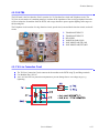
A fan is driven by a transistor and controlled by a signal from the CPU (FAN (SMPS CON2-23). When the signal
is high, the fan is activated by turning on the transistor, and is off when the system is in sleep mode. There are two
solenoids driven by the paper pick and MP signals. The drive time is 300ms. The diode protects the driving
transistor from the back EMP pulse which is generated when the solenoid is de-energized.
4.3.6.8 Motor Driving Circuit
The main motor drives the paper feed, developing unit, fuser, and exit assembly. The circuit is driven by software
which controls the acceleration, constant speed, and deceleration profiles. The Motor is driven using an A3977
driver IC.
4.3.6.9 Transfer
The charging voltage, developing voltage, and the transfer voltage are controlled by pulse width modulation
(PWM). Each output voltage is changeable according to the PWM duty cycle. The transfer voltage used when the
paper passes the transfer roller is decided by environment recognition. The resistance value of the transfer roller
changes due to the environment of the room or within the printer. This change in resistance in turn changes the
value of the voltage due to loading. This voltage is fed back into the printer through the A/D converter. Based on
the value fed back the PWM cycle is changed to maintain the required transfer voltage.
4.3.6.10 Fusing
The temperature of the heat roller's surface is detected according to the resistance value of the thermistor. The
thermistor resistance is measured using the A/D converter and thus the CPU can determine the temperature of the
heat roller. The AC power is controlled by comparing the target temperature to the value from the thermistor. If the
value from the thermistor is out of the controlled range while controlling the fusing process, an error is reported.
4-14
WorkCentre PE 120/120i