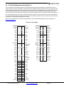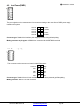
1
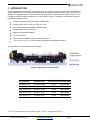
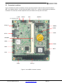
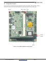
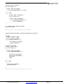
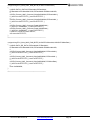
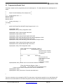
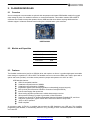
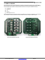
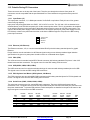
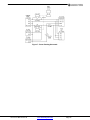
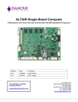
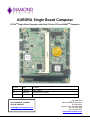
AURORA Single Board Computer
PC/104TM Single Board Computer with Atom Z-Series CPU and SUMITTM Expansion
Revision
Date
Comment
A5
1/16/2012
Minor updates
A6
2/24/2012
Added new Z510 models
FOR TECHNICAL SUPPORT
PLEASE CONTACT:
[email protected]
Copyright 2012
Diamond Systems Corporation
555 Ellis Street
Mountain View, CA 94043 USA
Tel 1-650-810-2500
Fax 1-650-810-2525
www.diamondsystems.com
CONTENTS
Important Safe-Handling Information .....................................................................................................................4
1. Introduction .......................................................................................................................................................5
1.1 Aurora SBC Features ....................................................................................................................................6
1.2 SUMIT Socket Resources .............................................................................................................................7
1.3 Software Compatibility ...................................................................................................................................7
1.4 Thermal Considerations and Heatspreader ..................................................................................................7
2. Functional Overview .........................................................................................................................................8
2.1 Block Diagram ...............................................................................................................................................8
2.2 Aurora Dimensions ........................................................................................................................................9
2.3 Connector Locations ................................................................................................................................... 10
2.3.1
Connector Summary .......................................................................................................................... 11
2.4 Configuration Jumpers ............................................................................................................................... 12
2.4.1
Configuration Jumper Summary ........................................................................................................ 13
3. Getting Started ............................................................................................................................................... 13
3.1 Introducing the Aurora Development Kit .................................................................................................... 14
3.1.1
Aurora Cable Kit ................................................................................................................................. 15
3.2 System Setup ............................................................................................................................................. 16
3.2.1
Keyboard and Mouse ......................................................................................................................... 16
3.2.2
USB Flashdisk Socket ....................................................................................................................... 16
3.2.3
Mass Storage Devices ....................................................................................................................... 16
3.2.4
Connecting Power .............................................................................................................................. 16
3.2.5
Display ............................................................................................................................................... 16
3.2.6
Installing Aurora in an Enclosure (optional) ....................................................................................... 16
3.3 Booting the System .................................................................................................................................... 17
3.3.1
BIOS Setup ........................................................................................................................................ 17
3.3.2
Operating System Drivers .................................................................................................................. 17
4. Interface Connector Details .......................................................................................................................... 18
4.1 SDVO Connector (SDVO1) ........................................................................................................................ 18
4.2 LCD Panel (LVDS Interface) Connector (LVDS1) ...................................................................................... 19
4.3 LCD Backlight Connector (INV1) ................................................................................................................ 19
4.4 SUMIT-A Expansion Bus (SUMITA1) ......................................................................................................... 20
4.5 Serial Ports (COM1, COM2) ....................................................................................................................... 21
4.6 PS/2 Keyboard/Mouse (KBMS1) ................................................................................................................ 22
4.7 External Battery (BAT1) .............................................................................................................................. 22
4.8 PC/104 (ISA) Expansion Bus (PC104_1) ................................................................................................... 23
4.9 Input Power (PWR1) ................................................................................................................................... 24
4.10 Ethernet (LAN1) .......................................................................................................................................... 24
4.11 USB 0-1 (USB1) ......................................................................................................................................... 25
4.12 USB 2-3 (USB2) ......................................................................................................................................... 25
4.13 USB Flashdisk (USB3) ............................................................................................................................... 26
4.14 SO-DIMM DRAM (SODIMM1) .................................................................................................................... 26
4.15 SATA (SATA1)............................................................................................................................................ 26
4.16 GPIO (GPIO_P1) ........................................................................................................................................ 27
5. Configuration Jumper Details ...................................................................................................................... 27
5.1 LCD Panel Power Select - 3.3V/5V (JVLCD1) ........................................................................................... 27
5.2 LCD Backlight Brightness Control (JBKC1) ............................................................................................... 28
5.3 LCD Backlight Power (JINV1) .................................................................................................................... 28
5.4 LCD Scan Direction (JLCD1) ...................................................................................................................... 28
5.5 CMOS RAM Reset / On-board Backup Battery Disconnect (JBAT1) ........................................................ 28
5.6 Serial Ports (JCOM3, JCOM4) ................................................................................................................... 29
6. BIOS ................................................................................................................................................................ 30
6.1 Entering the BIOS ....................................................................................................................................... 30
6.2 Restoring Default BIOS Settings ................................................................................................................ 30
6.3 Setting the Date and Time .......................................................................................................................... 30
6.4 ISA Bus IRQ Reservation ........................................................................................................................... 30
6.5 Boot Priority ................................................................................................................................................ 30
6.6 Chipset ........................................................................................................................................................ 30
6.7 Super I/O Configuration .............................................................................................................................. 31
6.8 Console Redirection ................................................................................................................................... 31
Aurora User Manual Rev A6
www.diamondsystems.com
Page 2
7.
Digital I/O Lines .............................................................................................................................................. 32
7.1 DIO Registers ............................................................................................................................................. 32
7.2 DIO Programming ....................................................................................................................................... 32
8. Watchdog Timer ............................................................................................................................................. 35
8.1 Registers ..................................................................................................................................................... 35
8.2 Programming Sample Code ....................................................................................................................... 36
9. FlashDisk Modules ........................................................................................................................................ 37
9.1 Overview ..................................................................................................................................................... 37
9.2 Models and Capacities ............................................................................................................................... 37
9.3 Features ...................................................................................................................................................... 37
9.4 Flashdisk Installation .................................................................................................................................. 38
10. Ruggedized RSODIMM™ SO-DIMM Modules.............................................................................................. 38
10.1 Models and Capacities ............................................................................................................................... 38
10.2 SO-DIMM Memory Installation ................................................................................................................... 38
11. Panel I/O Board .............................................................................................................................................. 39
11.1 Mechanical Drawing ................................................................................................................................... 40
11.2 Outside Facing I/O Connectors .................................................................................................................. 41
11.2.1 Input Power (J1) ................................................................................................................................. 41
11.2.2 Ethernet (J23 Ethernet)...................................................................................................................... 41
11.2.3 VGA (VGA) ........................................................................................................................................ 41
11.2.4 USB (USB1, USB2, USB3, USB4) .................................................................................................... 41
11.2.5 PS/2 Keyboard and Mouse (J25 Keyboard, J26 Mouse) .................................................................. 41
11.2.6 Serial Ports (COM1, COM2, COM3, COM4) ..................................................................................... 41
11.3 Power Routing ............................................................................................................................................ 42
12. Thermal Pad ................................................................................................................................................... 44
13. Specifications................................................................................................................................................. 45
Aurora User Manual Rev A6
www.diamondsystems.com
Page 3
IMPORTANT SAFE-HANDLING INFORMATION
WARNING: ESD-Sensitive Electronic Equipment!
Observe ESD-safe handling procedures when working with this product.
Always use this product in a properly grounded work area and wear
appropriate ESD-preventive clothing and/or accessories.
Always store this product in ESD-protective packaging when not in use.
Safe Handling Precautions
Aurora contains numerous I/O connectors that connect to sensitive electronic components. This creates many
opportunities for accidental damage during handling, installation and connection to other equipment. The list here
describes common causes of failure found on boards returned to Diamond Systems for repair. This information is
provided as a source of advice to help you prevent damaging your Diamond (or any vendor’s) embedded
computer boards.
ESD damage – This type of damage is almost impossible to detect, because there is no visual sign of failure or
damage. The symptom is that the board simply stops working, because some component becomes defective.
Usually the failure can be identified and the chip can be replaced.
To prevent ESD damage, always follow proper ESD-prevention practices when handling computer boards.
Damage during handling or storage – On some boards we have noticed physical damage from mishandling. A
common observation is that a screwdriver slipped while installing the board, causing a gouge in the PCB surface
and cutting signal traces or damaging components.
Another common observation is damaged board corners, indicating the board was dropped. This may or may not
cause damage to the circuitry, depending on what is near the corner. Most of our boards are designed with at
least 25 mils clearance between the board edge and any component pad, and ground / power planes are at least
20 mils from the edge to avoid possible shorting from this type of damage. However these design rules are not
sufficient to prevent damage in all situations.
A third cause of failure is when a metal screwdriver tip slips, or a screw drops onto the board while it is powered
on, causing a short between a power pin and a signal pin on a component. This can cause overvoltage / power
supply problems described below. To avoid this type of failure, only perform assembly operations when the
system is powered off.
Sometimes boards are stored in racks with slots that grip the edge of the board. This is a common practice for
board manufacturers. However our boards are generally very dense, and if the board has components very close
to the board edge, they can be damaged or even knocked off the board when the board tilts back in the rack.
Diamond recommends that all our boards be stored only in individual ESD-safe packaging. If multiple boards are
stored together, they should be contained in bins with dividers between boards. Do not pile boards on top of each
other or cram too many boards into a small location. This can cause damage to connector pins or fragile
components.
Power supply wired backwards – Our power supplies and boards are not designed to withstand a reverse
power supply connection. This will destroy each IC that is connected to the power supply. In this case the board
will most likely will be unrepairable and must be replaced. A chip destroyed by reverse power or by excessive
power will often have a visible hole on the top or show some deformation on the top surface due to vaporization
inside the package. Check twice before applying power!
Bent connector pins – This type of problem is often only a cosmetic issue and is easily fixed by bending the pins
back to their proper shape one at a time with needle-nose pliers. This situation can occur when pulling a ribbon
cable off of a pin header. Note: If the pins are bent too severely, bending them back can cause them to weaken
unacceptably or even break, and the connector must be replaced.
Aurora User Manual Rev A6
www.diamondsystems.com
Page 4
1. INTRODUCTION
Aurora is a high performance, highly integrated single board computer in the PC/104 form-factor incorporating a
wealth of standard PC-style I/O plus on-board digital I/O. It accepts both SUMIT-A and PC/104 (ISA) add-on I/O
modules. An integrated, bottom-mounted heatspreader dissipates heat efficiently to the system enclosure. This
configuration leaves the SBC’s top side free for easy access to memory, on-board I/O, and expansion sockets.
Key feature highlights include:
Compact, low-power, high-performance, stackable SBC
Intel Atom Z530 CPU at 1.6GHz or Z510 at 1.1GHz
Up to 2GB ruggedized RSODIMM™ DDR2 SDRAM
Comprehensive set of I/O interfaces
Optional on-board USB flashdisk
PC/104 form-factor
PC/104 (ISA) and SUMIT-A (PCIe) stackable expansion
-40°C to +80°C (-40°F to +176°F) operating temperature at heatspreader surface
Aurora’s features are summarized on the next page.
Figure 1: Edge View of the Aurora SBC
Aurora Models
Processor Type
Processor Clock SO-DIMM RAM
AUR-Z530-16-0G
Intel Atom Z530P
1.6GHz
0GB SDRAM
AUR-Z530-16-1G
Intel Atom Z530P
1.6GHz
1GB SDRAM
AUR-Z530-16-2G
Intel Atom Z530P
1.6GHz
2GB SDRAM
AUR-Z510-11-0G
Intel Atom Z510
1.1GHz
0GB SDRAM
AUR-Z510-11-1G
Intel Atom Z510
1.1GHz
1GB SDRAM
PC/104™ is a trademark of the PC/104 Embedded Consortium. SUMIT™ is a trademark of the SFF-SIG.
Aurora User Manual Rev A6
www.diamondsystems.com
Page 5
All other trademarks are the property of their respective owners.
1.1
Aurora SBC Features
Aurora is a rugged, single board computer (SBC) based on the 1.6GHz Intel Atom Z-Series CPU and conforming
to the compact, PC/104 form-factor (90 x 96mm). It provides multiple expansion options by means of PC/104
(ISA) modules and SUMIT-A modules.
Functions
Processor: Intel Atom Z530P at 1.6GHz or Z510 at 1.1GHz
Cooling: Heatspreader, fanless
Memory: Up to 2GB ruggedized RSODIMM™ DDR2 DRAM
Display options:
- LVDS flat panel interface
Diamond supports Sharp LQ121S1LG41 and LQ121S1LG42 flat panels
- SDVO (optional VGA adapter accessory available)
LVDS backlight power: +5V or +12V jumper selectable
USB ports: 4 USB 2.0
Serial ports: 2 RS-232/422/485, 2 RS-232
Networking: 1 Gigabit Ethernet – Intel 82574IT
Mass storage:
- 1 SATA port
- Support for up to 8GB USB flashdisk
Keyboard/Mouse: PS/2 with BIOS support for USB
Digital I/O: 8 digital I/O lines
Watchdog Timer: Yes
PCI Express: 1 PCIe x1 lane to SUMIT-A bus
Expansion buses:
- SUMIT-A stackable
- PC/104 (ISA) stackable
Input power: 5V ±5%
Power consumption: 5.4W
Operating temp.: -40°C to +80°C (-40°F to +176°F) at heatspreader surface
Dimensions: 3.55" x 3.775" x 0.9” (90mm x 96mm x 23mm)
Weight: 7.5oz / 212g
RoHS Compliant
Operating System Support
Linux 2.6
Windows XP and XPe
Aurora User Manual Rev A6
www.diamondsystems.com
Page 6
1.2
SUMIT Socket Resources
Aurora’s SUMIT-A expansion socket provides the host interface resource support indicated in the table below. For
further details on the SUMIT expansion standard, visit SFF-SIG.org/sumit.html.
1.3
Software Compatibility
Aurora is compatible with Linux, Windows XP, and Windows Embedded Standard. All necessary drivers for these
operating systems are provided with the product.
1.4
Thermal Considerations and Heatspreader
o
o
All models of Aurora are specified for a -40 C to +80 C operating range, the temperature being measured at the
outside surface of the heatspreader. Diamond provides a heatspreader attached to the Aurora single board
computer as a conductive cooled thermal layer. However, this heatspreader by itself does not constitute the
complete thermal solution necessary for any specific implementation, but provides a common interface between
the single board computer and the customer’s implementation-specific thermal solution.
o
The outside surface of the Aurora heatspreader must be kept at a temperature not to exceed +80 C. If your
environment causes the temperature on the outside surface of the heatspreader to exceed this temperature, you
are responsible for removing the additional heat from the system through either an additional passive thermal
solution or fan solution.
Aurora’s integrated heatspreader makes thermal contact with the heat generating components and provides a flat
surface on the bottom of the assembly for mating to the system enclosure. This technique facilitates efficient
removal of heat from the SBC without the need for a fan. Four mounting holes on the bottom of the conduction
cooled heatspreader are provided to mount Aurora in an enclosure or to a bulkhead. These mounting holes are
#6-32 threaded holes on 2.8" centers.
Aurora User Manual Rev A6
www.diamondsystems.com
Page 7
2. FUNCTIONAL OVERVIEW
2.1
Block Diagram
Figure 2 shows Aurora’s functional blocks.
Figure 2: Aurora Functional Block Diagram
Aurora User Manual Rev A6
www.diamondsystems.com
Page 8
2.2
Aurora Dimensions
Figure 3 shows the overall dimensions of the Aurora SBC.
Figure 3: Aurora Dimensions
Aurora User Manual Rev A6
www.diamondsystems.com
Page 9
2.3
Connector Locations
Figure 4 illustrates the position of interface and bus connectors jumpers located on the top side of the Aurora
SBC. Two expansion buses – PC/104 (ISA) and SUMIT-A (PCIe, etc.) – enable on-board stacking of additional
I/O boards. The connectors for both expansion buses are located on the top side of the board.
LVDS1
(on underside of board)
SDVO1
INV1
SUMITA1
GPIO_P1
KBMS1
USB3
COM1
SATA1
SODIMM1
USB2
COM2
USB1
BAT1
LAN1
PWR1
PC104_1
Figure 4: Aurora SBC Connector Locations
Aurora User Manual Rev A6
www.diamondsystems.com
Page 10
2.3.1
Connector Summary
The following table summarizes the functions of Aurora’s interface, utility, and power connectors. Signal functions
relating to all of Aurora’s interface connectors are discussed in greater detail in Section 4 of this document.
Diamond offers an optional Aurora Cable Kit (number C-AUR-KIT), which provides mating cable assemblies for
most of Aurora’s I/O interface connectors.
Connector Function
Serial Digital Video Out
LCD Backlight
SUMIT-A Bus
PS/2 Keyboard Mouse
On-board USB flashdisk
Serial Ports
External Battery Input
PC/104 Expansion Bus
Input Power
Ethernet
USB Ports
SO-DIMM DRAM
SATA
GPIO
LCD (LVDS) Panel
Aurora User Manual Rev A6
Silkscreen Label
Connector Type
SDVO1
INV1
SUMITA1
KBMS1
USB3
COM1 (for Port1 & Port2)
COM2 (for Port3 & Port4)
20-pin vertical connector
6-pin header
52-pin female socket
10-pin dual-row header
10-pin dual-row header
BAT1
PC104_1
PWR1
LAN1
USB1, USB2
SODIMM1
SATA1
GPIO_P1
LVDS1
2-pin plug
104-pin quad-row socket
12-pin dual-row header
10-pin dual-row header
10-pin dual-row header
SO-DIMM memory socket
7-pin standard SATA interface
connector
10-pin dual-row header
20-pin single-row header
www.diamondsystems.com
20-pin dual-row header
Page 11
2.4
Configuration Jumpers
Figure 5 shows the configuration jumper groups that are located on the topside of the Aurora SBC. Refer to
Section 5 for details on the functions and configuration options associated with each jumper group.
JVLCD1
JBKC1 JINV1 JLCD1
JCOM3
JCOM4
JBAT1
Figure 5: Aurora SBC Configuration Jumper Groups
Aurora User Manual Rev A6
www.diamondsystems.com
Page 12
2.4.1
Configuration Jumper Summary
Aurora’s configuration jumpers are listed below. Refer to Section 5 of this document for details regarding the
configuration of these jumper groups.
Jumper Group Function
Silkscreen Label
LCD Panel Power Select (3.3V/5V)
JVLCD1
Array Size
1x3
LCD Backlight Brightness Control
JBKC1
2x2
LCD Backlight Power ( 5V/12V)
JINV1
1x3
LCD Scan Direction
JLCD1
2x2
Serial Ports 3 and 4 RS-422/485 configuration
JCOM3, JCOM4
2x5
CMOS RAM Reset / On-Board Backup Battery Disconnect JBAT1
1x3
3. GETTING STARTED
First-time Aurora users normally receive the product as part of Diamond’s Aurora Development Kit, which
provides everything needed to ensure rapid application development. This section of the Aurora User Manual
covers basic hardware setup, power connection, system boot-up, and initial software configuration. After Aurora is
up and running, refer to the later sections of this manual for the detailed hardware and software reference
information needed to adapt the product to specific applications.
Important Safe-Handling Information
WARNING: ESD-Sensitive Electronic Equipment!
Observe ESD-safe handling procedures when working
with this product.
Always use this product in a properly grounded work area
and wear appropriate ESD-preventive clothing and/or
accessories.
Always store this product in ESD-protective packaging
when not in use.
Please refer to page 4 of this manual (“Important Safe-Handling Information”) for further
details.
Aurora User Manual Rev A6
www.diamondsystems.com
Page 13
3.1
Introducing the Aurora Development Kit
The Aurora Development Kit (DK-AUR-01) provides everything required for Aurora-based rapid application
development. The table below lists the boards, cables, and other items included.
Item
Diamond P/N
Description
1
AUR-Z530-16-1G
Aurora PC/104 SBC, 1.6GHz Atom Z530, 1GB SDRAM
2
ACC-VGA-03
VGA Accessory Kit for Aurora
3
8890300
4GB USB flashdisk with Linux pre-loaded
4
PS-5V-04
AC Power Adapter, +5VDC
5
7460610
Quickstart Guide for Aurora SBC
6
C-AUR-KIT
Aurora Cable Kit for on-board I/O
7
DOC-PKG
Documentation Package
8
6981037
PS-5V-04 to Aurora power cable
Aurora User Manual Rev A6
www.diamondsystems.com
Page 14
3.1.1
Aurora Cable Kit
The Aurora Cable Kit (number C-AUR-KIT) provides convenient access to most of Aurora’s I/O features. The kit’s
cable assemblies are shown in the photo below, and identified in the table that follows.
Note: On each interface cable, the end of the cable connector that has a red wire going to it
should be oriented toward the end of the board connector that is labeled “pin 1” (typically the pin
with a square pad on the PCB).
Qty
1
1
Ethernet cable, 2x5 2mm
6981080
LAN1
2
2
Dual Serial port cable, 2x20 2mm
6981081
COM1, COM2
3
2
Dual USB cable, 2x5 2mm
6981082
USB1, USB2
4
1
PS/2 Keyboard Mouse, 2x5 2mm
6981301
KBMS1
5
1
Digital I/O cable, 2x5 2mm
6981302
GPIO_P1
6
1
Power input cable, 2x6 2mm
6981303
PWR1
Aurora User Manual Rev A6
Description
Diamond P/N
Connects to…
Item
www.diamondsystems.com
Page 15
3.2
System Setup
This section outlines a simple process for preparing Aurora for first-time operation using the Aurora Development
Kit. Additional details regarding Aurora’s interface functions and connections may be found in Section 4 of this
document (“Interface Connector Details”).
3.2.1
Keyboard and Mouse
Aurora supports operation using PS/2-based keyboard and mouse devices. Plug the keyboard and mouse cable,
6981301, from the Aurora Cable Kit into the connector KBMS1 on Aurora. Then plug the keyboard and mouse
into the mating connectors on the Aurora interface cables.
3.2.2
USB Flashdisk Socket
Aurora provides a location for on-board installation of an optional USB flashdisk on connector USB3. Plug the
USB flashdisk module, 8890300, in the Development Kit into connector USB3 on Aurora. Remove the screw from
the mounting stand-off before installing the flashdisk. Secure the flashdisk to Aurora with the screw once the
flashdisk is installed.
3.2.3
Mass Storage Devices
If desired, connect SATA hard drives to Aurora by connecting a USB cable, part number 6981082, to connector
USB1 and then to the SATA drive. Aurora can operate with a combination of SATA and CD-ROM drives, and can
boot from either of them.
Caution! Be sure the PS-5V-01 AC power adapter is disconnected from
its AC power source prior to performing the following step…
3.2.4
Connecting Power
Connect cable 6981037 to the PS-5V-01 AC power adapter. Connect the other end of the 6981037 cable to
connector PWR1 on the Aurora SBC.
3.2.5
Display
Aurora provides interfaces for both LVDS flat panel displays and SDVO output. VGA CRTs can also be used via
an external SDVO to VGA converter. This quick-start process assumes you are using the external VGA converter
(number ACC-VGA-03) supplied with the development kit.
Install the I/O board provided in the ACC-VGA-03 kit on top of Aurora, aligning the PC/104 and SUMIT-A
connectors. Connect the VGA cable supplied in the ACC-VGA-03 between the VGA connector on the I/O board
and a VGA-compatible display.
3.2.6
Installing Aurora in an Enclosure (optional)
Install the Aurora single board computer in an enclosure that has an appropriate mounting-hole pattern (2.8”
square).
Aurora’s heatspreader has four #6-32 threaded holes on 2.8” centers for mounting. Select four #6-32 threaded
screws of the proper length and head type to work with your enclosure. Allow a minimum of 0.25” and maximum
of 0.40” screw length for insertion into Aurora’s heatspreader. The total screw length will depend on the thickness
of your enclosure wall.
Aurora User Manual Rev A6
www.diamondsystems.com
Page 16
3.3
Booting the System
Power-up the VGA video monitor. Then plug the PS-5V-01 AC power adapter to an AC outlet. Aurora should
begin its boot-up sequence immediately, as evidenced by BIOS messages on the connected VGA display. You
can run the BIOS Setup utility and proceed to install an operating system on the boot drive just as you would on a
normal desktop PC.
3.3.1
BIOS Setup
Aurora’s BIOS provides a wide range of configuration options. When you power up Aurora for the first time, you
should immediately enter the BIOS “Setup” utility in order to adjust BIOS settings to match your system’s
peripheral devices and other requirements, and to configure various other hardware and software parameters.
Options configurable via Setup typically include:
Number and type of mass storage devices
Boot device priority
Video display type and resolution
IDA, SATA, serial, and parallel interface modes and protocols
PCI and PnP configuration
Power management setup
Automatic power-up after LAN connection, RTC alarm, power resumption, etc.
System monitoring and security functions
3.3.2
Operating System Drivers
Aurora will boot and run a Linux 2.6 operating system from the USB flashdisk. Aurora should now be fully
operational.
If you desire to run a different operating system, depending on the operating system to be installed, it may be
necessary to install software drivers for on-board interface controllers. Drivers for Windows XP, XPe, and Linux
2.6, if required, are included on the Software and Documentation CD that is included in the Aurora Development
Kit. This software is also available for download from the Aurora page at Diamond’s website,
www.diamondsystems.com/products/aurora.
Aurora User Manual Rev A6
www.diamondsystems.com
Page 17
4. INTERFACE CONNECTOR DETAILS
This section describes the functions associated with the Aurora baseboard’s SUMIT-A bus, PCI-104 bus
expansion stack, utility, I/O interfaces, and power connectors in greater detail. Section 3.1.1 contains a list of
ready-to-use interface cables included in Diamond’s Aurora Cable Kit.
4.1
SDVO Connector (SDVO1)
The SDVO connector provides differential pair video output signals.
An optional SDVO to VGA converter accessory, number ACC-VGA-03, interfaces with this connector and
provides signals for directly driving VGA-interfaced CRTs and LCDs. The VGA converter I/O board provides a
standard DE-15 VGA connector.
1
SDVO_B_BLUE#
2
BUF_PLT_RST#
3
SDVO_B_BLUE
4
Ground
5
Ground
6
SDVO_B_GREEN#
7
SDVO_CTRLCLK
8
SDVO_B_GREEN
9
SDVO_CTRLDATA
10
Ground
11
Ground
12
SDVO_B_CLK_N
13
+3.3V
14
SDVO_B_CLK_P
15
+3.3V
16
Ground
17
+5V
18
SDVO_B_RED#
19
+5V
20
SDVO_B_RED
PCB connector: SAMTEC ERM8-010-08.0-L-DV 20 pin 0,800 mm pin spacing
Mating connector: SAMTEC ERF8-010-07.0-L-DV
Aurora User Manual Rev A6
www.diamondsystems.com
Page 18
4.2
LCD Panel (LVDS Interface) Connector (LVDS1)
This connector is mounted on the bottom side of Aurora, directly below the SDVO connector, SDVO1. It provides
connection to an LVDS LCD display. The LCD panel power is jumpeRSelectable for 3.3V (default) or 5V.
1
Ground / D3+, depending on video chip
2
Ground / D3-, depending on video chip
3
Scan Direction (High = Reverse Scan, Low/open = Normal Scan)
4
Frame Rate Control (High = On, Low/open = Off)
5
Signal Ground
6
Pixel Clock +
7
Pixel Clock -
8
Signal Ground
9
D2+
10
D2-
11
Signal Ground
12
D1+
13
D1-
14
Signal Ground
15
D0+
16
D0-
17
Power Ground
18
Power Ground
19
Vcc 3.3V / 5V (jumper configured)
20
Vcc 3.3V / 5V (jumper configured)
PCB connector: JAE part no. FI-SE20P-HFE or equivalent
Cable-mount socket: JAE part no. FI-SE20S-2-L or equivalent
4.3
LCD Backlight Connector (INV1)
This connector provides the backlight power and control for the optional LCD panel. The brightness control for
the LCD backlight can be found on jumper JBKC1. Note: If needed, +12V must be provided on the input power
connector.
1
Power +5V/+12V, jumper selectable
2
Power (same as pin 1)
3
Ground
4
Ground
5
Enable (GPIO output), 0 = off, open circuit = on
6
Brightness, 0-5VDC variable; 0V = max, 5V = min
PCB connector: Molex 53047-0610 or equivalent
Mating connector and pin types: Socket: Molex 51021-0600 or equivalent
Terminals: Molex 50058 / 50079 series or equivalent
Aurora User Manual Rev A6
www.diamondsystems.com
Page 19
4.4
SUMIT-A Expansion Bus (SUMITA1)
The SUMIT-A stackable bus is a 52-pin surface mount connector located on the expansion side of the board.
Aurora implements the following SUMIT bus functions:
1 PCIe x1 lane
3 USB 2.0 channels
LPC bus
SMBus
SPI, if a chip select is available from the embedded controller IC
The standard signal assignments of the SUMIT-A connector appear in below. Note: For more information on the
SUMIT specification, visit the SFF-SIG website at http://www.sff-sig.org.
Aurora User Manual Rev A6
+5VSB
1
2
+12V
3.3V
3
4
SMB/I2C_DATA
3.3V
5
6
SMB/I2C_CLK
EXPCD_REQ#
7
8
SMB/I2C_ALERT#
EXPCD_PRSNT#
9
10
SPI/uWire_DO
USB_OC#
11
12
SPI/uWire_DI
RSVD
13
14
SPI/uWire_CLK
+5V
15
16
SPI/uWire_CS0#
USB3+
17
18
SPI/uWire_CS1#
USB3-
19
20
Reserved
+5V
21
22
LPC_DRQ
USB2+
23
24
LPC_AD0
USB2-
25
26
LPC_AD1
+5V
27
28
LPC_AD2
USB1+
29
30
LPC_AD3
USB1-
31
32
LPC_FRAME#
+5V
33
34
SERIRQ#
USB0+
35
36
LPC_PRSNT#/GND
USB0-
37
38
CLK_33MHz
Ground
39
40
Ground
A_PETp0
41
42
A_PERp0
A_PETn0
43
44
A_PERn0
Ground
45
46
APRSNT#/GND
PERST#
47
48
A_CLKp
WAKE#
49
50
A_CLKn
+5V
51
52
Ground
www.diamondsystems.com
Page 20
4.5
Serial Ports (COM1, COM2)
These connectors provide access to the board's four serial ports. COM1 provides access to Port1 and Port2.
COM2 provides access to Port3 and Port4.
Ports 1 and 2 are fixed for RS-232 only, while ports 3 and 4 may be jumper-configured for RS-232, RS-422, or
RS-485 protocols. The connector pinout changes depending on the selected protocol. Aurora can be customordered preconfigured for a selected protocol; it is also possible to order a fixed configuration with soldered-on
zero ohm resistors, so no jumpers are used.
RS-232 Configuration
Port 1
Port 2
Port 3
Port 4
RS-422 Configuration
RS-485 Configuration
DCD 1
1
2
DSR 1
1
2
1
2
RXD 1
3
4
RTS 1
3
4
3
4
TXD 1
5
6
CTS 1
5
6
5
6
DTR 1
7
8
RI 1
7
8
7
8
Ground
9
10
NC
9
10
9
10
DCD 2
11
12
DSR 2
11
12
11
12
RXD 2
13
14
RTS 2
13
14
13
14
TXD 2
15
16
CTS 2
15
16
15
16
DTR 2
17
18
RI 2
17
18
17
18
Ground
19
20
NC
19
20
19
20
DCD 3
1
22
DSR 3
NC
21
22
RXD- 3
NC
21
22
NC
RXD 3
3
24
RTS 3
RXD+ 3
23
24
TXD- 3
NC
23
24
TXD/RXD- 3
TXD 3
5
26
CTS 3
TXD+ 3
25
26
NC
TXD/RXD+ 3
25
26
NC
DTR 3
7
28
RI 3
NC
27
28
NC
NC
27
28
NC
Ground
9
30
NC
Ground
29
30
NC
Ground
29
30
NC
DCD 4
11
32
DSR 4
NC
31
32
RXD- 4
NC
31
32
NC
RXD 4
13
34
RTS 4
RXD+ 4
33
34
TXD- 4
NC
33
34
TXD/RXD- 4
TXD 4
15
36
CTS 4
TXD+ 4
35
36
NC
TXD/RXD+ 4
35
36
NC
DTR 4
17
38
RI 4
NC
37
38
NC
NC
37
38
NC
Ground
19
40
NC
Ground
39
40
NC
Ground
39
40
NC
Connector type: Standard 2mm dual row straight pin header with 4mm posts and gold flash plating
Mating connector and pin types: Molex 51110-2050 connector with Molex 50394-8100 terminals
Aurora User Manual Rev A6
www.diamondsystems.com
Page 21
4.6
PS/2 Keyboard/Mouse (KBMS1)
This connector provides the standard PS/2 keyboard and mouse signals.
+5V
1
2
No connection
KB Data
3
4
MS Data
KB Clk
5
6
MS Clk
KB Ground
7
8
Key
KB Ground
9
10
RESET BTN#
Connector type: Standard 2mm dual row straight pin header with 4mm posts and gold flash plating
Mating connector and pin types: A2005H02 2x5P connector with A2005T0P-00 terminals
4.7
External Battery (BAT1)
Aurora has provision for an external battery connection via BAT1, a two-pin connector.
A connector and jumper are provided to disable the on-board battery and enable use of an external battery
instead. The external battery voltage requirement is 3.3V +/-10%. The jumper also clears the CMOS RAM when it
is removed and no external battery is connected.
1
Ground
2
Battery+
Connector type: Shrouded 2mm header with key notch
Mating connector and pin types: Molex 51021-0200 connector with Molex 50079-8000 contacts
Aurora User Manual Rev A6
www.diamondsystems.com
Page 22
4.8
PC/104 (ISA) Expansion Bus (PC104_1)
The PC/104 bus is essentially identical to the ISA Bus except for the physical design. It specifies two pin and
socket connectors for the bus signals. A 64-pin header incorporates the 62-pin 8-bit bus connector signals, and a
40-pin header incorporates the 36-pin 16-bit bus connector signals. The additional pins on the PC/104 connectors
are used as ground or key pins. The female sockets on the top of the board enable stacking another PC/104
board on top of the board, while the male pins on the bottom enable the board to plug into another board below it.
In the pinout figures below, the tops correspond to the left edge of the connector when the board is viewed from
the primary side (side with the female end of the PC/104 connector) and the board is oriented so that the PC/104
connectors are along the bottom edge of the board.
Note: For more information on the PC/104 specification, visit the PC/104 Embedded Consortium website, at
http://www.pc104.org.
View from Top of Board
PC/104 8-bit bus connector
IOCHK-
A1
B1
SD7
A2
B2
SD6
A3
B3
SD5
A4
B4
SD4
A5
B5
SD3
A6
B6
SD2
A7
B7
SD1
A8
B8
SD0
A9
IOCHRDY
PC/104 16-bit bus connector
Ground
C0
D0
Ground
SBHE-
C1
D1
MEMCS16-
LA23
C2
D2
IOCS16-
LA22
C3
D3
IRQ10
LA21
C4
D4
IRQ11
LA20
C5
D5
IRQ12
-12V
LA19
C6
D6
IRQ15
OWS-
LA18
C7
D7
IRQ14
B9
+12V
LA17
C8
D8
DACK0-
A10
B10
KEY
MEMR-
C9
D9
DRQ0
AEN
A11
B11
SMEMW-W
MEMW-
C10
D10
DACK5-
SA19
A12
B12
SMEMR-
SD8
C11
D11
DRQ5
SA18
A13
B13
IOW-
SD9
C12
D12
DACK6-
SA17
A14
B14
IOR-
SD10
C13
D13
DRQ6
SA16
A15
B15
DACK3-
SD11
C14
D14
DACK7-
SA15
A16
B16
DRQ3
SD12
C15
D15
DRQ7
SA14
A17
B17
DACK1-
SD13
C16
D16
+5V
SA13
A18
B18
DRQ1
SD14
C17
D17
MASTER-
SA12
A19
B19
SD15
C18
D18
Ground
SA11
A20
B20
SYSCLK
KEY
C19
D19
Ground
SA10
A21
B21
IRQ7
SA9
A22
B22
IRQ6
SA8
A23
B23
IRQ5
SA7
A24
B24
IRQ4
SA6
A25
B25
IRQ3
SA5
A26
B26
DACK2-
SA4
A27
B27
TC
SA3
A28
B28
BALE
SA2
A29
B29
+5V
SA1
A30
B30
OSC
SA0
A31
B31
Ground
Ground
A32
B32
Ground
Aurora User Manual Rev A6
Ground
RESET
+5V
IRQ9
-5V
DRQ2
REFRESH-
www.diamondsystems.com
Page 23
4.9
Input Power (PWR1)
The power signals on this connector come from a connector leading to the output from a DC/DC power supply
installed in the system.
Ground
Ground
Ground
Ground
Key
Ground
1
3
5
7
9
11
2
4
6
8
10
12
+5VDC
+12VDC
+5VDC
+5VDC
Ext Bat1
Connector type: Standard dual row 2mm pitch straight pin header with gold flash plating
Mating connector and pin types: A2005H02 2x6P connector with A2005T0B-00 terminals
4.10 Ethernet (LAN1)
This connector provides access to the board's gigabit Ethernet port.
Common
1
2
Key
DA+
3
4
DA-
DB+
5
6
DB-
DC+
7
8
DC-
DD+
9
10
DD-
Connector type: Standard 2mm dual row vertical pin header with 4mm posts and gold flash plating
Mating connector: Molex 51110-1050 connector
Aurora User Manual Rev A6
www.diamondsystems.com
Page 24
4.11 USB 0-1 (USB1)
This connector provides access to two of the board's four USB 2.0 ports, USB0 and USB1. The shield pin is tied
to system ground.
Key
1
2
Shield
USB1 Pwr-
3
4
USB0 Pwr-
USB1 Data+
5
6
USB0 Data+
USB1 Data-
7
8
USB0 Data-
USB1 Pwr+
9
10
USB0 Pwr+
Connector type: Standard 2mm vertical pin header with 4mm posts and gold flash plating
Mating connector and pin types: Molex 51110-1050 connector with Molex 50394-8100 terminals
4.12 USB 2-3 (USB2)
This connector provides access to two of the board's four USB 2.0 ports, USB2 and USB3. The shield pin is tied
to system ground.
Key
1
2
Shield
USB3 Pwr-
3
4
USB2 Pwr-
USB3 Data+
5
6
USB2 Data+
USB3 Data-
7
8
USB2 Data-
USB3 Pwr+
9
10
USB2 Pwr+
Connector type: Standard 2mm dual row vertical pin header with 4mm posts and gold flash plating
Mating connector and pin types: Molex 51110-1050 connector with Molex 50394-8100 terminals
Aurora User Manual Rev A6
www.diamondsystems.com
Page 25
4.13 USB Flashdisk (USB3)
This connector is used for the USB on-board flashdisk interface. This is a dedicated USB port. An accessory
cable, C-FDU-01, is available that connects the USB flashdisk to any USB port. This simplifies programming the
flashdisk, or downloading data from it, by providing a direct connection between the flashdisk and a host PC.
USB7 Pwr+
1
2
NC
USB7 Data-
3
4
NC
USB7 Data+
5
6
NC
USB7 Pwr-
7
8
NC
Key
9
10
NC
Connector type: Standard 2mm dual straight pin header with 4mm posts and gold flash plating
4.14 SO-DIMM DRAM (SODIMM1)
A standard SO-DIMM DDR2 DRAM connector is provided for system memory.
4.15 SATA (SATA1)
The SATA connector is an industry-standard connector.
1
Ground
2
Transmit+
3
Transmit-
4
Ground
5
Receive-
6
Receive+
7
Ground
Connector type: Industry-standard horizontal SATA connector, SATA 7P female with lock
Aurora User Manual Rev A6
www.diamondsystems.com
Page 26
4.16 GPIO (GPIO_P1)
The GPIO connector is a standard 2mm dual row vertical pin header with 4mm posts and gold flash plating.
GPIO0
1
2
GPIO1
GPIO2
3
4
GPIO3
GPIO4
5
6
GPIO5
GPIO6
7
8
GPIO7
Ext. Reset Input
9
10
Ground
Connector type: Standard 2mm dual row vertical pin header with 4mm posts and gold flash plating
Mating connector and pin types: A2005H02 2x5P connector with A2005T0B-00 terminals
5. CONFIGURATION JUMPER DETAILS
This section explains the use of several jumper options on the Aurora Baseboard.
5.1
Jumper Group Function
Silkscreen Label
Array Size
LCD Panel Power Select (3.3V/5V)
JVLCD1
1x3
LCD Backlight Brightness Control
JBKC1
2x2
LCD Backlight Power ( 5V/12V)
JINV1
1x3
LCD Scan Direction
JLCD1
2x2
Serial Ports 3 and 4 RS-422/485 configuration
JCOM3, JCOM4
2x5
CMOS RAM Reset / On-Board Backup Battery Disconnect
JBAT1
1x3
LCD Panel Power Select - 3.3V/5V (JVLCD1)
This jumper group must be configured according to input voltage required by the type of LCD panel that will be
attached to Aurora’s LCD panel interface connector.
Aurora User Manual Rev A6
Setting
LCD Panel Voltage
Short 1-2
+5V
Short 2-3
+3.3V (default)
www.diamondsystems.com
Page 27
5.2
LCD Backlight Brightness Control (JBKC1)
This jumper group controls the LCD brightness selection.
5.3
Setting
Mode
Short 1-2
Brightness set by chipset
Backlight control
Short 3-4
Brightness set by Display Data
Channel PWM (default)
LCD Backlight Power (JINV1)
This jumper group controls the LCD backlight inverter DC power selection.
5.4
Setting
LCD Panel Voltage
Short 1-2
+5V (default)
Short 2-3
+12V
LCD Scan Direction (JLCD1)
This jumper group controls the LCD panel scan direction and frame rate control.
5.5
Setting
Mode
Short 1-2
Reverse Scan Direction
Short 3-4
Forward Scan Direction (default)
CMOS RAM Reset / On-board Backup Battery Disconnect (JBAT1)
This jumper group controls the external battery backup enable settings.
Aurora User Manual Rev A6
Setting
Mode
Short 1-2
Backup battery
connected (default)
Short 2-3
Clear CMOS
www.diamondsystems.com
Page 28
5.6
Serial Ports (JCOM3, JCOM4)
Following is the Aurora multi-protocol jumper selection for COM3 and COM4. Port COM3 is associated with
jumper block JCOM3, and COM4 is associated with JCOM4.
Aurora User Manual Rev A6
www.diamondsystems.com
Page 29
6. BIOS
Aurora’s BIOS provides access to many valuable features. These instructions show how to enter the BIOS, set up
features, and restore the BIOS to its default settings.
6.1
Entering the BIOS
The BIOS may be entered during startup by pressing the DEL key on an attached keyboard or pressing F4 if
using console redirection. Press the key repeatedly right after power-on or reset until the BIOS screen appears.
After a certain amount of time during startup, the BIOS will ignore the DEL or F4 key. If you wait too long and the
system does not respond, simply reset the system (or power down) and try again.
6.2
Restoring Default BIOS Settings
In order to load the default BIOS settings, turn off the system and install a jumper on pins 2-3 of jumper block
JBAT1, located on the bottom right corner of the board. This will clear CMOS and reset the BIOS to the default
settings. After three seconds put the jumper back to position 1-2 and turn the system on.
On the first screen after booting up, the user will be asked to press F1 to run SETUP, or F2 to load the defaults.
6.3
Setting the Date and Time
The date and time are set in the BIOS. Select Main menu, then enter the date and time at the bottom of the
screen. This screen also displays the CPU speed and memory capacity of the board.
6.4
ISA Bus IRQ Reservation
An ISA bus IRQ must be reserved in the BIOS in order to be used by the on-board ISA bus circuits or an installed
PC/104 module. To reserve an IRQ, go to the PCIPnP menu and scroll down to the IRQ list at the bottom. The
default settings are IRQ15 reserved with the remaining IRQs available.
6.5
Boot Priority
To select Boot devices and set their priority, go to the Boot -> Boot device priority menu and select the first boot
device from the list.
Upon clicking on the first boot device, a window with the available devices will open. The user can select any of
the devices as the first boot device.
The devices can be a SATA HDD, a network drive, or a USB device.
The USB device present in this list is the first Drive defined in the “USB Drives” Menu.
Here are the steps to select a USB drive to boot from:
st
1. Boot-> USB Drives -> 1 Drive -> ( select a USB device from the list)
st
2. Boot->Boot Device Priority-> 1 Boot device ( select the USB device which has been defines in line 1)
In this way, the system will try to boot from the USB device. The same procedure applies for other boot devices
(2nd, 3rd,…).
6.6
Chipset
The chipset menu is provided to define and change the North / South Bridge options such as Graphic Adapter
Modes, flat panel type (default is 800x600), and enable/disable on-board PCI3 line and Ethernet adapter.
By default, both PCIe and LAN controllers are enabled. This can be changed in the South Bridge menu.
Aurora User Manual Rev A6
www.diamondsystems.com
Page 30
6.7
Super I/O Configuration
This is to set the address/IRQ of the four serial ports. COM3 and COM4 are capable of RS-232/422/485
protocols; whereas COM1 and COM2 can only be set to RS-232.
6.8
Console Redirection
In the advanced menu, the user can select any of the serial ports for console redirection with different speeds
ranging from 115200bps to 9600bps as follows.
Advanced - Remote Access Configuration - Disabled (Default)
When set to Enabled, the console re-direction is activated on COM1 by default at 115200,n,8,1 communication
settings. The remote access configuration can be enabled on any of the four COM ports. Baud rates supported
are 115200 (default when enabled), 57600, 38400, 19200 and 9600.
When set to Enabled, the BIOS can be accessed by pressing F4 on the remote keyboard. BBS POPUP can be
accessed by pressing F3 on that remote keyboard.
Aurora User Manual Rev A6
www.diamondsystems.com
Page 31
7. DIGITAL I/O LINES
Aurora has eight digital I/O lines found on connector GPIO_P1. This connector has one pin for each line plus an
External Reset Input and Ground line. Please note that the digital I/O lines on Aurora are not 5V tolerant.
7.1
DIO Registers
Aurora’s digital I/O lines are associated with a set of registers as shown in the following table.
7.2
Register
EC RAM
Read/Write
Description
DIO_P0_DIR
1658h
R/W
DIO_P1_DIR
1659h
R/W
Output: 0x40
DIO_P2_DIR
165Ah
R/W
Input:
DIO_P3_DIR
165Bh
R/W
DIO_P4_DIR
165Ch
R/W
DIO_P5_DIR
1614h
R/W
DIO_P6_DIR
1615h
R/W
DIO_P7_DIR
1616h
R/W
DIO_P0_LVL
160Ah[bit0]
R/W
DIO_P1_LVL
160Ah[bit1]
R/W
1: High
DIO_P2_LVL
160Ah[bit2]
R/W
0: Low
DIO_P3_LVL
160Ah[bit3]
R/W
DIO_P4_LVL
160Ah[bit4]
R/W
DIO_P5_LVL
1601h[bit4]
R/W
DIO_P6_LVL
1601h[bit5]
R/W
DIO_P7_LVL
1601h[bit6]
R/W
DIO port direction bits:
0x80
DIO level:
Note: Do not modify any other bits
DIO Programming
To use Aurora’s digital I/O lines, first configure the desired directions by writing the appropriate configuration
value to the digital I/O lines’ register. Then read or write data on the digital I/O lines’ level register. All I/O lines
are in read mode on power-up or after a board reset. Sample code for reading and writing to the digital I/O lines
follows.
unsigned long Process_686C_Command_Write(ULONG m_ECCMD, ULONG m_ECDATA)
{
//-------------------------------------------------------------------------Int
i,temp;
ULONG m_OutBuf;
//-------------------------------------------------------------------------dscInp ( 0x6C, &m_OutBuf );
if ( ( m_OutBuf&0x00000003) > 0 )
{
temp=Read_io_port(0x68);
return 0xFFFFFFFF;
}
Aurora User Manual Rev A6
www.diamondsystems.com
Page 32
dscOutp ( 0x6C, m_ECCMD );
for ( i=0; i<=4000; i++ )
{
dscInp ( 0x6C, &m_OutBuf );
if ( ( m_OutBuf&0x00000002) == 0 ) break;
}
if ( i < 3999 )
{
dscOutp ( 0x68, m_ECDATA );
for ( i=0; i<=4000; i++ )
{
dscInp ( 0x6C, &m_OutBuf );
if ( ( m_OutBuf&0x00000002) == 0 )
{ return 0x00000000; }
}
}
if ( i > 3999 ) dscInp ( 0x68, &m_OutBuf );
return 0xFFFFFFFF;
}
//---------------------------------------------------------------------------
unsigned long Process_686C_Command_Read(ULONG m_ECCMD )
{
int i,temp;
ULONG m_OutBuf,m_InBuf;
dscInp ( 0x6C, &m_OutBuf );
if ( ( m_OutBuf&0x00000003) > 0 )
{
temp=Read_io_port(0x68);
return 0xFFFFFFFF;
}
m_InBuf = m_ECCMD;
dscOutp ( 0x6C, m_InBuf );
for ( i=0; i<=3500; i++ )
{
dscInp ( 0x6C, &m_OutBuf );
if ( ( m_OutBuf&0x00000001) > 0 )
{
temp=Read_io_port(0x68);
temp= (temp & 0x000000FF ) ;
return temp;
break;
}
}
if ( i > 3499 )
{
temp=Read_io_port(0x68);
return 0xFFFFFFFF;
}
}
//----------------------------------------------------------------------------
Aurora User Manual Rev A6
www.diamondsystems.com
Page 33
unsigned long ECU_Read_686C_RAM_BYTE( ULONG ECUMemAddr )
{
ULONG uDATA1,uDATA2,ECRamAddrH,ECRamAddrL;
ECRamAddrL=ECUMemAddr%256; ECRamAddrH=ECUMemAddr/256;
//
uDATA1=Process_686C_Command_Write(0x000000A3, ECRamAddrH );
if ( uDATA1==0xFFFFFFFF ) { return 0xFFFFFFFF; }
//
uDATA1=Process_686C_Command_Write(0x000000A2, ECRamAddrL );
if ( uDATA1==0xFFFFFFFF ) { return 0xFFFFFFFF; }
//
uDATA1=Process_686C_Command_Read( 0x000000A4 );
if ( uDATA1 > 0x000000FF ) { return 0xFFFFFFFF; }
uDATA2=Process_686C_Command_Read( 0x000000A4 );
if ( uDATA2 > 0x000000FF ) { return 0xFFFFFFFF; }
if (uDATA1==uDATA2) return uDATA1;
else return 0xFFFFFFFF;
}
//----------------------------------------------------------------------------
unsigned long ECU_Write_686C_RAM_BYTE( ULONG ECUMemAddr,ULONG ECUMemData )
{
ULONG uDATA, RD_DATA, ECRamAddrH, ECRamAddrL;
ECRamAddrL=ECUMemAddr%256; ECRamAddrH=ECUMemAddr/256;
//
uDATA=Process_686C_Command_Write(0x000000A3, ECRamAddrH );
if ( uDATA==0xFFFFFFFF ) { return 0xFFFFFFFF;}
//
uDATA=Process_686C_Command_Write(0x000000A2, ECRamAddrL );
if ( uDATA==0xFFFFFFFF ) { return 0xFFFFFFFF;}
//
uDATA=Process_686C_Command_Write(0x000000A5, ECUMemData );
if ( uDATA==0xFFFFFFFF ) { return 0xFFFFFFFF;}
//
return 0x00000000;
}
//----------------------------------------------------------------------------
Aurora User Manual Rev A6
www.diamondsystems.com
Page 34
8. WATCHDOG TIMER
One watchdog timer is provided for system control with a WDTOUT# signal. The base address for the watchdog
timer is 0x300. The watchdog timer has a default hardware setting defined at power on which sets the timer to 10
seconds. The interval also can be programmed by registers for a 10ms, 1s or 1 minute timeout. Upon timeout,
the timeout trigger pulls the tri-state signal, WDTOUT#, low.
8.1
Registers
Timer Status and Control Register – Base + 0
Bit
Register
Read/Write
Description
7:3
Reserved
R/W
Return 0 when read
2:1
WDT_UNIT[1:0]
R/W
00: timer unit is 10ms
01: timer unit is 1 second
10: timer unit is 1 minute
11: reserved
0
WDT_EVENT
R/W
Read
0: no time out occurred
1: time out has occurred
Write
0: no action
1: clear the time out status
Power-on default [7:0] = 0x02 when DTR3#/PS_WDT is pulled-up, else 0x0.
Timer Count Number Register – Base + 1
Bit
Register
7:0
WDT_CNT[7:0]
Read/Write
R/W
Description
Read: the current count of the watchdog timer
Write: the same value to enable the timer
0 to disable the timer
Power-on default [7:0] = 0x0Ah when DTR3#/PS_WDT is pulled-up, else 0x00h.
Aurora User Manual Rev A6
www.diamondsystems.com
Page 35
8.2
Programming Sample Code
Following is sample code for programming Aurora’s watchdog timer. The base address for the watchdog timer is
0x300.
/*
*/
/*
Fintek F81216D Watchdog Timer sample code */
/*
*/
/*----- Include Header Area -----*/
#include "math.h"
#include "stdio.h"
#include "dos.h"
/*----- routing, sub-routing -----*/
void main()
{
printf(" i0158-Fintek F81216D WDT Utility Program Ver:0.2 \n");
outportb(0x2e, 0x77);
outportb(0x2e, 0x77); //Entry configuration mode
outportb(0x2e, 0x07); //Select register index 0x07
outportb(0x2f, 0x08); //Select LDN 8
outportb(0x2e, 0x60); //Select LDN 8 register index 0x60
outportb(0x2f, 0x03); //Set Watch Dog timer base address high byte to 0x03
outportb(0x2e, 0x61); //Select LDN 8 register index 0x61
outportb(0x2f, 0x00); //Set Watch Dog Timer base address low byte to 0x00
outportb(0x2e, 0x30); //Select LDN 8 register index 0x30
outportb(0x2f, 0x01); //Enable Watch Dog Timer Device
outportb(0x2e, 0xaa); //Exit configuration mode
//Timer Status and control Register - Base + 0
//bit 2:1 R/W
00:Timer Unit is 10 ms
//
01:Timer Unit is 1 Second
//
10:Timer Unite is 1 minute.
//
11:reserved
//-------------------------------------------------//bit 0
R/W
When read
//
0:no time out occur.
//
1:time out has occurred.
//
When write
//
0:no action
//
1:clear time out status
outportb(0x300, 0x03); //Select unit to one second and clear time out status
//Timer Count Number Register - Base + 1
//bit 7:0 R/W
Ther number of count for watchdog timer.
// Write the same value to enable the timer, write 0 to disable timer.
outportb(0x301, 0x05);
outportb(0x301, 0x05); //Set timer to 5 second and enable timer
}
The demo code above is an example for DOS. The same demo code has been ported for Linux and Windows XP
OS and can be downloaded from the Diamond Systems web-site at www.diamondsystems.com/products/aurora.
Aurora User Manual Rev A6
www.diamondsystems.com
Page 36
9. FLASHDISK MODULES
9.1
Overview
Aurora is designed to accommodate an optional wide-temperature solid-state USB flashdisk module for rugged
mass storage in place of a notebook hard drive or commercial flashdisk. This module contains 1GB to 8GB of
solid-state non-volatile memory that operates like any USB hard disk drive without requiring additional driver
software support. It features automatic wear leveling and 1,000,000 write cycles minimum.
USB Flashdisk
9.2
9.3
Models and Capacities
Model
Capacity
FDU-1G-XT
1GB
FDU-2G-XT
2GB
FDU-4G-XT
4GB
FDU-8G-XT
8GB
Features
The flashdisk module works just like a USB disk drive and requires no drivers. It provides high-speed nonvolatile
mass storage in capacities of 1GB to 8GB. The flashdisk mounts on connector USB3 and is held in place with a
spacer and screw (included). It includes a write protection jumper and operates over -40ºC to +85ºC.
USB flashdisk features:
USB 2.0 compatible interface
Sustained read performance of 30MB/s
Sustained write performance of 20MB/s
Implements dynamic wear-leveling algorithms to substantially increase longevity
BCH (6/12 bit) Error Detection Code/Error Correction Code (EDC/ECC0)
Intrinsic data integrity after power loss
Wear leveling algorithm provides more reliable data storage over time
Write protection setting by jumper for prevention of data overwrites
Supports boot function for Windows Embedded Standard, Windows Embedded CE, and Linux
Low power consumption, typical 110mA when active and 0.45mA in sleep mode
-40ºC to +85ºC operation
RoHS compliant
An accessory cable, C-FDU-01, is available that connects the USB flashdisk to any USB port. This simplifies
programming the flashdisk, or downloading data from it, by providing a direct connection between the flashdisk
and a host PC.
Aurora User Manual Rev A6
www.diamondsystems.com
Page 37
9.4
Flashdisk Installation
Installing a USB flashdisk module on Aurora is straightforward using the following steps.
1. Ensure power is disconnected from Aurora.
2. Remove the screw from the standoff located between the flashdisk connector, USB3, and the PC/104
connector.
3. Align the flashdisk so that its female connector aligns with the pins on connector USB3 and the
mounting hole aligns above the standoff.
4. Press the flashdisk downward onto connector USB3.
5. Reinstall the screw, securing the flashdisk module to Aurora.
10. RUGGEDIZED RSODIMM™ SO-DIMM MODULES
Aurora comes with ruggedized RSODIMM™ SO-DIMM SDRAM modules for improved performance in high shock
and vibration environments. These modules securely affix to the Aurora single board computer through a pair of
standoffs and screws. This innovative design ensures that the SO-DIMM module remains fixed in place and
cannot back out of its socket.
These ruggedized SO-DIMM modules are identical in function to the standard SO-DIMMs, but have an extended
PCB with two mounting holes that attach to Aurora as can be seen below.
Ruggedized RSODIMM™ Module
10.1 Models and Capacities
Model
Capacity
MEM-1024R-05
1GB
MEM-2048R-05
2GB
10.2 SO-DIMM Memory Installation
Installing a SO-DIMM memory module on Aurora is straightforward using the following steps. These steps
assume you are installing a rugged memory SO-DIMM from Diamond Systems. If no, please disregard steps 2
and 6.
1. Ensure power is disconnected from Aurora.
2. Remove the two screws from the two standoffs located between the SO-DIMM connector and the
edge of the board.
3. Insert the SO-DIMM module into the socket at a slight angle, approximately 30 degrees. The socket
and module are both keyed, which means the module can be installed one way only.
4. To seat the module into the socket, apply firm, even pressure to each end of the module until you feel
it slip down into the socket.
5. With the module properly seated in the socket, rotate the module downward. Continue pressing
downward until the clips at each end of the socket lock into position.
6. Reinstall the two screws into the standoffs, securing the SO-DIMM to Aurora.
Aurora User Manual Rev A6
www.diamondsystems.com
Page 38
11. PANEL I/O BOARD
The Aurora panel I/O board, model PNL-AUR-01, provides a convenient way to access most of the SBC’s I/O
features without the use of cables. The bottom side contains 2mm female sockets that plug on top of the SBC and
convert the SBC I/O pin headers to industry-standard connectors on the top side. Available I/O includes:
4 serial ports
4 USB ports
VGA
Ethernet
PS/2 Keyboard & mouse
The panel I/O board may be used together with the Aurora SBC in an “open frame” configuration, or the assembly
can be installed in a Pandora enclosure to create a complete, cable-free, compact industrial computer.
Aurora Panel I/O Board, User Side
Aurora User Manual Rev A6
Aurora Panel I/O Board, SBC Side
www.diamondsystems.com
Page 39
11.1 Mechanical Drawing
Figure 6 shows the panel I/O board connector layout. This drawing shows both the top side and bottom side
connectors in one drawing to show the relative locations. The connectors located on the bottom of the panel I/O
board are the five alternate power connectors at the bottom of the drawing below: JMM OUT (J2), JMM IN (J6),
JMM IN (J5), REG5V (J3), and 12V/VIN (J4), from left to right looking from the top.
Figure 6: Aurora Panel I/O Board Connectors
Aurora User Manual Rev A6
www.diamondsystems.com
Page 40
11.2 Outside Facing I/O Connectors
These connectors are on the top side of the board. They face out through the enclosure front panel. All
connectors must be compatible with the specified distance of 7mm between the top panel and the panel I/O
board.
11.2.1 Input Power (J1)
The input power connector, J1, is Molex part number 39-30-2045 or equivalent. Each pin has a 6A or greater
current carrying capacity.
Input power may be supplied either as +5VDC, +5V/+12V DC or as Vin. The +5V and +12V are intended to be
switched directly to the PC/104 bus power pins via the external power switch. The Vin is intended to be switched
to an auxiliary connector on the back side of the board which is used to connect to a DC/DC power supply. The
output of the DC/DC power supply is then fed either to the PC/104 bus power pins (if the power supply is on the
PC/104 bus) or back to the panel board and then to the Aurora SBC through the +5V pins on the SBC mating
power input connector.
1
2
3
4
+12V or Vin
Ground
Ground
+5V In
11.2.2 Ethernet (J23 Ethernet)
The Ethernet connector, J23, is a vertical metal-shielded RJ-45 jack with industry standard pinout for gigabit
Ethernet.
Proper isolation must be maintained on all Ethernet signal routing to meet industry standard signal isolation
specifications. No ground or power plane should be above or underneath these signals.
11.2.3 VGA (VGA)
The VGA connector is standard vertical DD15 female connector with industry standard VGA pinout. It has 4-40
thread inserts and hex screwlocks. The signals come from the SBC mating VGA connector.
11.2.4 USB (USB1, USB2, USB3, USB4)
The USB connectors are four vertical metal shrouded type A connectors with industry standard pinout for USB.
The signals come from the two SBC mating USB connectors.
11.2.5 PS/2 Keyboard and Mouse (J25 Keyboard, J26 Mouse)
The PS/2 connectors are two vertical Mini-DIN-6 connectors with industry standard pinout for PS/2 keyboard and
mouse. The signals come from the SBC mating PS/2 connector.
11.2.6 Serial Ports (COM1, COM2, COM3, COM4)
The serial port connectors are four vertical DB9 male connectors. They have 4-40 thread inserts and hex
screwlocks. Ports 1-4 signals come from the two 20-pin SBC serial port connectors and each port connector uses
the pinout shown below. To prevent EMI problems, ferrite bead packs are installed on the panel I/O board on the
signal and ground connections to the DB9 connectors.
DB9
Pin
1
2
3
4
5
RS-485
Signal
Name
NC
NC
TXD/RXD+
NC
GND
Aurora User Manual Rev A6
RS-422
Signal
Name
NC
RXD+
TXD+
NC
GND
RS-232
Signal
Name
DCD
RXD
TXD
DTR
GND
Serial Port
Connector
1
2
3
4
5
6
7
8
9
10
RS-232
Signal
Name
DSR
RTS
CTS
RI
NC
www.diamondsystems.com
RS-422
Signal
Name
RXDTXDNC
NC
NC
RS-485
Signal
Name
NC
TXD/RXDNC
NC
NC
Page 41
DB9
Pin
6
7
8
9
11.3 Power Routing
There are two paths for input power. A +5VDC source, a +5V/12V source, or a variable input voltage source can
be connected to the Aurora SBC power connector, or it can be connected to an external power supply source that
provides +5V and +12V power to the PC/104 bus in the stack.
The panel I/O board also provides a path for optional +12VDC output from a power supply to the Aurora SBC
through the pin socket.
The panel I/O board contains two green LEDs which are connected to the +5VDC and +12V/VIN signals to
indicate power status.
There is also a 3.5V lithium battery mounted on the board to provide standby voltage to the CMOS/RTC unit on
Aurora. The battery is a LTC-7PN or equivalent type with 4 pins and is soldered on the panel board without a
socket for rugged-environment applications.
The schematic in Figure 7 indicates the power routing between the input power connector and Aurora through the
panel I/O board. Power may be provided in several methods:
1. +5V (and +12V) in from the input power connector directly to the panel I/O board, using either the front
panel switch or a direct connection, and then to the Aurora SBC through the input connector (PWR1).
2. Vin (+8-30VDC) from the input power connector to a connector leading to an internal DC/DC power
supply, whose output is driven directly onto the PC/104 bus using the PC/104 bus connectors on the
DC/DC power supply. The Vin may be routed to the power supply connector either through the front panel
switch or through a direct connection.
The +5V source is connected to the board by a 1x4 0.200” locking connector, routed through a 1x2 0.156” pitch
friction lock connector for a front panel switch and then to a pin socket on the bottom side that mates with Aurora.
If +12V is also needed it is connected to the board by the same 1x4 connector, routed through a separate 1x2
0.156” friction lock connector for a front panel switch and then to the same pin socket on the bottom side that
mates with Aurora. In this case the switch would be DPDT type instead of the SPDT type used by 5V or 12V only.
The switch connectors can be bypassed with jumpers if desired.
The variable input voltage source is routed through another 1x2 .1” pitch friction lock connector for a front panel
switch and then to a separate 1x2 0.156” pitch or 1x2 0.100” pitch friction lock connector for connection to a
DC/DC power supply mounted inside the enclosure. The +5VDC output of this DC/DC power supply then has two
paths to Aurora: (1) It can connect directly to the PC/104 bus of the system, if the power supply is mounted on the
bus; or (2) it can be routed back to the panel I/O board with another connector and then to Aurora through the
panel I/O board’s pin socket connection.
The switch bypass jumpers are 0-ohm ¼ watt T/H resistors. To use the panel power switch, the resistor is cut
away, opening the circuit.
The +12 input option jumper is used to enable +12V to be supplied through the Vin pin on the front panel
connector. In this case both +5V and +12V would be supplied through the front panel connector. This jumper is a
0-ohm ¼ watt T/H resistor.
Aurora User Manual Rev A6
www.diamondsystems.com
Page 42
Figure 7: Power Routing Schematic
Aurora User Manual Rev A6
www.diamondsystems.com
Page 43
12. THERMAL PAD
A thermal pad is included with every Aurora. It is the same size as the heatspreader and attaches to the bottom of
the heatspreader, but is shipped loose with the product. Customers can choose to affix the thermal pad or not
depending on their needs. The specifications for the thermal pad are as follows.
Material: 3M 5590H
Color: Light Grey
Thickness: 0.5/1.0 mm
Thermal Conductivity: 3.0 W/m-K
To affix the thermal pad:
Remove the clear plastic film from the adhesive side of thermal pad
Align the thermal pad above the heatspreader so all four edges are flush with the heatspreader edges
and the adhesive side is facing the heatspreader
Press to attach as shown in the photo below
Thermal pad on heatspreader
Thermal pad
Aurora User Manual Rev A6
www.diamondsystems.com
Page 44
13. SPECIFICATIONS
Processor: Intel Atom Z530P at 1.6GHz or Z510 at 1.1GHz
Front side bus speed: 533MHz
Cooling : Heatspreader, fanless
Memory: Up to 2GB ruggedized RSODIMM™ DDR2 DRAM
Display options:
o
LVDS flat panel interface
o
SDVO (optional VGA adapter)
LVDS backlight power: +5V or +12V jumper selectable
USB ports: 4 USB 2.0
Serial ports: 2 RS-232/422/485, 2 RS-232
Networking: 1 Gigabit Ethernet – Intel 82574IT
Mass storage:
o
1 SATA port
o
Support for USB flashdisk
Keyboard/Mouse PS/2, with BIOS support for USB
Digital I/O: 8 digital I/O
Watchdog Timer Yes
PCI Express: 1 PCIe x1 lane to SUMIT-A bus
Expansion buses: SUMIT-A stackable, PC/104 (ISA) stackable
Input power: 5V ±5%
Power consumption: 5.4W
Operating temperature : -40°C to +80°C (-40°F to +176°F) at headspreader surface
MTBF: 211,720 hours (Aurora Z530 models)
Shock:
MIL-STD-202G Table 213-1 J
Half-Sine Wave Shock
30 G, 11ms: 3 time shocks at both directions per axis: Vertical / Transverse / Longitudinal
Vibration
MIL-STD-202G Method 204, Modified Condition I A
Random Vibration
Axes: Vertical / Transverse / Longitudinal
2
20-2000Hz: 20-100Hz at 6dB/octave, 100-1000Hz at 0.04G /Hz,
1000-2000Hz at -6dB/octave
Sine Sweep Vibration
Axes: Vertical / Transverse / Longitudinal
10-2000Hz: 10-57Hz at 0.6", 57-2000Hz at 10G, sweep rate 20 minutes per cycle
Dimensions: 3.55" x 3.775" x 0.9” (90mm x 96mm x 23mm)
Weight:7.5oz / 212g
Aurora User Manual Rev A6
www.diamondsystems.com
Page 45