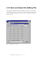
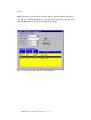
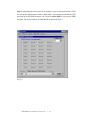
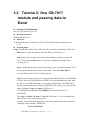
1
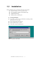
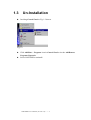
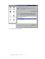
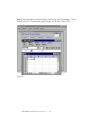
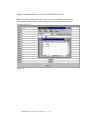
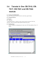
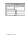
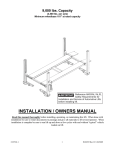
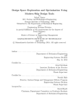
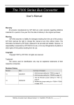
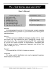
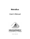
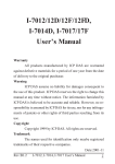
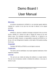
NAP7000D
User Manual
ComputerBoards, Inc.
Revision 1.0
July 1998
NAP7000D User Manual (Version 1.0) ---- 1
Table of Contents
1
2
3
NAP7000D INTRODUCTION..................................................................................................... 3
1.1
THE CONTENTS OF NAP7000D PACKAGE ................................................................................... 3
1.2
INSTALLATION ............................................................................................................................ 4
1.3
UN-INSTALLATION ...................................................................................................................... 5
1.4
SYSTEM DESCRIPTION................................................................................................................. 7
THE OPERATION OF NAP7000D ............................................................................................ 8
2.1
STARTING NAP7000D................................................................................................................ 8
2.2
THE MENU OF NAP7000D’S MAIN WINDOW............................................................................. 11
2.3
DETERMINE ALL CB-7000 MODULE CONFIGURATIONS ........................................................... 12
2.4
CHOOSE THE COM PORT AND BAUD RATE FOR SEARCH .......................................................... 14
2.5
CONTROL CB-7000 MODULE WITH NAP7000D........................................................................ 15
2.6
SETTING CB-7011/D, CB-7012/D,
2.7
SETTING THE CB-7017, CB-7018 ............................................................................................. 22
2.8
SETTING THE CB-7021.............................................................................................................. 25
2.9
SETTING CB-7041, CB-7052, CB-7053.................................................................................... 28
CB-7013/D, CB-7014/D ............................................. 16
2.10
SETTING CB-7042, CB-7043 AND CB-7067 ........................................................................ 31
2.11
SETTING CB-7044, CB-7050, CB-7060 ............................................................................... 33
2.12
DISPLAY THE SETTING RESULT ............................................................................................ 35
2.13
DISPLAY THE SEARCHING RESULT ....................................................................................... 36
2.14
SAVE AND OPEN THE SETTING FILE ..................................................................................... 37
2.15
TO EXIT THE NAP7000D ..................................................................................................... 38
NAP7000D TUTORIAL ............................................................................................................. 39
3.1
TUTORIAL 1: ONE CB-7017 MODULE ........................................................................................ 39
3.2
TUTORIAL 2: ONE CB-7017 MODULE AND PASSING DATA TO EXCEL ........................................ 43
3.3
TUTORIAL 3: ONE CB-7021 MODULE THE OUTPUT VALUE CONTROLLED BY EXCEL ............... 48
3.4
TUTORIAL 4: ONE CB-7012, CB-7017, CB-7021 AND CB-7044 MODULE ................................ 51
3.5
TUTORIAL 5: ONE CB-7012, CB-7017, CB-7021 AND CB-7044 MODULE WITH EXCEL ........... 53
NAP7000D User Manual (Version 1.0) ---- 2
1 NAP7000D Introduction
The NAP7000D is a hot-link DDE(Dynamic Data Exchange) server. The DDE is a
communication protocol that enables to exchange data between windows application.
The NAP7000 pass the data acquired from CB-7000 module to other application by
means of the hot-link. Or a user can control the CB-7000 module using the
NAP7000D after establishing these hot-link conversation. The NAP7000D is a mouse
driven system that provides the ability of developing CB-7000 application by just
clicking mouse.
1.1 The Contents of NAP7000D package
The NAP7000D package includes one disk and one manual:
NAP7000D User Manual (Version 1.0) ---- 3
1.2
Installation
Before Installing, please comfirm the following requirements:
z Microsoft Windows 95/NT operation system.
z A PC-compatible computer with Pentium chips.
z 16 MB RAM Memory.
z 2 MB hard disk available space.
z
z
z
z
z
Starting Installation
Insert disk 1 or disk 2 into your disk drive according to what
platform(95/NT) you using.
Then clicking Start in the task bar.
Enter A:Setup as Fig 1-1 shown
Click OK to start the install process.
Fig 1-1 install the NAP7000D.
NAP7000D User Manual (Version 1.0) ---- 4
1.3
z
Un-Installation
Invoking Control Panel as Fig 1-2 shown.
Fig 1-2
z
z
Click Add/Rem… Programs icon in Control Panel to invoke Add/Remove
Programs Properties.
Select NAP7000D to uninstall.
NAP7000D User Manual (Version 1.0) ---- 5
Fig 1-3 Uninstallation the NAP7000D.
NAP7000D User Manual (Version 1.0) ---- 6
1.4
z
System Description
NAP7000D
The NAP7000D is a software package that facility user to establish the DDE hotlink conversations between the NAP7000D and other Windows application. After
establishing these conversations, they can exchange information each other. For
example, a user can establish a conversation between NAP7000D to Excel. Then
he can pass the data from NAP7000D to a cell of a sheet in Excel. Further, the
user can analysis these data in this sheet by mean of Excel build in function. In
the following chapter, a tutorial with many examples are introduced that to guide
the user to familiar NAP7000D. With NAP7000D, a user take advantage of the
ability that to control the ICPCOM 7000 series module without having to code
the program.
z I7000.DLL and UART.DLL
The I7000.DLL and UART.DLL are the DLL(Dynamic Linking Library). These two
DLL consists of a set of functions for performing COM port operation. For more
detail information, please refer to NAP7000P User Manual.
z CB-7000 series module
The CB-7000 is a family of network data acquisition and control modules. They
provide A/D, D/A, DI/O, Timer/Counter and other function. For more detail
information, please refer various user manual for CB-7000 series.
NAP7000D User Manual (Version 1.0) ---- 7
2 The Operation of NAP7000D
2.1 Starting NAP7000D
To start the NAP7000D, click the Start in the task bar as Fig 2-1 shown.
Fig 2-1 Double the NAP7000D icon to start it.
NAP7000D User Manual (Version 1.0) ---- 8
When NAP7000D loading, a window pop up that show the startup information about
this software package. By default, the startup window will stay on about 3 second.
The user can disappear it by pressing the right button of the mouse. During the startup
time, the NAP7000D will detect automatically the COM port that the CB-7000
module attach to the computer. The startup information is shown as Fig 2-2.
Fig 2-2 The Startup information for NAP7000D.
NAP7000D User Manual (Version 1.0) ---- 9
After startup information window disappear, the NAP7000D’s main window will be
displayed as Fig 2-3. Also, the detected COM port that CB-7000 module attached to
the computer is displayed in the main window. The user may change the COM port
whenever he demand. For example, when pressing the right button of mouse during
startup time to quit the startup information. The displayed COM port may be wrong.
So the user must select the correct COM port that CB-7000 connected to the computer
before he going on.
Fig 2-3 The NAP7000D main window
NAP7000D User Manual (Version 1.0) ---- 10
2.2 The Menu of NAP7000D’s main
window
The NAP7000D’s main window contain 5 menus. Those are File, COM Port, Search,
Run DDE and Display.
Fig 2-4 The menu of NAP7000D’s main window.
And the File main menu contain three sub-menu. These sub-menu are Open, Save
and Exit.
Fig 2-5 The menu item in File menu.
The COM Port, Search and Run DDE do not contain any sub-menu.
The Display contains two sub-menu, those are Conv Setting Result and Search
Result.
Fig 2-6 The menu item in Display menu.
The detail information about these menu described in the following section.
NAP7000D User Manual (Version 1.0) ---- 11
2.3 Determine All CB-7000 Module
Configurations
In order to understand the configuration your remote control network comprised by
CB-7000 module. The user have to remember every module’s configuration
information. The configuration information for a CB-7000 module includes module
type(ie, 7520, 7014 etc), module’s baud rate, the module address in this network. To
record every module’s configuration information would be a annoyed burden when
constructing the network with large number CB-7000 modules. Or it is necessary to
understand every module’s configuration information when adding a module into the
original network in order to avoid conflict. The NAP7000D facilitate the booking by
performing the search process by clicking Search menu in the main window. After
performing Search, a window titled To Find Out CB-7000 Module… will display, as
fig 2-7 shown. It is strongly recommended to perform search process firstly to easy
the setting configuration for CB-7000 module.
NAP7000D User Manual (Version 1.0) ---- 12
Fig 2-7 The search window of NAP7000D.
Some information is shown to indicate that the searching status. Initially, the search
range for module address is from 0 to FF[hex]. The default COM port is the attached
COM port detected in startup time as fig 2-3 shown. And the baud rate may be choose
among 115200, 57600, 38400, 19200, 9600, 4800, 2400. Please refer to sec 2-4 to
choose the COM Port and baud rate for searching process. During the search
processing, user can quit in any time by click the Stop or Exit button. And the
searching result display in a window that represent the found module. All the
configuration information for every CB-7000 module will be displayed. It is useful to
debug the remote control network. And when establishing the hot-link conversation.
NAP7000D User Manual (Version 1.0) ---- 13
2.4 Choose the COM Port and
Baud Rate for Search
Please following these steps to choose the COM port and baud rate that determine the
searching range.
Fig 2-8 Setting the COM Port and Baud Rates.
NAP7000D User Manual (Version 1.0) ---- 14
2.5 Control CB-7000 module with
NAP7000D
Basically, the NAP7000D divided the CB-7000 series module into six catalogues
according to its function. These six catalogues are listed as follows:
z Analog Input with one channel
These are CB-7011/D, CB-7012/D, CB-7013/D and CB-7014/D.
z Analog Input with eight channels
These are CB-7017 and CB-7018.
z Analog Output with one channel
These is CB-7021.
z Digital Input Only
These are CB-7041, CB-7052 and CB-7053.
z Digital Output Only
These are CB-7042, CB-7043 and CB-7067.
z Digital Input and Digital Output Both
These are CB-7044, CB-7050 and CB-7060.
The setting configuration step is different for setting CB-7000 in these six catalogues.
The setting configuration step will be introduced in following content.
NAP7000D User Manual (Version 1.0) ---- 15
2.6 Setting CB-7011/D, CB-7012/D,
CB-7013/D, CB-7014/D
Step1: Check a ConvN(here N means 0 to 31) to start the setting CB-7000 module
configuration. In this example, we check Conv0 for demos purpose as shown in fig 29. A user can check any ConvN to start its module configuration setting. After
checked, a window titled setting CB-7000 Module Configuration will pop up. We
have to set the module type, baud rate, module address and checksum in this window
for this DDE conversation working properly.
Fig 2-9 Check a ConvN to start module configuration setting.
NAP7000D User Manual (Version 1.0) ---- 16
Fig 2-9 shown the state that hasn’t performed searching process.
Fig 2-9
NAP7000D User Manual (Version 1.0) ---- 17
Step 2: Select the desired module type as method 1 or method 2. In this case, please
select 7012 as fig 2-10 shown.
Fig 2-10 select the desired module.
If selecting 7012/D by method 1 then the following step3, step4 and step 5 is
necessary. If using method 2 then skip step3, step4 and step5.
Step 3:
1.
Entry the module address for the selected module. In this case, please enter
Step 4: Select the exact baud rate in the Baud Rate Combo for the selected module.
In this case, please select 9600.
Step 5:
Select the status of checksum(Disable or Enable) for your CB-7012D.
Notice, the status of checksum must be exact to your physical CB-7012D module
device. If you select Enable, you must to enable checksum status for CB-7012D. The
NAP7000D User Manual (Version 1.0) ---- 18
default setting for CB-7000 series module is disable.
After about five steps, the setting window shown as Fig 2-11.
Fig 2-11 After setting the module configuration.
Step 6: when Fig 2-11 display, click OK button to accept the setting or click Cancel
button to cancel the setting. After OK button is clicked, the main window of
NAP7000D display as Fig 2-12 to tell the user these setting step is completed..
NAP7000D User Manual (Version 1.0) ---- 19
Fig 2-12 The main window for NAP7000D when completing a setting.
The user can move the mouse point to the checked Conv0. Then press the right button
of mouse to retrieve the setting information. And a information window would be
toggled on as Fig 2-13 shown. Again pressing the right button may toggle off the
information window.
NAP7000D User Manual (Version 1.0) ---- 20
Fig 2-13 Toggle on the information window.
NAP7000D User Manual (Version 1.0) ---- 21
2.7 Setting the CB-7017, CB-7018
Step1: Check a ConvN(here N means 0 to 31) to start the setting CB-7000 module
configuration. In this example, the Conv8 is checked.
Step 2: Select the desired module type as Fig 2-10 shown(method 1 or method 2).
In this case, please select 7017 or 7018. In this examples, the 7017 is selected.
Step 3: After selecting 7017, a window titled 7017/7018 Channel selection will
pop up as Fig 2-14 shown. The user can check the desired input channel to received
analog input data. Or just push Select All button to select all eight channels. After
check the desire channels then push OK button to complete the channel selection. Or
pushing Cancel button to cancel the channel selection.
Fig 2-14 The 7017/7018 Channel Selection window.
NAP7000D User Manual (Version 1.0) ---- 22
Step 4:
Entry the module address for the selected module.
Step 5:
Select the exact baud rate in the Baud Rate Combo for the selected module.
Step 6: Select the status of checksum(Disable or Enable). Notice, the status of
checksum must be exact to your physical CB-7000 series module device. If you
select Enable, you must to enable checksum status for CB-7000 module. The default
setting for CB-7000 series module is disable.
After above six steps, the setting window shown as Fig 2-15.
Fig 2-15 After setting the module configuration.
Step 7: when Fig 2-15 display, click OK button to accept the setting.
NAP7000D User Manual (Version 1.0) ---- 23
The user can move the mouse point to the checked Conv8. Then press the right button
of mouse to retrieve the setting information. And a information window would be
toggled on as fig 2-16 shown. Again pressing the right button may toggle off the
information window.
Fig 2-16 Toggle on the information window for Conv8.
NAP7000D User Manual (Version 1.0) ---- 24
2.8
Setting the CB-7021
Step1: Check a ConvN(here N means 0 to 31) to start the setting CB-7000 module
configuration. In this examples, the Conv16 is checked.
Step 2: Select the module type as Fig 2-10 shown. In this case, please select 7021.
After selecting 7021, then a window titled setting 7021 will pop up as fig 2-17 shown.
Fig 2-17 The setting 7021 window.
NAP7000D User Manual (Version 1.0) ---- 25
There are three command buttons in Fig 2-17, those are Output Assigned Value,
Output ReadBack Value and Output via DDE link. It is means that the desired output
value(voltage) for CB-7021 can be given with 3 ways as following:
z Output Assigned Value: to assign the output value directly.
z Output ReadBack Value: the read back value of CB-7021 as the desired
output value:
z Output via DDE link: to output value of CB-7021 is controlled by DDE
hot-link as Fig 2-18 shown.
Fig 2-18 Control the CB-7021 output voltage by means of DDE link.
With the DDE hot-link, a user can control the CB-7021 without any programming.
When establishing the DDE hot-link conversation, the user must fill out “Service”,
“Topic” and “Item” fields in the 7021 setting window. Usually, the content in
“Service” field is just the application’s name such as “Excel”, “Genie”. The content in
“Topic” field is the working sheet or document in the application such as “sheet1” for
Excel, “STRTGY1” for Genie. The content in “Item” field is the item’s name that
contain the value to be passed. For examples, “DDES1” for Genie. A cell in Excel
will be referred to by the representation as row number and column number. For
example, when using A1 cell, then the content in “Item” field would be “R1C1”. And
the C2 cell would be “R2C3”.
Fig 2-19 show setting the DDE link to the Excel application. The value in the A1 cell
of sheet1 would be passed to the NAP7000D. The NAP7000D controls the CB-7021
to output the desired voltage.
NAP7000D User Manual (Version 1.0) ---- 26
Fig 2-19 Control the desired output value of CB-7021 by Excel.
Step 3:
Pressing one of these 3 command buttons to decide the output value. .
Step 4:
3.
Entry the module address for the selected module. In this case, please enter
Step 5:
Select the exact baud rate in the Baud Rate Combo for the selected module.
Step 6: Select the status of checksum(Disable or Enable). Notice, the status of
checksum must be exact to your physical CB-7000 series module device. If you
select Enable, you must to enable checksum status for CB-7000 module. The default
setting for CB-7000 series module is disable.
After above six steps, the setting window shown as Fig 2-21.
NAP7000D User Manual (Version 1.0) ---- 27
Fig 2-21.
Step 7: when Fig 2-21 display, click OK button to accept the setting.
2.9 Setting CB-7041, CB-7052, CB7053
Step1:
Check a ConvN(here N means 0 to 31) to start the setting CB-7000 module
configuration. In this example, the Conv1 is checked.
Step 2:
Select the desired module type as Fig 2-10 shown(method 1 or method 2).
In this case, please select 7041, 7052 or 7053. In this examples, the 7041 is
selected.
NAP7000D User Manual (Version 1.0) ---- 28
Step 3:
After selecting 7041, a window titled setting Configuration for 7041 will
pop up as Fig 2-22 shown.
Fig 2-22 The setting Configuration for 7041 window.
This window given some information about the CB-7041 module. Because CB-7041
is just a digital input module. The portion of Digital Output is gray that means the
user can not set in this portion. And the portion of Digital Input show that there are 14
digital input channel. Pressing the Digital Input button means this CB-7041 module
perform the digital input function.
Step 4:
Entry the module address for the selected module.
Step 5:
Select the exact baud rate in the Baud Rate Combo for the selected module.
Step 6: Select the status of checksum(Disable or Enable). Notice, the status of
checksum must be exact to your physical CB-7000 series module device. If you
select Enable, you must to enable checksum status for CB-7000 module. The default
setting for CB-7000 series module is disable.
The Step 4, Step 5 and Step 6 can be skipped if invoking setting Configuration for
NAP7000D User Manual (Version 1.0) ---- 29
7041 window with method 2.(please referring Fig 2-10)
After above six steps, the setting window shown as Fig 2-23.
Fig 2-23
Step 7: Clicking OK button to accept the setting.
NAP7000D User Manual (Version 1.0) ---- 30
2.10 Setting CB-7042, CB-7043 and
CB-7067
Step1: Check a ConvN(here N means 0 to 31) to start the setting CB-7000 module
configuration. In this example, the Conv9 is checked.
Step 2: Select the desired module type as Fig 2-10 shown(method 1 or method 2).
In this case, please select 7042, 7043 or 7067. In this examples, the 7042 is selected.
Step 3: After selecting 7042, a window titled setting Configuration for 7042 will
pop up as Fig 2-24 shown.
Fig 2-24 The setting Configuration for 7042 window.
This window given some information about the CB-7042 module. Because CB-7042
is just a digital output module. The portion of Digital input is gray that means the user
can not set in this portion. And the portion of Digital Output show that there are 13
digital output channel. As the CB-7021, the user can decide the output value with 3
ways. Those are Output Assigned Value, Output ReadBack Value and Output via
NAP7000D User Manual (Version 1.0) ---- 31
DDE Link.
Step 4: Entry the module address for the selected module.
Step 5:
Select the exact baud rate in the Baud Rate Combo for the selected module.
Step 6: Select the status of checksum(Disable or Enable). Notice, the status of
checksum must be exact to your physical CB-7000 series module device. If you
select Enable, you must to enable checksum status for CB-7000 module. The default
setting for CB-7000 series module is disable.
The Step 4, Step 5 and Step 6 can be skipped if invoking setting Configuration for
7042 window with method 2.(please referring Fig 2-10)
Step 7: Clicking OK button to accept the setting.
NAP7000D User Manual (Version 1.0) ---- 32
2.11 Setting CB-7044, CB-7050, CB7060
Step1: Check a ConvN(here N means 0 to 31) to start the setting CB-7000 module
configuration. In this example, the Conv17 is checked.
Step 2: Select the desired module type as Fig 2-10 shown(method 1 or method 2).
In this case, please select 7044, 7050 or 7060. In this examples, the 7044 is selected.
Step 3: After selecting 7044, a window titled setting Configuration for 7044 will
pop up as Fig 2-25 shown.
Fig 2-25 The setting Configuration for 7044 window.
This window given some information about the CB-7044 module. Because CB-7044
is digital input/output module. All the portion of Digital Input and Digital Output is
active. The user can set in all portion. And the portion of Digital Input show that there
are 4 digital input channels. Digital Output show that there are 8 digital output
channels. When push Digital Input button in the Digital Input portion. When push
one command button among Output Assigned Value, Output Read Back Value and
NAP7000D User Manual (Version 1.0) ---- 33
Output via DDE Link button in the Digital output portion. This CB-7044 would
perform the digital output function.
Step 4: Entry the module address for the selected module.
Step 5:
Select the exact baud rate in the Baud Rate Combo for the selected module.
Step 6: Select the status of checksum(Disable or Enable). Notice, the status of
checksum must be exact to your physical CB-7000 series module device. If you
select Enable, you must to enable checksum status for CB-7000 module. The default
setting for CB-7000 series module is disable.
The Step 4, Step 5 and Step 6 can be skipped if invoking setting Configuration for
7044 window with method 2.(please referring Fig 2-10)
Step 7: Clicking OK button to accept the setting.
NAP7000D User Manual (Version 1.0) ---- 34
2.12 Display the Setting Result
After setting the configuration for CB-7000 modules. The user can get the setting
information by click Display / Conv Setting Result menu as Fig 2-26 shown.
Fig 2-26.
After click Conv Setting Result menu, a window titled Display DDE Conversation
Setting Information will pop up as Fig 2-27 shown. The user can get whole
information of all module setting. It is facility utility that understanding the
configuration of your remote control system.
Fig 2-27. Display DDE Conversation Setting Information window.
NAP7000D User Manual (Version 1.0) ---- 35
2.13 Display the Searching Result
After searching the CB-7000 modules. The user can get the searching result by click
Display / Search Result menu as fig 2-28 shown.
Fig 2-28
After click Search Result menu, a window titled The searching Result will pop up as
fig 2-29 shown.
Fig 2-29.
NAP7000D User Manual (Version 1.0) ---- 36
2.14 Save and Open the Setting File
After setting the configuration for CB-7000 modules. The user can save the setting
configuration information in a file with .CON extension file name. And retrieved the
setting configuration information by open the saved file. The Open and Save menu
shown as fig 2-30.
Fig 2-30 Open/Save the .con file.
NAP7000D User Manual (Version 1.0) ---- 37
2.15 To Exit the NAP7000D
When want to exit NAP7000D, the user can click Exit menu to exit the NAP7000D as
shown in Fig 2-31.
Fig 2-31.
NAP7000D User Manual (Version 1.0) ---- 38
3
NAP7000D Tutorial
3.1 Tutorial 1: One CB-7017
module
z Working CB-7000 Module:
one CB-7520 and One CB-7017
z Working Software:
NAP7000D.
z Function:
To demonstrate how to control the CB-7017 by NAP7000D
z Working Steps:
Step 1: Setting the configuration of the CB-7017, and select all channels as Fig 3-1
shown. Then click OK button to accept the channel selection.
NAP7000D User Manual (Version 1.0) ---- 39
Fig 3-1.
step 2: Enter the exact baud rate, module address and checksum according to
your CB-7017 configuration(please referring Fig 2-10) as Fig 3-2 shown. Then
click the OK button to accept the configuration setting
Fig 3-2. Accept the setting CB-7017 configuration.
NAP7000D User Manual (Version 1.0) ---- 40
Step 3: Adjusting the timer interval according to your system performance. Here
we accept the default interval that is 1000 mSec. It mean the period that the CPU
perform the NAP7000D function call. Then click Run DDE to activate the DDE
hot-link. The main window of NAP7000D as shown in Fig 4-3.
Fig 3-3.
NAP7000D User Manual (Version 1.0) ---- 41
After Run DDE is clicked, a window title DDE Conversation Channel will pop up.
The input value for every channel is displayed in first conversation channel as Fig 34. These values may change every one second because the timer interval is set to 1000
mSec.
In this examples, the input value of channel 0 of CB-7017 is 3.674V, and the input
value of channel 4 is 1.518V.
Fig 3-4.
Step 4: Click Quit command button to quit the DDE running.
NAP7000D User Manual (Version 1.0) ---- 42
3.2 Tutorial 2: One CB-7017
module and passing data to
Excel
z Working CB-7000 Module:
one CB-7520 and One CB-7017
z Working Software:
NAP7000D and Excel.
z Function:
To demonstrate how to control the CB-7017 by NAP7000D then passing data to
excel.
z Working Steps:
Step 1: Setting the configuration of the CB-7017, and select all channels. Then click
OK button to accept the channel selection. Please referring Fig 3-1.
Step 2: Enter the exact baud rate and module address according to your CB7017. Then click the OK button to accept the configuration setting. Please
referring Fig 3-2.
Step 3: Adjusting the timer interval according to your system performance. Here
we accept the default interval that is 1000 mSec. Then click Run DDE to
activate DDE hot-link. Please referring Fig 4-3.
Step 4: Activating Excel. Now we need establish DDE link between NAP7000D
to Excel. Here, the NAP7000D act as DDE server that publishing the data. And
the Excel act as DDE client that receiving the published data. The DDE client
has the responsibility that creating the DDE link. This require you to provide the
name of Service, Topic and Item of DDE server.
In NAP7000D, the Service is NAP7000D, the executed file name of
NAP7000D.
The Topic is Form5 and Item is TextN(here N means 1 to 32 according to the
data in what conversation to be passed).
Usually, in most Windows application, the client combine these three names in
following form to identify a DDE link.
Service|Topic!Item
NAP7000D User Manual (Version 1.0) ---- 43
Therefore, specifying the DDE link with
NAP7000D|Form5!TextN (where N is 1 to 32)
when working with NAP7000D.
Now selecting a cell of Excel, for example, A1 cell. Then typing
=NAP7000D|FORM5!TEXT1 into the cell as Fig 3-5 shown. Then pressing
Enter to accept the typing, and the A1 will receive the data coming from
NAP7000D as shown in Fig 3-6..
Fig 3-5.
NAP7000D User Manual (Version 1.0) ---- 44
Fig 3-6. Passing data from NAP7000D to Excel.
NAP7000D User Manual (Version 1.0) ---- 45
Further, when needing analysis the data of each channel of CB-7017. Typing MID()
function in a cell of Excel. For example, the channel 0’s value is retrieved in A2 by
keying =MID(A1,1,7) as Fig 3-7 shown.
Fig 3-7 To retrieve channel 0’s value into a cell by mean of MID() function.
The retrieved value shown as Fig 3-8
Fig 3-8 The retrieved value displayed in the cell.
NAP7000D User Manual (Version 1.0) ---- 46
Fig 3-9 and Fig 3-10 show how to retrieve channel 1’s value and display its value in
Excel.
Fig 3-9 To retrieve channel 1’s value into a cell by mean of MID() function.
Fig 3-10 The retrieved value displayed in the cell.
NAP7000D User Manual (Version 1.0) ---- 47
3.3 Tutorial 3: One CB-7021
module the Output Value
Controlled By Excel
z Working CB-7000 Module:
one CB-7520 and One CB-7021
z Working Software:
NAP7000D and Excel.
z Function:
To demonstrate how to passing the value from Excel to CB-7021.
z
Working Steps:
Step 1: Setting the configuration of the CB-7021 as Fig 3-11 shown. Please
adjusting the baud rate and module address according to your CB-7021 module
configuration. In this case, the A1 cell of Excel which contain the value passing
to NAP7000D.
Fig 3-11.
NAP7000D User Manual (Version 1.0) ---- 48
Step 2: Activating Excel. Then entering a value in A1 cell, for examples, 1.23 as
shown in Fig 3-12. It means the output voltage of CB-7021 will be 1.23V.
Fig 3.12.
NAP7000D User Manual (Version 1.0) ---- 49
Step 3: Click Run DDE menu to start NAP7000D function call.
Step 4: Trying to change the value of A1 cell of Excel, then the value in first
conversation channel may vary according to the value in A1 cell of Excel as
shown in Fig 3-14.
Fig 3-14.
NAP7000D User Manual (Version 1.0) ---- 50
3.4 Tutorial 4: One CB-7012, CB7017, CB-7021 and CB-7044
module
z Working CB-7000 Module:
one CB-7520 and One CB-7012, CB-7017, CB-7021 and CB-7044.
z Working Software:
NAP7000D
z Function:
To demonstrate how to control a remote control network consist of CB-7012,
CB-7017, CB-7021 and CB-7044 in different baud rate speed.
z
Working Steps:
Step 1: Setting the configurations for these four CB-7000 modules as Fig 3-15
shown.
NAP7000D User Manual (Version 1.0) ---- 51
Fig 3-15 The various information for DDE conversation setting.
Step 2: Adjusting the timer interval according to your system performance. Here
we accept the default interval that is 1000 mSec. It mean the period that the CPU
perform the NAP7000D function call.
Step 3: Click Run DDE menu to start DDE hot-link. After Run DDE is clicked,
a window title DDE Conversation Channel will pop up. The input/output value
for every CB-7000 module is displayed in first 4 conversation channels as Fig 316. There are:
z 1st Conv: the analog input value of CB-7012D.
z 2nd Conv: The assigned analog output value of CB-7021.
z 3rd Conv: The analog input value for each input channel of CB-7017.
z 4th Conv: The assigned output value of CB-7044.
Fig 3-16
NAP7000D User Manual (Version 1.0) ---- 52
3.5 Tutorial 5: One CB-7012, CB7017, CB-7021 and CB-7044
module with Excel
z Working CB-7000 Module:
one CB-7520 and One CB-7012, CB-7017, CB-7021 and CB-7044.
z Wording Software:
NAP7000D and Excel.
z Function:
To demonstrate how to control a remote control network consist of CB-7012,
CB-7017, CB-7021 and CB-7044. Here the CB-7021 and CB-7044 control by Excel.
z
Working Steps:
Step 1: Setting the configurations for these four CB-7000 modules as Fig 3-17
shown. Please adjusting the baud rate and module address according to your CB7000 module configuration.
NAP7000D User Manual (Version 1.0) ---- 53
Fig 3-17.
Step 2: Activating Excel. Then entering a value in A1 and A2 cell. For
examples, 2.34 in A1. It means the analog output voltage of CB-7021 will be
2.34V. Then typing 15 in A2. It means the digital output value of CB-7044 is
F[hex]. Please referring Fig 3-18.
NAP7000D User Manual (Version 1.0) ---- 54
Fig 3-18.
Step 3: Click Run DDE button to start DDE hot-link. After that, the DDE
Conversation Channel window will pop up as Fig 3-19 shown.
Fig 3-19.
Step 4: Trying to change the value of A1 and A2 cell of Excel, then the value in
second and fourth conversation channel vary according to the value in A1 and
A2 cell of Excel as shown in Fig 3-20.
NAP7000D User Manual (Version 1.0) ---- 55
Fig 3-20.
NAP7000D User Manual (Version 1.0) ---- 56