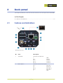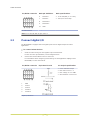
1
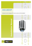
BC620WDR Series
Installation Manual
IP box camera with dual H.264 and WDR
Note: To ensure proper operation, please read this manual thoroughly before using the
product and retain the information for future reference.
Copyright © 2015 Siqura B.V.
All rights reserved.
BC620WDR v4.17
Installation Manual v2 (140705-2)
AIT55
Nothing from this publication may be copied, translated, reproduced, and/or published by
means of printing, photocopying, or by any other means without the prior written permission
of Siqura.
Siqura reserves the right to modify specifications stated in this manual.
Brand names
Any brand names mentioned in this manual are registered trademarks of their respective
owners.
Liability
Siqura accepts no liability for claims from third parties arising from improper use other than
that stated in this manual.
Although considerable care has been taken to ensure a correct and suitably comprehensive
description of all relevant product components, this manual may nonetheless contain errors
and inaccuracies. We invite you to offer your suggestions and comments by email via
[email protected]. Your feedback will help us to further improve our documentation.
How to contact us
If you have any comments or queries concerning any aspect related to the product, do not
hesitate to contact:
Siqura B.V.
Zuidelijk Halfrond 4
2801 DD Gouda
The Netherlands
General : +31 182 592 333
Fax : +31 182 592 123
E-mail : [email protected]
WWW : www.siqura.com
2
Contents
1
2
About this manual .....................................................................................
4
Safety and compliance ..............................................................................
5
2.1
2.2
2.3
3
4
Safety ................................................................................................
Cautions .............................................................................................
Compliance .........................................................................................
5
7
8
Product overview ......................................................................................
9
3.1
3.2
Models ...............................................................................................
Features .............................................................................................
9
10
3.3
3.4
Package contents .................................................................................
Dimensions .........................................................................................
11
11
Back panel ................................................................................................
4.1
5
12
Cable connection .......................................................................................
14
5.1
5.2
5.3
5.4
5.5
5.6
6
Connect audio .....................................................................................
Connect data RS-485 ...........................................................................
Connect digital I/O ...............................................................................
Power the camera ................................................................................
Connect to network ..............................................................................
Use the analogue video output ..............................................................
14
14
15
16
16
17
Mount the lens and the camera .................................................................
18
6.1
6.2
6.3
7
12
Features and indications .......................................................................
Mount the lens ....................................................................................
Mount the camera ................................................................................
PID Camera installation ........................................................................
18
19
19
System ......................................................................................................
20
7.1
7.2
System requirements ...........................................................................
System compatibility ............................................................................
20
20
Appendix: Use focus assist ........................................................................
21
Appendix: Adjust back focus .....................................................................
22
Index ......................................................................................................
23
3
1
About this manual
What this manual covers
This manual describes how to install and connect the BC620WDR, Siqura's IP box camera with
dual H.264 and WDR. Instructions for configuration and operation of the BC620WDR can be
found in the User Manual.
Who should read this manual
This manual is intended for technicians involved in the installation of BC620WDR cameras.
What you should already know
To be able to install and connect the BC620WDR properly, you should have adequate
knowledge and skills in the following fields.
●
CCTV systems and components
●
Electrical wiring and low-voltage electrical connections
●
Connections between fiber optical equipment (SFP models)
●
Ethernet network technologies and Internet Protocol (IP)
●
Windows environments
●
Web browsers
●
Video, audio, data, and contact closure transmissions
Before you start the installation
We advise you to read and observe all instructions and warnings in this manual before you
proceed. Retain this manual with the original bill of sale for future reference and warranty
service. When you unpack your product, check for missing or damaged items. If any item is
missing, or if damage is evident, do not install or operate this product. Contact your supplier
for assistance.
Why specifications may change
At Siqura, we are committed to delivering high-quality products and services. The information
given in this manual was current when published. As we continuously seek to improve our
products and user experience, all features and specifications are subject to change without
notice.
We like to hear from you!
Customer satisfaction is our first priority. We welcome and value your opinion about our
products and services. Should you detect errors or inaccuracies in this manual, we would be
grateful if you would inform us. We invite you to offer your suggestions and comments via
[email protected]. Your feedback helps us to further improve our documentation.
4
2
Safety and compliance
This chapter presents the BC620WDR safety instructions and compliance information.
In This Chapter
2.1 Safety................................................................................................................... 5
2.2 Cautions................................................................................................................7
2.3 Compliance............................................................................................................8
2.1
Safety
The safety information contained in this section, and on other pages of this manual, must be
observed whenever this unit is operated, serviced, or repaired. Failure to comply with any
precaution, warning, or instruction noted in the manual is in violation of the standards of
design, manufacture, and intended use of the module. Siqura assumes no liability for the
customer's failure to comply with any of these safety requirements.
Trained personnel
Installation, adjustment, maintenance, and repair of this equipment are to be performed by
trained personnel aware of the hazards involved. For correct and safe use of the equipment
and in order to keep the equipment in a safe condition, it is essential that both operating and
servicing personnel follow standard safety procedures in addition to the safety precautions
and warnings specified in this manual, and that this unit be installed in locations accessible to
trained service personnel only.
Safety requirements
The equipment described in this manual has been designed and tested according to the
UL/IEC/EN 60950-1 safety requirements. See the CE Declaration of Conformity for
compliance information.
Warning: If there is any doubt regarding the safety of the equipment, do not put it into
operation.
This might be the case when the equipment shows physical damage or is stressed beyond
tolerable limits (for example, during storage and transportation).
Important: Before opening the equipment, disconnect it from all power sources.
The equipment must be powered by a SELV1 power supply. This is equivalent to a Limited
Power source (LPS, see UL/IEC/EN 60950-1 clause 2.5) or a "NEC Class 2" power supply.
When this module is operated in extremely elevated temperature conditions, it is possible for
internal and external metal surfaces to become extremely hot.
1. SELV: conforming to IEC 60950-1, <60 Vdc output, output voltage galvanically isolated
from mains. All power supplies or power supply cabinets available from Siqura comply with
these SELV requirements.
5
Safety and compliance
Power source and temperature ratings
Verify that the power source is appropriate before you plug in and operate the unit. Use the
unit under conditions where the temperature remains within the range given in the Technical
Specifications of this product.
Optical safety
The following optical safety information applies to BC620WDR models with SFP interface.
This product complies with 21 CFR 1040.10 and 1040.11 except for deviations pursuant to
Laser Notice No. 50, dated June 24, 2007. This optical equipment contains Class 1M lasers or
LEDs and has been designed and tested to meet IEC 60825-1:1993+A1+A2 and IEC
60825-2:2004 safety class 1M requirements.
Warning: Optical equipment presents potential hazards to testing and servicing personnel,
owing to high levels of optical radiation.
When using magnifying optical instruments, avoid looking directly into the output of an
operating transmitter or into the end of a fiber connected to an operating transmitter, or there
will be a risk of permanent eye damage. Precautions should be taken to prevent exposure to
optical radiation when the unit is removed from its enclosure or when the fiber is disconnected
from the unit. The optical radiation is invisible to the eye.
Use of controls or adjustments or procedures other than those specified herein may result in
hazardous radiation exposure.
The installer is responsible for ensuring that the label depicted below (background: yellow;
border and text: black) is present in the restricted locations where this equipment is installed.
EMC
This device has been tested and found to meet the CE regulations relating to EMC and
complies with Part 15 of the FCC rules. Operation is subject to the following two conditions:
(1) This device may not cause harmful interference, and (2) This device must accept any
interference received, including interference that may cause undesired operation. These limits
are designed to provide reasonable protection against interference to radio communications in
any installation. The equipment generates, uses, and can radiate radio frequency energy;
improper use or special circumstances may cause interference to other equipment or a
performance decrease due to interference radiated by other equipment. In such cases, the
user will have to take appropriate measures to reduce such interactions between this and
other equipment.
Any interruption of the shielding inside or outside the equipment could make the equipment
more prone to fail EMC requirements.
Non-video signal lines must use appropriate shielded Cat 5 cabling (S-FTP), or at least an
equivalent. Ensure that all electrically connected components are carefully earthed and
protected against surges (high voltage transients caused by switching or lightning).
ESD
Electrostatic discharge (ESD) can damage or destroy electronic components. Proper
precautions should be taken against ESD when opening the equipment.
6
Safety and compliance
RoHS statement
Global concerns over the health and environmental risks associated with the
use of certain environmentally-sensitive materials in electronic products have
led the European Union (EU) to enact the Directive on the Restriction of the
use of certain Hazardous Substances (RoHS) (2002/95/EC). Siqura offers
products that comply with the EU’s RoHS Directive. The full version of the
Siqura RoHS statement can be viewed at www.siqura.com.
Product disposal
The unit contains valuable materials which qualify for recycling. In the
interest of protecting the natural environment, properly recycling the unit at
the end of its service life is imperative.
When processing the printed circuit board, dismantling the lithium battery
calls for special attention. This kind of battery, a button cell type, contains so
little lithium, that it will never be classified as reactive hazardous waste. It is
safe for normal disposal, as required for batteries by your local authority.
2.2
Cautions
Handle the camera carefully
Do not abuse the camera. Avoid bumping and shaking. The camera can be damaged by
improper handling or storage.
Do not disassemble the camera
To prevent electric shock, do not remove screws or covers. There are no user serviceable
parts inside. Consult technical support if a camera is suspected of malfunctioning.
Never face the camera towards the sun
Do not aim the camera at bright objects. Whether the camera is in use or not, never aim it at
the sun or other extremely bright objects, as this can damage the camera.
Do not expose indoor models to moisture
The indoor camera model is designed for indoor use or use in locations where it is protected
from rain and moisture. Turn the power off immediately if the camera is wet and ask a
qualified technician for servicing. Moisture can damage the camera and also create the danger
of electric shock.
Do not use strong or abrasive detergents to clean the camera
Use a dry cloth to clean the camera when it is dirty. If the dirt is hard to remove, use a mild
detergent and wipe gently. To clean the lens, use lens tissue or a cotton tipped applicator and
ethanol. Do not clean the lens with strong detergents.
7
Safety and compliance
2.3
Compliance
8
3
Product overview
This chapter introduces the BC620WDR and its features.
In This Chapter
3.1 Models.................................................................................................................. 9
3.2 Features.............................................................................................................. 10
3.3 Package contents.................................................................................................. 11
3.4 Dimensions.......................................................................................................... 11
3.1
Models
The BC620WDR series includes the following models.
Model
Description
BC620WDR
Network box camera, super WDR, D1 resolution, dual H.264
BC620WDR/SFP
Network box camera, super WDR, D1 resolution, dual H.264, SFP
interface
BC620WDR-AID
Network box camera, super WDR, AID, D1 resolution, dual H.264
BC620WDR-AID/SFP
Network box camera, super WDR, AID, D1 resolution, dual H.264,
SFP interface
BC620WDR-TDC
Network box camera, super WDR, TDC, D1 resolution, dual H.264
BC620WDR-TDC/SFP
Network box camera, super WDR, TDC, D1 resolution, dual H.264,
SFP interface
BC620WDR-PID
Network box camera, super WDR, PID, D1 resolution, dual H.264
BC620WDR-PID/SFP
Network box camera, super WDR, PID, D1 resolution, dual H.264,
SFP interface
Note: The BC620WDR can be configured to either NTSC or PAL, with the default set to PAL
for EMEA and APAC, and to NTSC for the US.
9
Product overview
3.2
Features
BC620WDR Series
Common features
●
1/3” Pixim DPS Seawolf Imager
●
D1 resolution
●
ONVIF Profile S
●
Day/Night with IR-cut filter
●
Wide dynamic range
●
Backlight compensation
●
Alarm: two inputs / two outputs
●
Analogue video output
●
Two-way audio
●
Up to 10 privacy masks
●
24 Vac; 12 Vdc / 24 Vdc; 802.3af PoE
●
SFP Interface (optional)
●
SD card slot for edge recording
BC620WDR-AID &
BC620WDR-TDC
Features
●
Common features (see above)
●
Traficon-powered incident detection
BC620WDR-PID
Features
●
Common features (see above)
●
Built-in analytics for perimeter intrusion
detection (PID)
10
Product overview
3.3
3.4
Package contents
BC620WDR
(lens not included)
C mount lens adapter
Back focus adjuster
5-Pin terminal block (2x)
2-Pin terminal block
Power adapter
CD (Manuals and software)
Quick Start Guide
Dimensions
11
4
Back panel
This chapter describes the connectors and other features on the back panel of the BC620WDR.
In This Chapter
4.1 Features and indications........................................................................................ 12
4.1
Features and indications
BC620WDR back panel
No.
Item
Description
1
CC IN/OUT
Connector for digital I/O
┴
IN 1
IN 2
OUT 1
OUT 2
2
DATA IN/OUT
:
:
:
:
:
GND
CC IN 1
CC IN 2
CC OUT 1
CC OUT 2
Connector for Data RS-422/485
IN +
IN OUT +
OUT ┴
12
:
:
:
:
:
DATA IN +
IDATA IN DATA OUT +
DATA OUT GND
Back panel
No.
Item
Description
3
Video (BNC)
Connector for analogue video output
4
FOCUS ASSIST
Activates Focus Assist function. Helps to
achieve optimal image quality (see Appendix:
Use focus assist).
5
Micro SD card slot
Cards up to 32 GB supported.
6
SYNC
Sync LED
7
AUDIO IN / AUDIO OUT
Connectors for two-way audio transmission
8
PWR
Power connection indicator (also used for Focus
Assist)
9
Network LEDs
Network connection and activity indicators
10
Power connector
11-30 Vdc / 20-30 Vac
11
Network connector
RJ-45 with 802.3af PoE
12
SFP connector (on SFP model)
Used for direct connection to fiber optic cabling
or coax (via Siqura ECO-plug)
13
Reset button
Press and hold for 10 sec. to reset to factory
defaults (incl. network settings).
13
5
Cable connection
This chapter explains how to connect power and signal cables.
In This Chapter
5.1 Connect audio...................................................................................................... 14
5.2 Connect data RS-485.............................................................................................14
5.3 Connect digital I/O................................................................................................ 15
5.4 Power the camera................................................................................................. 16
5.5 Connect to network............................................................................................... 16
5.6 Use the analogue video output................................................................................17
5.1
Connect audio
The BC620WDR camera supports two-way audio.
To connect audio
●
Connect the audio input and output cables (jack Ø3.5 mm) to the AUDIO IN and AUDIO
OUT connectors on the back panel of the camera.
For information about configuring audio settings via the Audio webpage of the BC620WDR,
see the User Manual.
5.2
Connect data RS-485
The BC620WDR itself does not have PTZ functionality, but it can be mounted on a PTZ
mounting bracket which can then be controlled from the data port (RS-422/485) on the back
panel of the BC620WDR.
To connect data RS-485
1
Insert the data wiring into the supplied 5-pin terminal block.
For the connector pin definitions, see the diagram below.
2
Connect the terminal block to the DATA connector.
For information about configuring data settings via the Data RS-485 webpage of the
BC620WDR, see the User Manual.
14
Cable connection
CC/DATA connector
Data pin definitions
6.
Data specifications
DATA IN +
●
1x RS-422/485 (2- or 4-wire)
7.
DATA IN –
●
300 b/s to 230.4 kbps
8.
DATA OUT +
9.
DATA OUT –
10.
GND
RS-485 definitions
Note: For 2-wire RS-485 use pins 6 and 7.
5.3
Connect digital I/O
The BC620WDR is equipped with two digital inputs and two digital outputs for alarm
applications.
To connect alarm devices
1
Insert the alarm wiring into the supplied 5-pin terminal block.
For the connector pin definitions, see the diagram below.
2
Connect the terminal block to the CC connector.
For information about configuring alarm settings via the Application webpage of the
BC620WDR, see the User Manual.
CC/DATA connector
1
GND
2
CC IN 1
3
CC IN 2
4
CC OUT 1
5
CC OUT 2
Equivalent circuits
Digital I/O definitions
15
CC Output specification
●
Power transistor output
●
Max drain current: 1 A
●
Max voltage: 30 V to GND
●
ON-resistance: max 20 mΩ
Cable connection
5.4
Power the camera
BC620WDR series cameras support 12 Vdc and 24 Vac via terminal block, and Power over
Ethernet (802.3af PoE).
To power the camera via terminal block
1
Connect the leads from a 12 Vdc or 24 Vac power supply (not included) to the supplied
terminal block in accordance with the connection assignments on the back panel of the
camera.
2
Insert the terminal block into the 12 Vdc / 24 Vac connector on the back panel
3
Plug the power supply into a power outlet.
Connection
24 Vac Assignment
12 Vdc Assignment
+
Power-1
Power
—
Power-2
GND
Powering over Ethernet requires that 802.3af PoE power sourcing equipment (PSE) is
available on the network. The BC620WDR consumes 7 W of power.
To power the camera over Ethernet
5.5
1
Connect one end of the Ethernet cable to the RJ-45 connector on the back panel of the
camera.
2
Connect the other end of the cable to an IEEE 802.3af network switch.
Connect to network
Category 5 Ethernet cable is recommended for network connections. For the best transmission
quality, do not exceed a cable length of 100 metres.
To connect through a hub or switch
●
Connect one end of a straight through Cat 5 cable to the RJ-45 connector of the IP camera
and the other end of the cable to the hub or switch.
To connect directly to a PC
●
Connect one end of a crossover Cat 5 cable to the RJ-45 connector of the IP camera and
the other end of the cable to the PC.
Refer to the following figure to determine whether you have established an Ethernet
connection.
16
Cable connection
Ethernet socket LEDs green/yellow
Green on/off : 100/10 Mbit
Yellow on/blink : link OK, active
Yellow off/flash : link down, TX attempt
5.6
Use the analogue video output
With its analogue output, the hybrid BC620WDR solution can provide local video for a public
view monitor.
To connect a local monitor
●
Connect the coaxial cable from your video monitor to the video output BNC connector on
the back panel of the BC620WDR.
17
6
Mount the lens and the camera
This chapter provides instructions for mounting a lens onto the camera. It also explains how
to mount the camera on a wall or ceiling.
In This Chapter
6.1 Mount the lens......................................................................................................18
6.2 Mount the camera................................................................................................. 19
6.3 PID Camera installation......................................................................................... 19
6.1
Mount the lens
The BC620WDR supports C-mount and CS-mount lenses.
Mount a lens onto the BC620WDR
To mount a lens onto the BC620WDR camera
1
Remove the CCD cover from the camera.
2
If you have a C-mount lens, attach the supplied C/CS mount adapter to the camera.
3
Screw the lens to the camera or to the adapter.
4
Check for proper back focus and adjust as necessary using the supplied back focus
adjuster.
5
Connect the lens connector to the DC Iris socket.
Align the nub on the lens connector with the indent in the DC Iris socket as highlighted
below.
DC Iris socket with indent
18
Mount the lens and the camera
6.2
Mount the camera
The BC620WDR can be installed directly on a wall or ceiling, provided the surface has
sufficient strength to support the camera. In addition, the BC620WDR is fitted with a
mounting block which can be fixed to either the top or bottom of the camera.
The mounting bracket screws directly into the mounting block shown in the figure below. No
tools are required. If applicable, also see the installation instructions provided with the various
Siqura ceiling and wall mounts.
To mount the camera upside-down
1
Using a Phillips-head screwdriver, remove the mounting block (shown below) from the
camera.
2
Affix the mounting block to the opposite side of the camera.
3
Mount the camera to the bracket.
BC620WDR with mounting block
6.3
PID Camera installation
Before the BC620WDR-PID functionality can be set up through the PID webpage, it is
imperative to make sure that the camera is properly installed for PID application.
Installing cameras and lighting for surveillance purposes requires specific professional skills.
The requirements for camera images processed with automatic PID functionality differ
significantly from the requirements for images monitored by human observers.
For example, in conventional surveillance camera setups, the camera is often aligned such
that it provides a clear overview of the entire site, including a natural horizon showing some
of the sky. For PID purposes, however, the only relevant part of that image is the detection
zone. All other parts of the image are irrelevant and can decrease PID sensitivity, because
they leave fewer pixels for the objects within the detection zone, thus potentially leading to
degraded detection performance.
Also, for example, a bright sky or a bright street light in the image causes the Automatic Gain
Control (AGC) of the camera to adjust, leaving a darker image in which objects are to be
detected.
Warning: For optimal PID performance and a stable and reliable detection system, it is
essential that installers meticulously follow the detailed installation instructions and lighting
guidelines provided in Siqura's PID Camera Installation application note.
19
7
System
This chapter gives the system requirements for PCs used to access the BC620WDR.
In This Chapter
7.1 System requirements............................................................................................ 20
7.2 System compatibility............................................................................................. 20
7.1
System requirements
The BC620WDR camera can be accessed and configured from a standard web browser
supporting ActiveX controls. The browsing PC must meet the system requirements given in
the table below.
7.2
Item
System requirement
Microprocessor
Intel Pentium M, 2.16 GHz or higher or Intel CoreTM2 Duo, 2.0
GHz or higher
Memory
At least 2GB RAM
Operating system
Windows 7
Web browser
Internet Explorer 8 or later, Firefox, Chrome, Safari
Network card
10Base-T (10 Mbps) or 100Base-TX (100 Mbps) operation
Viewer
ActiveX control plug-in for Microsoft IE
System compatibility
To ensure system compatibility, download the latest firmware from Support > Software at
www.siqura.com.
20
Appendix: Use focus assist
BC620WDR includes Focus Assist functionality to achieve optimal image quality. Focus Assist
can be used from the Video page but also from the back of the camera body. The latter may
prove useful when setting the focus without a monitor.
To use Focus Assist from the webpage
1
On the Video page, select the Image tab.
2
Under Camera setup, select Focus assist enable.
The focus level is indicated by the blue Focus assist meter bar. The meter is also
overlaid over the image as a vertical white bar.
3
Aided by the feedback from the Focus assist meter, adjust the focus on the lens.
The greater the detail in the scene, the higher the number on the Focus assist meter.
Focus assist meter enabled
To use Focus Assist from the camera body
1
To activate Focus Assist, turn the focus ring of the lens all the way in one direction, and
then press the white button on the back of the camera housing.
The Focus LED - also on the back of the housing - shines orange, indicating that Focus
Assist has not registered a maximum sharpness value yet.
2
Slowly turn the focus ring of the lens until the LED shines red.
3
Next, turn back the focus ring to find the point where the Focus LED shines green.
This is the point where the camera is properly focused.
LED state
Indicates
Action
Orange
Focus Assist has not registered a
maximum focus value yet.
Turn the focus ring of the lens all
the way from left to right until a
maximum value is seen.
Red
Focus Assist has registered a
maximum focus value, but is not
properly focused yet.
Slowly turn the focus ring until the
Focus LED shines green.
Green
The camera is properly focused.
None
21
Appendix: Adjust back focus
Back focus refers to the distance from the rear lens element to the camera focal plane. It is
only necessary to adjust the back focus if the lens of the camera cannot hold focus throughout
its zoom range.
Required tools
●
Back focus adjuster (in the BC620WDR camera package)
●
Test chart / contrasting object
To adjust back focus
1
Set the camera on a stable mount at least 75 feet (23 metres) away (or as far as
possible) from the test chart or object.
2
Make sure the iris is wide open and keep the lighting as low as possible.
3
Adjust the focus to infinity, indicated on the camera by the ∞ symbol.
4
Turn the zoom to the extreme telephoto position, and then focus on the subject.
5
Set the zoom to the wide-angle position.
6
Loosen the retaining screw of the back focus ring with the supplied back focus adjuster,
and then adjust the back focus ring to sharpen the picture.
7
Repeat steps 3 ~ 6 until the focus remains consistent throughout the zoom range.
8
Tighten the retaining screw of the back focus ring to fasten the ring.
22
Index
A
About this manual.................................... 4
Appendix: Adjust back focus.................... 22
Appendix: Use focus assist.......................21
B
Back panel.............................................12
C
Cable connection.................................... 14
Cautions................................................. 7
Compliance............................................. 8
Connect audio........................................ 14
Connect data RS-485.............................. 14
Connect digital I/O..................................15
Connect to network.................................16
D
Dimensions............................................11
F
Features................................................10
Features and indications.......................... 12
M
Models.................................................... 9
Mount the camera...................................19
Mount the lens....................................... 18
Mount the lens and the camera.................18
P
Package contents....................................11
PID Camera installation........................... 19
Power the camera...................................16
Product overview......................................9
S
Safety.....................................................5
Safety and compliance.............................. 5
System................................................. 20
System compatibility...............................20
System requirements.............................. 20
U
Use the analogue video output................. 17
23