1
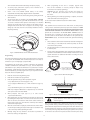
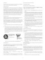
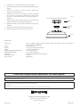
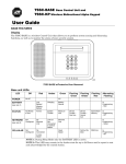
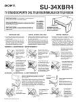
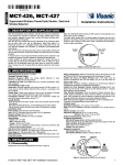
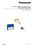
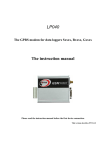
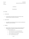
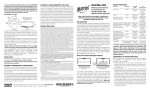
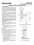
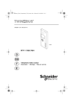
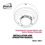
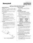
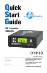
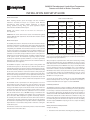
5808W3A Photoelectronic Smoke Alarm/Temperature
Detector with Built-in Wireless Transmitter
INSTALLATION AND SETUP GUIDE
General Information
Table 1: Detector LED Modes
Before installing detectors, please thoroughly read these installation
instructions and Guide for Proper Use of System Smoke Detectors
(A05-1003-002), which provides detailed information on detector
spacing, placement, zoning, wiring, and special applications. Copies
of this manual are available from Honeywell.
NOTICE: This manual should be left with the owner/user of
this equipment.
IMPORTANT: This smoke alarm must be tested and maintained regularly
following CAN/ULC S552 requirements. The smoke alarm should be cleaned
at least once a year.
General Description
The 5808W3 photoelectronic smoke/heat smoke alarm with built-in wireless
transmitter is intended for use with wireless alarm systems that support 5800
series devices. Refer to control/communicator installation instructions for
compatibility. The 5808W3A smoke alarm/heat detector can be used with
any 5800 series wireless receiver/transceiver for residential installations. For
commercial installations, the 5881ENHC or the 5883H receiver is required. The
transmitter can send alarm, tamper, maintenance (when control panels are
equipped to process maintenance signals), and battery condition messages
to the system’s receiver. The maintenance signal fully complies with the
sensitivity test requirement specified in NFPA 72, 7-2.2 and is approved by
ULC. Refer to the wireless system’s instructions for the maximum number of
transmitters that can be supported.
Green LED
Red LED
Piezoelectric
Horn
Horn
Blinks every
5 sec
Blinks every
5 sec
Off
Normal (standby)
Blinks every
10 sec
Off
Off
Out of Sensitivity
Off
Blinks every
5 sec
Off
Freeze Trouble
Off
Blinks every
10 sec
Off
Smoke Alarm
Off
Blinks every
1 sec
ON
Thermal Alarm
Off
Blinks every
4 sec
ON
Low Battery
Off
Blinks every
45 sec
Chip every 45
sec after LED
blinks for 7 days
During initial power-up, the red and green LEDs will blink synchronously once
every 5 seconds. It will take approximately 20 seconds for the smoke alarm to
finish the power-up cycle (see Table 1).
After power-up has completed and the smoke alarm is functioning normally
within its listed sensitivity range, the green LED blinks once every 10 seconds.
If the smoke alarm is in need of maintenance because its sensitivity has shifted
outside the listed limits, the red LED blinks once every 5 seconds. When alarm
has been activated by smoke, the red LED blinks every 1 second. During a
thermal alarm condition (>135°F) the red LED blinks once every 4 seconds. The
LED indication must not be used in place of the tests specified under Testing.
In a freeze trouble condition, the red LED will blink once every 10 seconds
(refer to Table 1). If the smoke alarm senses a low battery condition, the red
LED blinks once every 45 seconds.
The 5808W3A incorporates a state-of-the-art optical sensing chamber and
an advanced microprocessor. The microprocessor allows the smoke alarm to
automatically maintain proper operation at factory calibrated detection levels,
even when sensitivity is altered due to the presence of contaminants settling
into the unit’s smoke chamber. In order for this feature to work properly, the
chamber must never be opened while power is applied to the smoke alarm.
This includes cleaning, maintenance or screen replacement. All models also
feature a restorable, built-in, fixed temperature (135°F) thermal detector and
is also capable of sensing a pre-freeze condition if the temperature is below
41°F.
To measure the smoke alarm’s sensitivity, the i3 Series Model CSENS-RDRA
Infrared Sensitivity Reader tool (see Figure 4) should be used. Refer to
instruction manual D100-98-00 for proper use of the CSENS-RDRA.
The 5808W3A contains a piezoelectric horn which generates a tone in an
alarm condition. In alarm, a message is also sent to the wireless control panel
and the smoke alarm’s zone number is displayed at the console. The alarm
message is transmitted every 4 seconds until the smoke or heat condition has
cleared and the smoke alarm has reset. During an alarm condition, pressing
the alarm’s test switch will silence the piezoelectric horn for 5 minutes.
Once the smoke alarm has reset, a RESTORE message is transmitted to the
control panel and the transmitter’s zone number can be cleared from the
panel. The built-in Drift Compensation algorithm automatically maintains
the sensitivity of the smoke alarm. Once the smoke alarm reaches its limit of
compensation, it transmits a maintenance signal to the panel. The mounting
base installation is simplified by the incorporation of features compatible with
drywall fasteners or other methods that provide a method for securing the
smoke alarm in place.
Low Battery Detection
The 5808W3A is powered by a single 3-volt CR123A or DL123A Lithium battery
(included). The smoke alarm checks for a low battery at least every 65 minutes.
If a low battery is detected, the transmitter sends a low battery message to
the control panel, which beeps and displays the detector’s zone number. In
addition, the red LED of the 5808W3A will blink every 45 seconds and the test
switch will be disabled. This condition will exist for a minimum of 7 days, and
then the smoke alarm’s horn will “chirp” about every 45 seconds. Pressing the
test switch during this time will silence the chirps for 12 hours. The battery
should be replaced BEFORE the chirps begin. Be sure to replace the battery
with a fresh one.
Battery Installation and Replacement
Two LEDs and a sounder on the smoke alarm provide local visual and audible
indication of the smoke alarm’s status:
To replace the battery:
1.Remove the smoke alarm from its mounting base by twisting the smoke
-1-
alarm counterclockwise. Remove the battery, and dispose properly.
8.When programming for this zone is complete, program other
zones for the transmitter as necessary (except for Tamper Loop
4, which does not require programming).
2.To ensure proper power-down sequence, wait a minimum of 20
seconds before installing new battery.
WARNING: The fire protection zone enrolled must always be
Loop 1. Otherwise, fire annunciations will not be reported by
the control.
3.Install a new 3-volt CR123A Lithium battery in the battery
compartment. Follow the polarity diagram inside the compartment.
4.Reinstall the smoke alarm onto the mounting base by turning the smoke
alarm clockwise.
9.Exit Programming mode when programming is complete, and test the
smoke alarm. Refer to the Testing Section.
5.Test the smoke alarm as described in the TESTING SIGNAL STRENGTH
section of this manual. The green LED should blink about once every
10 seconds to indicate normal operation. If the battery is not installed
correctly, the smoke alarm will not operate and the battery may be
damaged. If the smoke alarm does not appear to be sending a signal
during any of the tests, check for correct battery installation and for a
fully charged battery.
See the control unit’s installation instructions for further details.
Mounting
First, determine the best location for the smoke alarm, one that provides
a strong wireless transmission path and proper smoke detection. A GOOD
TRANSMISSION PATH MUST BE ESTABLISHED FROM THE PROPOSED MOUNTING
LOCATION BEFORE PERMANENTLY INSTALLING THE SMOKE ALARM. To check,
perform the test described in the TESTING SIGNAL STRENGTH section of
this manual. Prior to mounting the smoke alarm to the mounting base,
you must “enroll” the smoke alarm’s serial number into the system (see the
PROGRAMMING section). To mount the smoke alarm, perform the following
steps:
Test Switch
1.Once a suitable location has been determined, install the mounting base
on the ceiling or on the wall (if local ordinances permit). Use the two
screws and anchors provided.
Green LED
2.Turn the smoke alarm in a clockwise direction in the mounting base until
it clicks into place.
Red LED
S0289-00
3.Test the smoke alarm immediately after completing the installation (as
described in the TESTING section of this manual) and refer to the control
system’s instructions for additional information concerning the use of
wireless smoke alarms.
Figure 1. 5808W3A Wireless Smoke Alarm/Heat Detector
Programming
The smoke alarm must be enrolled in the control panel before it can operate
in the system. The 5808W3A smoke alarm/heat protection zone must be
enrolled as Loop 1 and “Input Type” 3 (supervised RF).
Direct Mount Holes
If programmed, this smoke alarm is capable of monitoring the additional
conditions of Maintenance (transmitted as Loop 2), and Low Temperature
(transmitted as Loop 3). Tamper is transmitted as Loop 4, but does not require
programming. To take advantage of the value added features of Maintenance
and Low Temperature, you must program each loop as a separate zone in the
5800 series wireless compatible panel.
1.
Enter the control’s Zone Programming mode.
2.
Enter the zone number to be programmed.
3.
Enter the applicable zone type when prompted. Program
• Loop 1 (Heat/Smoke) as a Fire zone (type 9 or 16),
• Loop 2 (High/Low Maintenance) as a 24-Hr. Trouble zone (type 19),
and
• Loop 3 (Freeze Warning Sensor) as a 24-Hr. Aux. zone (type 8).
Tamper
Release Tab
Tamper Resistant Tab
(Cut off small tab activate
to
tamper resist feature)
S0290-00
Figure 2. Smoke Alarm Mounting Base
NOTE: Loop 2 High/Low Maintenance is supported only on commercial
control panels such as the Vista-128FBP.
S0162-01
4.When prompted, enter Input Type 03 (3 on some controls)
– Supervised RF Transmitter.
Figure 3. Mount Smoke Alarm Across Ceiling Panel Support
5.When prompted for the serial number, transmit from the smoke alarm
by activating the tamper switch. To do this, hold the base of the smoke
alarm in one hand, and rotate the smoke alarm counter-clockwise on
the base until it snaps open. Then return to clockwise position until the
smoke alarm snaps into place.
DO NOT attach the smoke alarm to removable ceiling
panels. Attach the smoke alarm across panel support as
shown in Figure 3.
Dust covers are an effective way to limit the entry of dust into the smoke alarm
sensing chamber during construction. However, they may not completely
prevent airborne dust particles from entering the smoke alarm. Therefore, it is
recommended that the detectors be removed before beginning construction
or other dust producing activity. When returning the system to service, be sure
to remove the dust covers from any detectors that were left in place during
6.When the serial number is displayed, transmit from the smoke alarm a
second time by activating the tamper switch again as described in Step
5. The current loop number (4) will begin to flash.
7.Manually change the loop number to the desired loop number for
the zone (according to the application).
-2-
construction.
alarm still fails to activate, return for repair.
Smoke alarms are not to be used with detector guards unless the combination
has been evaluated and found suitable for that purpose.
Testing Signal Strength
NOTE: Remove battery tab before installation.
Tamper Protection
This test should be performed in accordance with NFPA 72 inspection,
testing and maintenance requirements to determine a strong
communication path with the control panel.
This smoke alarm has a built-in tamper switch that will cause a CHECK signal
to be displayed at the console of the alarm system if it is removed from its
mounting base. The 5808W3A smoke alarm includes a tamper-resistant
feature that prevents removal from the mounting base without the use of a
tool. To engage the tamper-resistant feature, cut the small plastic tab located
on the mounting base (Figure 2), and then install the smoke alarm. To remove
the smoke alarm from the base once it has been made tamper resistant, use
a small screwdriver to depress the square tamper release tab, located on the
skirt of the mounting base, and turn the smoke alarm counterclockwise.
1.Activate the wireless system’s GO/NO GO TEST mode from the
keypad.
2.Depress and hold the smoke alarm’s TEST switch. If the smoke alarm has
not previously detected a low battery condition and it is within proper
sensitivity limits, the smoke alarm should immediately transmit an alarm
signal to the control panel. The built-in horn will start to sound about 2.5
seconds after depressing the button.
Testing the Sensor
3.The wireless system’s keypad should emit at least three audible
sounds when the alarm transmission is received and will display
the transmitting detector’s zone number.
NOTE: Before testing, notify the central station that the smoke alarm system is
undergoing maintenance, in order to prevent unwanted alarms.
4.When the console has received the test signal, release the TEST switch.
The horn will immediately stop and a few seconds later the smoke alarm’s
zone number will clear from the console display.
During initial power-up, do not use CSENS-RDRA or canned smoke to test the
detector. The CSENS-RDRA and canned aerosol can be used after power-up
sequence has completed. Smoke Alarms must be tested after installation and
following periodic maintenance. The 5808W3A may be tested as follows:
5.If the console does not respond as noted, check the polarity of the
battery and be sure it is fresh. If this is an initial installation, try moving
the smoke alarm to another location that provides proper reception. Also
be sure that the smoke alarm has been “enrolled” by the control panel
(see PROGRAMMING). Then, repeat the test.
A. Test Switch
1.A recessed test switch is located on the smoke alarm housing (see Figure
4).
6.Turn off the system’s TEST mode from the keypad (security
code + OFF).
2.Push and hold the recessed test switch for a minimum of 5 seconds. Use
a small screwdriver or Allen key with maximum diameter of 0.18 inch (the
alarm panel will trigger and then the smoke alarm will go into alarm. If
the tool is removed from the recessed switch the sounder will shut off.)
Testing Programmed Loops
This test should be performed before installation to ensure that all
loops intended to be used have been programmed and are operational
in the system.
If the smoke alarm is within the listed sensitivity limits, the LED on the
smoke alarm should blink once per second and the horn should sound
within 3 seconds.
1.Activate the system’s TRANSMITTER ID SNIFFER mode from the keypad
(see the control panel’s instructions). All programmed wireless zones will
be displayed, one by one, on the system keypad. Make sure all smoke
alarm zones are displayed in the sequence. (If they are not, recheck that
all zones have been properly programmed.)
POSITION CSENS-RDRA AT AN
ANGLE ON THE OVAL AREA OR
AT THE CHAMBER OPENING BY
THE WORD “PAINT”
2.With the smoke alarm mounted to the bracket, press the smoke alarm’s
TEST switch. All zones associated with the smoke alarm should disappear
from the keypad on the next display cycle. This means that the system
has received a transmission from each loop you programmed.
RECESSED TEST SWITCH
PUSH RECESSED
SWITCH WITH A 0.18˝
MAX. DIAMETER TOOL
LED
S0308-00
3.When testing is complete, enter the Installer code + the OFF key
to exit TEST mode.
Figure 4. Recessed Test Switch Opening and CSENS-RDRA Position
B. Smoke Entry Test
When all system testing has been completed, notify the central station that
the system is back on line.
Hold a smoldering punk stick or cotton wick at the side of the smoke alarm
and gently blow smoke through the smoke alarm until the unit alarms.
Canned aerosol is also an acceptable method.
Maintenance
NOTE: Before performing maintenance on the smoke alarm, notify the proper
authorities and the central station that maintenance is being performed and
the system will be temporarily out of service. Disable the zone or system
undergoing maintenance to prevent any unwanted alarms. Power must be
removed from the smoke alarm before performing maintenance of any kind
by removing the smoke alarm’s battery.
C. Direct Heat Method (Hair dryer of 1000-1500 watts)
Direct the heat toward either side thermistor. Be sure to hold the heat source
about 12 inches from the smoke alarm to avoid damage to the plastic. The
smoke alarm will reset only after it has time to cool.
Smoke detection testing
protection capability.
is
recommended
for
verifying
system
A smoke alarm that fails to activate with any of these tests should first be
cleaned as outlined in this manual’s MAINTENANCE section. If the smoke
1.To ensure proper power-down sequence, battery must be removed from
smoke alarm for a minimum of 20 seconds before removing chamber
top.
2.
-3-
Remove the smoke alarm cover by turning counterclockwise.
3.
Vacuum the cover or use canned air to remove any dust or debris.
4.Remove the top half of the screen/sensing chamber by lifting straight up
(Figure 5).
5.Vacuum or use canned air to remove any dust or particles that
are present on all chamber sections.
6.Replace the top half of the screen/sensing chamber by aligning
the arrow on the screen/sensing chamber with the arrow on the
housing. Press down firmly until the screen/sensing chamber is
fully seated.
S0111-00
Figure 5. Removing Screen/Sensing Chamber
7.Replace the smoke alarm cover by placing it over the screen/sensing
chamber and turning it clockwise until it snaps into place.
REMOVABLE
COVER
8.Reinstall the battery into the battery compartment noting proper
orientation.
9.
SCREEN/SENSING
CHAMBER
(TOP HALF)
Reinstall the smoke alarm and test. (See the Testing section.)
10. Notify the central station when the system is back in service.
HOUSING
Specifications
Power Source:One 3-volt CR123A Lithium Battery (included). (Replace with Duracell DL123A, Sanyo CR123A,
Panasonic CR123A or ADEMCO 466.)
Height:
2.3 inches (58 mm)
Diameter:
5.3 inches (135 mm) with mounting base
Weight:
8.5 oz. (241 g) without battery
Operating Ambient Temperature Range:
32° to 100°F (0° to 38°C)
Operating Humidity Range:
0% to 95% Relative Humidity
Heat Sensor:
135° F Fixed Temperature Electronic Thermistors
Freeze Warning Sensor:
41°F (5°C)
Agency Listings:
CAN/ULC S531
Please refer to insert for the Limitations of Fire Alarm Systems
FOR WARRANTY INFORMATION AND FOR DETAILS REGARDING THE LIMITATIONS OF THE ENTIRE ALARM SYSTEM, REFER TO THE INSTALLATION INSTRUCTIONS FOR THE
RECEIVER/CONTROL WITH WHICH THIS DEVICE IS USED.
This device complies with Part 15 of the FCC rules and RSS210 of Industry Canada. Operation is subject to the following two conditions: (1) This device may not cause harmful interference, and (2) This device
must accept any interference received, including interference that may cause undesired operation.
ID# 573F-5808W3
The user shall not make any changes or modifications to the equipment unless authorized by the Installation Instructions or User’s Manual.
10 Whitmore Rd., Woodbridge, ON, L4L 7Z4
Copyright © 2006 Honeywell International Inc.
www.honeywell.com/security
D100-100-00
- 4 -
I56-3062-000