1
m
INTERBUS-S
co
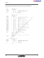
User Manual for INTERBUS-S
IBS S5 DCB UM E
Revision:
B
Order No.:
27 58 36 3
in
ec
om
Type:
po
ne
nt
s.
Controller Board for Siemens SIMATIC S5
on
l
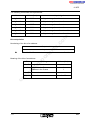
This user manual is valid for:
IBS S5 DCB/I-T
IBS S5 DCB-T
IBS S5 SWD
IBS SYS SWT
Order No.: 27 58 15 6
Order No.: 28 06 22 8
Order No.: 27 80 88 1
Copyright by Phoenix Contact 04/1994
5003B
Firmware ≥ 3.5
Hardware revision ≥C
Software ≥ 2.2
Software ≥ 2.3
m
co
s.
nt
ne
po
om
in
ec
on
l
We are constantly attempting to improve the quality of our manuals.
Should you have any suggestions or recommendations for improvement of the contents and
layout of our manuals, we would appreciate it if you would send your recommendations to:
Phoenix Contact GmbH & Co.
Abt. Applikation/Techn. Dokumentation
Flachsmarktstraße 8 – 28
32825 Blomberg
Germany
5003B
(
*49-5235-550
*49-5235-55-1200
Please Read Completely
Please read completely before reading this manual !!
In order to guarantee that your use of this manual is as straightforward as possible and that
hardware is used safely in the installation, operation and maintenance phases, we request
that you carefully read and observe the following instructions:
Explanation of Symbols Used
nt
s.
co
m
The "attention" symbol refers to erroneous handling, which could lead to
damage to the hardware or software, or in indirect connection with dangerous
process peripherals (e.g., unprotected shafts or motors with actuator functions)
to light to severe personal injury. The symbol is always located to the left of the
tagged text.
om
po
ne
The "pointer" hand gives you tips and advice on the efficient use of hardware
and on software optimization, to save you from performing extra work, for
example. In addition, text marked in this way informs you of system-related
conditions that must absolutely be observed to achieve error-free operation.
The hand is also found in front of clarifications of terms.
in
ec
Statement of Legal Authority
on
l
This manual, including all illustrations contained herein, is copyright protected. Use of this
manual by any third party in departure from the copyright provision is forbidden.
Reproduction, translation, or electronic or photographic archiving or alteration requires the
express written consent of Phoenix Contact. Violations are liable for damages.
Phoenix Contact reserves the right to make any technical changes that serve for the purpose
of technical progress. Phoenix Contact reserves all rights in the case of a patent award or
listing of a registered design. External products are always named without reference to
patent rights. The existence of such rights shall not be excluded, however.
The use of products described in this manual is oriented exclusively to qualified electricians
or persons trained in the electrical field, who are entrusted with the applicable national
standards. Phoenix Contact assumes no liability for erroneous handling of or damage to
Phoenix Contact or external products resulting from disregard or information contained in
this manual.
5003B
5003B
s.
nt
ne
po
om
in
ec
on
l
co
m
Supplementary Notes (February 1996)
Supplementary Notes
IBS S5 DCB UM E, Order No.: 27 58 36 3, Revision B
Although the manual was thoroughly checked, some additions became necessary after its
publication. Please observe the following notes.
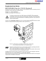
Chapter 7.2, “Cable Installation”:
InterBus was designed for industrial use.
m
To fulfill the requirements of the EMC directive 89/336/EEC (Electromagnetic
Compatibility) and the listed harmonized European standards, the following specifica-tions are to be observed besides the installation guidelines in the relevant manuals and Data Sheets.
on
l
in
ec
om
po
ne
nt
s.
co
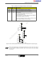
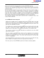
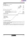
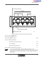
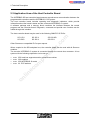
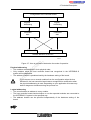
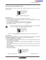
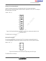
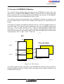
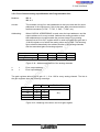
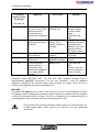
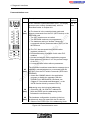
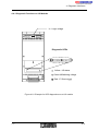
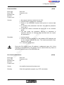
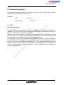
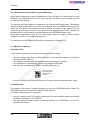
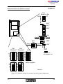
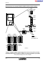
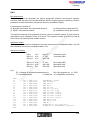
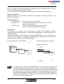
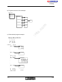
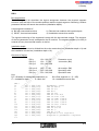
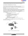
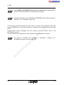
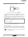
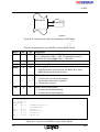
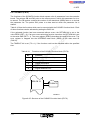
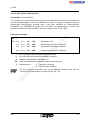
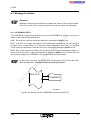
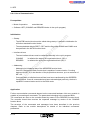
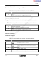
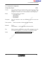
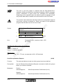
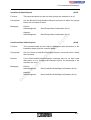
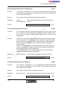
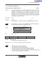
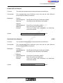
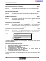
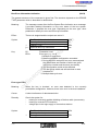
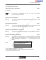
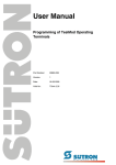
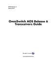
Connect, in the immediate vicinity (max. 25 cm) of the controller board, the remote bus cable
shield to the equipontential bonding conductor (see figure below).
50010010
Figure C1: Example for grounding the shield with a metal clamp
(The controller board shown is of no specific type!)
Expose the braided shield only over the length required for grounding the shield,
without causing damage to the braid or the signal lines!
Use a metal clamp that fits the diameter of your remote bus cable, which ensures
a secure connection while not squeezing the cable!
InterBus devices with the degree of protection IP20 and lower must be installed in electrical
equipment rooms or in closed cabinets (e.g. metal switch cabinets).
When installing controller boards and slave boards, please observe also the PLC and computer
manufacturers’ installation instructions!
5003BC04
1
Supplementary Notes (February 1996)
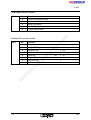
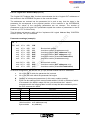
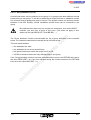
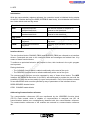
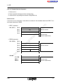
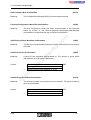
Chapter 6, “Startup”:
The communication register base address settings documented in the manual do
not match the program examples on the ISFP diskette.
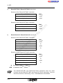
The following sections of the text (with page numbers) are affected:
Page
Section
c) Program example
6-15
d) Detailed program example with organization, function and data blocks
6-25
d) Detailed program example with organization, function and data blocks
6-28
FB210 listing
6-43
d) Detailed program example with organization, function and data blocks
6-57
d) Detailed program example with organization, function and data blocks
nt
s.
co
m
6-10
FEN3
:
KF+200 ->
FEN3
ne
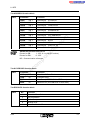
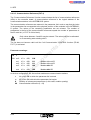
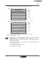
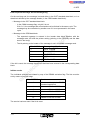
Replace the values as follows in the above text sections!
:
KF +252
Page
Section
Figure 6-6
6-12
Figure 6-8
6-22
Figure 6-9
6-26
Figure 6-10
6-40
Figure 6-11
6-54
Figure 6-12
on
l
in
ec
6-9
om
po
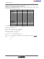
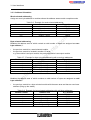
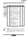
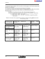
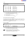
In accordance with this change, change the communication register addresses in the figures
listed in the table below (200->252; 202->254):
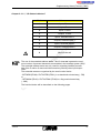
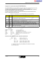
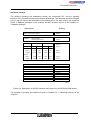
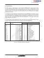
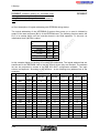
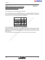
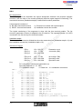
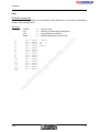
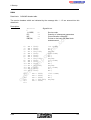
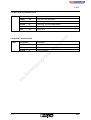
Chapter 3.1, “ID Code of the Modules”, Page 3-4, Table 3-2
All register width details are given as number of bytes.
The numbers given for the IB ST 24 DO 8/3-2A module were mixed up by mistake for the
columns "OUT-AR" and "Register width" (both numbers are given in bytes).
Correct is: OUT-AR =1 and register width = 1
The number"“81 *" for the IB ST 24 DO 8/3-2A module in the "Length code" column was given
in a hexadecimal format. The correct decimal value is "129".
The number"“1**" is of no importance.
The footnote text for both length specifications refers to firmware versions below version 3.5.
2
5003BC04
Supplementary Notes (February 1996)
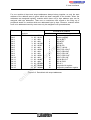
The numbers for the IBS IP CDI 1/24-F, IBS IP CDI 2/24-F, IBS IP CDO 1/24-F, IBS IP CDO
2/24-F, IB ST 24 DI 16/4 modules were given one byte too small in the “Register width” column.
The register width is 2 bytes for the above modules.
The numbers for the IB ST 24 DI 32/2 and IB ST 24 DO 32/2 modules were given two bytes
too small in the “Register width” column (both in bytes). The register width for the above modules is 4 bytes.
Chapter 3.1, “ID Code of the Modules”, Page 3-5, Table 3-3
co
m
The numbers for the InterBus-S module IBS 24 IP DIO BB1/E-T were given one byte too small
in the columns "OUT-AR" and "Register width" (both numbers in bytes). For this module the
register width is 4 bytes and the assigned output address area is 2 bytes.
s.
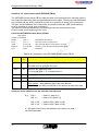
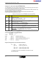
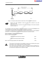
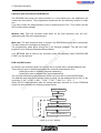
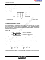
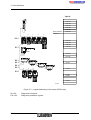
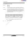
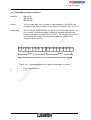
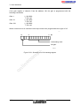
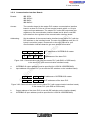
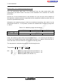
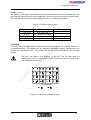
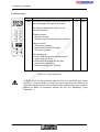
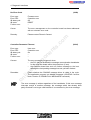
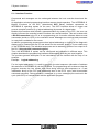
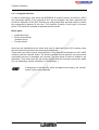
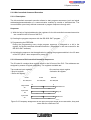
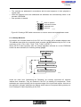
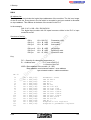
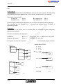
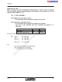
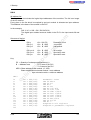
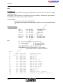
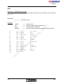
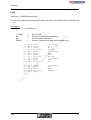
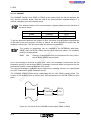
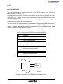
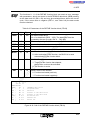
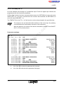
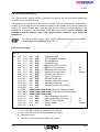
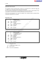
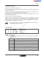
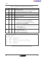
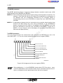
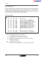
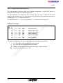
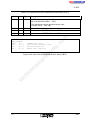
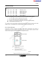
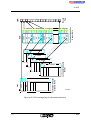
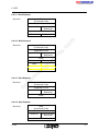
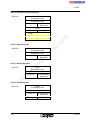
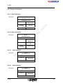
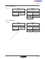
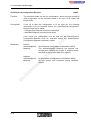
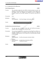
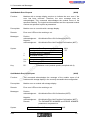
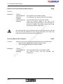
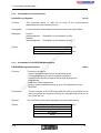
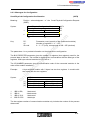
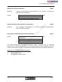
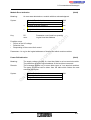
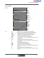
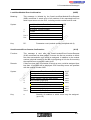
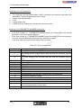
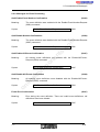
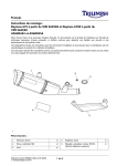
Chapter 3.5.7, "Digital Modules with 16 Inputs and 16 Outputs", Page 3-30, Figure 3-17
nt
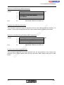
The bit designations for byte l and byte m were reversed in Figure 3-17. The correct bit
assignment is shown in the following figure.
ne
Word n
Byte n
l.7 l.6
po
n.7 n.6 n.5 n.4 n.3 n.2 n.1 n.0
l.5
Word l
Byte l
l.4 l.3 l.2 l.1 l.0
m.7 m.6 m.5 m.4 m.3 m.2 m.1 m.0 k.7 k.6 k.5 k.4 k.3 k.2 k.1 k.0
om
Byte m
Byte k
5003C310
in
ec
Chapter 6, “Bus topology for the example (DCBADR, DCBEEP, DCBZYK, DCBCP,
DCBECP)”, Pages 6-12, 6-22, 6-26, 6-40, 6-54
on
l
The addresses for the diagnostic bit register in the example diagrams on the above pages are
not “I 30.0 - I 31.7”, but “I 126.0 - 127.7”.
Chapter 6, Pages 6-51, 6-53, 6-60 and 6-62, data block designations:
The numbers in the data blocks are reversed between the Pages 51 and 53 as well as between
Pages 60 and 62.
Correct is: Pages 51 and 60 describe the data block 23 and Pages 53 and 62 describe the data
block 21.
5003BC04
3
Supplementary Notes (February 1996)
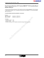
New Firmware Revision V3.71 for the
IBS S5 DCB (/I)-T Controller Board for SIMATIC S5 PLCs
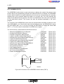
Owing to functional extensions, technical improvements and corrections in the firmware, there
are some innovations for the IBS S5 DCB (/I)-T controller boards for SIMATIC S5 PLCs.
Controller boards and documentation concerned:
Hardware:
IBS S5 DCB/I-T:
IBS S5 DCB-T:
3.5x
3.71
po
The firmware can be updated as of:
- Firmware version: 3.3x
ne
nt
s.
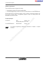
Upgrade:
A hardware upgrade with the update version is possible with:
- Hardware version: IBS GB S5 9166835 C
- Plug-on board type: MA5
co
Firmware:
- Previous version:
- Update version:
m
Order No.: 27 58 15 6
Order No.: 28 06 21 5
on
l
in
ec
om
User manuals:
German:
IBS S5 DCB UM (Order No.: 28 06 23 1)
English:
IBS S5 DCB UM E (Order No.: 27 58 36 3)
4
5003BC04
Supplementary Notes (February 1996)
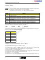
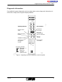
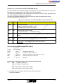
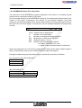
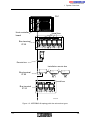
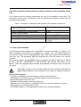
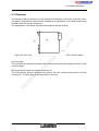
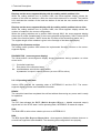
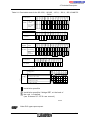
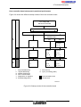
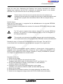
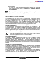
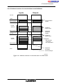
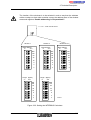
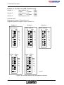
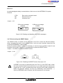
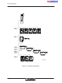
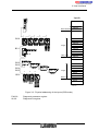
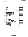
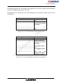
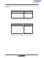
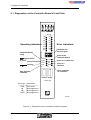
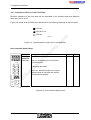
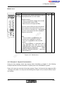
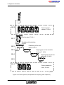
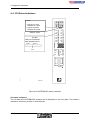
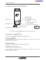
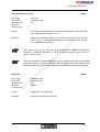
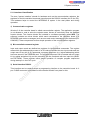
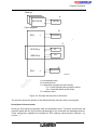
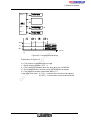
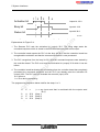
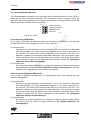
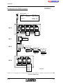
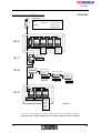
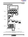
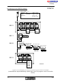
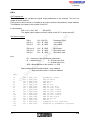
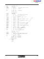
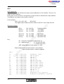
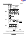
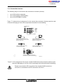
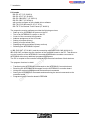
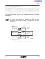
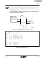
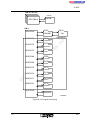
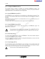
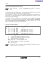
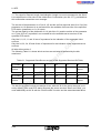
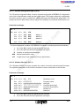
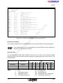
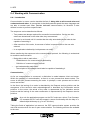
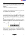
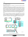
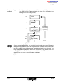
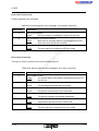
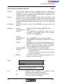
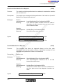
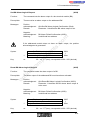
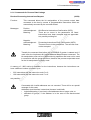
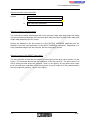
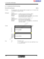
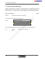
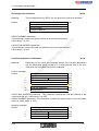
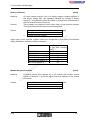
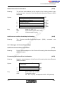
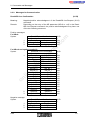
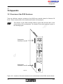
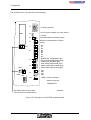
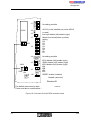
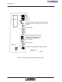
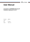
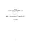
Diagnostic Information
For InterBus-S system diagnostics, the front plate makes various diagnostic information via
LEDs and a 3-digit seven-segment display available.
00 11 33 44
MODE
ADDRESS
MODE
ADDRESS
9/1
9/1
10/2
10/2
Operating indicators:
5/5
5/5
6/6
6/6
15/7
15/7
7/7
7/7
Error indicators:
Parameter for
the error type
nt
READY
READY
CTRL
CTRL
BASP
BASP
RB
RB
ne
INTERBUS running
RUN
RUN
LB
LB
BSA
BSA
MOD
MOD
om
Error in a
local bus
X3
X3
po
X2
X2
Error in a remote bus
REMOTE
REMOTE
Error message
of a module
RS
232
RS 232
RESET
RESET
Parameter
in
ec
Error type
13/5
13/5
14/6
14/6
Error in the
controller board
BASP signal of PLC
is active
(At least one)
bus segment
disabled
3/3
3/3
4/4
4/4
s.
Controller board
ready
11/3
11/3
12/4
12/4
m
8/0
BYTE
BYTE
n+1
n+1
0/0
0/0
1/1
1/1
2/2
2/2
co
nn
8/0
Error code
on
l
Local bus
Remote bus
Local bus
segment number
5003B401
5003B401
Figure 1: Operating and error indicators on the front plate
5003BC04
5
Supplementary Notes (February 1996)
CTRL (Controller Error)
LED description
- Red LED
- Parameterization error on the controller board or in the software parameterization
Parameter
- Hexadecimal value
- Error description in the user manual
co
m
RB (Remote Bus Error)
LED description
- Red LED
- Wrong remote bus segment consisting of a BK module and the preceding remote bus cable
Parameter
- Decimal value
- No. of the bus segment concerned
om
po
ne
nt
s.
LB (Local Bus Error)
LED description
- Red LED
- Wrong local bus segment consisting of the individual local bus modules and the connecting
bus cables
Parameter
- Decimal value
- No. of the bus segment concerned
on
l
in
ec
MOD (Module Error)
LED description
- Red LED
- Defective module periphery
- I/O voltage failure
- Short-circuit at the output
- Only for devices with status message
Parameter
- Decimal value
- No. of the bus segment concerned
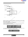
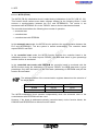
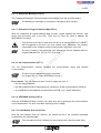
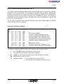
RB and LB (Indication of the error location by specifying an area)
LED description
- Red LED
Parameter
- Decimal value
- The parameter specifies the base bus segment number of the area concerned.
- Group error messages with the error codes E01, E02, E04, E05 and E06
- The error was assigned to a bus area which may consist of several bus segments.
6
5003BC04
Supplementary Notes (February 1996)
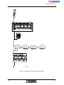
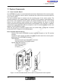
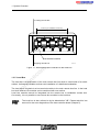
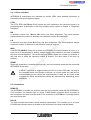
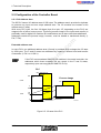
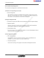
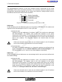
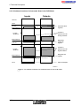
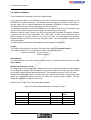
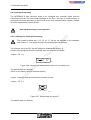
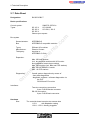
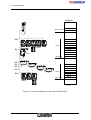
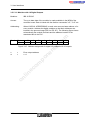
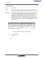
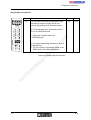
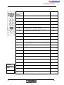
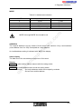
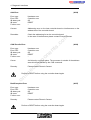
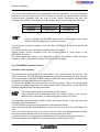
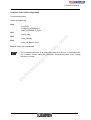
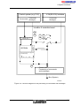
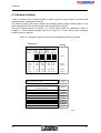
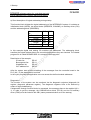
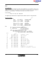
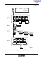
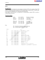
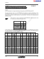
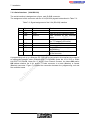
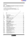
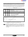
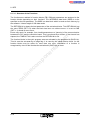
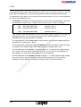
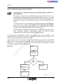
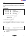
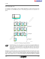
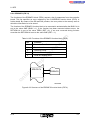
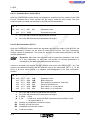
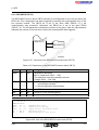
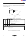
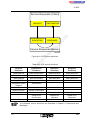
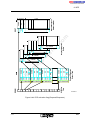
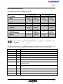
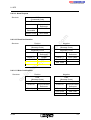
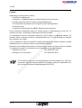
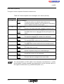
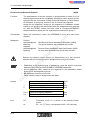
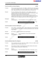
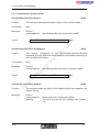
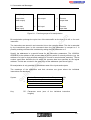
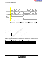
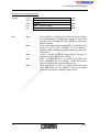
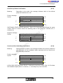
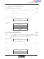
Table 1: Indication of the diagnostic data on the front plate
LB - LED
RB - LED
Description
on
off
Error in the displayed local bus segment
off
on
Error in the displayed remote bus segment
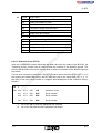
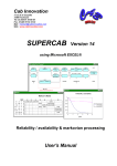
on
on
See Figure 2,
the error cause is limited to the branch of the:
1) preceding remote bus
2) preceding IB ST compact station/local bus segment
3) preceding installation remote bus
on
l
in
ec
om
po
ne
nt
s.
co
m
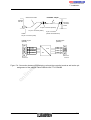
and the bus segment whose number is shown on the
seven-segment display of the front plate.
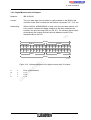
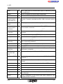
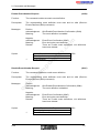
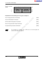
Figure 2: Error location (dashed area) with respect to the displayed bus segment (gray)
When logical addressing is used (physical addressing is shown here!) the order of
the bus segment numbers may differ from the one shown here (see System
Description).
5003BC04
7
8
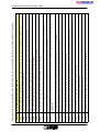
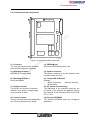
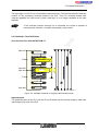
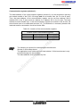
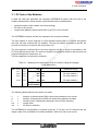
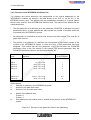
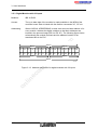
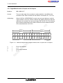
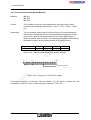
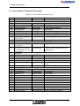
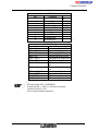
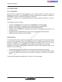
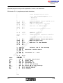
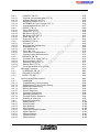
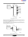
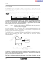
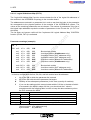
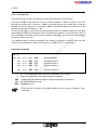
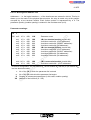
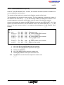
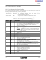
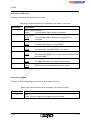
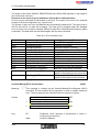
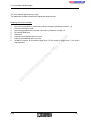
The ID of a BK does not agree with the one of the original configuration (e.g. due to a device replacement or device error).
DD01
LB is longer than expected because a module was added during operation.
LB is shorter than expected because a module was removed during operation.
In the specified LB a module ID code is not identical with that in the original configuration.
DD04
DD05
DD06
LB is at the wrong position in the bus system, because the LB was connected to a free BK module of the initial configuration.
Bus segment is missing or the remote bus cable is open (no or defective remote bus cable connection).
Too many transm. errors (corresponds to error type EE06, no error when configuration was acquired and compared) between two error-free
data cycles.
Configuration longer than expected because the remote bus was extended compared with the initial configuration.
DD08
DD09
DD0A
DD0B
Wrong process data length or data register of a bus device is defective (remote bus).
Wrong process data length or data register of a bus device is defective (local bus).
DD11
DD12
Temporary bus interrupt, voltage reset or jumper in the outgoing remote bus defective.
Like DD0A, but in the additional diagnostic phase.
DD1A
DD42
Bus interruption or voltage reset in the additional diagnostic phase.
DD19
Like DD0B, but in the additional diagnostic phase.
Temporary error in a LB using 8-wire technology during operation caused by a cable and/or module error (similar to DD03/05/08).
DD18
DD2B
Temporary change of an ID code during operation with specified BK or module in specified LB (similar to DD01/02/06).
DD15
n
o
Maximum configuration exceeded, the number of bus modules or of the register positions is too high.
DDOC
c
e
il n
m
o
o
p
Configuration could not be read in because the bus system was not connected.
DD07
e
n
t
n
LB is missing or open LB cable (no or defective connection between a BK and the 1st LB module or two LB modules).
DD03
c
.
s
Error description like the DD01, but related to a BK I/O.
DD02
m
o
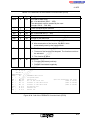
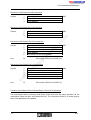
Error description (local bus, short: LB)
Error no.
Extension and improved explanations of the error numbers for the error type EE03, "Bus-Error-Information-Indication", Page 9-56
Supplementary Notes (February 1996)
5003BC04
Supplementary Notes (February 1996)
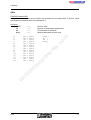
Chapter 3.1, "ID Code of the Modules", Page 3-4, Table 3-2
With the firmware update V3.71 the new IBS IP KES A/4 IN module is assigned to the ID code
23 hex.
This has the following consequences:
- The messages "battery" and "power fail" are not used for the motor relay module.
- The I/O data is processed byte-by-byte.
- The inputs and outputs of a bus terminal module can be switched off.
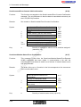
As of firmware 3.71, IBS devices with a process data length of 26 words are supported. These
devices have a length code of 17dec in the more significant byte of the ID word.
nt
s.
co
m
Chapter 8.3.3, Function block EVENT (FB 76), Page 8-85, valid as of ISFP version 2.3:
The following features were implemented for the event processing:
- Comparison of an input with a given pattern
- Counting of the occurred events in the associated event counters
- Suppression of event indications
- Readout of the event counters
Event processing is only possible with digital IBS modules.
om
po
ne
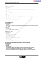
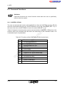
Chapter 2.3.1.1, "I/O Status Indicators", Page 2-5 ff., Mode 9 settings
Besides the familiar direct error indication with the red LEDs CTRL, RB, LB, MOD and the
associated parameters on the diagnostic front plate, firmware 3.71 includes further service
information. This service information can be accessed with the switch setting MODE 9 and an
associated address. The associated data is displayed via the three-position diagnostic display.
Note: MODE 9 must be used for service purposes only.
on
l
in
ec
Table 3 summarizes the data shown on the front plate.
5003BC04
9
Supplementary Notes (February 1996)
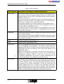
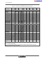
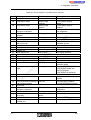
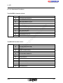
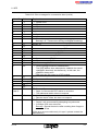
Table 3: Mode 9 settings
Description of the display (7-segment display/LEDs)
9180 - 918x
Displays the module numbers of the ten modules with the greatest number of errors on the seven-segment display (9180 = the module with the
greatest number of errors, 9181 = the module with the second greatest
number of errors, etc.)
If there are less than 10 modules to which errors can be assigned, ’Ad’
appears on the free positions. The module number ’FF’ shows special
CRC errors. In addition, all I/O data LEDs light up.
The hundred’s place of the module numbers is also mapped onto the
I/O data LEDs. LED 0 lights up for the module numbers 0-99, LED1 for
100-199, LED2 for 200-299 and so on.
This setting of the code selector switch corresponds to the result of the
Send-Located-Error-Counter (0109hex) or Send-Located-Error-CounterV24 (010Ahex) services.
9190-9199
Displays the local bus numbers of the last 10 module status errors on the
seven-segment display.
This setting of the code selector switch corresponds to the result of the
Send-Last-Module-Status-Error (010Bhex) or Send-Last-Module-StatusError (010Chex) services.
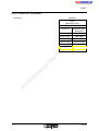
9200
Firmware revision (371 for version 3.71)
9210
Supplementary error message DDxx
9300 - 93xx
An input and an output word are reserved in the PLC’s memory with the
help of the special ID code 0015hex. The content of the output word
appears on the yellow I/O LEDs when the selector switches are set to
93XX. Also, the value XX (decimal, value range 0-99) appears in the
defined input word.
When the configuration is specified, the special ID code 0015hex is
attached to the actual configuration by means of the Check-PhysicalConfiguration (0058hex) service. It may occur only once in the
configuration specification. By means of logical addressing the two
words can be placed on any address in the PLC memory.
on
l
in
ec
om
po
ne
nt
s.
co
m
Switch position
94xx - 99xx
10
The selector switch settings 9400 to 9912 display the ID codes of the
current configuration in their physical order as hexadecimal values on
the seven-segment display. The first position 9400 provides the number
of modules of the current configuration. If there are more than 255
modules (greater than FFhex), the point of the right digit of the sevensegment display lights up for the third hex position. This code selector
switch setting corresponds to the result of the Send-Actual-Configuration
(010Dhex) or Send-Actual-Configuration-V24 (010Ehex) services.
5003BC04
Supplementary Notes (February 1996)
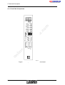
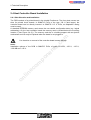
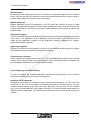
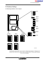
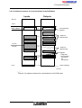
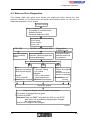
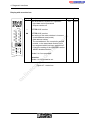
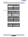
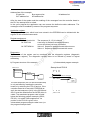
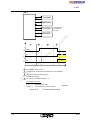
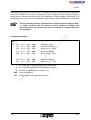
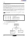
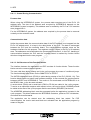
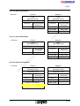
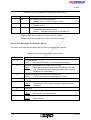
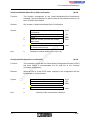
Statistical Diagnostics
Automatic enabling of the statistical diagnostic functionality
The statistical diagnostic functionality is enabled automatically with every start command.
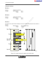
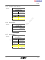
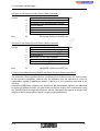
Display of the diagnostic status on the controller board
Remark
Bus active
Invalid address setting
on the controller board
Bus active
Run status of the
controller board
Bus active
Invalid address setting
on the controller board
Statistical diagnostics active
Run status of the
controller board
Statistical diagnostics active
s.
Statistical diagnostics inactive
nt
Statistical diagnostics inactive
5044AC01
om
po
Bus active
Diagnostic status
co
Bus status
ne
7-segment
display
m
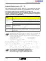
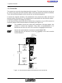
When InterBus-S is active, a disabled statistical diagnostic functionality is shown with a
bracket symbol in the left field of the three-position seven-segment display on the controller
board. The exact representation can be taken from the following figure.
in
ec
Part 1: Writing the Diagnostic Data to the Parameterization Memory
(e.g. EEPROM or S-RAM)
(Part 2 for firmware version 3.72, see Page 14)
on
l
The diagnostic data is always transferred into the EEPROM when transmission errors cause
the stop of the bus. The data remains stored in the EEPROM until it is overwritten by further
transmission errors.
The EEPROM data can be read out with the Send-Test-Parameter command, when bit 8 is
set for the selection. If there is no EEPROM, a negative confirmation is returned in which the
parameter error type is 02hex.
If an error occurs when the data is written, the EEPROM-Write-Error is reported. If there is no
EEPROM available when the data is written there will be no error message.
5003BC04
11
Supplementary Notes (February 1996)
New Firmware Revision V3.72 for the IBS S5 DCB (/I)-T Controller
Board for SIMATIC S5 PLCs
Owing to functional extensions, technical improvements and corrections in the firmware, there
are some innovations for the IBS S5 DCB (/I)-T controller board for SIMATIC S5 PLCs.
Controller boards and documentation concerned:
Order No.: 27 58 15 6
Order No.: 28 06 21 5
m
Firmware:
- Previous version: 3.71
- Update version: 3.72
po
IBS S5 DCB UM (Order No.: 28 06 23 1)
IBS S5 DCB UM E (Order No.: 27 58 36 3)
on
l
in
ec
User manuals:
German:
English:
om
The firmware can be updated as of:
- Firmware version: 3.3x
ne
nt
s.
Upgrade:
A hardware upgrade with the update version is possible with:
- Hardware version: IBS GB S5 9166835 C
- Plug-on board type: MA5
co
Boards:
IBS S5 DCB/I-T:
IBS S5 DCB-T:
12
5003BC04
Supplementary Notes (February 1996)
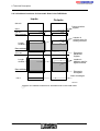
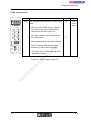
Diagnostic Performance as of FW 3.72
With firmware version 3.72 the diagnostic performance of the controller board was further
improved.This performance manifests itself when bus operation was frequently interrupted.
In this case the controller board stops bus operation and resets all outputs.
In an additional diagnostic phase, the entire bus configuration (without the controller board) is
examined. The blinking display "-||-" on the front plate and a set analysis bit in the diagnostic
register (bit 15) indicate this error analysis phase.
Meaning
co
Detection of remote bus, local bus, module errors in the bus
configuration and hardware or firmware errors on the controller board.
Detection of changes in the bus configuration
ne
Determination of temporary errors,
continuous monitoring of the bus system, in order to detect temporary
malfunctions
om
Error analysis
after a bus stop
Reset of the outputs
po
Long reset after
frequent bus
malfunctions
nt
Detection of located CRC errors
s.
Diagnotics
during operation
m
Diagnostic
phase
on
l
in
ec
Depending on the size of the bus, the error location(s) and error frequency, the
additional diagnostic phase may last from 10 seconds to several minutes.
It may be stopped with the following commands without the error message “BusError-Information” being sent:
- Alarm-Stop (004Ahex)
- Configure-Bus (0023hex)
- Group-Off (0021hex)
- Warmstart (004Chex)
- Check-Physical-Configuration (0058hex)
Depending on the PLC’s status when the bus is stopped, the BASP LED may light up
during the additional diagnostic phase.
If groups were disabled before the bus was stopped the BSA LED is also on.
After the diagnostic phase has been completed there is either an
- LED error indication (RB, LB or MOD) or, if the error cannot be located,
- E0x (x= 1,2,4,5,6) is output on the diagnostic display.
The errors indicated are ordered as with firmware revision 3.71.
For the indication by means of LEDs it is generally true that
local bus errors are only indicated if no bus errors were found.
5003BC04
13
Supplementary Notes (February 1996)
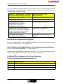
During the additional diagnostic phase some commands are only confirmed negative and will
therefore not be executed. The following table lists these commands. All commands which are
not listed will be executed as usual.
Negative messages for the
listed commands
Start-Interbus-Cycle (0001hex)
Start-Bus-Not-Possible-Con (00E3hex)
Switch-Group-On (0021hex)
Switch-Group-On-Failed-Con (80C5hex)
Set-BK-Alarm-Log (0024hex)
Reset-BK-Alarm-Log (0025hex)
Set-BK-Alarm-Phy (0026hex)
Reset-BK-Alarm-Phy (0027hex)
BK-Alarm-Failed-Con (005Ahex)
Send-Bus-Error-Information (005Ahex)
Send-Bus-Error-Information-V24 (0116hex)
Send-Localbus-Module-Error (005Bhex)
Send-All-Module-Error (005Bhex)
No-Map-Entry-Con (00EDhex)
Quit-Module-Error (0064hex)
Quit-Module-Error-All (0065hex)
Quit-Module-Error-Not-Possible-Con
(80FFhex)
ne
nt
s.
co
m
Negatively acknowledged commands
during the additional diagnostic phase
po
New Bit in the Diagnostic Bit Register
om
Bit 14 in the diagnostic-bit register is called "bus quality bit". It is set if more than 20 cycles with
errors were detected within 1 million data cycles.
in
ec
Part 2: Writing the Diagnostic Data to the Parameterization Memory
(Part 1 for firmware version 3.71, see Page 11)
on
l
Diagnostic data which describe transmission errors are only written to the parameterization
memory if there were error-free data cycles before these errors occurred.
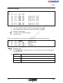
Additional Error Numbers for the Error Message
Bus-Error-Information-Indication (80C4hex)
Error No.
Error Description
DD50
Remote bus or local bus error detected in the additional diagnostic phase
DD51
Local bus error detected in the additional diagnostic phase
DD52
Remote bus error detected in the additional diagnostic phase
14
5003BC04
Supplementary Notes (February 1996)
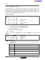
New Command: “Create-Default-CRL (012Dhex)”
Should the controller board detect PCP devices in the bus configuration after the Default-CRL
was already generated (because of the startup of the controller board or the PLC system) , this
command can be used to adapt the default communication relationship list. Afterwards the
command generates a new default communication relationship list according to the valid
configuration. The valid configuration may also be predetermined by means of logical
addressing.
m
This command is used to cancel the services “Init-Communication”,“Receive-CRLReq” and “Receive-CR-Req”, which might have been active before.
Command:
co
012Dhex
s.
Create-Default-CRL-Req
Parameter block length
0001
Result +
00 00
ne
8123hex
om
po
Create-Default-CRL-Con
nt
Positive Message:
Protocol Extension for the Bit-Controlled Command Execution
on
l
in
ec
Up to now it was possible to initiate only one command sequence in the protocol with the
associated action bit at a given point in time.
Firmware 3.72, however, allows to set several action bits, regardless of whether a command
sequence is still being processed.
The command sequences of several set action bits are processed in turn, thus from bit 0 to bit
15 and starting again with bit 0. The consequence is that still only one command sequence is
exectuted at at time.
The action bit register is evaluated if no command sequence is executed. Therefore, the setting
and clearing of the action bit during the execution of another command sequence cannot lead
to the execution of the associated command sequences.
Also - in order to have an easy to maintain program sequence - it is recommended
to initiate the command sequences one after another in order to define the
processing order.
5003BC04
15
Supplementary Notes (February 1996)
New Firmware Revision V3.73 for the IBS S5 DCB (/I)-T Controller
Board for SIMATIC S5 PLCs
Owing to functional extensions, technical improvements and corrections in the firmware, there
are some innovations for the IBS S5 DCB (/I)-T controller board for SIMATIC S5 PLCs.
Controller boards and documentation concerned:
Order No.: 27 58 15 6
Order No.: 28 06 21 5
m
Firmware:
- Previous version: 3.72
- Update version: 3.73
po
IBS S5 DCB UM (Order No.: 28 06 23 1)
IBS S5 DCB UM E (Order No.: 27 58 36 3)
in
ec
User manuals:
German:
English:
om
The firmware can be updated as of:
- Firmware version: 3.3x
ne
nt
s.
Upgrade:
A hardware upgrade with the update version is possible with:
- Hardware version: IBS GB S5 9166835 C
- Plug-on board type: MA5
co
Boards:
IBS S5 DCB/I-T:
IBS S5 DCB-T:
on
l
Changed Position of the Analysis Bit
When the firmware was updated to revision 3.73, the analysis bit in the diagnostic bit register
was shifted from position 15 to position 13.
The request of analysis bit must be adapted in PLC programs that have previously
used firmware 3.72 and this bit.
16
5003BC04
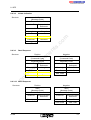
Supplementary Notes (February 1996)
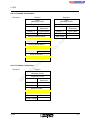
Chapter 2.3.1.1, “I/O Status Indicators”
Address area
0
Inputs, P area
1
Outputs, P area
2
Inputs, Q area
3
Outputs, Q area
4
Inputs, extended area 1
5
Outputs, extended area 1
6
Inputs, extended areas 2
7
Outputs, extended area 2
s.
co
m
Mode
Must not be set!
ne
nt
8
om
po
The use of the extended address areas 1 and 2 does not increase the maximum number of process data words connectable in the InterBus system (256)!
The extended address areas are only used for relocating InterBus process
data if the P and/or Q area would be excessively filled by other input/output
units!
The extended areas are organized by the new function blocks
in
ec
- GETINDB (FB 80) / PUTOUTDB (FB 81), in a data-block-oriented way (...DB)
or
- GETINMW (FB 82) / PUTOUTMW (FB 83) in a flag-word-oriented way
(...MW).
on
l
The function blocks will be described on the following pages.
5003BC04
17
Supplementary Notes (February 1996)
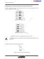
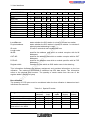
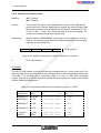
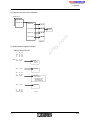
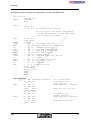
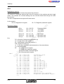
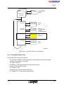
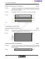
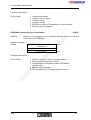
Chapter 8.3.5, new function block GETINDB (FB 80)
The GETINDB function block (FB 80) reads the data in the extended input area and copies it
to the specified data block from the specified data word onwards. The start and end addresses
are provided with the “ADR” parameter and are to be specified in words (even-numbered).
The start and end address of the output data is transferred with the “ADR” parameter and
must be specified in words (even-numbered).
The return bit indicates whether the function block has been executed error-free.
FB 80 is called at the beginning of the cycle.
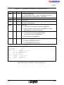
Call of the GETINDB function block (FB 80)
:SPB FB 80
s.
co
m
INTERBUS data block
Selection of the extended area
Start and end address of the data to be read
Number of the destination DB and data block
Return bit
nt
NAME :GETINDB
IBDB :
DB 9
EXT :
KF +1
ADR :
KY 0,128
DBDW :
KY 10,000
RET :
M0.2
:
Table 8-20: Parameters of the GETINDB function block (FB 80)
IBDB
DB
Description
ne
Typ
e
Number of an InterBus data block (DB 0 ... 255)
po
Name
EXT
BY
om
The data block is to be set up by you
Specifies the area to be read:
1 = extended area 1; 2 = extended area 2
BY
Start and end address of the data to be read (even values only!)
DBDW
DB
Number of the destination DB and data word (2 bytes in one data word!)
RET
BI
Return bit: 0/1 = Function executed without/with errors
Error causes: - Start address higher than end address
- Data area in the DB is insufficient for the amount of data to be read.
on
l
in
ec
ADR
Structure of the data block for the selected extended area
E.g.
DW x
DW x+1
...
DW x+126
DW x+127
= (data n), (data n+1)
= (data n+2), (data n+3)
= (data n+252), (data n+253)
= (data n+254), (data n+255)
n = first byte of the (even) start address of the data to be read,
see ADR parameter
18
5003BC04
Supplementary Notes (February 1996)
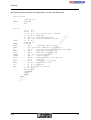
Chapter 8.3.6, new function block PUTOUTDB (FB 81)
The PUTOUTDB function block (FB 81) writes the data in the extended input area to the
extended output area determined by the “ADR” and “EXT” parameters.
The start and end address of the output data are transferred with the “ADR” parameter;
they are to be specified in words (even-numbered).
The return bit indicates whether the function block has been executed without errors.
FB 81 is called at the end of the cycle.
Table 8-21: Parameters of the PUTOUTDB function block (FB 81)
Type
IBDB
DB
Description
Number of an InterBus data block (DB 0 ... 255)
m
Name
The data block is to be set up by you
BY
Specifies the area to be read:
1 = extended area 1; 2 = extended area 2
ADR
BY
Start and end address of the data to be written (even values only!)
DBDW
DB
Number of the source DB and data word (2 bytes in one data word!)
RET
BI
Return bit of the function:
0 = Function executed without errors; 1 = Function executed with errors
ne
nt
s.
co
EXT
om
INTERBUS data block
Selection of the extended area
Start and end address of the data to be written
Number of the source DB and data word
Return bit
in
ec
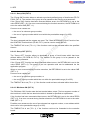
NAME :PUTOUTDB
IBDB :
DB 9
EXT :
KF +1
ADR :
KY 0,128
DBDW :
KY 10,000
RET :
M0.2
po
:SPB FB 81
on
l
Structure of the data block for the selected extended area
E.g.
DW x
DW x+1
...
DW x+126
DW x+127
= (data n), (data n+1)
= (data n+2), (data n+3)
= (data n+252), (data n+253)
= (data n+254), (data n+255)
n = first byte of the (even) start address of the data to be written,
see ADR parameter
5003BC04
19
Supplementary Notes (February 1996)
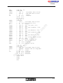
Chapter 8.3.7, new function block GETINMW (FB 82)
The GETINMW function block (FB 82) reads the data in the extended input area and copies it
to the following flag words specified from MW onwards.
The start and end addresses of the output data are transferred with the “ADR” parameter; they
are to be specified in words (even-numbered).
The return bit indicates whether the function block has been executed error-free.
FB 82 is called at the beginning of the cycle.
Table 8-22: Parameters of the GETINMW function block (FB 82)
Type
Description
IBDB
DB
InterBus data block
Number of a data block (DB 0 ... 255)
The data block is to be set up by you
EXT
BY
Specifies the area to be read:
1 = extended area 1; 2 = extended area 2
ADR
BY
Start and end address of the data to be read
co
s.
nt
Number of the destination flag word (MW) (2 bytes in one flag word)
ne
MW
BI
Return bit: 0/1 = Function executed without errors/with errors
Error causes: - Start address higher than end address
- Data area of the flags is insufficient for the volume of data to be read.
om
po
RET
m
Name
in
ec
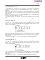
Call of the GETINMW function block (FB 82)
:SPB FB 82
NAME
:GETINMW
IBDB
:
DB 9
INTERBUS data block
EXT
:
KF
Selection of the extended area
:
:
:
KY 0,128
MW 100
M 0.2
on
l
ADR
MW
RET
+1
Start and end address of the data to be read
Number of the destination flag word
Return bit
:
Flag word assignment for the selected extended area
E.g.
MW x
MW x+2
...
MW x+126
MW x+127
= (data n), (data n+1)
= (data n+2), (data n+3)
= (data n+252), (data n+253)
= (data n+254), (data n+255)
n = first byte of the (even) start address of the data to be read
see ADR parameter
20
5003BC04
Supplementary Notes (February 1996)
Chapter 8.3.7, new function block PUTOUTMW (FB 83)
The PUTOUTMW function block (FB 83) writes the data in the specified flag word to the extended output area determined by the “ADR” and “EXT” parameters.
The start and end addresses of the output data are transferred with the “ADR” parameter and
are to be specified in words (even-numbered).
The return bit indicates whether the function block has been executed without errors.
FB 83 is called at the end of the cycle.
Table 8-23: Parameters of the PUTOUTMW function block (FB 83)
Type
Description
IBDB
DB
InterBus data block
Number of a data block (DB 0 ... 255)
The data block is to be set up by you
EXT
BY
Specifies the area to be read:
1 = extended area 1; 2 = extended area 2
ADR
BY
Start and end address of the data to be written (even-numbered values
only!)
MW
DB
Number of the source flag word (2 bytes in one flag word)
RET
BI
Return bit: 0/1 = Function executed without errors
Error cause: - Start address higher than end address
om
po
ne
nt
s.
co
m
Name
in
ec
Call of the PUTOUTMW function block (FB 83)
:SPB FB 83
NAME
:PUTOUTMW
IBDB
:
DB 9
INTERBUS data block
EXT
:
KF
Selection of the extended area
:
:
KY 0,128
MW 100
Start and end address of the data to be written
Number of the source flag word
:
M
Return bit
RET
on
l
ADR
MW
+1
0.2
:
Assignment of the flag words for the selected extended area
E.g..
MW x = (data n), (data n+1)
MW x+2= (data n+2), (data n+3)
...
MW x+252= (data n+252), data (n+253)
MW x+254= (data n+254), data (n+255)
n = first byte of the (even) start address of the data to be written,
see ADR parameter
5003BC04
21
Supplementary Notes (February 1996)
New Firmware Revision V3.75 for the SIMATIC S5 Controller Board
IBS S5 DCB (/I)-T
Owing to technical improvements of the hardware and the resulting adaptation of the firmware,
a new firmware revision, V3.75, has been introduced for the SIMATIC S5 controller boards
IBS S5 DCB (/I)-T.
Controller boards and documentation concerned:
Order No.: 27 58 15 6
Order No.: 28 06 21 5
m
Boards:
IBS S5 DCB/I-T:
IBS S5 DCB-T:
on
l
in
ec
om
po
ne
nt
s.
co
Firmware:
- Previous version: 3.73
- Update version: 3.75
- Revision marking: 13/375 (sticker at the lower edge of the front plate)
22
5003BC04
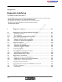
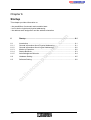
Contents
Table of Contents
System Overview ............................................................................... 1-1
1.1
Networking with INTERBUS-S...................................................................... 1-1
1.2
1.2.1
1.2.2
1.2.3
1.2.4
1.2.5
INTERBUS-S Topology ................................................................................ 1-2
General Method of Operation ....................................................................... 1-3
Error Protection Mechanisms ....................................................................... 1-4
INTERBUS-S Protocol Sequence................................................................. 1-5
INTERBUS-S Scan Time Calculation ........................................................... 1-6
Basic System Specifications......................................................................... 1-10
1.3
1.3.1
1.3.2
1.3.3
1.3.4
1.3.5
1.3.6
1.3.6.1
1.3.6.2
System Components .................................................................................... 1-11
Host Controller Board ................................................................................... 1-11
Remote Bus ................................................................................................. 1-12
Installation Remote Bus................................................................................ 1-13
Bus Terminal Module.................................................................................... 1-15
Local Bus ..................................................................................................... 1-16
INTERBUS-S I/O Modules ........................................................................... 1-18
Remote Bus and Installation Remote Bus Modules...................................... 1-18
Local Bus Modules ....................................................................................... 1-18
2
Technical Description........................................................................ 2-1
2.1
Host Controller Board Method of Operation.................................................. 2-1
2.2
Application Area of the Host Controller Board .............................................. 2-2
2.3
2.3.1
2.3.1.1
2.3.1.2
2.3.1.3
2.3.1.4
2.3.2
Overview ...................................................................................................... 2-3
Front Plate Components............................................................................... 2-4
I/O Status Indicators..................................................................................... 2-5
Operating Indicators ..................................................................................... 2-6
Error Indicators............................................................................................. 2-7
Interfaces ..................................................................................................... 2-7
Controller Board Components ...................................................................... 2-8
on
l
in
ec
om
po
ne
nt
s.
co
m
1
2.4
2.4.1
Host Controller Board Installation ................................................................. 2-9
Slot Allocation and Installation...................................................................... 2-9
2.5
2.5.1
2.5.2
2.5.3
Configuration of the Controller Board ........................................................... 2-11
PLC Address Area........................................................................................ 2-11
Hardware Term Definitions .......................................................................... 2-12
Configuring the Default Setting..................................................................... 2-13
5003B
i
Contents
Hardware Settings........................................................................................ 2-19
Mounting Positions of the Jumpers............................................................... 2-19
Operation in the Central Controller and Controller Expansion Unit ............... 2-20
Startup and Operating Mode Selection......................................................... 2-21
INTERBUS-S in the PLC’s Address Area ..................................................... 2-25
Address Locations for Automatic Start in the DCB Mode.............................. 2-26
Address Locations for Controlled Start in the DCB Mode ............................. 2-27
Address Locations for Automatic Start in the DAB Mode.............................. 2-28
Address Locations for Controlled Start in the DAB Mode ............................. 2-29
Address Windows......................................................................................... 2-30
Interrupt Processing ..................................................................................... 2-36
Settings for Interrupt Processing .................................................................. 2-36
Different Interrupt Sources ........................................................................... 2-38
Acknowledgment Delay Message ................................................................ 2-38
Disconnecting the RESET Button................................................................. 2-39
2.7
Data Sheet ................................................................................................... 2-40
3
User Interfaces ................................................................................... 3-1
3.1
ID Code of the Modules................................................................................ 3-3
3.2
3.2.1
3.2.2
Process Data Interface ................................................................................. 3-8
Example Configuration .............................................................................. 3-9
Order of the Modules on the Bus ............................................................... 3-11
3.3
3.3.1
3.3.2
3.3.3
Physical Addressing (DCB Mode)................................................................. 3-12
Function..................................................................................................... 3-12
Addressing................................................................................................. 3-12
Address Orientation ................................................................................... 3-14
3.4
3.4.1
3.4.2
3.4.3
Logical Addressing (DCB Mode) .................................................................. 3-17
Function..................................................................................................... 3-17
Structure of an INTERBUS-S Address List ................................................ 3-18
Addressing................................................................................................. 3-19
ii
co
s.
nt
ne
po
om
in
ec
on
l
3.5
3.5.1
3.5.2
3.5.3
3.5.4
3.5.5
3.5.6
3.5.7
3.5.8
3.5.9
3.5.10
3.5.11
3.5.12
m
2.6
2.6.1
2.6.2
2.6.3
2.6.3.1
2.6.3.2
2.6.3.3
2.6.3.4
2.6.3.5
2.6.4
2.6.5
2.6.5.1
2.6.5.2
2.6.6
2.6.7
Access to INTERBUS-S Modules................................................................. 3-23
Digital Modules with 16 Inputs ................................................................... 3-24
LC Modules with 16 Digital Inputs.............................................................. 3-25
Digital Modules with 32 Inputs ................................................................... 3-26
Digital Modules with 16 Outputs................................................................. 3-27
LC Modules with 16 Digital Outputs ........................................................... 3-28
Digital Modules with 32 Outputs................................................................. 3-29
Digital Modules with 16 Inputs and 16 Outputs .......................................... 3-30
Four-Channel Analog-Input Module with Programmable Gain ................... 3-31
Four-Channel Analog-Output Modules....................................................... 3-34
Relais Modules .......................................................................................... 3-36
Communication Interface Boards............................................................... 3-37
Modules for Thermocouples ...................................................................... 3-38
5003B
Contents
Diagnostic Interfaces......................................................................... 4-1
4.1
4.1.1
4.1.2
4.1.3
Diagnostics on the Controller Board’s Front Plate ........................................ 4-2
Operating Indicators .................................................................................. 4-4
Error Indication .......................................................................................... 4-5
Error Codes for Controller Errors (CTRL) .................................................. 4-8
4.2
4.2.1
4.2.2
Notes on Error Diagnostics........................................................................... 4-11
Indication of Errors on the Front Plate ....................................................... 4-12
Example of a System Documentation ........................................................ 4-19
4.3
4.3.1
4.3.2
4.3.3
Diagnostic Registers .................................................................................... 4-23
Diagnostic Bit Register .............................................................................. 4-23
Diagnostic Parameter Register .................................................................. 4-23
Diagnostic Register Locations ................................................................... 4-24
4.4
I/O Status Indicators..................................................................................... 4-26
4.5
4.5.1
4.5.2
Startup and Acknowledgment Displays ........................................................ 4-28
Host Controller Board Startup.................................................................... 4-28
Acknowledgment after an Error ................................................................. 4-29
4.6
4.6.1
4.6.2
4.6.3
Diagnostics on the Modules.......................................................................... 4-30
Diagnostic Functions on I/O Modules ........................................................ 4-31
Diagnostic Functions on Bus Terminal Modules ........................................ 4-32
Diagnostics on Third-Party Devices ........................................................... 4-32
4.7
Using the Hand Held Monitor........................................................................ 4-33
4.8
Using the Monitor Program for INTERBUS-S on the PC .............................. 4-34
4.9
4.9.1
CTRL Error Displays..................................................................................... 4-35
List of Errors .............................................................................................. 4-36
5
System Interfaces .............................................................................. 5-1
co
s.
nt
ne
po
om
in
ec
on
l
5.1
5.1.1
5.1.2
m
4
Interface Description .................................................................................... 5-1
Interface Function......................................................................................... 5-2
Interface Classification ................................................................................. 5-3
5.2
5.2.1
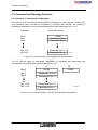
Command and Message Structure ............................................................... 5-4
Structure of Commands and Messages ....................................................... 5-4
5.3
5.3.1
5.3.1.1
5.3.1.2
5.3.1.3
5.3.2
5.3.2.1
5.3.2.2
5.3.3
5.3.3.1
5.3.3.2
Interface Description .................................................................................... 5-5
ISFP ............................................................................................................. 5-5
Program Structure ........................................................................................ 5-6
INTERBUS-S System Control ...................................................................... 5-8
Function Overview........................................................................................ 5-10
Bit-Controlled Command Execution.............................................................. 5-13
Description ................................................................................................... 5-13
Access to the Bit-Controlled Command Sequences ..................................... 5-13
IBS SYS SWT .............................................................................................. 5-16
Description ................................................................................................... 5-16
Commands................................................................................................... 5-18
5003B
iii
Contents
Startup ................................................................................................ 6-1
6.1
6.1.1
6.1.2
6.1.3
6.1.4
6.1.5
Introduction .................................................................................................. 6-1
General Information About Physical Addressing........................................... 6-1
General Information About Logical Addressing ............................................ 6-2
Modes of Operation...................................................................................... 6-2
Startup Behavior........................................................................................... 6-3
Acknowledgment Behavior ........................................................................... 6-4
6.2
Hardware Setting.......................................................................................... 6-5
6.3
Software Setting ........................................................................................... 6-6
7
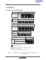
Installation .......................................................................................... 7-1
7.1
Slots for the Controller Board ....................................................................... 7-1
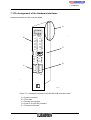
7.2
Cable Installation.......................................................................................... 7-2
7.3
7.3.1
7.3.2
7.3.3
7.3.4
Pin Assignment of the Hardware Interfaces.................................................. 7-3
System Connector........................................................................................ 7-4
Remote Bus Interface................................................................................... 7-5
Serial Interface (V.24/RS-232) ................................................................... 7-6
Ordering Information .................................................................................... 7-8
8
ISFP..................................................................................................... 8-1
8.1
8.1.1
8.1.2
8.1.2.1
8.1.2.2
8.1.2.3
8.1.2.4
8.1.3
8.1.3.1
8.1.3.2
Interface Description .................................................................................... 8-1
Program Structure ..................................................................................... 8-2
Inclusion of the Interface Drivers ............................................................... 8-5
INITIB (FB 60) .......................................................................................... 8-6
CON/IND .................................................................................................. 8-10
REQ/RES ................................................................................................. 8-12
INTERBUS Data Block (IBDB).................................................................. 8-14
INTERBUS-S System Control.................................................................... 8-16
Structure of the Functions......................................................................... 8-18
Overview of Functions .............................................................................. 8-20
on
l
in
ec
om
po
ne
nt
s.
co
m
6
8.2
8.2.1
8.2.1.1
8.2.1.2
8.2.1.3
8.2.1.4
8.2.1.5
8.2.1.6
8.2.1.7
8.2.1.8
8.2.1.9
8.2.1.10
iv
Command Functions .................................................................................... 8-24
CONTROL (FB 68) .................................................................................... 8-24
Configure INTERBUS-S (FKT 0)............................................................... 8-26
Start INTERBUS-S Cycle (FKT 1)............................................................. 8-26
Stop InterBus-S Cycle (FKT 2) ................................................................. 8-26
Alarm Stop (FKT 3)................................................................................... 8-26
Clear Display (FKT 4) ............................................................................... 8-26
Disable All Messages (FKT 5)................................................................... 8-27
Implement All Logical Address Map (FKT 6)............................................. 8-27
Init Communication (FKT 7) ...................................................................... 8-27
INTERBUS-S Delay (FKT 8) ..................................................................... 8-27
Quit Module Error All (FKT 9) ................................................................... 8-27
5003B
Contents
in
ec
om
po
ne
nt
s.
co
m
DEFINE (FB 69) ........................................................................................ 8-28
Physical Configuration Map (FKT 0) ......................................................... 8-30
Logical Local Bus Address Map (FKT 1)................................................... 8-31
Logical IN Address Map (FKT 2)............................................................... 8-32
Logical OUT Address Map (FKT 3)........................................................... 8-33
Communication Reference (FKT 4) .......................................................... 8-34
Event Map (FKT 5) ................................................................................... 8-35
Group Numbers (FKT 6) ........................................................................... 8-37
Parameter Timeout Constant (FKT 7) ....................................................... 8-38
Receive KBL (FKT 8)................................................................................ 8-39
Receive Bit Manipulation (FKT 9) ............................................................. 8-41
Group Error Characteristics (FKT 10) ....................................................... 8-50
Quit Module Error (FKT 11) ...................................................................... 8-52
SYSINFO (FB 70) ...................................................................................... 8-53
Physical Configuration Map (FKT 0) ......................................................... 8-55
Software Revision (FKT 1)........................................................................ 8-55
Switch Information (FKT 2) ....................................................................... 8-56
INTERBUS-S Cycle Counter (FKT 3)........................................................ 8-56
Logical Address Error (FKT 4) .................................................................. 8-57
ON/OFF (FB 71) ........................................................................................ 8-58
Group ON (FKT 0) .................................................................................... 8-60
Group OFF (FKT 1) .................................................................................. 8-60
BK-Alarm ON (FKT 2) ............................................................................... 8-60
BK-Alarm OFF (FKT 3) ............................................................................. 8-61
Event ON (FKT 4) ..................................................................................... 8-61
Event OFF (FKT 5) ................................................................................... 8-61
ADDRESS (FB 72) .................................................................................... 8-62
ID Code List.............................................................................................. 8-66
Bus Segment Address List........................................................................ 8-67
IN Address List ......................................................................................... 8-68
OUT Address List ..................................................................................... 8-69
Group No. List .......................................................................................... 8-70
Group Error Characteristics ...................................................................... 8-72
Communication Reference List ................................................................. 8-73
ERRINFO (FB 74)...................................................................................... 8-74
Controller Error Code (FKT 0)................................................................... 8-76
Bus Information (FKT 1) ........................................................................... 8-76
Defective Group (FKT 2)........................................................................... 8-77
Module Error (FKT 3)................................................................................ 8-78
Local Bus Module Error (FKT 4) ............................................................... 8-79
on
l
8.2.2
8.2.2.1
8.2.2.2
8.2.2.3
8.2.2.4
8.2.2.5
8.2.2.6
8.2.2.7
8.2.2.8
8.2.2.9
8.2.2.10
8.2.2.11
8.2.2.12
8.2.3
8.2.3.1
8.2.3.2
8.2.3.3
8.2.3.4
8.2.3.5
8.2.4
8.2.4.1
8.2.4.2
8.2.4.3
8.2.4.4
8.2.4.5
8.2.4.6
8.2.5
8.2.5.1
8.2.5.2
8.2.5.3
8.2.5.4
8.2.5.5
8.2.5.6
8.2.5.7
8.2.6
8.2.6.1
8.2.6.2
8.2.6.3
8.2.6.4
8.2.6.5
8.3
8.3.1
8.3.2
8.3.3
Message Functions ...................................................................................... 8-80
SYSERROR (FB 73).................................................................................. 8-80
RECONFIG (FB 75)................................................................................... 8-82
EVENT (FB 76).......................................................................................... 8-83
8.4
8.4.1
8.4.1.1
8.4.1.2
8.4.1.3
8.4.1.4
8.4.1.5
8.4.1.6
8.4.1.7
Working with Communication ....................................................................... 8-84
Introduction................................................................................................ 8-84
Control During Communication ................................................................. 8-86
Call Structure of the Function Blocks ........................................................ 8-86
Initialization/Addressing ............................................................................ 8-87
Service Structure ...................................................................................... 8-89
Service Execution ..................................................................................... 8-90
Activation Flag Service ............................................................................. 8-90
Message Flag Service .............................................................................. 8-92
5003B
v
Contents
in
ec
om
po
ne
nt
s.
co
m
Principal Service Sequence ...................................................................... 8-94
Example of a Service................................................................................ 8-96
Request/Confirmation ................................................................................ 8-97
Read Request........................................................................................... 8-100
Write Request ........................................................................................... 8-100
Start Request............................................................................................ 8-100
Stop Request............................................................................................ 8-100
Information Report Request...................................................................... 8-101
Status Request ......................................................................................... 8-101
Identify Request........................................................................................ 8-101
Initiate Request......................................................................................... 8-101
Abort Request........................................................................................... 8-102
Read Confirmation.................................................................................... 8-102
Write Confirmation .................................................................................... 8-102
Start Confirmation..................................................................................... 8-103
Stop Confirmation ..................................................................................... 8-103
Status Confirmation .................................................................................. 8-103
Identify Confirmation................................................................................. 8-104
Initiate Confirmation.................................................................................. 8-104
Initiate Error Confirmation ......................................................................... 8-104
Response/Indication .................................................................................. 8-106
Abort Indication......................................................................................... 8-106
Reject Indication ....................................................................................... 8-106
Start Indication.......................................................................................... 8-106
Stop Indication .......................................................................................... 8-106
Information Report Indication.................................................................... 8-107
Read Indication......................................................................................... 8-107
Write Indication ......................................................................................... 8-107
Initiate Indication....................................................................................... 8-108
Read Response ........................................................................................ 8-108
Write Response ........................................................................................ 8-108
Start Response ......................................................................................... 8-109
Stop Response ......................................................................................... 8-109
Application of Communication ................................................................... 8-110
Communication Error Messages................................................................ 8-113
Error Messages for a Connection Abort .................................................... 8-113
Error Messages for the Reject Service ..................................................... 8-115
Additional Error Messages........................................................................ 8-116
Description of the Service-Specific Error Messages ................................. 8-116
on
l
8.4.1.8
8.4.1.9
8.4.2
8.4.2.1
8.4.2.2
8.4.2.3
8.4.2.4
8.4.2.5
8.4.2.6
8.4.2.7
8.4.2.8
8.4.2.9
8.4.2.10
8.4.2.11
8.4.2.12
8.4.2.13
8.4.2.14
8.4.2.15
8.4.2.16
8.4.2.17
8.4.3
8.4.3.1
8.4.3.2
8.4.3.3
8.4.3.4
8.4.3.5
8.4.3.6
8.4.3.7
8.4.3.8
8.4.3.9
8.4.3.10
8.4.3.11
8.4.3.12
8.4.4
8.4.5
8.4.5.1
8.4.5.2
8.4.5.3
8.4.5.4
9
Commands and Messages ................................................................ 9-1
9.1
9.1.1
9.1.2
9.1.3
9.1.4
9.1.5
9.1.6
9.1.7
9.1.8
9.1.9
Controller Board Commands ....................................................................... 9-5
Commands for Bus Operation ................................................................... 9-6
Commands for Configuration ..................................................................... 9-9
Commands for Error Recovery .................................................................. 9-18
Commands for System Control.................................................................. 9-24
Commands for Addressing ........................................................................ 9-25
Commands for Process Data Linkage ....................................................... 9-27
Commands for Event Processing .............................................................. 9-34
Commands for Communication ................................................................. 9-38
Commands for the EEPROM Management ............................................... 9-38
vi
5003B
Contents
Controller Board Messages ......................................................................... 9-40
Messages of the User Interface ................................................................. 9-41
Messages for Bus Operation ..................................................................... 9-41
Messages for Configuration ....................................................................... 9-43
Messages for Error Recovery .................................................................... 9-49
Messages for System Control.................................................................... 9-60
Messages for Addressing .......................................................................... 9-61
Messages for Process Data Linkage ......................................................... 9-63
Messages for Event Processing ................................................................ 9-65
Messages for Communication ................................................................... 9-66
Messages for the EEPROM Management ................................................. 9-67
m
9.2
9.2.1
9.2.2
9.2.3
9.2.4
9.2.5
9.2.6
9.2.7
9.2.8
9.2.9
9.2.10
co
10 Appendix......................................................................................................... 10-1
s.
10.1 Overview of the DCB Revisions .............................................................................. 10-1
10.2 Technical Data........................................................................................................ 10-5
ne
nt
10.3 Contents of the Data Diskette ................................................................................. 10-6
po
Figures
Tables
on
l
in
ec
om
Index
5003B
vii
s.
nt
ne
po
om
in
ec
on
l
co
m
Contents
viii
5003B
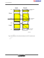
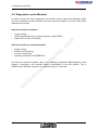
Chapter 1
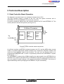
System Overview
This chapter provides information on
m
- the INTERBUS-S system and its components
- the basic INTERBUS-S system specifications
- the specific terms of the INTERBUS-S system
System Overview ............................................................................... 1-1
1.1
Networking with INTERBUS-S...................................................................... 1-1
1.2
1.2.1
1.2.2
1.2.3
1.2.4
1.2.5
INTERBUS-S Topology ................................................................................ 1-2
General Method of Operation ....................................................................... 1-3
Error Protection Mechanisms ....................................................................... 1-4
INTERBUS-S Protocol Sequence................................................................. 1-5
INTERBUS-S Scan Time Calculation ........................................................... 1-6
Basic System Specifications......................................................................... 1-10
1.3
1.3.1
1.3.2
1.3.3
1.3.4
1.3.5
1.3.6
1.3.6.1
1.3.6.2
System Components .................................................................................... 1-11
Host Controller Board ................................................................................... 1-11
Remote Bus ................................................................................................. 1-12
Installation Remote Bus................................................................................ 1-13
Bus Terminal Module.................................................................................... 1-15
Local Bus ..................................................................................................... 1-16
INTERBUS-S I/O Modules ........................................................................... 1-18
Remote Bus and Installation Remote Bus Modules...................................... 1-18
Local Bus Modules ....................................................................................... 1-18
5003B
on
l
in
ec
om
po
ne
nt
s.
co
1
5003B
s.
nt
ne
po
om
in
ec
on
l
co
m
1 System Overview
1 System Overview
INTERBUS-S, the high-speed and universal sensor/actuator bus system.
m
INTERBUS-S shifts the I/O level from a higher-level control system directly to the machine or
into the system. A serial bus cable connects the control system with the I/O modules in the
system. This reduces the cabling to a minimum as compared with conventional parallel
cabling.
s.
co
I/O signals
wired in parallel
in
ec
om
po
ne
I N T E R B U S - S
nt
I/O signals serially
transferred with
InterBus-S
5001A101
on
l
Figure 1-1: Optimization of the transfer structure with INTERBUS-S
1.1 Networking with INTERBUS-S
The constantly increasing degree of automation in general, but also the more complex
demands of production and process engineering require more and more powerful sensors
and actuators for the specific applications. Today, already more than 200 device
manufacturers support INTERBUS-S as an open bus system with the most various products.
This enables the users to always select the most powerful and low-cost components for their
specific application.
5003B
1-1
1 System Overview
Overview of INTERBUS-S-compatible devices
- Host controller boards/interface boards for
programmable logic controllers (PLC)
industrial computers and/or PCs
- I/O units for
digital inputs/outputs
analog inputs/outputs
degrees of protection - IP 20
- IP 65
s.
co
m
- High-tech control systems for
automatic wrenching
positioning
robots
ne
nt
- Drives
DRIVECOM standard
general motion control
po
- Pneumatic valve terminals
- Identification systems
in
ec
- Operator and display units
om
- Encoders
on
l
- Further devices with INTERBUS-S interface are in preparation.
1.2 INTERBUS-S Topology
INTERBUS-S is installed in the system as a compact single circuit line following one
direction. Starting at the host controller board, the bus system connects the respective
control or computer systems with the distributed I/O modules (INTERBUS-S modules).
The main line that is led through the plant is called remote bus and covers the distances
between the distributed substations.
Local branches (spur lines) are possible from the remote bus. Depending on the type, they
are either called installations remote bus or local bus.
1-2
5003B
1 System Overview
The installation remote bus corresponds - according to its structure - to the remote bus.
However, it provides the option to carry along a voltage supply for the sensors in the bus
cable (hybrid cable design).
At the beginning of the installation remote bus there is always a CBK module. The
installation remote bus may be set up with CDI, CDO, DIO and all remote bus modules.
The installation remote bus has been designed to install distributed sub-stations with a
direct connection of sensors and actuators. This results in an optimally short and low-cost
sensor/actuator connection.
m
The local bus has been designed for the cost-effective and flexible installation of
decentralized cabinets and terminal boxes. It interconnects the various local bus modules
and also establishes the connection to the bus terminal module (BK).
co
The bus terminal module (BK) connects the local bus to the remote bus.
s.
1.2.1 General Method of Operation
in
ec
om
po
ne
nt
The INTERBUS-S system is a data ring with a central master-slave access method. It has
the structure of a spatially distributed shift register. Every module forms with its registers a
part of this shift register, through which the master, i.e. the host controller board, clocks the
data serially.
With the ring structure it is possible to send and receive data synchronously (full duplex).
To simplify system installation, the ring system is implemented in one cable line.
Because of this, the system appears like a bus system with branching spur lines (simplified
tree structure).
Every station in the INTERBUS-S system has an ID register (IDentification register) which
includes information such as module type, number of I/O registers, as well as statuses and
error states. The I/O modules also have I/O registers for the process data transmission.
There are two types of cycles in an INTERBUS-S system:
on
l
- The ID cycle which is run upon request or to initialize the INTERBUS-S system. When the
host controller board is in the ID cycle it reads out the ID registers of all modules and uses
this information to generate the process image.
- The data cycle is the actual operating cycle which controls the data transfer. In the data
cycle, input data of all modules is read out of the registers and output data is shifted from the
host controller board to the modules.
Special test methods ensure a correct data transmission after every cycle.
- If no errors occurred during the data transmission the host controller board accepts the
data and/or outputs the data on the modules.
- If an error occurred, the data of the erroneous cycle is rejected because a new cycle is
completed faster than the correction of corrupted data.
5003B
1-3
1 System Overview
1.2.2 Error Protection Mechanisms
As a sensor/actuator bus the INTERBUS-S system has been designed for the use in
industrial environments.
In order to ensure a secure data transmission under the most various conditions of an
industrial field of application, the INTERBUS-S system features extensive protection
mechanisms.
The following precautionary measures ensure a safe data transmission:
co
m
Differential signal transfer in accordance with RS-485
The transfer in accordance with RS-485 uses a twisted-wire pair. User data is sent over both
lines of a pair as differential signals. This transfer method can be strongly affected by
influences from the outside and is used on the remote bus line and the installation remote
bus.
nt
s.
Remote bus check
The individual remote bus segments are checked by exchanging special status information.
An interrupt of the line or a connector which is not fitted properly causes a remote bus error
RB ERR and the ’RC’ LED on the remote bus module goes out.
om
po
ne
Loopback word
The controller board clocks this word ahead of the data through the ring (bus). Thus, the
loopback word is transferred directly between the input and output data through all
INTERBUS-S system modules and after the input data back to the controller board. The time
required for the loopback word to make a complete cycle is known to and monitored by the
controller board. The special bit sequence of the loopback word detects errors on the
transmission path or in the modules.
on
l
in
ec
CRC
Every transmission path between two modules in the INTERBUS-S system is checked by
means of a CRC (Cyclic Redundancy Check).
For this purpose, a CRC word is calculated both in the output direction as well as in the input
direction in every module and in the controller board itself. At the end of every transmission
cycle it is checked at the beginning and at the end of a transmission path if the values of the
check words match. If the values do not match, this will be reported to the controller board
through all following modules and a new cycle is started with current data.
A Hamming distance of 4 is reached with this check.
Test routines
In order to detect hardware faults on the INTERBUS-S host controller board, various test
routines are executed after a RESET or a voltage recovery.
These special routines check:
- the CPU of the INTERBUS-S protocol chip,
- the EPROM and RAM,
- the logic circuitries and functions of the various components.
1-4
5003B
1 System Overview
m
After error-free execution of the test routines, the green LED READY lights up.
Furthermore, the connected INTERBUS-S system is initialized and its functions are checked.
To this end, the controller board activates one bus segment after another and tests the
functioning of each.
First, the connection between the host controller board and the first bus terminal module or
the first remote bus module is enabled. When no errors occur, a local bus or installation
remote bus which is connected to the bus terminal is initialized. Afterwards, the connection
to the next remote bus station is enabled. In this way all segments of an INTERBUS-S
system are put into operation sequentially and bit by bit. After this configuration phase the
host controller board knows the connected INTERBUS-S system and can operate it.
This configuration algorithm is also used to locate the error if a malfunction occurs in the
course of normal data traffic.
co
1.2.3 INTERBUS-S Protocol Sequence
ne
nt
s.
- Starting with a loopback word, the controller board clocks the output data in the output
direction into the data ring of the INTERBUS-S system. At the same time the controller
board receives in the input direction the input data which has previously been stored in the
data ring by the INTERBUS-S modules.
po
- The loopback word is transferred between the output and input data through the entire data
ring, which is formed by all system modules. When the controller board receives the
loopback word, all output data is in the ring and all input data is in the controller board.
om
- The checksums calculated by the CRC generators are transferred to the next module
where they are checked.
on
l
in
ec
- When the loopback word is read back correctly and the comparison of the checksums
resulted in an error-free transfer on all bus lines, the output data becomes valid and the
modules put the data to their outputs. The controller board also passes the read input data
to the PLC for processing.
- Afterwards the controller board causes the modules to store all new input data in the ring,
before it clocks a new loopback word and new output data into the data ring.
- Due to the cyclic run of the INTERBUS-S protocol all I/O data is constantly updated.
5003B
1-5
1 System Overview
1.2.4 INTERBUS-S Scan Time Calculation
The scan time of the INTERBUS-S systems depends on few factors. It increases almost
linearly with an increasing number of I/O points.
Due to the high efficiency of the INTERBUS-S protocol, it is predominantly determined by the
number of I/O points. Furthermore, the number of bus terminal modules, the check
sequence, the signal propagation time, and the cable length of the bus system also influence
the scan time to a minor degree. The scan time can be calculated with the following simple
formula:
tcycle = ( 13 * ( 6 + n ) + 1.5 * m ) * tBit + tSW + tPH
s.
co
m
Transfer time in milliseconds
Number of user data bytes
Number of remote bus modules installed
Bit duration = 0.002 ms for 500 kbit/s
Software runtime = 0.2 ms
Runtime on the transmission medium
for copper: tPH=0.016 ms * l/km
l = length of the remote bus cable in kilometers
ne
nt
tcycle
n
m
tBit
tSW
tPH
po
When calculating the sum of I/O points, please observe that only the simple register length is
taken to calculate the total sum for modules that have inputs and outputs.
om
Example for determining the bit number which is used for the scan time calculation:
on
l
in
ec
Bus terminal module: IBS 24 BK I/O-T
16 bit inputs
16 bit outputs
Sum for n: 16
IBS 24 DI IBS 24 DO
16 bit inputs
--16 bit outputs
Sum for n: 32
1-6
5003B
1 System Overview
X3
A01
ID:65
24 DO PT 100
ID:129 ID:70
IBS IP CBK
ID:12
om
po
ne
nt
s.
co
BK-T 24 DI
ID:52 ID:130
m
X2
IBS IP CDI
ID:9
IBS IP CDI
ID:10
on
l
in
ec
ID:10
IBS IP CDO
BK I/O-T
24 DI/32
ID:11
ID:142
AI 3
ID:71
5001A109
5001A108
Figure 1-2: Example for a scan time calculation
5003B
1-7
1 System Overview
Example for a scan time calculation on a demo bus:
The columns in the table show the inputs, outputs, and the number of bits on every module
which are used to calculate the scan time.
co
m
Register width
2
8
2
8
2
2
2
2
2
4
8
n=42
nt
ne
Number of user data bytes = 42
Outputs*
8
2
-1
--1
-2
-8
22
po
Inputs*
2
8
2
1
1
2
4
8
28
* The numbers are given in bytes.
s.
Module
IBS 24 BK-T
IBS 24 DI
IBS 24 AO1
IBS 24 DO
IBS PT 100
IBS 24 IP DIO
IBS IP CBK
IBS 24 CDI
IBS 24 CDO
IBS 24 CDI
IBS 24 BK I/O-T
IBS 24 DI/32
IBS 24 AI 3
om
Number of the remote bus modules installed = 7
Cable length (copper) e.g. = 400 m
in
ec
tcycle = (13 * (6 + n) + 1.5 * m) * tBit + tsw + tPH
on
l
tcycle = (13 * (6 + 42) + 1.5 * 7) * 0.002 ms + 0.2 ms + 0.016 ms/km * 0.4 km = 1.475 ms
1-8
5003B
1 System Overview
PLC
Host controller
board
co
m
Local bus
om
Installation remote bus
in
ec
Remote bus
po
ne
nt
s.
Bus terminal
IP 20
on
l
Bus terminal
IP 65
Local bus
Bus terminal
IP 20
5001A108
5001A108
Figure 1-3: INTERBUS-S topology with the various bus types
5003B
1-9
1 System Overview
1.2.5 Basic System Specifications
Remote bus
Max. bus cable length between:
host controller board and first remote bus module
400 m
two remote bus module
400 m
host controller board and last remote bus module
13 km
Installation remote bus
Max. total current consumption:
m
4.5 A
co
Max. bus cable length between:
s.
BK and first I/O module
nt
two I/O modules
50 m
50 m
po
ne
BK and last I/O module
50 m
in
ec
om
The number of the I/O modules in the installation remote bus is limited by the
current consumption of the modules and the connected initiators.
The overall current consumption of these components must not exceed
4.5 A. The current consumption of the actuators is not added to the calculation,
because actuators are always supplied with a separate voltage.
on
l
Local bus
Max. number of modules in the local bus:
Max. 8, (depending on the current
consumption of every module and
the load carrying capacity of the
bus terminal module, see data
sheets for more information )
Max. bus cable length between:
1-10
BK and first I/O module
1.5 m
BK and last I/O module
10 m
5003B
1 System Overview
1.3 System Components
1.3.1 Host Controller Board
s.
co
m
The INTERBUS-S system is a sensor/actuator bus that is independent of the control system.
The link to the respective control system is achieved with a special host controller board for
every control system.
The host controller board is inserted into the mounting rack of the control system. The
controller boards for the programmable logic controllers (PLCs) always couple passively to
the I/O bus of the respective control system, like system-contained I/O units. In the control
system, the host controller board operates like a system-contained I/O board, so that all
control functions and programming commands can be handled in the usual way. In addition,
it ensures the cyclic data traffic (with the exception of the PC interface boards) and the error
display in the INTERBUS-S system.
There are two types of controller boards which are called DCB (= Diagnostic Controller
Board) and DAB (= Diagnose Anschaltbaugruppe).
on
l
in
ec
om
po
ne
nt
Host controller board functions:
- Control of the cyclic INTERBUS-S protocol (with the exception of the PC interface
boards)
- Transfer of output and/or input data to the IBS-S modules and/or the control system
- Monitoring of the INTERBUS-S system
- Fault detection
- Determining the type and location of the fault
- Reporting errors to the control system
- Optical diagnostic functions
- Operating indicators
- Error indicators
- I/O status
MODE
ADDRESS
BYTE
n+1
0/0
n
8/0
9/1
10/2
11/3
12/4
13/5
14/6
15/7
READY
BASP
RUN
BSA
X2
1/1
2/2
3/3
4/4
5/5
6/6
7/7
CTRL
RB
LB
MOD
X3
REMOTE
RS 232
RESET
5001B103
IBS A25
DCB/I-T
IBS S5
DCB/I-T
IBS PC CB/I-T
IBS PC CB/COP/I-T
Figure 1-4: Host controller boards for the various computer and control systems
5003B
1-11
1 System Overview
1.3.2 Remote Bus
The remote bus covers the long distances within a system. The entire remote bus may be up
to 12.8 km long (from the host controller board to the last remote bus module connected).
This is achieved by dividing the entire remote bus into individual segments.
A remote bus segment consists of the transmission line (remote bus cable) and the bus
terminal module connected to it. I/O modules may be connected to the bus terminal module.
A remote bus segment can bridge up to 400 m.
In this way the entire remote bus can be divided into a maximum of up to 256 remote bus
segments (when a DCB controller board is connected) (see Figure 1-5).
co
m
The installation remote bus, which will be described in the next chapter, also
consists of remote bus segments. They have to be considered in an
appropriate way when the sum of the remote bus segments is determined.
nt
s.
Remote bus and installation remote bus are abbreviated "RB".
Please take this into account for the error messages of the host controller
board (Chapter 5).
ne
InterBus-S
host controller
board
om
po
PLC
in
ec
Remote bus
segment
max. 400 m
on
l
Remote bus
max. 12.8 km
Remote bus
segment
max. 400 m
5001A102
Figure 1-5: Structure and maximum dimensions of the remote bus
1-12
5003B
1 System Overview
Remote bus
Max. number of remote bus segments
for controller boards:
(incl. installation remote bus)
(DCB)
(DAB)
(PC CB/COP/I-T)
(PC CB/I-T)
(PC AT-T)
Max. length of a remote bus segment:
256
64
256
256
32
400 m
co
m
400 m
400 m
12.8 km
RS-485
simple, shielded signal line
s.
Max. bus cable length between:
host controller board and first remote bus module
two remote bus modules
host controller board and last remote bus module
Transmission method:
Transmission medium:
nt
Alternatively, the following media may be used for the remote bus:
om
po
ne
- Fiber optic cable
- Slotted waveguide
- Infrared transmission
- Slip ring
in
ec
1.3.3 Installation Remote Bus
on
l
The installation remote bus is a spur line which branches off from the remote bus. From the
physical point of view it is a remote bus.
A corresponding bus terminal module (e. g. IBS IP CBK) couples the installation remote bus
to the main remote bus cable.
Apart from the actual 24 V DC data lines, the voltage supply lines for the module electronics
and the initiators are also carried in the special installation remote bus cable (hybrid cable).
5003B
1-13
1 System Overview
Installation remote bus
Incoming
remote bus
max. 50 meters
IBS IP CDO
IBS IP CDI
IBS IP CDO
m
IBS IP CBK
Outgoing
remote bus
co
5001A105
s.
Figure 1-6: Structure and maximum dimensions of the installation remote bus
po
ne
nt
Remote bus and installation remote bus are often referred to by their
abbreviation "RB".
Please take this into account for the error messages of the host controller
boards (Chapter 5).
in
ec
om
The installation remote bus interface is designed especially to connect the INTERBUS-S I/O
modules IBS IP CDI and IBS IP CDO with the IP 65 degree of protection.
It is possible to integrate all remote bus modules with a two-wire interface into the installation
remote bus. It is not possible to set up another spur with a bus terminal module.
Basic installation remote bus specifications
Max. bus cable length between:
on
l
CBK bus terminal and first I/O module
CBK bus terminal and last I/O module
Max. current carrying capacity of the hybrid cable:
50 m
50 m
4.5 A
The number of I/O modules in the installation remote bus is limited by the current
consumption of the modules and the connected initiators.
The overall current consumption of these components must not exceed 4.5 A.
The current consumption of the actuators is not added to the calculation because
the actuators are supplied with a separate voltage.
1-14
5003B
1 System Overview
Calculation example for determining the number of modules in the installation remote
bus:
Let us assume that the following components are used in an installation remote bus. (The
information on the current consumption of the I/O modules and initiators is taken from the
appropriate data sheets).
Table 1-1: Example for testing the load capacity of an installation remote bus
ne
nt
s.
co
m
Current consumption by the module electronics of 100 mA
a CDO or CDI module:
Current consumption of a typical initiator:
25 mA
Number of CDO modules:
4
Number of CDI modules:
8
Number of the connected initiators:
27
Total current consumption:
4* 100mA + 8*100 mA + 27*25 mA
= 1.875 A
Bus operation is ensured in this example!
1.3.4 Bus Terminal Module
on
l
in
ec
om
po
A bus terminal module belongs to the remote bus. It connects a local bus (cf. Chapter 1.3.5)
and/or installation remote bus to the remote bus (cf. Chapter 1.3.2). The supply voltage of a
bus terminal module must be maintained even when parts of the system are disconnected.
Only then can it be guaranteed that the remaining part of the bus system can continue
operation.
Bus terminal modules may be identified by the designation BK (IBS IP CBK 1/24-F, IBS 24
BK I/O-T, IBS BK-T, IBS 24 BK/LC 2, IBS 24 BK-I/O, IBS 230 BK, IBS 24 BK, IBS 24
BK/LC). There are also bus terminal modules with additional I/O functions (I/O is included in
the name).
If the supply voltage at a bus terminal module fails, the controller board stops the
system and generates an error message for the remote bus segment concerned.
Bus terminal functions:
- Coupling an installation remote bus and/or local bus to the remote bus
- Supplying the I/O modules with the operating voltage for the bus electronics
- Regenerating data in the remote bus
- Electrical isolation between remote bus segments
- Switching on or off the local bus, installation remote bus, and the outgoing remote bus
- Indicating errors via a floating alarm output
- For the IBS 24 BK/LC 2: reconfiguration by means of an external pushbutton
5003B
1-15
1 System Overview
Incoming remote bus
ne
nt
s.
co
m
Local bus (or installation remote bus)
Bus terminal module
po
Outgoing remote bus
5001A106
in
ec
om
Figure 1-7: Remote bus at the interface to the local bus
1.3.5 Local Bus
on
l
The local bus is a local branch of the main remote bus line which is used inside of a switch
cabinet. It allows the variable and low-cost installation of a distributed substation.
The local bus is coupled via a bus terminal module to the main remote bus line. In the local
bus itself different I/O modules can be combined with one another.
Local bus modules cannot be integrated into the remote bus or installation remote bus.
Conversely, it is not possible to use remote bus modules in the local bus.
The local bus is also referred to by its abbreviation "LB". Please take this into
account for the error diagnostics of the host controller board (Chapter 5).
1-16
5003B
1 System Overview
Incoming remote bus
Local bus
max. 10 m
max.
1.5 m
max.
1.5 m
po
ne
nt
s.
co
m
max.
1.5 m
om
Bus terminal module
5001A107
in
ec
Outgoing remote bus
Figure 1-8: Local bus structure and maximum dimensions
on
l
Basic local bus specifications
Max. total current consumption:
0.8 A
Max. bus cable length between:
BK and the first local bus module
1.5 m
two I/O modules
1.5 m
BK and last local bus module
10 m
Max. number of I/O modules in the local bus:
8
You may use preassembled connecting cables with lengths of 10 cm
(27 84 17 5), 20 cm (27 06 31 2), 50 cm (27 59 43 0), 100 cm (27 84 18 8) and
150 cm (27 84 19 1) from Phoenix Contact. (The order numbers are given in
parentheses.)
5003B
1-17
1 System Overview
1.3.6 INTERBUS-S I/O Modules
The I/O modules link the sensors and actuators to the INTERBUS-S system. Here, a
distinction is to be made between I/O modules in the remote bus and/or installation remote
bus and the I/O modules in the local bus.
1.3.6.1 Remote Bus and Installation Remote Bus Modules
m
Besides I/O modules for digital and analog signals there are I/O modules with
bus terminal functionality, such as IBS 24 BK I/O-T, and operator terminals,
valve terminals, DRIVECOM devices, ENCOM devices, etc.
s.
co
If the supply voltage U (CDO, CDI UL) fails in a remote bus or installation
remote bus module, the INTERBUS-S system is stopped and an error
message for the respective remote bus segment is output.
in
ec
om
po
ne
nt
For the INTERBUS-S system operation it is necessary that the bus logic of all
modules is supplied with voltage.
The voltage (U) for supplying the bus logic is for
- remote and local bus modules directly connected to every I/O module and
every BK.
- installation remote bus modules provided via the special installation remote
bus cable.
The voltage is supplied through the BK, which is coupled to the main line in
the respective installation remote bus.
on
l
1.3.6.2 Local Bus Modules
Local bus modules are I/O modules for the variable and cost-effective installation in a
decentralized switch cabinet.
In a local bus the modules can be combined with regard to their respective control and
monitoring tasks.
The local bus modules of a local bus are coupled through a bus terminal module to the main
remote bus line. The bus terminal module features an integrated power pack. It supplies the
BK electronics and, via the local bus cable, the bus logic of the connected I/O modules.
The voltage supplied at the respective I/O module serves to supply the peripheral side which
is electrically isolated from the bus logic.
If the voltage fails in the bus terminal module, the INTERBUS-S system stops and the
controller board reports an error for the remote bus segment concerned.
When calculating the sum of the I/O points, please observe that for modules with inputs and
outputs only the simple register width is taken for calculating the total sum.
1-18
5003B
Chapter 2
Technical Description
This chapter provides information on
m
- the functions of the operating and display elements of the controller board
- the project planning of the controller board
- the hardware settings in order to get different modes of operation
- the technical data
Technical Description........................................................................ 2-1
2.1
Host Controller Board Method of Operation.................................................. 2-1
2.2
Application Area of the Host Controller Board .............................................. 2-2
2.3
2.3.1
2.3.1.1
2.3.1.2
2.3.1.3
2.3.1.4
2.3.2
Overview ...................................................................................................... 2-3
Front Plate Components............................................................................... 2-4
I/O Status Indicators..................................................................................... 2-5
Operating Indicators ..................................................................................... 2-6
Error Indicators............................................................................................. 2-7
Interfaces ..................................................................................................... 2-7
Controller Board Components ...................................................................... 2-8
2.4
2.4.1
Host Controller Board Installation ................................................................. 2-9
Slot Allocation and Installation...................................................................... 2-9
2.5
2.5.1
2.5.2
2.5.3
Configuration of the Controller Board ........................................................... 2-11
PLC Address Area........................................................................................ 2-11
Hardware Term Definitions .......................................................................... 2-12
Configuring the Default Setting..................................................................... 2-13
2.6
2.6.1
2.6.2
2.6.3
2.6.3.1
2.6.3.2
2.6.3.3
2.6.3.4
2.6.3.5
2.6.4
2.6.5
2.6.5.1
2.6.5.2
2.6.6
2.6.7
Hardware Settings........................................................................................ 2-19
Mounting Positions of the Jumpers............................................................... 2-19
Operation in the Central Controller and Controller Expansion Unit ............... 2-20
Startup and Operating Mode Selection......................................................... 2-21
INTERBUS-S in the PLC’s Address Area ..................................................... 2-25
Address Locations for Automatic Start in the DCB Mode.............................. 2-26
Address Locations for Controlled Start in the DCB Mode ............................. 2-27
Address Locations for Automatic Start in the DAB Mode.............................. 2-28
Address Locations for Controlled Start in the DAB Mode ............................. 2-29
Address Windows......................................................................................... 2-30
Interrupt Processing ..................................................................................... 2-36
Settings for Interrupt Processing .................................................................. 2-36
Different Interrupt Sources ........................................................................... 2-38
Acknowledgment Delay Message ................................................................ 2-38
Disconnecting the RESET Button................................................................. 2-39
2.7
5003B
on
l
in
ec
om
po
ne
nt
s.
co
2
Data Sheet ................................................................................................... 2-40
5003B
s.
nt
ne
po
om
in
ec
on
l
co
m
2 Technical Description
2 Technical Description
2.1 Host Controller Board Operation
Host
Interface
co
To the
PLC
ne
nt
IPMS
To
Multi
Port
Memory
s.
M 68xxx Processor
m
The diagnostic controller board is an intelligent I/O board for the PLC.
The host controller board is coupled to the PLC with the system connector and to
INTERBUS-S with the INTERBUS-S remote bus connector.
A memory component (MPM) forms the interface between the PLC and INTERBUS-S. This
memory allows to access the systems (see Figure 2-1).
5003A201
om
po
INTER BUS-S
in
ec
Figure 2-1: Host controller board components
on
l
An efficient interface circuit (host interface) between the PLC and the MPM allows several
modes of operation and a fast transfer between the components. Registers indicate and
control the host controller board’s user functions. The user can use function blocks or a
programmable EEPROM card in order to dynamically influence the INTERBUS-S system
performance.
The INTERBUS-S protocol chip (IPMS) simplifies the data transfer from INTERBUS-S to
the MPM. The computer (M 68xxx-CPU) is offloaded so that data can be preprocessed. The
user can respond to signal changes of the outputs and address INTERBUS-S by means of
logical addressing without prolonging the INTERBUS-S cycle considerably.
5003B
2-1
2 Technical Description
2.2 Application Area of the Host Controller Board
The INTERBUS S5 host controller board ensures asynchronous communication between the
programmable controllers and the INTERBUS-S I/O system.
The host controller board includes operating and diagnostic indicators, which provide
information about the board’s status and the connected INTERBUS-S system.
A software package and a memory block constitute the interface between the control
program and the controller board. Diagnostic, command and special user functions can be
called through this interface.
S5 135 U
S5 150 U
S5 130 WB
S5 155 U
co
S5 115 U
S5 150 S
m
The host controller board may be used in the following SIMATIC S5 PLCs:
s.
Other Siemens or compatible PLCs upon request.
po
256 local bus segments and/or remote bus modules
320 modules
256 INTERBUS-S words
62 PCP stations.
om
max.
max.
max.
max.
on
l
in
ec
•
•
•
•
ne
nt
When coupled to the S5 backplane bus, the controller board can be used with all Siemens
modules.
The two-wire INTERBUS-S system is connected through the remote bus connector. A bus
system with the following expansion can be set up:
2-2
5003B
2 Technical Description
2.3 Overview
This section briefly describes the most important components of the host controller board.
The board’s front plate is explained first, followed by an explanation of its visible components
(printed board with system connector).
The designations used below are retained throughout the user manual.
(3)
s.
co
m
(2)
(1)
nt
5003A202
ne
Figure 2-2: Front plate (1), board (2) and system connector (3) of the controller board
om
po
(1) Front plate:
The front plate is externally accessible and contains all operating and display elements of the
controller board.
on
l
in
ec
(2) Printed circuit board with system connector (3):
The PCB with the system connector is the part of the host controller board that is inserted
into the PLC. The front plate is the termination to the front.
5003B
2-3
2 Technical Description
2.3.1 Front Plate Components
CTRL
BASP
RB
RUN
LB
MOD
X3
REMOTE RS 232
RESET
on
l
in
ec
om
X2
po
BSA
ne
READY
nt
s.
co
m
MODE ADDRESS
BYTE
n
n+1
0/0
8/0
9/1
1/1
10/2
2/2
11/3
3/3
12/4
4/4
5/5
13/5
6/6
14/6
7/7
15/7
5003A203
Figure 2-3: Front plate of the DCB controller board
2-4
5003B
2 Technical Description
2.3.1.1 I/O Status Indicators
The I/O data of the INTERBUS-S modules can be indicated on the front plate. The module
address is entered by means of coding switches.
4-8
Must not be set
co
Address area
Inputs, P area
Outputs, P area
Inputs, Q area
Outputs, Q area
ne
nt
s.
MODE
0
1
2
3
m
MODE
Selection of the address area:
om
po
ADDRESS
The required byte address is set by means of three coding switches. Only a word address
(even address) is accepted as a valid address. The address which is set must be used by an
INTERBUS-S module.
"Ad" is displayed on the front plate whenever a set address is invalid.
on
l
in
ec
I/O DATA (yellow LEDs)
The data item of the set address is output as a 16-bit word. The word is shown with the
bytes n (set even address) and n+1.
Displays on the seven-segment display with coding switch position 918x
With the coding switch position 918x the seven-segment display shows the numbers of the
ten modules with the most transmission errors. The position 9180 shows the module that
has most errors, the position 9181h the module with the second most errors, etc.
If there are less than 10 modules with errors, the seven-segment display shows less than 10
module numbers. "Ad" is displayed on the free locations. Transmission errors which occur
between the last module and the controller board are displayed with the module number FF.
In addition, all I/O data LEDs light up.
The hundred position of the module numbers is also indicated with the I/O data LEDs. The
LED 0 lights up for the module numbers 0 through 99, the LED 1 for the module numbers
100 trough 199, the LED 2 for the module numbers 200 through 299, and so on. LED 5
lights up for the module numbers 500-511.
5003B
2-5
2 Technical Description
Displays on the seven-segment display with the coding switch position 919x
When the coding switches are in position 9190, the seven-segment display shows the
number of the local bus station in which the last module status error occurred. The position
9191 indicates the number of the local bus station of the last but one module status error
and so on.
m
Displays on the seven-segment display with the coding switch position 94xx to 99xx
When the coding switches are in position 9400, the seven-segment display shows the
number of modules in the current configuration.
When the coding switches are in position 9401 through 9912, the seven-segment display
shows the ID codes (hexadecimal) of the current physical configuration ("9401" shows the ID
codes of the first bus station, "9402" shows the ID codes of the second bus station, etc.).
The register length of the modules is given in the first digit of the three-digit display.
nt
s.
co
Display of the firmware revision
The coding switch position 9200 shows the implemented firmware revision on the sevensegment display.
po
ne
DIAGNOSTICS (seven-segment display)
The three-position seven-segment display shows parameters during operation an when
errors occur.
in
ec
om
-- Controller board stop
-Run status of the controller board
Ad Invalid address set with the coding switch
A parameter is output in case of an error (an error LED is active).
2.3.1.2 Operating Indicators
on
l
Various LEDs indicate the operating state of INTERBUS-S and the PLC. The sevensegment display provides more detailed information.
READY
The controller board has completed the self-test without discovering any errors and is ready
for operation.
BASP
The PLC has activated the BASP (Befehls Ausgabe SPerren = disable command output)
signal and is in the STOP state. In this operating state, INTERBUS-S resets all outputs.
RUN
The RUN LED is active when a data cycle runs on INTERBUS-S.
BSA
The BSA signal (Bus Segment Abgeschaltet = bus segment disabled) indicates that one or
several bus segments is/are disabled. The remaining bus configuration runs properly.
2-6
5003B
2 Technical Description
2.3.1.3 Error Indicators
INTERBUS-S malfunctions are indicated by various LEDs. More detailed information is
provided by the seven-segment display.
CTRL
The CTRL ERR (ConTRoLler Error) reports an error restricted to the controller board or its
parameterization. A description of the error numbers (hex) is given in Chapter 4, "Diagnostic
Interfaces".
m
RB
A defective remote bus (Remote Bus Error) has been diagnosed. The seven-segment
display shows the number (in decimal) of the defective remote bus segments.
s.
co
LB
A defective local bus (Local Bus Error) has been diagnosed. The seven-segment display
shows the number (in decimal) of the defective local bus segment.
po
ne
nt
MOD
A MOD ERR (MODule Error) occurs when an INTERBUS-S module indicates an error (e. g.
short circuit in the periphery or lacking voltage supply) (only possible in the case of modules
with bus acknowledgment). The seven-segment display shows the number (in decimal) of
the local bus in which the reporting module is located. The other parts of the bus run
properly.
in
ec
om
RESET
When this pushbutton is actuated (using a tool), the host controller board and the connected
INTERBUS-S are reset.
on
l
A RESET must only be triggered when the PLC is in the STOP state. As long as
the controller board runs through a self-test, no current inputs are read and no
current outputs are set. When the controlled start is used, the bus cycle is not
re-started (no RUN). All parameter settings are canceled (log. addressing, event
definitions, ...).
2.3.1.4 Interfaces
REMOTE
The INTERBUS-S remote bus interface links the host controller board with the INTERBUSS I/O modules. The interface port is a 9-pos. D-SUB female connector which is located on
the front plate of the host controller board. The connection to INTERBUS-S is designed as a
two-wire remote bus.
RS-232
The host controller board has a serial interface implemented. The interface port is a 9-pos.
D-SUB male connector which is located on the front plate of the host controller board.
5003B
2-7
2 Technical Description
on
l
in
ec
om
po
ne
nt
s.
co
m
The connector pinouts can be found in the section where the interface is described.
2-8
5003B
2 Technical Description
2.3.2 Controller Board Components
9
4
2
1
7
3
m
10
s.
co
5
po
7
ne
nt
6
8
5003A204
om
Figure 2-4: DCB with system connector
(2) EEPROM slot
Slot for the EEPROM memory card.
(3) Mounting location 1
INTERBUS-S master board
(4) System connector
The system connector is the link between host
controller board and PLC.
on
l
in
ec
(1) Front part
The front part comprises the interface
ports and the diagnostic indicators.
(5) Mounting location 2
Reserved location
(6) Jumper IBS S5 DCB/I-T
Settings:
•
Mode of operation • Interrupt selection
•
Master/slave
(7) DC/DC converter
Two DC/DC converters for electrical
isolation of the board’s voltage supply
(one converter is fitted).
(8) DIL switch for addressing
The addresses of the controller board are set
by means of DIL switches. No address settings
are required for the controlled DCB mode (see
2.5.3, 2.3.6)
(9) Version number
Version and controller board designation
are noted on the back of the board.
(10) Decoder EEPROM
The decoder EEPROM stores the configured
addresses.
5003B
2-9
2 Technical Description
2.4 Host Controller Board Installation
2.4.1 Slot Allocation and Installation
m
The DCB consists of a printed board in the double Euroformat. The front plate covers two
slots for printed circuit boards. In SIMATIC PLCs of the type 130 U (and larger), the
controller board can be directly inserted. In SIMATIC 115 U PLCs, an adaptation casing
must be used.
A standard EEPROM memory card stores the non-volatile configuration data (e.g. logical
addressing). On the host controller board the memory card is located below the mounting
location 1 (see Figure 2-4 (3)). The memory card sits in a holding support with an ejection
mechanism and can only be replaced when the board is not plugged in.
co
Live insertion or removal of the controller board causes damage.
on
l
in
ec
om
po
ne
nt
s.
Slots:
Installation options of the DCB in SIMATIC PLCs of types S5-155U, -150 U, -135 U,
-130 WB and -115 U.
2-10
5003B
2 Technical Description
3
11
19
27
35
43
Sl ot desi gnati on
51
59
67
75
83
91
99
107
115
123
131
139
147
155
163
Table 2-1: Permissible slots for the S5-155U, -130 WB, - 135 U, - 150 U, -155 U SIMATIC
PLCs
S 5-1 5 0U
Mode
S5-155U
89
99
107
83
99
163
155
m
147
139
131
co
123
115
107
s.
137
145
153
163
IM
6
5
4
3
2
1
0
CPU
Sl ot designati on
PS
in
ec
om
3
27
35
43
Sl ot desi gnati on
51
69
79
89
97
105
113
121
129
po
ne
IS F P
S o f tw a r e
S5-130WB
91
nt
I n te rr u p t
p ro c e s s in g
S5-135U
163
79
75
19
Software
us ed
Slot
designation
155
69
67
S5-150U
147
59
131
139
51
59
123
43
51
115
35
27
27
43
11
19
35
3
11
Slot desi gnation
3
S 5-1 55 U
M ode
CR 700-0 LA12 rack
on
l
S5-115U
C R 70 0-0 LB 1 1 rack
C R 7 0 0 - 1 L A 1 2 ra c k
CR 700-2 LA 12 rack
CR 700-3 LA12 rack
Installation possible
Installation possible if bridge BR7, at the back of
the rack, is installed.
(see Siemens S5 155 U user manual)
5003A236
Other PLC types upon request.
5003B
2-11
2 Technical Description
2.5 Configuration of the Controller Board
2.5.1 PLC Address Area
m
The S5 PLC has an I/O address area of 256 bytes. The address area is provided in duplicate
to produce one input and one output address area. The I/O modules are located in this
address area (P area).
With every PLC cycle, the first 128 bytes (byte 0 to byte 127, depending on the PLC) are
mapped onto a further memory area. This area (process image of the inputs and outputs) is
preferably used for digital I/O modules. Bit combinations can be done with these addresses.
Addresses outside the process image, however, must be loaded or transferred directly (L
PW, T PW).
co
Extended address area
ne
nt
s.
In some PLCs, an additional address area (Q area) is provided which enlarges the I/O area
by 256 bytes. The P and Q areas are addressed by means of different load and transfer
commands. (L PW x or L QW x)
om
PLC
po
If the PLC accommodates SIMATIC I/O modules in its central controller, the
addresses which these modules use are stored in the P and Q areas,
respectively (see user manuals for SIMATIC PLCs).
255
on
l
Q area
in
ec
255
Output area of
the PLC
Input area of the
PLC
0
255
0
255
128
P area
Process image
127 PIO (Outputs)
127 PII (Inputs)
128
127
127
0
0
0
5003A322
Figure 2-5: I/O area of the PLC
2-12
5003B
2 Technical Description
The input byte 0 in the PLC’s I/O area has a special function. This byte transfers the interrupt
number of the requesting controller board to the PLC. Thus, for controller boards with
interrupt capability the input word 0 (byte 0 and byte 1) is no longer available as an input
address.
If the controller board’s interrupt line is activated, the board is capable of
interrupts and, therefore, occupies the periphery input word 0.
2.5.2 Hardware Term Definitions
s.
co
m
I/O area of the PLC with IBS S5 DCB I/T
Byte 255
Q area
Module address
ne
nt
Communication register
DAB
om
Byte 000
po
Window area 2
Module address
Byte 255
DAB
DCB
in
ec
Window area 1
P area
on
l
Application register
Diagnostic register
Byte 000
5003B217
Figure 2-6: Variable locations for registers and window areas
Inputs/outputs
The peripheral area of the PLC with the P and Q areas and the process image is called the
input/output (I/O) area of the PLC.
5003B
2-13
2 Technical Description
Window areas
Window areas are address areas in the PLC which are occupied through the host controller
board. They are set with DIP switches on the host controller board and can occupy inputs or
outputs, depending on the board’s mode of operation.
Module addresses
Module addresses are the I/O addresses in the PLC which are used by an input or output
module. The application program accesses these addresses in order to link inputs and to set
outputs. Depending on the mode of operation, these addresses can be within or outside the
window areas.
s.
co
m
Diagnostic registers
The host controller board automatically monitors the entire bus system and diagnoses errors
if they occur. The diagnostic result is displayed on the front plate. This data can also be
called by the application program via the diagnostic registers (diagnostic bit register,
diagnostic parameter register).
ne
nt
Application registers
Different I/O words are used to perform functions on the controller board and the bus system
(bit-controlled command register, bit manipulation register).
in
ec
om
po
Communication registers
These registers are always active in the PLC. They are addressed by means of the included
function (driver) blocks (FBs). Using these blocks, control commands and/or messages can
be exchanged between the PLC and the controller board.
2.5.3 Configuring the Default Setting
on
l
In order to configure the available addresses, jumpers and DIP switches on the controller
board, the following information will be of importance:
Definition of I/O addresses
Depending on the number of inputs or outputs, every module occupies 8, 16, 32 or more bits
in the PLC. In the PLC, every module is accessible through the controller board. The host
controller board displays every input and output data item word by word (as the smallest
unit). Here, the base address of the module is decisive. The host controller board allows two
different types of addressing. The address area which the host controller board occupies is
variable.
2-14
5003B
2 Technical Description
Configuration of the controller board
Logical
addressing
Automatic
start
Controlled
start
nt
s.
co
m
Physical
addressing
DCB mode
ne
DAB mode
5003A233
om
po
Address behavior to the PLC
Figure 2-7: How to proceed to determine the mode of operation
on
l
in
ec
Physical addressing
• The modules are addresses in their physical order.
• Only modules which the host controller board has recognized in the INTERBUS-S
system will be addressed.
• The address location is predetermined by the hardware setting of the board.
If you remove one or several modules from the configuration when the bus
stands still, the host controller board cannot recognize this modification when
the physical addressing is used. Depending on your application this case may
lead to dangerous situations during the process run.
Logical addressing
• The user allocates an address to every module.
• The host controller board checks whether or not the expected modules are connected to
the INTERBUS-S system in the specified way.
• The address location can be specified independently of the hardware setting of the
board.
5003B
2-15
2 Technical Description
on
l
in
ec
om
po
ne
nt
s.
co
m
Please note that the addressing modes are described in the Chapter "User
Interfaces".
Chapter 2.6.3 "Startup and Operating Mode Selection" describes the different
DAB/DCB modes.
2-16
5003B
2 Technical Description
Hardware settings
The different operating and addressing modes, the connected PLC, and the signaling
behavior of the controller board require several presettings. The following sequence diagram
gives in the left column the description of the setting and in the right column the respective
switch. A detailed description of the jumpers and DIP switches is given in the Chapter 2.6,
"Hardware Settings".
Description
Setting
Setting: Communication registers
Mode:
DAB
DCB
DAB
1
YES
YES
YES
YES
YES
YES
YES
YES
2
Base:
Length:
om
YES = to be set
YES
YES
Switch 6
DCB
YES
YES
Switch 6
NO
NO
Switch 1
Switch 2
NO
NO
Switch 3
ne
Base:
Length:
Window:
Controlled
po
Window:
co
Automatic
s.
Operation:
Jumper 1
Switch 4
NO = not relevant
Jumper 3
Error message but PLC stop with acknowledgment delay
Jumper 4
in
ec
Interrupt ON/OFF
Interrupt source
Jumper 5
Interrupt destination
Jumper 6
Interrupt master/slave
Jumper 7
on
l
m
Central controller
Controller expansion unit
nt
Installation:
Switch 5
Interrupt identification
Jumper 8
Reset button active/passive
Jumper 10
5003B232
Figure 2-8: Description of the DIP switches and jumpers for the DCB and DAB modes
The locations of jumpers and switches is given in Chapter 2.6.1, "Mounting Positions of the
Jumpers".
5003B
2-17
2 Technical Description
Software requirements
There are different ways to program the startup:
•
•
Automatically by means of the host controller board
Controlled programming by means of the PLC (function blocks) or via the EEPROM card
Program packages
ISFP
Version: ≥ 2.0
InterBus-S Functions for the PLC
For the EEPROM card:
IBS S5 SWD-T
s.
co
For the PLC:
m
In both cases the PLC monitors the startup in order to achieve a synchronism between the
PLC and the controller board. The application program is kept in its startup blocks until
INTERBUS-S provides I/O data.
nt
Version: ≥ 1.0
on
l
in
ec
om
po
ne
The different programming methods are described in Chapter 5, "System
Interfaces".
2-18
5003B
2 Technical Description
Host controller board startup and operational performance
Figure 2-9 shows the different startup modes of the host controller board.
PLC voltage ON
Self-test of the board
Selection of operating mode
Controlled start
co
m
Automatic start
EEPROM fitted
A
s.
NO
om
V
po
Function:
in
ec
Function:
B
on
l
V
I
II
III
IV
V
VI
Physical addressing
Logical addressing
Additional definitions
PCP communication
Diagnostics via registers
Extended diagnostics
I, II, III
ne
I
A
B
YES
Function:
nt
Function:
Function:
Function:
I, II, III,
IV, V, VI
I, II, III,
IV, V, VI
Function:
Function:
I, II, III,
IV, V, VI
I, II, III,
IV, V, VI
PLC start-up
Cyclic processing (OB1)
Synchronization block
Control block
5003A234
Figure 2-9: Startup modes of the controller board
5003B
2-19
2 Technical Description
Host controller board diagnostics
The controller board diagnostics is subdivided into three areas:
1) Detection of an operating or error state
• Automatic diagnostics
m
This includes the complete error detection and processing. As soon as a bus error
(RB, LB), a controller board error (CTRL), or a module error (MOD) is detected, the
error location or error parameter is determined and displayed.
co
2) Display of diagnostic data
Diagnostic registers
nt
•
s.
• Front plate (error group with LEDs and error parameters with seven-segment display)
Acknowledgment delay
om
•
po
ne
Using two input words, the status and error indicators (LEDs) and the parameters
(seven-segment display) are overlaid in the PLC’s input area.
in
ec
By setting a jumper it can be determined whether or not an acknowledgment delay is
to occur in the PLC in the event of an error.
3) Other diagnostic functions
ISFP software program
on
l
•
Function blocks, which are included in the delivery, allow to get additional error
information. (e.g. which module in the case of a MOD error)
•
V.24 (RS-232) interface
In the case of servicing, a PC program can be used to call diagnostic functions.
2-20
5003B
2 Technical Description
2.6 Hardware Settings
2.6.1 Mounting Positions of the Jumpers
J001
J009
J007 *
J008 *
nt
s.
co
m
J003 *
ne
J004
om
po
J005 *
SW1
ON
in
ec
SW3
ON
8
7
6
5
4
3
2
1
on
l
8
7
6
5
4
3
2
1
SW2
ON
J006 *
SW6
SW5
ON
ON
3
2
1
J010
8
7
6
5
4
3
2
1
SW4
ON
8
7
6
5
4
3
2
1
8
7
6
5
4
3
2
1
5003A205
Figure 2-10: Mounting positions of the jumpers and DIP switches
(The jumpers marked with * do not exist on a board with revision C. Chapter 2.3.2
shows how to find out the revision of your controller board. These jumper settings
must not be changed.)
5003B
2-21
2 Technical Description
2.6.2 Operation in the Central Controller and Controller Expansion Unit
Jumper J1 configures the host controller board for the use in a central controller (CC) or a
controller expansion unit (CEU).
CC
1
A8
2
A9
3
A 10
4
A 11
5
CEU/CC
m
CEU
nt
s.
co
Default state: CC (central controller)
1
ne
A8
2
om
4
po
3
A9
5
A 11
CEU/CC
(controller expansion unit)
in
ec
Setting : CEU
A 10
5003A206
on
l
Figure 2-11: Jumper J 1 configures the use in a CC or CEU
The settings shown must always be kept. Mixed (alternate) settings are not
permitted!
The default state of the jumper below must be kept.
J9
5003A227
Figure 2-12: Jumper J 9 in the default state
2-22
5003B
2 Technical Description
2.6.3 Startup and Operating Mode Selection
Switch SW6 can be used to configure the operating mode and the startup of the host
controller board.
SW6
OFF
3
2
Mode of operation
Automatic/controlled
DAB/DCB mode
1
Reserved
5003A208
Figure 2-13: Default setting of SW6
nt
s.
co
m
Automatic start
In this mode of operation an automatic start sequence is processed.
• After the voltage of the PLC has been switched on, the host controller board runs its selftest and answers with "READY".
• The modules are addressed with regard to their physical order.
• The addresses are automatically stored in the decoder’s EEPROM.
• Bus operation is started.
OFF
Mode of operation
Automatic/controlled
po
SW6
ne
When the automatic start is used, the set window lengths for the I/O address
area of the modules is not checked for its correct setting !
3
2
om
DAB/DCB mode
1
Reserved
5003A207
in
ec
Figure 2-14: Position of DIP switch SW6 which selects the automatic start mode
on
l
Controlled start
This mode of operation depends on which type of EEPROM is fitted (memory card inserted).
The EEPROM determines the startup behavior of the host controller board.
A controlled start sequence is processed.
• After the voltage of the PLC has been switched on, the host controller board runs its selftest and answers with "READY".
• The start sequence which follows is either specified by an EEPROM or by the PLC (with
functions blocks).
• The modules are addressed in accordance with the starting sequence in their physical or
logical order.
• After the modules have been addressed the addresses are automatically stored in the
decoder’s EEPROM.
• Bus operation is started.
SW6
OFF
3
2
Mode of operation
Automatic/controlled
DAB/DCB mode
1
Reserved
5003A208
Figure 2-15: Position of DIP switch SW6 which selects the controlled start mode
5003B
2-23
2 Technical Description
Operation with and without EEPROM card
The EEPROM card stores the startup behavior in a non-volatile way, and addresses and
controls the bus system. The programmed sequences can be started by means of output
bits.
If no card is used, the startup behavior must be specified by the PLC. This is done with the
ISFP function block package.
m
Without card: The host controller board waits for the start sequence from the PLC.
(addressing with FBs during startup/cycle)
s.
co
With card: The start sequence which is stored in the EEPROM memory card is processed.
The start sequence is programmed using bit 0.
The programming takes place through the V.24 (RS-232) interface. The IBS SYS SWT
program is to be used as parameterization software.
ne
nt
If an EEPROM card is fitted on the controller board, the operating mode CONTROLLED
START is to be selected.
po
DCB and DAB modes:
on
l
in
ec
om
In principle, the controller board is for the PLC an I/O module with a variable address area.
There are two types of addressing between the controller board and the PLC:
- Setting by means of switches (physical addressing)
- Setting by means of address lists (logical addressing)
The controller board stores the addresses which have been set in a decoder EEPROM.
The address area which the controller board occupies can be addressed by the PLC in the
usual way ("L IW", "L PW", "L QW", "T OW", "T PW", "T QW","U I", "S O",...).
When the PLC starts operation after the voltage has been switched on or the STOP/RUN
switch has been actuated, the following startup results.
Supply voltage ON
Hardware test
STOP -> RUN
Switch STOP/RUN
Response of periphery
Startup blocks (OB20, 21, 22)
Cyclic program (OB 1)
5003B235
Figure 2-16: PLC startup
2-24
5003B
2 Technical Description
Under the menu item "Addressing the Periphery" the correctly connected I/O modules
indicate their readiness and the PLC recognizes the addresses stored in the decoder
EEPROM. They are entered in the PLC as existing I/O modules.
Please observe, that there are two special cases when the addresses are
changed in the bus system (for example by removing or adding bus stations) and
the application program thus calls address which it did not recognize during
startup.
co
m
Special case a):
When the PLC starts again, it recognizes first the old addresses in the decoder EEPROM
(addressing the I/O modules).
Then, the controller board updates the contents of the decoder EEPROM by adding the new
addresses.
ne
nt
s.
The PLC cannot recognize these address changes in the decoder EEPROM
anymore. This results in an acknowledgment delay or the non-recognition of
the changed addresses!
po
This may also occur during the first startup, because each controller board has
been tested at the factory so that the decoder EEPROM contains valid addresses.
om
Remedy for case a) : Press the STOP/RUN switch of the PLC again. Then the PLC is
communicated the new addresses and the application program can recognize them.
on
l
in
ec
Special case b):
When you set the communication register (=window 3, 4 bytes inputs, 4 bytes outputs) to
addresses which have previously been occupied by other modules, the ADDRESS and
INITIB function blocks of the ISFP software (software to simplify INTERBUS-S operation,
see Chapter 8) cannot address the controller board.
Remedies for case b):
1) Switch off the voltage
2) Set the controller board to the automatic start mode
(hardware switch SW6, switch 3 to ON, switch 2 to OFF, see Figure 2-17)
3) Set the base addresses of window 1 and window 2 to valid addresses
(hardware switches SW1 and SW3)
4) Change the PLC to the STOP mode and switch on the voltage
(indication on the board: the READY, BASP and RUN LEDs light up)
5) Switch off the voltage
6) Parameterize the controller board and, for logical addressing, the address lists
7) Switch on the voltage and change switch from STOP to RUN mode (cold restart)
5003B
2-25
2 Technical Description
The acknowledgment behavior of the host controller board is determined by the mode
(DCB/DAB) and the start (automatic/controlled). This connection becomes important when
the application dynamically changes the bus system and, therefore, enlarges and/or reduces
the address area which the IBS modules represent.
SW6
OFF
3
2
Mode of operation
Automatic/controlled
DAB/DCB mode
1
Reserved
5003A208
Figure 2-17: Setting the operating modes DCB or DAB
co
m
DCB mode:
In this operating mode all addresses which are occupied by INTERBUS-S I/O modules and
registers will be acknowledged to the PLC in the cyclic part.
po
ne
nt
s.
a) Automatic start:
Starting at the base addresses of windows 1 and 2, all modules are addressed
and acknowledged. The address area of the I/Os depends on the space
requirement of the modules. The setting of the window area refers to the input and
output area of the PLC. The set window lengths must be shorter than the address
area of the modules. The diagnostic registers are located below the base
addresses.
om
When the automatic start is used, the set window lengths for the I/O address
area of the modules is not checked for its correct setting !
on
l
in
ec
b) Controlled start:
All module and register addresses (e.g. diagnostic registers) are defined with the
logical addressing. Only the defined addresses will be acknowledged to the
PLC (the smallest unit is 1 word, an even base address is permitted)
DAB mode:
In this operating mode all addresses are acknowledged which were previously defined with
the window settings.
a) Automatic start:
Starting at the base addresses of windows 1 and 2, all modules are addressed
and acknowledged. The address area of the I/Os depends on the space
requirement of the modules. The setting of the window area refers to the I/O area
of the PLC. The diagnostic registers are located below the base addresses. If the
length specification of the windows is larger than the space requirement of the
modules, the unassigned addresses will also be acknowledged.
When the automatic start is used, the set window lengths for the I/O address
area of the modules is not checked for its correct setting !
2-26
5003B
2 Technical Description
b) Controlled start:
All module and register addresses (e.g. diagnostic registers) must be defined
within the window area by means of logical addressing. All window addresses
are acknowledged.
The communication registers (window 3) must be set independently of the start
(automatic/controlled) and mode setting (DAB/DCB).
2.6.3.1 INTERBUS-S in the PLC’s Address Area
nt
s.
co
m
INTERBUS-S occupies one part of the PLC’s I/O address area. The size of the address
area which is occupied depends on the INTERBUS-S configuration. This address area can
be accessed in the same way ("L IW", "T OW", "U I", "S O", "L PW", "T PW", "L QW", "T
QW") as system-contained boards. For the INTERBUS-S system the address area required
for the I/O modules is addressed centrally on the host controller board. The setting of the
required addresses depends on the operating mode of the controller board (SW 6).
om
po
ne
Automatic start/ DCB mode
In this operating mode the host controller board automatically puts the addresses of the
INTERBUS-S modules into the specified address windows after the voltage has been
switched on. The set window lengths must be shorter than the address area of the modules.
Moreover, registers for bus system diagnostics will be overlaid at fixed positions in the PLC’s
input area.
in
ec
When the automatic start is used, the set window lengths for the I/O address
area of the modules is not checked for its correct setting !
on
l
Controlled start/ DCB mode
In this mode of operation, the host controller board runs through an initialization phase in
order to address INTERBUS-S modules after the voltage has been switched on. The
programmer can freely assign the addresses of the modules as well as the diagnostic
registers in the PLC’s address area. The programming is done either during the PLC startup,
by means of a software package or on the host controller board by means of a programmed
EEPROM.
Automatic and controlled start/ DAB mode
In this mode of operation the host controller board puts the addresses of the INTERBUS-S
modules automatically and/or by means of logical addressing into the specified address
windows after the voltage has been switched on. In the controlled start mode, the registers
(e.g. diagnostic registers) must be addressed in the address windows.
Besides the setting of the I/O addresses of the INTERBUS-S system a register (window 3)
is put in the I/O area of the PLC. Via these registers, INTERBUS-S is controlled and
synchronized with the PLC. The input word 0 of the PLC is an alarm message word.
5003B
2-27
2 Technical Description
2.6.3.2 Address Locations for Automatic Start in the DCB Mode
Inputs
Outputs
QW 254
QW 0
PW 254
Communication
registers
Base address
m
InterBus-S
co
Length
Window2
s.
Base address
nt
PW 128
ne
PW 126
address area for
digital modules
Diagnostic bit
register
om
on
l
PW 0
in
ec
Base address
Diagnostic
parameter
register
InterBus-S
po
Length
Window1
address area for
analog modules
Alarm messages
5003A231
Figure 2-18: Address locations for automatic start in the DCB mode
2-28
5003B
2 Technical Description
2.6.3.3 Address Locations for Controlled Start in the DCB Mode
Inputs
Outputs
QW 254
QW 0
PW 254
Base address
nt
PW 128
on
l
in
ec
om
po
ne
PW 126
PW 0
InterBus-S
address area
s.
co
m
Communication
registers
InterBus-S
address area
Registers
- Diagnostic
- Bit-controlled
commands
- Bitmanipulation
Alarm message
5003A228
Figure 2-19: Address locations for controlled start in the DCB mode
5003B
2-29
2 Technical Description
2.6.3.4 Address Locations for Automatic Start in the DAB Mode
Inputs
Outputs
QW 254
Communication
register
QW 0
PW 254
Base address
m
InterBus-S
co
Length
window 2
s.
Base address
nt
PW 128
ne
PW 126
om
in
ec
on
l
PW 0
po
Length
window 1
Base address
address area for
analog modules
Diagnostic
parameter
register
InterBus-S
address area for
digital modules
Diagnostic
bit register
Alarm messages
5003A230
Figure 2-20: Address locations for automatic start in the DAB mode
2-30
5003B
2 Technical Description
2.6.3.5 Address Locations for Controlled Start in the DAB Mode
Inputs
Outputs
QW 254
QW 0
PW 254
Communication
register
Base address
m
Length
window 2
co
InterBus-S
s.
Base address
nt
PW 128
ne
PW 126
on
l
PW 0
om
in
ec
Base address
po
Length
window1
address area
Diagnostic
parameter
register
InterBus-S
address area
Registers
- Bit-controlled
commands
- Bit- manipulation
Diagnostic
bit register
Alarm messages
5003A229
Figure 2-21: Address locations for controlled start in the DAB mode
5003B
2-31
2 Technical Description
2.6.4 Address Windows
Three windows are occupied in the PLC’s address area.
s.
co
m
For an automatic start or in the DAB mode, the size of the first two windows depends on the
INTERBUS-S system expansion. The address area should be calculated so that there is
enough space for the module addresses and possible INTERBUS-S system expansions.
The set address area occupies a part of the I/O area of the PLC.
The address area which is set for INTERBUS-S is occupied in the PLC’s I/O area and must
not be used by other modules (observe mode and operating mode setting).
Window 1 must be in the P area of the PLC and is reserved for digital I/O modules. Window
2 can be put in the P area (addresses 128 - 255) and/or in the Q area (addresses Q0 to
Q255). Window 3 occupies 4 bytes in the PLC’s I/O area. It is used as a communication
register between the PLC and the host controller board. The communication register must
not be processed.
The DIP switches indicate the base address and the length of the window.
po
ne
nt
Length:
The length of the window is limited to 256 bytes and is set as a quantity in bytes.
The length of window 3 is an exception because it is permanently set.
Permanent setting: 4 bytes inputs
4 bytes outputs
om
Base address:
The base address is the start address of the window. The base address must be an even
byte address.
on
l
in
ec
Setting the windows 1 and 2:
The beginning of the process data’s address area can be determined with the base address
of the respective window. The end address of the process data area results from the window
size (length) and/or from the start/mode setting. The windows occupy the PLC’s I/O area.
Besides the addresses for the I/O data, the host controller board also occupies two input
words as a diagnostic register and two I/O words as a communication register. The two
diagnostic registers occupy one word each.
Please refer to Table 2-2 for the lowest base address.
Table 2-2: Lowest base addresses for windows 1 and 2
2-32
Window
Registers
Window 1
Window 1
Window 2
Window 2
Automatic start
Controlled start
Automatic start
Controlled start
Area
P
P
P
P
Address
(dec.)
2
0
128
0
5003B
2 Technical Description
Communication registers (window 3):
The base address of the communication registers (window 3) is to be selected so that they
are located outside of the PLC’s I/O image and do not extend from the P to the Q area).
Thus, the base address of the communication register can be set from address 128 to
address 252 in the P area and from address 0 to address 252 in the Q area. The base
address must be divisible by 4. If the communication registers are located in the Q area, the
driver blocks have to be called with the letter "Q". This distinction is necessary because the
load and transfer commands in the driver blocks differ.
Table 2-3: Location of the communication registers
co
m
Location of the communication registers
Base address
FB ending
P 128 to P 252
None
Q 0 to Q 252
Q
ne
nt
s.
Area
P
Q
on
l
in
ec
om
po
The following is required for automatic and controlled start:
Window 3 must always be set.
The application must neither write nor read window 3. Write/read access is only
permitted through the driver blocks.
The base address must be divisible by four.
5003B
2-33
2 Technical Description
Setting the windows:
Window 1:
I/O area
Settings
(Digital I/O modules)
Base address:
SW 1
Length:
SW 2
Window 2:
m
(Analog I/O modules)
Base address:
SW 3
Length:
SW 4
co
I/O area
Settings
s.
Window 3:
po
ne
nt
I/O area for the communication between the host controller board and the driver blocks of
the PLC.
Settings:
Base address:
SW 5 (divisible by 4)
Length:
4 bytes
Byte 255
in
ec
om
Communication register
Q area
Module address
DAB
on
l
Window area 2
Byte 000
Module address
Byte 255
DAB
DCB
Window area 1
P area
Application register
Diagnostic register
Byte 000
5003B217
Figure 2-22: Variable locations for registers and window areas
2-34
5003B
2 Technical Description
The location of the windows is to be selected in such a way that the windows
neither overlap nor that other modules occupy the address area of the window
areas and registers. Double addressing is not permitted !!
Window 2
Window 3
s.
Window 1
Base address
SW1
ON
ON
SW5
Q/P
128
Q/P
128
64
64
32
32
16
16
8
8
4
4
4
2
2
2
ne
Q/P
128
Base address
SW3
nt
Base address
ON
co
m
DCB controller board
32
16
on
l
in
ec
om
8
po
64
Length (Bytes)
ON
Length (Bytes)
SW2
ON
SW4
128
128
64
64
32
32
16
16
8
8
4
4
2
2
5003B212
Figure 2-23: Setting the INTERBUS-S windows
5003B
2-35
2 Technical Description
Example for automatic start (DAB and DCB modes):
Window 1:
Base address = 32
(SW1)
Length
= 18 bytes
(SW2)
Window 2:
Base address = 132
(SW3)
Length
= 20 bytes
(SW4)
Window 3:
Base address = 160
(SW5)
Automatic start:
Diagnostic bit register = Bytes 30 and 31
Diagnostic parameter register = Bytes 130 and 131
Base address
SW1
ON
nt
8
in
ec
on
l
64
32
32
16
16
8
8
4
4
2
2
om
4
Q/P
128
64
po
16
SW2
SW5
ne
32
ON
ON
Q/P
128
64
Length (Bytes)
Base address
SW3
Q/P
128
2
m
Base address
ON
Window 3
co
Window 2
s.
Window 1
Length (Bytes)
ON
SW4
128
128
64
64
32
32
16
16
8
8
4
4
2
2
5003B213
Figure 2-24: Example setting of the INTERBUS-S windows
2-36
5003B
2 Technical Description
Settings for the example:
Window 1:
Base address = 32
Length
= 18 bytes
Window 2:
Base address = 132
Length
= 20 bytes
Window 3:
Base address = 160
(SW1) 32
(SW2) 16 + 2
(SW3) 128 + 4
(SW4) 16 + 4
(SW5) 128 + 32
Automatic start:
Inputs
49
151
163
s.
Inputs
32
132
160
Last Byte
Outputs
49
151
163
ne
Window 1
Window 2
Window 3
First Byte
Outputs
32
132
160
nt
Windows
co
Table 2-4: Address assignment in the PLC
m
Diagnostic bit register
= Bytes 30 and 31
Diagnostic parameter register = Bytes 130 and 131
po
Windows which extend from the P to the Q area :
om
If a window extends from the P to the Q area, a correct programming has to be
ensured.
in
ec
Example:
In this example the base address of the second window is set to address 200 and the length
is specified with 106 bytes.
on
l
Area:
Address:
Window setting:
Programming:
Load/Transfer
P
0....................255
200
PW200 - PW254
Q
0..................255
49
QW0 - QW48
5003A214
Figure 2-25: Example for a window setting which extends over two areas
When the PLC accommodates SIMATIC I/O modules in the central controller,
the addresses used by these modules are located in the P and Q area,
respectively (see the user manuals for SIMATIC PLCs).
5003B
2-37
2 Technical Description
2.6.5 Interrupt Processing
The INTERBUS-S host controller board is an intelligent bus controller which receives
commands from the PLC and sends messages to the PLC. This type of communication is
performed with fixed addresses in the I/O area of the PLC (communication register, window
3) and is supported by function blocks.
Interrupt processing is not supported.
m
2.6.5.1 Settings for Interrupt Processing
s.
co
The jumpers marked with * (J3, J5, J6, J7, J8) are not available in the hardware
with revision C. In all higher revisions the default state is to be kept.
ne
nt
The interrupt line to the PLC can be enabled or disabled with jumper J3.
Access to the peripheral word 0 is possible when the interrupt is enabled.
po
Jumper: J 3 ( * )
om
a
b
5003A215
in
ec
Figure 2-26: Interrupt is disabled when jumper J3 is in position a-b
on
l
The default state is to be kept.
(PW 0 is not used by the host controller board.)
Jumper 7 sets the interrupt functionality to master or slave.
Jumper: J 7 ( * )
5003A216
Figure 2-27: Default state of jumper J7
The default state is to be kept.
2-38
5003B
2 Technical Description
Settings for board identification
Jumper J8 selects the data bit in the peripheral byte 0 for the board identification.
When only one interrupt-providing controller board is operated in every PLC, the setting of
the default state is to be kept.
Jumper: J 8 ( * )
0
m
1
co
2
3
s.
4
po
7
ne
6
nt
5
5003A218
om
Figure 2-28: Board identification by means of jumper J8 for selecting the data bit in the
peripheral byte 0
in
ec
The default state is to be kept.
on
l
Interrupt line selection
The interrupt line depends on the type of the PLC. A selection is made with jumper J 6.
The letters A through D represent the hardware interrupt lines of the S5 system connector.
Switch: J 6 ( * )
A
B
C
D
5003A219
Figure 2-29: Selection of the interrupt lines depending on the PLC type
The default state is to be kept.
5003B
2-39
2 Technical Description
2.6.5.2 Different Interrupt Sources
There are three interrupt sources on the host controller board. The interrupt source can be
selected with the jumper field J 5.
Jumper: J 5 ( * )
J 5.1
1) Reserved
J 5.2
2) Reserved
J 5.3
3) Reserved
b
5003A220
m
a
s.
co
Figure 2-30: Selection of the interrupt sources with the jumper field J5 (default state)
nt
2.6.6 Acknowledgment Delay Message
Jumper: J 4
in
ec
J4.1
om
po
ne
In some applications it is desirable to put the PLC directly into the STOP state when certain
events occur. This state can be reached by preventing the access acknowledgment which
the PLC is expecting. The PLC is stopped with an acknowledgment delay. The events can
be selected with jumper field J 4.
2) Bus error (CTRL, RB, LB)
J 4.2
e
1) Controller board failure
d
5003A221
on
l
Figure 2-31: Preventing the access acknowledgment with the jumper field J4
Controller board failure
An acknowledgment delay is caused when a hardware error (mounting locations 1-3) occurs
on the host controller board.
Jumper: J4.1
1) Failure message disabled
2) Failure message enabled
5003A222
Figure 2-32: Jumper J4.1 allows to disable and enable the message in the case of a failure
2-40
5003B
2 Technical Description
Bus error
An acknowledgment delay is caused when a fault occurs in the INTERBUS-S system.
Reasons:
CTRL
RB
LB
Error on the controller board
Remote bus error
Local bus error
Jumper: J4.2
2) Bus error message
enabled
co
m
1) Bus error message
disabled
nt
s.
5003A223
po
2.6.7 Disconnecting the RESET Button
ne
Figure 2-33: Enabling and disabling of bus error messages
on
l
Jumper: J 10
in
ec
om
The RESET button is located on the front plate of the PLC, below the RS-232 interface.
When actuating the button (only possible with a tool) the host controller board and the
connected INTERBUS-S will be reset.
During the startup phase it might be necessary to reset the host controller board for test
purposes. During start, however, it is not desirable to press the RESET button.
Jumper J 10 allows to disable the RESET button.
ON
OFF
5003A224
Default state
Figure 2-34: Disabling the RESET button with jumper J10
A RESET must only be performed when the PLC is in the STOP state. When
the host controller board runs its self-test, no up to date inputs are read and no
outputs are set. In the controlled start mode, the bus cycle is not re-started (no
RUN). All parameter settings are lost (log. addressing, event definitions, ...).
When an EEPROM card is inserted, the boot sequence is run through.
5003B
2-41
2 Technical Description
2.7 Data Sheet
Designation:
IBS S5 DCB/I-T
Basic specifications
Control system:
Types:
SIMATIC S5 PLCs
S5 130 WB
S5 150 U, 150 S
Bus system
INTERBUS-S
INTERBUS-S compatible modules
Types:
Manufacturer:
Third-party:
Different I/O modules
Phoenix Contact
Inquiries to
INTERBUS-S-Club
ne
nt
s.
co
Sensor/actuator:
Bus:
m
S5 115 U
S5 135 U
S5 155 U
Others upon request
po
Expansion:
in
ec
om
Max. 256 local busses
(incl. bus terminal modules with I/O function
and installation remote bus modules)
Max. 320 modules (incl. BKs and PCP stations)
Max. 256 INTERBUS-S words
Max. 62 PCP stations
on
l
Diagnostics:
Overall system diagnostics by means of
- front plate diagnostics
- diagnostic registers - software-diagnostics via
the PLC
RS-232 and PC monitor
Interfaces:
Two-wire remote bus connection
9-pos. D-SUB female connector
RS-232 connection
9-pos. D-SUB male connector
Hardware
Size:
2-42
The controller board occupies two narrow slots
115 U
with adaptation casing
130 U - 155 U directly pluggable
5003B
2 Technical Description
P area
Q area
Multiprocessor operation:
Yes
Interrupt operation:
No
Current consumption:
1.3 A typ. at +5 volts
max. 2.5 A
Temperature Operation:
Storage:
0 °C to 60 °C
-25 °C to 80 °C
70 %
95 %
co
Operation:
Storage:
s.
Humidity
m
Address area:
16 - 64 kbytes (memory card format)
on
l
in
ec
om
po
ne
nt
EEPROM:
5003B
2-43
on
l
in
ec
om
po
ne
nt
s.
co
m
2 Technical Description
2-44
5003B
Chapter 3
User Interfaces
This chapter provides information on
- how the INTERBUS-S controller board and the PLC exchange process data
- the identification of modules in the bus configuration
- the two basic method of addressing the I/O modules
- the input and output, as well as the allocation of digital and analog I/O data
User Interfaces ................................................................................... 3-1
3.1
ID Code of the Modules................................................................................ 3-3
3.2
3.2.1
3.2.2
Process Data Interface ................................................................................. 3-8
Example Configuration .............................................................................. 3-9
Order of the Modules on the Bus ............................................................... 3-11
3.3
3.3.1
3.3.2
3.3.3
Physical Addressing (DCB Mode)................................................................. 3-12
Function..................................................................................................... 3-12
Addressing................................................................................................. 3-12
Address Orientation ................................................................................... 3-14
3.4
3.4.1
3.4.2
3.4.3
Logical Addressing (DCB Mode) .................................................................. 3-17
Function..................................................................................................... 3-17
Structure of an INTERBUS-S Address List ................................................ 3-18
Addressing................................................................................................. 3-19
3.5
3.5.1
3.5.2
3.5.3
3.5.4
3.5.5
3.5.6
3.5.7
3.5.8
3.5.9
3.5.10
3.5.11
3.5.12
Access to INTERBUS-S Modules................................................................. 3-23
Digital Modules with 16 Inputs ................................................................... 3-24
LC Modules with 16 Digital Inputs.............................................................. 3-25
Digital Modules with 32 Inputs ................................................................... 3-26
Digital Modules with 16 Outputs................................................................. 3-27
LC Modules with 16 Digital Outputs ........................................................... 3-28
Digital Modules with 32 Outputs................................................................. 3-29
Digital Modules with 16 Inputs and 16 Outputs .......................................... 3-30
Four-Channel Analog-Input Module with Programmable Gain ................... 3-31
Four-Channel Analog-Output Modules....................................................... 3-34
Relais Modules .......................................................................................... 3-36
Communication Interface Boards............................................................... 3-37
Modules for Thermocouples ...................................................................... 3-38
5003B
on
l
in
ec
om
po
ne
nt
s.
co
m
3
5003B
s.
nt
ne
po
om
in
ec
on
l
co
m
3 User Interfaces
3 User Interfaces
The following intelligent host controller boards are available for Siemens S5 PLCs: the IBS
S5 DCB/I-T (with electrical isolation) and the IBS S5 DCB-T (without electrical isolation)
boards. Both types have three software interfaces which are accessible from the PLC side.
They can be used by the user without additional tools.
Process data interface:
nt
s.
co
m
This interface
• can be used in the two operating modes: AUTOMATIC START and CONTROLLED
START,
• consists of the INTERBUS-S window 1 and the INTERBUS-S window 2, and
• allows to access in real-time the states of sensors and actuators of the connected
processes.
ne
Communication Interface:
on
l
in
ec
om
po
The standard function blocks of the INTERBUS-S use the communication interface:
• for initializing the controller board and the connected INTERBUS-S system
• for controling the INTERBUS-S system during operation
• for evaluating the error states
• for addressing communication stations through a PMS connection (PMS = Peripherals
Message Specification). The associated protocol is called Peripherals Communication
Protocol (PCP). Therefore, INTERBUS-S modules which can be addressed in this way
are called PCP stations.
• as an extended communication interface. When a PC is used, system and PCP
communication can be used through this RS-232 interface.
Diagnostic interface:
•
It is always activated in the AUTOMATIC START and optionally in the CONTROLLED
START mode.
•
It allows to evaluate the controller board indicators for the operating mode and the error
type by means of software.
5003B
3-1
3 User Interfaces
Inputs
Outputs
Communication
interface
QW254
m
Q area
QW0
Process data
interface
s.
co
PW254
nt
PW128
PW126
po
ne
P area
Diagnostic
interface
5003A301
in
ec
om
PW0
on
l
Figure 3-1: Positions of the software interfaces in the PLC’s address area
3-2
5003B
3 User Interfaces
3.1 ID Code of the Modules
A table (ID code list) describes the complete INTERBUS-S system with the help of the
module characteristics. Each module is specified with three characteristics:
•
•
•
physical location of the module in the bus topology
ID code of the module
length code (address space requirement in the PLC) of the module
The INTERBUS modules and the bus segments are counted as follows:
co
m
The first module of a bus segment is a bus terminal module (BK) or a remote bus station
with I/Os. All other modules are I/O modules. The first I/O module is coupled to the BK, the
second I/O module is coupled to the first module, etc.
ne
nt
s.
The bus segment connected first is the bus segment the BK of which is connected to the
PLC through the remote bus. The next bus segment is coupled to the BK of the previous bus
segment through the remote bus, etc.
The bus segments can be freely numbered.
KY=
KY=
KY=
KY=
m+k
KY=
000,
zzz,
zzz,
zzz,
...,
zzz,
Length code
of the module
in
ec
m+0
m+1
m+2
m+3
on
l
DW
om
po
Table 3-1: Meaning of the parameters of an ID code list using the example
of the data block n
k
xxx
xxx
xxx
...
xxx
Parameter count
ID code module 0
ID code module 1
ID code module 2
ID code module k
ID no. of the module
The following abbreviations were used in the table:
n
m
k
zzz
xxx
=
=
=
=
=
Number of the data block (DB) in which the parameter list is stored
Number of the data word (DW) with which the parameter list starts
Quantity of the subsequent parameters (here module quantity)
Length code
ID code for modules
The INTERBUS-S configuration is entered in the list. To do this, the ID numbers and the
length codes of the individual I/O modules and BKs (Table 3-2) have to be known.
5003B
3-3
3 User Interfaces
Table 3-2: Overview of INTERBUS-S stations (modules)
on
l
in
ec
om
po
ne
nt
s.
co
m
,%6VWDWLRQ
/RFDO
3K\VLFDO
,' FRGH /HQJWK ,1$5 287$5 3&3$5 5HJLVWHU
0RGXOHW\SH
5HPRWH DGGUHVV GHF KH[ FRGH
E\WHV E\WHV
E\WHV
ZLGWK
'LJLWDO,QSXW
,%6',
/
:LQGRZ K
,%6',
/
K
,%6',/&
/
K
,%6',
/
(K
,%6',)
/
(K
,%6',,
/
K
,%6',
/
$K
,%6',
/
K
,%6,3&',)
5
$K
,%6,3&',)
5
$K
,%67',
/
%(K
,%67',
/
%(K
'LJLWDO2XWSXW
,%6'2D
/
:LQGRZ K
,%6'2%
/
:LQGRZ K
,%6'2/&
/
K
,%6'2
/
'K
,%6'2%
/
'K
,%6'2)
/
'K
,%65(/6
/
K
,%65(/6
/
'K
,%6'25
/
$K
,%6'2
/
K
,%6'2
/
K
,%6,3&'2)
5
K
,%6,3&'2)
5
K
,%67'2
/
%'K
,%67'2
/
%'K
,% 67 '2
/
%
$
)RUFRQWUROOHUERDUGVZLWKDILUPZDUHYHUVLRQWKDWDOORZVWKHPDQXDOFRPELQDWLRQZLWKORJLFDODGGUHVVLQJRI
WZR,%67'2$PRGXOHV
)RUFRQWUROOHUERDUGVZLWKDILUPZDUHYHUVLRQWKDWGRHVQRWDOORZDPDQXDOFRPELQDWLRQZLWKORJLFDO
DGGUHVVLQJRIWZR,%67'2$PRGXOHV
3-4
5003B
3 User Interfaces
Table 3-3: Overview of the INTERBUS-S stations (slave boards, BKs, etc.)
K
K
%K
&)K
K
K
(K
/
/
/
/
/
:LQGRZ
:LQGRZ
K
K
K
'K
'K
5
5
/
5
5
5
:LQGRZ
:LQGRZ
5
5
5
5
5
5
5
5
5
5
5
5
5
5
5
5
5
5
:LQGRZ
5HJLVWHU
3&3
ZLGWK
$5
E\WHV
%K
%K
$%K
%K
%K
%K
&K
K
K
K
K
K
K
K
K
K
%K
K
K
K
K
K
K
)K
nt
ne
m
s.
:LQGRZ
co
on
l
5003B
,1$5 287
E\WHV $5
E\WHV
/
/
/
/
/
/
/
in
ec
$QDORJ,QSXW
,%6$,
,%6$,
,%6$,,
,%6$,
,%637$
,%637$
,%67$,6)
$QDORJ2XWSXW
,%6$2
,%6$2
,%6$2
,%6$2
,%67$26)
6ODYH%RDUGV
,%666/
,%666/,
,%666//%
,%6%$6/
,%63&$77
,%63&$7,7
%XV7HUPLQDO0RGXOHV
,%6,3&%.)
,%6%.
,%6%.9HUV$
,%6%.
,%6%./&D/&
,%6%.7
,%6%.9HUV$
,%6%./:/.
,%667%.7
,%667%./.
,2%.V
,%6%.,27
,%6%.,2
,%6%.,29HUV$
,%6,3',2)3
,%6,3',2
,%6,3%',2)3
,%6,3',2%%(7
,%6,3',2%%5HOV7
3K\VLFDO
,' FRGH /HQJWK
DGGUHVV GHF KH[ FRGH
po
/RFDO
5HPRWH
om
,%6VWDWLRQ
0RGXOHW\SH
3-5
3 User Interfaces
)K
5
5
:LQGRZ
)K
)K
/
/
/
/
/
/
/
:LQGRZ
&K
&%K
&)K
&)K
&)K
&)K
&)K
m
states whether the IB-S station is a local or remote bus station
states whether the IB-S station is located in window 1 or window 2
when physical addressing is used
ID code in a decimal and hexadecimal form
s.
Local/Remote:
Physical address.
5
co
,%6,3',2%%7
2SHUDWRU,QWHUIDFHV
,%6%7
,%6%7.%7
3&30RGXOHV
,%6&17
,%69
,%6$,
,%6$,
,%6$,
,%687+,%687+.
nt
ID code:
Length code:
IN-AR:
ne
specifies the address area which a module occupies with its IN
addresses
specifies the address area which a module occupies with its OUT
addresses
specifies the address area which a module specifies with its PCP
addresses
Quantity of bytes which an IB-S station uses in the data ring
po
OUT-AR:
om
PCP-AR:
Register width:
on
l
in
ec
This information facilitates the address assignment and provides information on the bus
utilization. The maximum INTERBUS-S extension has 256 data words. This information
refers to the physical bus structure. The quantity of words results from the sum of the
register widths (quantity in bytes)
Bus utilization
The quantity of PCP bytes must be considered when the bus utilization is determined as it
influences the scan time.
Table 3-4: Special ID codes
Designation
Diagnostic bit register
Diagnostic parameter register
Bit-controlled command register
Bit-manipulation register
Special ID code for word
reservation in the MPM
3-6
ID code
(decimal)
(hex)
16
10h
17
11h
18
12h
19
13h
21
15h
Length
code
0
0
0
0
0
IN-AR
(bytes)
2
2
4
2
OUT-AR
(bytes)
2
2
2
5003B
3 User Interfaces
The special ID codes are appended to the ID code list. The ID codes for the bit
manipulation registers can be assigned several times.
nt
s.
co
m
With the help of the special ID codes 0015h an output and input word is
reserved in the MPM. The contents of the output word output on the yellow
LEDs by means of the coding switch position 93xx. The value xx (decimal,
value range 0-99) is written into the input word. When the configuration is
input the special ID code is appended to the actual configuration by means of
the Check-Physical-Configuration (0058h) service. It must occur only once in
the configuration. You may use the logical addressing to place the two words
at any address in the MPM.
ne
INTERBUS-S devices from third party manufacturers
om
po
Apart from this module overview, the INTERBUS-S User Groups DRIVECOM, ENCOM and
other manufacturers of INTERBUS-S-compatible devices offer a wide range of remote and
local bus stations.
on
l
in
ec
A description of these bus stations can be obtained from the respective manufacturer.
Please have the following information at hand:
•
ID code
•
Length code
•
PCP byte quantity
5003B
3-7
3 User Interfaces
3.2 Process Data Interface
The INTERBUS-S system occupies a certain portion of the PLC’s I/O address area. The size
of this address area depends on the bus topology. This INTERBUS-S address area can be
accessed with the same commands ("L IW", "T OW", "U I", "S O", "L PW", "T PW", "L QW",
"T QW" etc.) as for system-internal boards.
The address area which is required for the I/O modules of the INTERBUS-S system is set on
the controller board. The setting of the required addresses depends on the mode of
operation of the controller board (switch SW 6).
m
Two types of addressing are possible.
po
ne
nt
s.
co
PHYSICAL ADDRESSING
In this mode of operation the host controller board puts the addresses of the INTERBUS-S
modules, in accordance with the physical order of the modules in the bus topology
,automatically into the set address windows after the voltage has been switched on.
Additionally, registers for bus system diagnostics are overlaid at fixed locations in the PLC’s
input area.
on
l
in
ec
om
LOGICAL ADDRESSING
For this mode of operation, the programmer can freely assign the addresses of the modules
and of the diagnostic registers in the address area of the PLC. After power on, the controller
board addresses the INTERBUS-S modules in the way that was programmed in the software
package or EEPROM before.
3-8
5003B
3 User Interfaces
3.2.1 Example Configuration
The examples given on the following pages describe the different types of addressing. The
INTERBUS-S topology shown there is the same in all examples and comprises the following:
BUS CONFIGURATION
Host controller board:
IBS S5 DCB/I-T
I/O modules:
s.
co
m
IBS 24 BK-T
IBS 24 DI
IBS AO 1
IBS 24 DO
IBS PT 100 A/2
nt
IBS DIO 1/24-P
po
ne
IBS IP CBK 1/24-F
IBS IP CDI 1/24-F
IBS IP CDO 1/24-F
IBS IP CDI 1/24-F
in
ec
om
IBS 24 BK I/O T
IBS 24 DI/32
IBS AI 3
ADDRESS SETTING
on
l
Window 1:
Base address:
Length:
32
14 bytes
Base address:
Length:
132
16 bytes
Base address:
Length:
160
4 bytes
Window 2:
Window 3:
5003B
3-9
1
3
2
4
s.
ne
po
BS 1
ID 7
in
ec
om
6
on
l
nt
IW 32
BS 2
BS 3
BS 4
BS 5
5
co
BS 0
m
3 User Interfaces
7
8
9
10
11
12
13
BS 6
5003A302
Figure 3-2: Example configuration
3-10
5003B
3 User Interfaces
3.2.2 Order of the Modules on the Bus
The physical addressing of the I/O modules depends on the order of the modules in the bus
topology.
Counting direction and order of the modules
The first module of a bus segment is a bus terminal module (BK). All other modules are I/O
modules. The first I/O module is coupled to the BK, the second I/O module is coupled to the
first module, etc.
s.
co
m
Counting direction and order for the local buses and installation remote buses
Bus segment 0 (BS 0) is the bus segment the BK of which is directly coupled to the
controller board in the PLC through the remote bus. Bus segment 1 is coupled to the BK of
bus segment 0 through the remote bus, etc.
ne
nt
Bus terminal modules with I/O functions, BKs for the installation remote bus and
installation remote bus modules have their own bus segment number (BS) as
shown in Figure 3-2 (BS=7-10).
Module number
0
1
2
to n
1
1
1
1
0
1
2
...
om
Bus segment (BS)
0
0
0
0
in
ec
Module
1
2
3
...
po
Table 3-5: Counting direction/order for the entire bus configuration
on
l
n
n+1
n+2
...
5003B
3-11
3 User Interfaces
3.3 Physical Addressing (DCB Mode)
The bus topology in the example for the PHYSICAL ADDRESSING is identical with
Figure 3-2.
3.3.1 Function
m
The controller board starts automatically in the startup of the PLC. To ensure that the
INTERBUS-S system is ready for operation when the cyclic program is started, the
INTERBUS-S standard block INIT_IB must be called in the startup organization blocks of the
PLC.
co
When the PHYSICAL ADDRESSING is used, the addresses of the INTERBUS-S I/O
modules result from the physical structure of the system.
nt
s.
When the addresses are assigned for the INTERBUS-S I/O modules, the digital inputs, the
digital outputs, the analog inputs, and the analog outputs have to be considered separately.
po
ne
The digital inputs and outputs occupy the first window and the analog I/O the second window
in the PLC’s address area.
om
In the ID code list, the parameter WINDOW specifies in which window the
respective module appears.
in
ec
In the PLC address area, the module addresses are put into the window starting at the base
address. The size of the address area which every module occupies depends on the
module.
on
l
If one or several stations are removed from the bus configuration when the bus
is stopped, the controller board does not recognize this modification when the
physical addressing is used. Depending on the application, this may cause
dangerous situations in the process run.
3.3.2 Addressing
Addressing digital inputs:
The first word of the first I/O module with digital inputs in the INTERBUS-S system is
assigned the base address (even word address) set in the controller board of the first
window. The next I/O module with digital inputs on the bus is given the next available
address (even word or byte address; observe address orientation), etc.
3-12
5003B
3 User Interfaces
Addressing digital outputs:
The same is true for the digital outputs. The first word of the first I/O module with digital
outputs in the INTERBUS-S system is assigned the base address set in the controller board
(even word address) of the first window. The next I/O module with digital outputs which
occurs on the bus is given the next available address (even word or byte address; observe
address orientation), etc.
m
Addressing analog inputs:
The first word of the first I/O module with analog inputs in INTERBUS-S system is assigned
the base address set on the controller board (even word address) of the second window.
The next I/O module with analog inputs on the bus is given the available free address (even
word address), etc.
ne
nt
s.
co
Addressing analog outputs:
The first word of the first I/O module with analog outputs in the INTERBUS-S system is
assigned the base address set on the controller board of the second window. The next I/O
module with analog outputs on the bus is given the next available address (even word
address) etc.
po
Some modules have input and output addresses.
in
ec
om
The IBS AI analog input module, for instance, occupies
• four words in the input field (one word for each analog input channel)
• four words in the output field (one word per channel for the gain).
on
l
Possible addresses would be, e.g. input: PW 132
output PW 140
5003B
3-13
3 User Interfaces
3.3.3 Address Orientation
Word-oriented addressing
Assign an even byte address to modules whose the address areas contain complete words.
co
m
Table 3-6: Example for word-oriented addressing
Module number
Address area
E.g. address
n
Input: 1 word
IB 30
n+1
Input: 1 word
IB 32
n+3
Output: 4 words
OB 30
n+4
Input: 1 word
IB 34
n+5
Output: 1 word
OB 38
the previous module is a word-oriented module,
the previous module is located in another I/O area,
e.g. the module is an input module, the previous module is an output module.
ne
•
•
nt
s.
Byte-oriented addressing
Modules the address area of which contain an odd number of bytes are assigned an even
byte address, if:
on
l
in
ec
om
po
Table 3-7: Example for byte-oriented addressing with even byte addresses
Module number
Address area
E.g. address
n
Input: 1 word
IB 30
n+1
Input: 1 byte
IB 32
n+3
Output: 1 byte
OB 30
n+4
Input: 1 byte
IB 34
n+5
Output: 1 byte
OB 32
n+6
Input: 1 byte
IB 36
Modules the address area of which contains an odd number of bytes are assigned an odd
byte address if:
•
the previous module is a byte-oriented module with the same area and has an even base
address (filling up the words).
Table 3-8: Example for byte-oriented addressing with odd byte addresses
Module number
Address area
E.g. address
n
Input: 1 word
IB 30
n+1
Input: 1 byte
IB 32
n+2
Input: 1 byte
IB 33
n+4
Input: 1 byte
IB 34
n+5
Output: 1 byte
OB 32
n+6
Output: 1 byte
OB 33
3-14
5003B
3 User Interfaces
Inputs
PW 162
PW 160
Base address
Window3
1
3
2
5
4
co
m
BS 0
Length
IW 32
ID 7
nt
s.
BS 1
IW 34
8
IB 36
11
12
13
Length
10
IB 38
Base addr.
Window1
IW 44
IW 42
on
l
IW 40
IW 44
IW 42
IW 40
IW 38
IW 36
IW 34
IW 32
IW 30
9
in
ec
BS 6
Base addr.
Window2
po
7
om
BS 2
BS 3
BS 4
BS 5
ne
6
PW 148
PW 146
PW 144
PW 142
PW 140
PW 138
PW 136
PW 134
PW 132
PW 130
5003A303
Figure 3-3: Physical addressing of the inputs (DCB mode)
PW130:
IW 30:
5003B
Diagnostic parameter register
Diagnostic bit register
3-15
3 User Interfaces
Outputs
Base address
PW 162
PW 160
1
3
2
m
Window3
5
4
s.
co
BS 0
Length
nt
OW 32
ne
BS 1
OB 34
ID 7
8
11
on
l
BS 6
12
OW 38
Base addr.
Window2
PW 142
PW 140
PW 138
PW 136
PW 134
PW 132
om
7
in
ec
BS 2
BS 3
BS 4
BS 5
po
6
PW 146
PW 144
13
9
OB 36
10
Length
Base addr.
Window1
OW 38
OW 36
OW 34
OW 32
5003A304
Figure 3-4: Physical addressing of the outputs (DCB mode)
3-16
5003B
3 User Interfaces
3.4 Logical Addressing (DCB Mode)
The bus topology in this example for the LOGICAL ADDRESSING is identical with Figure 32.
3.4.1 Function
In contrast to the PHYSICAL ADDRESSING, the addresses for the INTERBUS-S modules
are assigned independently of the two windows when LOGICAL ADDRESSING is used.
m
The addresses of the individual I/O modules can be freely selected when logical addressing
is used. The address area in the PLC for the modules must not be used by other devices.
s.
co
The free selection of the addresses facilitates the insertion and removal of modules, as the
modules keep their addresses and the addresses are not shifted.
po
ne
nt
Address list link the physical and the logical address configurations. The address lists are
stored as data blocks in the PLC or as an address list in the EEPROM memory card. When
the PLC or the controller board are started, the address lists address the I/O modules in the
PLC’s I/O area. With the help of a programmer (under MS DOS) you may enter constants for
the address lists in the data blocks or the EEPROM card.
on
l
in
ec
om
When the LOGICAL ADDRESSING is used, the addresses of the modules are not
determined by the bus topology, but the user can freely assign them for every module. The
link of the digital modules to window 1 and the analog modules to window 2 is removed for
the LOGICAL ADDRESSING. All addresses which have been entered in the following lists
should be regarded as examples and can certainly be assigned in a different order.
5003B
3-17
3 User Interfaces
3.4.2 Structure of an INTERBUS-S Address List
The address lists which determine the assignments of the logical addresses for the
INTERBUS-S modules are stored in the data blocks of the PLC or, via the PC, in the
EEPROM memory card. The address lists are established according to a typical pattern
which is also used for other INTERBUS-S definition lists. The entries of an address list are
called parameters.
The first parameter of a definition list is the parameter COUNTER. It indicates how many
parameters follow. In most address this value equals the number of modules which are
connected to the INTERBUS-S system.
•
All parameters of a definition list have to be entered one after another. The must be no
gaps within one list.
•
The position of a parameter in a definition list corresponds to the location number of the
module in the INTERBUS-S system to which the entry of this parameters has been
assigned. That means that the first parameter of the first list after the COUNTER
parameter refers to the first module in the system. The second parameter after the
COUNTER parameter refers to the second parameter, etc.
po
om
on
l
DW m
DW m+1
DW m+2
DW m+3
.
.
.
DW m+a-1
DW m+a
Data block
structure
DB n
m:
m+1:
m+2:
m+3:
.
.
.
m+a-1:
m+a:
in
ec
Data words
used
ne
nt
s.
co
m
•
KY = 0,a
KY = x,y
KY = x,y
KY = x,y
.
.
.
KY = x,y
KY = x,y
Location number
on INTERBUS
1
2
3
.
.
.
a-1
a
Abbreviations:
a:
Quantity of modules in the INTERBUS-S system
n:
Number of the data block used
m:
Number of the first data word used
x:
y:
Details of the address area
P area = 0
Q area = 1
Start address for the module which is located at this position in the INTERBUS-S
system
Figure 3-5: Structure of the parameter lists for the addressing
3-18
5003B
3 User Interfaces
3.4.3 Addressing
The bus topology in this example for the LOGICAL ADDRESSING is identical with Figure
3-2. The following example shows two data blocks which have been completely filled in. The
addresses which have been used in these data blocks lead to the address distribution shown
in the two figures. The settings of the DIP switches from the example for the physical
addressing were kept.
m
The assignment of the addresses is independent of the set INTERBUS-S windows 1 and 2.
All modules which are connected to the bus and the registers (diagnostic and bit-controlled
command registers) which INTERBUS-S makes available can be addressed in the entire I/O
area of the PLC. The addresses which have been addressed in such a way must not be
used by SIMATIC I/O modules.
KY = 0,13
KY = 0,0
KY = 0,20
KY = 0,0
KY = 0,0
KY = 0,140
KY = 0,28
KY = 0,0
KY = 0,30
KY = 0,0
KY = 0,31
KY = 0,46
KY = 0,38
KY = 0,164
KY = 0,126
KY = 0,128
po
0:
1:
2:
3:
4:
5:
6:
7:
8:
9:
10:
11:
12:
13:
14
15
ne
nt
InterBus-S modules
Location no.
Module type
in
ec
on
l
DW 0
DW 1
DW 2
DW 3
DW 4
DW 5
DW 6
DW 7
DW 8
DW 9
DW 10
DW 11
DW 12
DW 13
DW 14
DW 15
Data block
structure
DB 12
om
Data words
s.
co
For modules which occupy addresses in the input field as well as in the output field, it is now
possible to use the same address for the respective input and output words.
1
2
3
4
5
6
7
8
9
10
15
16
13
14
15
Module quantity
IBS 24 BK-T
IBS 24 DI
IBS AO 1
IBS 24 DO
IBS PT 100 A2
IBS IP DIO 1/24-P
IBS IP CBK1/24F
IBS IP CDI1/24F
IBS IP CDO1/24F
IBS IP CDI1/24F
IBS 24 BK I/O-T
IBS 24 DI/32
IBS AI 3
Diagnostic bit register
Diagnostic parameter register
Figure 3-6: Data block with input addresses
5003B
3-19
3 User Interfaces
Inputs
PW 170
PW 168
PW 166
PW 164
PW 162
Base address
PW 160
Window 3
3
2
5
4
m
1
co
BS 0
s.
IW 20
ID 7
ne
IW 28
IB 30
12
IW 46
9
13
in
ec
IW 46
PW 140
IW 126
om
8
on
l
BS 6
7
11
PW 142
PW 128
po
6
BS 2
BS 3
BS 4
BS 5
PW 144
nt
BS 1
PW 146
IW 40
10
IB 30
IW 30
IW 28
IW 40
IW 38
IW 20
5003B305
Figure 3-7: Logical addressing of the inputs (DCB mode)
IW 126:
PW 128:
3-20
Diagnostic bit register
Diagnostic parameter register
5003B
3 User Interfaces
For one module all input and output addresses always belong together, as only the start
address of the address area is given which has been assigned to the module. When the
addresses are assigned logically, modules which have only a byte address area can be
assigned odd byte addresses. There are no restrictions with regard to the filling up of
peripheral words for modules which are addressed byte by byte. However, modules which
have to be addressed word by word must only be assigned even byte addresses.
Data block
co
s.
1
2
3
4
5
6
7
8
9
10
15
16
13
14
15
Module quantity
IBS 24 BK-T
IBS 24 DI
IBS AO 1
IBS 24 DO
IBS PT 100 A2
IBS IP DIO 1/24-P
IBS IP CBK1/24F
IBS IP CDI1/24F
IBS IP CDO1/24F
IBS IP CDI1/24F
IBS 24 BK I/O-T
IBS 24 DI/32
IBS AI 3
Diagnostic bit register
Diagnostic parameter register
nt
15
KY = 0,13
KY = 0,0
KY = 0,0
KY = 0,132
KY = 0,32
KY = 0,0
KY = 0,28
KY = 0,0
KY = 0,0
KY = 0,29
KY = 0,0
KY = 0,46
KY = 0,0
KY = 0,164
KY = 0,000
KY = 0,000
om
0:
1:
2:
3:
4:
5:
6:
7:
8:
9:
10:
11:
12:
13:
14:
15:
in
ec
DW 0
DW 1
DW 2
DW 3
DW 4
DW 5
DW 6
DW 7
DW 8
DW 9
DW 10
DW 11
DW 12
DW 13
DW 14
DW 15
ne
structure
DB 13
m
INTERBUS-S modules
Location no.
Module type
po
Data words
on
l
Figure 3-8: Data block with output addresses
5003B
3-21
3 User Interfaces
Outputs
PW 170
PW 168
PW 166
PW 164
PW 162
Base address
PW 160
1
3
2
m
Window 3
5
4
s.
co
BS 0
nt
OW 32
ID 7
PW 136
PW 134
PW 132
ne
BS 1
PW 138
OB 28
8
11
12
13
OW 46
9
OB 29
10
OW 32
OW 28
on
l
BS 6
7
in
ec
BS 2
BS 3
BS 4
BS 5
om
po
6
OW 46
5003A306
Figure 3-9: Logical addressing of the outputs (DCB mode)
3-22
5003B
3 User Interfaces
3.5 Access to INTERBUS-S Modules
The controller board cyclically reads the states of the INTERBUS-S module inputs and
stores them in the MULTI-PORT MEMORY (MPM). At the same time it transfers the data
which is determined for the module outputs from the MPM to the modules. The INTERBUSS cycle runs continuously and independent of the PLC cycle.
The controller board puts the addresses of the INTERBUS-S modules and registers in the
PLC’s I/O address area, so that the PLC handles these addresses like system-internal I/O
boards.
PLC
Process image
om
255
Output area of
the PLC
Input area of the
PLC
po
255
ne
nt
s.
co
m
If an address is located in the address area PB 0 to PB 127, the PLC includes this portion in
its process image. For modules which are addressed in this area, the familiar bit commands
("AI", "OI", "= O" etc.), byte command ("L IB", "T OB" etc.) and also word and double word
commands ("L IW", "T OW", etc.) can be used. Addresses which are located outside of this
area will not be included in the process image. In this area the module data is accessed with
commands like "L PW", "L QW", "T PW", "T QW" etc.
Q area
in
ec
0
255
0
255
127 PIO (Outputs)
127 PII (Inputs)
on
l
128
128
P area
127
127
0
0
0
5003A322
Figure 3-10: PLC I/O area
The following pages provide a description of the INTERBUS-S modules in various groups. A
schematic diagram shows the relevant module terminals and the address location of the
associated bits in the PLC.
5003B
3-23
3 User Interfaces
3.5.1 Digital Modules with 16 Inputs
IBS 24 DI
IBS 230 DI
IBS 120 DI
Access:
The up to date data of the modules is made available in the MPM of the
controller board. Data is linked with the familiar commands ("AI", "OI" etc.).
Addressing:
When LOGICAL ADDRESSING is used, enter an even base address n for
every module. Address the digital modules so that their addresses are
located in the process image (PB 0 to PB 127). The following figure shows
schematically the module terminals and the address location of the
associated bits in the PLC.
nt
m.7 m.6 m.5 m.4 m.3m.2 m.1 m.0
ne
n.7 n.6 n.5 n.4 n.3 n.2 n.1 n.0
s.
co
m
Modules:
Byte n
Byte m
5003A307
om
po
Word n
Figure 3-11: Address assignment for digital modules with 16 inputs
Even input address
n+1
in
ec
=
=
on
l
n
m
3-24
5003B
3 User Interfaces
3.5.2 LC Modules with 16 Digital Inputs
IBS 24 DI/LC
Access:
The up to date data of the modules is made available in the MPM of the
controller board. Data is linked with the familiar commands "AI", "OI" etc.
Addressing:
When LOGICAL ADDRESSING is used, enter an even base address n for
every module. Address the digital modules so that their addresses are
located in the process image (PB 0 to PB 127). The following figure shows
schematically the module terminals and the address location of the
associated bits in the PLC.
n.6
n.5
n.4
n.3
n.2
n.1
n.0
Byte n
m.7
m.6
m.5
m.4
m.3
m.2
m.1
m.0
Byte m
Word
n
s.
co
n.7
m
Modules:
Even input address
n+1
po
=
=
on
l
in
ec
om
n
m
ne
nt
Figure 3-12: Address assignment for digital LC modules with 16 inputs
5003B
3-25
3 User Interfaces
3.5.3 Digital Modules with 32 Inputs
IBS 24 DI/32
Access:
The up to date data of the modules is made available in the MPM of the
controller board. Data is linked with the familiar commands "AI", "OI" etc.
Addressing:
When LOGICAL ADDRESSING is used, enter an even base address n for
every module. Address the digital modules so that their addresses are
located in the process image (PB 0 to PB 127). The following figure shows
schematically the module terminals and the address location of the
associated bits in the PLC.
co
m
Modules:
Word n
Byte n
Byte m
n.6
n.5
n.4
n.3 n.2 n.1 n.0
m.7 m.6 m.5 m.4 m.3 m.2 m.1 m.0
l.7
l.6
l.5
l.4
l.3
k.7 k.6
l.1 l.0
ne
Byte l
nt
l.2
s.
n.7
k.5
k.4 k.3 k.2 k.1 k.0
Byte k
5003A309
om
po
Word l
on
l
in
ec
Figure 3-13: Address assignment for digital modules with 32 inputs
3-26
5003B
3 User Interfaces
3.5.4 Digital Modules with 16 Outputs
IBS 24 DO
IBS 230 DO
IBS 120 DO
Access:
The up to date data of the modules is made available in the MPM of the
controller board. Data is linked with the familiar commands "=O", "S O" etc.
Addressing:
When LOGICAL ADDRESSING is used, enter an even base address n for
every module. Address the digital modules so that their addresses are
located in the process image (PB 0 to PB 127). The following figure shows
schematically the module terminals and the address location of the
associated bits in the PLC.
nt
m.7 m.6 m.5 m.4 m.3m.2 m.1 m.0
ne
n.7 n.6 n.5 n.4 n.3 n.2 n.1 n.0
s.
co
m
Modules:
Byte n
Byte m
5003A307
om
po
Word n
Figure 3-14: Address assignment for digital modules with 16 outputs
Even output address
n+1
in
ec
=
=
on
l
n
m
5003B
3-27
3 User Interfaces
3.5.5 LC Modules with 16 Digital Outputs
IBS 24 DO/LC
Access:
The up to date data of the modules is made available in the MPM of the
controller board. Data is linked with the familiar commands "=O", "S O" etc.
Addressing:
When LOGICAL ADDRESSING is used, enter an even base address n for
every module. Address the digital modules so that their addresses are
located in the process image (PB 0 to PB 127). The following figure shows
schematically the module terminals and the address location of the
associated bits in the PLC.
n.6
m.6
n.5
m.5
n.4
m.4
n.3
m.3
n.2
m.2
n.1
m.1
co
n.7
m.7
n.0
m.0
s.
Word n Byte n
Byte m
m
Modules:
Even output address
n+1
ne
=
=
on
l
in
ec
om
po
n
m
nt
Figure 3-15: Address assignment for digital LC modules with 16 outputs
3-28
5003B
3 User Interfaces
3.5.6 Digital Modules with 32 Outputs
IBS 24 DO/32
Access:
The up to date data of the modules is made available in the MPM of the
controller board. Data is linked with the familiar commands "=O", "S O" etc.
Addressing:
When LOGICAL ADDRESSING is used, enter an even base address n for
every module. Address the digital modules so that their addresses are
located in the process image (PB 0 to PB 127). The following figure shows
schematically the module terminals and the address location of the
associated bits in the PLC.
Word n
Byte m
s.
Byte n
co
m
Modules:
m.7 m.6 m.5 m.4 m.3m.2 m.1 m.0
l.7
k.7 k.6 k.5 k.4 k.3 k.2 k.1 k.0
l.4
l.3 l.2 l.1 l.0
ne
l.6 l.5
nt
n.7 n.6 n.5 n.4 n.3 n.2 n.1 n.0
Byte l
Byte k
5003A309
om
po
Word l
5003B
=
=
=
=
Even output address
n+1
n+2
n+3
on
l
n
m
l
k
in
ec
Figure 3-16: Address assignment for digital modules with 32 outputs
3-29
3 User Interfaces
3.5.7 Digital Modules with 16 Inputs and 16 Outputs
IBS 24-BK-I/O-T
Access:
The up to date data of the modules is made available in the MPM of the
controller board. Data is linked with the familiar commands "AI", "S O" etc.
Addressing:
When LOGICAL ADDRESSING is used, enter an input address n and the
output address I for every module. Address the digital modules so that their
addresses are located in the process image (PB 0 to PB 127).The following
figure shows schematically the module terminals and the address location
of the associated bits in the PLC.
co
m
Modules:
Word l
Byte m
l.6
l.5
l.4
l.3 l.2 l.1 l.0
Byte l
po
l.7
nt
m.7 m.6 m.5 m.4 m.3m.2 m.1 m.0
ne
n.7 n.6 n.5 n.4 n.3 n.2 n.1 n.0
s.
Word n
Byte n
k.7 k.6 k.5 k.4 k.3 k.2 k.1 k.0
Byte k
5003B310
Even input address
n+1
Even output address
l+1
in
ec
=
=
=
=
on
l
n
m
l
k
om
Figure 3-17: Address assignment for digital modules with 16 inputs and 16 outputs
3-30
5003B
3 User Interfaces
3.5.8 Four-Channel Analog Input Modules with Programmable Gain
IBS AI
IBS AI 3
Access:
The modules occupy four word addresses in the input area and four word
addresses in the output area. If this is the case, data is accessed with the
familiar commands ("L PW", "T PW", "L QW", "T QW", etc.).
Addressing:
When LOGICAL ADDRESSING is used, enter the input address n and the
output address m for every module. Address the analog modules so that
their addresses are located outside the process image. Every analog
channel has a 16-bit OUT register which is used to program the gain and a
16-bit IN register out of which the analog value can be read. The following
figure shows schematically the address location of the analog channels
and the associated gain and analog registers.
1
n+2
m+2
2
n+4
m+4
nt
0
n
m
ne
Channel
Gain register
Analog value reg.
s.
co
m
Modules:
3
n+6
m+6
Even output address
Even input address
om
=
=
in
ec
n
m
po
Figure 3-18: Address assignment of the analog channels
on
l
The gain registers allow to set a gain of 1, 10 or 100 for every analog channel. The bits in
the gain registers have the following meanings:
Gain
1
10
100
Invalid
Bit 15
Bit 14
0
0
1
1
0
1
0
1
Bit 13 ... Bit 0
Any
Figure 3-19: Meaning of the bits in an 16-bit gain register
5003B
3-31
3 User Interfaces
If the gain register of channel 0 has the address 140, the gain is programmed with the
following commands.
Gain 1:
L
T
L
T
L
T
Gain 10:
Gain 100:
KH 0000
PW 140
KH 4000
PW 140
KH 8000
PW 140
0 Bit
co
11
s.
15
m
When a channel is to be used as current input it has to be programmed with a gain of 10.
Set gain
5003A313
po
ne
nt
12-bit analog value
on
l
in
ec
om
Figure 3-20: Structure of a 16-bit analog register
3-32
5003B
3 User Interfaces
If the analog register has, for example, the address 132, the value is read in the accumulator
of the PLC using the command "L PW 132".
Depending on the module type, the 12-bit analog value is encoded in binary code or two’s
complement.
m
.......................
0 0 0 0 0 0 0 0 0 0 0 1
0 0 0 0 0 0 0 0 0 0 0 0
Bit
Positive end value
Last but one positive
end value
Null
co
Binary
11------------------- 0
1 1 1 1 1 1 1 1 1 1 1 1
1 1 1 1 1 1 1 1 1 1 1 0
ne
nt
s.
Figure 3-21: The 12-bit analog value in binary code
om
po
Two’s complement
11 ------------------ 0
0 1 1 1 1 1 1 1 1 1 1 1
0 1 1 1 1 1 1 1 1 1 1 0
on
l
in
ec
.......................
0 0 0 0 0 0 0 0 0 0 0 1
0 0 0 0 0 0 0 0 0 0 0 0
1 1 1 1 1 1 1 1 1 1 1 1
.......................
1 0 0 0 0 0 0 0 0 0 0 1
1 0 0 0 0 0 0 0 0 0 0 0
Bit
Positive end value
Last but one positive
end value
First positive value
Null
First negative value
Last
but
one
negative end value
Negative end value
Figure 3-22: The 12-bit analog value as two’s complement
5003B
3-33
3 User Interfaces
3.5.9 Four-Channel Analog-Output Modules
IBS AO1
IBS AO2
IBS AO3
Access:
The modules occupy four word addresses in the output area. Data is
accessed with the familiar commands ("L PW", "T PW", "L QW", "T QW"
etc.).
Addressing:
The four-channel analog output modules occupy only output addresses.
Address the analog modules so that their addresses are located outside
the process image. Every analog channel has a 16-bit OUT register in
which the analog value is written. The following figure shows schematically
the address location of the analog channels at the terminal strip.
0
n
1
n+2
2
n+4
nt
Channel
OUT register
s.
co
m
Modules:
3
n+6
11
0
Bit
12-bit analog value
5003B315
in
ec
n.c.
om
15
po
ne
Figure 3-23: Address assignment of the analog channels
on
l
Figure 3-24: Structure of a 16-bit OUT register
If the analog register, for example, has the address 132, the value is written from the
accumulator of the PLC to the module using the command "T PW 132".
3-34
5003B
3 User Interfaces
Depending on the type of module, the 12-bit analog value is encoded in binary code or two’s
complement.
Bit
Positive end value
Null
m
Binary
11------------------- 0
1 1 1 1 1 1 1 1 1 1 1 1
1 1 1 1 1 1 1 1 1 1 1 0
.......................
0 0 0 0 0 0 0 0 0 0 0 1
0 0 0 0 0 0 0 0 0 0 0 0
Bit
Positive end value
in
ec
om
po
ne
Two’ s complement
11 ------------------ 0
0 1 1 1 1 1 1 1 1 1 1 1
0 1 1 1 1 1 1 1 1 1 1 0
.......................
0 0 0 0 0 0 0 0 0 0 0 0
1 1 1 1 1 1 1 1 1 1 1 1
.......................
1 0 0 0 0 0 0 0 0 0 0 1
1 0 0 0 0 0 0 0 0 0 0 0
nt
s.
co
Figure 3-25: The 12-bit analog value in binary code
Null
Negative end value
on
l
Figure 3-26: The 12-bit analog value as two’s complement
5003B
3-35
3 User Interfaces
3.5.10 Relay Modules
IBS 24 RELS
Access:
The up to date data of the modules is made available in the MPM of the
controller board. Data is linked with the familiar commands "=O", "S O" etc.
Addressing:
When LOGICAL ADDRESSING is used, enter an even base address n for
every module. Address the digital modules so that their addresses are
located in the process image (PB 0 to PB 127).The following figure shows
schematically the module terminals and the address location of the
associated bits in the PLC. There are eight relays on the module, up to
eight further relays can be connected with an expansion unit. The module
always occupies two bytes, regardless of whether the expansion unit is
connected or not.
s.
co
m
Modules:
Relay on the module
m.7 m.6 m.5 m.4 m.3m.2 m.1 m.0
ne
n.7 n.6 n.5 n.4 n.3 n.2 n.1 n.0
nt
Relay on the expansion unit
Byte m
po
Byte n
Word n
om
5003A316
=
=
Even output address
n+1
on
l
n
m
in
ec
Figure 3-27: Address assignment for relay modules
3-36
5003B
3 User Interfaces
3.5.11 Communication Interface Boards
IBS S5/SL
IBS S5/SL/I
IBS BA/SL
IBS BA/SL/I
Access:
The controller board in the master PLC treats a communication interface
board in a slave PLC like an I/O bus terminal module with 8- or 16-byte
output and input addresses. The master PLC writes IBS output data into
registers on the communication interface board and is able to read IBS
input data from the registers of the communication interface board.
Addressing:
Set the address of the communication interface board (slave PLC) with the
DIP switches on the interface board. The size of the address area (8 or 16
bytes) is set with a jumper. Please refer to the user manual for your
communication interface board to get more detailed information.
n+4
↓
k+4
n+6
↓
k+6
OUT addresses of INTERBUS-S master
ne
n+2
↓
k+2
IN addresses of the slave PLC
po
n
↓
k
nt
s.
co
m
Boards:
INTERBUS-S output address (must be specified for LOGICAL ADDRESSING)
Input address of the slave PLC (is set with the DIP switches on the interface board)
in
ec
n:
k:
om
Figure 3-28: Communication path from the master PLC (with DAB or DCB board)
to the slave PLC (with communication interface board)
on
l
m
↑
k
m+2
↑
k+2
m+4
↑
k+4
m+6 IN addresses of INTERBUS-S master
↑
k+6 OUT addresses of the slave PLC
Figure 3-29: Communication path from the slave PLC (with communication interface board)
to the master PLC (with DAB or DCB board)
k:
m:
5003B
Output address of the slave PLC (is set with DIP switches on the interface board).
INTERBUS-S input address (must be specified for LOGICAL ADDRESSING)
3-37
3 User Interfaces
3.5.12 Modules for Thermocouples
IBS PT100A/2
IBS PT100A/4
Access:
The modules occupy four word addresses in the input area. Address the
analog modules so that the addresses are outside the process image. Data
from these modules can be accessed with the familiar commands ("L PW",
"T PW", "L QW", "T QW", etc.). Every channel has a 16-bit IN register, out
of which the pending analog value can be read.
Addressing:
When LOGICAL ADDRESSING is used enter an input address n for every
module. The following figure shows the address assignment of the analog
channels at the terminal strip.
n+4
n+6
Channel 2 Channel 3
Analog values
s.
n+2
Channel 1
nt
n
Channel 0
co
m
Modules:
Even input address
po
n:
ne
Figure 3-30: Address assignment for digital modules with 16 inputs
om
Code table
on
l
in
ec
The IBS PT100A module converts the measured temperatures into a 12-bit binary code. The
following table shows the allocation of some temperatures to the corresponding data words.
This table is for modules with a measuring range of 0...600 °C. With other measuring
ranges, there will be a different allocation between the codes which are output by the module
and the measures temperatures.
Table 3-9: Temperature allocation for a measuring range of 0...600°C
3-38
Binary code
MSB
LSB
1111 1111 1111b
1100 0000 0000b
Hex. code
MSB LSB
FFFh
C00h
1/2 FS
1000 0000 0000b
800h
+150.0000°C
1/4 FS
0100 0000 0000b
400h
+ 0.1465°C
0.0000°C
+1 LSB
ZERO
0000 0000 0001b
0000 0000 0000b
001h
000h
Temperature
+599.8535°C
+450.0000°C
Scale
FS-1LSB
3/4 FS
+300.0000°C
5003B
3 User Interfaces
Moreover, the IN data words provide the controller board with coded information on the
measuring range of the respective module. Only the decoding of this measuring range
information allows to select an appropriate algorithm for converting the 12-bit data words into
temperature values.
The measuring range information is transferred in bits 12...14 of the IN data words. It is the
same for all channels of an IBS PT100A module.
The open circuit detection sets bit 15 (MSB), when the connection to the measuring resistor
(shunt) is interrupted or no sensor is connected to the measuring channel. In this case, the
measured and transmitted temperature value is to be ignored.
Bit
nt
s.
co
m
Bits 0...11 contain the digitized temperature value of the respective measuring channel.
ne
Output data of A/D converter
po
Encoded information on meas. range
5003A321
om
Error status of open circuit indicator
on
l
in
ec
Figure 3-31: Allocation of the bits in the IN data word
5003B
3-39
3 User Interfaces
Determination of the transmitted temperature value
First, the temperature value has to be determined from the data words which were
transmitted by the IBS PT100A. This value is then available in the controller for a further
processing.
Second, bit 15 of the IN data word is to be checked. If it is set, the open circuit indicator of
the respective measuring channel responded and the transferred measuring value does not
need to be processed any further.
m
Afterwards, the measuring range to which the transferred measuring value refers is to be
determined from bits 12...14. At present, modules are available with a measuring range from
0...600°C:
nt
Measur. range [°C]
0...600
Bit 13
s.
Bit 14
co
Table 3-10: Measuring range and encodings
0
0
ne
0
Bit 12
om
po
Lastly, the measuring value which was transmitted in bits 0...11 is used for the calculation. It
is output in the straight binary code, which means that there is no sign bit. Even when bit 11
is set, this does not mean that there is a negative measuring value!
The temperature is calculated according to the following formula:
MLL
MUL
MV
=
=
=
Measuring range Lower Limit (from bits 12...14)
Measuring range Upper Limit (from bits 12...14)
Measuring Value (from bits 00...11)
on
l
with
in
ec
− MLL
Temperature ° C = MLL + MV ∗ MUL4096
3-40
5003B
Chapter 4
Diagnostic Interfaces
This chapter provides information on
co
m
- the possibilities for hard- and software-supported diagnostics on the controller board
- the I/O status indications in the connected bus system
- the diagnostic functions on modules and bus terminal modules
- the use of the Hand Held Monitor and the monitor program
for diagnostic support
Diagnostic Interfaces......................................................................... 4-1
4.1
4.1.1
4.1.2
4.1.3
Diagnostics on the Controller Board’s Front Plate ........................................ 4-2
Operating Indicators .................................................................................. 4-4
Error Indication .......................................................................................... 4-5
Error Codes for Controller Errors (CTRL) .................................................. 4-8
4.2
4.2.1
4.2.2
Notes on Error Diagnostics........................................................................... 4-11
Indication of Errors on the Front Plate ....................................................... 4-12
Example of a System Documentation ........................................................ 4-19
4.3
4.3.1
4.3.2
4.3.3
Diagnostic Registers .................................................................................... 4-23
Diagnostic Bit Register .............................................................................. 4-23
Diagnostic Parameter Register .................................................................. 4-23
Diagnostic Register Locations ................................................................... 4-24
4.4
I/O Status Indicators..................................................................................... 4-26
4.5
4.5.1
4.5.2
Startup and Acknowledgment Displays ........................................................ 4-28
Host Controller Board Startup.................................................................... 4-28
Acknowledgment after an Error ................................................................. 4-29
nt
ne
po
om
in
ec
on
l
4.6
4.6.1
4.6.2
4.6.3
s.
4
Diagnostics on the Modules.......................................................................... 4-30
Diagnostic Functions on I/O Modules ........................................................ 4-31
Diagnostic Functions on Bus Terminal Modules ........................................ 4-32
Diagnostics on Third-Party Devices ........................................................... 4-32
4.7
Using the Hand Held Monitor........................................................................ 4-33
4.8
Using the Monitor Program for INTERBUS-S on the PC .............................. 4-34
4.9
4.9.1
CTRL Error Displays..................................................................................... 4-35
List of Errors .............................................................................................. 4-36
5003B
5003B
s.
nt
ne
po
om
in
ec
on
l
co
m
4 Diagnostic Interfaces
4 Diagnostic Interfaces
This chapter describes the different diagnostic options of the IBS DCB controller board.
1. Diagnostics on the controller board’s front plate
Diagnostics on the I/O modules
on
l
in
ec
om
po
ne
nt
s.
co
3.
m
2. Software diagnostics
Diagnostic bit register
Diagnose parameter register
5003B
4-1
4 Diagnostic Interfaces
4.1 Diagnostics on the Controller Board’s Front Plate
0 1 3 4
po
om
signal of PLC
is active
READY
CTRL
BASP
RB
RUN
LB
BSA
MOD
X2
X3
in
ec
running
on
l
CON
LB
RB
MOD
co
Parameter for
the error type
Error in the
controller board
Error in a remote bus
Error in a
local bus
Error message
of a module
Bus segment
disabled
Error type
Error indicators:
s.
ne
Controller board
ready
BYTE
n+1
0/0
1/1
2/2
3/3
4/4
5/5
6/6
7/7
nt
Operating indicators:
8/0
9/1
10/2
11/3
12/4
13/5
14/6
15/7
n
m
MODE ADDRESS
REMOTE RS 232
RESET
Parameter
Error code
Bus segment no.
Bus segment no.
Bus segment no.
5003A401
Figure 4-1: Diagnostics on the controller board’s front plate
4-2
5003B
4 Diagnostic Interfaces
Diagnostics on the controller board’s front plate is subdivided into:
•
•
Operating indicators and
Error indicators.
The various LEDs indicate the operating status of the INTERBUS-S systems. The current
status is shown in a coded form on a three-digit seven-segment display.
co
STOP of the controller board
Run state of the controller board
Invalid address setting
A parameter is output in case of an error
s.
-| |- Ad
XXX
m
The display shows the following characters and parameters:
ne
nt
Software diagnostics:
The diagnostic registers contain an image of the operating and error indicators (LEDs) as
well as the error parameters (display) on the front plate.
on
l
in
ec
om
po
Further information can be recalled by means of the SYSERROR (FB 73) and ERRINFO (FB
74) functions blocks during the PLC cycle or with a PC which is connected to the V.24 (RS232) interface.
5003B
4-3
4 Diagnostic Interfaces
4.1.1 Operating Indicators
Four LEDs indicate the operating state of INTERBUS-S and the PLC. The LEDs are
designated READY, BASP, RUN and BSA. Further information is indicated on the display.
READY
The controller board has completed the self-test without errors occurring and is ready for
operation.
s.
co
m
BASP
The PLC has activated the BASP signal (Befehls Ausgabe SPerren = disable command
output) and is in the STOP state. In this operating state, INTERBUS-S resets all outputs.
ne
nt
This signal is activated by the PLC. All outputs of the INTERBUS-S system
are reset.
om
po
RUN
When INTERBUS-S is active, the RUN LED lights up.
on
l
in
ec
BSA
The BSA signal (Bus Segment Abgeschaltet = bus segment disabled) indicates that one or
several bus segments is/are disabled. The remaining bus configuration is running properly.
The I/O data of disabled local buses does not correspond to the up to date
signal states. There must be no access to the bus addresses concerned.
4-4
5003B
4 Diagnostic Interfaces
4.1.2 Error Indication
Four red LEDs indicate INTERBUS-S and PLC malfunctions. The LEDs are designated
CTRL, LB ERROR, RB ERROR and MOD ERROR. Further information is indicated on the
display.
Error in the indicated local bus
- check I/O stations
- too many or not enough stations on the local bus
- check the cabling
co
Remedies:
m
LB ERR
A defective local bus (Local Bus Error) has been diagnosed. The display and the diagnostic
parameter register indicate the number of the defective local bus segment.
nt
s.
This error leads to the stopping of the bus. The I/O data does not correspond
to the up to date status of the signal states. There must be no access to the
bus addresses concerned.
Error in the indicated remote bus segment
- check bus terminal module
- check the voltage supply
- check the remote bus cable coming from the controller board
- too many stations in the remote bus
in
ec
Remedies:
om
po
ne
RB ERR
A defective remote bus (Remote Bus Error) or a defective installation remote bus module
has been diagnosed. The seven-segment display and/or the diagnostic parameter register
indicate the number of the defective remote bus segment or installation remote bus module.
on
l
The error leads to the stopping of the bus. The I/O data does not correspond
to the up to date signal states. There must be no access to the bus addresses
concerned.
The RB ERR LED indicates additional group error messages (messages: E1,
E2, E4, E5, E6). The following table lists the possible error causes.
5003B
4-5
4 Diagnostic Interfaces
Meaning
7-segment
display on the
front panel
Error cause
Remedy
FW state 3.5
- Check remote and
local bus cabling
- Check voltage
supply
- Tool: IBS SYS
SWT
- Check the
The maximum possible The number of
addressing lists and
stations or the
configuration has been
register locations is the configuration
exceeded.
(Observe: max. 320
too large.
stations and max.
256 register words)
The configuration could The station does not Check voltage supply
not be detected.
respond.
for failures
All groups have been
Error in the
Check application
switched off
application program program
Module error
- Tool: IBS SYS
No error has been
SWT
detected when the
- Please inform the
configuration was
technical support at
acquired and compared,
Phoenix Contact.
but no data cycle is
possible
nt
in
ec
om
E6
ne
E5
po
E4
s.
co
E2
Cabling error;
After the error has
shielding error
occurred, no error was
detected when the
configuration was
acquired and compared.
m
E1
on
l
Information about IBS SYS SWT: The IBS SYS SWT program package offers a
comprehensive diagnostic environment. For the error detection it uses an additional
diagnostic function on the controller board which monitors the system while the bus is
running. A PC evaluates the data and displays them.
MOD ERR
The MOD ERR (Module Error) occurs in the event of an error in an INTERBUS-S module.
The display and/or the diagnostic parameter register indicate the number of the bus segment
in which the reporting module is located. The error is indicated only for modules with a bus
acknowledgment. The error does not lead to the stopping of the bus.
The I/O data of the reporting local bus module does not correspond to the up
to data signal states. There must be no access to the bus addresses
concerned.
4-6
5003B
4 Diagnostic Interfaces
Display of errors:
The different error types have different priorities. If several errors occur simultaneously, the
error with the highest priority will be displayed. If several errors occur with the same priority,
the error which occurred first will be displayed. Priority 1 is always the highest.
Table 4-1: Priorities of error types
Priority
1
1
1
2
m
Parameter
Error code (hex.)
Bus segment no. (dec.)
Bus segment no. (dec.)
Bus segment no. (dec.)
co
Error type
CTRL ERR
RB ERR
LB ERR
MOD ERR
ne
nt
s.
CTRL ERR
The CTRL ERR (Controller Error) reports an error that is limited to the controller board or to
its parameterization. The display and the diagnostic parameter register indicate the error
number as a parameter (hex). The parameters will be further described in the following
chapter.
on
l
in
ec
om
po
The error can lead to the stopping of the bus. The I/O data does not
correspond to the up to date signal states. There must be no access to the
bus addresses concerned.
Do not confuse !
5003A402
Figure 4-2: The seven-segment display
5003B
4-7
4 Diagnostic Interfaces
4.1.3 Error Codes for Controller Errors (CTRL)
Table 4-2: Error codes for controller errors
4-8
6HQGLQFRQWUROOHUERDUG
5HPRYHXQGHILQHGFRPPDQG
$GGSDUDPHWHU
&KHFNZLQGRZVHWWLQJRIZLQGRZ
5HPRYHXQGHILQHGFRPPDQG
6HQGLQFRQWUROOHUERDUG
.HHSWLPHRXW
8VHUSURJUDP
&RPSOHWHSDUDPHWHUVNHHSWLPHRXW
co
s.
nt
&RQWUROOHUERDUG
m
&RQWUROOHUERDUG
&RQWUROOHUERDUG
8VHUSURJUDP
8VHUSURJUDP
8VHUSURJUDP
8VHUSURJUDP
&RQWUROOHUERDUG
8VHUSURJUDP
in
ec
&KHFNEXVFRQILJXUDWLRQ
ne
$GGUHVVOLVWHUURU
1RWDYDLODEOH
&\FOHHQGGXHWRH[WHUQDOVLJQDO
),)2RYHUIORZHUURU
+DUGZDUHHUURU
)LUPZDUHHUURU
)LUPZDUHHUURU
)LUPZDUHHUURU
)LUPZDUHHUURU
)LUPZDUHHUURU
)LUPZDUHHUURU
)LUPZDUHHUURU
)LUPZDUHHUURU
,QYDOLGEDVHDGGUHVV
24
5HPHG\
6HQGLQFRQWUROOHUERDUG
&RQWUROOHUERDUG
po
2b
..
3b
3C
3d
3E
3F
40
41
42
43
44
45
46
0d
..
23
(UURU/RFDWLRQ
&RQWUROOHUERDUG
&RQWUROOHUERDUG
/RFDOL]HDQGUHPRYHLQWHUIHUHQFHVDQGRU
DGGUHVVLQJHUURUV
8VHUSURJUDP
6HQGLQFRQWUROOHUERDUG
2UGHUQHZILUPZDUHLQTXLUHDW3KRHQL[
&RQWDFW
&KHFNDGGUHVVOLVWV
&RQWUROOHUERDUG
&RQWUROOHUERDUG
&RQWUROOHUERDUG
&RQWUROOHUERDUG
%DVHDGGZLQGRZ
&KHFNEXVFRQILJXUDWLRQIRULQWHUIHUHQFHV
3HUIRUP5(6(7
3HUIRUP5(6(7
6HQGLQFRQWUROOHUERDUG
6HQGLQFRQWUROOHUERDUG
&KDQJHEDVHDGGUHVVRIZLQGRZ
om
25
26
27
28
29
2A
0HDQLQJ
)LUPZDUHHUURU
1RWDYDLODEOH
)LUPZDUHHUURU
)LUPZDUHHUURU
8QGHILQHGFRPPDQG
0LVVLQJSDUDPHWHU
&RPPXQLFDWLRQHUURU
8QGHILQHGFRPPDQG
)LUPZDUHHUURU
&RPPDQGDFNQRZOHGJPHQWQRW
UHFHLYHGLQWLPH
3DUDPHWHUVDUHPLVVLQJ
1RWDYDLODEOH
%XVHUURUFDXVHVWKHWULJJHULQJ
RIWKHZDWFKGRJ
,QWHUIHUHQFHVRQWKHDGGUHVV
EXVRUDGGUHVVLQJHUURURIWKH
FRQWUROOHUERDUG
1RWDYDLODEOH
+DUGZDUHHUURU
+DUGZDUHHUURU
+DUGZDUHHUURU
+DUGZDUHHUURU
8QNQRZQ,%PRGXOH
on
l
&RGH
00
..
05
06
07
08
09
0A
0b
0C
5003B
4 Diagnostic Interfaces
Table 4-2: Error codes for controller errors (cont’d)
4F
50
51
55
56
57
58
59
5A
8VHUSURJUDP
&RQWUROOHUERDUG
8VHUSURJUDP
&RQWUROOHUERDUG
8VHUSURJUDP
&RQWUROOHUERDUG
8VHUSURJUDP
8VHUSURJUDP
,QYDOLG,'FRGHRULQYDOLG,2ZRUG
OHQJWK
..
65
1RWDYDLODEOH
7RRPDQ\FRPPXQLFDWLRQPRGXOHV 8VHUHUURU
66
,QYDOLGFRPPXQLFDWLRQUHIHUHQFHRU
LQYDOLGSDUDPHWHUTXDQWLW\
1RWDYDLODEOH
'LIIHUHQFHVEHWZHHQ,'OLVWDQG
H[LVWLQJEXVFRQILJXUDWLRQ
&RPPXQLFDWLRQZDVQRWLQLWLDOL]HG
%DVHDGGUHVVIRUZLQGRZLVQRW
VHWFRUUHFWO\
+DUGZDUHHUURU
&KHFNVXPHUURU
((3520FDUG
69
6A
6b
6c
5003B
8VHUSURJUDP
on
l
in
ec
5b
67
68
&KHFNHYHQWOLVW
3HUIRUP5(6(7
5HGXFHQXPEHURIVHQW3/&
FRPPDQGVSHUWLPH
m
4C
4d
4E
8VHUSURJUDP
co
4b
s.
'LIIHUHQFHVEHWZHHQ,'OLVWDQG
H[LVWLQJEXVFRQILJXUDWLRQ
7RRPDQ\SDUDPHWHUVLQWKH
FRPPDQG
(UURULQHYHQWOLVW
+DUGZDUHHUURU
7RRPDQ\3/&FRPPDQGVVHQW
ZLWKLQDVKRUWWLPH
1RWDYDLODEOH
)LUPZDUHHUURU
)LUPZDUHHUURU
*URXSGHILQLWLRQHUURU
1RWDYDLODEOH
)LUPZDUHHUURU
)LUPZDUHHUURU
8QGHILQHGJURXSQR
8QGHILQHG%.DODUPVHW
Remedy
&RUUHFWEDVHDGGUHVVRIZLQGRZ
&RUUHFWDGGUHVVOHQJWKRI
ZLQGRZ
&RUUHFWDGGUHVVOHQJWKRI
ZLQGRZ
&RPSDUHWKH,'OLVWDQGWKHH[LVWLQJ
EXVFRQILJXUDWLRQ
5HGXFHSDUDPHWHUTXDQWLW\
nt
4A
ne
,QYDOLGDGGUHVVOHQJWK
om
49
Error location
%DVHDGGUZLQGRZ
$GGUHVVOHQJWK
ZLQGRZ
$GGUHVVOHQJWK
ZLQGRZ
,'OLVWRUEXV
po
Code Meaning
47 ,QYDOLGEDVHDGGUHVV
48 ,QYDOLGDGGUHVVOHQJWK
8VHUHUURU
,'OLVWRUEXV
8VHUSURJUDP
&RQWUROOHUERDUG ',3
VZLWFK
&RQWUROOHUERDUG
((3520FDUG
6HQGLQFRQWUROOHUERDUG
&KHFNJURXSGHILQLWLRQV
6HQGLQFRQWUROOHUERDUG
&KHFNGHILQLWLRQVRIJURXSQXPEHUV
&KHFNORFDOEXVDGGUHVVHVDQGRU
SDUDPHWHUTXDQWLW\
&KHFNWKH5(&(,9(3+<6,&$/
&21),*85$7,210$3DQG
&+(&.3+<6,&$/
&21),*85$7,21FRPPDQGV
5HGXFHQXPEHURIFRPPXQLFDWLRQ
PRGXOHV
&KHFN5(&(,9(&20081,
&$7,215()(5(1&(FRPPDQG
&RPSDUH,'OLVWDQGH[LVWLQJEXV
FRQILJXUDWLRQ
,QLWLDOL]HFRPPXQLFDWLRQ
&KHFNEDVHDGGUHVVIRUZLQGRZ
3HUIRUPD5(6(7
&KHFNUHSURJUDP((3520FDUG
4-9
4 Diagnostic Interfaces
on
l
in
ec
om
po
ne
nt
s.
co
m
All errors described here are only valid when the CTRL LED is active. The
error codes are described in further detail at the end of this chapter. The error
codes E01 and E02 were previously described in the "RB ERR" section.
4-10
5003B
4 Diagnostic Interfaces
4.2 Notes on Error Diagnostics
This chapter deals with typical error causes and sequences which simplify the error
detection. Chapter 4.2.2 includes forms for system documentation which you can use for a
diagnostic description of your system.
An error occurs
co
s.
Front plate diagnostics shows:
- Error group
- Error location
- Error code
m
Error is reported:
- Front plate of controller board
- Software function
- Decentral diagnostic LEDs
RB ERR, LB ERR, MOD ERR
Display blinks
or READY is off
Error is indicated
Attention: observe logical and
physical addressing
po
See user manual
of the controller
board
ne
nt
CTRL ERR
Controller board is
defective and must
be replaced !
RB
LB
Error:
- Local bus cabling
- I/O module
in
ec
Error:
- Remote bus cabling
- Bus terminal supply
om
Check the bus segment with errors
on
l
Indicator:
Indicator:
- LED on the module
- Hand Held Monitor
- LED on the BK
Attention:Bus stopped Attention: Bus stopped
MOD
Error:
- Failure of peripheral
voltage,
- Short circuit at the
sensor or actutator
Attention:Bus still
running
Repair the system
Clear error display (observe system description):
a) By means of the application program
b) Perform a RESET
Attention:Perform a RESET only when the PLC is in the STOP
state and if it is permitted by the application program
(the outputs are reset)
Switch PLC voltage off and on again
5003B403
Figure 4-3: Sequence diagram for error diagnostics
5003B
4-11
4 Diagnostic Interfaces
4.2.1 Indication of Errors on the Front Plate
Different indicators of the front plate will be described in the following and what happens
when they are on or off.
Figure 4-4 shows how the LEDs are represented in the following drawings of the front plate.
LED on
LED off or on
LED off
co
m
5003A421
s.
Figure 4-4: Representation of the LEDs in the drawings
ne
po
There is a hardware error on the host
controller board.
⇒ Replace the board
When you send the board in for repairs,
please include a note with the number
indicated by the display.
on
l
BYTE
n
n+1
8/0
0/0
9/1
1/1
2/2
10/2
11/3
3/3
12/4
4/4
13/5
5/5
14/6
6/6
7/7
15/7
Outputs Bus
00
STOP
om
MODE ADDRESS
Description
The READY LED is off.
in
ec
0 1 3 4
Display
Blinking
numbers
(decimal)
nt
Host controller board check
READY
CTRL
BASP
RB
RUN
LB
BSA
MOD
5003A411
Figure 4-5: Host controller board check
4-12
5003B
4 Diagnostic Interfaces
Display after the self-test
MODE ADDRESS
BYTE
n+1
0/0
1/1
2/2
3/3
4/4
5/5
6/6
7/7
RB
RUN
LB
BSA
MOD
co
BASP
b) The logical addressing detected an error in
an address list.
⇒ The list number is specified in detail in the
EREG byte of the addressing block
s.
CTRL
⇒ Check the software and/or the
EEPROM card.
ne
READY
a) The board waits for a command from the
PLC or the EEPROM card.
nt
8/0
9/1
10/2
11/3
12/4
13/5
14/6
15/7
n
Outputs Bus
00
STOP
m
0 1 3 4
Display Description
-| |The controller board has completed the selftest without errors occurring and is now
waiting. (Operating mode: controlled start)
on
l
in
ec
om
po
Figure 4-6: Display after the self-test
5003B
4-13
4 Diagnostic Interfaces
Display with an active bus
READY
CTRL
BASP
RB
RUN
LB
BSA
MOD
INTERBUS-S is active
Ad
INTERBUS-S is active
The setting of the code switches is incorrect:
• Invalid address area (mode)
• Odd address setting
• The set address is not occupied by an IBS
module, or the associated module is in a
bus segment which has been switched off.
⇒ Check the setting of the ADDRESS and/or
MODE decade switches.
m
- -
co
8/0
9/1
10/2
11/3
12/4
13/5
14/6
15/7
BYTE
n+1
0/0
1/1
2/2
3/3
4/4
5/5
6/6
7/7
s.
n
Bus
RUN
nt
MODE ADDRESS
Outputs
XX
ne
0 1 3 4
Display Description
The INTERBUS-S system is in operation.
• Input data can be processed
• Outputs can be set
Modes 0 to 3 are permitted.
5003A413
om
po
Attention:
Modes 4 to 9 must not be set.
on
l
in
ec
Figure 4-7: Active bus
4-14
5003B
4 Diagnostic Interfaces
STOP request of PLC
0 1 3 4
Display
XX
Description
Outputs
00
The programmable controller is in the STOP
state
MODE ADDRESS
n
• With the active BASP signal (= disable
command output) all bus stations are
instructed to set their output to 0.
BYTE
n+1
0/0
1/1
2/2
3/3
4/4
5/5
6/6
7/7
• All output modules are instructed to set
their outputs to 0.
m
8/0
9/1
10/2
11/3
12/4
13/5
14/6
15/7
Bus
Previous
state
co
• Data transmission on the bus continues.
LB
BSA
MOD
s.
RB
RUN
• The PLC cannot evaluate the inputs
because it is not in the STOP state.
nt
CTRL
BASP
⇒ The cause of the STOP state lies in the
application program.
ne
READY
po
5003A414
on
l
in
ec
om
Figure 4-8: STOP request of the PLC
5003B
4-15
4 Diagnostic Interfaces
Parameterization error
Display Description
0 1 3 4
CTRL indicates a parameterization error. The display
gives an error number (hexadecimal), which is
described further in Chapter 4-8.
MODE ADDRESS
3/3
4/4
5/5
6/6
7/7
a) The board is in the controlled start mode and
expects commands from the PLC (ISFP blocks) or the
EEPROM card.
• The ISFP blocks were not called.
• The EEPROM card was not programmed.
• The hardware setting of window 3 does not
correspond with the parameterization (ISFP) of the
INITIB block.
s.
15/7
09
(hex.)
m
8/0
9/1
10/2
11/3
12/4
13/5
14/6
BYTE
n+1
0/0
1/1
2/2
co
n
Outputs
and bus
Acc. to
table
CTRL
RUN
LB
BSA
MOD
b) The PLC has accessed the communication
registers (window 3).
• Double addressing of window 3 with other PLC
modules
• Access to window 3 via the application program
• Base address of window 3 is in the process image
of the PLC
• A command was written without parameters.
nt
READY
BASP
po
ne
RB
om
5003A415
The controller board has transmitted a message (error
message, acknowledgment to a command) and did
not get it from the PLC within 5 seconds (ISFP block
CON/IND).
⇒ Insert the CON/IND block in the application
program or disable the message (with the
DISABLE ALL MESSAGES command, see
Chapter 9 "Commands and Messages", or the
INITIB function block by means of AV=3).
in
ec
on
l
0C
(hex.)
2b
(hex.)
68
(hex.)
Addressing error during logical addressing
⇒ Check the LB-, IN- and OUT address list
(With the EREG byte the addressing block
indicates the erroneous list)
The hardware configuration (modules in the bus
architecture) does not agree with the ID code list.
⇒ Observe the EREG byte of the addressing block.
Figure 4-9: Parameterization error
4-16
5003B
4 Diagnostic Interfaces
Remote bus error
READY
CTRL
BASP
RB
RUN
LB
BSA
MOD
m
co
E01
⇒ Check for the remote bus segment:
• the voltage supply of the remote bus
module
• the cabling to the remote bus module
(with the help of the LEDs on the BK)
Remote bus error due to a short interruption
of the bus. After the diagnostic procedure
the bus is recognized as being ready for
operation.
Possible causes:
• Missing or incorrect shielding of the data
line
• Voltage dips at the logic supply (U) of the
remote bus modules
Remote bus error due to defective
hardware or invalid hardware configuration
⇒ Check the definition list, the ID and
length codes for the addressing
s.
BYTE
n+1
0/0
1/1
2/2
3/3
4/4
5/5
6/6
7/7
nt
n
8/0
9/1
10/2
11/3
12/4
13/5
14/6
15/7
Bus
STOP
ne
MODE ADDRESS
Outputs
00
5003A416
on
l
in
ec
om
E02
po
0 1 3 4
Display
Description
0-255
INTERBUS-S operation was disturbed and
(Decimal) the bus was stopped. All outputs were
reset. The display indicates the number of
the defective remote bus segment.
Acknowledgement:
a. Via the addressing blocks (addressing
the system from the PLC)
b. Via the EEPROM card with the start
sequence for addressing
c. Automatic start (power-up/reset)
Figure 4-10: Remote bus error
Further remote bus error descriptions (E4-E6) are given in Chapter 4.1.2, "Error Indicators"
in the subsection "RB ERR"
The RESET must only be performed when the PLC is in the STOP state.
While the controller board is running through its self-test no up to date inputs
are read and no up to date outputs are set. In the controlled start mode, the
bus cycle is not re-started (no RUN). All parameter settings are lost (log.
addressing, event definitions, ...).
5003B
4-17
4 Diagnostic Interfaces
Local bus error
0 1 3 4
Display Description
0-255 INTERBUS-S operation was disturbed and the
bus was stopped. All outputs were reset.
Outputs Bus
XX
RUN
MODE ADDRESS
The display indicates the number or the
defective local bus.
BYTE
n+1
0/0
1/1
2/2
3/3
4/4
5/5
6/6
7/7
RB
RUN
LB
BSA
MOD
m
co
CTRL
BASP
Help for remedy
• LEDs at the modules
• HAND HELD MONITOR (HHM)
• PC monitor program
s.
READY
Possible causes:
• Defective module
• Defective connection between the modules
Acknowledgment:
a. Via the addressing block (addressing the
system from the PLC)
b. Via the EEPROM card with the start
sequence for addressing
c. Automatic start (power up/reset)
nt
8/0
9/1
10/2
11/3
12/4
13/5
14/6
15/7
n
om
po
ne
5003A417
in
ec
Figure 4-11: Local bus errors
on
l
A RESET must only be performed when the PLC is in the STOP state. While
the PLC is running through its self-test not up to date inputs are read and no
up to date outputs are set. In the controlled start mode the bus cycle is not restarted (no RUN). All parameter settings are lost (log. addressing, event
definitions, ...).
4-18
5003B
4 Diagnostic Interfaces
Module error
0 1 3 4
Display
Description
0-255 The module error (MOD) indicates an error at
(decimal) the peripheral side of an I/O module.
Outputs Bus
XX
RUN
MODE ADDRESS
Possible causes:
• Failure of peripheral voltage of the module
(indicated with a green LED)
• Short-circuit of an output (E-LED)
BYTE
n+1
0/0
1/1
2/2
3/3
4/4
5/5
6/6
7/7
The error cause influences the performance
at the outputs of a module with an error. A
short-circuit at an actuator can - depending on
its power consumption the other outputs of
the group concerned.
CTRL
BASP
RB
RUN
LB
BSA
MOD
nt
READY
s.
co
15/7
n
m
8/0
9/1
10/2
11/3
12/4
13/5
14/6
ne
Note:
• The bus which is not affected by the
module error continues to operate.
• The error is indicated on the controller
board.
• The error message is generated with an
edge and lasts even after the error has
been removed (Clear the message with the
CLEAR-DISPLAY-REQUEST,
SENDMODULE-ERROR-REQUEST commands,
see Chapter 9).
on
l
in
ec
om
po
5003A418
Figure 4-12: Module error
4.2.2 Example of a System Documentation
Using the bus topology which has already been described in Chapter 3, the following
example describes the documentation of system parts of an INTERBUS-S system.
Figure 4-13 gives an overview of the demo system. Figure 4-14 lists the bus segments (BS)
1 through 6 in a table. You may use the following form (Figure 4-15) to enter modules of your
own system.
5003B
4-19
4 Diagnostic Interfaces
3
2
5
4
m
1
BS 0
nt
s.
co
Central control
cabinet, Z 100.0
ne
Feed for robot, Z 100.1
BS 1
po
ID 7
6
BS 3
om
7
Positioning of the turntable, Z 100.3
in
ec
BS 2
Turntable with toolholder,
Z 100.2
Gripping jaws of the turntable
(bottom), Z 100.4
8
on
l
BS 4
Gripping jaws of the turntable (top), Z 100.5
9
BS 5
10
BS 6
11
12
13
Control cabinet for
robot, Z 100.6
5003A410
Figure 4-13: Demo system (corresponds to the topology from Chapter 3)
4-20
5003B
4 Diagnostic Interfaces
n
BYTE
n+1
0/0
1/1
2/2
3/3
4/4
5/5
6/6
7/7
CTRL
BASP
RB
RUN
LB
BSA
MOD
Feed for robot
Z100.1
2
Turntable with toolholder
Z100.2
3
Positioning of the turntable
Z100.3
4
Gripping jaws of turntable (bottom)
5
Gripping jaws of turntable (top)
6
Control cabinet for robot
Z100.4
Z100.5
Z100.6
nt
READY
1
m
8/0
9/1
10/2
11/3
12/4
13/5
14/6
15/7
Z100.0
co
MODE ADDRESS
Marking
s.
0 1 3 4
Description
Display
(Bus segment
number)
0
Central control cabinet
on
l
in
ec
om
po
ne
5003A411
Project:
1R
Page:
1/1
Name:
NN
Figure 4-14: Description for the example configuration
5003B
4-21
4 Diagnostic Interfaces
0 1 3 4
Description
Display
(Bus segment
number)
Marking
MODE ADDRESS
n
BYTE
n+1
0/0
1/1
2/2
3/3
4/4
5/5
6/6
7/7
RB
RUN
LB
BSA
MOD
s.
CTRL
BASP
nt
READY
co
m
8/0
9/1
10/2
11/3
12/4
13/5
14/6
15/7
on
l
in
ec
om
po
ne
5003A411
Project:
Page:
Name:
Figure 4-15: Form for your own system
4-22
5003B
4 Diagnostic Interfaces
4.3 Diagnostic Registers
The host controller board has two registers for evaluating the error indications through the
PLC. The registers occupy one word each in the PLC’s input area and are an image of the
diagnostic indicators (LEDs, display) on the controller board.
4.3.1 Diagnostic Bit Register
Byte n
Byte n+1
co
m
The diagnostic bit register represents the operating and error states of the controller board
and corresponds to the LEDs on the front plate. Every error bit indicates a certain type of
error (MOD, LB, RB, CTRL). When the bit is logically 1, the corresponding status is active.
s.
7 6 5 4 3 2 1 0 7 6 5 4 3 2 1 0
nt
MOD
LB
RB
CTRL
BSA
RUN
BASP
5003A406
READY
in
ec
om
po
ne
Reserved
on
l
Figure 4-16: Diagnostic bit register
4.3.2 Diagnostic Parameter Register
The diagnostic parameter register provides additional information about the type of error or
the error location. It corresponds to the seven-segment display on the front plate.
Byte n
Byte n+1
7 6 5 4 3 2 1 0 7 6 5 4 3 2 1 0
5003A407
Parameter
Figure 4-17: Diagnostic parameter register
5003B
4-23
4 Diagnostic Interfaces
4.3.3 Diagnostic Register Locations
The locations of the registers depend on the controller board’s type of operation. Permissible
types of operation are the automatic and the controlled start.
Automatic start
co
m
When the automatic start is used, the diagnostic registers are placed below the input area of
the two INTERBUS-S windows. The diagnostic bit register is located below the base address
of window 1 (register address = base address minus 2).
s.
Window 1
Input
ne
Register
5003A404
po
Base address
of window 1
nt
Output
om
Figure 4-18: Diagnostic bit register
on
l
in
ec
The diagnostic parameter register is located below the base address of window 2 (register
address = base address minus 2).
Window 2
Output
Base address
of window 2
Register
Input
5003A405
Figure 4-19: Diagnostic parameter register
4-24
5003B
4 Diagnostic Interfaces
Controlled start
When the controlled start is used, the diagnostic registers in the input area of the two
INTERBUS-S windows can be freely assigned. The addresses are assigned by means of an
ID code in the logical addressing.
ID code:
•
•
Diagnostic bit register:
ID = 16
Diagnostic parameter register: ID = 17
co
m
The logical addressing assigns an address to the ID code at which the corresponding
register is located.
s.
Example:
ne
po
IW 32
IW 34
om
Diagnostic bit register:
Diagnostic parameter register:
IN Address List
KY = 000.032
KY = 000.034
nt
ID List
KY = 000,016
KY = 000,017
on
l
in
ec
Enter ID codes for the diagnostic registers at the end of the ID code list.
5003B
4-25
4 Diagnostic Interfaces
4.4 I/O Status Indicators
Mode
0 Inputs of P area
1 Outputs of P area
2 Inputs of Q area
3 Outputs of Q area
MODE ADDRESS
BYTE
n
n+1
0/0
8/0
9/1
1/1
10/2
2/2
11/3
3/3
4/4
12/4
13/5
5/5
6/6
14/6
7/7
15/7
m
Address 0-254
I/O data
Byte n+1
s.
Byte n
co
Status of the selected
data /peripheral word
READY
BASP
CTRL
RUN
LB
BSA
X2
RB
MOD
X3
REMOTE RS 232
RESET
on
l
in
ec
om
po
ne
nt
or
word
5003A408
Figure 4-20: INTERBUS-S status indicators
I/O status indicators
The I/O data of the INTERBUS-S modules can be displayed on the front plate. The module’s
address is entered by means of code switches.
4-26
5003B
4 Diagnostic Interfaces
MODE
Table 4-3: Address area selection
MODE
0
1
2
3
4-9
Input/Output
Inputs
Outputs
Inputs
Outputs
Area
P area
P area
Q area
Q area
m
Forbidden
s.
co
MODE 4 through MODE 9 must not be set.
ne
nt
ADDRESS
The required address is set by means of these three code switches. Only a word address
(even address from 0 to 254) is accepted as a valid address.
po
An invalid address setting is indicated with "Ad" in the display.
om
Status display
The data item of the set address is output as a 16-bit word.
An invalid address was set with the coding switch.
Remedy:
-Set only addresses which are occupied by modules.
-Set an even module address.
on
l
Ad
in
ec
Display
- A valid module address was set with the coding switch.
5003B
4-27
4 Diagnostic Interfaces
4.5 Startup and Acknowledgment Displays
4.5.1 Host Controller Board Startup
In order to detect hardware and firmware errors the INTERBUS-S host controller board runs
through several test routines after a RESET or after POWER ON. The number of the routine
is indicated in decimal on the seven-segment display (see Table 4-4). This results in a
startup countdown. After the successful completion, only the green READY LED is on and
the display indicates the symbols "- -", "-||-" or "Ad", or an error code depending on the type
of operation and the INTERBUS-S cabling .
in
ec
om
nt
s.
co
Seven-Segment Display
8.8.
9
8
7
6
5
4
3
2
1
00
-||- -
ne
po
Startup Routine
Start of hardware startup, all LEDs on
Test of motherboard
CPU self-test
Test of EPROM and checksum
RAM test
Initialize vectors
Test interrupt logic
MPM test
Function test of the IPMS
Function test of the DUART
General initialization phase
INTERBUS-S operation STOP
INTERBUS-S operation RUN
m
Table 4-4: The seven-segment displays during startup
on
l
When an error is detected, the seven-segment display blinks. Several routines provide
additional information about the error which is then alternately blinking with the number of
the routine.
When the display blinks replace the controller board (Please specify the display
values when you send in the board for repairs).
4-28
5003B
4 Diagnostic Interfaces
4.5.2 Acknowledgment after an Error
The diagnostic indicators on the front plate of the controller board indicate errors of the
INTERBUS-S system. The red LEDs indicate the type of error. The seven-segment display
further classifies the error. Except for the module error (MOD), INTERBUS-S is always
stopped after an error occurred (RUN LED is off).
If the bus is in the STOP state the I/O data does not correspond to the up to
date signal states. There must be no access to the bus address.
co
m
After the error has been removed INTERBUS-S can be started again. The start behavior
depends on the selected mode and the error cause.
nt
s.
Clearing the error display and automatic start
In the automatic start mode INTERBUS-S can either be started by applying the PLC’s supply
voltage (power up) or by pushing the RESET button.
om
po
ne
A RESET must only be performed when the PLC is in the STOP state. While
the controller board performs its self-test no up to date inputs are read and no
up to date outputs are set. In the controlled start mode, the bus cycle is not
re-started (no RUN). All parameter settings (logical addressing, event
definitions, ...) are lost.
in
ec
Clearing the error display and controlled start
In the controlled start mode INTERBUS-S can be started by means of the ADDRESS startup
block or by means of the EEPROM card.
on
l
The I/O data of disabled local buses does not correspond to the up to date
signal states. There must be no access to the bus addresses concerned.
As long as the controller board does the addressing no up to date inputs are read
and no up to date outputs are set.
Clearing the display of a module error (MOD) while the system is running
After a module error the application program or the EEPROM card can clear the display with
the following commands.
•
•
5003B
CLEAR-DISPLAY (CONTROL block, function 4) or
MODULE-ERROR (ERRINFO block, function 3)
4-29
4 Diagnostic Interfaces
4.6 Diagnostics on the Modules
In order to allow fast "local" diagnostics the modules feature status and diagnostic LEDs.
The error indicators provide information about the type and location of an error. Other LEDs
indicate the I/O states.
Indicators on the I/O modules:
Supply voltage
Output overload/short circuit (group by group, single DI/DO)
Status LED for each I/O channel
m
•
•
•
nt
s.
Supply voltage
Remote bus monitoring
Local bus monitoring
Operating indication for INTERBUS-S
ne
•
•
•
•
co
Indicators on the bus terminal modules:
on
l
in
ec
om
po
On some bus terminal modules, there is an additional pushbutton (Reconfiguration) that
triggers a message to the controller board (re-initialization of the bus system). This is
possible when operation continues, e.g. after the repair of a local bus.
4-30
5003B
4 Diagnostic Interfaces
4.6.1 Diagnostic Functions on I/O Modules
s.
co
m
U L :Logic voltage
Yellow : I/O status
Green:US Switching voltage
Red : E Short circuit
5003A419
on
l
in
ec
om
po
ne
nt
Diagnostic LEDs
Figure 4-21: Example for LED diagnostics on an I/O module
5003B
4-31
4 Diagnostic Interfaces
4.6.2 Diagnostic Functions on Bus Terminal Modules
Diagnostic LEDs
m
UL : Logic voltage
RC: Incoming remote bus ready
co
Supply voltage
BA : Bus active
s.
E : Error in the local bus branch
LD : Local bus disabled
nt
Reconfiguration key
}
+ -
PE: Protective earth
Alarm output
green
red
5003A420
om
po
Reconfiguration input
ne
RD : Outgoing remote bus disabled
in
ec
Figure 4-22: Example for LED diagnostics on a bus terminal module
4.6.3 Diagnostics on Third-Party Devices
There are two types of diagnostic indicators on third-party devices:
on
l
Device-specific indicators
The indications depend on the device and are described in the device manual or can be
obtained from the manufacturer.
Bus-specific indicators
The indicators comply with the Phoenix I/O module diagnostics.
- LED diagnostics on I/O modules
- LED diagnostics on bus terminal modules
If other messages are displayed they will be described in the device manual or can be
obtained from the manufacturer.
4-32
5003B
4 Diagnostic Interfaces
4.7 Using the Hand Held Monitor
For startup or servicing, the Hand Held Monitor (HHM) facilitates the checking of individual
bus stations in relation to their functions and correct connection to the periphery.
co
m
The monitor is accommodated in a handy and sturdy plastic housing. The connection to
INTERBUS-S is established through the local bus interface. The connecting cable is plugged
between the bus terminal connector and the outgoing local bus cable. Therefore, the monitor
does not require an external power supply because it obtains its operating voltage through
the connected bus terminal module. A clearly arranged key pad allows user-friendly handling
of the diagnostic unit in conjunction with the four-line alphanumeric liquid crystal display
(LCD). The menu-prompted interface allows the user to read inputs and to set the outputs
directly on the spot and without communication with the PLC. Connected in this way, the
HHM is the master for the local bus. This guarantees a large number of diagnostic functions
which are indicated in clear text on the LCD.
ne
nt
s.
After the monitor has been started, operation of one single bus segment can be started to
enable a gradual and error-free startup.
Starting individual modules:
po
Test of the I/O modules
Test of the sensor/actuators cabling
Test of the sensors and actuators themselves
om
•
•
•
Local bus cable errors
Module errors
Cabling faults (short or open circuit)
Failure of sensors and actuators
on
l
•
•
•
•
in
ec
Troubleshooting in individual modules:
With the Hand Held Monitor, the PLC and service technician has a mobile measuring
instrument for checking machine and system cabling.
5003B
4-33
4 Diagnostic Interfaces
4.8 Using the Monitor Program for INTERBUS-S on the PC
If INTERBUS-S is controlled by a PC, the IBS-MONI monitor program offers a
comprehensive test environment, It can be used to check installation of the INTERBUS-S
modules, the bus cabling, as well as the wiring of sensors and actuators. In contrast to the
Hand Held Monitor, these functions are called from a central location (PC).
co
Starting an INTERBUS-S system on the PC.
Testing an INTERBUS-S system on the PC.
Checking the connected configuration.
Setting digital and analog outputs.
Displaying the statuses of digital and analog inputs.
Resetting the INTERBUS-S system (outputs = 0).
s.
•
•
•
•
•
•
m
The menu-driven program offers the following utilities:
om
po
ne
nt
Using the cursor keys, each module connected on the bus can be selected through its I/O
address. The local bus number, the module number, the selected channel and the module
type are specified (in clear text) for each module. Another field specifies the physical address
of the module on the bus. The IN data of the selected module is indicated in binary or
hexadecimal code. Just like the IN data, the OUT data can be entered and edited in two
number formats. Changes are acknowledged by pressing the ENTER key and are accepted
by the bus. INTERBUS-S can be reset with a function key. The resetting sets all outputs to
the value zero.
on
l
in
ec
Use of the IBS-MONI program supports a structured startup and simplifies troubleshooting.
4-34
5003B
4 Diagnostic Interfaces
4.9 CTRL Error Displays
The following information is given for the errors listed below:
(Error code)
The code is given in a hexadecimal form. The letters A to F are
represented as capital or small letters in accordance with the display.
Error type:
User, hardware or firmware error
Error LED:
Indicates which of the red error LEDs is active on the host controller
board.
IB data cycle:
Indicates whether the INTERBUS-S data cycle is running (RUN LED
on) or has been stopped (RUN LED off).
IB reset:
Indicates whether a reset has been triggered on INTERBUS-S or not.
Further errors:
Indicates any follow-up errors.
Cause:
Describes the cause of the error in more detail.
Gives information on how to remove the error cause and the error.
on
l
Remedy:
in
ec
om
po
ne
nt
s.
co
m
Error name
5003B
4-35
4 Diagnostic Interfaces
4.9.1 List of Errors
No-Command-Code
(0007)
User error
Controller error
On
-
Cause:
An undefined command code has been sent to the controller board.
Remedy:
Check the application program (e.g. PCP commands)
co
m
Error type:
Error LED:
IB data cycle:
IB reset:
Further error:
s.
Command-Write
(0008)
User error
Controller error
On
-
Cause:
Instead of a parameter still expected, a command has been sent to
the host controller board.
Remedy:
Check the application program (e.g. PCP commands)
on
l
in
ec
om
po
ne
nt
Error type:
Error LED:
IB data cycle:
IB reset:
Further error:
4-36
5003B
4 Diagnostic Interfaces
Parameter-Write
(0009)
User error
Controller error
On
-
Causes:
1. No program has been loaded into the PLC.
2. Communication registers are overwritten.
3. Pointer in the ADDRESS function block points to incorrect data
words.
4. A command with parameters has been sent and the parameter
count was 0.
5. A parameter without command has been sent to the controller
board.
6. The host sends one parameter, although no parameter is
expected, because, for example, the command does not require
any parameters.
Remedies:
1. Load a program.
2. Check the setting of window 3 on the hardware (DIP switches) and
on the software (FB INITIB) side. The lowest permissible base
address is PW 128.
3.-6. Check the parameters.
om
po
ne
nt
s.
co
m
Error type:
Error LED:
IB data cycle:
IB reset:
Further error:
on
l
in
ec
During the PLC startup every I/O address is addressed (case 4-6). At the
beginning of the addressing, the display must be cleared either by means of
the INITIB function block or the EEPROM card.
No-Command-Parameter
Error type:
Error LED:
IB data cycle:
IB reset:
Further error:
User error
Controller error
On
-
Cause:
An undefined command has been sent.
Remedy:
Check the application program (e.g. PCP commands).
5003B
(000A)
4-37
4 Diagnostic Interfaces
No-Error-Code
(000b)
Firmware error
Controller error
Off
RESET
-
Cause:
The error management on the controller board has been addressed
with an unknown error code.
Remedy:
Please contact Phoenix Contact.
co
m
Error type:
Error LED:
IB data cycle:
IB reset:
Further error:
s.
Controller-Parameter-Timeout
(000C)
User error
Controller error
On
-
Causes:
The error message is triggered, when:
• the PLC has not enabled the message communication handshake
for the controller board within the preset time (5 sec).
• the controller board has sent one further message to the host,
although the last pending message has not yet been fetched.
on
l
Remedies:
in
ec
om
po
ne
nt
Error type:
Error LED:
IB data cycle:
IB reset:
Further error:
Check whether the CON/IND message driver is called in the cycle.
The application program can disable messages (CONTROL function
block, function 5, DISABLE ALL MESSAGES command).
The error message is written regardless of the handshake. If this error message
interrupts receipt of another message, the message which has already been
partly received is no longer valid because it is overwritten by the error message.
4-38
5003B
4 Diagnostic Interfaces
Host-Parameter-Timeout
(000d)
User error
Controller error
On
-
Cause:
The host controller board is still expecting parameters that were not
sent within the specified time of 5 s.
Remedy:
Check the application program (e.g. PCP services). The PLC is in the
STOP state. A command which has just been written has not yet
been transferred completely.
co
m
Error type:
Error LED:
IB data cycle:
IB reset:
Further error:
ne
nt
s.
The timeout can be set with the SET-PARAMETER-TIMEOUT-CONSTANT
command. It has been specified to 7.88 s. If required, the time can be set to a
higher or lower value.
on
l
Error type:
Error LED:
IB data cycle:
IB reset:
Further error:
in
ec
Bus-Error
om
po
The error message is written regardless of the handshake. If this error message
interrupts receipt of another message, the message which has already been
partly received is no longer valid because it is overwritten by the error message.
Hardware error
Controller error
Off
RESET
-
Cause:
Triggering of the watchdog
Remedy:
Please contact Phoenix Contact.
5003B
(0023)
4-39
4 Diagnostic Interfaces
Add-Error
(0024)
Hardware error
Controller error
Off
RESET
-
Causes:
Addressing error on the host controller board or interferences on the
address bus of the controller board.
Remedies:
Check the addressing list on the controller board.
In the case of interferences please contact Phoenix Contact.
co
m
Error type:
Error LED:
IB data cycle:
IB reset:
Further error:
s.
CHK-Zerodiv-Error
(0026)
Hardware error
Controller error
Off
RESET
-
Cause:
A division by zero took place. The processor is outside of the address
area which was defined by the CHK command.
Remedy:
Please contact Phoenix Contact.
in
ec
om
po
ne
nt
Error type:
Error LED:
IB data cycle:
IB reset:
Further error:
on
l
Perform a RESET before using the controller board again.
Bad-Exception-Error
(0027)
Error type:
Error LED:
IB data cycle:
IB reset:
Further error:
Hardware error
Controller error
Off
RESET
-
Remedy:
Please contact Phoenix Contact.
Perform a RESET before using the controller board again.
4-40
5003B
4 Diagnostic Interfaces
Not-IMP-Error
(0028)
Hardware error
Controller error
Off
RESET
-
Cause:
The CPU of the controller board has triggered an interrupt which has
not been used.
Remedy:
Please contact Phoenix Contact.
co
m
Error type:
Error LED:
IB data cycle:
IB reset:
Further error:
nt
s.
Perform a RESET before using the controller board again.
(0029)
ne
ILL-Error
Hardware/firmware error
Controller error
Off
RESET
-
Cause:
The CPU received a machine instruction which has not yet been
implemented.
om
in
ec
Please contact Phoenix Contact.
on
l
Remedy:
po
Error type:
Error LED:
IB data cycle:
IB reset:
Further error:
Perform a RESET before using the controller board again.
5003B
4-41
4 Diagnostic Interfaces
Logical-Address-Error
(002b)
Error type:
Error LED:
IB data cycle:
IB reset:
Further error:
User error
Controller error
Off
-
Cause:
During checking, an error has been detected in the logical addressing
lists sent to the controller board (for example, the consistency for a
module is incorrect).
co
m
The bus changes without RESET to the STOP state. The outputs are not
reset.
Check the logical addressing lists.
• The EREG register of the addressing block indicates the
erroneous list.
• In the addressing sequence (EEPROM) an error is output which
can be fetched by the parameterization software (via the
V.24/RS-232 interface).
po
ne
nt
s.
Remedy:
in
ec
om
The erroneous parameter can be displayed with the SEND-LOGICAL-ADDRESSERROR command.
INTERBUS-S-System-Error
on
l
Error type:
Error LED
IB data cycle:
IB reset:
Further error:
Cause:
(0038)
INTERBUS-S error
On
An error has occurred in the INTERBUS-S system that leads to a
situation in which a system is no longer executable with the last
configuration. This error is reported immediately by the controller
board. A test routine is then running to localize the error in the
system. The LBERR LED or RBERR LED becomes active.
The error is only sent as a message. The diagnostics indicates an LB or RB
error found after the routine was executed. While the error is located the bus
does not run a data cycle.
4-42
5003B
4 Diagnostic Interfaces
IPMS-Extern-Error
(003b)
Hardware error
Controller error
Off
RESET
-
Causes:
The IPMS protocol chip has detected an external error or the
INTERBUS-S cycle has been terminated by an external signal.
Remedies:
Please contact Phoenix Contact.
m
Error type:
Error LED:
IB data cycle:
IB reset:
Further error:
nt
s.
co
Perform a RESET before using the controller board again.
Hardware error
Controller error in the event of multiple errors
On (Off in the event of multiple errors)
Only in the event of multiple errors
-
Cause:
The IPMS protocol chip has detected a FIFO overflow error.
in
ec
om
po
Error type::
Error LED:
IB data cycle:
IB reset:
Further error:
Remedy:
(003C)
ne
IPMS-FIFO-Error
Please contact Phoenix Contact.
on
l
Perform a RESET before using the controller board again.
IPMS-Undefined-Error
Error type:
Error LED:
IB data cycle:
IB reset:
Further error:
Hardware error
Controller error
Off
RESET
-
Cause:
The IPMS protocol chip has sent an undefined error.
Remedy:
Please contact Phoenix Contact.
(003d)
Perform a RESET before using the controller board again.
5003B
4-43
on
l
in
ec
om
po
ne
nt
s.
co
m
4 Diagnostic Interfaces
4-44
5003B
4 Diagnostic Interfaces
Invalid-DCF-Condition-Error
(003E)
Error type:
Error LED:
IB data cycle:
IB reset:
Further error:
Firmware error
Controller error
Off
RESET
-
Remedy:
Please contact Phoenix Contact.
co
m
Perform a RESET before using the controller board again.
(003F)
s.
Invalid-DCF-State-Error
Firmware error
Controller error
Off
RESET
-
Remedy:
Please contact Phoenix Contact.
om
po
ne
nt
Error type:
Error LED:
IB data cycle:
IB reset:
Further error:
in
ec
Perform a RESET before using the controller board again.
on
l
Impossible-MC-Condition-Error
Error type:
Error LED:
IB data cycle:
IB reset:
Further error:
Firmware error
Controller error
Off
RESET
-
Remedy:
Please contact Phoenix Contact.
(0040)
Perform a RESET before using the controller board again.
5003B
4-45
4 Diagnostic Interfaces
Invalid-MC-State-Error
(0041)
Error type:
Error LED:
IB data cycle:
IB reset:
Further error:
Firmware error
Controller error
Off
RESET
-
Remedy:
Please contact Phoenix Contact.
co
m
Perform a RESET before using the controller board again.
(0042)
s.
Invalid-UC-State-Error
Firmware error
Controller error
Off
RESET
-
Remedy:
Please contact Phoenix Contact.
om
po
ne
nt
Error type:
Error LED:
IB data cycle:
IB reset:
Further error:
in
ec
Perform a RESET before using the controller board again.
on
l
Wrong-Base-Address-Window1
Error type:
Error LED:
IB data cycle:
IB reset:
Further error:
User error
Controller error
Off
RESET
-
Cause:
The user has not set the start address for window 1 correctly.
Remedy:
Check the base address of window 1.
4-46
(0046)
5003B
4 Diagnostic Interfaces
Wrong-Base-Address-Window2
(0047)
User error
Controller Error
Off
RESET
-
Cause:
The user has not set the start address for window 2 correctly.
Remedy:
Check the base address of window 2.
m
Error type:
Error LED:
IB data cycle;
IB reset:
Further error:
co
Wrong-Length-Window1
User error
Controller error
Off
RESET
-
Cause:
The user has not set the correct area length of window 1.
Remedy:
Check the length setting of window 1 for
• sufficient lengths for all modules and
• address overlaps with window 2 or window 3.
in
ec
om
po
ne
nt
s.
Error type:
Error LED:
IB data cycle:
IB reset:
Further error:
(0048)
on
l
Wrong-Length-Window2
Error type:
Error LED:
IB data cycle:
IB reset:
Further error:
User error
Controller error
Off
RESET
-
Cause:
The user has not set the correct area length of window 2.
Remedy:
Check the length setting of window 2 for
• sufficient length of all modules and
• address overlaps with window 1 or window 3.
5003B
(0049)
4-47
4 Diagnostic Interfaces
No-Executable-Configuration-Error
(004A)
User error
Controller error
On
-
Cause:
A non-existent INTERBUS-S configuration was sent to the host
controller board.
Remedy:
Check the connection of the INTERBUS-S cable at the controller
board and restart the board.
co
m
Error type:
Error LED:
IB data cycle:
IB reset:
Further error:
s.
Command-Parameter-Error
(004b)
User error
Controller error
On
-
Cause:
The quantity of parameters lies outside the quantity range defined for
the command.
om
po
ne
nt
Error type:
Error LED:
IB data cycle:
IB reset:
Further error
Check the parameterization list which was sent last for an incorrect
number of parameters.
on
l
Remedy:
in
ec
Execution of commands is aborted.
Event-Error
(004C)
Error type:
Error LED:
IB data cycle:
IB reset:
Further error:
User error
Controller error
On
-
Cause:
An error has been detected when the parameter for programming the
events was checked.
Remedy:
Check the event parameterization list which was sent last for an
incorrect number of parameters and non-existent event definitions.
4-48
5003B
4 Diagnostic Interfaces
IPMS-No-Error
(004D)
Hardware/INTERBUS-S error
Controller error in the event of multiple errors
On (Off in the event of multiple errors)
Only for multiple errors
-
Remedy:
Please contact Phoenix Contact.
Cause:
The IPMS protocol chip has detected a BUS error, however, no bit
was set in the IPMS error register.
m
Error type:
Error LED:
IB data cycle:
IB reset:
Further error:
co
Perform a RESET before using the controller board again.
(004E)
nt
s.
Communication-Invalid
User error
Controller error
On
-
Cause:
The controller board uses a limited memory space for processing
commands. This error message is generated if the resources are
exhausted. This may be the case, for instance, if the PLC sends a
large number of commands in a short time, but the controller board is
not capable of processing them fast enough.
in
ec
om
po
ne
Error type:
Error LED:
IB data cycle:
IB reset:
Further error:
Check the application program.
on
l
Remedy:
Invalid-D-State
(0050)
Error type:
Error LED:
IB data cycle:
IB reset:
Further error:
Firmware error
Controller error
Off
RESET
-
Remedy:
Please contact Phoenix Contact.
Perform a RESET before using the controller board again.
5003B
4-49
4 Diagnostic Interfaces
Invalid-D-Condition
(0051)
Error type:
Error LED:
IB data cycle:
IB reset:
Further error:
Firmware error
Controller error
Off
RESET
-
Remedy:
Please contact Phoenix Contact.
m
Perform a RESET before using the controller board again.
co
Receive-Group-Number-Failed
(0055)
User error
Controller error
On
-
Causes:
The list which was transferred with the RECEIVE-GROUPNUMBERS-REQUEST (code 0049) command contains erroneous
entries.
Error causes may be:
•
Invalid local bus numbers.
•
Multiple assignment of local bus numbers.
•
Invalid group number.
•
Combining several modules with bus terminal functionality to one
group by using modules with bus terminal functionality without
outgoing interfaces (local bus, remote bus etc.).
•
Incorrect number of parameters
on
l
in
ec
om
po
ne
nt
s.
Error type:
Error LED:
IB data cycle:
IB reset:
Further error:
Remedy:
Check the definition lists of the group definitions.
Invalid-EC-State
(0057)
Error type:
Error LED:
IB data cycle:
IB reset:
Further error:
Firmware error
Controller error
Off
RESET
-
Remedy:
Please contact Phoenix Contact.
Perform a RESET before using the controller board again.
4-50
5003B
on
l
in
ec
om
po
ne
nt
s.
co
m
4 Diagnostic Interfaces
5003B
4-51
4 Diagnostic Interfaces
Invalid-EC-State
(0058)
Error type:
Error LED:
IB data cycle:
IB reset:
Further error:
Firmware error
Controller error
Off
RESET
-
Remedy:
Please contact Phoenix Contact.
co
m
Perform a RESET before using the controller board again.
Causes:
nt
in
ec
•
•
When a group is enabled or disabled, a group number was
specified that had not been defined beforehand.
The transferred group number is outside of the permissible area.
It is attempted to disable a module with process data and remote
bus connection which cannot be disabled .
om
•
ne
User error
Controller error
On
-
po
Error type:
Error LED:
IB data cycle:
IB reset:
Further error:
(0059)
s.
Unexpected-Group-Number
on
l
This error is only reported and does not influence the further response of the
controller board.
Remedy:
4-52
Check the application program for non-existent group numbers and
incorrect numbers of parameters.
5003B
4 Diagnostic Interfaces
BK-Alarm-Failed
User error
Controller error
On
One of the following command was not executed successfully:
• SET-BK-ALARM-LOGICAL (0024)
• RESET-BK-ALARM-LOGICAL (0025)
• SET-BK-ALARM-PHYSICAL (0026)
• RESET-BK-ALARM-PHYSICAL (0027)
m
Error type:
Error LED:
IB data cycle:
IB reset:
Further error:
Causes:
(005A)
s.
co
Errors which cause this message are:
• no parameter, or more than one parameter specified.
• non-existent local bus addresses.
Check the application program for non-existing local bus addresses
and incorrect numbers of parameters.
Remedies:
(005b)
om
User error
Controller error
On
• Unknown ID numbers were used in the RECEIVE-PHYSICALCONFIGURATION-MAP command.
• An invalid I/O word length has been specified in the CHECKPHYSICAL-CONFIGURATION (code 0058) command.
• An invalid number of process data has been specified.
• The first module does not have bus terminal functionality.
in
ec
on
l
Error type:
Error LED:
IB data cycle:
IB reset:
Further error:
Causes:
po
Unknown-INTERBUS-S-Module
ne
nt
Remedy:
Check the parameterization lists of the ID numbers for non-existent
length codes and the numbers of process data.
The bus changes without RESET to the stop state. Output data is not reset.
The data cycle of the bus can only be re-initialized with the WARMSTART
command or the RESET button.
5003B
4-53
4 Diagnostic Interfaces
Too-Many-K-Modules
(0065)
User error
Controller error
On
-
Cause:
The maximum number of communication modules has been
exceeded.
Remedy:
Check the parameterization lists of the communication references
(KR) for permitted KR (2 to 62). A continuous ascending order is to
be kept (2, 3, 4, ...).
co
m
Error type:
Error LED:
IB data cycle:
IB reset:
Further error:
ne
nt
s.
The surplus communication modules are not served.
om
on
l
Cause:
Remedy:
4-54
User error
Controller error
On
-
in
ec
Error type:
Error LED:
IB data cycle:
IB reset:
Further error:
(0066)
po
Receive-CR-Error
When the RECEIVE-COMMUNICATION-REFERENCE command is
checked, this error is sent when
• an invalid communication reference has been used
• too many parameters were sent
• too few parameters were sent.
Check the parameterization lists of the communication references
(KR) for permitted KR (2 to 62). A continuous ascending order is to
be kept (2, 3, 4, ...). The first parameter indicates the number of
definitions.
5003B
4 Diagnostic Interfaces
Check-Configuration-Error
(0068)
User error
Controller error
On
-
Cause:
This error is reported if the sent and existing configurations do not
agree after the CHECK-PHYSICAL-CONFIGURATION (ID code list)
command has been used.
Remedy:
Check the ID list for:
• the number of parameters,
• sequence of ID numbers and the modules as well as
• the locations of registers and special ID codes.
nt
s.
co
m
Error type:
Error LED:
IB data cycle:
IB reset:
Further error:
(0069)
ne
Communication-Not-Ready
User error
Controller error
On
-
Cause:
A request or response command has been sent although
communication is not yet initialized.
om
in
ec
on
l
Remedy:
po
Error type:
Error LED:
IB data cycle:
IB reset:
Further error:
5003B
Initialize communication by:
• specifying the KR addressing list with the FB address in the
PLC or
• sending the INIT-COMMUNICATION command with the help of
the EEPROM card.
4-55
4 Diagnostic Interfaces
Wrong-Base-Address-Window
(006A)
User error
Controller error
Off
RESET
-
Cause:
The user did not set the start address for window 3 correctly. The
READY LED is off when this error occurs.
Remedy:
Check the base address for window 3. The lowest permissible base
address is PW 128.
co
m
Error type:
Error LED:
IB data cycle:
IB reset:
Further error:
(006b)
s.
Defective-Address-Decoder
Hardware error
Controller error
Off
RESET
-
Cause:
Hardware error of address decoding.
Remedy:
Please contact Phoenix Contact.
om
po
ne
nt
Error type:
Error LED:
IB data cycle:
IB reset:
Further error:
in
ec
Perform a RESET before using the controller board again.
on
l
Defective-EEPROM
Error type:
Error LED:
IB data cycle:
IB reset:
Further error:
Hardware or software error
Controller error
Off
RESET
-
Cause:
Checksum error due to a falsified or missing checksum.
Remedy:
Please contact Phoenix Contact.
4-56
(006c)
5003B
Chapter 5
System Interfaces
This chapter provides information on
m
- the different hardware and software interfaces which change the controller board’s
functionality
- the structure and the functions of the ISFP and IBS SYS SWT software
System Interfaces .............................................................................. 5-1
5.1
5.1.1
5.1.2
Interface Description .................................................................................... 5-1
Interface Function......................................................................................... 5-2
Interface Classification ................................................................................. 5-3
5.2
5.2.1
Command and Message Structure ............................................................... 5-4
Structure of Commands and Messages ....................................................... 5-4
5.3
5.3.1
5.3.1.1
5.3.1.2
5.3.1.3
5.3.2
5.3.2.1
5.3.2.2
5.3.3
5.3.3.1
5.3.3.2
Interface Description .................................................................................... 5-5
ISFP ............................................................................................................. 5-5
Program Structure ........................................................................................ 5-6
INTERBUS-S System Control ...................................................................... 5-8
Function Overview........................................................................................ 5-10
Bit-Controlled Command Execution.............................................................. 5-13
Description ................................................................................................... 5-13
Access to the Bit-Controlled Command Sequences ..................................... 5-13
IBS SYS SWT .............................................................................................. 5-16
Description ................................................................................................... 5-16
Commands................................................................................................... 5-18
on
l
in
ec
om
po
ne
nt
s.
co
5
5003B
5003B
s.
nt
ne
po
om
in
ec
on
l
co
m
5 System Interfaces
5 System Interfaces
5.1 Interface Description
The system interface links the application to the INTERBUS-S system. This interface
consists of several interfaces which may be accessed from the process or by the user.
Application
PCP
services
INTERBUS-S-
I/O
data
nt
s.
management services
PLC
co
m
ISFP / RS 232
Window areas
ne
Communication registers
IBS
po
Multi Port RAM
om
INTERBUS-S
5003A501
in
ec
Figure 5-1: Structure of the application/INTERBUS interface
on
l
System interfaces are the areas which are designated ISFP and RS-232.
With these interfaces you may exploit the intelligence of the controller board. Besides logical
addressing, bus commands (Stop INTERBUS-S, Start INTERBUS-S, ...), event handling
and extensive diagnostic possibilities, there is also a PCP communication interface
available. Modules which are capable of communications (counter, V.24, parameterization of
the frequency inverters,...) can be operated via this interface.
5003B
5-1
5 System Interfaces
5.1.1 Interface Function
po
ne
nt
s.
co
m
Commands and messages can be exchanged between the host controller board and the
PLC.
An application-oriented programming interface ensures simple operation. The ’INTERBUS-S
System Functions for the PLC’ (abbreviated ISFP below) interface represents an
INTERBUS-S operating system for the user. The ISFP interface allows to trigger and
execute complex functions (e.g. logical addressing) by means of a signal edge.
Besides this interface which allows a parameterization by means of the PLC, the user can
directly influence the controller board’s functions via a serial interface. This can be done with
a RS-232 connection to the PC or to a programming unit. A monitor software allows to send
commands (similar to ISFP) to the controller board. Messages are received and processed
in a way that is suitable for the screen.
In addition, programming sequences such as logical addressing or clearing of the diagnostic
display can be created with the PC and stored on the controller board in a non-volatile way
(in the EEPROM card). The individual sequences can be started by means of an output bit in
the PLC (bit-controlled command register).
Thus, the INTERBUS-S system can be configured and controlled in different ways. This
chapter describes the programming interfaces and explains how they are used together.
The previous general description of the interrelations will be clarified with the help of an
example.
Example: Logical addressing
on
l
in
ec
om
For the logical addressing it is useful to program the start sequence (allocation of address
lists and start of INTERBUS-S) via the EEPROM. The programming can be done so that the
program executes the bus system start once during start-up (start sequence no. 0 and
initialization block) of the PLC and additionally also in the PLC’s cycle (with bit-controlled
command execution). During operation, messages (e.g. error messages) are received in the
cycle (with ISFP) to evaluate them with the application program.
5-2
5003B
5 System Interfaces
5.1.2 Interface Classification
The term "system interface" stands for hardware such as the communication registers, the
registers for the bit-controlled command execution and the RS-232 interface (link to the PC).
This hardware helps to control the INTERBUS-S system in the start phase and during
operation.
1) Communication registers
co
m
Window 3 of the controller board is called communication register. The application program
is not allowed to read or write the register areas. Access is exclusively done via standard
function blocks. The function blocks are included in a software package called ISFP. The
software includes two driver blocks which send commands to the controller board (FB:
REQ/RES) and receive messages (such as error and control messages) from the board (FB:
CON/IND). These components ensure simple operation of the communication registers.
s.
2) Bit-controlled command register
3) Serial interface RS-232
om
po
ne
nt
Input and output words are defined as registers for bit-controlled commands. The register
areas which are addressed by means of an ID code are divided into two input words and one
output word. Every bit (0-15) represents a program sequence (e.g. logical addressing) which
has been stored in the EEPROM card. The program sequence can be started with an output
bit (so-called activation bit) and the execution can be monitored with two input bits (BUSY
and RETURN). These registers allow simple operation of complex program sequences
during startup or in the PLC cycle.
on
l
in
ec
This interface can be used to couple a programming interface to the controller board. A 9pos. D-SUB connector is provided on the controller board’s front plate for this.
5003B
5-3
5 System Interfaces
5.2 Command and Message Structure
5.2.1 Structure of Commands and Messages
The structure of the commands and messages is reflected in a frame structure (Figure 5-2).
This parameter frame includes the command or message code (CODE), the number of
parameters (parameter count) and the dedicated user data (parameters no. 0 to n).
Element
Frame Structure
CODE
Parameter Count
Parameter No.0
No. n+2
No. n+3
Parameter No. n-1
Parameter No. n
nt
s.
co
m
No.0
No.1
No.2
5003A502
ne
Figure 5-2: Frame structure of the commands and messages
on
l
in
ec
No.0
No.1
No.2
om
po
The are still two types of commands: commands or messages with parameters and
commands or messages without parameters (Figure 5-3).
No. n+2
No. n+3
A
CODE
Parameter Count
Parameter No. 0
B
CODE
Parameter No. n-1
Parameter No. n
5003A503
Figure 5-3: Two command types - (A) with and (B) without parameters
5-4
5003B
5 System Interfaces
5.3 Interface Description
Two different interfaces connect the application and the controller board. Both interfaces
feature the command/message structure.
Interfaces:
ISFP
on the PLC
IBS SYS SWT
on the PC
m
5.3.1 ISFP
co
Interface description:
on
l
in
ec
om
po
ne
nt
s.
The INTERBUS-S System Functions for the PLC (ISFP) are a software interface which is
available to the users to help them managing the INTERBUS-S management services on
the PLC. This interface is described in Chapter 8.
Besides the I/O interface which is implemented by means of a Dual-Port RAM and to which
the user has direct access, communication registers have been implemented on the
controller board for the INTERBUS-S command/message interface.
The hardware of the interface comprises 4 word registers (window 3), which are located in
the I/O area of the PLC. A protocol has been defined for communication between the PLC
and the PLC and the INTERBUS-S controller board. These are commands which the PLC
sends to the host controller board and error codes or messages which are received by the
PLC. A command and/or message consists of a 16-bit code which can be followed by
several word parameters.
5003B
5-5
5 System Interfaces
5.3.1.1 Program Structure
In order to avoid larger cycle times the INTERBUS-S system functions for the PLC (ISFP)
are specifically tailored to the respective PLC and the program has been optimized and
structured. Operation of the ISFP interface (by setting single bits) was kept simple to reduce
the programming expense for the user. The interface consists of three types of function
blocks. The blocks are available as standard function blocks.
Block types:
co
•
Initialization block
Receive/send blocks
(interface driver)
Function blocks
m
•
•
po
ne
nt
s.
Apart from an initialization block, which must only be called during the PLC’s startup, there
are two function blocks which are permanently addressed.
These blocks are called receive and send block. They form the link between the PLC (ISFP
interface) and the controller board. The blocks (interface drivers) become only active when
commands are sent or messages are received. The third group of blocks is related to the
application. That means that only the function blocks which are currently required are called
(e.g. for addressing, system information, event handling...).
on
l
in
ec
om
A description of the flag bits, times and data blocks used by the function
blocks is given in the Appendix.
5-6
5003B
5 System Interfaces
Start-up
A
SPA FB 60
INITIB
Cyclic program
B
CON/IND
=
m
SPA
co
C
s.
C1
nt
SPA FB yy
C2
om
po
ne
SPB FB xx
on
l
in
ec
SPA
=
D
REQ/RES
5003A505
A = Initialization block
B = Interface driver
C = Application program (function blocks)
C1 = Event signalling block (passive block)
C2 = Command block (active block)
D = Interface driver
Figure 5-4: Principle call structure of the blocks
The structure shows the position of the different blocks and their calls in the program.
Description of the structure:
During the PLC startup the program calls the initialization block. This block synchronizes the
controller board with the PLC and does presettings for the command and message structure.
These settings also establish the interface for PCP stations (communication modules, e.g.
counter,...).
5003B
5-7
5 System Interfaces
The receive and send blocks are not accessible from the application. They are exclusively
used by the function blocks of the ISFP interface and control the communication interface
(communication registers). With the help of these blocks, commands are sent and
messages are received. Their positions in the program and how to call them are important.
Block
CON/IND
REQ/RES
Position
Beginning of cycle
End of cycle
Call
Unconditional
Unconditional
co
m
Call the CON/IND and REQ/RES blocks once in every cycle to ensure that
commands and messages are correctly processed.
po
ne
nt
s.
The third group of blocks provides a tool with which INTERBUS-S can be controlled and
monitored.
The function blocks can be divided into passive and active blocks.
Passive blocks receive messages from the controller board or show errors in the
INTERBUS-S system.
The active blocks are called by the application program and perform certain functions.
Chapter 8, "ISFP", describes the variety of functions and messages.
Structure of the functions
om
5.3.1.2 INTERBUS-S System Control
on
l
in
ec
The functions are implemented in function blocks. The function blocks are written in the
STEP 5 language. They are supplied with different parameters, depending on their function.
The first parameter to be given is IBDB. IBDB is a data block with a length of 200 data words
and which is used by the software as main memory.
The BUSY bit activates the function blocks in the cyclic program. This bit must be set once
by means of an edge trigger flag. The called function block resets the bit. A reset BUSY bit
indicates that the function has been terminated.
The function blocks may be active during several cycles.
Some functions receive parameters from the controller board. These may be
additional error information, but also configuration data or PCP data.
The parameter information DB and DW causes the function blocks to write the data sets
received in defined data blocks.
The RETURN bit is always the last parameter of the activation blocks.
When the block has been processed and no errors occurred, the value of the RETURN bit is
zero.
If an error occurs, this bit is set to one. Errors can occur due to invalid parameters or when
the communication between the PLC and the controller board gets "stuck".
A timeout monitors the communication between the PLC and the controller board. Should
the timeout respond the TIMEOUT bit is also set when the RETURN bit is set.
5-8
5003B
5 System Interfaces
SPA =
U=BUSY
SPB =
A
co
m
SPA =
BUSY
s.
TO
5003A506
ne
nt
RET
po
Figure 5-5: Function call and timing
om
Explanation of Figure 5-5:
on
l
in
ec
A = The function is activated with an edge
1 = Enter function number / FCT = 1
2 = The function is activated when the busy bit is set / CONTROL
3= The function works in several cycles /INTERBUS-S is started
4 = The function has been terminated; BUSY = 0
In the case of an error : a) TO = 1; timeout of the function has elapsed
b) RET = 1; the function could not be executed.
5003B
5-9
5 System Interfaces
5.3.1.3 Function Overview
Activation blocks
No.
0
1
2
3
4
5
6
7
8
9
10
11
DEFINE FB 69
Function
Physical Configuration Map
Logical Local Bus Address Map
Logical IN Address Map
Logical OUT Address Map
Communication Reference
Event Map
Group Numbers
Parameter Timeout Constant
Receive KBL
Receive Bit Manipulation
Group Error Characteristics
Quit Module Error
on
l
in
ec
om
po
ne
nt
s.
co
m
No.
0
1
2
3
4
5
6
7
8
9
10
11
CONTROL FB 68
Function
Configure INTERBUS-S
Start INTERBUS-S Cycle
Stop INTERBUS-S Cycle
Alarm Stop
Clear Display
Disable All Messages
Implement All Logical Address Map
Init Communication
INTERBUS Delay
Quit Module Error All
Enable all Messages
Reserved
No.
0
1
2
3
4
5-10
SYSINFO FB 70
Function
Physical Configuration Map
Software Revision
Switch Information
INTERBUS-S Cycle Counter
Logical Address Error
5003B
5 System Interfaces
0
1
2
3
Group ON
Group OFF
BK-Alarm ON
BK-Alarm OFF
4
5
4
5
Event ON
Event OFF
All Events ON
All Events OFF
(DB n)
(KF)
(DB n)
(KF)
co
s.
nt
ne
on
l
in
ec
KRDB
KRDW
GRDB
GRDW
om
OUDW (KF)
ADDRESS FB 72
Function
DB number ID code list
Pointer DW ID code list
DB number local bus list
Pointer DW local bus list
DB number IN address list
Pointer DW IN address list
DB number OUT address
list
Pointer DW OUT address
list
DB number KR list
Pointer DW KR list
DB number group no. list
DB number group no. list
po
Parameters
IDDB (DB n)
IDDW (KF)
LBDB (DB n)
LBDB (KF)
INDB (DB n)
INDW (KF)
OUDB (DB n)
No.
0 - 255
0 - 255
0 - 255
0 - 255
Bit
1 - 16
1 - 16
0
0
m
No.
ON/OFF FB 71
Function
Function block: FB 72 ’ADDRESS’
Pointer for DB: 1 - 255, 0 => No list (0 function)
Pointer for DW: 0 - 255
KR = Communication reference
5003B
5-11
5 System Interfaces
ERRINFO
FB 74
Function
Controller Error Code
(only with SYSERROR)
Bus Information
Defect Group
Module Error
Local Bus Module Error
No.
0
1
2
3
4
ne
nt
s.
co
SYSERROR FB 73
Parameters
Function
IBDB (DB)
No. of the IB data block
CON (BI)
Controller error
BUS (BI)
Bus error (INTERBUS-S in
STOP state)
MOD (BI)
Module error (INTERBUS-S in
RUN state)
m
Event signaling blocks
in
ec
om
po
RECONFIG FB 75
Parameters
Function
IBDB (DB)
No. of the IB data block
RECO (BI)
REC triggered
POSS (BI) = RECO
GR
(BY)
Group
LB
(BY)
Local bus
on
l
EVENT FB 76
Parameters
Function
IBDB (DB)
No. of IB data block
EV
(BI)
Event
EVKN (W)
Event identification
5-12
5003B
5 System Interfaces
5.3.2 Bit-Controlled Command Execution
5.3.2.1 Description
The bit-controlled command execution allows to start program sequences (such as logical
addressing/parameterization of a communication module) by means of individual bits. The
user activates a previously defined command or program sequence through a bit.
Sequence:
co
2) Creating the program sequence with the IBS SYS SWT program.
m
1) With the help of logical addressing the registers for the bit-controlled command execution
are overlaid in the I/O area of the PLC .
nt
s.
3) Programming the EEPROM.
During the programming every single program sequence is assigned to a bit in the
register for the bit-controlled command execution. (Description in the user manual for the
IBS SYS SWT software)
po
ne
4) Activating the sequence via the application by setting the programmed bits in the I/O area
of the PLC (Bit 0 = boot sequence for power up).
om
5.3.2.2 Access to Bit-Controlled Command Sequences
in
ec
The ID code 18 overlays three register words in the I/O area of the PLC. The addresses are
assigned by means of logical addressing. The registers available are:
on
l
Two words as input registers
- Busy bit register
- Return bit register
One word as output register
- Activation bit register
ID list
IN list
KY=000,018
KY=000,032
OUT list
KY=000,034
15
Output word
34
0
7
0 7
n
Input word
32
7
0 7
7
0
Busy bit
0
Return bit
n+1
0 7
n
Activation bit
n+1
n
Input word
34
0
n+1
5003A509
Figure 5-6: Exemplary assignment of the input and output words for the activation, busy and
return bits for a Siemens PLC
5003B
5-13
5 System Interfaces
1
2
3
4
Activation bit
Output bit 35.0
Busy bit
Input bit 33.0
Return bit
Input bit 35.0
5003A507
m
Figure 5-7: Bit-controlled function processing using the example of Figure 5-6
co
Explanations for Figure 5-4:
s.
1 The Siemens PLC sets the activation bit (output) 35.0. The rising edge starts the
command sequence which is stored in the EEPROM and assigned to this output.
ne
nt
2 The controller board reports the PLC via the busy bit 33.0, that the controller board has
recognized the activation and that the command sequence is now processed.
om
po
3 The PLC recognizes from the busy bit 33.0 that the command sequence was started by
the controller board. The PLC must reset the activation bit (output) 35.0 which it has set
before.
in
ec
4 The controller board terminates the processing when the controller board has completely
processed the command sequence and the PLC has already reset the activation bit
(output) 35.0. The PLC can now evaluate the return bit (input) 35.0.
0 => No error
1 => Error during processing
on
l
The programming sequence below clarifies the steps 1 to 3:
U
...
E
S
U
R
A
E
A
x
35.0
33.0
35.0
( x = any input word that is combined with the outputs word
35.0)
(Step 1)
(Step 2)
(Step 3)
...
5-14
5003B
5 System Interfaces
Structure of the initial configuration
Command sequence
Stored programming
Bit 0
Quit_Error
Configure_INTERBUS-S
Start_INTERBUS-S_Cycle
Bit 1
Alarm_Stop
m
Bit 2
Clear_Display
co
Bit 3
s.
Send_All_Module_Error
nt
Bit 4 to 15 are not programmed
on
l
in
ec
om
po
ne
The command sequence "0" is at the same time the power on or start sequence.
The controller board starts this sequence automatically after every voltage
recovery or a reset.
5003B
5-15
5 System Interfaces
5.3.3 IBS SYS SWT
5.3.3.1 Description
IBS SYS SWT provides the user interface of the controller board on the PC. With this
program the functions of the INTERBUS-S controller board and the modules connected to
INTERBUS-S can be used without programming expense.
The PC is coupled to the controller board via the serial interface (RS-232) of the two
devices.
The program functions in detail:
m
co
s.
nt
•
•
Transfer of INTERBUS-S commands to the INTERBUS-S controller board.
Receipt of INTERBUS-S messages from the INTERBUS-S controller board.
Logging of the messages received and the command transferred.
Storing of the INTERBUS-S commands and transfer of the stored commands to the
controller board.
Programming of the EEPROM (and/or the memory card) of the controller board.
Diagnostics and evaluation of bus operation
ne
•
•
•
•
po
Serial interface
Commands which are not available on the host controller board will be rejected.
The controller board is preset in such a way that it receives the commands after a reset
or power-up via the serial interface only until the PLC sends a command to the controller
board.
on
l
•
•
in
ec
om
The serial interface of the controller board is used to send commands to the controller board
and to receive messages from it. The commands or the modules connected to the bus
generate messages. The messages are displayed immediately after they have been
received, provided that the display has not been explicitly switched off (menu: option).
Whether the controller board accepts transferred command and processes them at all
depends on two conditions:
This process is described symbolically in Figure 5-5 on the next page.
5-16
5003B
5 System Interfaces
Control system (e.g. PLC)
V.24(RS-232) Interface
Commands
Messages
Process data Commands
Messages
I NTERBUS -S controller board
15
Activation bits
2b
1b
3b
nt
ne
15
in
ec
0
V.24 source only
om
Command sequences (triggered
by activation bits)
A
po
EEPROM
EEPROM
Programming
B
co
0
0
s.
2a
m
1a
on
l
3a
Control unit:
Processing of commands
and messages
Bus (System)
5003B508
Figure 5-8: Function diagram for the processing of commands and messages
5003B
5-17
5 System Interfaces
0 : After power-up the "switch" returns to the initial position A and provides the
connection between the control unit and the V.24 (RS-232) interface.
1a: The first command which the PLC sends sets the switch permanently to
position B (process 1b)
2a: The "Disable All Messages" command resets the switch to position A
(process 2b)
3a: The "Enable All Messages" command (activated by the EEPROM card via a
corresponding activation bit) sets the switch in position B (process 3b); this is
necessary if no commands are to be sent with ISFP but messages are to be
received .
m
5.3.3.2 Commands
on
l
in
ec
om
po
ne
nt
s.
co
The commands are described in Chapter 9, "Commands and Messages".
A short description is available in the IBS SYS SWT monitor program.
5-18
5003B
Chapter 6
Startup
This chapter provides information on
m
- the possibilities of automatic and controlled start
- how to do the logical and physical addressing
- the address area assignment and the address orientation
Startup ................................................................................................ 6-1
6.1
6.1.1
6.1.2
6.1.3
6.1.4
6.1.5
Introduction .................................................................................................. 6-1
General Information About Physical Addressing........................................... 6-1
General Information About Logical Addressing ............................................ 6-2
Modes of Operation...................................................................................... 6-2
Startup Behavior........................................................................................... 6-3
Acknowledgment Behavior ........................................................................... 6-4
6.2
Hardware Setting.......................................................................................... 6-5
6.3
Software Setting ........................................................................................... 6-6
on
l
in
ec
om
po
ne
nt
s.
co
6
5003B
5003B
s.
nt
ne
po
om
in
ec
on
l
co
m
6 Startup
6 Startup
6.1 Introduction
6.1.1 General Information About Physical Addressing
For the physical addressing, the assignment of the addresses for the I/O modules depends
on the order of the modules in the bus topology. Thus, the counting direction and the order
of modules, local buses and installation remote buses have to be observed.
s.
co
m
If one or several modules area removed from the bus topology and physical
addressing is used the controller board cannot recognize this modification.
Depending on your application this may lead to dangerous situations.
ne
nt
The local buses and INTERBUS modules are counted as follows:
po
The first module of a local bus is a bus terminal module (BK). All other modules are I/O
modules. The first I/O module is coupled to the BK, the second I/O module is coupled to the
first I/O module, etc.
in
ec
om
Local bus 0 (LB 0) is the local bus the BK of which is connected to the PLC by means of the
remote bus. Local bus 1 is coupled to the bus terminal of local bus 0 through the remote bus,
etc.
on
l
BKs with I/O functions, BKs for the installation remote bus and installation
remote bus modules have their own remote bus segment number (RBS).
When addresses are allocated to the modules a difference is to be made between digital
and analog I/Os.
Digital I/Os occupy the first window in the PLC’s address area and analog I/O the second
window.
In the ID code list the WINDOW parameter specifies in which window the
respective module appears (see Tables 3-2 and 3-3).
Starting with the base address, the module addresses are stored in the respective window in
the PLC’s address area. The size of the address area which every module occupies
depends on the module.
5003B
_______________________________________________
6-1
6 Startup
6.1.2 General Information About Logical Addressing
When logical addressing is used, the addresses of the individual I/O modules can be freely
assigned. The address area in the PLC which has been allocated to the modules must not
be used by other devices.
m
The physical and logical address configuration are combined with address lists. The address
lists are stored as data blocks in the PLC or as address lists in the EEPROM memory card.
When the PLC and/or the controller board is started, the address lists address the I/O
modules in the I/O area of the PLC. With the help of the programming unit the constants for
the address lists can be entered in the data blocks or the EEPROM memory card.
When logical addressing is used, the link of the digital modules to window 1 and the analog
modules to window 2 is not applicable anymore.
s.
co
The structure of an INTERBUS-S address list is described in Chapter 3.4.2.
nt
6.1.3 Modes of Operation
ne
Automatic start:
In this mode of operation an automatic start sequence is processed.
po
•
After the voltage of the PLC has been switched on, the controller board runs its self test
and answers with "READY".
The modules are addressed with regard to their physical order in the bus.
The addresses are automatically stored in the decoder’s EEPROM.
Bus operation is started. (The READY and RUN LEDs are on.)
in
ec
om
•
•
•
on
l
SW6
OFF
3
2
Mode of operation
Automatic/controlled
DAB/DCB mode
1
Reserved
5003A207
Figure 6-1: Setting of DIP switch SW6 which is used to select the automatic start mode
Controlled start:
The startup in this mode of operation depends on the type of EEPROM which is fitted. The
EEPROM determines the controller board’s startup behavior.
A controlled start sequence is processed.
•
•
6-2
After the voltage of the PLC has been switched on the host controller board runs through
its self-test and answers with "READY".
The start sequence which follows is either determined by an EEPROM or by the PLC
(with function blocks).
5003B
6 Startup
•
The modules are addressed in accordance with the start sequence in their physical or
logical order.
After the modules have been addressed the addresses are automatically stored in the
decoder’s EEPROM.
Bus operation is started.
•
•
SW6
OFF
3
2
Mode of operation
Automatic/controlled
DAB/DCB mode
1
Reserved
5003A208
co
m
Figure 6-2: Setting of DIP switch SW6 which is used to select the controlled start mode
s.
6.1.4 Startup Behavior
ne
nt
In principle, the controller board is for the PLC an I/O module with a variable address area.
The address area which the controller board occupies can be addressed by the PLC in the
usual way (L IW, L PW, L QW, T OW, T PW, T QW, U I, S O,...).
When the PLC starts operation after the voltage has been switched on or the STOP/RUN
switch has been actuated, the following startup results.
STOP -> RUN
on
l
in
ec
om
po
Supply voltage ON
Hardware test
Switch STOP/RUN
Response of periphery
Startup blocks (OB20, 21, 22)
Cyclic program (OB 1)
5003B235
Figure 6-3: PLC startup
Under the menu item "Addressing the Periphery" all correctly connected I/O modules
indicate their readiness. They are entered in the PLC as existing I/O components. These
addresses are copied cyclically into the process image of the inputs and outputs. As soon as
the application program addresses an address which was not recognized during startup, an
error message is output depending on the PLC.
5003B
_______________________________________________
6-3
6 Startup
6.1.5 Acknowledgment Behavior
The acknowledgement behavior of the controller board is determined by the mode (DCB or
DAB) and the start (automatic/controlled). This connection becomes important when the
application dynamically changes the bus system and, therefore, enlarges and/or reduces the
address area which the IBS modules represent.
SW6
OFF
3
2
Mode of operation
Automatic/controlled
DAB/DCB mode
1
Reserved
5003A208
m
Figure 6-4: Setting of the operating modes DCB or DAB
s.
co
Free addressing (DCB mode):
In this mode of operation all addresses which are occupied by INTERBUS-S I/O modules
and registers will be acknowledged to the PLC in the cyclic part.
in
ec
om
po
ne
nt
a) Automatic start:
Starting at the base addresses of the windows 1 and 2 all modules are addressed
and acknowledged. The length specification depends on the space requirement of
the modules. The setting of the window area refers to the I/O area of the PLC. The
diagnostic registers are located below the base addresses. The set window lengths
must not be shorter than the address area of the modules. If the length specification
of the windows is larger than the space requirement of the modules, the unassigned
addresses will not be acknowledged.
b) Controlled start:
All module and register addresses (e.g. diagnostic registers) are defined by means of
logical addressing. Only the defined addresses will be acknowledged to the PLC
(smallest unit 1 word, an even base address is permitted).
on
l
Addressing with fixed area (DAB mode):
In this mode of operation all addresses are acknowledged which were defined with the
window settings before.
a) Automatic start:
Starting at the base addresses of the windows 1 and 2, all modules are addressed
and acknowledged. The length specification depends on the space requirement of
the modules. The setting of the window area refers to the I/O area of the PLC. The
diagnostic registers are located below the base addresses. The set window lengths
must not be shorter than the address area of the modules. If the length setting of the
windows is larger than the space requirement of the modules, the unassigned
addresses will also be acknowledged.
b) Controlled start:
All module and register addresses (e.g. diagnostic registers) must be defined within
the window area by means of logical addressing. All window addresses are
acknowledged.
6-4
5003B
6 Startup
on
l
in
ec
om
po
ne
nt
s.
co
m
The communication registers (window 3) must be set independently of the start
(automatic/controlled) and mode setting (DAB/DCB) They always occupy two
words in the I/O area of the PLC.
5003B
_______________________________________________
6-5
6 Startup
6.2 Hardware Setting
Table 6-1 shows how to set switch SW6 in order to get the required type of operation and
addressing as it was described before.
The switch positions also show whether the settings require another determination of the
base addresses and the window lengths with switches SW1 to SW4.
The given setting options of jumpers 1 to 10 and switch SW5 are described in detail in
Chapter 2. These default settings have to be kept for a quick startup when extended
functions are not required.
Description
(DAB)
(Mode)
YES
YES
ON
ON
NO
NO
Switch 1
Switch 2
YES
YES
NO
NO
Switch 3
on
l
Switch 4
NO = not relevant
in
ec
YES
YES
Setting: Communication register
Installation:
Switch 6
YES
YES
YES
YES
YES =to be set
3
2
1
YES
YES
2
Base:
Length:
(DCB)
3
2
1
po
Window:
ON
1
Base:
Length:
(DAB)
3
2
1
om
Window:
Free
Fixed
areas
(DCB)
3
2
1
ON
co
Free
nt
Fixed
areas
Addressing:
s.
Controlled
Automatic
ne
Operation:
Setting
Central controller
Controller expansion unit
Switch 5
Jumper 1
Interrupt ON/OFF
Jumper 3
Error message but acknowledgment delay
Jumper 4
Interrupt source
Jumper 5
Interrupt destination
Jumper 6
Interrupt master/slave
Jumper 7
Interrupt identification
Jumper 8
Reset button active/passive
m
Table 6-1: Setting the types of operation and addressing with switch SW6
Jumper 10
5003B602
6-6
5003B
6 Startup
6.3 Software Setting
When the setting of switch SW6 has determined a certain type of operation and addressing
the software may be set afterwards. This setting depends on the different operational
requirements made on the bus system.
These requirements are:
1) The startup behavior of the controller board (has already been determined in the
hardware setting): either automatic or controlled start.
co
m
2) The start characteristics of the bus system in the PLC: a difference is made between the
start of the INTERBUS-S system during PLC startup and in the cyclic program part. The
initial start during startup is coordinated and monitored with the startup OBs 20, 21 and
22.
ne
nt
s.
3) The necessity to do switching operations through the application program. This includes
the enabling and disabling of bus segments in the cyclic program, the demand of
diagnostic data, and the parameterization of modules which are capable of PCP
communications (PCP= Peripherals Communication Protocol).
po
4) The request to program the bus system. This is either possible with the help of the PLC
and function blocks or the EEPROM card and the controller board.
on
l
in
ec
om
The following pages show example bus structures (topology, ID code and I/O address
assignment) and the program sequences belonging to them. They are based on an overview
table which lists on the next page the possible combinations of the above-mentioned
requirements and the hardware settings which you have already done.
5003B
_______________________________________________
6-7
6 Startup
The two-part Table 6-2 helps to find out quickly on which page you will find the example that
matches your application.
The first part only relates to automatic start with physical addressing.
The second part relates to the startup behavior and the possibility for PCP communication
when the bus is controlled with function blocks or the EEPROM memory card.
The lines include:
- the name of the example; this name also marks the page belonging to it
- a distinctive number which stands for the necessary set of hardware components
"1" = IBS S5 DCB + ISFP + user manual
"2" = IBS S5 DCB + ISFP + SYS SWT + EEPROM + programming cable+
user manual
: DCBPHY/6-8
s.
Example/ Page
Hardware: 1
Hardware
Page 6-8
setting
nt
Automatic start with
physical addressing
co
m
Table 6-2: Overview of the programming examples for different system starts and control
and operating modes
po
ne
Controlled start with Control via function Control via memory Hardware settings
card (EEPROM)
logical addressing for blocks (ISFP)
I/O modules
in
ec
om
System start during Example/ Page:
startup
DCBADR / 6-12
Hardware : 1
on
l
System start in the Example/ Page:
PLC cycle
DCBZYK / 6-26
Hardware : 1
Additionally with PCP Example/ Page:
communication
DCBCP / 6-40
Hardware: 1
6-8
Example/ Page:
DCBEEP/ 6-22
Hardware : 2
Page 6-11
Example/ Page:
DCBEEP / 6-22
Hardware : 2
Page 6-11
Example/Page:
DCBECP / 6-54
Hardware: 2
Page 6-11
5003B
6 Startup
DCBPHY
Hardware setting for the DCBPHY example
J001
Board in the
CEU
CC
J009
J003 *
J008 *
nt
s.
co
m
J007 *
po
ne
J004
Hardware error
enabled
disabled
enabled
disabled
Bus error
in
ec
om
SW6
Start
autom.
3 controlled
DAB
2 DCB
1
ON
SW1
Window 1 Window 2
8 Q/P
7 128
64
6
32
5
4
16
3
8
2
4
2
1
ON
on
l
-
128
64
32
16
8
4
2
ON
128
64
32
16
8
4
2
ON
8
7
6
5
4
3
2
1
SW4
SW2
-
Mode
SW3
-
8
7 128
6 64
5 32
4 16
3
8
2
4
1
2
ON
8
7
6
5
4
3
2
1
Q/P
128
64
32
16
8
4
2
J005 *
J006 *
J010
Reset
SW5
ON
installed: on
not installed: off
8
7
6
5
4
3
2
1
Communication register
5003A605
Figure 6-5: Hardware setting for automatic start with physical addressing
5003B
_______________________________________________
6-9
6 Startup
DCBPHY
Bus topology for the DCBPHY example
IBS S5 DCB / I - T
: I 30.0 I 31.7
: I 128.0 I 129.7
Diagnostic - Bit
register
- Parameter
24 BK-T
ID 52
5
4
IBS
24 DI
IBS
AO1
IBS
24 DO
IBS
PT 100
A/2
ID 130
ID 65
ID 129
ID 70
OW 136 O 32.0-33.7
OW 134
OW 132
OW 130
IW 136
IW 134
IW 132
IW 130
IBS IP DIO 1/24-F
BS 1
po
O 34.0-34.7
I 34.0-35.7
ne
nt
I 32.0-33.7
m
IBS
BS 0
3
2
s.
1
: IW 200 - 202
: OW 200 - 202
co
Window 3
ID 7
ID 7
om
6
IBS IP CBK 1/24
ID 12
IBS IP CDI 1/24-F
in
ec
7
11
BS 6
I/O-T
ID 11
I 36.0-36.7
9
IBS IP CDI 1/24-F
ID 9
ID 10
10
BS 3
O 36.0-36.7
BS 4
I 38.0-38.7
BS 5
12
IBS 24 BK
IBS IP CDO 1/24-F
ID 10
8
on
l
BS 2
IBS
DI/32
ID 142
13
IBS
AI 3
ID 72
O38.0-39.7 I 42.0-43.7 OW 144
I 40.0-41.7 I 44.0-45.7 OW 142
OW 140
OW 138
IW 144
IW 142
IW 140
IW 138
5003A603
Figure 6-6: Exemplary I/O address allocation for the DCBPHY example (automatic start with
physical addressing)
6-10
5003B
6 Startup
DCBPHY
DCBPHY
software setting for automatic start with
physical addressing
a) Short description of physical addressing
co
m
When the controller board is started (power up, RESET), physical addressing is activated in
the automatic start mode.
The controller board puts the connected bus configuration into operation and assigns an I/O
address to every I/O module.
The assignment of the PLC’s address area depends on the window setting of the controller
board.
The digital I/O modules are put into the first window and the analog I/O modules in the
second window.
The allocation of the window starts at the set base address of the window.
The related program file is called DCBPHYST.S5D. It is stored on the floppy disk.
ne
nt
s.
Diagnostics:
The function of the system can be monitored with the diagnostic registers (diagnostic bit
register: below window 1; diagnostic parameter register: below window 2). In this mode of
operation, the positions of the registers depend on the base addresses of windows 1 and 2.
DCB
OB 20/21/22
on
l
in
ec
om
Yes
Yes
Yes
Yes
Yes
b) Program structure of the
example
OB 20,21,22
SPA FB 210
SPA FB 60
INITIB
- FEN3
- AV=0
5003a606
5003B
po
c) Program example
Windows to be
DAB
set:
F1: Base address Yes
Length
Yes
F2: Base address Yes
Length
Yes
F3: Base address Yes
See also Figure 6-5
NAME
:SPA FB 210
:ANLAUF
:BE
FB 210
NETWORK 1
NAME :ANLAUF
NAME
IBDB
FEN3
AV
RRST
CIST
RRMW
CIMW
CIFB
T
STEP
BUSY
TO
RET
:SPA FB 60
:INITIB
:DB 0 InterBus data block
:KF +200 Base address of window 3
:KF +0 Automatic start
:DB 0 REQ/RES standard DB
:DB 0 CON/IND standard DB
:KF +0 Activation word
:KF +0 Signal word
:FB 0
Auxiliary driver
:T 0
Timer
:MB 0 Internal flag byte
:M 10.0 Activation bit
:M 10.1 Timeout
:M 10.2 Return value
:UN M 10.2
:BEB
:STP
:BE
_______________________________________________
6-11
6 Startup
Hardware setting for the examples DCBADR, DCBEEP, DCBZYK, DCBCP, DCBECP
J001
Board in the
CEU
CC
J009
J003 *
m
J007 *
s.
co
J008 *
ne
nt
J004
Hardware error
enabled
disabled
enabled
disabled
Bus error
SW1
in
ec
SW3
om
po
SW6
Start
autom.
3 controlled
DAB
2 DCB
1
ON
Window 1 Window 2
8 Q/P
7 128
64
6
32
5
4
16
3
8
2
4
2
1
ON
on
l
-
128
64
32
16
8
4
2
ON
SW4
SW2
-
128
64
32
16
8
4
2
ON
8
7
6
5
4
3
2
1
-
8
7 128
6 64
5 32
4 16
3
8
2
4
1
2
ON
8
7
6
5
4
3
2
1
Q/P
128
64
32
16
8
4
2
Mode
SW5
ON
J005 *
J006 *
J010
Reset
installed: on
not installed: off
8
7
6
5
4
3
2
1
Communication
register
5003A607
Figure 6-7: Hardware setting for different system start and bus control methods (examples
DCBADR, DCBEEP, DCBZYK, DCBCP, DCBECP. The jumpers marked with * do not exist
on the board with revision C. Chapter 2.3.2 shows how to find out the revision of your board.
These jumpers settings must not be changed.)
6-12
5003B
6 Startup
DCBADR
Bus topology for the DCBADR example
IBS S5 DCB / I - T
: I 126.0 - I 127.7
- Bit
- Parameter : I 128.0 - I 129.7
Window 3
24 BK-T
ID 52
5
4
IBS
24 DI
IBS
AO1
IBS
24 DO
IBS
PT 100
A/2
ID 130
ID 65
ID 129
ID 70
IBS IP DIO 1/24-F
BS 11
ne
O 28.0-28.7
I 28,0- 28,7
ID 7
ID 7
po
6
ID 12
7
om
IBS IP CBK 1/24
BS 22
IW 146
IW 144
IW 142
IW 140
nt
I 20.0-21.7 OW 138 O 32.0-33.7
OW 136
OW 134
OW 132
m
IBS
BS 21
3
2
s.
1
: IW 200 - 202
: OW 200 - 202
co
Diagnostic
register
IBS IP CDI 1/24-F
IBS IP CDO 1/24-F
ID 10
on
l
in
ec
8
11
BS 23
ID 10
O 29.0-29.7
BS 24
10
I 31.0-31.7
BS 25
13
I/O-T
IBS
DI/32
IBS
AI 3
ID 11
ID 142
ID 72
IBS 24 BK
BS 12
12
I 30.0-30.7
IBS IP CDI 1/24-F
ID 9
9
O46.0-47.7 I 40.0-41.7
I 46.0-47.7 I 38.7-39.7
OW 170
OW 168
OW 166
OW 164
IW 170
IW 168
IW 166
IW 164
5003B604
Figure 6-8: Exemplary I/O address allocation for the DCBADR example
(controlled start, logical addressing and system start during PLC startup)
5003B
_______________________________________________
6-13
6 Startup
DCBADR
DCBADR software setting for controlled start with
logical addressing for a system start during startup
a) Short description of logical addressing during startup
This function block initiates the logical addressing of the INTERBUS-S system. It includes an
initialization block (INITIB), two driver blocks (REQ/RES, CON/IND), an auxiliary driver (CIH)
and the addressing block (ADDRESS).
co
s.
No
No
No
No
Yes
m
DCB
nt
Windows to be
DAB
set:
F1: Base address Yes
Length
Yes
F2: Base address Yes
Length
Yes
F3: Base address Yes
See also Figure 6-7
om
DB 10
DB 11
DB 12
DB 13
in
ec
Data blocks of the example:
ID code list:
Bus segment list:
IN address list:
OUT address list:
po
ne
In this example digital and analog I/O modules are addressed. The addressing block
transfers the logical address lists to the controller board where they are checked. The related
program file is called DCBADR.S5D. It is stored on the floppy disk.
on
l
After the system start and the disabling of the messages from the controller board to the
PLC (AV = 3) the startup block is exited.
In the cyclic program the application can now access the defined module addresses.
Diagnostics:
The function of the system can be monitored via the diagnostic registers (diagnostic bit
register, diagnostic parameter register). The diagnostic registers have to be defined by
means of logical addressing.
If diagnostics through function blocks is requested, the messages have to be enabled (AV =
1). In order to get the message, the CON/IND driver block (FB 62) and its CIH auxiliary
driver (FB63) must be linked to the OB1 (same parameterization as for the startup).
6-14
5003B
6 Startup
b) Program structure of the example
OB 20,21,22
FB 210
FB 60
SPA FB 62
FB 62
SPB FB 72
FB 72
SPA FB 66
FB 66
FB 63
m
SPB FB 60
co
SPA FB 210
s.
5003A612
nt
c) Schematized program example
po
om
INITIB
- FEN3
- AV=3
on
l
in
ec
:U
M 8.0
: ON M 8.0
:S
M 8.0
:S
M 10.0
:
LOOP: U
M 8.0
: SPB FB 60
:
:
:
:
:
:
: SPA FB 62
:
:
:
: UN M 8.0
:U
M 10.0
: SPB FB72
:
:
:
:
:
:
:
: SPA FB 66
:
:
:
:U
M 8.0
:O
M 10.0
: SPB = LOOP
:
ne
Startup Block FB 210
5003B
CON/IND
ADDRESS
- ID code list
- Bus segment list
- IN address list
- OUT address list
REQ/RES
5003B613
_______________________________________________
6-15
6 Startup
d) Detailed program example with organization, function and data blocks
OB 20/21/22
:SPA FB 210
:ANLAUF
:BE
NAME
co
po
ne
nt
s.
InterBus data block
Base address of window 3
Controlled start/disable message
REQ/RES standard DB
CON/IND standard DB
Activation word
Signal word
CON/IND auxiliary driver
Timer
Internal flag byte
Activation bit
Timeout
Return value
on
l
in
ec
NAME
IBDB
FEN3
AV
RRST
CIST
RRMW
CIMW
CIFB
T
STEP
BUSY
TO
RET
Activation bit: INITIB
ADDRESS
CON/IND,REQ/RES
DB PCP header tables
om
LOOP
:U M 8.0
:ON M 8.0
:S M 8.0
:S M 10.0
:L KY 0,0
:T MW 18
:U M 8.0
:SPB FB 60
:INITIB
:
DB 9
:
KF +200
:
KF +3
:
DB 0
:
DB 0
:
KF +0
:
KF +0
:
FB 63
:
T 0
:
MB 9
:
M 8.0
:
M 8.1
:
M 8.2
:U M 8.0
:ON M 8.2
:SPB=ADR
:STP
:BEA
ADR:
m
FB 210
6-16
5003B
6 Startup
on
l
NAME
IBDB
RRDB
T
TO
5003B
po
ne
nt
s.
co
InterBus data block
Activation bit
Timer
DB: ID code list
DW:
DB: Bus segment list
DW:
DB: IN address list
DW:
DB: OUT address list
DW:
DB: KR address list
DW:
DB: Group definitions
DW:
Mode of display
Error register
Timeout
Return value
m
InterBus data block
CON/IND data block
Timer
Timeout
om
NAME
IBDB
BUSY
T
IDDB
IDDW
LBDB
LBDW
INDB
INDW
OUDB
OUDW
KRDB
KRDW
GRDB
GRDW
MODE
EREG
TO
RET
:SPA FB 62
:CON/IND
:
DB 9
:
MB 18
:
T
1
:
M 8.3
:UN M 8.0
:U M 10.0
:SPB FB 72
:ADDRESS
:
DB 9
:
M 10.0
:
T
2
:
DB 10
:
KF +0
:
DB 11
:
KF +0
:
DB 12
:
KF +0
:
DB 13
:
KF +0
:
DB 0
:
KF +0
:
DB 0
:
KF +0
:
M 10.5
:
MW 12
:
M 10.1
:
M 10.2
:
:SPA FB 66
:REQ/RES
:
DB 9
:
MB 19
:
T
3
:
M 8.4
:U M 8.0
:O M 10.0
:SPB =LOOP
:UN M 10.2
:BEB
:STP
:BE
in
ec
ADR
NAME
IBDB
CIDB
T:
TO
InterBus data block
Header DB for REQ/RES
Timer
Timeout
INITIB
ADDRESS
_______________________________________________
6-17
6 Startup
DB10
Identification code list:
The ID code address list includes the physical bus configuration. The configuration is
described with the help of the ID numbers of the modules and their length codes. The
modules are counted beginning from the controller board and through the entire bus
configuration. The list is completed with the entry of the special ID codes.
In the example:
ID 16 = Diagnostic bit register
ID 17 = Diagnostic parameter register
0:
1:
2:
3:
4:
5:
6:
7:
8:
9:
10:
11:
12:
13:
14:
15:
16:
6-18
on
l
DB10
in
ec
om
po
ne
nt
s.
co
m
Structure of the list:
DB x
DW y
KY=
000, PC
Parameter count
DW y+1
KY=
LC , ID
1st module
DW y+2
KY=
LC , ID
2nd module
....
......
.....
DW y+n-2 KY=
LC , ID
nth module
DW y+n-1 KY=
000, SID
Special ID code
DW y+n
kY=
000, SID
Special ID code
Key:
PC = Quantity of subsequent parameters (n)
LC = Length code of the module (*)
ID = Identification code of the module (*)
SID = Special ID code (**)
(*) To be taken from the module description of the manufacturer
(**) Permitted codes:
ID:
16 = Diagnostic bit register
17 = Diagnostic parameter register
18 = Bit-controlled command register
19 = Bit manipulation register
KY
KY
KY
KY
KY
KY
KY
KY
KY
KY
KY
KY
KY
KY
KY
KY
=
=
=
=
=
=
=
=
=
=
=
=
=
=
=
=
000,015;
000,052;
001,130;
004,065;
001,129;
004,066;
001,007;
000,012;
129,010;
129,009;
129,010;
001,011;
002,142;
004,071;
000,016;
000,017;
Parameter count
IBS 24 BK-T
IBS 24 DI
IBS AO 1
IBS 24 DO
IBS PT 100 A/2
IBS IP DIO 1/24
IBS IP CBK 1/24 F
IBS IP CDI 1/24 F
IBS IP CDO 1/24 F
IBS IP CDI 1/24 F
IBS 24 BK-I/O-T
IBS 24 DI 32
IBS AI 3
Diagnostic bit register
Diagnostic parameter register
5003B
6 Startup
DB11
Bus segment list:
The bus segment list describes the logical assignment between the physical segment
structure (with the help of the module position) and the logical segment numbering. Another
parameter is used to define the remote bus structure (installation depth).
A bus segment consists of:
a) Bus terminal module with connected local bus
c) IBS ST; bus terminal module
b) Remote bus modules with I/O
d) Installation remote bus module
co
m
The logical numbering of the segments is done by the bus terminal module. The list structure
(parameter count) is adapted to the ID code list. The segment number (0 to 255) is entered
in the list at every bus terminal module location.
ne
Parameter count
1st module (BK)
IT, SN
000, SID
000, SID
...
nth module (BK)
Special ID code
Special ID code
000, PC
IT, SN
000, 000
po
KY=
KY=
KY=
.....
KY=
KY=
kY=
in
ec
om
Structure of the list:
DB x
DW y
DW y+1
DW y+2
....
DW y+n-2
DW y+n-1
DW y+n
nt
s.
Installation depth:
The remote bus structure is divided into the main remote bus line (installation depth = 0) and
the installation remote bus (installation depth =16).
Key:
on
l
PC = Quantity of subsequent parameters (n)
SN = Bus segment no. (0 - 255)
IT = Installation depth
0 = Main line 16 = Installation remote bus
DB11
0:
1:
2:
3:
4:
5:
6:
7:
8:
9:
10:
11:
12:
13:
14:
15:
16:
5003B
KY
KY
KY
KY
KY
KY
KY
KY
KY
KY
KY
KY
KY
KY
KY
KY
=
=
=
=
=
=
=
=
=
=
=
=
=
=
=
=
000,015;
000,021;
000,000;
000,000;
000,000;
000,000;
000,011;
000,022;
016,023;
016,024;
016,025;
000,012;
000,000;
000,000;
000,000;
000,000;
Parameter count
IBS 24 BK-T
IBS 24 DI
IBS AO 1
IBS 24 DO
IBS PT 100 A/2
IBS IP DIO 1/24
IBS IP CBK 1/24-F
IBS IP CDI 1/24-F
IBS IP CDO 1/24-F
IBS IP CDI 1/24-F
IBS BK-I/O-T
IBS 24 DI/32
IBS AI 3
Diagnostic bit register
Diagnostic parameter register
_______________________________________________
6-19
6 Startup
DB12
IN address list:
The IN address list includes the logical input addresses of the modules. The list is an image
of the ID code list. Every place in the list which is occupied by an input module is allocated
an input address. This address is the base of the module in the PLC.
In the example:
DW 12 KY = 000 , 038 IBS 24 DI/32
The digital input module with 32 inputs becomes visible in the PLC in input
words 38 and 40.
co
s.
B , ADR
B , ADR
B , ADR
Parameter count
1st module
2nd module
...
nth module
Special ID code
Special ID code
po
Key:
000, PC
B , ADR
B , ADR
nt
KY=
KY=
KY=
...
KY=
KY=
kY=
ne
DW y
DW y+1
DW y+2
....
DW y+n-2
DW y+n-1
DW y+n
m
Structure of the list:
DB x
0:
1:
2:
3:
4:
5:
6:
7:
8:
9:
10:
11:
12:
13:
14:
15:
16:
6-20
on
l
DB 12
in
ec
om
PC = Quantity of subsequent parameters (n)
B = Address area
0 = P area of the PLC
1 = Q area of the PLC
ADR = Base address of the module (0 - 255)
Base address: word-oriented module = even address
byte-oriented module = odd/even address
KY
KY
KY
KY
KY
KY
KY
KY
KY
KY
KY
KY
KY
KY
KY
KY
=
=
=
=
=
=
=
=
=
=
=
=
=
=
=
=
000,015;
000,000;
000,020;
000,000;
000,000;
000,140;
000,028;
000,000;
000,030;
000,000;
000,031;
000,046;
000,038;
000,164;
000,126;
000,128;
Parameter count
IBS 24 BK-T
IBS 24 DI
IBS AO 1
IBS 24 DO
IBS PT 100 A/2
IBS IP DIO 1/24
IBS IP CBK 1/24-F
IBS IP CDI 1/24-F
IBS IP CDO 1/24-F
IBS IP CDI 1/24-F
IBS 24 BK-I/O-T
IBS 24 DI/32
IBS AI 3
Diagnostic bit register
Diagnostic parameter register
5003B
6 Startup
DB13
OUT address list:
The OUT address list includes the logical output addresses of the modules. The list is an
image of the ID code list. Every place in the list which is occupied with an output module is
allocated an output address. This address is the base of the module in the PLC.
In the example:
DW 4 KY = 000 , 032 IBS 24 DO
The digital output module with 16 outputs becomes visible in the PLC in output word 32.
5003B
in
ec
0:
1:
2:
3:
4:
5:
6:
7:
8:
9:
10:
11:
12:
13:
14:
15:
16:
KY
KY
KY
KY
KY
KY
KY
KY
KY
KY
KY
KY
KY
KY
KY
KY
=
=
=
=
=
=
=
=
=
=
=
=
=
=
=
=
on
l
DB13
om
po
ne
nt
s.
co
m
Structure of the list:
DB x
DW y
KY= 000, PC
Parameter count
DW y+1
KY= B , ADR
1st module
DW y+2
KY= B , ADR
2nd module
....
.....
...
DW y+n-2 KY= B , ADR
nth module
DW y+n-1 KY= B , ADR
Special ID code
DW y+n
kY= B , ADR
Special ID code
Key:
PC = Quantity of subsequent parameters (n)
B = Address area
0 = P area of the PLC
1 = Q area of the PLC
ADR = Base address of the module (0 - 255)
Base address: word-oriented module = even address
byte-oriented module = odd/even address
000,015;
000,000;
000,000;
000,132;
000,032;
000,000;
000,028;
000,000;
000,000;
000,029;
000,000;
000,046;
000,000;
000,146;
000,000;
000,000;
Parameter count
IBS 24 BK-T
IBS 24 DI
IBS AO 1
IBS 24 DO
IBS PT 100 A/2
IBS IP DIO 1/24
IBS IP CBK 1/24-F
IBS IP CDI 1/24-F
IBS IP CDO 1/24-F
IBS IP CDI 1/24-F
IBS 24 BK-I/O-T
IBS 24 DI/32
IBS AI 3
Diagnostic bit register
Diagnostic parameter register
_______________________________________________
6-21
6 Startup
on
l
in
ec
om
po
ne
nt
s.
co
m
The DCBEEP example is given on the next page in order to avoid having to turn over
between the pages "Bus topology...." and "Software setting..."
6-22
5003B
6 Startup
DCBEEP
Bus topology for the DCBEEP example
IBS S5 DCB / I - T
: I 126.0 - I 127.7
: I 128.0 - I 129.7
Diagnostic - Bit
- Parameter
register
Window 3
: IW 200 - 202
: OW 200 - 202
24 BK-T
ID 52
5
4
IBS
24 DI
IBS
AO1
IBS
24 DO
IBS
PT 100
A/2
ID 130
ID 65
ID 129
ID 70
IBS IP DIO 1/24-F
BS 11
ne
O 28.0-28.7
I 28.0- 28.7
ID 7
ID 7
po
6
om
IBS IP CBK 1/24
BS 22
IBS IP CDI 1/24-F
ID 12
7
IW 146
IW 144
IW 142
IW 140
nt
I 20.0-21.7 OW 138 O 32.0-33.7
OW 136
OW 134
OW 132
m
IBS
BS 21
3
2
s.
1
Active bits: O 60.0 - 61.7
Busy bits: I 62.0 - 63.7
Return bits: I 62.0 - 63.7
co
Functions
IBS IP CDO 1/24-F
ID 10
IBS IP CDI 1/24-F
on
l
in
ec
8
11
BS 12
12
IBS 24 BK
I/O-T
ID 11
IBS
DI/32
ID 142
O46.0-47.7 I 40.0-41.7
I 46.0-47.7 I 38.7-39.7
ID 9
I 30.0-30.7
BS 23
9
ID 10
O 29.0-29.7
BS 24
10
I 31.0-31.7
BS 25
13
IBS
AI 3
ID 72
OW 170
OW 168
OW 166
OW 164
IW 170
IW 168
IW 166
IW 164
5003B608
Figure 6-9: Exemplary I/O address allocation for the DCBEEP example
(controlled start, logical addressing, system start during PLC startup or program, control via
memory card)
5003B
_______________________________________________
6-23
6 Startup
DCBEEP
DCBEEP
software setting for controlled start
with logical addressing for a system start
during PLC startup or program, control via memory
card
a) Short description of logical addressing with EEPROM during startup
s.
nt
No
No
No
No
Yes
co
DCB
ne
Windows to be
DAB
set:
F1: Base address Yes
Length
Yes
F2: Base address Yes
Length
Yes
F3: Base address Yes
See also Figure 6-7
m
The logical addressing of the INTERBUS-S system after power up or reset is initiated by
means of the start sequence (Bit 0) of the EEPROM card. The following function retains the
PLC in its startup block until the controller board in the RUN operation. To this end, an
initialization block (INITIB) is called.
6-24
BK T
DI
AO 1
24 DO
PT100
DIO
CBK
DI
DO
DI
BK-I/O24 DI/32
AI 3
Diag. Bit
Diag.Para.
Bitc.Comm
0
1
4
1
4
1
0
129
129
129
1
2
4
0
0
0
on
l
1
2
3
4
5
6
7
8
9
10
11
12
13
14
15
16
in
ec
om
po
In this example digital and analog I/O modules are addressed. The logical address lists are
transferred via the EEPROM card to the bus control where they are checked. The address
list can be projected by means of the IBS SYS SWT configuration software. The input
scheme corresponds - according to the structure - to the following lists (address lists of the
example):
No. Name
Module
Bus segment
Group
Input
Output
PD
ID Level 0/1 No. Number P=0/Q=1 Adr. P=0/Q=1 Adr.
length
52
130
65
129
66
7
12
10
9
10
11
142
72
16
17
18
0
0
0
0
0
0
0
1
1
1
0
0
0
0
0
0
21
0
0
0
0
11
22
23
24
25
12
0
0
0
0
0
0
0
0
0
0
0
0
0
0
0
0
0
0
0
0
0
0
0
0
0
0
0
0
0
0
0
0
0
0
0
0
0
0
20
0
0
140
28
0
30
0
31
46
38
164
126
128
60
0
0
0
0
0
0
0
0
0
0
0
0
0
0
0
0
0
0
132
32
0
28
0
0
29
0
46
0
164
0
0
60
5003B
6 Startup
After the system has been started and the messages from the controller board to the PLC
have been disabled the startup block is exited.
In the cyclic program the application can then access the defined module addresses.
Application register:
With the register for bit-controlled commands the program sequences stored in the
EEPROM are initiated.
Register allocation:
OW Activation bit
IW BUSY bit
co
m
IW RETurn bit
The sequence (0...15) is initiated.
A set busy bit indicates a tested sequence or one which
has just been processed.
Value=0: Sequence processed without errors
Value=1: Sequence processed with errors
om
b) Program structure of the example
in
ec
OB 20,21,22
SPA FB 210
po
ne
nt
s.
Diagnostics:
The function of the system can be monitored by means of the diagnostic registers
(diagnostic bit/parameter registers). The diagnostic registers have to be defined by means of
logical addressing.
If diagnostics through function blocks is requested, the messages have to be enabled. In
order to get the message, the CON/IND driver block must be linked to the OB1 and a valid
data block must be entered in the IBDB parameter.
Startup block FB 210
FB 210
on
l
SPB FB 60
c) Schematized program example
FB 60
5003B614
: UN M 8.0
:S
M 8.0
:
see note below
and start supplement on next page
LOOP: U
M 8.0
: SPB FB 60
:
:
:
:
:
:
:
:
:
:U
M 8.0
: SPB = LOOP
:
INITIB
- FEN3
- AV=2
5003A615
The start sequence (bit 0 of the EEPROM card) is only activated by resetting the host
controller board or by switching the PLC off and on. If the host controller board is to
start with STOP/RUN as well, the start sequence (bit 0) in the OB 20 and OB 21 have
to be called before the INITIB driver is called. The associated program code is listed
after the following program example (OB 20, FB 210). It is called "Start supplement".
Its position in the FB 210 can be taken from the schematized program example under
item C) or the program example itself.
5003B
_______________________________________________
6-25
6 Startup
d) Detailed program example with organization, function and data blocks
OB 20/21/22
:SPA FB 210
NAME
:ANLAUF
:BE
FB210
:UN M
:S M
8.0
8.0
co
s.
nt
ne
po
on
l
in
ec
NAME
IBDB
FEN3
AV
RRST
CIST
RRMW
CIMW
CIFB
T
STEP
BUSY
TO
RET
:U M 8.0
:SPB FB 60
:INITIB
:
DB 0
InterBus data block
:
KF +200 Base address of window 3
:
KF +2
EEPROM operation
:
DB 0
REQ/RES standard DB
:
DB 0
CON/IND standard DB
:
KF +0
Activation word
:
KF +0
Signal word
:
FB 60 CON/IND auxiliary driver
:
T
0
Timer
:
MB 9
Internal flag byte
:
M
8.0 Activation bit
:
M
8.1 Timeout
:
M 8.2 Return value
:U M 8.0
:SPB =INIT
:UN M
8.2
:BEB
:STP
:BE
om
INIT
At this point the start supplement
listed below would be inserted (see
note on previous page).
m
:
Activation bit: INITIB
Start supplement:
:L
:T
AKTI
BUSY
6-26
KM
PW
00000000 00000001
60
:L PW 60
:T MW 240
:UN M
241.0
:SPB = AKTI
:L KH 0000
:T PW 60
:L PW 60
:T MW 240
:U M
241.0
:SPB = BUSY
:
Bit 0 activated
Activation bit
-Set register
Read busy bit register
Busy bit not active?
Activation bit
-Reset register
Read busy bit register
Busy-Bit-0 active?
5003B
6 Startup
DCBZYK
Bus topology for the DCBZYK example
IBS S5 DCB / I - T
: I 126.0 - I 127.7
- Bit
- Parameter : I 128.0 - I 129.7
Window 3
24 BK-T
ID 52
5
4
IBS
24 DI
IBS
AO1
IBS
24 DO
IBS
PT 100
A/2
ID 130
ID 65
ID 129
ID 70
IBS IP DIO 1/24-F
BS 11
ne
O 28.0-28.7
I 28.0- 28.7
ID 7
ID 7
po
6
om
IBS IP CBK 1/24
BS 22
IBS IP CDI 1/24-F
ID 12
7
IW 146
IW 144
IW 142
IW 140
nt
I 20.0-21.7 OW 138 O 32.0-33.7
OW 136
OW 134
OW 132
m
IBS
BS 21
3
2
s.
1
: IW 200 - 202
: OW 200 - 202
co
Diagnostic
register
IBS IP CDO 1/24-F
ID 10
on
l
in
ec
8
11
BS 12
BS 23
9
ID 10
O 29.0-29.7
BS 24
10
I 31.0-31.7
BS 25
12
13
I/O-T
IBS
DI/32
IBS
AI 3
ID 11
ID 142
ID 72
IBS 24 BK
IBS IP CDI 1/24-F
ID 9
I 30.0-30.7
O46.0-47.7 I 40.0-41.7
I 46.0-47.7 I 38.7-39.7
OW 170
OW 168
OW 166
OW 164
IW 170
IW 168
IW 166
IW 164
5003B609
Figure 6-10: Exemplary I/O address allocation for the DCBZYK example
(controlled start, logical addressing, system start in the PLC program, control via function
blocks)
5003B
_______________________________________________
6-27
6 Startup
DCBZYK
DCBZYK software setting for controlled start with
logical addressing during system start in the PLC
program, control via function blocks
a) Short description of logical addressing during startup
The logical addressing of the INTERBUS-S system is initiated with the FB 210 function
block. It includes an initialization block (INITIB), two driver blocks (REQ/RES, CON/IND), an
auxiliary driver (CIH), and the addressing block (ADDRESS).
co
s.
nt
No
No
No
No
Yes
m
DCB
ne
Windows to be
DAB
set:
F1: Base address Yes
Length
Yes
F2: Base address Yes
Length
Yes
F3: Base address Yes
See also Figure 6-7
on
l
in
ec
om
po
In this example digital and analog I/O modules are addressed.
After the initalization of the controller board and the driver blocks the PLC startup is exited.
Afterwards, the logical addressing is started in the cyclic program. The application must be
disabled in the cycle until the addressing block has been processed without errors occurring
(BUSY=RET=0).
In the cyclic program the application can now access the defined module addresses.
6-28
5003B
6 Startup
OB 20,21,22
:SPA FB 210
NAME
:ANLAUF
:BE
FB 210
NAME
IBDB
CIDB
T
TO
on
l
NAME
IBDB
RRDB
T
TO
5003B
m
Activation bit: INITIB
ADDRESS
CON/IND,REQ/RES
DB PCP header tables
po
ne
nt
s.
co
InterBus data block
Base address of window 3
Controlled start/message enabled
REQ/RES standard DB
CON/IND standard DB
Activation word
Signal word
CON/IND auxiliary driver
Timer
Internal flag byte
Activation bit
Time OUT
Return value
om
NAME
IBDB
FEN3
AV
RRST
CIST
RRMW
CIMW
CIFB
T
STEP
BUSY
TO
RET
in
ec
LOOP
:U M 8.0
:ON M 8.0
:S M 8.0
:S M 10.0
:L KY 0,0
:T MW 18
:U M 8.0
:SPB FB 60
:INITIB
:
DB 9
:
KF +200
:
KF +1
:
DB 0
:
DB 0
:
KF +0
:
KF +0
:
FB 63
:
T
0
:
MB 9
:
M
8.0
:
M
8.1
:
M
8.2
:SPA FB 62
:CON/IND
:
DB 9
:
MB 18
:
T
1
:
M
8.3
:SPA FB 66
:REQ/RES
:
DB 9
:
MB 19
:
T
3
:
M
8.4
:U M
8.0
:SPB =LOOP
:UN M
8.2
:BEB
:STP
:BE
InterBus data block
CON/IND header DB
Timer
Timeout
InterBus data block
REQ/RES header DB
Timer
Timeout
INITIB
_______________________________________________
6-29
6 Startup
OB1
Cyclic program
This program example starts the INTERBUS-S system in the cyclic program. The addressing
block transfers the logical address lists to the controller board where they are checked.
Data blocks of the example:
ID code list:
DB 10
IN adddress list:
DB 12
Bus segment list:
OUT address list:
DB 11
DB 13
m
After the logical addressing the application can now access the defined module addresses.
The messages are not disabled (AV = 1) because the message driver (CON/IND) is
processed cyclically.
s.
co
Diagnostics:
The function of the system can be monitored with the diagnostic registers (diagnostic
bit/parameter registers).
om
b) Program structure of the example
in
ec
OB 20,21,22
FB 210
FB 60
SPA FB 62
FB 62
SPA FB 66
FB 66
5003A616
OB 1
SPA FB 62
FB 62
UN M 10.0
SPB FB 72
FB 72
SPB
SPA FB 66
FB 63
Application
FB 66
c) Schematized program example
Startup Block FB 210
SPB FB 60
on
l
SPA FB 210
Activation bit RET = 0 Return value is positive
INTERBUS-S in the cycle
ne
BUSY = 0
RUN = 1
po
ADDRESS:
Diagnostic bit register:
nt
Conditions for activating the application:
: UN M 8.0
:O
M 8.0
:S
M 8.0
:S
M 10.0
:
LOOP : U
M 8.0
: SPB FB 60
:
:
:
:
:
:
: SPA FB 62
:
:
:
:
:
:
:
:
:
: SPA FB 66
:
:
:
:U
M 8.0
: SPB = LOOP
:
INITIB
- FEN3
- AV=1
CON/IND
REQ/RES
5003A618
5003B617
6-30
5003B
6 Startup
c) Schematized program example
Cyclic Program OB1
:
: SPA FB 62
:
:
:
:U
M 10.0
: SPB FB72
:
:
: UN M 10.2
: UN M 10.0
:
: SPB FB xx
:
:
:
:
:
:
:
:
:
:
: SPA FB 66
:
:
:
:
:
:
: BE
CON/IND
ADDRESS
- ID code list
- Bus segment list
- IN address list
- OUT address list
m
APPLICATION
s.
b) program part which is only
processed when the INTERBUS-S
system is active
co
a) continuously processed
program part
ne
nt
REQ/RES
om
po
5003B619
on
l
in
ec
Besides the activation of the bus, the application is also entered in the cyclic program
(observe marginal conditions !). Examplary for this are the FB 10 and/or FB 11 function
blocks of the above example.
The function blocks are divided into two program areas.
One area is only run through when the INTERBUS-S system is active (area of application).
The other area is continuously processed.
Additionally, an example for error acknowledgment was integrated into the blocks.
Acknowledgment
Example FB:
Blocks:
LB/RB error MOD error
FB 10
FB 11
ADDRESS ADDRESS + ERRINFO
In this example the acknowledgment is initiated by means of two Simatic inputs. There is
also a interlock (error detection) via the diagnostic bit registers.
LB/RB error
MOD error
5003B
I 4.0 in FB 10 and FB 11
I 4.1 only in FB 11
_______________________________________________
6-31
6 Startup
d) Detailed program example with organization, function, and data blocks
co
s.
nt
ne
po
on
l
NAME
om
NAME
IBDB
BUSY
T
IDDB
IDDW
LBDB
LBDW
INDB
INDW
OUDB
OUDW
KRDB
KRDW
GRDB
GRDW
MODE
EREG
TO
RET
:SPA FB 62
:CON/IND
:
DB 9
InterBus data block
:
MB 18
CON/IND header DB
:
T
1
Timer
:
M
8.3 Timeout
:
:U M
10.0
:SPB FB 72
:ADDRESS
:
DB 9
InterBus data block
:
M
10.0 Activation bit
:
T
2
Timer
:
DB 10
DB: ID code list
:
KF +0
DW:
:
DB 11
DB: Bus segment list
:
KF +0
DW:
:
DB 12
DB: IN address list
:
KF +0
DW:
:
DB 13
DB: OUT address list
:
KF +0
DW:
:
DB 0
DB: KR address list
:
KF +0
DW:
:
DB 0
DB: Group definitions
:
KF +0
DW:
:
M
10.5 Mode of display
:
MW 12
Error register
:
M
10.1 Timeout
:
M
10.2 Return value
:UN M
10.2
:UN M
10.0
:
:SPB FB 10
A P P L I C A T I O N
:ANWEND
:
:
:SPA FB 66
:REQ/RES
:
DB 9
InterBus data block
:
MB 19
REQ/RES header DB
:
T
3
Timer
:
M
8.4 Timeout
:BE
in
ec
NAME
IBDB
CIDB
T
TO
m
OB 1
NAME
IBDB
RRDB
T
TO
6-32
5003B
6 Startup
e) Description of the function blocks FB 10 and/or FB 11 as example applications:
Both function blocks are exemplary for the application. FB 11 differs from FB 10 only in the
fact that when a module error occurs it updates the front plate displays and the registers as
well as enters the list of the reported local bus segments. (This additional feature is marked
in bold face in the example listing.)
Structure:
The function of the block is divided into two areas.
co
m
1) Always active
This area of the block is also run through when the INTERBUS-S system has stopped. In the
example error states such as RB and LB errors are acknowledged.
Entry condition: None
po
ne
nt
s.
2) Active, when IBS is OK
This area of the block is only run though when the INTERBUS-S system is in the RUN state.
Entry condition:
ADDRESS block has been completed
BUSY = 0
RET = 0
INTERBUS-S system is in the RUN state
Diagnostic bit register
RUN = 1
om
Diagnostics:
With the diagnostic register the application can recognize the current bus status and
respond to it.
IW 126
PW 128
on
l
in
ec
Diagnostic registers of the example:
- Diagnostic bit register
- Diagnostic parameter register
Further functions:
When a bus error occurs (RB-/LB error = STOP of the system), INTERBUS-S can be started
with an input edge (Example: SIMATIC I 4.0) which activates the addressing block.
I 4.0 => BUSY ADDRESS
a) No bus error has occurred.
- The front plate and the diagnostic registers are cleared.
- The INTERBUS-S system is active.
b) A bus error has occurred.
- The front plate and the diagnostic registers are updated.
- The INTERBUS-S system is in the STOP state.
- The outputs are reset (OUT = 0).
5003B
_______________________________________________
6-33
6 Startup
Supplement to FB11:
When a module error occurs (peripheral voltage failure or a short circuit in a module;
only for modules with bus acknowledgment), the display can be updated via an input
edge (Example: SIMATIC I 4.1).
I 4.1 => BUSY ADDRESS
a) No module error message is active
- The front plate and the diagnostic registers are cleared
Key:
KY = 000, PC
KY = 000, BS
KY = 000, BS
s.
nt
po
DW n
DW n+1
DW n+2
...
DW n+PC
Example
DB 9
DW 200
KY = 000, BS
om
DB
Parameter
DB
DW
ne
Data block:
First data word of the list:
Structure of the list:
co
m
b) A module error message is active
- The front plate and the diagnostic registers are updated
- The list of the reported local bus segments is entered in a
data block.
on
l
in
ec
PC = Quantity of subsequent parameters
DB = Data block of the message
n = First data word of the message
6-34
5003B
6 Startup
f) Detailed program example with organization, function, and data blocks
FB10 and/or FB 11 (supplement printed in bold face)
on
l
in
ec
om
po
ne
nt
s.
co
m
:
===== Always active =====
:
:
----- IBS acknowledgment ----:
- RB error
:
- LB error
:
:U E
4.0
Acknowledgment button RB/LB error
:UN M
4.0
Edge trigger flag
:UN E
127.5
RUN bit diagnostic register
:S M
4.0
:S M
10.0
BUSY bit of addressing
:UN E
4.0
:R M
4.0
---------------------------:
:
:O M
10.0
ADDRESS: BUSY bit
:O M
10.2
RET bit
:ON E
127.5
Diagnostic bit register: RUN bit
:BEB
:
===== Active when IBS OK =====
:
:U E
4.1
Acknowledgment button MOD error
:UN M
4.1
Edge trigger flag
:S M
4.1
:S M
50.0
BUSY bit of the ERRINFO
:UN E
4.1
:R M
4.1
:
:L KB 200
Pointer: DW of the message
:T MB 54
:L KB 3
Function: module error
:T MB 51
:L KB 0
Parameter no.: none
:T MB 52
:
:U M
50.0
:SPB FB 74
:ERRINFO
:
DB 9
InterBus data block
:
T
2
Timer used
:
MB 51 Function no.
:
MB 52 Parameter no.
:
DB 9
DB of the message
:
MB 54 First DW of the message
:
M
50.0 Activation bit
:
M
50.1 Return value
:
M
50.2 Timeout
:
:
:
:
:BE
NAME
IBDB
T
FKT
NR
DB
DW
BUSY
TO
RET
5003B
_______________________________________________
6-35
6 Startup
DB10
Identification code list:
The ID code address list includes the physical bus structure.
The structure is described with the help of the ID numbers and their length codes. The
modules are counted starting from the controller board and through the entire bus structure.
The list is completed with the special ID code entries .
In the example:
ID 16 = Diagnostic bit register
ID 17 = Diagnostic parameter register
Structure of the list:
s.
co
Parameter count
1st module
2nd module
...
nth module
Special ID code
Special ID code
ne
Key:
KY= 000, PC
KY= LC , ID
KY= LC , ID
...
KY= LC , ID
KY= 000, SID
KY= 000, SID
nt
DW y
DW y+1
DW y+2
...
DW y+n-2
DW y+n-1
DW y+n
m
DB x
om
po
PC = Quantity of the subsequent parameters (n)
LC = Length code of the module (*)
ID = Identification code of the module (*)
SID = Special ID code (**)
on
l
in
ec
(*) To be taken from the module description of the manufacturer
(**) Permitted codes:
ID:
16 = Diagnostic bit register
17 = Diagnostic parameter register
18 = Bit-controlled command register
19 = Bit manipulation register
DB10
0:
1:
2:
3:
4:
5:
6:
7:
8:
9:
10:
11:
12:
13:
14:
15:
16:
6-36
KY
KY
KY
KY
KY
KY
KY
KY
KY
KY
KY
KY
KY
KY
KY
KY
=
=
=
=
=
=
=
=
=
=
=
=
=
=
=
=
000,015;
000,052;
001,130;
004,065;
001,129;
004,066;
001,007;
000,012;
129,010;
129,009;
129,010;
001,011;
002,142;
004,071;
000,016;
000,017;
Parameter count
IBS 24 BK-T
IBS 24 DI
IBS AO 1
IBS 24 DO
IBS PT 100 A/2
IBS IP DIO 1/24
IBS IP CBK 1/24 F
IBS IP CDI 1/24 F
IBS IP CDO 1/24 F
IBS IP CDI 1/24 F
IBS 24 BK-I/O-T
IBS 24 DI 32
IBS AI 3
Diagnostic bit register
Diagnostic parameter regist.
5003B
6 Startup
DB11
Bus segment list:
The bus segment list describes the logical assignment between the physical segment
structure (with the help of the module positions) and the logical segment numbering. The
remote bus structure (installation depth) is defined with another parameter.
A bus segment consists of :
a) BK with connected local bus
c) IBS ST; bus terminal module
b) Remote bus module with inputs/outputs
d) Installation remote bus module
co
m
The logical numbering of the segments is done with the bus terminal module. The list
structure (parameter number) is adapted to the ID code list. The segment number (0 to 255)
is entered in the list at every bus terminal location.
nt
s.
Installation depth:
The remote bus structure is divided into the main remote bus line (installation depth = 0) and
the installation remote bus (installation depth =16).
po
KY= 000, PC
KY= IT, SN
KY= 000, 000
...
KY= IT, SN
KY= 000, 000
KY= 000, 000
Key:
Parameter count
1st module (BK)
...
nth module (BK)
Special ID code
Special ID code
in
ec
om
DW y
DW y+1
DW y+2
...
DW y+n-2
DW y+n-1
DW y+n
ne
Structure of the list:
DB x
PC = Quantity of subsequent parameters (n)
SN = Bus segment no. (0 - 255)
IT = Installation depth
0 = Main line 16 = Installation remote bus
0:
1:
2:
3:
4:
5:
6:
7:
8:
9:
10:
11:
12:
13:
14:
15:
16:
5003B
on
l
DB11
KY
KY
KY
KY
KY
KY
KY
KY
KY
KY
KY
KY
KY
KY
KY
KY
=
=
=
=
=
=
=
=
=
=
=
=
=
=
=
=
000,015;
000,021;
000,000;
000,000;
000,000;
000,000;
000,011;
000,022;
016,023;
016,024;
016,025;
000,012;
000,000;
000,000;
000,000;
000,000;
Parameter count
IBS 24 BK-T
IBS 24 DI
IBS AO 1
IBS 24 DO
IBS PT 100 A/2
IBS IP DIO 1/24
IBS IP CBK 1/24-F
IBS IP CDI 1/24-F
IBS IP CDO 1/24-F
IBS IP CDI 1/24-F
IBS BK-I/O-T
IBS 24 DI/32
IBS AI 3
Diagnostic bit register
Diagnostic parameter register
_______________________________________________
6-37
6 Startup
DB12
IN address list:
The IN address list includes the logical input addresses of the modules. The list is an image
of the ID code list.
Every place in the list which is occupied by an input module is allocated an input address.
This address is the base of the module in the PLC.
m
In the example:
DW 12 KY = 000 , 038 IBS 24 DI/32
The digital input module becomes visible in the PLC in the input words 38 and
40 .
Parameter count
1st module
2nd module
nt
...
B , ADR
B , ADR
B , ADR
s.
000, PC
B , ADR
B , ADR
ne
KY=
KY=
KY=
...
KY=
KY=
KY=
nth module
Special ID code
Special ID code
po
DW y
DW y+1
DW y+2
...
DW y+n-2
DW y+n-1
DW y+n
co
Structure of the list:
DB x
om
Key:
0:
1:
2:
3:
4:
5:
6:
7:
8:
9:
10:
11:
12:
13:
14:
15:
16:
6-38
on
l
DB12
in
ec
PC = Quantity of subsequent parameters (n)
B = Address area
0 = P area of the PLC
1 = Q area of the PLC
ADR = Base address of the module (0 - 255)
Base address:word-oriented module = even address
byte-oriented module = odd/even address
KY
KY
KY
KY
KY
KY
KY
KY
KY
KY
KY
KY
KY
KY
KY
KY
=
=
=
=
=
=
=
=
=
=
=
=
=
=
=
=
000,015;
000,000;
000,020;
000,000;
000,000;
000,140;
000,028;
000,000;
000,030;
000,000;
000,031;
000,046;
000,038;
000,164;
000,126;
000,128;
Parameter count
IBS 24 BK-T
IBS 24 DI
IBS AO 1
IBS 24 DO
IBS PT 100 A/2
IBS IP DIO 1/24
IBS IP CBK 1/24-F
IBS IP CDI 1/24-F
IBS IP CDO 1/24-F
IBS IP CDI 1/24-F
IBS 24 BK-I/O-T
IBS 24 DI/32
IBS AI 3
Diagnostic bit register
Diagnostic parameter register
5003B
6 Startup
DB13
OUT address list:
The OUT address list includes the logical output addresses of the modules. The list is an
image of the ID code list.
Every place in the list which is occupied by an output module is allocated an output address.
This address is the base of the module in the PLC.
In the example:
DW 4 KY = 000 , 032
IBS 24 DO
The digital output module becomes visible in the PLC in output word 32.
co
s.
B , ADR
B , ADR
B , ADR
Parameter count
1st module
2nd module
...
nth module
Special ID code
Special ID code
po
Key:
000, PC
B , ADR
B , ADR
nt
KY=
KY=
KY=
...
KY=
KY=
KY=
ne
DW y
DW y+1
DW y+2
...
DW y+n-2
DW y+n-1
DW y+n
m
Structure of the list:
DB x
in
ec
om
PC = Quantity of the subsequent parameters
B = Address area
0 = P area of the PLC
1 = Q area of the PLC
ADR = Base address of the module (0 - 255)
Base address:word-oriented module = even address
byte-oriented module = odd/even address
0:
1:
2:
3:
4:
5:
6:
7:
8:
9:
10:
11:
12:
13:
14:
15:
16:
5003B
on
l
DB13
KY
KY
KY
KY
KY
KY
KY
KY
KY
KY
KY
KY
KY
KY
KY
KY
=
=
=
=
=
=
=
=
=
=
=
=
=
=
=
=
000,015;
000,000;
000,000;
000,132;
000,032;
000,000;
000,028;
000,000;
000,000;
000,029;
000,000;
000,046;
000,000;
000,146;
000,000;
000,000;
Parameter count
IBS 24 BK-T
IBS 24 DI
IBS AO 1
IBS 24 DO
IBS PT 100 A/2
IBS IP DIO 1/24
IBS IP CBK 1/24-F
IBS IP CDI 1/24-F
IBS IP CDO 1/24-F
IBS IP CDI 1/24-F
IBS 24 BK-I/O-T
IBS 24 DI/32
IBS AI 3
Diagnostic bit register
Diagnostic parameter register
_______________________________________________
6-39
6 Startup
on
l
in
ec
om
po
ne
nt
s.
co
m
The DCBCP example is given on the next page in order to avoid having to turn over between
the pages "Bus topology...." and "Software setting..."
6-40
5003B
6 Startup
DCBCP
Bus topology for the DCBCP example
IBS S5 DCB / I - T
: I 126.0 - I 127.7
: I 128.0 - I 129.7
- Bit
- Parameter
Diagnostic
register
Window 3
ID 52
IBS
24 DI
IBS
AO1
IBS
24 DO
ID 130
ID 65
ID 129
IBS
PT 100
A/2
ID 70
BS 11
ID 7
6
BS 22
om
IBS IP CBK 1/24
po
ID 7
IBS IP CDI 1/24-F
ID 12
7
ne
IBS IP DIO 1/24-F
O 28.0-28.7
I 28.0-28.7
IW 146
IW 144
IW 142
IW 140
nt
I 20.0-21.7 OW 138 O 32.0-33.7
OW 136
OW 134
OW 132
m
24 BK-T
5
4
co
IBS
BS 21
3
2
s.
1
: IW 200 - 202
OW 200 - 202
IBS IP CDO 1/24-F
ID 10
IBS IP CDI 1/24-F
on
l
in
ec
8
11
9
ID 10
O 29.0-29.7
BS 23
BS 24
10
I 31.0-31.7
BS 25
12
14
13
IBS
AI 3/16
I/O-T
IBS
DI/32
IBS
AI 3
ID 11
ID 142
ID 72
ID 207
OW 170
OW 168
OW 166
OW 164
IW 170
IW 168
IW 166
IW 164
OW 100
IW 100
IBS 24 BK
BS 12
ID 9
I 30.0-30.7
O46.0-47.7 O40.0-41.7
I 47.0-47.7 I 38.0-39.7
5003B610
Figure 6-11: Exemplary I/O address allocation for the DCBCP example
(controlled start, logical addressing, system start in the PLC’s program or startup, control via
function blocks with additional PCP communication)
5003B
_______________________________________________
6-41
6 Startup
DCBCP software setting for controlled start
DCBCP
with logical addressing during system start in the PLC’s
program or startup, control via function blocks with
additional PCP communication
a) Short description of logical addressing during startup with PCP communication
This function block initiates the logical addressing of the INTERBUS-S system. It includes
the initialization block (INITIB), two driver blocks (REQ/RES, CON/IND), an auxiliary driver
(CIH), and the addressing block (ADDRESS).
co
s.
No
No
No
No
Yes
m
DCB
nt
Windows to be
DAB
set:
F1: Base address Yes
Length
Yes
F2: Base address Yes
Length
Yes
F3: Base address Yes
See also Figure 6-7
po
ne
In this example digital and analog I/O modules are addressed. The address block transfers
the logical address lists to the controller board where they are checked.
Data block of the example:
in
ec
om
ID code list:
Bus segment list:
IN address list:
OUT address list:
KR address list
DB 10
DB 11
DB 12
DB 13
DB 14
on
l
After the system has been started and the messages from the controller board to the PLC
(AV =1) have been disabled, the startup block is exited.
In the cyclic program the application can now access the defined module addresses.
The PCP interface in the driver blocks is also activated.
Diagnostics:
The function of the system can be monitored with the diagnostic registers (diagnostic
bit/parameter registers). The diagnostic registers have to be defined by means of logical
addressing.
6-42
5003B
6 Startup
b) Program structure of the example
OB 20,21,22
FB 210
SPB FB 60
FB 60
SPA FB 62
FB 62
SPB FB 72
FB 72
SPA FB 66
FB 66
FB 63
m
SPA FB 210
nt
s.
co
5003A612
ne
c) Schematized program example
om
INITIB
- FEN3
- AV=1
on
l
in
ec
:U
M 8.0
: ON M 8.0
:S
M 8.0
:S
M 10.0
:
LOOP : U
M 8.0
: SPB FB 60
:
:
:
:
:
:
: SPA FB 62
:
:
:
: UN M 8.0
:U
M 10.0
: SPB FB72
:
:
:
:
:
:
:
: SPA FB 66
:
:
:
:U
M 8.0
:O
M 10.0
: SPB = LOOP
:
po
Startup Block FB 210
5003B
CON/IND
ADDRESS
- ID code list
- Bus segment list
- IN address list
- OUT address list
REQ/RES
5003B620
_______________________________________________
6-43
6 Startup
d) Detailed program example with organization, function and data blocks
OB 20,21,22
:SPA FB 210
NAME
:ANLAUF
:BE
FB 210
m
co
s.
nt
ne
po
on
l
in
ec
NAME
IBDB
FEN3
AV
RRST
CIST
RRMW
CIMW
CIFB
T
STEP
BUSY
TO
RET
om
LOOP
:U M 8.0
:ON M 8.0
:S M 8.0 Activation bit:
INITIB
:S M 10.0
ADDRESS
:L KY 20,22 CON/IND,REQ/RES
:T MW 18 DB PCP header tables
:U M 8.0
:SPB FB 60
:INITIB
:
DB 9
InterBus data block
:
KF +200 Base address of window 3
:
KF +1
Controlled start/message enabled
:
DB 21
REQ/RES standard DB
:
DB 23
CON/IND standard DB
:
KF +20 Activation word
:
KF +22 Signal word
:
FB 63
Auxiliary driver CON/IND
:
T 0
Timer
:
MB 9
Internal flag byte
:
M 8.0 Activation bit
:
M 8.1 Timeout
:
M 8.2 Return value
:U M 8.0
:ON M 8.2
:SPB=ADR
:STP
:BEA
6-44
5003B
6 Startup
on
l
NAME
IBDB
RRDB
T
TO
5003B
InterBus data block
Timer
po
ne
nt
s.
co
InterBus data block
Activation bit
Timer
DB: ID code list
DW:
DB: Bus segment list
DW:
DB: IN address list
DW:
DB: OUT address list
DW:
DB: KR address list
DW:
DB: Group definitions
DW:
Mode of display
Error register
Timeout
Return value
m
Timeout
om
NAME
IBDB
BUSY
T
IDDB
IDDW
LBDB
LBDW
INDB
INDW
OUDB
OUDW
KRDB
KRDW
GRDB
GRDW
MODE
EREG
TO
RET
:SPA FB 62
:CON/IND
:
DB 9
:
MB 18
:
T 1
:
M 8.3
:UN M 8.0
:U M 10.0
:SPB FB 72
:ADDRESS
:
DB 9
:
M 10.0
:
T
2
:
DB 10
:
KF +0
:
DB 11
:
KF +0
:
DB 12
:
KF +0
:
DB 13
:
KF +0
:
DB 0
:
KF +0
:
DB 0
:
KF +0
:
M 10.5
:
MW 12
:
M 10.1
:
M 10.2
:
:SPA FB 66
:REQ/RES
:
DB 9
:
MB 19
:
T
3
:
M 8.4
:U M 8.0
:O M 10.0
:SPB =LOOP
:UN M 10.2
:BEB
:STP
:BE
in
ec
ADR
NAME
IBDB
CIDB
T
TO
InterBus data block
REQ/RES header DB
Timer
Timeout
INITIB
ADDRESS
_______________________________________________
6-45
6 Startup
DB10
Identification code list:
The ID code address list includes the physical bus structure.
The structure is described with the help of the ID numbers of the modules and their length
codes. The modules are counted starting from the controller board and through the entire
bus structure.
The list is completed with the special ID code entries.
In the example:
ID 16 = Diagnostic bit register
ID 17 = Diagnostic parameter register
Key:
s.
co
Parameter count
1st module
2nd module
...
nth module
Special ID code
Special ID code
nt
KY= 000, PC
KY= LC , ID
KY= LC , ID
...
KY= LC , ID
KY= 000, SID
KY= 000, SID
ne
DW y
DW y+1
DW y+2
...
DW y+n-2
DW y+n-1
DW y+n
m
Structure of the list:
DB x
on
l
DB10
in
ec
om
po
PC = Quantity of subsequent parameters (n)
LC = Length code of the module (*)
ID = Identification code of the module (*)
SID = Special ID code (**)
(*) To be taken from the module description of the manufacturer
(**) Permitted codes:
ID:
16 = Diagnostic bit register
17 = Diagnostic parameter register
18 = Bit-controlled command register
19 = Bit manipulation register
0:
1:
2:
3:
4:
5:
6:
7:
8:
9:
10:
11:
12:
13:
14:
15:
16:
17:
6-46
KY
KY
KY
KY
KY
KY
KY
KY
KY
KY
KY
KY
KY
KY
KY
KY
KY
=
=
=
=
=
=
=
=
=
=
=
=
=
=
=
=
=
000,016;
000,052;
001,130;
004,065;
001,129;
004,066;
001,007;
000,012;
129,010;
129,009;
129,010;
001,011;
002,142;
004,071;
001,207;
000,016;
000,017;
Parameter count
IBS 24 BK-T
IBS 24 DI
IBS AO 1
IBS 24 DO
IBS PT 100 A/2
IBS IP DIO 1/24
IBS IP CBK 1/24 F
IBS IP CDI 1/24 F
IBS IP CDO 1/24 F
IBS IP CDI 1/24 F
IBS 24 BK-I/O-T
IBS 24 DI 32
IBS AI 3
IBS AI 3/16
Diagnostic bit register
Diagnostic parameter regist.
5003B
6 Startup
DB11
Bus segment list:
The bus segment list describes the logical assignment between the physical segment
structure (with the help of the module position) and the logical segment numbering. Another
parameter defines the remote bus structure (installation depth).
A bus segment consists of:
a) BK with connected local bus
c) IBS ST; bus terminal module
b) Remote bus modules with inputs/outputs
d) Installation remote bus module
co
m
The logical numbering of the segments is done with the bus terminal module. The structure
of the list (parameter count) is adapted to the ID code list. The segment number (0 to 255) is
entered at every bus terminal location in the list.
nt
s.
Installation depth:
The remote bus structure is divided into the main remote bus line (installation depth = 0) and
the installation remote bus (installation depth =16).
po
KY= 000, PC
KY= IT, SN
KY= 000, 000
...
KY= IT, SN
KY= 000, 000
KY= 000, 000
in
ec
om
DW y
DW y+1
DW y+2
...
DW y+n-2
DW y+n-1
DW y+n
ne
Structure of the list:
DB x
Key:
PC = Quantity of subsequent parameters (n)
IT = Installation depth
0 = Main line
on
l
DB11
0:
1:
2:
3:
4:
5:
6:
7:
8:
9:
10:
11:
12:
13:
14:
15:
16:
17:
5003B
KY
KY
KY
KY
KY
KY
KY
KY
KY
KY
KY
KY
KY
KY
KY
KY
KY
=
=
=
=
=
=
=
=
=
=
=
=
=
=
=
=
=
000,016;
000,021;
000,000;
000,000;
000,000;
000,000;
000,011;
000,022;
016,023;
016,024;
016,025;
000,012;
000,000;
000,000;
000,000;
000,000;
000,000;
Parameter count
1st module (BK)
...
nth module (BK)
Special ID code
Special ID code
SN = Bus segment no. (0 - 255)
16 = Installation remote bus
Parameter count
IBS 24 BK-T
IBS 24 DI
IBS AO 1
IBS 24 DO
IBS PT 100 A/2
IBS IP DIO 1/24
IBS IP CBK 1/24-F
IBS IP CDI 1/24-F
IBS IP CDO 1/24-F
IBS IP CDI 1/24-F
IBS BK-I/O-T
IBS 24 DI/32
IBS AI 3
IBS AI 3/16
Diagnostic bit register
Diagnostic parameter register
_______________________________________________
6-47
6 Startup
DB12
IN address list:
The IN address list includes the logical input addresses of the modules. The list is an image
of the ID code list.
Every place in the list which is occupied by an input module is allocated an input address.
This address is the base of the module in the PLC.
m
In the example:
DW 12 KY = 000 , 038 IBS 24 DI/32
The digital input module becomes visible in the PLC in the input words 38 and
40.
Parameter count
1st module
2nd module
nt
...
B , ADR
B , ADR
B , ADR
s.
000, PC
B , ADR
B , ADR
ne
KY=
KY=
KY=
...
KY=
KY=
KY=
nth module
Special ID code
Special ID code
po
DW y
DW y+1
DW y+2
...
DW y+n-2
DW y+n-1
DW y+n
co
Structure of the list:
DB x
Key:
0:
1:
2:
3:
4:
5:
6:
7:
8:
9:
10:
11:
12:
13:
14:
15:
16:
17:
6-48
on
l
DB12
in
ec
om
PC = Quantity of subsequent parameters (n)
B = Address area
0 = P area of the PLC
1 = Q area of the PLC
ADR = Base address of the module (0 - 255)
Base address:word-oriented module = even address
byte-oriented module = odd/even address
KY
KY
KY
KY
KY
KY
KY
KY
KY
KY
KY
KY
KY
KY
KY
KY
KY
=
=
=
=
=
=
=
=
=
=
=
=
=
=
=
=
=
000,016;
000,000;
000,020;
000,000;
000,000;
000,140;
000,028;
000,000;
000,030;
000,000;
000,031;
000,046;
000,038;
000,164;
000,100;
000,126;
000,128;
Parameter count
IBS 24 BK-T
IBS 24 DI
IBS AO 1
IBS 24 DO
IBS PT 100 A/2
IBS IP DIO 1/24
IBS IP CBK 1/24-F
IBS IP CDI 1/24-F
IBS IP CDO 1/24-F
IBS IP CDI 1/24-F
IBS 24 BK-I/O-T
IBS 24 DI/32
IBS AI 3
IBS AI 3/16
Diagnostic bit register
Diagnostic parameter register
5003B
6 Startup
DB13
OUT address list:
The OUT address list includes the logical output addresses of the modules. The list is an
image of the ID code list.
Every place in the list which is occupied by an input module is allocated an output address.
This address is the base of the module in the PLC.
In the example:
DW 4 KY = 000 , 032
IBS 24 DO
The digital output module becomes visible in the PLC in the output word 32.
co
s.
B , ADR
B , ADR
B , ADR
Parameter count
1st module
2nd module
...
nth module
Special ID code
Special ID code
po
Key:
000, PC
B , ADR
B , ADR
nt
KY=
KY=
KY=
...
KY=
KY=
KY=
ne
DW y
DW y+1
DW y+2
...
DW y+n-2
DW y+n-1
DW y+n
m
Structure of the list:
DB x
in
ec
om
PC = Quantity of subsequent parameters (n)
B = Address area
0 = P area of the PLC
1 = Q area of the PLC
ADR = Base address of the module (0 - 255)
Base address: word-oriented module = even address
byte-oriented module = odd/even address
0:
1:
2:
3:
4:
5:
6:
7:
8:
9:
10:
11:
12:
13:
14:
15:
16:
17:
5003B
on
l
DB13
KY
KY
KY
KY
KY
KY
KY
KY
KY
KY
KY
KY
KY
KY
KY
KY
KY
=
=
=
=
=
=
=
=
=
=
=
=
=
=
=
=
=
000,016;
000,000;
000,000;
000,132;
000,032;
000,000;
000,028;
000,000;
000,000;
000,029;
000,000;
000,046;
000,000;
000,146;
000,100;
000,000;
000,000;
Parameter count
IBS 24 BK-T
IBS 24 DI
IBS AO 1
IBS 24 DO
IBS PT 100 A/2
IBS IP DIO 1/24
IBS IP CBK 1/24-F
IBS IP CDI 1/24-F
IBS IP CDO 1/24-F
IBS IP CDI 1/24-F
IBS 24 BK-I/O-T
IBS 24 DI/32
IBS AI 3
IBS AI 3/16
Diagnostic bit register
Diagnostic parameter register
_______________________________________________
6-49
6 Startup
DB14
KR address list:
The KR address list contains the communication allocation (PCP) of the stations. Each PCP
station is assigned a module number for PCP (communication reference KR). This KR (valid:
2 to 63) must be assigned in an continuously ascending order.
Every place in the list which is occupied by a communication module (PCP), is given a
communication reference.
Structure of the list:
DB x
Quantity of modules
1st module
2nd module
...
n. module
Special ID code
Special ID code
000 , KR
000 , 000
000 , 000
co
m
000, PC
000 , KR
000 , KR
s.
KY=
KY=
KY=
...
KY=
KY=
KY=
nt
DW y
DW y+1
DW y+2
...
DW y+n-2
DW y+n-1
DW y+n
Key:
DB14
6-50
000,016;
000,000;
000,000;
000,000;
000,000;
000,000;
000,000;
000,000;
000,000;
000,000;
000,000;
000,000;
000,000;
000,000;
000,002;
000,000;
000,000;
om
=
=
=
=
=
=
=
=
=
=
=
=
=
=
=
=
=
in
ec
KY
KY
KY
KY
KY
KY
KY
KY
KY
KY
KY
KY
KY
KY
KY
KY
KY
on
l
0:
1:
2:
3:
4:
5:
6:
7:
8:
9:
10:
11:
12:
13:
14:
15:
16:
17:
po
ne
PC = Quantity of subsequent parameters (n)
KR = Communication reference (2-63)
Parameter count
IBS 24 BK-T
IBS 24 DI
IBS AO 1
IBS 24 DO
IBS PT 100 A/2
IBS IP DIO 1/24
IBS IP CBK 1/24-F
IBS IP CDI 1/24-F
IBS IP CDO 1/24-F
IBS IP CDI 1/24-F
IBS 24 BK-I/O-T
IBS 24 DI/32
IBS AI 3
IBS AI 3/16
Diagnostic bit register
Diagnostic parameter register
5003B
6 Startup
OB 1
InterBus data block
REQ/RES header table
Timer
Timeout
m
NAME
IBDB
RRDB
T
TO
InterBus data block
CON/IND header table
Timer
Timeout
co
NAME
IBDB
CIDB
T
TO
Cyclic program
:SPA FB 62
:CON/IND
:
DB 9
:
MB 18
:
T
1
:
M
8.3
:
:
:SPA FB 66
:REQ/RES
:
DB 9
:
MB 19
:
T
3
:
M
8.4
:BE
nt
s.
DB20
Description:
-------------
Service code
Quantity of subsequent parameters
Communication reference
Pointer to body with data block and data word
0:
1:
2:
3:
4:
5:
6:
7:
...
56:
57:
58:
59:
60:
61:
5003B
on
l
in
ec
1st CODE;
PC ;
KR ;
DB,DW;
om
+------------- Signal bit no.
!
po
ne
Data block: CON/IND header table
The service headers which are indicated by the message bits 1- 15 are entered into this data
block.
KH
KH
KH
KY
KH
KH
KH
KY
=
=
=
=
=
=
=
=
0000;
0000;
0000;
000,000;
0000;
0000;
0000;
000,000;
1st CODE;
PC ;
KR ;
DB,DW;
2nd CODE;
PC ;
KR ;
DB,DW;
KH
KH
KH
KY
KH
=
=
=
=
=
0000;
0000;
0000;
000,000;
0000;
15thCODE;
PC ;
KR ;
DB,DW;
_______________________________________________
6-51
6 Startup
DB21
REQ/RES standard DB:
A service and a service body can be entered into this data block. The service is activated by
means of the activation bit 0.
Structure:
s.
co
m
CODE ;
PC ;
KR ;
Body;
nt
0000;
0000;
0000;
0000;
0000;
0000;
0000;
0000;
0000;
0000;
0000;
0000;
0000;
0000;
0000;
0000;
ne
=
=
=
=
=
=
=
=
=
=
=
=
=
=
=
=
po
KH
KH
KH
KH
KH
KH
KH
KH
KH
KH
KH
KH
KH
KH
KH
KH
Service code
Quantity of subsequent parameters
Communication reference
Module-dependent service body
on
l
in
ec
0:
1:
2:
3:
4:
5:
6:
7:
8:
9:
10:
11:
12:
13:
14:
15:
16:
---------------------
om
CODE ;
PC ;
KR ;
Body;
6-52
5003B
6 Startup
DB22
Data block: REQ/RES header table
The service headers are entered into this data blocks which are initiated by the activation
bits 1 - 15.
Description:
+------------- Activation bit no.
!
Structure:
5003B
0000;
0000;
0000;
000,000;
0000;
0000;
0000;
000,000;
0000;
in
ec
co
=
=
=
=
=
=
=
=
=
s.
KH
KH
KH
KY
KH
KH
KH
KY
KH
1st CODE;
PC ;
KR ;
DB,DW;
2nd CODE;
PC ;
KR ;
DB,DW;
nt
0000;
0000;
0000;
000,000;
0000;
0000;
0000;
000,000;
ne
=
=
=
=
=
=
=
=
om
KH
KH
KH
KY
KH
KH
KH
KY
m
Service code
Quantity of subsequent parameters
Communication reference
Pointer to the body with the data block and data word
14thCODE;
PC ;
KR ;
DB,DW;
15thCODE;
PC ;
KR ;
DB,DW;
on
l
0:
1:
2:
3:
4:
5:
6:
7:
...
52:
53:
54:
55:
56:
57:
58:
59:
60:
61:
---------------------
po
CODE ;
PC ;
KR ;
DB,DW;
_______________________________________________
6-53
6 Startup
DB23
CON/IND standard DB:
Unexpected services and service bodies are entered into this data block. A service which
was entered is indicated with the message bit 0.
m
co
CODE ;
PC ;
KR ;
Body;
s.
0000;
0000;
0000;
0000;
0000;
0000;
0000;
0000;
0000;
0000;
0000;
0000;
0000;
0000;
0000;
nt
=
=
=
=
=
=
=
=
=
=
=
=
=
=
=
ne
KH
KH
KH
KH
KH
KH
KH
KH
KH
KH
KH
KH
KH
KH
KH
Service code
Quantity of subsequent parameters
Communication reference
Module-dependent service body
on
l
in
ec
om
0:
1:
2:
3:
4:
5:
6:
7:
8:
9:
10:
11:
12:
13:
14:
---------------------
po
Structure:
CODE ;
PC ;
KR ;
Body;
6-54
5003B
6 Startup
DCBECP
Bus topology for the DCBECP example
IBS S5 DCB / I - T
: I 126.0 - I 127.7
: I 128.0 - I 129.7
- Bit
- Parameter
Diagnostic
register
Window 3
: IW 200 - 202
OW 200 - 202
Functions - Active bits : O 60.0 - 61.7
- Busy bits : I 62.0 - 63.7
- Return bits : I 60.0 - 61.7
24 BK-T
ID 52
5
4
IBS
24 DI
IBS
AO1
IBS
24 DO
ID 130
ID 65
ID 129
IBS
PT 100
A/2
ID 70
m
IBS
BS 21
3
2
co
1
I 20.0-21.7 OW 138 O 32.0-33.7
OW 136
OW 134
OW 132
IBS IP DIO 1/24-F
BS 11
ne
O 28.0-28.7
I 28.0-28.7
nt
s.
IW 146
IW 144
IW 142
IW 140
ID 7
po
ID 7
om
6
IBS IP CBK 1/24
BS 22
ID 12
7
IBS IP CDI 1/24-F
IBS IP CDO 1/24-F
ID 10
IBS IP CDI 1/24-F
on
l
in
ec
8
11
I 30.0-30.7
ID 10
O 29.0-29.7
BS 23
BS 24
10
I 31.0-31.7
BS 25
12
14
13
IBS
AI 3/16
I/O-T
IBS
DI/32
IBS
AI 3
ID 11
ID 142
ID 72
ID 207
OW 170
OW 168
OW 166
OW 164
IW 170
IW 168
IW 166
IW 164
OW 100
IW 100
IBS 24 BK
BS 12
ID 9
9
O46.0-47.7 O40.0-41.7
I 47.0-47.7 I 38.0-39.7
5003B611
Figure 6-12: Exemplary I/O address allocation for the DCBECP example
(controlled start, logical addressing, system start in the PLC’s program or startup,
control with memory card and additional PCP communication)
5003B
_______________________________________________
6-55
6 Startup
DCBECP software setting for controlled start with logical
DCBECP
addressing for a system start in the PLC’s program or startup,
control via memory card and additional PCP communication
FB 210
a) Short description of logical addressing during startup with EEPROM and PCP
The start sequence (bit 0) on the EEPROM card initiates the logical addressing of the
INTERBUS-S system after power up or reset. The following functions retains the PLC in its
startup blocks until the controller board is in the RUN state. To this end, an initialization block
(INITIB) is called.
co
m
When the PLC is put into operation with STOP/RUN the boot sequence must
be initiated and evaluated through the PLC.
6-56
BK T
DI
AO 1
24 DO
PT100
DIO
CBK
DI
DO
DI
BK-I/O24 DI/32
AI 3
AI 3/16
Diag. Bit
Diag.Para.
Bitg.Comm
0
1
4
1
4
1
0
129
129
129
1
2
4
1
0
0
0
on
l
1
2
3
4
5
6
7
8
9
10
11
12
13
14
15
16
17
in
ec
om
po
ne
nt
s.
Windows to be
DAB DCB
set:
F1: Base address Yes
No
Length
Yes
No
F2: Base address Yes
No
Length
Yes
No
F3: Base address Yes
Yes
See also Figure 6-7
In this example, digital and analog I/O modules are addressed. The EEPROM card transfers
the logical address lists to the bus control where they are checked. The address lists are
projected by means of the IBS SYS SWT program.
No.
Name
Module
Bus segment
Group
Input
Output
PD
ID Level 0/1 No.
No.
P=0/ Adr. P=0/ Adr. KR.
length
Q=1
Q=1
52
130
65
129
66
7
12
10
9
10
11
142
72
207
16
17
18
0
0
0
0
0
0
0
1
1
1
0
0
0
0
0
0
0
21
0
0
0
0
11
22
23
24
25
12
0
0
0
0
0
0
0
0
0
0
0
0
0
0
0
0
0
0
0
0
0
0
0
0
0
0
0
0
0
0
0
0
0
0
0
0
0
0
0
0
0
20
0
0
140
28
0
30
0
31
46
38
164
100
126
128
60
0
0
0
0
0
0
0
0
0
0
0
0
0
0
0
0
0
0
0
132
32
0
28
0
0
29
0
46
0
164
100
0
0
60
0
0
0
0
0
0
0
0
0
0
0
0
0
2
0
0
0
5003B
6 Startup
Address lists of the example:
ID code list:
Bus segment list:
OUT address list:
KR address list:
IN address list:
After the start of the system and the enabling of the messages from the controller board to
the PLC the startup block is exited.
In the cyclic program the application can now access the defined module addresses. The
messages must be enabled by means of the program sequence.
co
nt
IW RETURN bit
The sequence (0...15) is initiated.
A set busy bit indicates a tested sequence,
or one which has just been processed.
Value=0: Sequence was processed without errors
Value=1: Sequence was processed with errors
s.
Register assignment:
OW Activation bit:
IW BUSY bit
m
Application register:
The program sequences which have been stored in the EEPROM can be initiated with the
register for bit-controlled commands.
om
po
ne
Diagnostics:
The function of the system can be monitored with the diagnostic registers (diagnostic
bit/parameter register). The diagnostic registers have to be defined by means of logical
addressing.
b) Program structure of the example
SPA FB 210
in
ec
OB 20,21,22
c) Schematized program example
Startup block FB 210
FB 210
on
l
SPB FB 62
FB 62
5003B621
The start sequence (bit 0 of the EEPROM card)
is only activated by resetting the controller
board or by switching the PLC off and on. If the
controller board is to start with STOP/RUN as
well, the start sequence (bit 0) in the OB 20 and
OB 21 must be called before the INITIB driver is
called. The associated program code is listed
below the following program example (OB 20,
FB 210). It is called "Start supplement". Its
position in the FB 210 is given in the
schematized program example under item c) or
the program example itself.
5003B
: UN M 8.0
:S
M 8.0
:
see note below
and start supplement on next page
LOOP: U
M 8.0
: SPB FB 60
:
:
:
:
:
:
:
:
:
:U
M 8.0
: SPB = LOOP
:
INITIB
- FEN3
- AV=2
5003A615
_______________________________________________
6-57
6 Startup
d) Detailed program example with organization, function, and data blocks
OB 20
NAME
:SPA FB 210
:ANLAUF
:BE
FB 210
m
co
po
ne
nt
s.
InterBus data block
Base address of window 3
EEPROM operation
REQ/RES standard DB
CON/IND standard DB
Activation word
Signal word
Auxiliary driver CON/IND
Timer
Internal flag byte
Activation bit
Timeout
Return value
on
l
in
ec
NAME
IBDB
FEN3
AV
RRST
CIST
RRMW
CIMW
CIFB
T
STEP
BUSY
TO
RET
Activation bit: INITIB
CON/IND, REQ/RES
DB PCP header tables
om
LOOP
:UN M
8.0
:S M
8.0
:L KY 20,22
:T MW 18
:U M
8.0
:SPB FB 60
:INITIB
:
DB 9
:
KF +200
:
KF +2
:
DB 23
:
DB 21
:
KF +20
:
KF +22
:
FB 63
:
T
0
:
MB 9
:
M
8.0
:
M
8.1
:
M
8.2
:U M
8.0
:SPB =LOOP
:UN M
8.2
:BEB
:STP
:BE
Start supplement:
:L
:T
AKTI
BUSY
6-58
KM
PW
00000000 00000001
60
:L PW 60
:T MW 240
:UN M
241.0
:SPB = AKTI
:L KH 0000
:T PW 60
:L PW 60
:T MW 240
:U M
241.0
:SPB = BUSY
:
Bit 0 activated
Activation bit
-Set register
Read busy bit register
Busy bit not active?
Activation bit
-Reset register
Read busy bit register
Busy-Bit-0 active?
5003B
6 Startup
OB 1
InterBus data block
REQ/RES header table
Timer
Timeout
m
InterBus data block
CON/IND header table
Timer
Timeout
on
l
in
ec
om
po
ne
nt
s.
NAME
IBDB
RRDB
T
TO
:SPA FB 62
:CON/IND
:
DB 9
:
MB 18
:
T
1
:
M
8.3
:
:
:
:
:SPA FB 66
:REQ/RES
:
DB 9
:
MB 19
:
T
3
:
M
8.4
:BE
co
NAME
IBDB
CIDB
T
TO
5003B
_______________________________________________
6-59
6 Startup
DB20
Data block: CON/IND header table
The service headers which are indicated by the message bits 1 - 15 are entered into this
data block.
Description:
+------------!
1. CODE;
PC ;
KR ;
DB,DW;
Signal bit no.
Service code
Quantity of subsequent parameters
Communication reference
Pointer to the body with data block
and data word
on
l
6-60
KH
KH
KH
KY
KH
=
=
=
=
=
nt
1st CODE;
PC ;
KR ;
DB,DW;
2nd CODE;
PC ;
KR ;
DB,DW;
3rd CODE;
PC ;
KR ;
DB,DW;
4th CODE;
PC ;
KR ;
ne
0000;
0000;
0000;
000,000;
0000;
0000;
0000;
000,000;
0000;
0000;
0000;
000,000;
0000;
0000;
0000;
po
=
=
=
=
=
=
=
=
=
=
=
=
=
=
=
om
KH
KH
KH
KY
KH
KH
KH
KY
KH
KH
KH
KY
KH
KH
KH
in
ec
0:
1:
2:
3:
4:
5:
6:
7:
8:
9:
10:
11:
12:
13:
14:
...
56:
57:
58:
59:
60:
61:
s.
co
m
-------------
0000;
0000;
0000;
000,000;
0000;
15th CODE;
PC ;
KR ;
DB,DW;
5003B
6 Startup
DB21
REQ/RES standard DB:
A service and service body can be entered in this data block. The service is activated with
the activation bit 0.
Structure:
KH
KH
KH
KH
KH
KH
KH
KH
KH
KH
KH
KH
KH
KH
KH
KH
0000;
0000;
0000;
0000;
0000;
0000;
0000;
0000;
0000;
0000;
0000;
0000;
0000;
0000;
0000;
0000;
co
ne
nt
s.
CODE ;
PC ;
KR ;
Body;
po
=
=
=
=
=
=
=
=
=
=
=
=
=
=
=
=
m
Service code
Quantity of subsequent parameters
Communication reference
Module-dependent service body
on
l
in
ec
0
1:
2:
3:
4:
5:
6:
7:
8:
9:
10:
11:
12:
13:
14:
15:
16:
---------------------
om
CODE ;
PC ;
KR ;
Body;
5003B
_______________________________________________
6-61
6 Startup
DB22
Data block: REQ/RES header table
The service headers are entered in this data block which are initiated with the activation bits
1 - 15.
Description:
+------------- Activation bit no.
!
m
=
=
=
=
=
0000;
0000;
0000;
000,000;
0000;
co
KH
KH
KH
KY
KH
1st CODE;
PC ;
KR ;
DB,DW;
2nd CODE;
PC ;
KR ;
DB,DW;
3rd CODE;
PC ;
KR ;
s.
0000;
0000;
0000;
000,000;
0000;
0000;
0000;
000,000;
0000;
0000;
0000;
nt
=
=
=
=
=
=
=
=
=
=
=
po
KH
KH
KH
KY
KH
KH
KH
KY
KH
KH
KH
15thCODE;
PC ;
KR ;
DB,DW;
on
l
in
ec
0:
1:
2:
3:
4:
5:
6:
7:
8:
9:
10:
...
56:
57:
58:
59:
60:
61:
Service code
Quantity of subsequent parameters
Communication reference
Pointer to the body with data block and data word
ne
-------------
om
1. CODE;
PC ;
KR ;
DB,DW;
6-62
5003B
6 Startup
DB23
CON/IND standard DB:
Unexpected services and service bodies are entered in this data block. A service which has
been entered is indicated with the message bit 0.
Structure:
co
s.
CODE ;
PC ;
KR ;
Body;
on
l
in
ec
om
po
0 KH = 0000;
1:
KH = 0000;
2:
KH = 0000;
3:
KH = 0000;
4:
KH = 0000;
5:
KH = 0000;
6:
KH = 0000;
7:
KH = 0000;
8:
KH = 0000;
9:
KH = 0000;
10:
KH = 0000;
11:
KH = 0000;
12:
KH = 0000;
13:
KH = 0000;
14:
KH = 0000;
15:
KH = 0000;
16:
m
Service code
Quantity of subsequent parameters
Communication reference
Module-dependent service body
nt
---------------------
ne
CODE ;
PC ;
KR ;
Body;
5003B
_______________________________________________
6-63
Chapter 7
Installation
This chapter provides information on
co
m
- the possible slots and the correct connection of the controller board to the various Siemens
PLCs
- the correct connection of the host controller board to the remote bus cable
- the V.24 (RS-232) connection of the controller board to a Siemens programming unit by
means of an adapter cable
Installation .......................................................................................... 7-1
7.1
Slots for the Controller Board ....................................................................... 7-1
7.2
Cable Installation.......................................................................................... 7-2
7.3
7.3.1
7.3.2
7.3.3
7.3.4
Pin Assignment of the Hardware Interfaces.................................................. 7-3
System Connector........................................................................................ 7-4
Remote Bus Interface................................................................................... 7-5
Serial Interface (V.24/RS-232) ................................................................... 7-6
Ordering Information .................................................................................... 7-8
on
l
in
ec
om
po
ne
nt
s.
7
5003B
5003B
s.
nt
ne
po
om
in
ec
on
l
co
m
7 Installation
7 Installation
3
11
19
27
35
43
Sl ot desi gnati on
51
59
67
75
83
91
99
107
115
123
131
139
147
155
163
7.1 Slots for the Controller Board
S 5-1 5 0U
Mode
S5-155U
163
155
m
147
131
139
co
123
69
67
115
59
107
51
59
89
99
43
51
79
35
27
27
43
11
19
35
3
11
Slot desi gnation
3
S 5-1 55 U
M ode
in
ec
163
155
147
139
131
123
115
107
99
91
83
nt
137
145
153
163
3
27
35
43
om
IS F P
S o f tw a r e
Sl ot desi gnati on
75
ne
I n te rr u p t
p ro c e s s in g
po
S5-135U
Software
us ed
51
69
79
89
97
105
113
121
129
Slot
designation
19
s.
S5-150U
S5-115U
IM
6
5
4
3
2
1
0
CPU
Sl ot designati on
PS
on
l
S5-130WB
CR 700-0 LA12 rack
C R 70 0-0 LB 1 1 rack
C R 7 0 0 - 1 L A 1 2 ra c k
CR 700-2 LA 12 rack
CR 700-3 LA12 rack
Installation possible
Installation possible if bridge BR7, at the back of
the rack, is installed.
(see Siemens S5 155 U user manual)
5003A236
Figure 7-1: Permissible slots for the DCB controller board in the Siemens racks
S5-115U-155U
5003B
7-1
7 Installation
7.2 Cable Installation
There are two ways to connect the DCB controller board to the following components of the
INTERBUS-S system.
You may either select one of the preassembled cables from Phoenix Contact (see catalog)
or you can assemble the required cables by yourself.
m
Depending on the components to be connected, there are different types of
cables available. For further information, please refer to the installation user
manual (Order number: 27 54 80 4).
co
For the correct cable laying in the plant the guidelines given in VDE 0100 are authoritative.
on
l
in
ec
om
po
ne
nt
s.
For information concerning the installation please refer to the installation user manual. This
manual also describes measures for shielding the INTERBUS-S connections.
The Chapter "Recommended Cabling" in the installation user manual provides further
instructions for the INTERBUS-S system installation, in particular for the potential
equalization and lightning protection of the plant.
The manual also includes explanations of the voltage supply for the INTERBUS-S system.
7-2
5003B
7 Installation
7.3 Pin Assignment of the Hardware Interfaces
Hardware interfaces of the controller board
A
X2
s.
nt
LB
MOD
D
X3
in
ec
C
RB
om
BSA
E
po
RUN
CTRL
co
1/1
2/2
3/3
4/4
5/5
6/6
7/7
12/4
13/5
14/6
15/7
READY
BASP
m
9/1
10/2
11/3
ne
B
MODE ADDRESS
BYTE
n
n+1
0/0
8/0
on
l
REMOTE RS 232
RESET
5003A701
Figure 7-2: Hardware interfaces of the IBS S5 DCB controller board
A = System connector
B = Front plate
C = Remote bus interface
D = Serial V.24 (RS-232) interface
E = Printed circuit board
5003B
7-3
7 Installation
7.3.1 System Connector
The system connector connects the PLC and the controller board. It is plugged into the
backplane bus of the PLC.
Table 7-1 shows the system connector assignment:
Table 7-1: Signal assignment of the system connector
s.
co
m
d
nt
/IRA
/IRB
/IRC
/IRD
om
po
/MEMR
/MEMW
/RDY
DB 0
DB 1
DB 2
DB 3
DB 4
DB 5
DB 6
DB 7
b
0V
PESP
ADB 0
ADB 1
ADB 2
ADB 3
ADB 4
ADB 5
ADB 6
ADB 7
ADB 8
ADB 9
ADB 10
ADB 11
BASP
0V
ne
z
+5V
on
l
in
ec
Pin
2
4
6
8
10
12
14
16
18
20
22
24
26
28
30
32
7-4
5003B
7 Installation
7.3.2 Remote Bus Interface
The following may be connected to the remote bus connector (female):
•
•
•
up to 256 local bus segments
up to 320 modules (including BKs)
up to 256 INTERBUS-S words.
Figure 7-3 shows the pin assignment for the remote bus connector (female) and the male
connector belonging to it as well as important information for the shielding.
9
Solder side
5
9
20
8
8
om
po
Strip the cable sheath 20 mm and
shorten the braided screen by 12 mm.
Bare core ends 3 mm.
3
Strip the cable sheath 20 mm and
shorten the braided screen by 12 mm.
Bare the core ends 3 mm .
Place the braided screen evenly
around the cable sheath
in
ec
Place the braided screen evenly
around the cable sheath.
20
ne
3
bridged
co
5
1
/DI 7
DI
2
COM 3
DO
nt
6
s.
green
yellow
pink
gray
brown
/DO 6
1
m
D-SUB 9-pos.
male
Male
on
l
1
Solder side
Clamp the shield under the cable grip
(conductive connection with the housing).
5003A703
Figure 7-3: Pin assignment of the 9-pos. female D-SUB remote bus connector and the male
connector belonging to it for the 2-wire technology (with information about shielding)
Please ensure that the PE connection of the female D-SUB remote bus
connector is connected to the PE connection of the PLC.
5003B
7-5
7 Installation
7.3.3 Serial Interface (V.24/RS-232)
The serial interface is designed as a 9-pos. male D-SUB connector.
The assignment of this connector with the V.24 (RS-232) signals is described in Table 7-2.
Table 7-2: Signal assignment of the V.24 (RS-232) interface
Function
Driver
Receiver
GND
nc
CTS
Data sent by the controller board
Data received by the controller
board
+5 V (short-circuit proof), 50 mA
(for TTY adapter, see below)
Ground
Receiver
RTS
Driver
Clear to Send (is not supported by
the firmware)
Request to Send (is not supported
by the firmware)
8
co
5
6
7
s.
VCC
nt
4
m
Direction
ne
Signal
nc
TXD
RXD
po
Pin
1
2
3
on
l
in
ec
om
A programming unit (e.g. a Siemens PG 750) can be connected to this interface by means of
an appropriate adapter cable (PSM-KA-V24/TTY-P/PA/BB, Order No. 27 61 70 3 or PSMKA-V24/TTY-P/PA/SB, Order No. 27 62 20 3 from Phoenix Contact; the letters BB and/or
SB indicate whether the V.24- and/or TTY-side connector is a male (Stecker) or female
(Buchse) connector. Figure 7-4 shows the connection between the programming unit and
the controller board.
7-6
5003B
7 Installation
Siemens PG cable
PHOENIX adapter
Siemens
PG 750
IBS host
controllerboard
15-pos. connector (female)
15-pos. connector (male)
9-pos. connector
(female for DCB board)
m
COM1
25-pos. connector (male)
1
TTY IN+
TTY INTTY OUT+
TTY OUT-
TTY
9
RXD
TXD
VCC
GND
2
3
4
5
6
9
1
5
Solder side
5003A702
om
Solder side
nt
V.24
ne
9
2
6
7
s.
15
po
8
D-SUB 9-pos.
(female)
co
D-SUB 15-pos.
(female)
on
l
in
ec
Figure 7-4: Connection between programming unit and the controller board as well as the pin
assignment of the adapter cable PSM-KA-V24/TTY-P/PA/BB
5003B
7-7
7 Installation
7.3.4 Ordering Information
This chapter provides an overview of other available INTERBUS-S products in connection
with the DCB controller board.
These products serve for a more convenient diagnostics of the DCB controller board used
and they also allow a complete use of the capabilities of the controller board.
(The respective item designations and order numbers are given in parentheses)
You may get a basic or advanced package assembled from the individual products:
Basic package
• DCB controller board:
co
m
IBS S5 DCB-T, (28 06 21 5)
IBS S5 DCB/I-T, (27 58 15 6)
• ISFP software:
IBS S5 SWD, (28 06 22 8)
With this package INTERBUS-S is exclusively operated via the connected PLC.
on
l
in
ec
om
po
ne
nt
s.
Advanced package
• Basic package and
• EEPROM memory in credit-card format, IBS MC 64k (27 58 96 5 )
• IBS SYS SWT software (27 80 88 1)
• Connecting cable for direct connection of a PC to the DCB controller board,
IBS PRG CAB (28 06 86 2)
This package allows the operation of INTERBUS on the PLC and PC side. In the case of
operation on the PC-side, the parameterization data can be stored in the EEPROM memory.
7-8
5003B
7 Installation
The following individually available products simplify operating and error diagnostics:
Hand Held Monitor, IBS HHM (Order No.: 27 84 16 2):
on
l
in
ec
om
po
ne
nt
s.
co
m
For the start-up or in the case of a service, the IBS HHM Hand Held Monitor checks the
functions of individual bus modules and the correct connection of the periphery.
Current supply and connection to INTERBUS-S is done through the local bus interface (see
Figure 7-5).
Communication with the programmable controller is not required.
The HHM can be operated on all modules which allow the connection of a 15-pos. female DSUB connector and which do not belong to the group of the communication modules (such
as the V.24 or counter module). Communication modules must be operated with PCP
(Peripherals Communication Protocol) software which is not supported by the HHM.
The HHM offers the following diagnostic functions which are described further in the user
manual of the HHM:
1. Off-line startup of individual stations with test
- of the I/O modules,
- of the cabling to the sensors and actuators, as well as
- of the sensors and actuators themselves.
2. Off-line troubleshooting in single stations to detect
- local bus cable errors,
- module errors,
- cabling faults (short and open circuits), as well as
failure of the sensors and actuators.
3. Display of the respective local bus modules with their identification number
(ID no.).
The HHM can be obtained from the address given at the end of this chapter. Figure 7-5
shows where the HHM is used.
Hand Held
Monitor
BK
Hand Held
Monitor
5001A402
Figure 7-5: Connection possibilities of the HHM
5003B
7-9
7 Installation
nt
s.
co
The respective monitor software provides the following services:
• Start-up of an INTERBUS-S system on the PC
• Test of an INTERBUS-S system on the PC
• Control of the connected configuration
• Address assignment of the I/O words
• Setting of outputs (binary)
• Setting of output words (hex)
• Displaying the input statuses (binary and hex)
• Resetting the INTERBUS-S system
m
PC boards
IBS PC AT-T (27 58 05 9)
IBS PC AT/I-T (27 58 06 2)
IBS PC CB/COP/I-T (27 54 51 6)
IBS PC CB/I-T (27 80 84 9)
with monitor program of the suitable driver software
IBS TS CC for Microsoft C (27 67 07 9)
IBS TS TP for Borland Turbo Pascal (27 84 80 3)
om
po
ne
c) IBS SYS SWT (27 80 88 1) and the connecting cable IBS PRG CAB (28 06 86 2)
IBS SYS SWT provides the user interface of the controller board on the PC. This allows to
use the functions of the INTERBUS-S controller board and the modules connected to
INTERBUS without any additional programming expense.
The PC is coupled to the controller board through the serial interfaces of both devices.
The program functions in detail:
7-10
in
ec
•
Transferring the INTERBUS-S commands to the INTERBUS-S controller board
Receiving the INTERBUS-S messages from the INTERBUS-S controller board
Listing the received messages and the transferred commands
Storing the INTERBUS-S commands and transferring the stored commands to the
controller board
Programming the controller board’s EEPROM
on
l
•
•
•
•
5003B
Chapter 8
ISFP – INTERBUS-S System Functions for the PLC
This chapter provides information on
the software interface for INTERBUS-S system control via the PLC
the PCP services (command and message functions)
the use of communications (PCP services for INTERBUS-S control)
the error messages
co
m
–
–
–
–
ISFP..................................................................................................... 8-1
8.1
8.1.1
8.1.2
8.1.2.1
8.1.2.2
8.1.2.3
8.1.2.4
8.1.3
8.1.3.1
8.1.3.2
Interface Description .................................................................................... 8-1
Program Structure ..................................................................................... 8-2
Inclusion of the Interface Drivers ............................................................... 8-5
INITIB (FB 60) .......................................................................................... 8-6
CON/IND .................................................................................................. 8-10
REQ/RES ................................................................................................. 8-12
INTERBUS Data Block (IBDB).................................................................. 8-14
INTERBUS-S System Control.................................................................... 8-16
Structure of the Functions......................................................................... 8-18
Overview of Functions .............................................................................. 8-20
8.2
8.2.1
8.2.1.1
8.2.1.2
8.2.1.3
8.2.1.4
8.2.1.5
8.2.1.6
8.2.1.7
8.2.1.8
8.2.1.9
8.2.1.10
8.2.2
8.2.2.1
8.2.2.2
8.2.2.3
8.2.2.4
8.2.2.5
8.2.2.6
8.2.2.7
8.2.2.8
8.2.2.9
8.2.2.10
8.2.2.11
8.2.2.12
Command Functions .................................................................................... 8-24
CONTROL (FB 68) .................................................................................... 8-24
Configure INTERBUS-S (FKT 0)............................................................... 8-26
Start INTERBUS-S Cycle (FKT 1)............................................................. 8-26
Stop InterBus-S Cycle (FKT 2) ................................................................. 8-26
Alarm Stop (FKT 3)................................................................................... 8-26
Clear Display (FKT 4) ............................................................................... 8-26
Disable All Messages (FKT 5)................................................................... 8-27
Implement All Logical Address Map (FKT 6)............................................. 8-27
Init Communication (FKT 7) ...................................................................... 8-27
INTERBUS-S Delay (FKT 8) ..................................................................... 8-27
Quit Module Error All (FKT 9) ................................................................... 8-27
DEFINE (FB 69) ........................................................................................ 8-28
Physical Configuration Map (FKT 0) ......................................................... 8-30
Logical Local Bus Address Map (FKT 1)................................................... 8-31
Logical IN Address Map (FKT 2)............................................................... 8-32
Logical OUT Address Map (FKT 3)........................................................... 8-33
Communication Reference (FKT 4) .......................................................... 8-34
Event Map (FKT 5) ................................................................................... 8-35
Group Numbers (FKT 6) ........................................................................... 8-37
Parameter Timeout Constant (FKT 7) ....................................................... 8-38
Receive KBL (FKT 8)................................................................................ 8-39
Receive Bit Manipulation (FKT 9) ............................................................. 8-41
Group Error Characteristics (FKT 10) ....................................................... 8-50
Quit Module Error (FKT 11) ...................................................................... 8-52
on
l
in
ec
om
po
ne
nt
s.
8
5003B
po
ne
nt
s.
co
m
SYSINFO (FB 70) ...................................................................................... 8-53
Physical Configuration Map (FKT 0) ......................................................... 8-55
Software Revision (FKT 1)........................................................................ 8-55
Switch Information (FKT 2) ....................................................................... 8-56
INTERBUS-S Cycle Counter (FKT 3)........................................................ 8-56
Logical Address Error (FKT 4) .................................................................. 8-57
ON/OFF (FB 71) ........................................................................................ 8-58
Group ON (FKT 0) .................................................................................... 8-60
Group OFF (FKT 1) .................................................................................. 8-60
BK-Alarm ON (FKT 2) ............................................................................... 8-60
BK-Alarm OFF (FKT 3) ............................................................................. 8-61
Event ON (FKT 4) ..................................................................................... 8-61
Event OFF (FKT 5) ................................................................................... 8-61
ADDRESS (FB 72) .................................................................................... 8-62
ID Code List.............................................................................................. 8-66
Bus Segment Address List........................................................................ 8-67
IN Address List ......................................................................................... 8-68
OUT Address List ..................................................................................... 8-69
Group No. List .......................................................................................... 8-70
Group Error Characteristics ...................................................................... 8-72
Communication Reference List ................................................................. 8-73
ERRINFO (FB 74)...................................................................................... 8-74
Controller Error Code (FKT 0)................................................................... 8-76
Bus Information (FKT 1) ........................................................................... 8-76
Defective Group (FKT 2)........................................................................... 8-77
Module Error (FKT 3)................................................................................ 8-78
Local Bus Module Error (FKT 4) ............................................................... 8-79
om
8.2.3
8.2.3.1
8.2.3.2
8.2.3.3
8.2.3.4
8.2.3.5
8.2.4
8.2.4.1
8.2.4.2
8.2.4.3
8.2.4.4
8.2.4.5
8.2.4.6
8.2.5
8.2.5.1
8.2.5.2
8.2.5.3
8.2.5.4
8.2.5.5
8.2.5.6
8.2.5.7
8.2.6
8.2.6.1
8.2.6.2
8.2.6.3
8.2.6.4
8.2.6.5
Message Functions ...................................................................................... 8-80
SYSERROR (FB 73).................................................................................. 8-80
RECONFIG (FB 75)................................................................................... 8-82
EVENT (FB 76).......................................................................................... 8-83
8.4
8.4.1
8.4.1.1
8.4.1.2
8.4.1.3
8.4.1.4
8.4.1.5
8.4.1.6
8.4.1.7
8.4.1.8
8.4.1.9
8.4.2
8.4.2.1
8.4.2.2
8.4.2.3
8.4.2.4
8.4.2.5
8.4.2.6
8.4.2.7
8.4.2.8
8.4.2.9
Working with Communication ....................................................................... 8-84
Introduction................................................................................................ 8-84
Control During Communication ................................................................. 8-86
Call Structure of the Function Blocks ........................................................ 8-86
Initialization/Addressing ............................................................................ 8-87
Service Structure ...................................................................................... 8-89
Service Execution ..................................................................................... 8-90
Activation Flag Service ............................................................................. 8-90
Message Flag Service .............................................................................. 8-92
Principal Service Sequence ...................................................................... 8-94
Example of a Service................................................................................ 8-96
Request/Confirmation ................................................................................ 8-97
Read Request........................................................................................... 8-100
Write Request ........................................................................................... 8-100
Start Request............................................................................................ 8-100
Stop Request............................................................................................ 8-100
Information Report Request...................................................................... 8-101
Status Request ......................................................................................... 8-101
Identify Request........................................................................................ 8-101
Initiate Request......................................................................................... 8-101
Abort Request........................................................................................... 8-102
on
l
in
ec
8.3
8.3.1
8.3.2
8.3.3
5003B
po
ne
nt
s.
co
m
Read Confirmation.................................................................................... 8-102
Write Confirmation .................................................................................... 8-102
Start Confirmation..................................................................................... 8-103
Stop Confirmation ..................................................................................... 8-103
Status Confirmation .................................................................................. 8-103
Identify Confirmation................................................................................. 8-104
Initiate Confirmation.................................................................................. 8-104
Initiate Error Confirmation ......................................................................... 8-104
Response/Indication .................................................................................. 8-106
Abort Indication......................................................................................... 8-106
Reject Indication ....................................................................................... 8-106
Start Indication.......................................................................................... 8-106
Stop Indication .......................................................................................... 8-106
Information Report Indication.................................................................... 8-107
Read Indication......................................................................................... 8-107
Write Indication ......................................................................................... 8-107
Initiate Indication....................................................................................... 8-108
Read Response ........................................................................................ 8-108
Write Response ........................................................................................ 8-108
Start Response ......................................................................................... 8-109
Stop Response ......................................................................................... 8-109
Application of Communication ................................................................... 8-110
Communication Error Messages................................................................ 8-113
Error Messages for a Connection Abort .................................................... 8-113
Error Messages for the Reject Service ..................................................... 8-115
Additional Error Messages........................................................................ 8-116
Description of the Service-Specific Error Messages ................................. 8-116
on
l
in
ec
om
8.4.2.10
8.4.2.11
8.4.2.12
8.4.2.13
8.4.2.14
8.4.2.15
8.4.2.16
8.4.2.17
8.4.3
8.4.3.1
8.4.3.2
8.4.3.3
8.4.3.4
8.4.3.5
8.4.3.6
8.4.3.7
8.4.3.8
8.4.3.9
8.4.3.10
8.4.3.11
8.4.3.12
8.4.4
8.4.5
8.4.5.1
8.4.5.2
8.4.5.3
8.4.5.4
5003B
5003B
s.
nt
ne
po
om
in
ec
on
l
co
m
8 ISFP
8 ISFP
8.1 Interface Description
co
m
The INTERBUS-S System Functions for the PLC (ISFP) are a software interface, which is
made available to the users to allow them to control INTERBUS-S via the PLC. Along with
the I/O interface which is implemented with an MPM (Multi-Port Memory) and to which the
user has direct access, a communication register is also implemented on the controller
board for the INTERBUS-S command/message interface. The hardware of this interface
consists of four word registers which are located in the I/O area of the PLC. A protocol was
defined to link the PLC and the INTERBUS-S controller board. This protocol comprises
commands which the PLC sends to the controller board and messages which the PLC
receives.
nt
INTERBUS-S management functions, for instance, are:
• re-configuration,
ne
• switching groups off,
po
• error recovery,
• starting,
in
ec
• stopping, etc.
om
• re-addressing,
• clearing of the display,
s.
The INTERBUS-S system functions are based on the command/message interface and offer
the user self-contained functions as INTERBUS-S management services.
on
l
Besides the system services, the PCP (Peripherals Communication Protocol) services also
use the communication registers as an interface to the controller board. This is the reason
why the use of the PCP services is integrated into the interface.
5003B
8-1
8 ISFP
8.1.1 Program Structure
An interface, which includes extensive functions, is represented by software which consists
of different components.
To avoid longer scan times, the INTERBUS-S System Functions for the PLC (ISFP) have
been tailored specifically to the respective PLC and optimized and structured from the point
of view of the program. Operation of the ISFP interface (by setting individual bits) is kept
simple to reduce the programming effort on the part of the user.
The interface consists of three types of function blocks:
m
• Initialization block
co
• Receive/send blocks (interface drivers)
• Function blocks
nt
s.
These blocks are available as standard function blocks and have to be ordered in addition to
the respective controller board.
po
ne
Besides an initialization block which is only called when the PLC is started, there are two
function blocks which are addressed continuously. These are the receive and the send
block, which establish the link between the PLC (ISFP interface) and the controller board.
The blocks (interface drivers) only ever become active when commands are sent or
messages are received.
on
l
in
ec
om
The third type of blocks is related to the application and must be integrated by the user. That
is to say: Only those function blocks are called that are currently needed (e.g. for:
addressing, system information, event handling...).
8-2
5003B
8 ISFP
Principle call structure:
OB 20 / 21 / 22
FB 60
INITIB
SPA FB210
Initialization
Application
FB XX
SPA FB 66
REQ/RES
Function
block
Send
block
po
ne
nt
SPB FB XX
Receive
block
co
CON/IND
s.
SPA FB 62
m
OB 1
5003B801
om
Figure 8-1: Locations of the various blocks and their calls in the
program
in
ec
Description of the structure:
on
l
An initialization block is called during startup of the PLC. This block synchronizes the
controller board with the PLC and makes presettings for the command/message structure.
These settings specify and set up the interface for the PCP stations (communication
modules, counters, V.24, ...). All further settings are carried out in the cyclic program.
The receive and send blocks are not accessible from the application. They are used
exclusively by the function blocks of the ISFP interface and serve the communication
interface (communication registers). By means of these blocks commands are sent and
messages are received. Their locations in the program and how to call them are important.
5003B
Block
Location
Call
CON/IND
Beginning of cycle
Unconditional
REQ/RES
End of cycle
Unconditional
8-3
8 ISFP
The CON/IND and REQ/RES blocks must be called once in every cycle to
ensure a correct processing of commands and messages.
A detailed description of the CON/IND and REQ/RES function blocks is given in
Chapter 8.1.2.2, "CON/IND“ (Page 10ff)
co
m
The third type of blocks provides the users with a tool with which they can control and
monitor INTERBUS-S. The function blocks are subdivided into passive and active function
blocks.
s.
Passive blocks receive messages from the controller board or indicate errors in the
INTERBUS-S system.
ne
nt
The active blocks are initiated by the user program and execute specific functions.
on
l
in
ec
om
po
The variety of functions and messages is described in Chapter 8.1.3
"INTERBUS-S System Control“ (Page 16ff).
8-4
5003B
8 ISFP
8.1.2 Inclusion of the Interface Drivers
The CON/IND and REQ/RES function blocks are referred to as interface drivers. The receive
block (CON/IND) and the send block (REQ/RES) are called unconditionally in the program.
To get an optimized response with respect to time, the receive block (CON/IND) should be
called at the start of the cyclic program and the send block (REQ/RES) should be called at
the end. Depending on the length of the command or message (number of words), the
blocks may also be active for several cycles.
m
The blocks are not accessible to the user. They are addressed exclusively by the standard
function blocks.
ne
nt
s.
co
The function blocks CON/IND and REQ/RES must always be called
unconditionally. The CON/IND block has an auxiliary block (CIH), which must
exist in the PLC.
CON/IND
om
SPA FB 62
po
OB 1
Receive
block
Application
in
ec
SPA FB XX
on
l
SPA FB 66
FB XX
REQ/RES
Function
block
Send
block
5003B802
Figure 8-2: Inclusion of the interface drivers
5003B
8-5
8 ISFP
8.1.2.1 INITIB (FB 60)
The INITIB (FB 60) initialization block is called during initialization of the PLC (OB 20…22).
This function block realizes some basic software settings for the following blocks. It also
ensures a synchronization between the PLC and INTERBUS-S. The routine is not
terminated until INTERBUS–S is in the "READY“ state or the bus has been activated.
The controller board allows the following three modes of operation:
• automatic start
• controlled start
m
• controlled start with EEPROM
nt
s.
co
In the automatic start mode, the INITIB function performs the synchronization between the
PLC and INTERBUS-S. The bus system is started automatically. The controller board
reports READY and RUN.
po
ne
In the controlled start mode, the INITIB function monitors the controller board in the
initialization phase. If the board reports "READY" the IBDB data block is given presettings
and the function is terminated.
in
ec
om
In the controlled start mode with EEPROM the controller board is monitored with the
INITIB function during the initialization. If it reports "READY" the IBDB data block is given
presettings. Only after the board is in the RUN state (addressing via EEPROM card) will the
function be terminated.
on
l
The address location of the communication registers determines the selection of
the driver blocks
Addresses
Block
FB No.
P area
INITIB
FB 60
Q area
INITIBQ
FB 61
The INITIB initialization block operates independently when the automatic start or the
controlled start with EEPROM card are used.
However, if the board is addressed cyclically (controlled start) via the function blocks, the
CON/IND and REQ/RES driver blocks must be loaded.
8-6
5003B
8 ISFP
OB 20 / 21 / 22
:UN M 10.0
:S M 10.0
LOOP:U M 10.0
:SPB FB60
SPA FB 210
INITIB
:SPA FB62
m
CON/IND
5003B803
po
ne
nt
s.
:U M 10.0
:SPB =LOOP
:
REQ/RES
co
:SPA FB66
om
Figure 8-3: Call with a driver
in
ec
With the help of the driver blocks, the initialization block accesses the controller board. The
artificial cycle (U M 10.0 => SPB = LOOP) is terminated after the INITIB function block has
synchronized the controller board with the PLC.
on
l
When the INITIB function block has been completed without errors, the RETURN bit is set to
the value ZERO (RET = 0). If an error occurred during the function block execution, the
RETURN bit is set to the value ONE (RET = 1).
OB 20 / 21 / 22
FB 60
SPA FB210
:SPA FB 60
INITIB
AV = 0
5003B804
Figure 8-4: Call without a driver
5003B
8-7
8 ISFP
Table 8-1: Parameter description of the INITIB function block (FB61 or FB60)
Name
Attr.
IBDB
B
DB
,17(5%86GDWDEORFN
1RRIDGDWDEORFN'%«7KHGDWDEORFNPXVWEHFUHDWHG
E\WKHXVHU/HQJWK':«':
FEN3
D
KF
6WDUWDGGUHVVRIZLQGRZ
6HWWLQJRIVZLWFK
AV
D
KF
6WDUWXSEHKDYLRU
RRST
B
DB
6WDQGDUG'%IRU5HTXHVW5HVSRQVH
3&3
CIST
B
DB
6WDQGDUG'%IRU&RQILUPDWLRQ,QGLFDWLRQ
3&3
RRMW
D
KF
5HTXHVW5HVSRQVHDFWLYDWLRQZRUG
CIMW
D
KF
&RQILUPDWLRQ,QGLFDWLRQVLJQDOZRUG
CIFB
B
FB
1XPEHURIWKH&,+DX[LOLDU\EORFN
T
T
STEP
E
BY
,QWHUQDOIODJE\WH
BUSY
E
BI
%\VHWWLQJWKH%86<ELWV%86< WKHIXQFWLRQLVDFWLYDWHG$IWHU
WKHIXQFWLRQKDVEHHQFRPSOHWHGWKHEORFNUHVHWVWKH%86<ELW%86< TO
A
BI
7,0(287ELW
A
BI
co
nt
ne
7LPHRXWRIWKHIXQFWLRQKDVHODSVHG
HUURUDWWKHFRPPXQLFDWLRQLQWHUIDFH
1RWUDQVPLVVLRQHUURU
5HWXUQYDOXHRIWKHIXQFWLRQ
)XQFWLRQWHUPLQDWHGSRVLWLYHO\ZLWKRXWHUURUV
in
ec
on
l
3&3
po
AV Start mode
3&3
s.
7LPHURFFXSLHGE\WKHIXQFWLRQ
m
FI7DEOH6WDUWXSEHKDYLRU´EHORZ
om
RET
Type Designation
)XQFWLRQWHUPLQDWHGQHJDWLYHO\
Table 8-2: Startup behavior
Startup behavior
HJHUURUPHVVDJHVZKLFKDUHHYDOXDWHGE\WKHPHVVDJHEORFNV
0
$XWRPDWLFVWDUW
7KHFRQWUROOHUERDUGGRHVQRWWUDQVIHUPHVVDJHVWRWKH3/& FIFigure
1
&RQWUROOHGVWDUW
7KHFRQWUROOHUERDUGWUDQVIHUVPHVVDJHVWRWKH3/&
FIFigure
2
&RQWUROOHGVWDUW
ZLWK((3520
FDUG
7KHFRQWUROOHUERDUGWUDQVIHUVPHVVDJHVWRWKH3/&
FIFigure
3
8-8
&RQWUROOHGVWDUW
7KHFRQWUROOHUERDUGGRHVQRWWUDQVIHUPHVVDJHVWRWKH3/&ZKHQWKH
'LVDEOH$OO0HVVDJHVFRPPDQGLVVHQWYLDWKH((3520FDUG
FIFigure
7KHFRQWUROOHUERDUGGRHVQRWWUDQVIHUPHVVDJHVWRWKH3/&7KLVVWDWHLV
FDQFHOHGDIWHUWKH3/&KDVVHQWDFRPPDQG
FIFigure
5003B
8 ISFP
The parameters marked (PCP) are needed only if PCP stations (Counter,
V24,...) are to be addressed. (Cf. Chapter 8.4 "Use of Communication“). These
parameters are assigned a 0 (DB 0, KF +0), if there are only I/O modules in the
INTERBUS-S system.
Enter the number of the activation and message words (1-4) to be used into the
memory location DL 18 of the IBDB.
m
OB 20 / 21 / 22
INITIB
AV = 0
5003B804
po
ne
nt
s.
:SPA FB 60
co
FB 60
SPA FB210
in
ec
:U
M 12.7
:SPB FB 60
NAME:INITIB
IBDB:
DB
9
FEN3:
KF 160
AV :
KF +1
RRST:
DB
0
CIST:
DB
0
RRMW:
KF +0
CIMW:
KF +0
CIFB:
FB 63
T
:
T
0
STEP:
MB 12
BUSY:
M 12.7
TO :
M 13.7
RET :
M 14.7
:
om
Figure 8-5: The INITIB initialization block (FB60 or FB61)
on
l
INTERBUS data block
Base address of window 3
Controlled start
Standard DB for REQ/RES
Standard DB for CON/IND
REQ/RES activation word
CON/IND signal word
CON/IND auxiliary block
Occupied timer
Internal flag byte
Activation bit
Timeout bit
Return value
Figure 8-6: Call (OB 20, 21, 22)
5003B
8-9
8 ISFP
8.1.2.2 CON/IND
The CON/IND function block (FB62 or FB64) is the receive block for the link between the
PLC and the controller board. With the help of the communication registers/window 3, it
collects messages from the controller board.
The address location of the communication registers determines the selection of
the driver blocks.
Block
FB No.
P area
CON/IND
FB 62
Q area
CON/INDQ
FB 64
m
Addresses
s.
co
To get an optimized response with respect to time, this block must be called unconditionally
at the start of the cyclic program. By way of default, the block receives 20 words from the
interface in each cycle. The user can modify the quantity of parameters.
DL4
Quantity of data words which are transferred for every call of
the CON/IND (FB62) function block.
po
IBDB
ne
nt
The quantity of parameters can be modified in the INTERBUS data block
(IBDB) after the INITIB (FB60) function block has been called. The standard
setting is 20 data words.
in
ec
om
Up to one message is received in every cycle, even if the message is shorter than the set
parameter quantity to be received. When a message is received which is longer than the set
parameters quantity, it takes at least two PLC cycles.
The received message is evaluated by the higher-level message function or is represented
as a PCP confirmation and/or indication service.
on
l
The CON/IND (FB62) function block collaborates with the CIH (FB63) auxiliary block. The
number of the auxiliary block is entered as a CIFB parameter in the INITIB (FB60) function
block.
SPA FB 62
FB 62
CON/IND
FB 63
CIH
5003A806
Figure 8-7: Structure of the CON/IND function block (FB62 or FB64)
8-10
5003B
8 ISFP
Confirmations or indications expected from the PLC are indicated with bits 1 through 63. A
message is indicated by resetting the bits. All unexpected or activated services are written
into the standard confirmation/indication buffer. After such a service occurred, the data in the
buffer must be evaluated or saved in the same PLC cycle. A new service which overwrites
the buffer may occur in the next cycle. The data is received by the ’CON/IND’ function block.
Table 8-3: Description of the parameters of the CON/IND function block
(FB62 or FB64)
Attr.
Type Designation
IBDB
B
DB
INTERBUS data block
No. of a data block (DB 2 … 255). The data block must be created
by the user (Length: DW 0 … DW 199)
CIDB
E
BY
DB for Confirmation/Indication header table
T
T
TO
A
s.
Timeout of the function has elapsed;
error at the communication interface
0
The function is active
nt
1
po
om
INTERBUS data block
Standard DB for CON/IND (PCP)
Occupied timer
Timeout bit
in
ec
:
:SPA FB 62
NAME:CON/IND
IBDB:
DB
9
CIDB:
MB 24
T
:
T
1
TO :
M 4.5
:
TIMEOUT bit:
ne
BI
(PCP)
co
Timer occupied by the function
m
Name
on
l
Figure 8-8: Call of the CON/IND function block (FB62 or FB64)
The parameters marked (PCP) are needed only if PCP stations (Counter,
V24,...) are to be addressed. (Cf. Chapter 8.4 "Use of Communication“). These
parameters are assigned a 0 (DB 0, KF +0), if there are only I/O modules in the
INTERBUS-S system. By means of an entry into the memory location DL 18 of
the IBDB you may use up to 64 PCP message bits (Enter "4" into DL 18 (=4
PCP words)).
5003B
8-11
8 ISFP
8.1.2.3 REQ/RES
The REQ/RES function block (FB66 or FB67) is the send block to link the PLC and the
controller board. With the help of the communication registers/window 3 it sends a command
to the controller board.
The address location of the communication registers determines the selection of
the driver blocks.
Block
FB No.
P area
REQ/RES
FB 66
Q area
REQ/RESQ
FB 67
m
Addresses
DL27
Quantity of data words which are transferred with every call of the
CON/IND (FB62) function block.
ne
IBDB
nt
s.
co
To get an optimized response with respect to time, this block must be called unconditionally
at the end of the cyclic program. By way of default, the block sends 20 data words in every
cycle. The user can modify the quantity of parameters in the INTERBUS data block IBDB
after the INITIB function block (FB60) has been called.
om
po
Up to one command is sent in every cycle, even if the command is shorter than the set
quantity of parameters. Therefore, the sending of a command which is longer than the set
parameter quantity takes at least two PLC cycles.
on
l
in
ec
The REQ/RES block is activated by the higher-level INTERBUS-S command functions in
order to send commands. This block is also needed to send PCP services
(Request/Response).
SPA FB 66
FB 66
REQ/RES
5003A807
Figure 8-9: Structure of the REQ/RES function block
(FB66 or FB67)
If a Request or Response service is to be executed, the service parameters have to be
entered into the Request/Response standard buffer (RRST). When bit 0 of the RRMW flag
word is set, the request or the response is sent.
The Request or Response services can also be stored in the form of a table in the data
block. Up to 63 service headers may be entered in the "RRDB" data block. The 4th
8-12
5003B
8 ISFP
parameter in this table is a pointer which points to the service body. The services may be
activated with bits 1 through 63 or an edge flag. After the service has been sent the bit is
automatically reset. A change of the pointers allows to send different service bodies with the
same service header. A change of the communication references in the table allows to send
the same bodies (data) to different stations.
You select the "RRMW" flag word and the "RRST" buffer by parameterizing the initialization
block.
Table 8-4: Description of the parameters of the REQ/RES function block (FB66 or FB67)
Attr.
Type
Designation
IBDB
B
DB
INTERBUS data block
No. of a data block (DB 2 - 255). The data block must be
created by the user (Length: DW 0 - DW 199)
RRDB
E
BY
DB for Request/Response header table
T
T
TO
A
Timer occupied by the function
TIMEOUT bit:
(PCP)
s.
BI
co
m
Name
nt
1 Timeout of the function has elapsed;
error at the communication interface
om
INTERBUS data block
Standard DB for REQ/RES (PCP)
Occupied timer
Timeout bit
in
ec
:
:SPA FB 66
NAME:REQ/RES
IBDB:
DB
9
CIDB:
MB 25
T
:
T
3
TO :
M 4.6
:
po
ne
0 The function is active
on
l
Figure 8-10: Call of the REQ/RES function block (FB66 or FB67)
The parameters marked (PCP) are needed only if PCP stations (Counter,
V24,...) are to be addressed. (Cf. Chapter 8.4 "Use of Communication“). These
parameters are assigned a 0 (DB 0, KF +0), if there are only I/O modules in the
INTERBUS-S system. By means of an entry into the memory location DL 18 of
the IBDB you may use up to 64 PCP message bits (Enter "4" into DL 18 (=4
PCP words)).
5003B
8-13
8 ISFP
8.1.2.4 INTERBUS Data Block (IBDB)
The controlled start mode of INTERBUS-S requires a data block which includes presettings
or is used as a working block. This data block must have a block length of 200 data words.
The block is to be created before the software is called. It is written to and loaded while the
PLC is in operation.
This block must not be programmed into an EEPROM !
co
m
The data block can be created with the following program sequence:
ne
KH = 0000
KH = 0000
po
DW0
DW1
...
DW199
nt
s.
:L KB 200
:E DB
9
KH = 0000
om
Figure 8-11: DB 9 structure
in
ec
The data block is preset through the INITIB initialization block.
on
l
Contents of the IBDB
The data block is used exclusively by the ISFP software and must not be modified by the
application program. However, the user may change some parameters once. These
parameters must be set directly after the INITIB initialization block was called.
1. Parameter quantity (data words of the definition lists) which the driver blocks transfer in
every cycle.
With every call of a driver block, one part of a command or a message between the
controller board and the PLC is copied (cf. DEFINE function block). The quantity of the
parameters (data words) to be copied is preset to 20 parameters by the initialization
block (INITIB). If the user requires a different data throughput this default value can be
changed once after the initialization block has been called.
8-14
5003B
8 ISFP
2. Quantity of the PCP activation or message bits to be used
FB 60
SPA FB 60
m
IBDB
co
5003A831
s.
Figure 8-12: Structure of the INTERBUS data block (IBDB)
ne
nt
The INTERBUS data block (IBDB) allows to set the parameters of the CON/IND function
block which are to be sent or the parameters of the REQ/RES data block which are to
be received.
8 Parameters
CON/IND
16 Parameters
REQ/RES
on
l
in
ec
SPB FB 60
...
:A DB
9
:L KB
8
:T DL
4
:L KB
16
:T DL
27
om
po
In the program listing the parameter quantity of the CON/IND function block, which is to
be sent, is set to 8 for each call. The parameter quantity of the REQ/RES function block
is set to 16 for each call.
Figure 8-13: Call of the IBDB data block
3. Error in the instruction lists.
Some errors in the instruction lists for bit manipulation are indicated with the IBDB. The
error is indicated in the data word 62 (DW 62) of the IBDB. The data word contains the
error code in the left byte (DL) and the number of line with the error in the right byte
(DR).
The description of the functions for bit manipulation is given in Chapter
8.2.4.2 "DEFINE (FB 69)" .
5003B
8-15
8 ISFP
8.1.3 INTERBUS-S System Control
The INTERBUS-S functions consist of function blocks. They are called by the user at startup
and in the cyclic program by means of conditional or unconditional jumps. The function
blocks are written in STEP 5.
The INITIB initialization block is called at startup of the PLC (OB 20 - 22). Some basic
software settings are carried out with the INITIB function block (FB60). It also performs
synchronization between the PLC and INTERBUS-S. The routine is not terminated until
INTERBUS-S is in the "READY" state, i.e. is ready for operation.
co
m
In the cyclic program, the receive and send blocks are called unconditionally. To get an
optimized response with respect to time, the receive block (CON/IND) should be called at the
start of the cyclic program and the send block (REQ/RES) should be called at the end.
Depending on the length of the command or message (quantity of data words), the blocks
may also be active for several cycles.
nt
s.
The function blocks for the system messages are called after the receive block. The
command functions are called at the end of the cyclic program before the send block. The
command and message functions are activated by flag bits. Each function may only be
called up in one position of the program.
on
l
in
ec
om
po
ne
A function is started by setting its parameters and activation bit (BUSY bit). If a function is to
be used in several parts of the user program, the parameters and the activation bit have to
be set.
8-16
5003B
8 ISFP
OB 20 / 21 / 22
FB 60
INITIB
SPA FB210
OB 1
FB 62
SPA FB 62
FB 63
CON/IND
m
Application
FB 75
SPA FB 75
FB76
SPA FB 76
ne
EVENT
nt
RECONFIG
s.
SYSERROR
co
FB 73
SPA FB 73
FB 68
po
SPB FB 68
CIH
CONTROL
om
SPB FB 69
in
ec
SPB FB 70
on
l
SPB FB 74
SPB FB 71
FB 69
DEFINE
FB 70
SYSINFO
FB 74
ERRINFO
FB 71
ON/OFF
SPB FB 72
FB 72
ADDRESS
SPA FB 66
REQ/RES
5003B809
Figure 8-14: Program structuring
5003B
8-17
8 ISFP
8.1.3.1 Structure of the Functions
The functions are realized in function blocks (FB). Different parameters are assigned to the
function blocks depending on their functions. The INTERBUS data block (IBDB) is to be
specified as the first parameter. The IBDB is a data block which is used as main memory by
the software. It has a length of 200 data words.
The RETURN bit is always the last parameter of the activation blocks. This RETURN bit has
the value ZERO (RET = 0) when the block has been run without errors. It is set to ONE
(RET = 1) should an error occur.
m
Errors may result, for example, from invalid parameters or a ’jamming’ of the communication
between the PLC and the controller board. This is monitored by a timeout. If the timeout has
elapsed, the TIMEOUT bit is also set when the RETURN bit is set.
on
l
in
ec
om
po
ne
nt
s.
co
The function blocks in the cyclic program area are activated by the activation bit (BUSY bit).
This bit must be set once by an edge flag. It is reset by the called function block. As the
function blocks may be active for more than one cycle, termination of a function is
recognized by virtue of the fact that the activation bit (BUSY bit) is reset.
8-18
5003B
8 ISFP
OB 1
CON/IND
Application
CONTROL
The function is
activated via
an edge
1
co
m
REQ/RES
4
3
s.
2
BUSY
ne
0
nt
1
1
TO
po
0
1
b)
om
RET
t
in
ec
0
a)
Enter function number/ FKT = 1
2
The function is activated when the BUSY bit is set/ CONTROL
3
The function works in several cycles/
INTERBUS is started
on
l
1
4
The function is terminated / BUSY = 0
In the event of an error:
a) TO = 1 - Timeout of the function.
b) RET = 1 - The function could not be executed.
Figure 8-15:
5003B
5003A810
Function call and timing
8-19
8 ISFP
8.1.3.2 Overview of Functions
The CONTROL function block
Function
Configure INTERBUS-S
1
Start INTERBUS-S Cycle
2
Stop INTERBUS-S Cycle
3
Alarm Stop
4
Clear Display
5
Disable All Messages
6
Implement All Logical Address Map
7
Init Communication
8
INTERBUS-S Delay
9
Quit Module Error All
10
Enable all Messages
No.
1
2
8-20
s.
nt
ne
Physical Configuration Map
on
l
3
Function
in
ec
0
om
The DEFINE function block
FB69
m
0
co
No.
po
FB68
Logical Local Bus Address Map
Logical IN Address Map
Logical OUT Address Map
4
Communication Reference
5
Event Map
6
Group Numbers
7
Parameter Timeout Constant
8
Receive KBL (= communication relationship list)
9
Receive Bit Manipulation
10
Group Error Characteristics
11
Quit Module Error
5003B
8 ISFP
The SYSINFO function block
No.
Function
0
Physical Configuration Map
1
Software Revision
2
Switch Information
3
INTERBUS-S Cycle Counter
4
Logical Address Error
m
FB70
No.
Function
0
Group ON
1
Group OFF
2
BK-Alarm ON
3
BK-Alarm OFF
4
Event ON
5
Event OFF
4
All Events ON
5
All Events OFF
0…255
s.
No.
om
po
ne
nt
0…255
Bit
0…255
0…255
1…16
1…16
0
0
on
l
in
ec
FB71
co
The ON/OFF function block
5003B
8-21
8 ISFP
The ADDRESS function block
Function
DB n
DB Number
ID code list
IDDW
KF
Pointer DW
ID code list
LBDB
DB n
DB Number
Local bus list
LBDB
KF
Pointer DW
Local bus list
INDB
DB n
DB Number
IN address list
INDW
KF
Pointer DW
IN address list
OUDB
DB n
DB Number
OUT address list
OUDW
KF
Pointer DW
OUT address list
KRDB
DB n
DB Number
KR list
KRDW
KF
Pointer DW
KR list
GRDB
DB n
DB Number
Group no. list
GRDW
KF
Pointer DW
Group no. list
s.
co
IDDB
m
Parameter
nt
FB72
po
ne
ADDRESS function block FB 72
Pointer for DB:
1…255, 0 = no list (0 Function)
Pointer for DW:
0…255
om
KR = Communication reference
Parameter
Function
IBDB
DB
No. of the IB Data Block
on
l
FB73
in
ec
The SYSERROR function block
CON
BI
Controller Error
BUS
BI
Bus Error (INTERBUS-S in STOP state)
MOD
BI
Module Error (INTERBUS-S in RUN state)
The ERRINFO function block
FB74
8-22
No.
Function
0
Controller Error Code
1
Bus Information
2
Defect Group
3
Module Error
4
Local Bus Module Error
5003B
8 ISFP
The RECONFIG function block
Parameter
Function
IBDB
DB
No. of the IB Data Block
RECO
BI
REC triggered
POSS
BI
Reconfig. not possible/possible
GR
BY
Group
LB
BY
Local Bus
m
FB75
Parameter
Function
DB
No. of the IB Data Block
EV
BI
Event
EVKN
W
Event Identifier
nt
s.
IBDB
on
l
in
ec
om
po
ne
FB76
co
The EVENT function block
5003B
8-23
8 ISFP
8.2 Command Functions
Definition:
Command functions are control functions which allow the user to specifically
influence the bus system.
8.2.1 CONTROL (FB 68)
co
m
The user can activate this function with the BUSY bit. After the CONTROL function (FB 68)
has been terminated without errors, the RETURN bit is set to the value ZERO (RET = 0). In
the event of an error, the RETURN bit is set to the value ONE (RET = 1).
nt
s.
Table 8-5 shows the functions which can be executed with the CONTROL (FB68) block. The
functions which are activated with this block are instructions to the controller board. The
commands require no parameters.
Function
po
No.
ne
Table 8-5: Functions of the CONTROL (FB 68) function block
Configure INTERBUS-S
1
Start INTERBUS-S Cycle
2
Stop INTERBUS-S Cycle
Alarm Stop
in
ec
3
om
0
Clear Display
5
Disable All Messages
6
Implement All Logical Address Map
on
l
4
8-24
7
Init Communication
8
INTERBUS-S Delay
9
Quit Module Error All
10
Enable all Messages
11
Reserved
5003B
8 ISFP
FB 68
SPB FB 68
CONTROL
5003B811
co
m
Figure 8-16: Structure of the FB 68 function block (CONTROL)
Type
IBDB
B
DB
T
T
FKT
E
BY
BUSY
E
BI
Designation
nt
Attr.
INTERBUS data block
No. of a data block (DB 0 ... 255). The data block must be
created by the user (Length: DW 0 ... DW 199)
ne
Name
s.
Table 8-6: Parameters of the CONTROL function block (FB 68)
po
Timer occupied by the function
om
Code of the function to be executed
1 The function is activated by setting the BUSY bit.
RET
A
BI
on
l
TO
in
ec
0 After termination of the function, the BUSY bit is reset
automatically by the function block.
A
BI
TIMEOUT bit.
1 Timeout of the function has elapsed;
the function could not be activated.
0 The function is active
Return value of the function.
0 Function terminated positively
1 Function terminated negatively
U
M 12.1
SPB FB 68
NAME:CONTROL
IBDB:
DB
9
T
:
T
2
FKT :
MB 15
BUSY:
M 12.1
TO :
M 13.1
RET :
M 14.1
:
INTERBUS data block
Occupied timer
Function
Activation bit
Timeout bit
Return bit
Figure 8-17: Call of the CONTROL function block (FB 68)
5003B
8-25
8 ISFP
8.2.1.1 Configure INTERBUS-S (FKT 0)
The controller board is caused to configure the connected INTERBUS-S system. This
configuration is declared to be the "initial" configuration. Previously sent group definitions,
logical address lists or event definitions are no longer valid.
8.2.1.2 Start INTERBUS-S Cycle (FKT 1)
m
The INTERBUS-S cycle is started when a permissible bus configuration is connected. From
this time on, the controller board stores a cyclic data image of the INTERBUS-S system in
the DPM.
co
INTERBUS-S will not be started if it is not allowed after an error (e.g. a hardware error), or if
all groups are deactivated.
nt
s.
The yellow "BSA" LED is activated when a bus segment has been deactivated.
8.2.1.3 Stop INTERBUS-S Cycle (FKT 2)
po
ne
The ’Stop INTERBUS-S Cycle’ function stops the running of INTERBUS-S cycles. The
IBRUN LED is switched off.
in
ec
om
The last statuses of the outputs remain unchanged. The ALARM STOP (FKT 3)
command must be used if the outputs of the OUT module are to be set to zero.
8.2.1.4 Alarm Stop (FKT 3)
on
l
The ’Alarm Stop’ function triggers a reset on INTERBUS-S. This sets all module outputs to
zero and the INTERBUS-S cycle is stopped.
If the bus is then to be restarted, it must be configured beforehand by a reset or with the
’Configure INTERBUS-S’ function (FKT 0).
8.2.1.5 Clear Display (FKT 4)
The ’Clear Display’ function acknowledges an error message of the controller board. This
function clears simultaneously the red error LEDs and resets the seven-segment display.
Only then can new errors be reported on the seven-segment display.
The error source is still available after the clearing !
8-26
5003B
8 ISFP
8.2.1.6 Disable All Messages (FKT 5)
The ’Disable All Messages’ function disables all messages from the controller board.
The disabling of messages is canceled by calling any other function.
8.2.1.7 Implement All Logical Address Map (FKT 6)
m
With the ’Implement All Logical Address Map’ function, logical address lists become valid
which were previously sent to the PLC. From then on, they are used to address the
INTERBUS-S modules.
co
This function must only be sent when the bus is in the stop state as no RESET
will be triggered on the bus if an error should occur. Otherwise, the pending
output data on the modules would not be cleared in the event of an error.
po
8.2.1.8 Init Communication (FKT 7)
ne
nt
s.
The error location in the previously sent address list can be obtained with the
’Logical Address Error’ (FB 70, FKT 4) function.
om
The ’Init Communication’ function initializes the communication layers and enables
communication.
in
ec
The bus must be started before this command.
(cf. Chapter 8.2.1.1, "Start INTERBUS-S Cycle")
Error causes: The ’Init Communication’ function reports an error, if ...
on
l
• the bus was not started,
• the KBL (communication relationship list) contains an invalid communication reference,
• an invalid remote bus address was specified in the KBL (e.g.: double allocation)
8.2.1.9 INTERBUS-S Delay (FKT 8)
With the ’INTERBUS-S Delay’ function, the delay time during operation with communication
can be deactivated. The time is set after switching on the voltage.
8.2.1.10 Quit Module Error All (FKT 9)
With the ’Quit Module Error All’ function, the module errors of the currently accessible
configuration are acknowledged.
This command function is effective for all modules with a stored module error.
5003B
8-27
8 ISFP
8.2.2 DEFINE (FB 69)
The user can activate the individual functions of the DEFINE function block (FB 69) by
setting the BUSY bit (BUSY = 1).
After the function has been successfully terminated, the RETURN bit is set to the value
ZERO (RET = 0). If an error occurred during the function execution, the RETURN bit is set to
the value ONE (RET = 1).
The TIMEOUT bit is set (TO = 1), when a function of the DEFINE function block (FB 69)
could not be processed within the specified time.
s.
co
m
The functions of this block demand a list of parameters. The pointers DB and DW point to
the memory area into which this parameter list is mapped. The DB pointer contains the
number of the data block which contains the parameter list. The DW pointer points to the
data word with which the parameter list begins.
No.
nt
Table 8-7: Structure of the DEFINE function block (FB 69)
Function
Physical Configuration Map
1
Logical Local Bus Address Map
2
Logical IN Address Map
3
Logical OUT Address Map
4
Communication Reference
po
Event Map
Group Numbers
in
ec
6
om
5
ne
0
Parameter Timeout Constant
8
Receive KBL
9
Receive Bit Manipulation
10
Group Error Characteristics
11
Quit Module Error
on
l
7
SPB FB 69
FB 69
DEFINE
5003A812
Figure 8-18: Structure of the DEFINE function block (FB 69)
8-28
5003B
8 ISFP
The functions 8…11 of the DEFINE function block can send an error message
with parameters, which are stored in the INTERBUS data block (IBDB) starting
at the data word 69 (DW = 69) and may be evaluated there within the current
cycle. If the return value is negative (RET=1, see Table 8-8) the data words
must be checked.
Table 8-8: Parameters of the DEFINE function block (FB 69)
Name
Attr.
Type
IBDB
B
DB
Designation
INTERBUS data block
T
T
FKT
E
BY
Code of the function to be executed
DB
E
BY
Pointer to the data block
DW
E
BY
BUSY
E
BI
Pointer to the data word
1 The function is activated when the BUSY bit is set.
ne
nt
s.
Timer occupied by the function.
co
m
No. of a data block (DB 0 ... 255). The data block must be
created by the user (Length: DW 0 ... DW 199)
A
BI
TIMEOUT bit.
1 Timeout of the function has elapsed;
the function could not be activated.
om
TO
po
0 After termination of the function, the BUSY bit is reset
automatically by the function block.
RET
A
in
ec
0 The function is active
BI
Return value of the function.
0 Function terminated positively
on
l
1 Function terminated negatively
U
M
12.2
SPB FB 69
NAME:DEFINE
IBDB:
DB
9
T
:
T
2
FKT :
MB 15
DB :
MB 16
DW :
MB 17
BUSY:
M 12.2
TO :
M 13.2
RET :
M 14.2
:
INTERBUS data block
Occupied timer
Function
Pointer to the data block
Pointer to the data word
Activation bit
Timeout bit
Return bit
Figure 8-19: Call of the DEFINE function block (FB 69)
5003B
8-29
8 ISFP
8.2.2.1 Physical Configuration Map (FKT 0)
When this function is used, the INTERBUS-S system must be in the STOP
state.
The ’Physical Configuration Map’ function communicates a configuration in the form of ID
numbers and length codes of the modules to the controller board.
This configuration is compared with the connected bus configuration. The RETURN bit is
cleared (RET = 0) if both configurations are identical. The RETURN bit is set (RET = 1) if the
read and sent configurations differ.
s.
co
m
The TIMEOUT bit is set to ZERO (TO = 0), if the function could be executed. The specified
configuration is taken as the initial configuration by the controller board. An INTERBUS-S
error must be expected if the bus is now started. The TIMEOUT bit is set (TO = 1), if the
function could not be processed within the specified time.
ne
DB
nt
Parameter meanings (example):
n
KY =
000,
XXX
m+1
m+2
m+3
KY =
KY =
KY =
m+k
KY =
ZZZ,
ZZZ,
ZZZ,
...
ZZZ,
YYY
YYY
YYY
...
YYY
n
No. of the DB in which the parameter list is stored
m
No. of the DW with which the parameter lists begins
Length and ID codes of module 0
Length and ID codes of module 1
Length and ID codes of module 2
Length and ID codes of module k
on
l
in
ec
om
po
DW m+0
k
Quantity of subsequent parameters
ZZZ
Length code of the module (address width)
YYY
Module identification code (ID no. of the module)
XXX
Parameter count
The list of the module identification codes (ID codes) and the length codes can
be found in Chapter 3 "User Interfaces".
8-30
5003B
8 ISFP
8.2.2.2 Logical Local Bus Address Map (FKT 1)
The ’Logical Local Bus Address Map’ function communicates the list of logical bus segment
numbers to the controller board. The bus segment numbers (logical local bus address) are
entered in the parameter list in such a way that the index in the parameter list corresponds to
the physical location of the respective module in the INTERBUS-S system. The number of
parameters in the bus segment number list equals the number of parameters in the ID code
list. (cf. FKT 0 of this block)
m
The list does not become valid until the "Implement All Logical Address Map" CONTROL
function (FB 68, FKT 6) is activated.
00K
m+1
m+2
m+3
m+4
m+5
m+6
KY =
KY =
KY =
KY =
KY =
KY =
00Y,
00Y,
00Y,
00Y,
00Y,
00Y,
...
00Y,
00Y,
00Y,
0XX
000
000
000
000
000
...
0XX
000
000
Bus terminal module
Local bus module (OUT addresses only)
Local bus module (IN and OUT addresses)
in
ec
m+k-2 KY =
m+k-1 KY =
m+k KY =
Bus terminal module
Local bus module (IN addresses only)
Local bus module (OUT addresses only)
Local bus module (OUT addresses only)
Local bus module (IN and OUT addresses)
Local bus module (IN addresses only)
nt
000,
ne
KY =
om
DW m+0
s.
n
po
DB
co
Parameter meanings (example):
In the bus configuration, the 1st and (k-2)th module is a bus terminal module.
No. of the DB in which the parameter list is stored
m
No. of the DW with which the parameter list begins
K
5003B
on
l
n
Quantity of the subsequent bytes (in this case, quantity of modules)
XX
Bus segment number (0 - 255)
YY
Installation depth:
0 for modules in the remote bus line
16 for modules in the installation remote bus line
8-31
8 ISFP
8.2.2.3 Logical IN Address Map (FKT 2)
The ’Logical IN Address Map’ function communicates the list of the logical IN addresses of
the modules in the INTERBUS-S topology to the controller board.
The addresses are entered in a parameter list in such a way that the index in the parameter
list corresponds to the physical position of the modules in the INTERBUS-S system. The
values of the remaining parameters are not relevant. The number of parameters in the list of
the logical input addresses equals the number of parameters in the ID code list. (cf. FKT 0 of
this block)
co
m
The list does not become valid until the ’Implement All Logical Address Map’ CONTROL
function (FB 68, FKT 6) is activated.
Parameter meanings (example)
00K
m+1
m+2
m+3
m+4
m+5
m+6
KY =
KY =
KY =
KY =
KY =
KY =
000,
00Y,
000,
000,
00Y,
00Y,
...
000,
000,
00Y,
000
XXX
000
000
XXX
XXX
...
000
000
XXX
in
ec
m+k-2 KY =
m+k-1 KY =
m+k KY =
nt
000,
Bus terminal module
Local bus module (IN addresses only)
Local bus module (OUT addresses only)
Local bus module (OUT addresses only)
Local bus module (IN and OUT addresses)
Local bus module (IN addresses only)
ne
KY =
om
DW m+0
s.
n
po
DB
Bus terminal module
Local bus module (OUT addresses only)
Local bus module (IN and OUT addresses)
n
m
K
on
l
In the bus configuration the 2nd, 5th, 6th, and kth module have IN addresses.
Y
No. of the DB in which the parameter list is stored
No. of the DW with which the parameter list begins
Quantity of the subsequent parameters (in this case, quantity of modules)
If you use bus stations which exceed a data width of 16 bits or the data of which
is accessed in the MPM in steps of 8 bits, you should set the Y value in
accordance with the following table in order to keep the data consistency when
the PLC accesses the MPM:
Y value
P area
0
64
128
192
Data width
Q area
1
65
129
193
Standard setting: 16-bit consistency (2-byte access)
32-bit consistency (4-byte access)
8-bit or 16-bit consistency (single access)
48-bit consistency (6-byte access)
XXX IN address for the process data
(Word modules even addresses only
byte modules
any address)
8-32
5003B
8 ISFP
8.2.2.4 Logical OUT Address Map (FKT 3)
The ’Logical OUT Address Map’ function communicates the list of logical OUT addresses of
the modules in the INTERBUS-S system to the controller board.
The addresses are entered into the parameter list in such a way, that the index in the
parameter list corresponds to the physical position of the modules in the INTERBUS-S
system. The values of the remaining parameters are not relevant. The number of
parameters in the list of logical OUT parameters equals the number of parameters in the ID
code list. (cf. FKT 0 of this block)
m
This list does not become valid until the ’Implement All Logical Address Map’ CONTROL
function (FB 68, FKT 6) is activated.
00K
m+1
m+2
m+3
m+4
m+5
m+6
KY =
KY =
KY =
KY =
KY =
KY =
000,
000,
00Y,
00Y,
00Y,
000,
...
000,
00Y,
00Y,
000
000
XXX
XXX
XXX
000
...
000
XXX
XXX
Bus terminal module
Local bus module (OUT addresses only)
Local bus module (IN and OUT addresses)
in
ec
m+k-2 KY =
m+k-1 KY =
m+k KY =
Bus terminal module
Local bus module (IN addresses only)
Local bus module (OUT addresses only)
Local bus module (OUT addresses only)
Local bus module (IN and OUT addresses)
Local bus module (IN addresses only)
nt
000,
ne
KY =
om
DW m+0
s.
n
po
DB
co
Parameter meanings (example)
In the bus configuration, the 3rd,4th, 5th, (k-1)th, and kth module has OUT addresses.
No. of the DB in which the parameter list is stored
m
No. of the DW with which the parameter list begins
K
Y
on
l
n
Quantity of subsequent parameters (in this case, module quantity)
If you use bus stations which exceed a data width of 16 bits or the data of which
is accessed in the MPM in steps of 8 bits, you should set the Y value in
accordance with the following table in order to keep the data consistency when
the PLC accesses the MPM:
Y value
P area
0
64
128
192
Data width
Q area
1
65
129
193
Standard setting: 16-bit consistency (2-byte access)
32-bit consistency (4-byte access)
8-bit or 16-bit consistency (single access)
48-bit consistency (6-byte access)
XXX OUT address of the process data
(Word modules even addresses only
byte modules
any address)
5003B
8-33
8 ISFP
8.2.2.5 Communication Reference (FKT 4)
The ’Communication Reference’ function communicates the list of communication references
(KRs) to the controller board. A communication reference is the logical address of the
communication stations in the INTERBUS-S system.
The communication references are entered in the parameter list in such a way that the index
in the parameters list corresponds to the physical position of the modules in the INTERBUSS system. The values of the remaining parameters are not relevant. The number of
parameters in the list of the communication references equals the number of parameters in
the ID code list. (cf. FKT 0 of this block)
co
m
Only values between 2 and 63 may be entered. The values have to be allocated
in an ascending order starting with 2.
nt
s.
The list does not become valid until the ’Init Communication’ CONTROL function (FB 68,
FKT 7) is activated.
n
KY =
000,
00K
m+1
m+2
m+3
KY =
KY =
KY =
m+k
KY =
000,
000,
000,
...
000,
000
000
0XX
...
0XX
in
ec
om
DW m+0
po
DB
ne
Parameter meanings:
Module without KR
Module without KR
Module with KR
Module with KR
In the bus configuration, the 3rd and kth modules are communication stations.
m
K
XX
8-34
No. of the DB in which the parameter list is stored
on
l
n
No. of the DW with which the parameter list begins
Quantity of subsequent parameters (in this case, module quantity)
Communication reference (2 - 63)
5003B
8 ISFP
8.2.2.6 Event Map (FKT 5)
An event indicates level changes of a predefined input. Events for digital input modules are
programmed with this function’s parameters.
If ’Event Map’ function has been executed without errors, the RETURN bit is set to the value
ZERO (RET = 0). If an error occurred when the function was executed, the RETURN bit is
set to the value ONE (RET = 1).
The TIMEOUT bit is set (TO = 1) if the function could not be activated in the specified time.
The events do not yet take effect after definition of the event map. Any existing
event definitions are canceled by execution of this command.
co
m
After the definition, the events must also be activated by means of the ON/OFF
(FB 71, FKT 4) function block.
nt
000,
00K
m+(0*5)+1
m+(0*5)+2
m+(0*5)+3
m+(0*5)+4
m+(0*5)+5
KM =
KH =
KY =
KM =
KM =
XXXX XXXX XXXX XXXX
0004
000,
AAA
PPPP PPPP PPPP PPPP
NNNN NNNN NNNN NNNN
Identifier event 1
Event code
Address
Mask 1
Mask 2
m+(1*5)+1
m+(1*5)+2
m+(1*5)+3
m+(1*5)+4
m+(1*5)+5
KM =
KH =
KY =
KM =
KM =
XXXX XXXX XXXX XXXX
0004
000,
AAA
PPPP PPPP PPPP PPPP
NNNN NNNN NNNN NNNN
Identifier event 2
Event code
Address
Mask 1
Mask 2
po
KY =
on
l
in
ec
DW m+0
ne
n
om
DB
s.
Parameter meanings:
...
...
...
m+((v-1)*5)+1 KM =
m+((v-1)*5)+2 KH =
m+((v-1)*5)+3 KY =
m+((v-1)*5)+4 KM =
m+((v-1)*5)+5 KM =
5003B
...
XXXX XXXX XXXX XXXX
0004
000,
AAA
PPPP PPPP PPPP PPPP
NNNN NNNN NNNN NNNN
n
No. of the DB in which the parameter list is stored
m
No. of the DW with which the parameter list begins
Identifier event v
Event code
Address
Mask 1
Mask 2
8-35
8 ISFP
The parameter block listed above defines an event. Up to 15 further events in the form
shown above (parameters 1 to 5) can be programmed with the subsequent parameters.
The parameter count which is to be entered into the data word is 10 for 2 event definitions,
or 15 for 3 event definitions, etc.
An identifier is assigned in the first parameter of each block. As the identifier, one bit in
the data block must be set to 1 and the rest must be set to 0. Thus, for example:
Identifier event 1
Identifier event 2
KM = 0000 0000 0000 0001
KM = 0000 0000 0000 0010
...
KM = 0100 0000 0000 0000
Identifier event 15
m
...
...
...
...
co
Each identifier must be assigned only once. During the program routine, the identifier is
reported if an event occurs. Several bits may be set if several events occur in one
INTERBUS-S cycle (the identifiers are ORed)
The 2nd parameter is the event code. At the moment, only events for digital inputs can
be defined. The code is KH = 0004.
The 3rd parameter contains the logical IN address of the word that is to report an event
in response to an edge change. Each address must be assigned only once.
The 4th parameter is the mask 1 for positive edges. A "1" means that an edge change
from zero to one for this bit is reported as an event. 0 to 16 bits can be identified. If a
zero appears, no edge check takes place for the bit concerned.
The 5th parameter is the mask 2 for negative edges. A "1" means that an edge change
from one to zero is reported as an event for the bit concerned. 0 to 16 bits can be
identified. If a zero appears, no edge check takes place for the bit concerned.
on
l
in
ec
om
po
ne
nt
s.
8-36
5003B
8 ISFP
8.2.2.7 Group Numbers (FKT 6)
Several local buses can be combined to one group. If no groups have been defined, all local
buses belong to one group. To be able to deactivate a single local bus or installation remote
bus, this bus must be assigned a group of its own. The group’s number can be freely chosen
between 0 and 255. Equally, several installation remote buses can be combined in one
group.
m
Bus stations which have only one remote bus connection, such as the IBS IP ...
modules, can only form a group of their own. (This does not apply to bus
stations of the type IBS BK I/O T and IBS BB1 ...)
co
The ’Group Numbers’ function communicates the list of group definitions to the controller
board. The controller board does not accept the list until after a test.
s.
This test checks whether
• the addresses do not occur several times,
nt
• the addresses are valid,
ne
• the group numbers are within the range from 0 to 255,
• I/O BKs or similar modules are only defined singly in one group.
on
l
in
ec
om
po
If the ’Group Numbers’ function has been executed without errors, the RETURN bit is set to
the value ZERO (RET = 0). If an error occurred during the function execution, the RETURN
bit is set to the value ONE (RET = 1).
5003B
8-37
8 ISFP
Parameter meanings:
DW m+0
m+1
m+2
m+3
m+4
...
m+k-1
m+k
KY =
000,
00K
Parameter count
KY =
KY =
KY =
KY =
000,
000,
000,
000,
...
000,
000,
0XX
0XX
0XX
0XX
Local bus address
Group no. (0 ... 255)
Local bus address
Group no. (0 ... 255)
...
Local bus address
Group no. (0 ... 255)
KY =
KY =
0XX
0XX
No. of the DB in which the parameter list is stored
m
No. of the DW with which the parameter list begins
K
Parameter count (local buses * 2)
s.
co
n
m
n
XX
Local bus address
YY
Group number of the previous local bus
po
ne
nt
DB
8.2.2.8 Parameter Timeout Constant (FKT 7)
in
ec
om
The "Parameter Timeout Constant" function initializes the timeout constant, after which the
’Controller Parameter Timeout Error’ message is reported. The error occurs if the
acknowledgment for a command could not be retrieved in time. The function expects 2
parameters containing the timeout in milliseconds (hex).
DB
on
l
Parameter meanings:
n
DW m+0
m+1
m+2
KY = 000,
KH = 00xx
KH = xxxx
00K
Most significant word
Least significant word
n
No. of the DB in which the parameter list is stored
m
No. of the DW with which the parameter list begins
The timeout constant is limited to the value FFFFFFhex
This value corresponds to a time of approximately 4.7 hours.
The default value is 13FFhex (approx. 5.12 sec).
8-38
5003B
8 ISFP
8.2.2.9 Receive KBL (FKT 8)
The "Receive KBL" function allows to change the entries of the communication relationship
list (KBL) on the controller board.
The parameters of this function are split into 2 bytes. The left bytes shows the parameter’s
number, the right byte shows the parameter setting for the station (KR). Not all parameters
need to be communicated when executing the function. Owing to the numbering of the
parameters, a subset of the parameters in the KBL may only be modified. However, the
parameter with the number "zero", the communication reference, must always be
transferred.
co
m
The "Receive KBL" function must only be executed whenever communication
has not yet been initialized (FB 68, FKT 7).
po
ne
000, 00K
Parameter count
000, XXX
Communication reference
001, XXX
Remote address
002, XXX
Connection type
|
003, XXX
Max send conf req counter
|
004, XXX
Max rec conf req counter
|
005, XXX
Max send ack req counter
|
006, XXX
Max rec ack req counter
|
007, XXX
Acyclic control interval
|
008, XXX
Type of connection
009, XXX
Request length high
010, XXX
Request length low (51-246) *
011, XXX
Indication length high
012, XXX
Indication length low (51-246) **
013, 006
XXXX XXXX XXXX XXXX | Nibble by nibble description
XXXX XXXX XXXX XXXX | "Supported services bit fields"
XXXX XXXX XXXX XXXX |
014, XXX
Max outstanding client server |
015, XXX
Max outstanding server server |
016, XXX
Type of communication
|
017, LLL
Symbol length
|
S, S, ...
Symbol
Do
not
change !
on
l
in
ec
DW m+0 KY =
m+1 KY =
m+2 KY =
m+3 KY =
m+4 KY =
m+5 KY =
m+6 KY =
m+7 KY =
m+8 KY =
m+9 KY =
m+10: KY =
m+11 KY =
m+12 KY =
m+13 KY =
m+14 KY =
m+15 KM =
m+16 KM =
m+17 KM =
m+18 KY =
m+19 KY =
m+20 KY =
m+21 KY =
m+22 KC =
nt
n
om
DB
s.
Parameter meanings:
n
m
K
L
5003B
Do
not
change!
No. of the DB in which the parameter list is stored
No. of the DW with which the parameter list begins
Parameter count
Quantity of the transmitted symbols (S) in bytes
8-39
8 ISFP
*/** The value for Request Length Low/Indication Length Low must correspond to the SendLow value/Receive Low value of the Initiate Error Confirmation (see 8.4.2.17), provided that
this confirmation caused an error message.
The set bits of the parameter m+15 (bit 0..15) and the set first eight bits (bits 16 to 23) of the
parameter m+16 represent in an encoded form the available client services of the specified
PCP station (parameter m+1) (=3 bytes).
The set last eight bit of the parameter m+16 (bits 24 to 31) and the set bits of the parameter
m+17 (bits 32 to 47) represent in an encoded form the available server services of the
specified PCP station.
m
Only bits 0, 8, 10, 11 and 16 are of importance for the indication of the supported client
services.
co
Only bits 24, 32, 34, 35 and 40 are of importance for the indication of the supported server
services.
s.
All other bits must be 0.
ne
nt
The following Table 0-1 shows which services are activated or indicated by the bits
mentioned.
0
8
8
10
11
16
Client
service
Get-OV
Start
Stop
Read
Write
Information
Report
Bit number
24
32
32
34
35
40
Server
service
Get-OV
Start
Stop
Read
Write
Information
Report
on
l
in
ec
om
Bit number
po
Table 0-1: Supported Client/Server services of the Supported Services Bit Fields
The bits for the client services are always all set, while bit 32 for the server services is not
set by default. If the used PCP station supports the server services "Start" and "Stop", you
must additionally set bit 32 with the "Receive-KBL" function and the associated data block.
8-40
5003B
8 ISFP
8.2.2.10 Receive Bit Manipulation (FKT 9)
In some applications it is expedient to react swiftly to signal changes of the inputs. The
response time to a signal change depends on the scan time (when is the signal change
recognized) or the intelligence (programmed response) of a controller board. The
INTERBUS-S controller board offers the possibility of responding to signal changes at the
inputs. If a signal change is detected, it can
• be reported to the PLC for further processing, or
• cause a direct response of the controller board to an output.
co
m
The direct response of the controller board to an output is described in the following
description. The description of messages relating to signal changes can be found in the user
manual under EVENT processing.
s.
Manipulation of OUT words
nt
Manipulation of OUT words is required to have the ability to respond quickly to changes of
inputs.
po
ne
Processing takes place exclusively on the controller board and is programmed by way of a
standard function block. For this purpose, a list containing instructions and further
parameters is transferred to the controller board. Processing begins automatically after the
list has been checked.
in
ec
om
If the controller board detected a signal change, the programmed output is set immediately
to a defined state. The output remains in this state until the PLC resets it.
on
l
Responses to signal changes:
Receive bit manipulation
Quantity of subsequent words
1st instruction
···
nth instruction
Figure 8-20: General command structure
The command allows the bit manipulation of the INTERBUS-S process output data by
means of programmable instructions, automatically executed by the PLC, which work on
corresponding addresses.
5003B
8-41
8 ISFP
Instruction code
1st instruction parameter
···
mth instruction parameter
Figure 8-21: General instruction structure
co
m
If the "Receive Bit Manipulation" function was executed without errors, the RETURN bit of
the DEFINE function block (FB69) is set to the value ZERO (RET = 0). All instructions listed
are now accepted and appended to a possibly existing list. If an error occurred when the
function was executed, the RETURN bit is set to the value ONE (RET = 1) and the sent list is
not accepted.
nt
s.
The error cause is described in the INTERBUS data block (IBDB) in the data word 62
(DW 62).
po
ne
Instructions with invalid addresses will not be executed. No special message is
sent in this case.
Addresses (and thus instructions) become invalid:
with logical addressing,
when previously used addresses do no longer exist, or
•
with deactivated groups,
when the address is within the range of the deactivated group.
in
ec
om
•
Bus output
Process
output data
Input data
Host input
Bus input
Process
input data
on
l
Output data
Host output
Host
(PLC)
INTERBUS-S
controller board
INTERBUS-S
module
5003A813
Figure 8-22: Bit manipulation
8-42
5003B
8 ISFP
Function groups of the bit manipulation
Up to 300 instructions can be communicated with this command. Bit manipulation prolongs
the INTERBUS-S scan time by maximally 40 µs * quantity of instructions.
The instructions are stored in an instruction list on the controller board. The instructions
given in this command are added to the list when the first parameter is not zero. A possibly
existing instruction list is deleted by setting the first parameter = 0.
In the case of the command parameters, the addresses have to be given in a special format.
m
The "logical address" is the address which is used with INTERBUS-S to address the process
data, such as the address of a byte for byte-oriented modules or a word for word-oriented
modules.
co
The "bit number" used designates the bit within process data item which has been specified
by the logical address. The bits are counted like addresses (see figure above).
Bit manipulation is only possible in the address area of the binary I/Os.
ne
nt
s.
The meaning of the addresses and their structures are given in the description of the
individual commands.
om
15
po
n
Wordoriented
module
8
in
ec
n
Byteoriented
module
on
l
7
n+1
Byte
0
7
Bit
Byte
0
Bit
5003A832
Figure 8-23: Word orientation/byte orientation
One input bit and one output bit are defined for each bit manipulation. The base address and
the bit number of the input/output are used for the definition.
Two designations are used for the output bit manipulation.
1. Bus output bit
Output of the INTERBUS-S module
2. Host output bit
Output of the PLC which sets the bus output via INTERBUS-S.
5003B
8-43
8 ISFP
Sequence:
1. Definition of bit manipulation
2. Setting a defined output (host output bit) by the PLC.
The module output (bus output bit) is set via INTERBUS-S.
Bit manipulation is activated when the signal changes from 0 ⇒ 1. In each
INTERBUS-S cycle the controller board monitors the defined input.
3. The defined edge (e.g. from 0 ⇒ 1) is recognized at the bus input bit. The
bus output bit is reset in the next INTERBUS-S cycle.
General functions of the instructions:
co
m
The instructions control the setting or resetting of a process output data bit (bus output bit) in
view of a process input data bit (bus input bit) and the output data (host output data bit)
written by the host (PLC).
s.
The bus output bit is reset (Bit = 0) in the event of an edge of the bus input bit which can be
freely selected.
Edge of the bus input bit
Þ1
1 Þ 0
nt
Instruction
0
ne
Reset-OUT-IN01
po
Reset-OUT-IN10
om
Description of the instructions :
The bus output bit is reset after the edge of the bus input bit has been evaluated. The
evaluation of the bus input bit is determined by the instruction.
on
l
in
ec
The bus output bit is set by setting the host output bit. As long as the bus output bit has not
yet been reset as a result of the evaluation of the bus input bit, the bus output bit is
determined by the host output bit only.
Host
output bit
Bus
output bit
a)
Bus
input bit
b)
Evaluation, instruction: a) Reset-OUT-IN01
b) Reset-OUT-IN10
Section
1
2
3
5003A814
Figure 8-24: Bit manipulation
8-44
5003B
8 ISFP
The following commands are implemented:
Value (hex)
Input signal
I_Code1
0005
Signal change from 0 ➞ 1
I_Code2
0006
Signal change from 1 ➞ 0
I_Code3
0007
Signal change from 0 ➞ 1
I_Code4
0008
Signal change from 1 ➞ 0
I_Code5
0009
Signal change from 0 ➞ 1 switched
I_Code6
000A
Signal change from 1 ➞ 0 switched
m
Name
co
Bit manipulation
s.
Numbering of the bits of an address:
nt
Output address
Input address
Meaning of the bits of an address
8
om
Bit
9 ... 11
Reserved
Address in the P area
Address in the Q area
on
l
12 ... 15 Bit number
5003B
Meaning
1
0
Values (hex)
Logical address
in
ec
0 ... 7
2
ne
15 14 13 12 ...
po
Bit
0
1
0 ... F
8-45
8 ISFP
a)
Reset-OUT-IN01 / Reset-OUT-IN10 instructions
Structure of the "Reset-OUT-IN01" instruction
Reset-OUT-IN01
0005hex
Output address
ADR
Input address
ADR
Structure of the "Reset-OUT-IN10" instruction
0006hex
Output address
ADR
co
m
Reset-OUT-IN10
ADR
nt
s.
Input address
Reset2-Out-In01 / Reset2-Out-In10 instructions
ne
b)
po
Structure of the "Reset-OUT-IN01" instruction
0007hex
Output address
ADR
om
Reset2-OUT-IN01
B
Input address
ADR
in
ec
Bit number output address
Bit number input address
B
on
l
Structure of the "Reset-OUT-IN10" instruction
B
ADR
Reset2-OUT-IN10
0008hex
Output address
ADR
Bit number output address
B
Input address
ADR
Bit number input address
B
Bit number, 0000hex ... 000Fhex
I/O address, 0dec ... 255dec
The Reset2-OUT-IN01 and Reset2-OUT-IN10 instructions have the same
functions as the Reset-OUT-IN01 and Reset-OUT-IN10 instructions. Only the
instruction format is 5 words long. Thus, 16 bit addresses are available.
8-46
5003B
8 ISFP
c)
Reset-OUT-IN01-Switch / Reset-OUT-IN10-Switch instructions
Structure of the "Reset-OUT-IN01-Switch" instruction
0009hex
Address bit manipulation register
ADR
Bit number bit manipulation register
B
Output address
ADR
Bit number output address
B
Input address
ADR
Bit number input address
B
co
s.
Structure of the "Reset-OUT-IN10-Switch" instruction
000Ahex
nt
Reset2-OUT-IN10
ADR
Bit number bit manipulation register
B
Output address
ADR
po
ne
Address bit manipulation register
B
Input address
ADR
Bit number input address
B
om
Bit number output address
Bit number is to be specified as number, 0000hex ... 000Fhex
I/O address, 0dec ... 255dec
on
l
ADR
in
ec
B
m
Reset2-OUT-IN01
If the specified bit in the bit manipulation register is set, the instructions act like
Reset-OUT-IN01 and Reset-OUT-IN10. If the specified bit in the bit
manipulation register is not set, the command is not effective and no bit
manipulation takes place.
The bit manipulation register is to be defined with logical addressing before the
two commands are used.
ID code register bit manipulation
ID 19
Up to 15 register can be defined.
5003B
8-47
8 ISFP
Instruction list structure:
The controller board is programmed by means of an instruction list in which the edge type
(I_CODE1/2), the output bit, and the input bit are described.
The commands are appended to the existing list once they have been communicated. Thus,
it is possible to communicate commands individually and to test the result.
If the first sent parameter is a 0, any list existing in the controller board is deleted before
subsequent parameters are checked.
co
s.
ADR
nt
BIT,
po
BIT,
BIT,
Parameter count
I_CODE instruction 1
Output bit
Input bit
I_CODE instruction 2
Output bit
Input bit
...
Input bit
ne
BIT,
BIT,
n
C
ADR
ADR
C
ADR
ADR
m
Appending a list:
BIT,
ADR
on
l
BIT,
BIT,
Parameter count
0 = Deleting the old list
I_CODE instruction 1
Output bit
Input bit
I_CODE instruction 2
Output bit
Input bit
...
Input bit
in
ec
BIT,
BIT,
n
0
C
ADR
ADR
C
ADR
ADR
om
Deleting of the old list and transferring a new one:
n
Parameter count
C
I_CODE for the edge (5 or 6)
BIT
ADR
8-48
IN or OUT bit
IN or OUT word address
5003B
8 ISFP
Handling the instructions:
Influences on the programmed instructions:
The transferred lists are canceled by all commands and errors that influence addressing of
the IN or OUT addresses.
This can be avoided if all commands that influence logical addressing and transfer of the
command lists are executed before INTERBUS-S is started.
If commands are used to switch groups on or off, the application program running on the
host must take this into account.
Behavior in the event of disconnected groups:
s.
co
m
If parts of the bus are switched off by the program (by a command) or by an error during
operation, it may occur that the IN or OUT addresses specified in the instruction lists are no
longer available. If this case should occur, the corresponding instructions will no longer be
executed. No special message is sent to the PLC.
Error description:
MMMM
X
5003B
om
MMMM
000, 002
000, 00X
000, 0YY
Message code
Parameter count
Error no.
Parameter no.
Message code
The parameter no. specifies the line no. in which an error has been detected in
the instruction list.
on
l
YY
KH =
KY =
KY =
KY =
in
ec
DW 68
69
70
71
po
ne
nt
If an error is detected in a list, this is indicated from data word 68 (DW 68) of
the INTERBUS-S data blocks (IBDB).
Error No.
Meaning
1
No more instructions can be accepted
2
Unknown instruction code
3
Too few parameters
4
No internal RAM free
5
Logical OUT address does not exist
6
OUT address does not exist in the INTERBUS ring
7
Logical IN address does not exist
8-49
8 ISFP
8.2.2.11 Group Error Characteristics (FKT 10)
A prerequisite for using the "Group Error Characteristics" function is a
group definition.
The group is initiated with the DEFINE function block (FB69, FKT 6). If no
group definition was performed, all local buses belong to one group. The group
number can be freely selected between 0 and 255. Several local buses can be
combined in one group. To disconnect a local bus, it must be assigned its own
group.
co
m
If a bus error occurs, the defined group is disconnected from the INTERBUS-S
ring and the bus is stopped. The outputs of the group are set to ZERO.
Further cycles without the disconnected group can only be run with the start
command in the CONTROL (FB 68, FKT 1) function block.
nt
s.
The bus system is only started automatically, if the disconnectible groups have
been specifically identified. Disconnectible groups are groups whose
malfunction does not lead to the automatic restart of the bus.
po
ne
The "Group Error Characteristics“ function communicates the list of the groups to the
controller board, the failure of which is to lead to the automatic restart of the bus. The
controller board only takes over the list after a test.
in
ec
An error
occurs
The outputs
are set to ZERO
on
l
Sequence:
om
If this function was executed without errors, the RETURN bit is set to the value ZERO
(RET = 0). If an error occurred during function execution, the RETURN bit is set to the value
ONE (RET = 1). The input bit is set (TO = 1), if the "Group Error Characteristics“ function
could not be activated within the specified time.
Yes
Start INTERBUS-S
(automatically by
the controller board)
Automatic
restart
permitted
?
No
Bus is in the
STOP state
Bus is in the RUN
state
5003A833
8-50
5003B
8 ISFP
Parameter meanings:
DB
n
DW m+0
KY =
000,
00K
m+1
m+2
m+3
m+4
...
KY =
KY =
KY =
KY =
...
XXX,
XXX,
XXX,
XXX,
...
0YY
0YY
0YY
0YY
...
Group no. (0 ... 255)
Group no. (0 ... 255)
Group no. (0 ... 255)
Group no. (0 ... 255)
XXX, 0YY
XXX, 0YY
Group no. (0 ... 255)
Group no. (0 ... 255)
m
m+k-1 KY =
m+k KY =
No. of the data block (DB) in which the parameter list is stored
m
No of the data word (DW) with which the parameter list begins
K
Quantity of parameters
Group number
s.
ne
YY
0 = Stop / 128 = automatic restart
nt
XXX
co
n
MMMM
X
5003B
om
MMMM
000, 002
000, 00X
000, 0YY
Message code
Parameter count
Error no.
Parameter no.
Message code
The parameter no. indicates the line no. in which an error has been detected in
the instruction list.
on
l
YY
KH =
KY =
KY =
KY =
in
ec
DW 68
69
70
71
po
Errors in the instruction list are listed in the IBDB data block from DW 69 onwards.
Error No.
Meaning
0
No error
1
Element exists twice
2
Group does not exist
8-51
8 ISFP
8.2.2.12 Quit Module Error (FKT 11)
The "Quit Module Error“ function clears the module errors of the named modules on the
respective modules. This applies only for modules which have a module error
acknowledgment. The logical local bus address and the desired module number in the
local bus are to be specified as parameters. The module number 0 is reserved for the bus
terminal module or the installation remote bus station.
Parameter meanings:
00K
KY =
KY =
...
KY =
KY =
000,
000,
...
000,
000,
YYY
00X
....
YYY
00X
Local bus address
Module no.
Local bus address
Module no.
co
000,
nt
m+1
m+2
...
m+k-1
m+k
KY =
s.
DW m+0
m
n
No. of the DB in which the parameter list is stored
m
No. of the DW with which the parameter list begins
K
Quantity of parameters
X
Module no. in the specified local bus
Local bus no.
po
YYY
ne
n
om
DB
KH =
KY =
KY =
KY =
MMMM
000, 002
000, YYY
000, 00X
on
l
DW 68
DW 69
70
71
in
ec
The error in the instruction list is specified in the data block (IBDB) from the data word 69
(DW 69).
MMMM
YYY
X
8-52
Message code
Parameter count
Parameter no.
Error no.
Message code
The parameter no. indicates the line no. in which the error has been detected in
the instruction list.
Error No.
Meaning
0
No error
1
Odd number of parameters
2
Unknown logical local bus number
3
Specified module (number) does not exist
4
Module can currently not be addressed (e.g. group was switched
off)
5
Transmission error
5003B
8 ISFP
8.2.3 SYSINFO (FB 70)
The functions of the SYSINFO function block request a list of parameters from the controller
board. The pointers DB and DW point to the memory area in which this parameter list is to
be stored. The DB pointer contains the number of the data block (IBDB) which is to include
the parameter list. The pointer DW points to a data word at which the parameter list is
started.
Table 8-10 lists the functions which can be executed with the SYSINFO function block. Each
of these functions can be activated by setting the BUSY bit.
co
m
If the activated function has been executed without errors, the RETURN bit is set to the
value ZERO (RET = 0). If an error occurred during function execution, the RETURN bit is set
to the value ONE (RET = 1). The error register (EREG) describes the cause of the error. The
error register is mapped into the INTERBUS data block (IBDB) on the data word 62
(DW 62).
Functions of the SYSINFO function block (FB 70)
Function
po
No.
Physical Configuration Map
1
Software Revision
3
Switch Information
INTERBUS-S Cycle Counter
in
ec
4
om
0
2
on
l
ne
Table 8-10:
nt
s.
The TIMEOUT bit is set (TO = 1), if the function could not be activated within the specified
time.
Logical Address Error
SPB FB 70
FB 70
SYSINFO
5003B815
Figure 8-25: Structure of the SYSINFO function block (FB 70)
5003B
8-53
8 ISFP
Table 8-9: Parameters of the SYSINFO function block (FB 70)
Name
Attr.
Type
IBDB
B
DB
Designation
INTERBUS data block
No. of a data block (DB 0 ... 255). The data block must be
created by the user. (Length: DW 0 ... DW 199)
T
T
Timer occupied by the function
FKT
E
BY
Function no.
DB
E
BY
Pointer to the data block (0-255) in which the parameters of the
function are to be stored
DW
E
BY
Pointer to the data word (0-254) in which the first parameter is to
be stored
BUSY
E
BI
BUSY bit
co
m
T
s.
1 The function is activated by setting BUSY bit.
A
BI
TIMEOUT bit.
1 The timeout of the function has elapsed. The function could
not be activated.
po
ne
TO
nt
0 After termination of the function, the function block
automatically resets the BUSY bit.
0 The function was activated.
A
BI
RETURN bit of the function.
0 Function terminated positively
om
RET
in
ec
1 Function terminated negatively
on
l
U
M
12.3
SPB FB 70
NAME:SYSINFO
IBDB:
DB
9
T
:
T
2
FKT :
MB 15
DB :
MB 16
DW :
MB 17
BUSY:
M 12.3
TO :
M 13.3
RET :
M 14.3
:
INTERBUS data block
Occupied timer
Function no.
Pointer to the data block of the message
Pointer to the first data word of the message
Activation bit
Timeout bit
Return bit
Figure 8-26: Call of the SYSINFO function block (FB70)
8-54
5003B
8 ISFP
8.2.3.1 Physical Configuration Map (FKT 0)
The "Physical Configuration Map“ function requests the physical INTERBUS-S configuration
in the form of identification codes and the length codes. The function writes the configuration
list into the memory area of a data block (IBDB) defined by the DB and DW parameters. The
quantity of the free data words must be equal to the quantity of connected modules plus one.
Parameter meanings:
n
00K
m+1
m+2
m+3
KY =
KY =
KY =
YYY, XXX
YYY, XXX
YYY, XXX
Module 1
Module 2
Module 3
m+k
KY =
YYY, XXX
Module k
m
000,
co
KY =
nt
DW m+0
s.
DB
ne
The bus configuration contains k INTERBUS-S modules (including bus terminal modules)
No. of the DB in which the parameter list is stored
m
No. of the DW with which the parameter list begins
K
Quantity of subsequent parameters
po
n
Module identification code
YYY
Length code of the modules (memory requirement)
in
ec
om
XXX
8.2.3.2 Software Revision (FKT 1)
on
l
The "Software Revision" function requests the version of the host controller board firmware.
The reported parameters of the function contain the version information in ASCII code.
Parameter meanings:
DB
n
DW m +0 KY =
m+1
m+9
m+25
m+41
m+57
m+64
n
m
5003B
KC =
KC =
KC =
KC =
KC =
KC =
000,
075
FFFFFFFF
HHHHHHHHHHHHHHHH
TTTTTTTTTTTTTTTT
OOOOOOOOOOOOO
RRRRRR
DDDDDDDDDDDD
Parameter count
Company name
Host type
Controller board type
Controller board option
Release no.
Data item
No. of the DB in which the parameter list is stored
No. of the DW with which the parameter list begins
8-55
8 ISFP
8.2.3.3 Switch Information (FKT 2)
The "Switch Information" function requests the set values of the start addresses and area
lengths of the controller board. After successful termination of the function, the values are
available.
Parameter meanings:
n
KY =
000,
005
Parameter count
m+1
m+2
m+3
m+4
m+5
KY =
KY =
KY =
KY =
KY =
00Y,
000,
00Y,
000,
00Y,
XXX
XXX
XXX
XXX
XXX
Start address of window 1
Length of window 1
Start address of window 2
Length of window 2
Start address of window 3
nt
s.
co
DW m+0
m
DB
No. of the DB in which the parameter list is stored
m
No. of the DW with which the parameter list begins
Y
0 – Address in the P area
1 – Address in the Q area
po
ne
n
om
8.2.3.4 INTERBUS-S Cycle Counter (FKT 3)
in
ec
The "INTERBUS-S Cycle Counter" function requests the current status of the INTERBUS-S
cycle counter.
on
l
A 32-bit counter , which counts the INTERBUS-S cycles continuously, runs on the controller
board. It is started after power on or after a reset of the controller board. After successful
termination of the function, the counter is available.
Parameter meanings:
DB
n
DW m+0
m+1
m+2
000, 002
KH = XXXX
KH = XXXX
Parameter count (in this case: 2 parameters)
Most significant word
Least significant word
n
No. of the DB in which the parameter list is stored
m
No. of the DW with which the parameter list begins
XXXX
8-56
KY =
Counted cycles
5003B
8 ISFP
8.2.3.5 Logical Address Error (FKT 4)
The "Logical Address Error“ function sends the errors which are included in the list after the
functions "Implement All Logical Address Map“ (FB 68, FKT 6) or "Physical Configuration
Map“ (FB 68, FKT 0) have been implemented.
Parameter meanings:
DB
n
KY =
000,
003
Parameter count (in this case: 3 parameters)
m+1
m+2
m+3
KY =
KY =
KY =
000,
000,
000,
00X
00Y
00Z
List code
Parameter no.
Error no.
co
No. of the DB in which the parameter list is stored
m
No. of the DW with which the parameter list begins
X
List Code
nt
s.
n
ne
Meaning
Logical bus segment list
2
Logical IN address list
3
Logical OUT address list
om
po
1
4
Logical bus segment list
The parameter no. specifies the line no. in which an error has been detected in
the instruction list.
Z
Error no.
in
ec
Y
Meaning
0
Not defined
1
Too few entries in the list
2
Too many entries in the list
3
Log. local bus address outside the permissible range
4
Log. local bus address exists several times
5
Log. address not located in window 1
6
Log. address not located in window 2
7
Two address areas overlap
8
Invalid even address
9
Bus register length not permitted
10
ID codes are different
11
Byte addresses are located in the same word
12
Addressing not permitted
on
l
5003B
m
DW m+0
8-57
8 ISFP
8.2.4 ON/OFF (FB 71)
The functions of the ON/OFF block can activate or deactivate events, groups or bus terminal
alarms. A parameter (NR) determines which event, which group or which bus terminal alarm
is to be switched.
Table 8-12 contains the functions which can be executed with the ON/OFF function block.
Each of these functions can be activated by setting the BUSY bit.
If the respective function has been executed without errors, the RETURN bit is set to the
value ZERO (RET = 0). If an error occurred during function executed, the RETURN bit is set
to the value ONE (RET = 1).
Functions of the ON/OFF function block (FB 71)
s.
Table 8-10:
co
m
The TIMEOUT bit is set (TO = 1), if the function could not be activated within the specified
time.
Function
0
Group ON
1
Group OFF
0 ... 255
2
BK-Alarm ON
0 ... 255
3
BK-Alarm OFF
4
Event ON
on
l
po
ne
No.
0 ... 255
0 ... 255
Bit(s) 1 .. 15
om
in
ec
5
No. Code
nt
No.
All Events ON
0
Event OFF
1 ... 15
All Events OFF
0
SPA FB 71
FB 71
ON/OFF
5003A816
Figure 8-27: Structure of the ON/OFF function block (FB 71)
8-58
5003B
8 ISFP
Table 8-11:
Parameters of the ON/OFF function block (FB 71)
Name
Attr.
Type
Designation
IBDB
B
DB
T
T
T
FKT
E
BY
Function no.
NR
E
W
Number of the local bus, BK alarm or events which is to be
activated or deactivated
BUSY
E
BI
BUSY bit:
1 The function is activated by setting the BUSY bit.
INTERBUS data block
No. of a data block (DB 0 ... 255). The data block must be
created by the user (Length: DW 0 ... DW 199)
m
Timer occupied by the function
BI
TIMEOUT bit.
1 The timeout of the function has elapsed;
the function could not be executed.
s.
A
nt
TO
co
0 After termination of the function, the BUSY bit is reset
automatically by the function block.
A
BI
RETURN bit
0 Function terminated positively
po
RET
ne
0 The timeout has not elapsed.
in
ec
:U
M
12.5
:SPB FB 71
NAME:ON/OFF
IBDB:
DB
9
T
:
T
2
FKT :
MB 15
NR :
MW 18
BUSY:
M 12.5
TO :
M 13.5
RET :
M 14.5
:
om
1 Function terminated negatively
on
l
INTERBUS data block
Occupied timer
Function
Number
Activation bit
Timeout bit
Return bit
Figure 8-28: Call of the ON/OFF function block (FB 71)
5003B
8-59
8 ISFP
8.2.4.1 Group ON (FKT 0)
The "Group ON" function allows to activate a previously defined group of local buses (FB 72/
FB 69, FKT 6). The number of the group is to be passed to this function as a parameter.
If the "Group ON" function has been executed without errors, the RETURN bit is set to the
value ZERO (RET = 0). If an error occurred during the function execution, the RETURN bit is
set to the value ONE (RET = 1).
Common error causes are:
• the use of an unknown group number,
• the use of a group number which is not within the permissible range (0 to 255).
m
Result:
co
The bus is stopped and the outputs are reset. The "Start INTERBUS-S Cycle" function from
the CONTROL function block (FB 68, FKT 1) can be used to restart the bus.
nt
s.
The TIMEOUT bit is set (TO = 1), if the function could not be activated within the specified
timeout.
ne
8.2.4.2 Group OFF (FKT 1)
po
The "Group OFF" function allows to deactivate a group of local buses which has been
defined before (FB 72/FB 69, FKT 6). The number of this group is to be passed to the
function as a parameter.
in
ec
om
If the "Group OFF" function has been executed without errors, the RETURN bit is set to the
value ZERO (RET = 0). The group is put into operation and can be addressed via the
application program.
When an error occurred during function execution, the RETURN bit is set to the value ONE
(RET = 1).
Common error causes are:
on
l
• the use of an unknown group number, or
• the use of a group number which lies not within the permissible range (0 to 255).
The TIMEOUT bit is set (TO = 1), if the function could not been activated within the set time.
8.2.4.3 BK-Alarm ON (FKT 2)
The "BK-Alarm ON" function sets the bus terminal alarm output. The bus segment number of
the local bus in which the bus terminal module is located is specified as a parameter.
If the function has been executed without errors, the RETURN bit is set to the value ZERO
(RET = 0). If an error occurred during function execution, the RETURN bit is set to the value
ONE (RET = 1).
Possible error causes are the use of an unknown bus segment number, or an address which
does not lie in the permissible range (0 to 255).
The TIMEOUT bit is set (TO = 1), if the function could not be forwarded to the controller
board.
8-60
5003B
8 ISFP
8.2.4.4 BK-Alarm OFF (FKT 3)
m
The "BK-Alarm OFF" function resets the bus terminal alarm output. The bus segment
number of the local bus, in which the bus terminal module is located, is specified as a
parameter.
If the function has been executed without errors, the RETURN bit is set to the value ZERO
(RET = 0). If an error occurred during function execution, the RETURN bit is set to the value
ONE (RET = 1).
Possible error causes are the use of an unknown bus segment number, or an address which
does not lie in the permissible range (0 to 255).
The TIMEOUT bit is set (TO = 1), if the function could not be forwarded to the controller
board.
co
8.2.4.5 Event ON (FKT 4)
15
14
13
12
4
3
2
1
po
16
ne
Event identifier
nt
s.
The "Event ON" function enables a previously defined event (FB 69, FKT 5). The event
identifier is to be specified in the NR parameter. If the parameter has the value FFFFhex, all
defined events are enabled.
om
1 = Event is enabled
0 = Event is not enabled
on
l
in
ec
If the function has been executed without errors, the RETURN bit is set to the value ZERO
(RET = 0). If an error occurred during function execution, the RETURN bit is set to the value
ONE (RET = 1).
The TIMEOUT bit is set (TO = 1), if the function could not activated within the set time.
8.2.4.6 Event OFF (FKT 5)
The "Event OFF" function disables a previously defined event (FB 69, FKT 5). The event
identifier is to be specified in the NR parameter. If the parameter has the value FFFFhex, all
defined events are enabled.
Event identifier
16
15
14
13
12
4
3
2
1
1 = Event is disabled
0 = Event is not disabled
If the function has been executed without errors, the RETURN bit is set to the value ZERO
(RET = 0). If an error occurred during function execution, the RETURN bit is set to the value
ONE (RET = 1).
The TIMEOUT bit is set (TO = 1), if the function could not activated within the set time.
5003B
8-61
8 ISFP
8.2.5 ADDRESS (FB 72)
The ADDRESS function block is used exclusively to address the module. By means of this
function block, the set addressing functions are called and the bus is started. The ADDRESS
function block simplifies the logical addressing for the user by communicating all necessary
address lists to the controller board by means of a function call. The user specifies the
length of the address lists by pointers. This list is not transferred if the value zero is specified
for the data block’s pointer. The function can also be activated repeatedly in the cyclic
program.
co
m
The functions of the ADDRESS function block are activated after the BUSY bit was set to the
value ONE (BUSY = 1). If the function was executed without errors, the RETURN bit is set to
the value ZERO (RET = 0). If an error occurred, the RETURN bit is set to the value ONE
(RET = 1). The error cause is described in the EREG error register.
nt
in
ec
om
po
ne
Alarmstop INTERBUS-S Cycle Request
Configure INTERBUS-S Request
Physical Configuration Map Request
Logical Local Bus Address Map Request
Implement All Logical Address Map Request
Logical IN Address Map Request
Implement All Logical Address Map Request
Logical OUT Address Map Request
Implement All Logical Address Map Request
Communication Reference Request
Group Numbers Request
Clear Display Request
Start INTERBUS-S Cycle Request
Init Communication Request
Disable All Messages Request
CONTROL
CONTROL
DEFINE
DEFINE
CONTROL
DEFINE
CONTROL
DEFINE
CONTROL
DEFINE
DEFINE
CONTROL
CONTROL
CONTROL
CONTROL
FB 68, FKT 3
FB 68, FKT 0
FB 69, FKT 0
FB 69, FKT 1
FB 68, FKT 6
FB 69, FKT 2
FB 68, FKT 6
FB 69, FKT 3
FB 68, FKT 6
FB 69, FKT 4
FB 69, FKT 6
FB 68, FKT 4
FB 68, FKT 1
FB 68, FKT 7
FB 68, FKT 5
on
l
•
•
•
•
•
•
•
•
•
•
•
•
•
•
•
s.
The function block contains different individual functions:
SPB FB 72
FB 72
ADDRESS
5003B817
Figure 8-29: Structure of the ADDRESS function block (FB 72)
8-62
5003B
8 ISFP
Table 8-14:arameters of the ADDRESS function block (FB 72)
Name
Attr.
Type
IBDB
B
DB
Designation
INTERBUS data block.
No. of a data block (DB 0 ... 255)
The data block must be created by the user.
(Length: DW 0 ... DW 199)
BUSY
E
BI
BUSY bit:
1 The function is activated by setting the BUSY bit.
IDDB
B
DB
Data block number in ID code list
IDDW
D
KF
Pointer to 1st data word of ID code list
LBDB
B
DB
Data block number in LB address list
LBDW
D
KF
s.
(DB 1 ... DB 255)
Pointer to 1st data word of LB address list
INDB
B
DB
Data block number in IN address list
(DB 1 ... DB 255)
INDW
D
KF
Pointer to 1st data word of IN address list
OUDB
B
DB
Data block number in OUT address list
OUDW
D
KF
Pointer to 1st data word of OUT address list
KRDB
B
DB
Data block number in KR address list
KRDW
D
KF
GRDB
B
DB
GRDW
D
MODE
E
EREG
A
TO
Timer occupied by the function
A
KF
co
T
on
l
T
in
ec
m
0 After termination of the function, the BUSY bit is reset
automatically by the function block.
om
po
ne
nt
(DB 1 ... DB 255)
(DB 1 ... DB 255)
(DB 1 ... DB 255)
Pointer to 1st data word of KR address list
Data block number in group list
(DB 1 ... DB 255)
BI
Pointer to 1st data word of group list
Mode selection (see also explanations below)
BY
Error register (cf. explanations below)
BI
TIMEOUT bit
1 The timeout of the function has elapsed;
the function could not be executed
0 The function is active
RET
A
BI
RETURN bit
0 Function terminated positively
1 Function terminated negatively
5003B
8-63
8 ISFP
The MODE parameter:
The MODE parameter allows to toggle the display between controller board errors (CON
ERR) and bus errors (RB ERR and LB ERR).
MODE = 0 This is the setting that should be chosen during normal operation of the PLC. For
example, if the stored list with the ID codes of the expected bus configuration is
not identical with the configuration detected by the controller board, a
corresponding local bus error (LB ERR) or remote bus error (RB ERR) will be
indicated.
s.
co
m
MODE = 1 A discrepancy between the bus connected to the controller board and the lists
stored in the data blocks may occur during initialization of the INTERBUS-S
system. An error in the ID code list, for example, would be indicated as a local
bus error (RB ERR) or local bus error (LB ERR) if the MODE = 0 were set. If
MODE = 1 is set, however, such a discrepancy is reported as CON ERR (in this
case with the display 68 hex).
nt
The EREG parameter:
...
1
1
1
1
1
on
l
in
ec
om
1
n.0
po
n.8
1
ne
If an error occurred when the function block was executed, the RETURN bit is set to the
value ONE (RET = 1). The error cause is described with the error register (EREG).
1
Error in the ID list
Error in the LB address list
Error in the IN address list
Error in the OUT address list
Error in the KR list
Error in the group address list
INTERBUS-S start not
possible
Communication cannot be
initialized
5003A818
Figure 8-30: Assignment of the error register (EREG)
During addressing – i.e. the ADDRESS function block (FB 72) is active – none
of the I/O addresses on the controller board must be accessed, because the I/O
does no correspond to the inputs/outputs when the bus is stopped.
8-64
5003B
8 ISFP
12.0
72
ID list
LB list
IN list
m
OUT list
co
KR list
group no. list
s.
INTERBUS data block
Activation bit
Timer
DB ID code list
1st data word of the
DB LB address list
1st data word of the
DB IN address list
1st data word of the
DB OUT address list
1st data word of the
DB KR address list
1st data word of the
DB group no. list
1st data word of the
MODE setting
Error register
Timeout bit
Return value
nt
9
12.0
2
10
+0
11
+0
12
+0
13
+0
10
+0
+0
+0
10.5
8
13.1
14.2
ne
NAME
IBDB
BUSY
T
IDDB
IDDW
LBDB
LBDW
INDB
INDW
OUDB
OUDW
KRDB
KRDW
GRDB
GRDW
MODE
EREG
TO
RET
:U
M
:SPB FB
:ADDRESS
:
DB
:
M
:
T
:
DB
:
KF
:
DB
:
KF
:
DB
:
KF
:
DB
:
KF
:
DB
:
KF
:
DB
:
KF
:
M
:
MB
:
M
:
M
:
po
Figure 8-31: Call of the ADDRESS function block (FB 72)
om
Parameter meanings:
The required address lists of the ADDRESS function are described on the following pages.
on
l
Using the lists:
in
ec
If an address list is not to be transferred, the value ZERO must be entered for
the pointer to the data block (DB 0).
The following table shows when definition lists have to be sent to the controller board,
depending on the communication register setting, the addressing mode, and the use of PCP
communication.
Operating mode
Lists
ID
LB
IN
OUT
GR
GRK
KR
Automatic
Physical
0
0
0
0
0
0
0
Controlled
Physical
X
X
0
0
X
X
X
Controlled
Logical
X
X
1
1
X
X
X
Key:
5003B
Addressing
;
,'
/%
1ROLVW
/LVW
/LVWRQO\ZKHQUHTXLUHG
,GHQWLILFDWLRQFRGHOLVW
/RFDOEXVEXVVHJPHQWOLVW
,1
287
*5
*5.
.5
,1DGGUHVVOLVW
287DGGUHVVOLVW
*URXSGHILQLWLRQOLVW
*URXSGHILQLWLRQHUURUFKDUDFWHULVWLFV
&RPPXQLFDWLRQUHIHUHQFHOLVW
8-65
8 ISFP
8.2.5.1 ID Code List
The physical bus structure is entered in this list with reference to its ID codes.
Local bus 0 (LB0) is the local bus, the bus terminal module of which is linked to the PLC
through the remote bus. Local bus 1 (LB1) is coupled through the remote bus to the bus
terminal module of local bus 0. Local bus 2 (LB2) is coupled through the remote bus to the
terminal bus module of local bus 1, etc.
m
The first module M0 of a local bus is a bus terminal module. All further modules M1…Mk area
input/output modules (I/O modules). Up to 8 modules are allowed on one local bus. The first
I/O module M1 is coupled to the first bus terminal module M0, the second I/O module M2 is
coupled to the first one, etc.
s.
co
The address length in words occupied by the module is entered in the left byte. Only the
number of I/O addresses is taken into account. (e.g. IBS DO/32 = 2; two words)
n
ne
DB
nt
Parameter meanings:
KY =
000,
XXX
Parameter count
m+1
m+2
m+3
...
m+k
KY =
KY =
KY =
...
KY =
ZZZ,
ZZZ,
ZZZ,
...
ZZZ,
YYY
YYY
YYY
...
YYY
ID code module 0
ID code module 1
ID code module 2
om
po
DW m+0
ID code module k-1
No. of the data block (DB) in which the parameter list is stored
m
Data word (DW) with which the parameter list begins
in
ec
n
Length code (the address length in words occupied by the module)
YYY
Module identification code
XXX
Parameter count
on
l
ZZZ
A list with the ID codes of the IBS modules can be found in Chapter 3 "User
Interfaces".
8-66
5003B
8 ISFP
8.2.5.2 Bus Segment Address List
Addresses — i.e. the logical numbers — of the local buses are entered in this list. This list is
drawn up on the basis of the physical bus structure. An entry is made only at the position
occupied by a bus terminal module. Each further module is represented by a 0. The
parameter quantity (module quantity) is entered in the first data word (m+0).
Parameter meanings:
DB
n
KY =
000,
00K
Parameter count
m+1
m+2
m+3
m+4
m+5
m+6
m+7
m+8
m+9
...
KY =
KY =
KY =
KY =
KY =
KY =
KY =
KY =
KY =
...
000,
000,
000,
000,
000,
000,
000,
000,
000,
...
0XX
000
000
000
0XX
000
000
000
000
...
LB0, bus terminal module (module M0)
Local bus module M1, (OUT addresses)
Local bus module M2, (IN/OUT addresses)
Local bus module M3, (IN addresses)
LB1: bus terminal module (module M4)
Local bus module M5, (OUT addresses)
Local bus module M6, (IN/OUT addresses)
Local bus module M7, (IN addresses)
Local bus module M8, (IN addresses)
m+k-1 KY =
m+k KY =
000,
000,
0XX
000
om
po
ne
nt
s.
co
m
DW m+0
LBn: bus terminal module (module Mk-2)
Local bus module Mk-1, (OUT addresses)
in
ec
In the bus configuration, the 1st module M0, the 5th module M4 and the (k-1)th module Mk–2
is a bus terminal module.
n
No. of the DB in which the parameter list is stored
m
No. of the DW with which the parameter list begins
Quantity of subsequent parameters (in this case, module quantity)
Address of the local bus (0 - 255)
on
l
K
XX
5003B
8-67
8 ISFP
8.2.5.3 IN Address List
The input addresses (IN) are only entered for the modules that also occupy IN addresses.
No entry is made for all other modules. The first byte address of the module must be
specified as its address. Besides the address, the address location — P or Q area — is
entered. Make sure that no address overlaps occur. The parameter count (module
quantity) is entered in the data word m+0 of the IN address list.
Parameter meanings:
n
m
DB
KY =
000,
00K
Parameter count
m+1
m+2
m+3
m+4
m+5
m+6
m+7
m+8
m+9
...
KY =
KY =
KY =
KY =
KY =
KY =
KY =
KY =
KY =
...
000,
000,
00Y,
00Y,
000,
000,
00Y,
00Y,
00Y,
...
000
000
XXX
XXX
000
000
XXX
XXX
XXX
...
LB0, bus terminal module (module M0)
Local bus module M1, (OUT addresses)
Local bus module M2, (IN/OUT addresses)
Local bus module M3, (IN addresses)
LB1: bus terminal module (module M4)
Local bus module M5, (OUT addresses)
Local bus module M6, (IN/OUT addresses)
Local bus module M7, (IN addresses)
Local bus module M8, (IN addresses)
m+k-1 KY =
m+k KY =
000,
000,
om
po
ne
nt
s.
co
DW m+0
LBn: bus terminal module (module Mk-2)
Local bus module Mk-1, (OUT addresses)
in
ec
000
000
In the bus configuration, the 3rd module M2, the 4th module M3, the 7th module M6, the 8th
module M7 and the 9th module M8 have IN addresses.
No. of the DB in which the parameter list is stored
on
l
n
m
No. of the DW with which the parameter list begins
K
Quantity of subsequent parameters (in this case, module quantity)
Y
0 – Address in the P area,
1 – Address in the Q area
XXX
8-68
IN address of the process data
(word modules only even addresses, and byte modules any address)
5003B
8 ISFP
8.2.5.4 OUT Address List
The output addresses (OUT) are only entered for the modules that also occupy OUT
addresses. No entry is made for the other modules. The first byte address of the module
must be specified as its address. Besides the address, the address location, P or Q area, is
also entered. The parameter count (module quantity) is entered in data word m+0.
Parameter meanings:
DB
n
KY =
000,
00K
Parameter count
m+1
m+2
m+3
m+4
m+5
m+6
m+7
m+8
m+9
...
KY =
KY =
KY =
KY =
KY =
KY =
KY =
KY =
KY =
...
000,
00Y,
00Y,
000,
000,
00Y,
00Y,
000,
000,
...
000
XXX
XXX
000
000
XXX
XXX
000
000
...
LB0, bus terminal module (module M0)
Local bus module M1, (OUT addresses)
Local bus module M2, (IN/OUT addresses)
Local bus module M3, (IN addresses)
LB1, bus terminal module (module M4)
Local bus module M5, (OUT addresses)
Local bus module M6, (IN/OUT addresses)
Local bus module M7, (IN addresses)
Local bus module M8, (IN addresses)
m+k-1 KY =
m+k KY =
000,
00Y,
000
XXX
om
po
ne
nt
s.
co
m
DW m+0
LBn, bus terminal module (module Mk-2)
Local bus module Mk-1, (OUT addresses)
in
ec
In the bus configuration, the 2nd module (M1), the 3rd module (M3), the 6th module (M5),
the 7th module (M6), and kth module (Mk-1) have OUT addresses.
No. of the DB in which the parameter list is stored
m
No. of the DW with which the parameter list begins
K
Quantity of subsequent parameters (in this case, module quantity)
Y
0 – Address in the P area,
1 – Address in the Q area
on
l
n
XXX
5003B
Logical OUT address of the process data
(word modules only even addresses and byte modules any address)
8-69
8 ISFP
8.2.5.5 Group Nos. List
m
It is possible to define groups in order to support applications in which several local buses
are operated in one INTERBUS-S system. The following figure shows the composition of a
group.
I/O
module
I/O
module
nt
I/O
module
I/O
module
I/O
module
I/O
module
I/O
module
I/O
module
in
ec
om
Bus
terminal
po
ne
Bus
terminal
on
l
Bus
terminal
I/O
bus
terminal
I/O
module
s.
co
INTERBUS-S
controller board
Group 1
Group 2
Group 3
5003A830
Figure 8-32: Topology of a group definition
Provided that you set up the group nos. list and the bus segment address list
before, each local bus is assigned its own group (corresponding to the physical
arrangement of local buses from 0 up to 255) after power on. Thus, all local
buses which belong to one group are independent of local buses that belong to
another group.
Allocation of several local buses to one group defines that these local buses can only be
operated together. If several local buses are combined in a group, the same group number
must be entered for these local buses. Each local bus may be assigned to one group
only. Group numbers from 0 to 255 are permitted. All local bus elements (modules)
8-70
5003B
8 ISFP
belonging to one group are switched on or off when the group is disconnected or connected.
If an error (LB/RB error) occurs in this group, the bus is stopped and the defective group is
disconnected, provided that this group was identified as "disconnectible" beforehand. The
remaining bus parts can be put into operation again with the "Start INTERBUS-S" command.
I/O bus terminal modules, communication interface boards (slave boards)
or similar modules, the I/O words of which cannot be defined and
disconnected as a local bus must not be combined in a group with other
bus elements !
n
KY =
000,
00K
Parameter count
m+1
m+2
KY =
KY =
000,
000,
0XX
0YY
Local bus address
Group no. (0 ... 255)
m+3
m+4
KY =
KY =
000,
000,
0XX
0YY
Local bus address
Group no. (0 ... 255)
...
...
...
...
000,
000,
0XX
0YY
nt
ne
po
om
m+k-1 KY =
m+k KY =
s.
DW m+0
co
DB
m
Parameter meanings:
Local bus address
Group no. (0 ... 255)
No. of the DB in which the parameter list is stored
m
No. of the DW with which the parameter list begins
K
Quantity of parameters (local buses * 2)
in
ec
n
Local bus address
YYY
Group number of the previous local bus
on
l
XXX
5003B
8-71
8 ISFP
8.2.5.6 Group Error Characteristics
Prerequisite: Group definition.
The combining of several local buses to one group determines that these local buses can
only be operated together. If an error (LB/RB error) occurs in a group, the defective group is
automatically disconnected provided that it has been identified as "disconnectible"
beforehand. The INTERBUS-S system does not need to be started again. If none of the
groups is identified as "disconnectible", the bus changes to the "STOP" state.
n
co
DB
m
Parameter meanings:
KY =
000,
00K
Parameter count
m+1
m+2
KY =
KY =
Y00,
Y00,
0XX
0XX
Characteristics/Local bus address
Characteristics/Local bus address
m+k
KY =
Y00,
0XX
Characteristics/Local bus address
ne
nt
s.
DW m+0
No. of the DB in which the parameter list is stored
m
No. of the DW with which the parameter list begins
K
Quantity of parameters (local buses * 2)
Local bus address/group number of the previous local bus
Characteristics:
1 – Operation continues
0 – Disconnection (default)
in
ec
Y
om
XX
po
n
on
l
For the sequence schematic refer to the DEFINE function block and its
"Group Error Characteristics" function (FB 69, FKT 10).
8-72
5003B
8 ISFP
8.2.5.7 Communication Reference List
The communication reference (KR) is the "address designation“ of each PCP station. It
designates each station and simplifies allocation.
The KR addresses are entered for PCP stations only. No entry is made for the other
modules. KR numbers from 2 to 63 are allowed. KR numbers must be assigned continuously
(without gaps; 2, 3, 4,...) starting with KR = 2.
The parameter count — i.e. the module quantity — is entered in data word m+0.
n
KY =
000,
00K
Parameter count
m+1
m+2
m+3
m+4
...
m+k
KY =
KY =
KY =
KY =
...
KY =
000,
000,
000,
000,
...
000,
000
000
0XX
000
...
0XX
Module without KR
Module without KR
Module with KR
Module without KR
ne
nt
s.
DW m+0
co
DB
m
Parameter meanings:
po
Module with KR
In the bus configuration, the 3rd and kth modules are communication stations
No. of the DB in which the parameter list is stored
m
No. of the DW with which parameter list begins
K
Quantity of subsequent parameters (in this case; module quantity)
in
ec
Communication reference (2 - 63)
on
l
XX
om
n
5003B
8-73
8 ISFP
8.2.6 ERRINFO (FB 74)
The functions of the ERRINFO block (FB74) request a list of parameters from the controller
board. This list specifies an error reported by the SYSERROR function block (FB73) in
further detail. By means of the DB and DW pointers, the user points to the memory area in
which the information is to be stored.
m
The function of the ERRINFO function block to be executed is activated after the BUSY bit is
set to the value ONE (BUSY = 1). If the function has been executed without errors, the
RETURN bit is set to the value ZERO (RET = 0). If an error occurred during function
execution the RETURN bit is set to the value ONE (RET = 1).
No.
co
Table 8-125: Functions of the ERRINFO function block (FB74)
Function
Controller Error Code
1
Bus Information
2
Defective Group
3
Module Error
4
Local Bus Module Error
in
ec
om
po
ne
nt
s.
0
FB 74
ERRINFO
on
l
SPB FB 74
5003A820
Figure 8-33: Structure of the ERRINFO function block (FB 74)
8-74
5003B
8 ISFP
Table 8-13: Parameters of the ERRINFO function block (FB74)
Name
Attr.
Type
IBDB
B
DB
Designation
INTERBUS data block
No. of a data block (DB 0 ... 255).
The data block must be created by the user.
(Length: DW 0 ... DW 199)
T
Timer occupied by the function
FKT
E
BY
Code of the function to be executed (cf. table)
NR
E
BY
No. of the local bus (0 ... 255)
DB
B
DB
Data block
DW
E
BY
BUSY
E
BI
Pointer to the data word
1 The function is activated by setting the BUSY bits.
co
m
T
A
BI
TIMEOUT bit
nt
TO
s.
0 After termination of the function, the BUSY bit is
automatically reset by the function block.
ne
1 Timeout of the function has elapsed. The function could not
be activated.
A
BI
Return bit:
0 Function terminated positively.
om
RET
po
0 The function is active.
in
ec
1 Function terminated negatively
INTERBUS data block
Occupied timer
Function no.
No. of the local bus
Pointer to the data block
Pointer to the data word
Activation bit
Timeout bit
Return bit
on
l
U
M 12.4
SPB FB 74
NAME:ERRINFO
IBDB:
DB
9
T
:
T
2
FKT :
MB 15
NR :
MB 21
DB :
DB 13
DW :
MB 14
BUSY:
M 12.4
TO :
M 12.5
RET :
M 12.6
:
(must be entered by
(same
(same
(same
the user)
as above)
as above)
as above)
Figure 8-34: Call of the "ERRINFO“ function block (FB74)
5003B
8-75
8 ISFP
8.2.6.1 Controller Error Code (FKT 0)
After the SYSERROR function block has signaled a controller error by means of the CON
bit, the "Controller Error Code“ function can be used to recall the error's code. The error
code is stored in the data word defined by the DB and DW parameters.
n
KY =
000,
m+1
KY =
XXXX
Parameter count
001
Controller error code
n
No. of the DB in which the parameter list is stored
m
No. of the DW with which the parameter list begins
m
DW m+0
co
DB
s.
8.2.6.2 Bus Information (FKT 1)
ne
nt
After the SYSERROR function block has signaled a bus error by means of the BUS bit, the
"Bus Information" function can be used to recall the bus errors. The "Bus Information"
function reports 5 parameters. The errors are stored in the data words defined by the DB
and DW parameters.
om
po
Exception: More than one defective local bus has been detected in the event
of a bus malfunction. In this case, the number of returned parameters is
increased by the additionally detected local bus errors.
n
on
l
DB
in
ec
If an error occurred in the system, the RETURN bit is set to the value ZERO (RET = 0). If the
system runs without bus errors, the RETURN bit is set to the value ONE (RET = 1), i.e. the
query of an error cause results in a negative acknowledgment of the "Bus Information“
function .
DW m+0
KY =
000,
00K
Parameter count
m+1
m+2
m+3
m+4
m+5
KY =
KY =
KY =
KY =
KY =
00A,
0CC,
0YY,
0YY,
0YY,
00B
0DD
000
0RR
0LL
IBOK, fatal error
Error quantity (remote bus, local bus)
Cause of the fatal error
Error cause, no. of remote bus
Error cause, no. of local bus
n
m
A
B
8-76
CC
DD
RR
No. of the DB in which the parameter list is stored
No. of the DW with which the parameter list begins
0 IBOK 1 Error
0 OK
1 Fatal error, when E04-E06 occurs then the low nibble=1 and
the high nibble=4..6.
Quantity of (installation) remote bus errors
Quantity of local bus errors
(Installation) remote bus number
LL
Local bus number
5003B
01
Invalid bus terminal module ID code
02
Invalid I/O module ID code
03
Specified local bus missing
04
Local bus is longer than specified
05
Local bus is shorter than specified
06
Invalid local bus module
07
Configuration could not be read in
08
Local bus in wrong position
09
Remote bus is shorter than expected
0A
Identifier for multiplexer error
0B
Configuration longer than expected
0C
Maximum configuration exceeded
co
Error cause
s.
Code
ne
nt
YY
m
8 ISFP
po
8.2.6.3 Defective Group (FKT 2)
om
After the SYSERROR function block has signaled a bus error by means of the BUS bit, the
"Defective Group" function can be used to recall the number of the defective groups. The
pointers DB and DW point to the memory area in which the numbers of the defective groups
are stored.
DB
on
l
in
ec
If a bus error occurred in the system, the RETURN bit is set to the value ZERO (RET = 0). If
the system runs without bus errors, the RETURN bit is set to the value ONE (RET = 1), i.e.
the query of the error cause results in a negative acknowledgment of the "Defective Group"
function.
n
DW m+0
KY =
000,
00K
Parameter count
m+1
m+2
...
m+3
KY =
KY =
...
KY =
000,
000,
...
000,
XXX
XXX
...
XXX
Group number
Group number
5003B
Group number
n
No. of the DB in which the parameter list is stored
m
No. of the DW with which the parameter list begins
8-77
8 ISFP
8.2.6.4 Module Error (FKT 3)
After the SYSERROR function block has signaled a module error by means of the MOD bit,
the "Module Error" function can be used to recall the local bus numbers in which one or
several module errors have occurred. The pointers DB and DW point to the memory area, in
which the local bus numbers are stored. Each time this function is called, all current module
errors on INTERBUS-S are reported.
m
If an error occurred in the system, the RETURN bit is set to the value ZERO (RET = 0) and
the message is entered in the data block. If the system runs without module errors, the
RETURN bit is set to the value ONE (RET = 1), i.e. the query of the error cause results in a
negative acknowledgment of the "Module Error" function.
DB
nt
s.
co
The "old" values of the data blocks are kept in the case of a negative
acknowledgment.
n
KY =
000,
00K
Parameter count
m+1
m+2
m+3
...
m+k
KY =
KY =
KY =
...
KY =
000,
000,
000,
...
000,
0XX
0XX
0XX
...
0XX
1st local bus with module error
2nd local bus with module error
3rd local bus with module error
om
po
ne
DW m+0
kth local bus with module error
No. of the DB in which the parameter list is stored
m
No. of the DW with which the parameter list begins
Local bus number with defective module
on
l
XX
in
ec
n
Functional sequence:
Clear display
(Diagnostic register
and front plate)
Yes
Update display,
write data block
(Bit: RET = 0)
8-78
Did a
module error
occur
?
No
(Bit: RET = 1)
5003A834
5003B
8 ISFP
8.2.6.5 Local Bus Module Error (FKT 4)
With the "Local Bus Module Error" function, the modules that have reported a module error
can be recalled for each local bus.
The number of the local bus is entered in the flag byte number of the block.
Two parameters are returned for each module. The first parameter contains the number of
the module in the local bus (0 ... 7). The bus terminal module has always the number 0. The
second parameter contains the identification code (ID code) of the defective module.
n
Parameter count
KY =
KY =
KY =
KY =
...
KY =
KY =
00X
YYY
00X
YYY
No. of the module in the local bus
ID code of the module
No. of the module in the local bus
ID code of the module
nt
000,
000,
000,
000,
...
000,
000,
s.
00K
00X
YYY
No. of the module in the local bus
ID code of the module
om
m+(1*2)-1
m+(1*2)
m+(2*2)-1
m+(2*2)
...
...
m+(L*2)-1
m+(L*2)
KY = 000,
ne
DW m+0
po
DB
co
m
If an error occurred in the system, the RETURN bit is set to the value ZERO (RET = 0). If the
system runs without bus errors, the RETURN bit is set to the value ONE (RET = 1), i.e. the
query of the error source results in a negative acknowledgment of the "Module Error"
function.
No. of the DB in which the parameter list is stored
m
No. of the DW with which the parameter list begins
K
Quantity of parameters
X
No. of the module which reports a module error
L
Quantity of modules which report a module error
on
l
in
ec
n
YYY
5003B
ID code of the module that has reported a module error
8-79
8 ISFP
8.3 Message Functions
Definition:
Message functions are functions that indicate the status of the controller board,
the bus or events. This is why the functions are always called unconditionally.
8.3.1 SYSERROR (FB 73)
m
The SYSERROR function block indicates errors of the INTERBUS-S system to the user by
means of the CON, BUS and MOD bits.
co
CON: Errors of the controller board are identified by setting the CON error bit.
nt
s.
BUS: If the bus is no longer executable in the configuration specified by the user (owing to
an open circuit, module failure or an excessive data transmission error rate), it is stopped
(STOP state), all outputs are reset and the error is reported by setting the BUS error bit.
po
ne
MOD: Error of the modules (I/O part), like the failure of the module’s peripheral voltage or a
short circuit at the input or output are indicated by setting the MOD error bit. These errors do
not cause the stopping of INTERBUS. The system is still in the RUN status.
in
ec
om
In the event of an error, the SYSERROR function block (FB 73) sets the CON,
BUS and MOD bits. The bits can be only reset by the user.
on
l
SPA FB 73
FB 73
SYSERROR
5003A821
Figure 8-35: Structure of the SYSERROR function block (FB 73)
8-80
5003B
8 ISFP
Table 8-14: Parameters of the SYSERROR function block (FB73)
Name
Attr.
Type
Designation
IBDB
B
DB
INTERBUS data block
No. of a data block (DB 0 ... 255)
The data block must be specified by the user.
(Length: DW 0 ... DW 199)
CON
A
BI
Controller board error
BUS
A
BI
Bus error
MOD
A
BI
Module error (INTERBUS-S in the RUN state)
m
co
s.
nt
INTERBUS data block
Error on the controller board
Bus error signal bit
Module error signal bit
ne
SPA FB 73
NAME:SYSERROR
IBDB:
DB 9
CON :
M 4.0
BUS :
M 4.1
MOD :
M 4.2
:
(INTERBUS-S in the STOP state)
on
l
in
ec
om
po
Figure 8-36: Call of the SYSERROR function block (FB73)
5003B
8-81
8 ISFP
8.3.2 RECONFIG (FB 75)
FB 75
SPA FB 75
ne
nt
s.
co
RECONFIG
m
The RECONFIG function block (FB75) indicates a reconfiguration to the user by setting the
RECO bit. This configuration has been triggered by pressing the reconfiguration key on the
bus terminal module. The RECO bit is set to the value ONE (RECO = 1) if the
reconfiguration was successful. Otherwise, the RECO bit is set to the value ZERO
(RECO = 0). The GR parameter indicates the number of the group, while the LB parameter
indicates the number of the local bus in which the reconfiguration was triggered.
5003A822
po
Figure 8-37: Structure of the RECONFIG function block (FB 75)
om
Table 8-15: Parameters of the RECONFIG function block (FB 75)
Attr.
Type
Designation
IBDB
B
DB
INTERBUS data block
No. of a data block (DB 0 ... 255)
A
BI
The data block must be created by the user.
(Length: DW 0 ... DW 199)
1 Reconfiguration was triggered. The REC key on a bus
terminal was actuated.
0 No reconfiguration was actuated.
on
l
RECO
in
ec
Name
POSS
A
BI
Like RECO
GR
A
BY
Group no. of the reporting group
LB
A
BY
Local bus no. of the reporting local bus
SPA FB 75
NAME:RECONFIG
IBDB:
DB 9
RECO:
M
4.3
POSS:
M
4.4
GR :
MB 20
LB :
MB 21
:
INTERBUS data block
Signal bit for REC key
Signal bit for local/group status
Reporting group no.
Reporting logical local bus no.
Figure 8-38: Call of the RECONFIG function block (FB75)
8-82
5003B
8 ISFP
8.3.3 EVENT (FB 76)
The EVENT function block (FB76) indicates an event to the user by setting the EV bit. Which
of the predefined events has occurred is identified in the EVKN parameter. Cf. "DEFINE“
(FB69), "Event Map" (FKT 5)
FB 76
SPA FB 76
s.
co
m
EVENT
nt
5003A823
po
ne
Figure 8-39: Structure of the EVENT function block (FB 76)
om
Table 8-16: Parameters of the EVENT function block (FB 76)
Attr.
Type
Designation
IBDB
B
DB
INTERBUS data block
No. of a data block (DB 0 ... 255)
in
ec
Name
The data block must be created by the user.
(Length: DW 0 ... DW 199)
EVKN
A
BI
on
l
EV
A
SPA FB 76
NAME:EVENT
IBDB:
DB 9
EV :
M
4.7
EVKN:
MW 18
:
W
1
Event has occurred (Cf. identifier)
0
No event occurred
Event identifier of the events which occurred.
The identifiers are ORed if several events occur.
INTERBUS data block
Event message
Event identification
Figure 8-40: Call of the EVENT function block (FB 76)
5003B
8-83
8 ISFP
8.4 Working with Communication
8.4.1 Introduction
Communication is a term used to describe the fact of ’being able to talk to each other and
understand each other’. A prerequisite is that both partners speak the same language and
are able to contact each other. Besides dedicated communication, its ’direction’ is also
defined in order to perform a specific task.
The sequence can be described as follows:
Two partners are always required for successful communication. On the one side,
orders are issued and on the other side, they are executed.
•
An order is not issued until it is certain that the entity entrusted with the order is also
capable of executing it.
•
After execution of the order, its success or failure is reported back to the one who
ordered.
•
In an equivalent relationship, both partners can order.
ne
nt
s.
co
m
•
•
Being able to talk to each other ...
–
Establishment of a communication relationship
–
Definition of a communication channel
om
•
po
When transferring the sequence to the communication protocol, the following is understood
to constitute communication:
... and understanding each other:
in
ec
– The recipient of a message should also be capable of translating it.
Communication
on
l
As far as communication is concerned, a distinction is made between client and server.
Within the meaning of communication, a client is a user process that issues orders. The
server is the user process executing the order. In principle, a user process can be both a
server and a client.
In the client, the issuing of an order is described by the Request service primitive and the
acceptance of the service’s order acknowledgment is described by Confirmation service
primitive. In the server, the arrival of the order is represented by the Indication service
primitive and the issuing of the order confirmation is represented by the Response service
primitive.
As a rule the application program on the PLC works as a client. From firmware
3.5 onwards the PLC can also support a server functionality with the help of a
default object dictionary (e.g. for a V.24 client).
Taking the fields of application into account, the PCP communication system provides the
user with some services for use of open communication. The following services are available
to the user:
8-84
5003B
8 ISFP
CONFIRMATION
INDICATION
RESPONSE
nt
s.
co
REQUEST
m
Service Requester (Client)
ne
Service Responder(Server)
5003A824
om
po
Figure 8-41: PCP service primitives
Table 8-20: PCP service primitives
Confirmation
Indication
Response
Primitives
Primitives
Primitives
Read Request
Read Confirmation
Read Indication
Read Response
Write Request
Write Confirmation
Write Indication
Write Response
Start Request
Start Confirmation
Start Indication
Start Response
Stop Request
Stop Confirmation
Stop Indication
Stop Response
Information Report
Request
Unconfirmed
Status Request
Status Confirmation
Identify Request
Identify Confirmation
Initiate Request
Initiate Confirmation
Initiate Indication
Initiate Response
Initiate Error
Confirmation
Initiate Error
Indication
Initiate Error
Response
Unconfirmed
Abort Indication
on
l
Primitives
in
ec
Request
Abort Request
The individual service primitives are described in Chapter 9 "Commands and
Messages“.
5003B
8-85
8 ISFP
8.4.1.1 Control During Communication
Process data
When using the INTERBUS-S system, the process data occupies part of the PLC’s I/O
address area. The size of the address area occupied by INTERBUS-S depends on the
INTERBUS-S system’s capacity. This address area is treated by the PLC as if S5 modules
were plugged into it.
m
For the INTERBUS-S system, the address area required by the process data is reserved
centrally on the controller board.
co
Communication data
om
po
ne
nt
s.
Unlike the process data, the communication data of the PCP stations is not mapped into the
PLC’s I/O address area. It is kept in the data blocks of the PLC. The data is exchanged
between the PLC and the controller board. The communication registers serve as the
hardware interface for this purpose. The registers occupy 4 bytes in the PLC’s I/O address
area. The addresses are located above the process data’s window 2. In the PLC, handling of
communication between the PLC and the controller board is realized by function blocks
which are integrated into the user program.
8.4.1.2 Call Structure of the Function Blocks
in
ec
The interface between the application and PCP consists of function blocks. These function
blocks serve the communication registers.
The user calls them during startup and in the cyclic program by means of conditional jumps.
The function blocks were written for the SIMATIC S5 in STEP 5.
on
l
The INITIB initialization block (FB 60) is called during startup of the PLC (OB 20…22). This
function block carries out some basic software settings. It also controls the synchronization
between the PLC and INTERBUS-S. The routine is not terminated until INTERBUS-S is in
the READY state, or the bus was activated.
A receive block (FB66) and a send block (FB62 or FB 64) are called in the cyclic program.
To arrive at an optimized response with respect to time, the receive block (CON/IND) should
be called at the start of the cyclic program and the send block (REQ/RES) at the end.
The ADDRESS addressing block must be processed before the application is started in the
cyclic program. This block addresses the INTERBUS-S stations, performs PCP initialization,
and starts the bus afterwards.
The application can be started once the addressing block has ended. For PCP
communication, the receive and send block are activated from the application program by
means of flag bits.
8-86
5003B
8 ISFP
OB 22
OB 21
OB 20
FB 60
INITIB
Initialization
block
-
UN M 10.0
S M 10.0
OB 1
FB 62
SPA FB 62
nt
s.
ADDRESS
Block for
- IB addressing
- IB start
- PCP initialization
co
FB 72
U M 10.0
SPB FB 72
Receive
block
m
CON/IND
SPA FB 60
po
ne
Application
Send
block
in
ec
om
REQ/RES
5003A825
on
l
Figure 8-42: Structure of PCP communication
8.4.1.3 Initialization/Addressing
Prerequisites for using communication:
•
The controller board is in the controlled start mode, because the communication
registers are activated in this mode.
(Cf. FB60, "INITIB“)
•
Initialization of the standard DBs and the activation words
•
Inclusion of the interface drivers
(Cf. Chapter 8.1.2)
•
Definition of the communication references
(Cf. FB69/FKT4, "Communication Reference")
5003B
8-87
8 ISFP
Initialization
With the communication registers activated, the controller board is initialized during startup
of the PLC. Besides defining the IBDB (INTERBUS data block), this initialization also defines
two further blocks and two flag words.
Data blocks
RRST
Request/Response
standard data block
The service request or response is
entered in this data block.
CIST
Confirmation/Indication
standard data block
The service confirmation or indication is
entered in this data block.
RRMW
Request/Response
flag word
The services are activated by way of this
flag word.
CIMW
Confirmation/Indication
flag word
This flag word indicates execution of the
order.
nt
s.
co
m
Flag words
ne
Interface drivers
po
The two function blocks CON/IND (FB62) and REQ/RES (FB66) are referred to as interface
drivers. Commands are sent to the controller board and messages are fetched from it by
means of these function blocks.
in
ec
Placing the blocks:
om
To achieve an optimized behavior with respect to time, their locations in the cyclic program
are important.
•
The CON/IND function block is called conditionally at the start of the cycle.
•
The REQ/RES function block is called conditionally at the end of the cycle.
on
l
The communication services are also operated by way of these driver blocks. The ISFP
interface (INTERBUS-S Functions for the PLC) was developed to provide the user with the
possibility of using the services easily for open communication. Part of this interface consists
of two data blocks which must be specified by way of parameters of the interface drivers.
RRDB REQ/RES header blocks
CIDB CON/IND header blocks
Addressing/Communication reference
The communication references (KR) are transferred by the ADDRESS function block
(FB 72). Each module which is capable of communication is assigned one KR. All
communication stations are unambiguously identified with this communication reference.
The communication references of the modules are entered in a communication reference
list.
8-88
5003B
8 ISFP
Parameter meanings:
DB
n
DW m+0
KY =
000,
00K
Parameter count
m+1
m+2
m+3
...
m+k
KY =
KY =
KY =
...
KY =
000
000
000
...
000,
000
000
002
...
0XX
Module without KR
Module without KR
Module with KR
Module with KR
m
In this bus configuration, the 3rd, and the kth module are communication stations.
No. of the DB in which the parameter list is stored
m
No. of the DW with which the parameter list begins
K
Quantity of the subsequent parameters (in this case, module quantity)
Communication references (2 - 63)
s.
XX
co
n
ne
nt
The number of the communication relationships between the controller board and the third
module is KR = 2 and between the controller board and the kth module KR = XX.
po
8.4.1.4 Service Structure
om
In the PLC, a service is stored in the form of data words in data blocks. The service is
subdivided into a service header and a service body. The service header consists of three
words and the length of the body depends on the specific service.
in
ec
CODE
PC
Service header
on
l
KR
PC
Servicedependent
Service body
CODE = Selection of the service primitive
PC
= Parameter count
(Number of words of the body -1)
KR
= Communication reference
(Number of the communication reference)
5003A826
Figure 8-43: PCP service structure in the PLC
5003B
8-89
8 ISFP
The first word of the header contains the code by means of which the service primitive is
selected (e.g. the code 8081hex identifies "READ REQUEST" service primitive). The number
of words belonging to the body plus one is entered in the second word of the header. The
third word contains the communication reference, with which all communication stations can
be addressed.
The data of the service body depends on the selected service.
8.4.1.5 Service Execution
co
m
The INTERBUS-S function blocks offer the user the possibility of using the services of open
communications in an easy way. The following chapters show how to run PCP orders and
order confirmations by setting or checking flag bits.
s.
8.4.1.6 Service Activation Flag
om
po
ne
nt
If it is intended to execute a request or response primitive of a service, the service’s
parameters must be entered in the Request/Response data block (DB). The order or the
acknowledgment is sent using the REQ/RES (FB66 or FB67) function block by setting bit 0
of the RRMW flag word. Once the order or acknowledgment has been ended, the data of a
new order or a new order acknowledgment can be copied into the standard buffer and
sending of the new data can be activated. A free data block is recognized by the zero status
of the RRMW bit 0. The bit for activating the service must only be set by means of an edge
flag.
DW 3
...
on
l
Example:
in
ec
Alternatively to the standard buffer, service orders or acknowledgments can already be
stored in data blocks in the form of a table. Up to 15 service headers can be entered in the
RRDB data block. In this table, a pointer pointing to the body of the service follows as the 4th
parameter.
DW 4
Code
Header 2 DW5
PC
DW6
KR
DW7
DW 8
DB
DW
...
The services can be activated by means of bits 1 to 15 of the RRMW flag word. They are
activated by means of an edge flag. The bit is reset automatically once sending has been
concluded. By modifying the pointers, various service bodies can be sent with the same
service header. For a Write Request, for example, this means that different data is sent
successively to the same station. By modifying the KR in this table, identical bodies (data)
can be sent to different stations, etc.
8-90
5003B
Activation
Flag
.15
.14
.13
.12
.11
.10
.9
.8
.7
.6
.5
.4
.3
.2
.1
KR
DW 58
DW
Request/Response
Header Table
DW 59
PC
DB
CODE
DW 57
DW 56
DW
KR
DW 10
DB
PC
DW 9
DW 11
CODE
DW
DW 8
DB
KR
DW 6
DW 7
PC
DW 5
DW
CODE
DB
KR
DW +1
DW +1
DW
DW +1
DW
DB
Request/Response
Bodies
DB
m
DB
co
DW +1
DW
DB
s.
nt
ne
po
om
in
ec
PC
DW 4
DW 3
DW 2
DW 1
CODE
DW 0
BODY 1
DW 0
on
l
BODY 1
2
RUMPF
.0
HEADER 1
HEADER 2
HEADER 3
HEADER 15
RUMPF
1
BODY 3
RRDB
RUMPF
1
BODY 15
5003B
DW
DB
Request/Response
Standard Buffer
DB
PC
DW 1
KR
CODE
DW 0
RRST
HEADER
BODY
RRMW
8 ISFP
5003B827
Figure 8-44: PCP activation flag (Request/Response)
8-91
8 ISFP
8.4.1.7 Service Message Flag
Confirmations or indications are reported by way of the bits belonging to the CIMW flag
word. If bits 1 to 15 have the value zero, all services are written into the standard
confirmation/indication buffer. Once such as service has arrived, the user must evaluate or
save the data in the buffer within the same PLC cycle. In the next cycle, a new service may
arrive that will overwrite the buffer. The data is received by the CON/IND function block
(FB62 or FB64).
on
l
in
ec
om
po
ne
nt
s.
co
m
By means of a pointer to the entries of the service headers belonging to expected services in
the CIDB data block, it is possible to specify the data area into which the service bodies
should be written. For an expected service, the application activates the flag bit belonging to
a data header for this purpose. If a data with the code entered in the table and the
associated KR is received by the CON/IND receive block, the service body is written into the
data area identified by the pointer. Reception of data is indicated to the application by
resetting of the flag bit. Thus, the data requested by a Read Request, for example, is
transferred directly to its destination by the entry in the table and not indirectly through the
standard buffer.
8-92
5003B
HEADER
DW
KR
DB
DW 1
PC
Confimation/Indication
Standard Buffer
BODY
DW 0
DW +1
DW
DW +1
DW
DB
DW
DW +1
DW
DW +1
s.
nt
ne
po
om
DB
Confimation/Indication
Bodies
DB
DB
in
ec
on
l
BODY12
RUMPF
CODE
RUMPF
1
BODY 15
BODY 1
CIST
RUMPF
BODY 31
DW 59
Confimation/Indication
Header Table
DW
DW 58
KR
m
DW 57
PC
DW 11
DW 56
DW
CODE
DB
co
DB
DW 10
DW 9
PC
KR
DW 8
DW 7
DW 6
KR
DW
DW 5
PC
DW 4
CODE
DB
CODE
DW 3
DW 2
KR
DW
DW 1
PC
DB
DW 0
CODE
CIDB
HEADER 1
HEADER 2
HEADER 3
5003B
HEADER 15
DB
Messag
Flag
.15
.14
.13
.12
.11
.10
.9
.8
.7
.6
.5
.4
.3
.2
.1
.0
CIMW
8 ISFP
5003B828
Figure 8-45: PCP message flag (Confirmation/Indication)
8-93
8 ISFP
8.4.1.8 Principle Service Sequence
1. Enter service
2. Enter expected message and set message flag
3. Initiate service by setting the activation flag (BUSY bit)
Enter service
Code
DW 1
PC
DW 2
KR
DW 3
....
in
ec
DW 5
...
om
DW 3
DW 4
DW 6
DW 7
on
l
DW 8
DB DBn
8-94
Service body
(service-dependent)
po
• RRDB (example)
DB (RRDB)
Service header
s.
DW 0
nt
DB (RRST)
co
RRST (example)
ne
•
m
If a service is to be executed, it must either be entered in the standard data block RRST or in
the header data block RRDB
Code
Service header
PC
KR
DB
DW
...
...
DW DW
...
DW+1
...
Service body
DW+2
...
(service-dependent)
...
...
5003B
8 ISFP
Enter expected message and set message flag
On the receiving end, the message is stored either in the CIST standard data block, or in a
data block defined by the message header (in the CIDB header data block).
•
Message in the CIST standard data block
– In the CIMW message flag, only bit 0 is set.
If bit 0 = 0, the message has arrived and must be fetched in the same cycle. The
message may be overwritten by another one of it is not processed in the same
cycle.
•
Message in the CIDB data block
m
– The expected message is entered in the header data block together with the
co
message code, KR and the pointer setting (pointing to the DB body and the data
word in the body).
s.
– The bit pointing to the header of the message is set in the CIMW message word.
Message header
1
DW 0 of CIDB
2
DW 4 of CIDB
ne
nt
Bit of CIMW
3
DW 8 of CIDB
....
po
...
DW 56 of CIDB
om
15
Initiate service
in
ec
If the bit is reset, the message has arrived and has been entered in the corresponding data
block.
on
l
The individual services are initiated by way of the RRMW activation flag. The bits must be
set by means of a signal edge.
Bit of ’RRMW’
Service
0
Header and body in the RRST
standard data block
1
Header in DW 0 of CIDB
2
Header in DW 4 of CIDB
3
Header in DW 8 of CIDB
...
....
15
Header in DW 56 of CIDB
The service has been sent if the bit is reset.
5003B
8-95
8 ISFP
8.4.1.9 Example of a Service
Figure 8-46 (see below) shows the composition of the parameters belonging to the READ
REQUEST service primitive.
m
In this example, the counter statuses of an INTERBUS-S counter module will be read. The
service header of the Read Request service primitive is created for this purpose. As its first
parameter, the service header contains the code for selecting the service, in this case
8081hex. The parameter count (PC) is set to 3 data words in the service body (2 parameters
plus the communication reference). The number of the communication reference (KR)
between the controller board and the INTERBUS-S counter module will be 2 in this example.
Therefore, 2 is entered as KR. The service body of the Read Request primitive consists of
the index and the subindex, by means of which the counter’s statuses can be recalled.
co
The request is sent from the PLC to the IBS counter module with the parameters described
above.
po
ne
nt
s.
The PLC receives 10 parameters as confirmation. It consists of the code of the service
primitive, the parameter count (PC) and the communication reference. The service body
consists of 7 parameters. The statuses of the 5 counter registers are preceded by the index,
the subindex, and the length. The length specifies the number of bytes read. In this example,
the number is 10 because each value of a counter register is communicated in 2 bytes.
om
PLC
in
ec
BK
BK
BK
REQUEST
8081
KH =
IBS DCB
controller board
on
l
PLC-CPU
READ
KY =
000.003
CONFIRMATION
CODE
PC
KH =
8181
Code
KY =
000.002
KR
KY =
000.007
PC
KH =
0030
Index
KY =
000.002
KR
KY =
000.000
Subindex
KY =
000.010
Result /
Length (Byte)
KF =
1000
Reg. Counter 1
KF =
2000
Reg. Counter 2
KF =
3000
Reg. Counter 3
KF =
4000
Reg. Counter 4
KF =
5000
Reg. Counter 5
Counter
BK
BK
Object dictionary for the counter
Data Types
??? Code
Number of
Elements
ARR
5
Index (hex)
UNSIGN 16
30
Name
Register Cnt
Access Right
R/W
5003B829
Figure 8-46: Example of a READ service
8-96
5003B
8 ISFP
8.4.2 Request/Confirmation
The following services are available to the user:
Commands
Messages
Request
Response
Indication
Confirmation
READ
8081HEX
80A1HEX
81A1HEX
8181HEX
WRITE
8082HEX
80A2HEX
81A2HEX
8182HEX
START
8083HEX
80A3HEX
81A3HEX
8183HEX
STOP
8084HEX
80A4HEX
81A4HEX
8184HEX
INFORMATION REPORT
8085HEX
8085HEX
81A5HEX
unconfirmed
STATUS
8086HEX
8086HEX
IDENTIFY
8087HEX
80ABHEX
INITIATE
808BHEX
80ACHEX
co
s.
81ABHEX
80ADHEX
ABORT
808DHEX
81ADHEX
8186HEX
8187HEX
818BHEX
818CHEX
unconfirmed
81AEHEX
po
ne
REJECT
80ADHEX
nt
INITIATE ERROR
m
Primitive
om
The individual primitives are described in Chapter 9 "Commands and
Messages".
in
ec
The service structure of the individual services is described on the following pages. The
parameter entries depend on the modules addressed. Their meanings are as follows:
Name
Type Explanation
S
on
l
Abort
Service to abort the communication connection
Abort Detail
BY
Application-specific, detailed designation for the abort
Access Groups
BY
Identification about the allocation of group access
Add Code
W
Application-specific, detailed designation of the error
Client
D
Service requester; the communication partner who requests an order.
Confirmation
D
Order confirmation which the service provider sends to the service
requester (client).
Detected Here
BY
Indication of the error location: (Layer 7) local station = 00, remote
station = FF
Error Class
BY
Classification number of an error
Error Code
BY
Error number of the service
ID
D
5003B
8-97
8 ISFP
BY
Name, under which a communication object is addressed, pointer
to a variable/field
Initiate
S
Service to establish a communication relationship
Invoke ID
BY
Order identification, request no. of the service to a station.
KBL
(communication
relationship list)
D
This list contains definitions regarding the communication
channels. Contents: permitted services, read- and write memory
size
Communication
object
D
Data, programs or variables which may be processed or executed.
KR
(communication
reference)
BY
Name or module number of a station. This number is allocated a
communication connection.
Communication
connection
D
Link between two application processes via which the data is
accessed.
Length
BY
Quantity of the following user data in bytes.
nt
s.
co
m
Index
Indication of the error location: local station =00, remote station =
FF
OV (object
dictionary)
List which contains descriptions of all communication objects
(data, programs or variables).
po
om
D
ne
Locally Generated BY
Invoke ID of the service which causes a reject.
Password
BY
Password for the access control (*)
PDU (Process
Data Unit)
D
Process data unit, protocol data unit (Request, Response,
Confirmation, Indication)
D
What caused the reject: 1 =Request, 2 =Response
on
l
PDU Type
(Process Data
Unit)
in
ec
Original Invoke ID BY
PI-State
BY
Indication of program states on the module (STOP, RUN, START,
RUNNING, ..)
Primitive
D
Basic operations of a service (Context Management, Variable
Access)
Protection
BY
The value of the access check, protection: 00 = off, FF = on
Reason Code
BY
Error code for the connection release
Receive High
BY
Buffer size: high-priority send buffer (always 00)
Receive Low
BY
Buffer size: low-priority send buffer (buffer size in bytes)
Response
D
Sending of the order confirmation by the server after the order has
been executed.
Reject
S
Service, designation of the service type which indicates a nonallowable access to a station.
8-98
5003B
8 ISFP
Designation of the error cause which initiated the reject.
Result
BY
Acknowledgment result of a service, value: 00 = positive, 01 to FF =
negative
Request
D
Service request by the client.
Service
W
Service ( Read, Write, Initiate, Start, Stop,...)
Server
D
Service provider; it executes the incoming service.
Status Phy.
BY
Status of the module hardware (defective, maintenance, ..)
Status Log.
BY
Status of the program/software (ready for communication, ..)
Send High
BY
Buffer size: high-priority send buffer (always 00 )
Send Low
BY
Buffer size: low-priority send buffer (buffer size in bytes)
Subindex
BY
Pointer to a location in a variable/field.
Index: 0 complete field
1 one element of the field
String of
Vendor
S
Manufacturer’s name, data string which a length as specified with the
"length" parameter.
String of
Module
S
Module type designation, data string with a length as specified with the
"length" parameter.
String of
Revision
S
Module revision, data string with a length as specified under the
"length" parameter.
Supported
Services
S
Coding of the supported services. ( 6 words = XX XX XX XX XX XX,
Write, Read, Start, Stop)
String of
Profile
W
Module profile (DRIVECOM, ENCOM,..) data string with the length as
specified under the "length" parameter (always 2)
Version
W
co
s.
nt
ne
po
om
in
ec
Application-specific version designation
Represents that part of an application process, that is visible and can
be manipulated by the services.
on
l
VFD (Virtual D
Field
Device)
m
Reject Code BY
Key:
D
S
BY
W
5003B
Designator
Service
Byte
Word
8-99
8 ISFP
8.4.2.1 Read Request
Structure:
8081
(Command Code)
Parameter Count
Invoke ID
Communication
Reference
Index
m
Subindex
8082
(Command Code)
Parameter Count
nt
Communication
Reference
Index
...
om
Data
Data Length
po
Subindex
ne
Invoke ID
s.
Structure:
co
8.4.2.2 Write Request
Data
in
ec
...
8.4.2.3 Start Request
on
l
Structure:
8083
(Command Code)
Parameter Count
Invoke ID
Communication
Reference
Index
8.4.2.4 Stop Request
Structure:
8084
(Command Code)
Parameter Count
Invoke ID
Communication
Reference
Index
8-100
5003B
8 ISFP
8.4.2.5 Information Report Request
Structure:
8085
(Command Code)
Parameter Count
Communication
Reference
Length
Data
...
...
Data
co
Subindex
m
Index
nt
8086
(Command Code)
ne
Structure:
s.
8.4.2.6 Status Request
Parameter Count
Communication
Reference
8.4.2.7 Identify Request
8087
(Command Code)
in
ec
Structure:
om
po
Invoke ID
Parameter Count
on
l
Invoke ID
Communication
Reference
8.4.2.8 Initiate Request
Structure:
808B
(Command Code)
Parameter Count
5003B
Invoke ID
Communication
Reference
Password
Access Groups
8-101
8 ISFP
8.4.2.9 Abort Request
Structure:
808D
(Command Code)
Parameter Count
Communication
Reference
Abort ID
Reason Code
Abort Detail
m
Locally
Generated
Structure:
co
8.4.2.10 Read Confirmation
Positive
Negative
nt
Parameter Count
s.
8181
(Message Code)
8181
(Message Code)
Parameter Count
Communication
Reference
Invoke ID
Communication
Reference
Result (+)
Length
Result (-)
Error Class
....
Error Code
Add. Code
po
om
Data
ne
Invoke ID
Data
in
ec
...
Add. Code
8.4.2.11 Write Confirmation
on
l
Structure:
Positive
Negative
8182
(Message Code)
8182
(Message Code)
Parameter Count
Parameter Count
Invoke ID
Result (+)
Communication
Reference
Invoke ID
Communication
Reference
Result (-)
Error Class
Error Code
Add. Code
Add. Code
8-102
5003B
8 ISFP
8.4.2.12 Start Confirmation
Structure:
Positive
Negative
8183
(Message Code)
8183
(Message Code)
Parameter Count
Parameter Count
Invoke ID
Communication
Reference
Invoke ID
Communication
Reference
Result (-)
Error Class
Error Code
Add. Code
Add. Code
PI State
co
m
Result (+)
8.4.2.13 Stop Confirmation
8184
(Message Code)
ne
Parameter Count
s.
Positive
nt
Structure:
Communication
Reference
in
ec
om
Result (+)
po
Invoke ID
Negative
8184
(Message Code)
Parameter Count
Invoke ID
Communication
Reference
Result (-)
Error Class
Error Code
Add. Code
Add. Code
PI State
8.4.2.14 Status Confirmation
on
l
Structure:
Positive
Negative
8186
(Message Code)
8186
(Message Code)
Parameter Count
Parameter Count
Invoke ID
Communication
Reference
Invoke ID
Communication
Reference
Result (+)
Logical Status
Result (-)
Error Class
Physical Status
Length
Error Code
Add. Code
String of Local Detail ...
Add. Code
...
5003B
8-103
8 ISFP
8.4.2.15 Identify Confirmation
Structure:
Positive
Negative
8186
(Message Code)
8186
(Message Code)
Parameter Count
Parameter Count
Communication
Reference
Invoke ID
Communication
Reference
Result (+)
Logical Status
Result (-)
Error Class
Physical Status
Length
Error Code
Add. Code
String of Vendor Name ...
Add. Code
m
Invoke ID
....
co
...
Length
s.
String of Model Name ...
...
ne
Length
nt
...
String of Revision ...
po
...
om
...
Structure:
in
ec
8.4.2.16 Initiate Confirmation
Positive
on
l
818B
(Message Code)
Parameter Count
Invoke ID
Communication
Reference
Result (+)
Version
Version
Length
String of Profile ...
...
...
Protection
Password
Access Groups
8-104
5003B
8 ISFP
8.4.2.17 Initiate Error Confirmation
Structure:
Negative
818C
(Message Code)
Parameter Count
Communication
Reference
Result (-)
Error Class
Error Code
Add. Code
Add. Code
Send.-High
m
Invoke ID
Receive High
Receive low
Supported ...
...
...
...
Services
on
l
in
ec
om
po
ne
nt
s.
co
Send.-Low
5003B
8-105
8 ISFP
8.4.3 Response/Indication
8.4.3.1 Abort Indication
Structure:
81AD
(Message Code)
Parameter Count
Reason Code
Abort Detail
ne
81AE
(Message Code)
nt
8.4.3.2 Reject Indication
Structure:
co
Abort ID
s.
Locally
Generated
m
Communication
Reference
Parameter Count
Original Invoke
ID
om
Detected here
po
Communication
Reference
8.4.3.3
Reject Code
in
ec
Reject
PDU Type
Start Indication
81A3
(Message Code)
on
l
Structure:
Parameter Count
Invoke ID
Communication
Reference
Index
8.4.3.4
Stop Indication
Structure:
81A4
(Message Code)
Parameter Count
Invoke ID
Communication
Reference
Index
8-106
5003B
8 ISFP
8.4.3.5
Information Report Indication
Structure:
81A5
(Message Code)
Parameter Count
Communication
Reference
Data
...
...
Data
co
Length
81A1
(Message Code)
nt
Structure:
s.
Read Indication
ne
8.4.3.6
Subindex
m
Index
Parameter Count
Communication
Reference
po
Invoke-ID
Index
Write Indication
on
l
Structure:
in
ec
8.4.3.7
om
Subindex
81A2
(Message Code)
Parameter Count
Invoke-ID
Communication
Reference
Index
5003B
Subindex
Length
Data
...
...
Data
8-107
8 ISFP
8.4.3.8
Initiate Indication
Structure:
81AB
(Message Code)
Parameter Count
Invoke-ID
Communication
Reference
Version
Length
String of
Password
co
Protection
m
Profile
Read Response
Structure:
Positive
ne
8.4.3.9
nt
s.
Access_groups
Negative
80A1
(Command Code)
Parameter Count
Parameter Count
om
po
80A1
(Command Code)
Communication
Reference
Invoke ID
Communication
Reference
Result (+)
Length
Result (-)
Error Class
Data
....
Error Code
Add. Code
on
l
in
ec
Invoke ID
Add. Code
...
Data
8.4.3.10 Write Response
Structure:
Positive
Negative
80A2
(Message Code)
80A2
(Message Code)
Parameter Count
Parameter Count
Invoke ID
Result (+)
8-108
Communication
Reference
Invoke ID
Communication
Reference
Result (-)
Error Class
Error Code
Add. Code
5003B
8 ISFP
8.4.3.11 Start Response
Structure:
Positive
Negative
80A3
(Command Code)
80A3
(Command Code)
Parameter Count
Parameter Count
Invoke ID
Communication
Reference
Invoke ID
Communication
Reference
Result (-)
Error Class
Error Code
Add. Code
Result (+)
co
m
Add. Code
8.4.3.12 Stop Response
80A4
(Command Code)
Negative
80A4
(Command Code)
Parameter Count
Invoke ID
Communication
Reference
Result (-)
Error Class
Error Code
Add. Code
on
l
in
ec
om
Result (+)
Communication
Reference
po
Invoke ID
ne
Parameter Count
s.
Positive
nt
Structure:
5003B
8-109
8 ISFP
8.4.4 Use of Communication
Prerequisites:
• Mode of operation:
controlled start
• Software: ISFP (CON/IND and REQ/RES blocks in the cyclic program)
Startup
co
•
m
Initialization:
– The INITIB function block must be called during startup. It performs initialization for
s.
all further standard function blocks.
be specified in the INITIB function block.
Interface drivers
ne
•
nt
– The standard data blocks RRST, CIST and the flag words RRMW and CIMW must
CON/IND
is called at the start of the organization block (OB) 1.
REQ/RES
is called at the end of the organization block (OB) 1.
om
•
po
– The two interface drivers must be called conditionally in the cyclic program.
Addressing
in
ec
– Addressing is initiated by way of the ADDRESS function block.
– One KR is assigned to each module that is capable of communication. Counting
on
l
begins with KR = 2, in the direction of the physical bus structure, up to a maximum of
KR = 63.
– Communication is initialized once all lists have been transferred by the ADDRESS
function block. Once all commands have been acknowledged positively, the bus is
capable of communication and is in the RUN mode.
Application
Further communication commands depend on the connected hardware. Not every module is
capable of processing all commands. The parameters belonging to the command differ.
The commands are sent to the controller board by means of the REQ/RES function block.
The controller board then receives the expected message by means of the CON/IND
function block.
The structure of the commands and messages have been described in the previous
chapters. Refer to the module descriptions for details of the individual commands’
parameters.
8-110
5003B
8 ISFP
A station is addressed once and afterwards cyclically processed.
(e.g.: IBS AI 3/16: Parameterization is done first, followed by the
reading out of the analog inputs).
0
Wait
"Initiate"
2
Parameterize
the stations
(e.g. "WRITE")
Connection
monitoring
co
1
m
Sequence diagram
(example)
n
Cyclic
processing
(e.g. "READ")
5003A835
om
po
N+1
ne
nt
s.
(Abort ?)
on
l
in
ec
After a communication abort, the controller board needs some time (30 ms) to
clear the communication layers and to synchronize itself with the station. When
fast CPUs or short cycle times are used, a wait loop should be run through. The
length of the wait loop depends on the PLC cycle time. If the waiting time is to
short, the controller board always responds with an ABORT to a connection
establishment only until a synchronization took place.
5003B
8-111
8 ISFP
Example:
Addressing a communication module:
•
Connection establishment.
Connection is established with the Initiate Request service primitive
•
Program-dependent service requests (Request/Response).
The commands used depend on the specific module and application.
•
Connection abort
Connection is aborted with the ABORT Request service primitive.
m
Every connection established requires a certain amount of administration on the PLC. To
minimize this work, unnecessary connections should be avoided.
s.
co
It is expedient to abort a connection whenever a PCP station is addressed seldom. For
example, when a frequency inverter is parameterized once, it is not necessary to maintain
the connection any longer.
nt
It is not expedient to abort connections of highly frequented PCP stations because renewed
establishment of a connection takes an unnecessarily long time.
ne
Examples will elucidate the sequence of communication and the program structure needed.
The programs created for this purpose are included with the standard software.
•
Example for a Count:
•
Example for a V.24 module:
File: IBSV24ST.S5D
om
po
File: IBSCNTST.S5D
on
l
in
ec
The connection has to be monitored during the entire program run. After the
connection has been aborted (ABORT) the station cannot be addressed until
the connection has been established again (INITIATE).
8-112
5003B
8 ISFP
8.4.5 Communication Error Messages
8.4.5.1 Error Messages for a Connection Abort
If an existing connection has been disconnected with the Abort service, the reason for
aborting is specified with the aid of several parameters.
Abort Identifier
Abort ID
This parameter indicates where the cause of
connection abort was detected.
Reason Code
RC
This parameter specifies the reason for the abort.
the
RC
Explanation
0 (User)
1 (PMS)
1
1
•
1
2
•
1
1
1
1
1
3
4
5
6
7
•
om
po
ne
nt
•
The PMS user clears the connection. (Disconnect)
Initiate Request was received by the PMS user.
The connection could not be established, because an error
was detected during a check of the KBL parameters.
Solution: Check KBL
An invalid or defective service primitive was received by the
user.
Example: The connection has not yet been established with
Initiate, but an attempt was nevertheless made to
send a service.
System error*
System error*
System error*
System error**
s.
Abort ID
co
m
Table 8-17: Error messages for a connection abort
•
in
ec
•
•
•
1
on
l
•
8
•
•
1
9
•
1
2 LLI
10
0
•
2
1
2
2
5003B
System error of the remote PCP station
Service is not supported as a server
(Service not supported)
When sending the service, an invalid Invoke ID was
specified in the local PCP station.
The specified Invoke ID does not exist in the PCP partner
System error of the remote PCP station.
More service requests were sent than were defined in the
KBL (Max Services Overflow)
System error*
•
Negative context check (Abort Detail contains the LLIContext - only partly implemented)
• LLI parts of the KBLs do not agree
Remedy: Check KBL entries
• Invalid LLI-PDU in the connection establishment or abort
phase
• Connection at the remote partner still established.
8-113
8 ISFP
Table 8-18: Error messages for a connection abort (cont’d)
21
22
23
24
25
2
3
17
3
18
m
2
2
2
2
2
3
/D\HU
co
11
12
13
14
15
16
17
18
19
20
System error
• System error
• System error
--• System error **
-• Timer 3 (connection monitoring) has elapsed
Remedy: Cf. ’Timeout error during connection monitoring’
see RC 10
s.
2
2
2
2
2
2
2
2
2
2
•
System error --> *1
• System error --> * 1
•
•
nt
3
4
5
6
7
8
9
10
ne
2
2
2
2
2
2
2
2
Explanation
po
RC
Conflict during connection establishment.
Two PCP stations have attempted to establish the mutual
connection absolutely simultaneously. In this case, the
controller always wins.
The error can only occur in a PCP module
on
l
in
ec
om
Abort ID
8-114
•
System error*
RR (Remote Resources)
• Layer 2 of the remote PCP station is not active
• The addressed station does not respond
NA (No Acknowledge)
• Remote device exists, but does not respond
DS (Disconnect)
• Layers 2 are unsuccessfully attempting to synchronize
• A multiple CRC error occurred
Remedy: Repeat the service after a waiting time of approx.
30 ms.
(If this error occurs continuously in Layer 2, please contact the
manufacturer)
5003B
8 ISFP
Table 8-19: Error messages for a connection abort (cont’d)
Abort ID
RC
Explanation
3
20
3
21
LR (Local Resource Not Available)
• (System error* or PMS (Page 8-122)
IV (Invalid)
• (System error*)
3
32
•
CRC error.
Transmitted data contains errors
Cause:
Perhaps interferences on the data line
Please inform the manufacturer of the local PCP station.
**
Please inform the manufacturer of the remote PCP station.
co
m
*
s.
8.4.5.2 Error Messages for the Reject Service
ne
nt
The reject code specifies the reason why the PDU (message) was rejected.
1
Explanation
Invoke-ID-Exists.
Cause:
2
in
ec
More service requests were sent than defined in the KBL
(e.g. 2 Read requests to the same station without having
waited for the confirmation).
Service-Not-Supported (connection-oriented only)
on
l
Cause:
4
Reserved
5
PDU-Size
Cause:
The service sent is not supported as a client.
The maximum PDU length (message length) has been
exceeded
6
Reserved
7
Max-Services-Overflow (unconfirmed services only)
Cause:
0
IBS-specific: no resources free
Other
Cause:
5003B
An Invoke ID already in use has been used again.
Max-Services-Overflow (confirmed services only)
Cause:
3
om
Reject code
po
Table 8-20: Error messages for the reject service
Other reasons
8-115
8 ISFP
8.4.5.3 Additional Error Messages
Optional, and additional error messages.
Table 8-21: Additional error messages
Abort detail/
additional
detail
Error during sending
co
8.4.5.4 Description of the Service-Specific Error Messages
m
3
Explanation
s.
The service-specific error messages are indicated in error classes and error codes.
This parameter specifies the error type.
Error code:
This parameter gives further specific information within the scope of the error
type.
ne
nt
Error class:
po
Error class 0 (Initiate)
om
This error type is reported in the event of connection establishment errors.
Error code
1
in
ec
Table 8-22: Service-specific error messages, error class 0 (Initiate)
Explanation
Max-PDU-Size-Insufficient
on
l
Cause:
Remedy:
2
3
Cause:
The requested service is not supported by the server.
Remedy:
Adapt the entries in the Receive KBL in accordance with the
Initiate-Error-Confirmation.
Version-OV-Incompatible
The PMS user rejects the Initiate service.
Other
Cause:
8-116
The version of the OV (object dictionary) is not the correct
one.
User-Initiate-Denied
Cause:
0
Adapt the communication relationship list with the "ReceiveKBL" command (parameters m+11 and m+13) in accordance
with the indication in the negative Initiate-Error-Confirmation.
Services-Not-Supported
Cause:
4
The specified maximum PDU size does not suffice for
communication.
The error cannot be assigned to an error code.
5003B
8 ISFP
Error class 1 (VFD state)
The service could not be executed owing to the VFD state.
Table 8-23: Service-specific error messages, error class 1 (VFD state)
Error code
0
Explanation
Other
m
Cause: The error cannot be assigned to an error code.
co
Error class 2 (application reference)
s.
This type of error refers to the communication relationship through which the service is run.
1
Explanation
Application-Unreachable
ne
Error code
nt
Table 8-24: Service-specific error messages, error class 2 (application reference)
0
po
Cause: The application process is not accessible.
Other
in
ec
om
Cause: The error cannot be assigned to an error code.
Error class 3 (definition)
on
l
Discrepancies with objects.
Table 8-25: Service-specific error messages, error class 3 (definition)
Error code
1
Explanation
Object undefined
Cause:
2
Object-Attribute-Inconsistent
Cause:
3
The name already exists.
Other
Cause:
5003B
The given object has been specified with inconsistent
attributes.
Name-Already-Exists
Cause:
0
The objects required do not exist.
The error cannot be assigned to an error code.
8-117
8 ISFP
Error class 4 (resource)
Existing capacities are exceeded.
Table 8-30: Service-specific error messages, error class 4 (resource)
Error code
1
Explanation
Memory-Unavailable
Cause:
2
No more memory is available to execute the service.
Max-Outstanding-Services-Overflow
co
0
More service requests without a confirmation were sent
than have been specified in the KBL.
m
Cause:
Other
The error cannot be assigned to an error code.
nt
s.
Cause:
ne
Error class 5 (service)
po
This type of errors is reported if a service contains an error.
1
Explanation
in
ec
Error code
om
Table 8-26: Service-specific error messages, error class 5 (service)
Object-State-Conflict
Cause:
PDU-Size
on
l
2
Cause:
3
A parameter has assumed an invalid value.
Other
Cause:
8-118
The service contains inconsistent parameters
Illegal Parameter
Cause:
0
The service can currently not be executed.
Parameter-Inconsistent
Cause:
5
The message length has been exceeded.
Object-Constraint-Conflict
Cause:
4
The current state of the object is preventing execution of
the service
The error cannot be assigned to an error code.
5003B
8 ISFP
Error class 6 (access)
This type of errors is reported if access involves errors.
Table 8-27: Service-specific error messages, error class 6 (access)
Error code
Object-Invalidated
Hardware-Fault
Cause:
3
Access to the object has failed owing to a hardware fault
Object-Access-Denied
The PMS client has no adequate access privileges for the
object.
s.
Cause:
4
Address-Invalid
The specified address lies outside of the valid area
ne
Cause:
5
Object-Attribute-Inconsistent
Object-Access-Unsupported
Object-Non-Existent
in
ec
Cause:
8
Access is rejected owing to an invalid data type.
on
l
Names-Access-Unsupported
Cause:
0
The object does not exist.
Type-Conflict
Cause:
9
The object has not been defined for the intended access.
om
Cause:
7
The specified object attributes are inconsistent
po
Cause:
6
co
2
The access refers to a defined object that has an
undefined reference attribute; this represents a permanent
error in relation to access to this object.
m
Cause:
nt
1
Explanation
Access with a name is not supported.
Other
Cause:
The error cannot be assigned to an error code.
The documentation of PCP station from third-party manufacturers or profile
documentation contains detailed error descriptions on the returned values of
the negative confirmations (e.g. DRIVECOM profile. etc.)
5003B
8-119
8 ISFP
Error class 7 (OV error)
Changes to the object dictionary involve errors
Table 8-28: Service-specific error messages, error class 7 (OV error)
Name-Length-Overflow
Cause:
2
The permissible name length is exceeded.
OV-Overflow
3
The permissible object dictionary length has been
exceeded.
m
Cause:
OV-Write-Protected
Cause:
The object dictionary is write protected
Extension-Length-Overflow
nt
4
Cause:
The permissible extension length is exceeded
Object-Description-Length-Overflow
ne
5
The permissible length of one single object description has
been exceeded.
po
Cause:
6
Operational-Problem
Other
The error cannot be assigned to an error code.
on
l
in
ec
Cause:
The object dictionary just loaded contains errors.
om
Cause:
0
co
1
Explanation
s.
Error code
Error class 8 (other)
This type of error is reporting in the event of other errors occurring
Table 8-29: Service-specific error messages, error class 8 (other)
Error code
0
Explanation
Other
Cause: The error cannot be assigned to an error code.
8-120
5003B
A
A
nt
s.
co
m
ABORT, 8-120
Abort ID, 8-122
Abort Identifier, 8-122
Abort Indication, 8-118
Abort Request, 8-113
ABORT-Request, 8-121
Access, 8-129
Activation flag, 8-103; 8-108
Additional error messages, 8-125
ADDRESS, 8-23; 8-69; 8-98; 8101; 8-119
Address length, 8-74
Addressing, 8-100; 8-101; 8-119
Addressing block, 8-98
Alarm Stop, 8-29
Application reference, 8-127
Automatic start, 8-6
Auxiliary block, 8-5
on
l
in
ec
om
po
ne
B
Bit
MOD, 8-88
Bit manipulation, 8-46
Bit manipulation register, 8-50
Bit number, 8-46
BK-Alarm OFF, 8-67
BK-Alarm ON, 8-67
BUS bit, 8-85; 8-87; 8-91
Bus Information, 8-85
Bus output bit, 8-46
Bus segment address list, 8-75
Bus segment number, 8-67
Bus segment numbers, 8-35
Bus structure (physical), 8-74
Bus terminal alarm output, 8-67
BUSY bit, 8-17
Busy bit, 8-19
Byte orientation, 8-46
Communication abort, 8-120
Communication data, 8-98
Communication Reference, 8-38
Communication reference, 8-101;
8-102; 8-109
Communication reference list, 881
Communication references, 8-38
Communication registers, 8-98
Communication relation ship list,
8-43
Communication stations, 8-102
CON bit, 8-84; 8-91
CON/IND, 8-4; 8-10; 8-15; 8-17; 898; 8-100; 8-105; 8-119
CON/IND header blocks, 8-101
Configure InterBus-S, 8-28
Confirmation service primitive, 896
Confirmations, 8-105
Connection abort, 8-121
Connection establishment, 8-121
CONTROL, 8-26
Control, 8-17; 8-21; 8-98
Controlled start, 8-6
Controlled start with EEPROM, 86
Controller Error Code, 8-84
Controller Parameter Timeout Erro
r, 8-42
Counter, 8-62
D
Data block
header data block, 8-107; 8-108
standard data block, 8-107; 8108
Defective Group, 8-87
DEFINE, 8-21; 8-32; 8-53
Definition, 8-127
Disable All Messages, 8-29
disconnectible, 8-80
Driver blocks, 8-101
C
Call structure, 8-3
CIDB, 101; 8-108
CIDB (data block), 8-105
CIH, 8-5; 8-10
CIMW, 8-105; 8-108; 8-119
CIST, 8-108; 8-119
Clear Display, 8-29
Client, 8-96
Command functions, 8-25
Command list, 8-51
Communication, 8-96; 8-98; 8-119
5003B
E
EREG, 8-71
ERRINFO, 8-24; 8-82
Error classes, 8-126
Error codes, 8-126
Error messages, 8-122
EVENT, 8-24; 8-95
Event code, 8-40
Event identifier, 8-40; 8-68
Event Map, 8-39
Event OFF, 8-68
8-121
A
Event ON, 8-68
InterBus data block, 8-10
INTERBUS-S Cycle Counter, 8-62
InterBus-S Delay, 8-31
InterBus-S management
functions, 8-1
Interface drivers, 8-119
ISFP interface, 8-101
F
Function block, 8-2
Function blocks, 8-98
G
L
Group definition, 8-78
Group Error Characteristics, 8-53;
8-80
Group nos. list, 8-78
Group Numbers, 8-41
Group OFF, 8-66
Group ON, 8-66
co
m
LB ERR, 8-71
Length codes, 8-34; 8-59
Local bus, 8-78
Local Bus Module Error, 8-89
Local buses, 8-41
Logical Address Error, 8-63
Logical IN Address Map, 8-36
Logical IN addresses, 8-36
Logical local bus address, 8-56
Logical Local Bus Address Map,
8-35
logical numbers, 8-75
Logical OUT Address Map, 8-37
Logical OUT addresses, 8-37
s.
H
ne
nt
Hilfsfunktionsbaustein, 8-10
Host output bit, 8-46
on
l
in
ec
om
I/O address area, 8-98
IBDB, 8-10; 8-14; 8-15; 8-19; 852; 8-56; 8-71
ID code, 8-74
ID code list, 8-74
ID numbers, 8-34
Identification codes, 8-59
Identify Confirmation, 8-116
Identify Request, 8-113
Implement All Logical Address
Map, 8-30; 8-35; 8-36; 8-37; 8-63
IN address, 8-40
IN address list, 8-76
Indication service primitive, 8-96
Indications, 8-105
Information Report Request, 8112
Init Communication, 8-30; 8-38
Initialization, 100; 8-119
Initialization block, 8-2; 8-98
Initiate, 8-126
Initiate Confirmation, 8-116
Initiate Error Confirmation, 8-117
Initiate Request, 8-113
Initiate.Request, 8-121
INITIB, 8-6; 8-8; 8-98; 8-119
Input addresses, 8-76
Input bit, 8-46
Installation remote bus station, 856
INTERBUS data block, 8-19; 8-52
po
I
8-122
M
Manipulation of OUT words, 8-44
Mask 1, 8-40
Mask 2, 8-40
Message flag, 8-108
Message functions, 8-90
Message header, 8-108
MOD bit, 8-91
MODE, 8-71
Module Error, 8-88
Module identification code, 8-34
Module number, 8-56
O
ON/OFF, 8-22; 8-64
Organization block, 8-119
Other, 8-130
OUT address list, 8-77
Output addresses, 8-77
Output bit, 8-46
OV-Error, 8-130
P
Parameter Timeout Constant, 842
PCP activation flag, 8-104
PCP communication system, 8-96
5003B
A
PCP message flag, 8-106
PCP services, 8-110
PCP stations, 8-98
Physical Configuration Map, 8-34;
8-59
Physical Configuration Map, 8-63
Process data, 8-98
Service request, 8-121
Service Structure, 8-102
Service primitive
Request, 8-109
Service-specific error messages,
8-126
Signal changes, 8-44
Simatic S5, 8-98
Software Revision, 8-60
Start Confirmation, 8-114
Start InterBus-S Cycle, 8-28
Start Request, 8-111
Startup, 8-119
Status Confirmation, 8-115
Status Request, 8-112
Stop Confirmation, 8-115
Stop InterBus-S Cycle,8-28
Stop Request, 8-112
Switch Information, 8-61
Synchronization, 8-98
SYSERROR, 8-23; 8-82; 8-91
SYSINFO, 8-22; 8-57
Q
Quit Module Error, 8-56
Quit Module Error All, 8-31
co
s.
nt
ne
T
po
TIMEOUT bit, 8-19
on
l
in
ec
om
RB ERR, 8-71
RC, 8-122
Read Confirmation, 8-114
Read Request, 8-111
READ service (Exmp.), 8-109
Reason Code, 8-122
Receive Bit Manipulation, 8-44
Receive block, 8-2; 8-98
Receive KBL, 8-43
RECO bit, 8-93
RECONFIG, 8-24; 8-93
Reject Indication, 8-118
Reject Service, 8-125
REQ/RES, 8-4; 8-12; 8-15; 8-17;
8-98; 8-100; 8-119
REQ/RES header blocks, 8-101
Request service primitive, 8-96
Reset-Out-In01, 8-49
Reset-Out-In01-Switch, 8-50
Reset-Out-In10, 8-49
Reset-Out-In10-Switch, 8-50
Reset2-Out-In01, 8-49
Reset2-Out-In10, 8-49
Resource, 8-128
Response service primitive, 8-96
Restart (automatic), 8-53
Return bit, 8-19
RRDB, 8-101; 8-103; 8-107
RRMW, 8-103; 8-108; 8-119
RRST, 8-107; 8-108; 8-119
m
R
U
Use, 8-119
User process, 8-96
V
VFD-State, 8-126
W
Write Confirmation, 8-114
Write Request, 8-111
S
Send block, 8-2; 8-98
Server, 8-96
Service, 8-128
Service execution, 8-102
Service Message Flag, 8-105
Service primitive, 8-102
Confirmation, 8-105; 8-109
Indication, 8-105
5003B
8-123
Chapter 9
Commands and Messages
This chapter provides information on
m
- commands which are required to control the controller board for different tasks (e.g.
configuration, addressing, etc.).
- messages which the controller board sends to the programmable controller as an
acknowledgment for received commands or after events.
Commands and Messages ................................................................ 9-1
9.1
9.1.1
9.1.2
9.1.3
9.1.4
9.1.5
9.1.6
9.1.7
9.1.8
9.1.9
Controller Board Commands ....................................................................... 9-5
Commands for Bus Operation ................................................................... 9-6
Commands for Configuration ..................................................................... 9-9
Commands for Error Recovery .................................................................. 9-18
Commands for System Control.................................................................. 9-24
Commands for Addressing ........................................................................ 9-25
Commands for Process Data Linkage ....................................................... 9-27
Commands for Event Processing .............................................................. 9-34
Commands for Communication ................................................................. 9-38
Commands for the EEPROM Management ............................................... 9-38
9.2
9.2.1
9.2.2
9.2.3
9.2.4
9.2.5
9.2.6
9.2.7
9.2.8
9.2.9
9.2.10
Controller Board Messages ......................................................................... 9-40
Messages of the User Interface ................................................................. 9-41
Messages for Bus Operation ..................................................................... 9-41
Messages for Configuration ....................................................................... 9-43
Messages for Error Recovery .................................................................... 9-49
Messages for System Control.................................................................... 9-60
Messages for Addressing .......................................................................... 9-61
Messages for Process Data Linkage ......................................................... 9-63
Messages for Event Processing ................................................................ 9-65
Messages for Communication ................................................................... 9-66
Messages for the EEPROM Management ................................................. 9-67
5003B
on
l
in
ec
om
po
ne
nt
s.
co
9
5003B
s.
nt
ne
po
om
in
ec
on
l
co
m
9 Commands and Messages
9 Commands and Messages
in
ec
om
po
ne
co
nt
s.
Command
Start-Bus-Cycle-Request
Stop-Bus-Cycle-Request
Send-Software-Revision-Request
Send-Software-Revision-V24-Request
Switch-Group-On-Request
Switch-Group-Off-Request
Configure-Bus-Request
Set-BK-Alarm-Logical-Request
Reset-BK-Alarm-Logical-Request
Receive-Events-Request
Enable-Event-Number-Request
Disable-Event-Number-Request
Enable-All-Event-Request
Disable-All-Event-Request
Implement-All-Logical-Address-Maps-Request
Receive-Group-Numbers-Request
Alarm-Stop-Request
Clear-Display-Request
Send-Switch-Information-Request
Check-Physical-Configuration-Request
Send-Bus-Error-Information-Request
Send-Local-Bus-Module-Error-Request
Send-All-Module-Error-Request
Receive-Processing-Instructions-Request
Send-Physical-Configuration-Request
Send-Log-Address-Error-Request
Define-Groups-Error-Characteristics-Request
EEPROM-Management
Quit-Module-Error-Request
Quit-Module-Error-All-Request
Receive-Local-Bus-Code-Map-Request
Send-Group-Number-Request
Send-Group-State-Request
Send-Local-Bus-Code-Map-Request
Send-Located-Error-Counter-Request
Send-Located-Error-Counter-V24-Request
Send-Last-Module-Status-Error-Request
Send-Last-Module-Status-V24-Error-Request
Send-Actual-Configuration-Request
Send-Actual-V24-Configuration-Request
Read-KBL-Loc-Request
on
l
Code
(0001)
(0002)
(0008)
(0009)
(0020)
(0021)
(0023)
(0024)
(0025)
(002A)
(002b)
(002C)
(002d)
(002E)
(0040)
(0049)
(004A)
(004E)
(0050)
(0058)
(005A)
(005b)
(005C)
(005d)
(005E)
(005F)
(0060)
(0061)
(0064)
(0065)
(0069)
(0106)
(0107)
(0108)
(0109)
(010A)
(010B)
(010C)
(010D)
(010E)
(0112)
m
Table 9-1: Overview of the commands
Page
9-6
9-7
9-24
9-24
9-13
9-14
9-9
9-23
9-23
9-34
9-36
9-36
9-37
9-37
9-26
9-12
9-8
9-18
9-24
9-11
9-18
9-19
9-19
9-27
9-10
9-26
9-15
9-38
9-22
9-22
9-25
9-16
9-17
9-17
9-20
9-20
9-20
9-21
9-21
9-21
9-38
The commands listed on the following pages are error indications for the CTRL error.
They are indicated with a CTRL error on the front plate and entered in the diagnostic
registers. Chapter 4 "Diagnostic Interfaces" describes these messages in detail.
5003B
9-1
9 Commands and Messages
co
see
Chapter 4
in
ec
om
po
ne
nt
s.
Message
No-Command-Code-Indication
Parameter-Write-Error-Indication
No-Error-Code-Indication
Controller-Parameter-Timeout-Indication
Host-Parameter-Timeout-Indication
CPU-Bus-Error-Indication
CPU-Address-Error-Indication
CPU-Zerodivision-Indication
Bad-Exception-Indication
CPU-Not-Implemented-Interrupt-Indication
CPU-Illegal-Instruction-Indication
Logical-Address-Error-Confirmation
Bus-System-Error-Indication
IPMS-Extern-Error-Indication
IPMS-FiFo-Overflow-Error-Indication
IPMS-Undefined-Error-Indication
Invalid-DCF-Condition-Indication
Invalid-DCF-State-Indication
Impossible-MC-Condition-Indication
Invalid-MC-State-Indication
Invalid-UC-State-Indication
Wrong Base Address Window 1/2
Wrong Length Window 1/2
No-Executable-Configuration-Confirmation
Command-Parameter-Error-Confirmation
IPMS-No-Error-Indication
Communication-Invalid-Indication
Invalid-D-State-Indication
Invalid-D-Condition-Indication
Receive-Group-Numbers-Failed-Confirmation
Invalid-EC-State-Indication
Invalid-EC-Status-Indication
Unexpected-Group-Number-Confirmation
BK-Alarm-Failed-Confirmation
Unknown-Bus-Module-Confirmation
Too-Many-K-Modules-Indication
Receive-CR-Error-Confirmation
Check-Configuration-Error-Confirmation
Communication-Not-Ready-Indication
Wrong-Base-Address-Window-Indication
Defective-Address-Decoder-Indication
on
l
Code
(0007)
(0009)
(000b)
(000C)
(000d)
(0023)
(0024)
(0026)
(0027)
(0028)
(0029)
(002b)
(0038)
(003b)
(003C)
(003d)
(003E)
(003F)
(0040)
(0041)
(0042)
(0046/47)
(0048/49)
(004A)
(004b)
(004d)
(004E)
(0050)
(0051)
(0055)
(0057)
(0058)
(0059)
(005A)
(005b)
(0065)
(0066)
(0068)
(0069)
(006A)
(006b)
m
Table 9-2: Overview of the messages for a CTRL error
9-2
5003B
9 Commands and Messages
Table 9-3: Overview of the messages
Message
Page
(002B)
(004C)
(0088)
(009C)
(00Ab)
(00bd)
(00C6)
(00CA)
(00Cb)
(00CC)
(00CE)
(00d0)
(00d3)
(00d8)
(00dA)
(00db)
(00dC)
(00dd)
(00E2)
(00E3)
(00E4)
(00Ed)
(00F2)
(00F6)
(00F8)
(00FA)
(00FE)
(0105)
(8087)
(8089)
(809d)
(809E)
(80A0)
(80A1)
(80A2)
(80A3)
(80C4)
(80C5)
(80E5)
(80EE)
(80EF)
(80F3)
(80F4)
Logical-Address-Error-Confirmation
Event-Error-Confirmation
Start-Bus-Confirmation
Command-Disabled-Confirmation
Physical-Configuration-Map-Valid-Confirmation
Quit-Receive-Group-Numbers-Confirmation
Stop-Bus-Confirmation
Quit-Configure-Bus-Confirmation
Quit-Set-BK-Alarm-Logical-Confirmation
Quit-Reset-BK-Alarm-Logical-Confirmation
Quit-Reset-BK-Alarm-Physical-Confirmation
Quit-Receive-LLA-Confirmation
Quit-Implement-Confirmation
Quit-Alarm-Stop-Confirmation
Quit-Enable-Event-Number-Confirmation
Quit-Disable-Number-Confirmation
Quit-Enable-All-Events-Confirmation
Quit-Disable-All-Events-Confirmation
Quit-Clear-Display-Confirmation
Start-Bus-Not-Possible-Confirmation
Quit-Receive-Logical-Addresses-Confirmation
No-Map-Entry-Confirmation
Quit-Receive-Instructions-Confirmation
Quit-Groups-Error-Characteristics-Confirmation
Quit-EEPROM-Management-Confirmation
Quit-EEPROM-Programming-Confirmation
Quit-Module-Error-OK-Confirmation
Quit-Receive-Local-Bus-Code-Map-Confirmation
Send-Software-Revision-Confirmation
Send-Software-Revision-V24-Confirmation
Switch-Group-Off-Confirmation
Switch-Group-On-Confirmation
Module-Error-Indication
Power-Fail-Indication
Battery-Indication
Module-Request-Indication
Bus-Error-Information-Indication
Switch-Group-On-Failed-Confirmation
Switch-Information-Confirmation
Local-Bus-Module-Error-Confirmation
Send-All-Module-Error-Confirmation
Processing-Instructions-Error-Confirmation
Send-Physical-Configuration-Confirmation
9-61
9-65
9-41
9-41
9-44
9-44
9-42
9-44
9-49
9-49
9-50
9-61
9-61
9-42
9-65
9-65
9-65
9-65
9-50
9-42
9-61
9-50
9-63
9-45
9-67
9-67
9-50
9-63
9-60
9-60
9-45
9-44
9-51
9-51
9-52
9-52
9-53
9-44
9-63
9-57
9-56
9-63
9-43
co
s.
nt
ne
po
om
in
ec
on
l
5003B
m
Code
9-3
s.
co
Send-Log-Address-Error-Confirmation
Groups-Error-Characteristics-Failed-Confirmation
Quit-EEPROM-Management-Confirmation
EEPROM-Management-Error-Confirmation
EEPROM-Programming-Error-Confirmation
Quit-Module-Error-Not-Possible-Confirmation
Reconfiguration-Indication
Send-Group-Number-Confirmation
Send-Group-Status-Confirmation
Send-Local-Bus-Code-Map-Confirmation
Send-Located-Error-Counter-Confirmation
Send-Located-Error-Counter-V24-Confirmation
Send-Last-Module-Status-Error-Confirmation
Send-Last-Module-Status-Error-V24-Confirmation
Send-Actual-Configuration-Confirmation
Send-Actual-Configuration-V24-Confirmation
Read-KBL-Loc-Confirmation
9-61
9-45
9-66
9-67
9-68
9-50
9-46
9-46
9-47
9-47
9-57
9-58
9-58
9-59
9-59
9-60
9-66
on
l
in
ec
om
po
ne
nt
(80F5)
(80F7)
(80F8)
(80F9)
(80FB)
(80FF)
(8106)
(8112)
(8113)
(8114)
(8115)
(8116)
(8117)
(8118)
(8119)
(811A)
(811B)
m
9 Commands and Messages
9-4
5003B
9 Commands and Messages
9.1 Controller Board Commands
Chapter 9.1 describes the commands for the controller board. The descriptions follow the
schematic below. The command code is given in a hexadecimal form. The letters A through
F are shown as upper or lower case letters like they are displayed on the seven-segment
display.
Name of the command
(Code)
Describes the task of the command.
Requirement:
All requirements which must be met before a command is called to allow its
successful processing.
Messages:
Positive
acknowledgement:
Meaning:
Remark:
Message which confirms a positive execution of the
command.
Explanation of the message.
Further information on the message.
Negative
acknowledgment:
Meaning:
Remark:
Message which indicates that an error occurred while
the command was executed.
Explanation of the error reason.
Further information on the message.
om
po
ne
nt
s.
co
m
Function:
Name of the command
Structure
of the
on
l
Syntax:
in
ec
The syntax of a command with parameters is as follows:
Code
command
The key explains the parameters which have been used for the syntax description.
Key:
Dummy
variable
Description of the parameter
The syntax of a command without parameters is described as follows.
Syntax:
5003B
Name of the command
Code
9-5
9 Commands and Messages
9.1.1 Commands for Bus Operation
Start-Bus-Cycle-Request
(0001)
Function:
The command activates the cyclic data traffic on the bus. Depending on the
previously loaded definitions (e.g. logical addressing, group definitions) the
controller board puts the bus configuration into operation and makes the
I/O addresses available to the PLC.
Prerequisite:
Logical addressing of local bus error for group definition
Messages:
Positive
acknowledgment:
Remark:
Meaning:
m
co
s.
nt
ne
Start-Bus-Not-Possible-Confirmation (00E3)
The IB RUN LED is not illuminated
• all groups are switched off
• the maximum possible bus configuration has
been exceeded
• hardware error of the controller board
om
po
Negative
acknowledgment:
Remark:
Meaning:
Start-Bus-Confirmation (0088)
The IB RUN LED is illuminated
The system could be started. The controller board
starts the cyclic reading and setting of inputs and
outputs.
in
ec
Negative
acknowledgment:
Meaning:
on
l
Remark:
Further details:
Bus-System-Error-Indication (0038)
An error has occurred which does not permit further
bus operation.
The
general
message
Bus-Error-InformationIndication (80C4) provides a detailed error
description.
The data traffic is not stopped in the event of the Module-Error-Indication
(80A0) error message which may occur after a positive or negative
acknowledgment.
The BSA LED is illuminated when the bus is started after a local bus or
installation remote bus error. A prerequisite for this is the group definition.
9-6
5003B
9 Commands and Messages
Stop-Bus-Cycle-Request
(0002)
Function:
The command stops the cyclic data traffic on the bus.
Prerequisite:
None
Effects:
Process data
channel:
•
The Peripherals Communication Protocol (PCP)
is not used further.
The
established
connections
are
not
automatically aborted. Services which are
possibly to be expected are processed further
after the data traffic has started again.
Syntax:
5003B
on
l
in
ec
Remark:
Stop-Bus-Confirmation (00C6)
The process data channel and the possibly used
(PCP) channel are no longer used.
• The IB RUN LED goes off.
• The parameter list is not deleted.
po
Positive
acknowledgment:
Meaning:
om
Messages:
ne
nt
•
m
PCP channel:
co
•
The cyclic data traffic is stopped. The existing
process data image of the modules connected to
the bus is statically kept and not renewed.
The command does not switch the process
output data in the safe state (reset of the
outputs). This is only possible with the AlarmStop-Request (004A) command.
s.
•
Stop-Bus-Cycle-Request
0002
9-7
9 Commands and Messages
Alarm-Stop-Request
(004A)
Function:
The command causes a RESET on the bus. The data traffic on the bus is
stopped. Modules with process data set their output values to 0. The
command is executed immediately after the running data cycle has been
completed.
Effects:
Process data
channel:
•
The Peripherals Communication Protocol (PCP)
is not used further.
The
established
connections
are
not
automatically aborted. Services which are
possibly to be expected are processed further
after the data traffic has started again.
The following definitions are deleted:
•
Logical address lists
•
Group definition
•
Bit manipulation
•
Event definition
Positive
acknowledgment:
Meaning:
Remark:
Syntax:
9-8
on
l
in
ec
Messages:
om
po
Further operation:
ne
nt
•
m
PCP channel:
co
•
The cyclic data traffic on the bus is stopped. The
existing process data image of the modules
connected to the bus is kept statically and is not
renewed.
The command switches the process output data
to a safe state (reset of the outputs).
s.
•
Quit-Alarm-Stop-Confirmation (00d8)
The data traffic on the bus is stopped.
The parameter list is deleted.
Alarm-Stop-Request
004A
5003B
9 Commands and Messages
9.1.2 Commands for Configuration
Configure-Bus-Request
(0023)
This command causes the controller board to reject all previously defined
definitions and to read in the up to date bus configuration. This
configuration is valid from now on and is declared as "initial configuration".
Effects:
The following definitions are deleted:
•
Logical address lists
•
Group definition
•
Bit manipulation
•
Event definition
Prerequisite:
When this command is used, the INTERBUS-S cycle must have been
stopped.
co
s.
nt
Quit-Configure-Bus-Confirmation (00CA)
po
Positive
acknowledgment:
Defective bus parts are reported as errors (LEDs, messages) in the order
of the physical bus structure or are indicated on the diagnostics display.
om
Error:
Further bus operation is initiated with logical addressing.
ne
Further operation:
Messages:
m
Function:
Configure-Bus-Request
0023
on
l
in
ec
Syntax:
5003B
9-9
9 Commands and Messages
Send-Physical-Configuration-Request
(005E)
Function:
The command reads out the bus configuration, which has been stored as
valid configuration on the controller board in the form of ID codes and
length codes.
Prerequisite:
If the up to date bus configuration is to be read out, the following
commands must be executed before the Send-Physical-ConfigurationRequest command is called:
- Configure-Bus-Request (command code 0023)
- Warmstart-Request (command code 004c)
s.
nt
No-Executable-Configuration-Confirmation (004A)
No bus system was connected during hardware
startup.
on
l
in
ec
om
Negative
acknowledgment:
Meaning:
Send-Physical-Configuration-Confirmation (80F4)
The acknowledgment transmits the physical bus
configuration including the number of registers which
are used for the process data (bus register).
ne
Positive
acknowledgment:
Meaning:
po
Messages:
co
m
If the "initial" bus configuration is to be read out, the Check-PhysicalConfiguration-Request must be executed before the Send-PhysicalConfiguration-Request command is called.
9-10
5003B
9 Commands and Messages
Check-Physical-Configuration-Request
Negative
acknowledgment:
Meaning:
m
Check-Configuration-Error-Confirmation (0068)
Requested and connected bus configuration are not
identical.
Nevertheless, the controller board attempts to store
the requested configuration as "initial configuration".
If this is possible, the board returns the message
Check-Configuration-Error-Confirmation 0068.
Unknown-Bus-Module-Confirmation (005b)
• The first module in the bus configuration is not a
bus terminal module.
• A number of process data words was specified
which is not permitted.
Only in this case is the requested configuration not
stored as "initial configuration".
in
ec
om
Remark:
Physical-Configuration-Map-Valid-Confirmation
(00Ab)
The requested bus configuration agrees with the
connected one and was stored on the controller
board as "initial configuration".
co
Positive
acknowledgment:
Meaning:
s.
Messages:
nt
Prerequisite:
ne
Remark:
The command transmits the bus configuration which is demanded for
operation in the form of ID codes and length codes. The requested bus
configuration is first compared with the connected bus configuration and, if
possible, stored as "initial configuration".
If there are one or several installation remote buses, the location of the
module in the bus system (installation depth) must be declared with the
Receive-Local-Bus-Code-Map-Request (0069) and Implement-All-LogicalAddress-Maps-Request (0040) commands. Only then is the configuration
complete.
When this command is used, the INTERBUS-S cycle must have been
stopped.
po
Function:
(0058)
on
l
Neg.acknowledg.:
Meaning:
Remark:
Syntax:
1
n
Key:
PC:
pp:
ii:
5003B
Check-Physical-Configuration-Request
Quantity of subsequent words
1st module
...
nth module:
Number of process data/ID code
0058
PC
ppii
ppii
Parameter count (Quantity of subsequent
corresponds to the quantity of modules)
Current number of the module’s process data.
ID code (is printed on the modules)
words,
9-11
9 Commands and Messages
Receive-Group-Numbers-Request
(0049)
The segmentation of the bus structure in groups allows to switch on or off
the bus segments (local bus, installation remote bus) which branch off from
the main bus line (commands: Switch-Group-Off-Request or Switch-GroupOn-Request). A group may consist of one or several bus segments.
Assign all bus segments, except for the segments in installation remote
buses, to one group! In the initial state (after the voltage has been switched
on, after the RESET button has been used or Configure-INTERBUSRequest has been called), all bus segments are combined in group 0.
Prerequisite:
When this command is used, the INTERBUS-S cycle must have been
stopped.
Messages:
Positive
acknowledgment:
Meaning:
Negative
acknowledgment:
Meaning:
co
m
Function:
s.
Quit-Receive-Group-Numbers-Confirmation (00bd)
The group definition was accepted and is valid
ne
nt
Receive-Group-Numbers-Failed-Confirmation (0055)
An error was detected when the list was checked.
•
Syntax:
on
l
•
•
Depending on the selected type of addressing, enter the logical or physical
address in the LOGICAL BUS SEGMENT ADDRESS parameter.
All bus segments (BS), except for the segments in the installation remote
buses, are to be assigned to groups.
BS addresses must only exist once!
Group numbers may be assigned several times.
in
ec
•
om
po
Remote bus stations which cannot be disconnected (e.g. bus terminal
modules with I/O functions) must be assigned their own group number.
1
2
2∗n-1
2∗n
Key:
PC:
xx:
9-12
Receive-Group-Numbers-Request
Quantity of subsequent words
Logical bus segment address 1
Group number for BS 1
...
Logical bus segment address n
Group number for BS n
0049
PC
00xx
00xx
00xx
00xx
Parameter count = 2 ∗ n, where n is the quantity of local
buses.
00 ≤ xx ≤ FF (hex), corresponds to 000 - 255 (decimal)
5003B
9 Commands and Messages
Switch-Group-On-Request
(0020)
Function:
The command switches on a group of bus segments which has been
defined by the Receive-Group-Numbers-Request (0049) command before.
The segments which have been switched on are not checked.
Prerequisite:
The groups have to be defined before this command is called.
Messages:
Positive
acknowledgment:
Remark
co
m
Switch-Group-On-Confirmation (809E)
The bus system continues to run with the groups that
have been switched on. If no groups are switched off
the BSA LED goes off.
in
ec
ne
om
Negative
acknowledgment:
Meaning:
Unexpected-Group-Number-Confirmation (0059)
An unknown group number was used or the number
is not within the permissible range.
po
Negative
acknowledgment:
Meaning:
nt
s.
If a group which has been switched on is defective,
the error messages Bus-System-Error-Indication
(0038) and Bus-Error-Information-Indication (80C4)
may follow.
Switch-Group-On-Failed-Confirmation (80C5)
The group could not be switched on because the
configuration was changed or the group has already
been operated.
on
l
The process output data which have been used for bit manipulation might
have been reset when a group has been switched on. Ensure by means of
the application program that this data is set to the correct state.
Syntax:
1
Key:
5003B
xx:
Switch-Group-On-Request
Quantity of subsequent words
Group number of the
group to be switched on
0020
1
00xx
00 ≤ xx ≤ FF (hex), corresponds to 000 - 255 (decimal)
9-13
9 Commands and Messages
Switch-Group-Off-Request
(0021)
Function:
The command switches off a group of bus segments which has been
defined before. The outputs of all IBS stations in those bus segments are
set to 0.
Prerequisite:
The groups must have been defined before this command is called.
co
s.
Unexpected-Group-Number-Confirmation (0059)
• Unknown or invalid group numbers
0021
1
00xx
00 ≤ xx ≤ FF (hex), corresponds to 000 - 255 (decimal)
on
l
in
ec
xx:
po
1
Switch-Group-Off-Request
Quantity of subsequent words
Group number of the group to be switched
on
om
Syntax:
Key:
Switch-Group-Off-Confirmation (809d)
The yellow BSA LED on the front plate is illuminated.
nt
Positive
acknowledgment:
Remark:
Negative
acknowledgment:
Meaning:
ne
Messages:
m
The process output data which have been used for bit manipulation might
have been reset when a group has been switched on. Ensure by means of
the application program that this data is set to the correct state.
9-14
5003B
9 Commands and Messages
Define-Groups-Error-Characteristics-Request
(0060)
This command defines the operating state of the bus system after an error
has occurred. Groups which are not directly affected by an error which
leads to the switching off of groups may be operated further on request.
Prerequisite:
Use the Receive-Group-Numbers-Request command for the group
definitions before calling this command.
Messages:
Positive
acknowledgment:
Quit-Groups-Error-Characteristics-Confirmation
(00F6)
Negative
acknowledgment:
Remark:
Groups-Error-Characteristics-Failed-Confirmation
(80F7)
In the event of a negative acknowledgment, the
definitions which have been made and positively
acknowledged by this command are still valid!
MODE = 0
If an error occurs in the group which has been
assigned to the GROUP NUMBER parameter, the
data traffic on the bus is stopped.
po
ne
Parameter:
nt
s.
co
m
Function:
If an error occurs in the group which has been
assigned to the GROUP NUMBER parameter, this
group is switched off and the remaining system is
started. Groups which have not been specified are
switched off in the event of an error.
in
ec
om
MODE = 1
on
l
If an error occurs in the bus system, the output data of the stations is reset in
the INTERBUS-S system. After the defective bus segment has been
identified, the Groups-Error-Characteristics determines whether the remaining
bus configuration is to be activated or not.
5003B
9-15
9 Commands and Messages
The error in the bus system is reported with the Bus-System-ErrorIndication (0038) and Bus-Error-Information-Indication (80C4) messages
(further information is given where the messages are described).
Depending on the selected mode, the defective group is switched off and
the process data traffic is started or the bus remains in the STOP state.
Define-Groups-Error-CharacteristicsRequest
Quantity of subsequent words
Mode
Group number 1
MGr
...
Mode
Group number n
15
14 ...... 0
0060
MGr
Bit
Parameter count:, maximum value = 255
Bit 15 only
po
PC:
M:
PC
om
Key:
nt
n
ne
1
s.
co
Syntax:
m
The process output data which has been used for bit manipulation might be
reset when a group is switched on. Ensure by means of the application
program that this data is set to the correct state.
in
ec
Handling the groups in the event of an error:
Bit 15
Value = 0: switch off.
Value = 1: continue operation.
on
l
(Bits 14 to 0:)
Gr:
00 ≤ Gr ≤ FF (hex), corresponds to 000 - 255 (decimal)
Send-Group-Number-Request
(0106)
Function:
This command allows to read out which groups have been defined.
Prerequisite:
Use the Receive-Group-Numbers-Request command toi define the groups
before you call this command.
Messages:
Positive
acknowledgment:
Send-Group-Number-Confirmation (8112)
Negative
acknowledgment:
Send-Group-Number-Confirmation (8112)
9-16
5003B
9 Commands and Messages
Send-Group-State-Request
(0107)
This command allows to read out which groups are switched on or off.
Prerequisite:
Use the Receive-Group-Numbers-Request command to define the groups
before this command is called.
Messages:
Positive
acknowledgment:
Send-Group-State-Confirmation (8113)
Negative
acknowledgment:
Send-Group-State-Confirmation (8113)
co
m
Function:
(0108)
s.
Send-Local-Bus-Code-Request
This command reads out the local bus addresses (with information on the
installation depth) from the controller board.
Prerequisite:
Use the Receive-Local-Bus-Code-Map-Request command before calling
this command.
Remark:
If the Send-Local-Bus-Code-Request command has not yet been used
after power on or a Configure-Bus-Request (0023), the presettings of the
controller are used.
Messages:
Positive
acknowledgment:
Send-Local-Bus-Code-Map-Confirmation (8114)
Negative
acknowledgment:
Send-Local-Bus-Code-Map-Confirmation (8114)
on
l
in
ec
om
po
ne
nt
Function:
5003B
9-17
9 Commands and Messages
9.1.3 Commands for Error Recovery
Clear-Display-Request
(004E)
This command causes the error LEDs of the front plate to go off. The
diagnostic code which belongs to the error indication is also cleared from
the display. Since the diagnostic bit parameter and the diagnostic
parameter reflect the front plate indicators, all entries are reset here as
well.
Prerequisite:
None
Messages:
Positive
acknowledgment:
co
Quit-Clear-Display-Confirmation (00E2).
004E
nt
Send-Bus-Error-Information-Request
s.
Clear-Display-Request
(005A)
ne
Syntax:
m
Function:
The last bus error message is sent with the Bus-Error-InformationIndication (80C4) message to the controller board.
Prerequisite:
This command should only be used after the Bus-Data-Error (0038) error
message occurred. It is not checked if the error status of the bus has
changed or if the contents of the last Bus-Error-Information-Map message
is still up to date.
om
in
ec
Positive
acknowledgment:
on
l
Messages:
po
Function:
Negative
acknowledgment:
Meaning:
Syntax:
9-18
Bus-Error-Information-Indication (80C4)
No-Map-Entry-Confirmation (00Ed)
There are no entries.
Send-Bus-Error Information-Request
005A
5003B
9 Commands and Messages
Send-Local-Bus-Module-Error-Request
(005b)
Function:
The local bus with the specified local bus address is searched for modules
with a module error.
Prerequisite:
The module error message with the specification of the local bus (Send-AllModule-Error Request) was received
Messages:
Positive
acknowledgment:
Meaning:
m
co
s.
No-Map-Entry-Confirmation (00Ed)
No module errors were detected.
nt
Negative
acknowledgment:
Meaning:
Local-Bus-Module-Error-Confirmation (80EE)
A list with the module numbers and the ID codes of
all modules, in which a module error occurred, is sent
to the controller board.
ne
005b
1
00xx
om
1
Send-Local-Bus-Module-Error-Request
Quantity of subsequent words
Logical local bus address
po
Syntax:
This command first clears the diagnostic display on the front plate.
Afterwards, while the bus system is active, it checks all modules for error
messages and updates the module error indications.
on
l
Function:
(005C)
in
ec
Send-All-Module-Error-Request
Prerequisite:
Module error
Messages:
Positive
acknowledgment:
Meaning:
Negative
acknowledgment:
Meaning:
Syntax:
5003B
Send-All-Module-Error-Confirmation (80EF)
This acknowledgment transmits a list of all local
buses with module errors.
No-Map-Entry-Confirmation (00Ed)
There are no module errors. The error indications on
the front plate and at the diagnostic interface are
reset.
Send-All-Module-Error-Request
005C
9-19
9 Commands and Messages
Send-Located-Error-Counter-Request
(0109)
This command determines the 10 module to which the most transmission
errors can be assigned. After every configuration, the data is automatically
reset, newly determined and can be scanned with the command call.
Remark:
The error indication includes malfunction in the periphery and on the
transmission path. Bus cycles with errors as a result of malfunctions in the
periphery are also counted as transmission errors.
The module numbers of the ten modules with the most errors can be
displayed one after another on the seven-segment display with the coding
switch position 918x (beginning with the module with the most errors).
Messages:
Positive
acknowledgment:
co
Send-Located-Error-Counter-Confirmation (8115)
Send-Located-Error-Counter-Request
0109
ne
nt
s.
Syntax:
m
Function:
Send-Located-Error-Counter-V24-Request
(010A)
This function corresponds to the Send-Located-Error-Counter-Request.
The only difference is the data is exclusively transmitted via the V.24 (RS232) interface.
Remark:
See remark on Send-Located-Error-Counter-Request
om
Positive
acknowledgment:
Send-Located-Error-Counter-V24-Confirmation
(8116)
Send-Located-Error-Counter-V24-Request
010A
on
l
Syntax:
in
ec
Messages:
po
Function:
Send-Last-Module-Status-Error-Request
(010B)
Function:
This command returns the local bus numbers of the ten module which
reported the last ten module status errors.
Remark:
The local bus numbers can be displayed one after another on the sevensegment display (coding switch setting 919x).
Messages:
Positive
acknowledgment:
Syntax:
9-20
Send-Last-Module-Status-Error-Confirmation (8117)
Send-Last-Module-Error-Request
010B
5003B
9 Commands and Messages
Send-Last-Module-Status-Error-V24-Request
(010C)
Function:
This function corresponds to the Send-Last-Module-Status-Error-Request
command. The only difference is that the data is exclusively transmitted via
the V.24 (RS-232) interface.
Remark:
See remark on Send-Last-Module-Status-Error-Request
Messages:
Positive
acknowledgment:
Send-Last-Module-Status-Error-Request
m
Syntax:
Send-Last-Module-Status-Error-V24-Confirmation
(8118)
co
Send-Actual-Configuration-Request
010C
(010D)
This command request the current configuration in the form of an ID code
list. In contrast to the Send-Physical-Configuration-Request (005E) service,
the currently connected configuration is indicated and not the "initial
configuration".
Remark:
If the bus is in the STOP mode, this command cannot detect later changes
to the configuration. These changes are only taken into consideration after
the bus has been started again or the system has been configured again
(with Configure-Bus-Request, 0023 or Check-Physical-ConfigurationRequest, 0058).
However, if the bus changes from the RUN state to the STOP state as a
result of a configuration change, Send-Actual-Configuration-Request can
show the new (and incorrect) configuration.
The current configuration can also be displayed on the seven-segment
display (coding switch positions 94xx-99xx).
on
l
in
ec
om
po
ne
nt
s.
Function:
Messages:
Syntax:
Positive acknowl.:
Send-Actual-Configuration-Confirmation (8119)
Send-Actual-Configuration-Request
Send-Actual-Configuration-V24-Request
010D
(010E)
Function:
The function corresponds to the Send-Actual-Configuration-Request
command. The only difference is that the data is transmitted exclusively via
the V.24 (RS-232) interface.
Remark:
See remark on Send-Actual-Configuration-Request
Messages:
Positive acknowl.:
Syntax:
5003B
Send-Actual-Configuration-V24-Confirmation (811A)
Send-Actual-Configuration-V24-Request
010E
9-21
9 Commands and Messages
Quit-Module-Error-Request
(0064)
Modules with a storage display continue to indicate the error even if the
error has been removed. Therefore, the error message must be
acknowledged. This command acknowledges the module errors of the
specified modules. The logical local bus address and the requested module
number are specified in pairs as parameters.
Prerequisite:
Module error on a module with a storage display.
Remark:
Even error LEDs on the module go out.
Messages:
Positive
acknowledgment:
Negative
acknowledgment:
m
Function:
co
Quit-Module-Error-OK-Confirmation (00FE)
Quit-Module-Error-Request
Quantity of subsequent words
1
1st logical local bus address
2
1st module number
...
2∗n-1 nth logical local bus number
2∗n
nth module number
Key:
PC:
0064
PC
om
po
ne
nt
Syntax:
s.
Quit-Module-Error-Not-Possible-Confirmation (80FF)
in
ec
Parameter count (module quantity multiplied with 2)
(0065)
on
l
Quit-Module-Error-All-Request
Function:
This command acknowledges the message of the module errors of all
modules with storage display in the currently accessible bus configuration.
Prerequisite:
Module error on module with storage display
Remark:
Even error LEDs on the module go out.
Messages:
Positive
acknowledgment:
Negative
acknowledgment:
Remark:
Syntax:
9-22
Quit-Module-Error-OK-Confirmation (00FE)
Quit-Module-Error-Not-Possible-Confirmation (80FF)
The PARAMETER NUMBER and ERROR NUMBER
parameters are passed on.
Quit-Module-Error-All-Request
0065
5003B
9 Commands and Messages
Set-BK-Alarm-Logical-Request
(0024)
The command sets the alarm output of a bus terminal module (BK).
Prerequisite:
There must be an alarm output on the addressed BK.
Messages:
Positive
acknowledgment:
Remark:
Quit-Set-BK-Alarm-Logical-Confirmation (00cb)
Parameter 1 identifies the BK whose output is set.
Negative
acknowledgment:
Meaning:
BK-Alarm-Failed-Confirmation (005A)
Invalid local bus address.
co
m
Function:
nt
s.
If the addressed module does not have an alarm output, the positive
acknowledgment is generated!
0024
1
00xx
00 ≤ xx ≤ FF (hex), corresponds to 000 - 255 (decimal)
xx:
om
Key:
ne
1
Set-BK-Alarm-Logical-Request
Quantity of subsequent words
Logical local bus address
po
Syntax:
Function:
The command resets the alarm output of a BK.
The alarm output of the addressed BK must have been activated.
on
l
Prerequisite:
Messages:
Positive
acknowledgment:
Remark:
Negative
acknowledgment:
Meaning:
Syntax:
1
Key:
5003B
(0025)
in
ec
Reset-BK-Alarm-Logical-Request
xx:
Quit-Reset-BK-Alarm-Logical-Confirmation (00CC)
Parameter 1 identifies the BK whose alarm output is
to be reset.
BK-Alarm-Failed-Confirmation (005A)
Invalid local bus address
Reset-BK-Alarm-Logical-Request
Quantity of subsequent words
Logical local bus address
0025
1
00xx
00 ≤ xx ≤ FF (hex), corresponds to 000 - 255 (decimal)
9-23
9 Commands and Messages
9.1.4 Commands for System Control
Send-Software-Revision-Request
(0008)
Function:
The command requests the firmware version of the controller board.
Prerequisite:
None
Messages:
Positive
acknowledgment:
0008
m
Send-Software-Revision-Request
co
Syntax:
Send-Software-Revision-Confirmation (8087)
s.
Send-Software-Revision-V24-Request
(0009)
This function corresponds to the Send-Software-Revision-Request
command. The only difference is that the data is transmitted exclusively via
the V.24 (RS-232) interface.
Prerequisites:
None
Messages:
Positive
acknowledgment:
in
ec
om
po
ne
nt
Function:
Send-Software-Revision-V24-Request
on
l
Syntax:
Send-Software-Revision-V24-Confirmation (8089)
Send-Switch-Information-Request
0009
(0050)
Function:
The command reads the values of the switches which are needed for the
address setting.
Messages:
Positive
acknowledgment:
Meaning:
9-24
Switch-Information-Confirmation (80E5)
The result is given with this message (see Chapter
9.2).
5003B
9 Commands and Messages
9.1.5 Commands for Addressing
Receive-Local-Bus-Code-Map-Request
(0069)
This command transmits the bus segment addresses (BS address) with the
associated installation depth to the controller board. Enter the local bus
addresses in the parameter list by keeping the physical order of the
modules on the bus. One parameter always corresponds to one module.
Parameters are only entered where there are modules with bus terminal
functionality. Thus, the quantity of the parameters to be transmitted equals
the quantity of modules on the bus.
Prerequisite:
None
Messages:
Positive
acknowledgment:
co
m
Function:
s.
Receive-Local-Bus-Code-Map-Confirmation (0105)
ne
nt
The information is not valid until its has been checked with the ImplementAll-Logical-Address-Maps-Request (0040) command.
n
x0xx
in
ec
Key:
Bit
Contents
15 ... 12
Installation depth
FB level:
0 for main line
1 for secondary line (installation remote bus)
on
l
0069
n
x0xx
po
1
Receive-Local-Bus-Code-Map-Request
Quantity of subsequent words
Local bus code
...
Local bus code
om
Syntax:
11 ... 8
0000
x0xx
7 ... 0
BS address
BS address: 00 ≤ xx ≤ FF (hex), corresponds to 000 - 255 (decimal)
•
•
•
•
•
5003B
Addresses from 0 to 255 are permitted
Each address must only be assigned once!
The entries follow the order of the physical bus configuration.
Enter all bus stations. Only the entries for BKs are evaluated.
After a hardware startup, the bus segments are numbered starting with 0, in
accordance with the physical bus configuration.
9-25
9 Commands and Messages
Implement-All-Logical-Address-Maps-Request
(0040)
Function:
Positive
acknowledgment:
Meaning:
Negative
acknowledgment:
Meaning:
Quit-Implement-Confirmation (00d3)
The addresses are valid and have been accepted.
Logical-Address-Error-Confirmation (002b)
There are incorrect values in the lists to be
implemented (logical addresses). The data traffic on
the bus is stopped. The process output data is not
switched to a defined, safe state!
co
m
Messages:
ne
nt
s.
The command may only be used when there are no data cycles on the bus!
The lists with the addresses of the process data which have been sent
before are checked and accepted if they are correct.
Request of the result of a command which has been executed before:
•
Implement-All-Logical-Address-Maps-Request (0040)
•
Check-Physical-Configuration-Request (0058)
Positive
acknowledgment:
Meaning:
Send-Log-Address-Error-Confirmation (80F5)
The result is given with this message
Chapter 9.2).
(see
on
l
Messages:
in
ec
om
Function:
(005F)
po
Send-Log-Address-Error-Request
9-26
5003B
9 Commands and Messages
9.1.6 Commands for Process Data Linkage
Receive-Processing-Instructions-Request
(005d)
Function:
This command allows the bit manipulation of the process output data
connected to the bus by means of programmable instructions which are
automatically executed by the controller board.
Messages:
Positive
acknowledgment:
Meaning:
m
co
s.
Processing-Instructions-Error-Confirmation (80F3)
There are errors in the parameters. The sent list must
not be accepted.
nt
Negative
acknowledgment:
Meaning:
Quit-Receive-Instructions-Confirmation (00F2)
There are no errors in the parameters. All listed
instructions have been accepted and are appended
to a possibly existing list.
om
po
ne
Transfer the command lists before the INTERBUS-S system is started and -if
used- after the Implement-All-Logical-Address-Maps-Request command. The
bit manipulation must not be re-defined during operation and must not be used
in connection with the group definitions, because the process output data used
for the bit manipulation might by reset.
332 instructions with the instruction code 5 or 6,
199 instructions with the instruction code 7 or 8
on
l
•
•
in
ec
A memory of 1,000 entries is available for the instructions, because the instructions can
have a different number of entries. Up to
are possible.
Commands with invalid addresses are not executed. There will be no special
message for this case.
Addresses (and therefore instructions) become invalid with
• logical addressing, if previously used addresses do no longer exist, or
• switched off groups, if the address is in the area of the disconnected
group.
5003B
9-27
9 Commands and Messages
PLC (Host)
Controller board
Module
Output data
(Host output)
→
Bus output
→
Process
output data
Input data
(Host input)
←
Bus input
←
Process
input data
m
Figure 9-1: Function groups of bit manipulation
co
Bit manipulation prolongs the cycle time of the data traffic on the bus up to 40 µs for each
instruction.
ne
nt
s.
The instructions are stored in an instruction list on the controller board. This list is extended
by the instructions given in this command when the first parameter is unequal to 0. A
possibly existing command list is deleted by setting the first parameter to 0.
om
po
Specify the addresses in a special format for the instruction parameters. The LOGICAL
ADDRESS is the address of the process data on the bus which is currently effective (e.g. the
address of a byte for byte-oriented modules or a word for word-oriented modules). The bit
number used there identifies the bit within the process data item specified by the logical
address. The bits are counted in the same way as the addresses (see above figure).
in
ec
Bit manipulation is only possible in the address area of the inputs and outputs.
Syntax:
on
l
The meanings of the addresses and their structure are given where the individual
instructions are described.
1
Key:
9-28
Receive-Processing-Instructions-Request
Quantity of subsequent words
1st instruction
...
nth instruction
005d
PC
PC: Parameter count (sum of the individual instruction
lengths)
5003B
9 Commands and Messages
General structure of an instruction
Syntax:
1
2
m
Instruction code
1st instruction parameter
...
mth instruction parameter
General function of all instructions
co
m
The instructions control determinable bits of the process output data (bus output bit) taking
into account determinable bits of the process input data (bus input bit) and output data (host
output data) written by the PLC (host).
po
General function of the RESET instructions:
ne
nt
s.
Specify the address of the bus output bit in the OUTPUT ADDRESS parameter and the
address of the bus input parameter in the INPUT ADDRESS parameter. Depending on a
freely selectable edge of the bus input bit, the bus output bit 0 is reset.
on
l
in
ec
om
The bus output bit is reset after the edge of the bus input bit has been reset (section 2 in the
figure). The command determines the evaluation of the bus input bit. The bus output bit is
set by setting the host output bit (sections 1 and 3 in the figure). As long as the bus output
bit is not reset upon evaluation of the bus input bit, the bus output bit is only determined by
the host output bit (sections 1 and 3 in the figure).
5003B
9-29
9 Commands and Messages
Host
output bit
Bus
output bit
a)
Bus
input bit
m
b)
3
5003A814
ne
nt
2
s.
1
Section
co
Evaluation, instruction: a) Reset-OUT-IN01
b) Reset-OUT-IN10
om
po
Figure 9-2: Bit manipulation: instructions RESET...01, RESET...10
Numbering of the bits of an address:
on
l
in
ec
Bit
15 ................... 0
Output address
Input address
Meaning of the bits of an address for the instructions Reset-Out-In01 and Reset-Out-In10
Bit
Meaning
Values
9-30
15 ... 12
Bit number
0 ... F (hex)
11
Reserved
-
10 ... 0
Logical address
5003B
9 Commands and Messages
Structure of the Reset-Out-In01 instruction
Syntax:
1
2
3
Reset-Out-In01
Output address
Input address
0005
Structure of the Reset-Out-In10 instruction
1
2
3
Reset-Out-In10
Output address
Input address
0006
Structure of the Reset 2-Out-In01 instruction
ne
nt
s.
Reset2-Out-In01
Output address
Bit number for the output address
Input address
Bit number for the input address
0007
B
B
po
Key:
1
2
3
4
5
B:
Bit number, 0000 hex to 000F hex
om
Syntax:
co
m
Syntax:
Structure of the Reset2-Out-In10 instruction
Key:
Reset2-Out-In10
Output address
Bit number for the output address
Input address
Bit number for the input address
in
ec
1
2
3
4
5
on
l
Syntax:
B:
0008
B
B
Bit number, 0000 hex to 000F hex
Function of the Reset 2-Out-In10 and Reset 2-Out-In 01 instructions
The instructions Reset 2-Out-In01 and Reset 2-Out-In10 have the same functions as the
instructions Reset-Out-In01 and Reset-Out-In10. The instruction format is 5 words long so
that 16 bit addresses are available.
5003B
9-31
9 Commands and Messages
Structure of the Reset-Out-In01-Switch (0009) instruction
Key:
1
2
3
4
5
6
7
Reset-Out-In01-Switch
Address of the bit manipulation register
Bit number of the bit manipulation register
Output address
Bit number for the output address
Input address
Bit number for the input address
B:
B
co
ne
nt
s.
Reset-Out-In10-Switch
Address of the bit manipulation register
Bit number of the bit manipulation register
Output address
Bit number for the output address
Input address
Bit number for the input address
po
B:
B
000A
B
B
B
Bit number, 0000 hex to 000F hex
om
Key:
1
2
3
4
5
6
7
B
Bit number, 0000 hex to 000F hex
Structure of the Reset-Out-In10-Switch (000A) instruction
Syntax:
0009
m
Syntax:
in
ec
Function of the Reset-Out-In01-Switch and Reset-Out-In10-Switch instructions
on
l
The instructions Reset-Out-In01-Switch and Reset-Out-In10-Switch have the same function
as the previous instructions, however with the difference that the specified bit of the bit
manipulation register is additionally tested. If this bit is 0, the respective instruction is not
effective.
Several bit manipulation registers may be defined. Bit manipulation registers are addressed
by defining a "pseudo module" (ID code 0013h) as the last module of the configuration using
the "Check-Physical-Configuration-Request" service. Afterwards this module is assigned the
address of the bit manipulation register using the logical addressing.
9-32
5003B
9 Commands and Messages
Structure of the Bit-Copy (000D) instruction
Syntax:
Key:
1
2
3
4
5
Bit-Copy
Output address
Bit number for the output address
Input address
Bit number for the input address
B:
000D
B
B
Bit number, 0000 hex to 000F hex
m
Function of the Bit-Copy instruction
nt
s.
co
This instruction copies the input bit specified with the input address and the following bit
number to the output bit specified with the output address and the following bit number.
B:
po
Word-Copy
Output address
Input address
Bit mask
000E
B
Bit number, 0000 hex to 000F hex
in
ec
Key:
1
2
3
4
om
Syntax:
ne
Structure of the Word-Copy-Bit-Mask (000E) instruction
Function of the Word-Copy-instruction
on
l
This command copies the input word specified with the input address to the output word
specified by the output address after the word has been AND together with the bit mask
before.
5003B
9-33
9 Commands and Messages
9.1.7 Commands for Event Processing
Receive-Events-Request
(002A)
Function:
The parameters of the command allow to program up to 16 events. Each
event definition occupies 5 words.
Messages:
Positive
acknowledgment:
Meaning:
Remark:
m
co
Event-Error-Confirmation (004C)
Error during the event definition.
There are no valid event definitions, old definitions
have been deleted.
nt
s.
Negative
acknowledgment:
Meaning:
Remark:
Quit-Receive-Event-Confirmation (00bF)
The event definitions were accepted.
Event definitions which have possibly been defined
with this command are overwritten.
po
002A
PC
1st event definition
in
ec
1
2
3
4
5
ne
Receive-Events-Request
Quantity of subsequent words
om
Syntax:
nth event definition
on
l
5*(n-4)
5*(n-3)
5*(n-2)
5*(n-1)
5*n
Key:
9-34
PC:
n:
Parameter count
1 ≤ n ≤ 16 (dec), number of the event definitions for up
to 16 possible events
5003B
9 Commands and Messages
Structure of the event definitions:
5*n-4
5*n-3
5*n-2
5*n-1
5*n
Key:
aaaa
nth event identifier
Event code (data preprocessing code)
Address
Mask 1 (positive edge)
Mask 2 (negative edge)
aaaa
0004
0bbb
cccc
dddd
Event identifier. It identifies the individual events. Assign
the event identifier unambigiously, because it is returned
with the event message and thus allows to distinguish
different events.
Event code (data preprocessing code). It determines the
setting up of the event. Firmware 3.3 only allows to
detect bit state changes on digital modules (event code
0004 (hex)).
Logical or physical address (depending on the type of
addressing of the digital input module)
Mask 1 specifies the bits of the data word which has
been determined by the address. These bits should
report an event when a positive edge occurs.
Mask 2 specifies the bits of the data word which has
been determined by the address. These bits should
report an event when a negative edge occurs.
co
m
Syntax:
nt
s.
0004
ne
0bbb
po
cccc
on
l
in
ec
om
dddd
5003B
9-35
9 Commands and Messages
Enable-Event-Number-Request
(002b)
Function:
The command enables a certain event definition.
Prerequisite:
The corresponding event definition must exist and be valid (ReceiveEvents-Request (002A) command).
Messages:
Positive
acknowledgment:
Meaning:
m
co
Enable-Event-Number-Request
Quantity of subsequent words
Event identifier
Prerequisite:
The corresponding event definition must exist and be valid (ReceiveEvents-Request (002A) command).
Positive
acknowledgment:
Meaning:
on
l
Messages:
The command disables a certain event definition.
in
ec
Function:
(002C)
om
Disable-Event-Number-Request
po
1
002b
1
ne
nt
Syntax:
Negative
acknowledgment:
Meaning:
Remark:
Syntax:
1
9-36
Event-Error-Confirmation (004C)
Error during the event definition.
There are invalid event definitions, old definitions
have been deleted.
s.
Negative
acknowledgment:
Meaning:
Remark:
Quit-Enable-Event-Number-Confirmation (00dA)
The event definition is enabled.
Quit-Disable-Event-Number-Confirmation (00db)
The event definition is disabled.
Event-Error-Confirmation (004C)
Error during the event definition.
There are invalid event definitions, old definitions
have been deleted.
Disable-Event-Number-Request
Quantity of subsequent words
Event identifier
002c
1
5003B
9 Commands and Messages
Enable-All-Event-Request
(002d)
Function:
This command enables all previously defined event definitions.
Prerequisite:
The corresponding event definitions must exist and be valid (ReceiveEvents-Request (002A) command).
Messages:
Positive
acknowledgment:
Meaning:
m
co
Enable-All-Events-Request
002d
ne
nt
Syntax:
Event-Error-Confirmation (004C)
Error during the event definition.
There are invalid event definitions, old definitions
have been deleted.
s.
Negative
acknowledgment:
Meaning:
Remark:
Quit-Enable-All Events-Confirmation (00dC)
All existing event definitions are enabled.
(002E)
po
Disable-All-Event-Request
The command disables all previously defined event definitions.
Prerequisite:
The corresponding event definitions must exist and be valid (ReceiveEvents-Request (002A) command).
in
ec
Positive
acknowledgment:
Meaning:
on
l
Messages:
om
Function:
Negative
acknowledgment:
Meaning:
Remark:
Syntax:
5003B
Quit-Enable-All Events-Confirmation (00dC)
All existing event definitions are disabled.
Event-Error-Confirmation (004C)
Error during the event definition.
There are invalid event definitions, old definitions
have been deleted.
Disable-All-Events-Request
002E
9-37
9 Commands and Messages
9.1.8 Commands for Communication
Read-KBL-Loc-Request
(0112)
Function:
This command allows to read out an entry of the communication
relationship list or the header of this list.
Prerequisite:
A communication relationship list must have been previously defined.
Messages:
Positive
acknowledgment:
Negative
acknowledgment:
s.
Read-KBL-Loc-Request
Parameter block length
KR
co
m
Read-KBL-Loc-Confirmation (811B)
0112
1
00xx
ne
nt
Syntax:
Read-KBL-Loc-Confirmation (811B)
This service is used to,
- start the programming of service request sequences,
- end the programming of service request sequences,
- delete service request sequences which have already been
programmed,
- restore the initial configuration,
- write or read out character strings of up to 100 characters into the
EEPROM.
on
l
in
ec
Function:
(0061)
om
EEPROM-Management-Request
po
9.1.9 Commands for the EEPROM Management
Prerequisite:
Remark:
Syntax:
9-38
The bus must be in the STOP state while this service is executed, as no
other processes are supported during the programming and thus no
bus cycles are run.
The command syntax varies depending on the desired function.
EEPROM-Management-Request
Parameter block length
Mode
Bit number
String
0061
5003B
9 Commands and Messages
Parameter description:
Mode:
This parameter controls the programming.
Possible modes are:
1 - Start programming
2 - End programming
3 - Delete programmed service request sequences
4 - Establish default state
5 - Write character string
6 - Read out character string
This parameter is only relevant for mode 1. It indicates with which bit number
the service sequence to be programmed can be activated. Value range: 0-15
String:
In the service request primitive, this parameter is only relevant for mode 5 . It
includes the character string to be written with the maximum length of 100.
Characters which are not used are filled up internally with zeros.
In the service confirmation primitive this parameter is only relevant for mode
6.
It includes the read out character string of the maximum length of 100.
Remark:
The character string stored in the EEPROM cannot be cleared with mode 3.
on
l
in
ec
om
po
ne
nt
s.
co
m
Bit number:
5003B
9-39
9 Commands and Messages
9.2 Controller Board Messages
Chapter 9.2 describes the messages of the controller board. The descriptions follow the
schematic below. The code is given in a hexadecimal form. The letters A through F are
shown as upper or lower case letters like they are displayed on the seven-segment display.
Name of the message
Meaning:
(Code)
Describes the meaning of the message.
co
m
The syntax describes the structure of a message.
Name of the message
Code
ne
nt
s.
Syntax:
Description of the parameter
om
Dummy
variable
on
l
in
ec
Key:
po
The key explains the parameters which have been used for the syntax description.
9-40
5003B
9 Commands and Messages
9.2.1 Messages of the User Interface
Command-Disabled-Confirmation
Meaning:
(009C)
The previously sent command has not been enabled.
A description of the following messages is given in Chapter 4.
(0007)
m
No-Command-Code-Indication
co
Parameter-Write-Error-Indication
s.
Controller-Parameter-Timeout-Indication
nt
Host-Parameter-Timeout-Indication
(000C)
(000d)
(004b)
ne
Command-Parameter-Error
(0009)
om
po
These messages are displayed with a CTRL error on the front plate and
entered in the diagnostic registers.
in
ec
9.2.2 Messages for Bus Operation
Start-Bus-Confirmation
The data cycle of the bus has been started. From this point in time, the
controller board operates the process data channel and the PCP channel, if
necessary.
on
l
Meaning:
(0088)
Process data:
Cyclic preparation of the process input data image of the modules for the
PLC. Cyclic transfer process output data from the PLC to the modules
connected to the bus.
PCP channel:
Operation of the Peripherals Communication Protocol for modules with
integrated PCP.
For group definitions and defective local bus or installation remote bus
segments the bus is run without the defective and switched off segment.
The BSA LED is then illuminated.
5003B
9-41
9 Commands and Messages
Stop-Bus-Confirmation
(00C6)
Meaning:
The process data and the possibly used PCP channel are not operated any
longer.
Process data:
•
•
•
The Peripherals Communication Protocol (PCP) is not used further.
The established connections are not automatically aborted. Possibly
pending services are not processed until the data traffic is started
again.
s.
co
PCP channel:
m
•
The cyclic data traffic on the bus is stopped. The existing process data
image of the modules connected to the bus is statically kept and is not
renewed.
The process output data can only be changed to the safe state by
means of the Alarm-Stop-Request (004A) command (resetting of the
outputs).
ne
in
ec
This is a negative acknowledgment of the Start-Bus-Cycle-Request (0001)
command. It is sent if no data traffic operation is possible.
•
•
•
Hardware error on the controller board.
All groups are switched off.
Configuration change in the remote bus.
on
l
Cause:
(00E3)
om
Start-Bus-Not-Possible-Confirmation
Meaning:
(00d8)
The Alarm-Stop-Request (004A) command was successfully executed.
po
Meaning:
nt
Quit-Alarm-Stop-Confirmation
9-42
5003B
9 Commands and Messages
9.2.3 Messages for Configuration
Send-Physical-Configuration-Confirmation
Positive acknowledgment of the Send-Physical-Configuration-Request
(005E).
Send-Physical-Configuration-Request
Quantity of subsequent words
Bus register
ID code
...
Bus register
ID code
15
0
1
n
rrii
Parameter count (quantity of the connected modules)
Number of registers 0 ≤ rr ≤ 127.
0 ≤ ii ≤ FF (hex), corresponds to 000 - 255 (decimal)
s.
PC:
rrii:
ID code
nt
Key:
80F4
PC
rrii
m
Syntax:
co
Meaning:
(80F4)
ne
The parameters 1 to n provide information on the physical bus configuration.
om
po
The BUS REGISTER parameter gives the number of registers (bus registers) used for the
process data on the bus. The number is always given in accordance with the data type of the
registers. With byte-oriented modules bit 15 is set to 1.
Syntax:
A byte-oriented module with 2 bytes has two bus registers. A module with
two words has also two registers.
on
l
Example:
in
ec
The ID NUMBER parameter gives the identification code of the connected modules in the
order of the module installation.
(1)
(2)
(3)
1
2
3
4
IBS 24 DO,
IBS AI,
IBS AI 3/16,
IBS IP CDO
80F4 hex
0003 hex
01 dec (01 hex)
04 hex (04 hex)
01 hex (01 hex)
129 dec (81 hex)
67 dec (43 hex)
207 dec (CF hex)
1 data word
4 data words
1 data word
1 data byte
The bus register number of communication modules only includes the number of the process
data words.
5003B
9-43
9 Commands and Messages
Quit-Configure-Bus-Confirmation
Meaning:
(00CA)
The Configure-Bus-Request (0023) command was executed.
Physical-Configuration-Map-Valid-Confirmation
The bus configuration which has been communicated to the controller
board by means of the Receive-Physical-Configuration-Map-Request
command are not identical with the connected configuration.
m
Meaning:
(00bd)
nt
s.
The Receive-Group-Numbers-Request (0049) command was successfully
executed.
(809E)
ne
Switch-Group-On-Confirmation
po
A group of bus segments was switched on. The number of group which
was switched on is given as a parameter.
om
Meaning:
co
Quit-Receive-Group-Numbers-Confirmation
Meaning:
(00Ab)
Switch-Group-On-Confirmation
Quantity of subsequent words
Group number of the switched on group
809E
1
in
ec
Syntax:
on
l
1
Switch-Group-On-Failed-Confirmation
Meaning:
The attempt to switch on a group was not successful. The group number is
given as a parameter.
Syntax:
1
9-44
(80C5)
Switch-Group-On-Failed-Confirmation
Quantity of subsequent words
Group number
80C5
1
5003B
9 Commands and Messages
Switch-Group-Off-Confirmation
Meaning:
(809d)
A group of bus segments was switched off. The number of this group is
transferred as a parameter.
Syntax:
1
Switch-Group-Off-Confirmation
Quantity of subsequent words
Group number of the switched off group
809d
1
This message acknowledges the Define-Groups-Error-CharacteristicsRequest (0060) command.
nt
s.
co
Meaning:
(00F6)
m
Quit-Groups-Error-Characteristics-Confirmation
ne
Groups-Error-Characteristics-Failed-Confirmation
po
1
2
Groups-Error-Characteristics-FailedConfirmation
Quantity of subsequent words
Error number
Parameter number
80F7
2
om
Syntax:
(80F7)
in
ec
The Define-Groups-Error-Characteristics-Request (0060) command was not executed
without errors. The information given in the command have not been accepted. The error
number specifies the error type. The parameter number identifies the erroneous parameter.
1
2
5003B
on
l
Meaning of the ERROR NUMBER parameter:
Elements exist twice.
Group number does not exist.
9-45
9 Commands and Messages
Reconfiguration-Indication
Meaning:
(8106)
The reconfiguration key (REC) of a bus terminal module was actuated.
Syntax:
1
2
Reconfiguration-Indication
Quantity of subsequent words
Group number
Local bus address
8106
2
co
m
GROUP NUMBER parameter
This parameter contains the group number of the connected local bus.
Value range: 0 to 255
Send-Group-Number-Confirmation
(8112)
po
Depending on the result, this message returns the local bus address(es)
and the associated group number(s) in a word-oriented form or an error
code when the command could not be executed.
Send-Group-Number-Confirmation
Quantity of subsequent words
Result +
Local bus address-1
Group number-1
....
Local bus address-n
Group number-n
in
ec
Positive message:
Syntax:
om
Meaning:
ne
nt
s.
LOCAL BUS ADDRESS parameter
This parameter contains the local bus address of the connected local bus.
Value range: 0 to 255
on
l
1
2
3
2n
2n+1
8112
2n+1
00xx
xxxx
xxxx
xxxx
xxxx
xxxx
LOCAL BUS ADDRESS parameter : This parameter contains the local bus address of the
connected local bus. (value range: 0 to 255)
GROUP NUMBER parameter: This parameter contains the group number of the connected
local bus (value range: 0 - 255).
Negative message:
Syntax:
1
2
3
9-46
Send-Group-Number-Confirmation
Quantity of subsequent words
Result Error code
Error code
Additional code
Additional code
-
8112
3
FFxx
xxxx
xxxx
5003B
9 Commands and Messages
Send-Group-Status-Confirmation
Meaning:
(8113)
Depending on the result, this message indicates which of the defined
groups are switched on or off.
Positive message:
Syntax:
1
2
8113
n+1
00xx
xx0x
xx0x
m
n+1
Send-Group-Status-Confirmation
Quantity of subsequent words
Result +
Switching state group-1
....
Switching state group-n
nt
ne
8113
3
FFxx
xxxx
xxxx
om
1
2
3
Send-Group-State-Confirmation
Quantity of subsequent words
Result Error code
Error code
Additional code
Additional code
-
po
Negative message:
Syntax:
s.
co
SWITCHING STATE GROUP parameter : Bits 8-15 of this parameter indicate the group
number and bit 0 informs about the switching state of this group (0= switched off, 1=
switched on)
When the result is positive, this message indicates the local bus addresses
with information on the installation depth requested with the Send-LocalBus-Code-Map command.
on
l
Meaning:
(8114)
in
ec
Send-Local-Bus-Code-Map-Confirmation
Positive message:
Syntax:
1
2
n+1
Send-Local-Bus-Code-Map-Confirmation
Quantity of subsequent words
Result +
Local bus code
....
Local bus code
8114
n+1
00xx
x0xx
x0xx
LOCAL BUS CODE parameter: Bits 0-11 indicate the local bus number. Bits 12-15 indicate
the installation depth (value 0 = main line, 1 = secondary line) of the local bus.
5003B
9-47
9 Commands and Messages
Negative message:
Syntax:
1
2
3
Send-Local-Bus-Code-Map-Confirmation
Quantity of subsequent words
Result Error code
Error code
Additional code
Additional code
-
8114
3
FFxx
xxxx
xxxx
Explanations for the following errors are given in Chapter 4.
(0068)
m
Check-Configuration-Error-Confirmation
co
Unknown-Bus-Module-Confirmation
s.
No-Executable-Configuration-Confirmation
nt
Receive-Group-Numbers-Failed-Confirmation
(004A)
(0055)
(0059)
po
ne
Unexpected-Group-Number-Confirmation
(005b)
on
l
in
ec
om
The messages are indicated with a CTRL error on the front plate and
entered in the diagnostic registers.
9-48
5003B
9 Commands and Messages
9.2.4 Messages for Error Recovery
co
s.
nt
ne
(000b)
(0023)
(0024)
(0026)
(0027)
(0028)
(0029)
(0038)
(003b)
(003C)
(003d)
(003E)
(003F)
(0040)
(0041)
(0042)
(004d)
(004E)
(0050)
(0051)
(0057)
(0058)
(005A)
(0065)
in
ec
om
po
No-Error-Code-Indication
CPU-Bus-Error-Indication
CPU-Address-Error-Indication
CPU-Zerodivision-Indication
CPU-Bad-Exception-Indication
CPU-Not-Implemented-Interrupt-Indication
CPU-Illegal-Instruction-Indication
Bus-System-Error-Indication
IPMS-External-Error-Indication
IPMS-FiFo-Overflow-Error-Indication
IPMS-Undefined-Error-Indication
Invalid-DCF-Condition-Indication
Invalid-DCF-State-Indication
Impossible-MC-Condition-Indication
Invalid-MC-State-Indication
Invalid-UC-State-Indication
IPMS-No-Error-Indication
Communication-Invalid-Indication
Invalid-D-State-Indication
Invalid-D-Condition-Indication
Invalid-EC-State-Indication
Invalid-EC-Status-Indication
BK-Alarm-Failed
Too-Many-K-Modules-Indication
m
Explanations for the following errors are given in Chapter 4.
on
l
These messages are indicated as a CTRL error on the front plate and
entered in the diagnostic registers.
Quit-Set-BK-Alarm-Logical-Confirmation
Meaning:
(00Cb)
The Set-BK-Alarm-Logical-Request (0024) was executed.
Quit-Reset-BK-Alarm-Logical-Confirmation
Meaning:
5003B
The Reset-BK-Alarm-Logical-Request
executed.
(00CC)
(code
0025)
command
was
9-49
9 Commands and Messages
Quit-Reset-BK-Alarm-Physical-Confirmation
Meaning:
(00CE)
The Reset-BK-Alarm-Physical-Request (0027) command was executed.
Quit-Clear-Display-Confirmation
Meaning:
(00E2)
The command Clear-Display-Request (004E) command was executed.
No-Map-Entry-Confirmation
m
This message is sent when there are no entries for command which have
to send a list or table in any form.
co
Meaning:
(00Ed)
nt
(80FF)
po
Quit-Module-Error-Not-Possible-Confirmation
This message is the negative acknowledgment of the commands QuitModule-Error-Request (0064) and Quit-Module-Error-All-Request (0065).
om
Meaning:
(00FE)
This message is the positive acknowledgment of the commands QuitModule-Error-Request (0064) and Quit-Module-Error-All-Request (0065).
ne
Meaning:
s.
Quit-Module-Error-OK-Confirmation
Quit-Module-Error-Not-PossibleConfirmation
Quantity of subsequent words
Parameter number
Error number
in
ec
Syntax:
2
on
l
1
2
80FF
The ERROR NUMBER parameter gives the type of error. The parameter number identifies
the erroneous parameter.
Meaning of the ERROR NUMBER parameter:
1
2
3
4
5
Odd number of parameters (parameter number equals 1).
Unknown logical local bus address.
The specified module (number) does not exist.
The specified module cannot be addressed at the moment, because the
corresponding segment has been switched off.
The necessary ID cycles could not run without errors.
The error number 5 is the only response used for the Quit-Module-Error-All-Request (0065)
command.
9-50
5003B
9 Commands and Messages
Module-Error-Indication
An error was detected on a module with bus acknowledgment.
Syntax:
1
n
PC:
xxxx:
80A0
PC
xxxx
xxxx
Parameter count (local bus quantity)
Logical local bus address
m
Key:
Module-Error-Indication
Quantity of subsequent words
Logical local bus address 1
...
Logical local bus address n
co
Meaning:
(80A0)
nt
s.
Possible errors:
• Failure of the I/O voltage
• Defective fuse
• Responding of the current limit control
ne
Parameters 1 to n give the logical addresses of local buses which contain modules.
on
l
Syntax:
in
ec
Remark:
The supply voltage (9 volts) of a local bus failed on a bus terminal module.
The parameter gives the logical address of the local bus concerned.
This message applies only to some older types of bus terminal modules.
The types concerned can be taken from the table which follows the next
message description.
om
Meaning:
1
5003B
(80A1)
po
Power-Fail-Indication
Power-Fail-Indication
Quantity of subsequent words
Logical local bus address
80A1
1
9-51
9 Commands and Messages
Battery-Indication
Meaning:
Remark:
(80A2)
On some special modules, the 24 V supply voltage is battery-buffered. If
this supply voltage fails, this message indicates the change to battery
operation. The parameter gives the logical or physical local bus address of
the bus terminal module concerned.
This message only applies to some older types of bus terminal modules.
The types concerned are listed in the following table.
Syntax:
80A2
1
m
1
Battery-Indication
Quantity of subsequent words
Logical local bus address
s.
in
ec
om
po
ne
IBS 220 BK
IBS 220 BK Version A
IBS 24 BK
IBS 24 BK-I/O
IBS 24 BK-I/O Version A
IBS 24 BK Version A
Identification code
of the bus terminal
(hex.)
20
24
28
23
27
2C
nt
Bus terminal module
co
Older types of bus terminal modules which are recognized by the Power-Fail-Indication
(80A1) and Battery-Indication (80A2) messages.
Module-Request-Indication
Syntax:
A module request was reported by an I/O module with module request
function. Parameter 1 gives the logical local bus address of the module
concerned.
on
l
Meaning:
1
9-52
(80A3)
Module-Request-Indication
Quantity of subsequent words
Logical local bus address
80A3
1
5003B
9 Commands and Messages
Bus-Error-Information-Indication
(80C4)
The general structure of the command is given first. The structure depends on the ERROR
TYPE parameter which is described in detail below.
Meaning:
The message comes after the Bus-System-Error-Indication error message.
It provides detailed information on the error status of the bus system.
Parameter 1 specifies the error type. Depending on the error type, other
parameters classify the error as follow-up information.
Effect:
The bus is stopped and the outputs are set to 0.
m
Parameter count
Error type (x = 1 to 6)
1 Multiple ID cycle error
2 Maximum possible configuration exceeded
3 During the error analysis a bus error was analyzed
the exact cause and location of which are given
in the error number and structure (see below)
4 The configuration could not be detected
5 The last group which was still switched on was
switched off
6 Multiple data cycle error
nt
PC:
EE0x
in
ec
om
po
ne
Key:
80C4
PC
EE0x
xxxx
co
1
j-n
Bus-Error-Information-Indication
Quantity of subsequent words
ERROR TYPE
Optional follow-up information
s.
Syntax:
on
l
Error type: EE01
Meaning:
When the bus is checked, no error was detected in the currently
permissible configuration. However, there is an error in the bus installation.
Cause:
A short interference of data transmission.
Remedy:
Check the system for:
missing or incorrectly applied shielding of the bus cable (connectors),
•
missing or incorrect PE connection,
•
voltage dips in the logic supply of remote bus stations.
•
Syntax:
1
5003B
Bus-Error-Information
Quantity of subsequent words
Error type
80C4
1
EE01
9-53
9 Commands and Messages
Error Type: EE02
Meaning:
The maximum possible configuration has been exceeded, because there
are too many stations in the INTERBUS-S system.
Syntax:
1
2
Error number:
2
EE02
see table below
m
Key:
Bus-Error-Information
Quantity of subsequent words
Error type
Error number
on
l
in
ec
om
po
ne
nt
s.
co
The individual system errors are encoded as an error number in parameter 2. The table
below lists all possible error numbers and gives a brief description of the error.
9-54
5003B
9 Commands and Messages
Error type: EE03
80C4
EE03
FF01
<nnnn>
<aaaa>
co
m
<bbbb>
FF02
<mmmm>
<cccc>
<dddd>
<eeee>
<ffff>
FF03
<pppp>
<gggg>
<hhhh>
s.
Bus-Error-Information-Indication
Quantity of subsequent words
Defective bus
GROUPS parameter block
Group quantity
1st group number
...
nth group number
REMOTE BUS block
Remote bus quantity
1st remote bus number
1st error number
...
mth RB number
mth error number
LOCAL BUS block
Local bus quantity
1st local bus number
1st error number
...
pth local bus number
pth error number
PC:
nnnn:
aaaa:
bbbb:
mmmm:
cccc:
dddd:
on
l
in
ec
Key:
eeee:
ffff:
FF03:
pppp:
gggg:
hhhh:
iiii:
jjjj:
5003B
<iiii>
<jjjj>
om
po
ne
nt
Syntax:
Parameter count; (is generated automatically)
Quantity of the groups which have been switched off
Number of the 1st group that was switched off
Number of the nth group that was switched off
Quantity of remote buses with errors
Number of the 1st remote bus with errors
Error number of the 1st remote bus with errors (see
table below)
Number of the mth remote bus with errors
Error number of the mth remote bus with errors (see
table below)
LOCAL BUS parameter block
Quantity of local buses with errors
Number of the 1st local bus with errors
Error number of the 1st local bus with errors (see table
below)
Number of the pth local bus with errors
Error number of the pth local bus with errors (see table
below)
9-55
9 Commands and Messages
The length of the blocks GROUP, REMOTE BUS and LOCAL BUS depends on the length of
the errors which occurred.
Response in the event of group definitions (Group-Error-Characteristics)
An error occurs while data is transmitted on the bus. The cause of the error is an electrical
change of the bus configuration (e.g. open circuit).
The groups in which an error was detected are automatically switched off. The other parts of
the bus can still be run after this message. The data cycle is stopped when this standard
error recovery has not been changed (Define-Groups-Error-Characteristics-Request (0060)
command). The data traffic can be started again with the start command.
Table 9-4: Error numbers used
m
co
Defective-Local-Bus
s.
dd12
Meaning
Invalid BK ID code
Invalid BK I/O ID code
Specified local bus is missing
Local bus is longer than specified
Local bus is shorter than specified
Wrong local bus module
Configuration could not be read in
Local bus at wrong position
Remote bus is shorter than expected
Identification of a multiple error
Configuration longer than expected
Maximum configuration exceeded
Wrong length in the ID code or the data
register is interrupted on the remote bus
Wrong length in the ID code or the data
register is interrupted on the local bus
nt
Error name
Unexpected-BK
Unexpected-IO-BK
Local-Bus-Awaited
Local-Bus-Too-Long
Local-Bus-Too-Short
Unexpected-Local-Bus-Module
No-Remote-Bus-Detected
Unexpected-Local-Bus
Remote-Bus-Awaited
Multiple-Data-Error
Configuration-Too-Long
Unexpected-Configuration
Defective-Remote-Bus
in
ec
om
po
ne
Error number
dd01
dd02
dd03
dd04
dd05
dd06
dd07
dd08
dd09
dd0A
dd0b
dd0C
dd11
(80EF)
on
l
Send-All-Module-Error-Confirmation
Meaning:
This message is initiated by the Send-All-Module-Error-Request (005C)
command. The list contains all bus segments in which a module reports an
error. The bus segments are identified with bus segment numbers.
Syntax:
1
n
Key:
PC:
aaaa:
9-56
Send-All-Module-Error-Confirmation
Quantity of subsequent words
1st bus segment address
...
nth bus segment address
80EF
PC
aaaa
aaaa
Parameter count (quantity of parameters in which a
module reports an error)
Local bus address
5003B
9 Commands and Messages
Local-Bus-Module-Error-Confirmation
Meaning:
(80EE)
This message is initiated by the Send-Local-Bus-Module-Error-Request
(005b) command. It sends a list of all modules of the requested local bus
which report an error to the PLC, including module number and ID code.
Syntax:
1
2
Local-Bus-Module-Error-Confirmation
Quantity of subsequent words
1st module, module number
ID code
co
PC:
Parameter count (module quantity multiplied with 2)
This message is sent after the Send-Located-Error-Counter-Request
(0109) command has been called. It returns the first ten modules to which
the most transmission error could be assigned. In addition to the module
number (physical location in the IBS ring beginning at 0 for the first module)
the respective error counter is also given.
If there are less then 10 modules to which an error could be assigned then
less than 10 modules will be displayed. CRC-Last-Way errors are specified
with the module number 0xffff.
Syntax:
in
ec
Remark:
om
po
Function:
(8115)
ne
Send-Located-Error-Counter-Confirmation
nt
s.
Key:
m
2∗n-1 nth module, module number
2∗n
ID code
80EE
PC
on
l
1
2
3
4
3∗n
3∗n+1
Key:
5003B
n:
Send-Located-Error-Counter-Confirmation
Quantity of subsequent words
Result
Module number (with the most errors)
Error counter (high byte)
Error counter (low byte)
...
Module number (with the 10 most errors)
Error counter (high byte)
Error counter (low byte)
8115
PC
0000
xxxx
xxxx
xxxx
xxxx
xxxx
xxxx
Quantity of modules to which errors may be assigned
(up to 10)
9-57
9 Commands and Messages
Send-Located-Error-Counter-V24-Confirmation
(8116)
Function:
This function corresponds to the Send-Located-Error-Counter-Confirmation
message. The only difference is that the data is transmitted exclusively via
the V.24 (RS-232) interface.
Remark:
See remark on Send-Located-Error-Counter-Confirmation
co
m
8116
PC
0000
xxxx
xxxx
xxxx
xxxx
xxxx
xxxx
n:
Quantity of modules to which an error could be assigned
(maximum: 10)
po
Key:
s.
3∗n
3∗n+1
nt
1
2
3
4
Send-Located-Error-Counter-Confirmation
Quantity of subsequent words
Result
Module number (with the most errors)
Error counter (high byte)
Error counter (low byte)
...
Module number (with the 10. most errors)
Error counter (high byte)
Error counter (low byte)
ne
Syntax:
The order of the up to 10 entries in the list corresponds to the occurrence
of the module status error .
on
l
Remark:
This message is sent after the Send-Last-Module-Status-Error-Request
(010B) commands has been called. It communicates a list with the
numbers of the local buses in which one of the last 10 module status errors
has been detected.
in
ec
Function:
(8117)
om
Send-Last-Module-Status-Error-Confirmation
Syntax:
1
2
n
Key:
9-58
n:
Send-Last-Module-Status-ErrorConfirmation
Quantity of subsequent words
Result
Local bus number (with the last module
status error)
...
Local bus number (with the first of the last
10 module status errors)
8117
PC
0000
xxxx
xxxx
Quantity of module status errors (up to 10)
5003B
9 Commands and Messages
Send-Last-Module-Status-Error-V24-Confirmation
(8118)
Function:
The function corresponds to the Send-Last-Module-Error-Confirmation
message. The only difference is that the data is transmitted exclusively via
the V.24 (RS-232) interface.
Remark:
See remark on Send-Last-Module-Error-Confirmation
n:
8118
m
PC
0000
xxxx
xxxx
Quantity of module status errors (up to 10)
po
ne
Key:
co
n
s.
1
2
Send-Last-Module-Status-Error-V24Confirmation
Quantity of subsequent words
Result
Local bus number (with the last module
status error)
...
Local bus number (with the first of the last
10 module status errors)
nt
Syntax:
Syntax:
When the bus is in the STOP mode, changes in the configuration will not
be detected or communicated.
on
l
Remark:
This message is send after the Send-Actual-Configuration-Request (010D)
has been called. It communicates the ID code list of the currently
connected configuration.
in
ec
Function:
1
n
Key:
5003B
(8119)
om
Send-Actual-Configuration-Confirmation
n:
Send-Actual-Configuration-Confirmation
Quantity of subsequent words
ID
...
ID
8119
PC
0000
xxxx
Quantity of the connected bus stations
9-59
9 Commands and Messages
Send-Actual-Configuration-V24-Confirmation
(811A)
Function:
This function corresponds to the Send-Actual-Configuration-Confirmation
message. The only difference is that the data is transmitted exclusively via
the V.24 (RS-232) interface.
Remark:
See remark on Send-Actual-Configuration-Confirmation message
n
xxxx
Quantity of the connected bus stations
s.
n:
PC
0000
9.2.5 Messages for System Control
The description of the host controller board version is given with this
message. The parameter data is encoded in ASCII.
om
Meaning:
Software-Revision-Confirmation
Quantity of subsequent words
Company name
Host type
Controller board type
Controller board option
Firmware version number
Date of the firmware version
in
ec
Syntax:
(8087)
po
Send-Software-Revision-Confirmation
ne
nt
Key:
811A
m
1
Send-Actual-Configuration-V24Confirmation
Quantity of subsequent words
ID
...
ID
co
Syntax:
on
l
1- 8
9-24
25-40
41-56
57-63
64-77
8087
77
Send-Software-Revision-V24-Confirmation
Meaning:
Syntax:
9-60
(8089)
This function corresponds to the Software-Revision-Confirmation message.
The only difference is that the data is transmitted exclusively via the V.24
(RS-232) interface.
Same as Software-Revision-Confirmation
8089
5003B
9 Commands and Messages
9.2.6 Messages for Addressing
Logical-Address-Error-Confirmation
(002b)
See Chapter 4.
The messages are indicated with a CTRL error on the front plate and
entered in the diagnostic registers.
co
The Receive-Logical-Local-Bus-Address-Map-Request (0039) command
was executed.
s.
Meaning:
(00d0)
m
Quit-Receive-LLA-Confirmation
ne
The Implement-All-Logical-Address-Maps-Request (0040) command was
executed. The previously defined address list is now valid.
po
Meaning:
(00d3)
nt
Quit-Implement-Confirmation
The Receive-Logical-Addresses-Request (004F) command was executed.
in
ec
Meaning:
(00E4)
om
Quit-Receive-Logical-Addresses-Confirmation
Send-Log-Address-Error-Confirmation
The positive acknowledgment of the Send-Log-Address-Error-Request
(005F) command communicates the error which was found last during the
logical addressing. All parameters are 0, if no addressing error has been
detected.
on
l
Meaning:
(80F5)
Syntax:
1
2
3
Send-Log-Address-Error-Confirmation
Quantity of subsequent words
List
Parameter number
Error number
80F5
3
The LIST parameter names the list with errors.
The PARAMETER NUMBER parameter identifies the parameter with errors.
The error number names the error type.
5003B
9-61
9 Commands and Messages
Meaning of the LIST parameter:
0
1
4
5
6
The Implement-All-Log-Address-Maps (0040) command was executed while data was
transmitted. The following parameters are invalid.
Logical local bus addresses
ID list
Logical address list
Logical local bus address list, including the remote bus level
Meaning of the PARAMETER NUMBER parameters:
m
nt
•
co
•
If the error number is 1, PARAMETER NUMBER gives the number of the first missing
parameter in the list of logical addresses.
If the error number is 2, PARAMETER NUMBER gives the number of the first parameter
in the list of logical addresses which has been specified in excess.
In all other cases the number of the faulty entry is entered.
s.
•
po
on
l
3
4
5
7
8
9
10
11
12
13
14
15
16
om
2
Meaning
Not defined
Not enough entries in the list which was sent with the command with the
error.
Too many entries in the list which was sent with the command with the
error.
Logical local bus address not in the permissible range
Logical local bus address exists more than once
Logical address is outside the permissible address range
Two address areas overlap
Illegal odd address
Illegal bus register length
ID codes differ
Byte addresses of IN and OUT modules are in the same word
The specified address is illegal
The IN word is located before the OUT word in a module location address.
Remote bus level outside the value range (0,1)
Remote bus level 1 is not possible at this point (no installation remote bus)
Implementation not possible as the bus is in the RUN state. In this case,
list code and parameter number are 0.
Incorrect consistency declaration in the logical address list
in
ec
Error number
0
1
ne
Table 9-5: Error numbers used
17
9-62
5003B
9 Commands and Messages
Switch-Information-Confirmation
The set base node address and the number of the following nodes is sent
to the host upon request of the Send-Switch-Information-Request (0050)
command.
1
2
3
4
5
80E5
2
BE, ADR
00, LE
BE, ADR
00, LE
BE, ADR
Area (P = 0, Q = 1)
Base address (SW1,SW3, SW5)
Window length in bytes
s.
BE:
ADR:
LE:
nt
Key:
Switch-Information-Confirmation
Quantity of subsequent words
Base address of window 1
Length of window 1
Base address of window 2
Length of window 2
Base address of window 3
m
Syntax:
co
Meaning:
(80E5)
The Receive-Local-Bus-Code-Map-Request
executed.
(0105)
(0069)
command
was
om
po
Meaning:
ne
Quit-Receive-Local-Bus-Code-Map-Confirmation
9.2.7 Messages for Process Data Linkage
Positive acknowledgment of the Receive-Processing-Instructions-Request
(005d) command.
on
l
Meaning:
(00F2)
in
ec
Quit-Receive-Instructions-Confirmation
Processing-Instructions-Error-Confirmation
Meaning:
Negative acknowledgment of the Receive-Processing-Instructions-Request
(005d) command.
Syntax:
1
2
Key:
5003B
(80F3)
xxaa:
xxbb:
Processing-Instructions-ErrorConfirmation
Quantity of subsequent words
Error number
Parameter number
80F3
2
xxaa
xxbb
Error number acc. to table
Parameter number,
00 ≤ bb ≤ FF (hex), corresponds to 000 - 255 (decimal)
9-63
9 Commands and Messages
The error number gives the error type.
The parameter number identifies the parameter with the error.
Meaning of the error number:
co
m
All memory occupied, no instructions can be accepted, parameter number = 0
Unknown instruction code
Not enough parameters in the last instruction, parameter number = 0
No internal RAM free
Reserved
Logical output address does not exist
Logical input address does not exist
Invalid bit number. A bit number larger than 15 (for words) or larger than 7 (for bytes)
was specified.
on
l
in
ec
om
po
ne
nt
s.
1
2
3
4
5
6
7
8
9-64
5003B
9 Commands and Messages
9.2.8 Messages for Event Processing
Quit-Enable-Event-Number-Confirmation
Meaning:
(00dA)
The event definition was enabled with the Enable-Event-Number-Request
(002b) command.
Syntax:
Enable-Event-Number-Request
00dA
Quit-Disable-Number-Confirmation
m
The event definition was disabled with the Disable-Event-Number-Request
(002C) command.
Disable-Event-Number-Request
(00dC)
nt
Quit-Enable-All-Events-Confirmation
ne
All existing event definitions are enabled with the Enable-All-EventsRequest (002d) command.
po
Meaning:
00db
s.
Syntax:
co
Meaning:
(00db)
Quit-Enable-All-Events-Confirmation
00dC
om
Syntax:
Syntax:
All existing event definitions were disabled with the Disable-All-EventsRequest (002E) command.
on
l
Meaning:
(00dd)
in
ec
Quit-Disable-All-Events-Confirmation
Quit-Disable-All Events-Confirmation
00dd
Event-Error-Confirmation
Meaning:
Syntax:
5003B
(004C)
Error during the event definition. There are invalid event definitions, old
definitions have been deleted.
Event-Error-Confirmation
004C
9-65
9 Commands and Messages
9.2.9 Messages for Communication
Read-KBL-Loc-Confirmation
1
2
3
Read-KBL-Loc-Confirmation
Quantity of subsequent words
Result +
Com_ref=0
Size
Symbol Length
vfd_ptr_supp
811B
3
00xx
00xx
xxxx
m
Positive messages:
For KR=0:
Syntax:
co
Remark:
Negative/positive acknowledgment of the Read-KBL-Loc-Request (0112)
command.
Depending on the entry of the KR parameter (KR=0 or <>0) in the ReadKBL-Loc-Request command, the positive acknowledgment may have one
of the two following structures.
s.
Meaning:
(811B)
on
l
in
ec
om
po
ne
nt
For KR<>0 and symbol length=12:
Syntax:
Read-KBL-Loc-Confirmation
Quantity of subsequent words
1
Result +
Com_ref<>0
Remote Address
Type
max SCC
max RCC
max SAC
max RAC
max aci
connection attr
req_len_h
req_len_l
ind_len_h
ind_len_l
serv_sup0
serv_sup1
serv_sup2
serv_sup3
serv_sup4
serv_sup5
out_serv_client
out_serv_server
comm type
symbol 0
symbol 1
symbol 2
symbol 3
symbol 4
symbol 5
symbol 6
symbol 7
2
symbol 8
symbol 9
3
symbol10
symbol11
Negative message:
Syntax:
1
2
3
9-66
Read-KBL-Loc-Confirmation
Quantity of subsequent words
Result +
Err_Class
Err_ Code
Add_Code
Add Code
-
811B
3
00xx
xxxx
xxxx
xxxx
xxxx
xxxx
xxxx
xxxx
xxxx
xxxx
xxxx
xxxx
xxxx
xxxx
xxxx
xxxx
xxxx
xxxx
xxxx
811B
3
5003B
9 Commands and Messages
9.2.10 Messages for the EEPROM-Management
Quit-EEPROM-Management-Confirmation
(00F8)
Positive acknowledgment of the EEPROM-Management-Request (0061)
command.
Remark:
Depending on the entry of the mode parameter in the EEPROMManagement-Request command, the positive acknowledgment may have
one of the following two structures.
00F8
co
Quit-EEPROM-ManagementConfirmation
s.
Positive messages:
For mode= 1 to 6:
Syntax:
Quit-EEPROM-ManagementConfirmation
Parameter block length
String
....
String
80F8
50
xxxx
xxxx
om
50
po
1
ne
nt
For mode = 6:
Syntax:
(00FA)
in
ec
Quit-EEPROM-Programming-Confirmation
After a positive acknowledgment of the EEPROM-Management-Request,
this message is sent as a positive transmission confirmation to every
successfully transmitted command to the EEPROM.
on
l
Meaning:
Positive message :
Syntax:
Quit-EEPROM-ProgrammingConfirmation
00FA
EEPROM-Management-Error-Confirmation
Meaning:
m
Meaning:
(80F9)
Negative acknowledgment of the EEPROM-Management-Request (0061)
command.
Negative message:
Syntax:
5003B
EEPROM-Management-ErrorConfirmation
Parameter block length
Error number
80F9
1
xxxx
9-67
9 Commands and Messages
Parameter description:
Error number:
1.
2.
3.
4.
5.
6.
Programming started
Programming not started
Unknown mode
Invalid bit number
EEPROM or memory card defective or write-protected
Memory card not plugged in
EEPROM-Programming-Error-Confirmation
EEPROM-Programming-ErrorConfirmation
Parameter block length
Error number
80F9
1
xxxx
ne
nt
Negative message:
Syntax:
co
m
Negative acknowledgment of a command that has been unsuccessfully
transmitted to the EEPROM.
s.
Meaning:
(80FB)
po
Parameter description:
1. Maximum number of service requests reached
2. Memory space completely occupied
3. Controller-specific hardware problem (EEPROM or
memory card)
4. Memory card not plugged
5. The Warmstart-Service was programmed on bit 0
on
l
in
ec
om
Error number:
9-68
5003B
Chapter 10
Appendix
This chapter provides information on
m
- the marking of different revisions on the controller boards
- the technical data of the controller board
- the contents of the data diskette
co
10 Appendix......................................................................................................... 10-1
s.
10.1 Overview of the DCB Revisions .............................................................................. 10-1
10.2 Technical Data........................................................................................................ 10-5
on
l
in
ec
om
po
ne
nt
10.3 Contents of the Data Diskette ................................................................................. 10-6
5003B
5003B
s.
nt
ne
po
om
in
ec
on
l
co
m
10 Appendix
10
10 Appendix
10.1 Overview of the DCB Revisions
There are different versions (revisions) of the DCB host controller board for Siemens S5
PLCs. These versions differ in the location and function of the jumpers.
on
l
in
ec
om
po
Designation
Revisions A and B
ne
nt
s.
co
m
The revision of your DCB controller board is given with the last letter in the
serial number of the motherboard. The location of the serial numbers is given in
the following figure.
MODE ADDRESS
BYTE
n
n+1
0/0
8/0
9/1
1/1
10/2
2/2
3/3
11/3
4/4
12/4
13/5
5/5
6/6
14/6
7/7
15/7
READY
CTRL
BASP
RB
RUN
LB
BSA
X2
MOD
X3
REMOTE RS 232
RESET
Designation
Revisions C and D
5003AA01
Figure 10-1: Location of the serial numbers on the motherboard of the DCB controller board
5003B
10-1
10 Appendix
The revisions A to C are shown in the following.
1
2
3
4
5
J1
AS 215 (to be installed only when AS215
J9
J3
Interrupt disable (left)/enable (right)
J4
1
2
on
l
DO
D1
D2
D3
D4
D5
D6
D7
po
J6
SW6 ON
3
2
1
setting
J10
SRQ enable (left)/disable (right)
1
2
3
Set host acknowledgment delay
Enable (left) /disable (right)
IRQ1 disable (left)/enable (right)
SRQ2 disable (left) /enable (right)
IRQ3 disable (left) /enable (right)
A
B
C
D
IRA
IRB
IRC
IRD
om
in
ec
J404
co
J8
0
1
2
3
4
5
6
7
J403
Master (horizontal)/slave (vertical)
s.
1
2
nt
J7
J5
m
is used)
ne
IC025
No setting possible
RESET enable (installed) /
Reset
disable (removed)
Revision A
The default state must be kept.
There must be no modifications !
5003BA02
Figure 10-2: Revision A of the DCB controller board
10-2
5003B
10 Appendix
1
2
3
4
5
J1
AS 215 (to be installed only when AS215
is used)
Interrupt disable (left)/enable (right)
0
1
2
3
4
5
6
7
J403
J8
in
ec
J404
J6
on
l
ON
3
2
1
m
No setting possible
1
2
3
IRQ1 disable (left)/enable (right)
SRQ2 disable (left) /enable (right)
IRQ3 disable (left) /enable (right)
IRA
IRB
IRC
IRD
om
J5
SW6
1
2
po
J4
Master (horizontal)/slave (vertical)
setting
DO
D1
D2
D3
D4
D5
D6
D7
co
1
2
J7
s.
J3
nt
J9
ne
IC025
No setting possible
A
B
C
D
J10
Reset
The default state must be kept.
There must be no modifications !
RESET enable (installed)
/disable (removed)
Revision B
5003BA03
Figure 10-3: Revision B of the DCB controller board
5003B
10-3
10 Appendix
1
2
3
4
5
J1
AS 215
J3
Interrupt operation can be permanently disabled
by soldering in a wire bridge from pin 1 to pin 2
of J003
J4
1
2
3
J5
SW6 ON
J10
in
ec
3
2
1
A
B
C
D
co
SRQ disable (left) /enable (right)
Set host acknowledgment delay
Disable (left) / enable (right)
J5 is not fitted
J6 is not fitted
om
J6
J8 is not fitted
s.
J8
nt
1
2
0
1
2
3
4
5
6
7
1
2
ne
J7
m
J9
po
IC025
A8
A9
A10
A11
CEU/CC
RESET enable (installed) /disable (removed)
Reset
Revision C
on
l
5003BA04
Figure 10-4: Revision C of the DCB controller board
10-4
5003B
10 Appendix
10.2 Technical Data
Data sheet
Designation:
IBS S5 DCB/I-T
Basic specifications:
Bus system:
INTERBUS-S
INTERBUS-S compatible modules
Types:
Manufacturer:
Third party:
Different I/O modules
Phoenix Contact
Inquiries to
INTERBUS-S Club
po
ne
nt
s.
Sensor/Actuator
Bus:
m
SIMATIC S5 PLCs
S5 115 U
S5 130 WB
S5 135 U
S5 150 U, 150 S
S5 155 U
Others upon request
co
Control system:
Types:
om
System expansion:
on
l
in
ec
Max. 256 local buses
(incl. BKs with I/O function
and installation remote bus modules)
Max. 320 modules (incl. BKs and PCP stations)
Max. 256 INTERBUS-S words
Max. 62 PCP stations
Diagnostics:
Overall system diagnostics by means of
- front plate diagnostics
- diagnostic registers- software diagnostics via
the PLC
RS 232 via PC monitor
Interfaces:
Two-wire remote bus connection
9-pos D-SUB connector (female)
RS-232 connection
9-pos. D-SUB connector (male)
5003B
10-5
10 Appendix
Hardware:
Size:
Multiprocessor operation:
Yes
Interrupt operation:
No
Current consumption:
1.3 A at +5 volts
Temperature: Operation:
Storage:
0 °C to 60 °C
-25 °C to 80 °C
70 %
95 %
16 - 64 kbytes (memory card format)
po
ne
EEPROM:
nt
Humidity: Operation:
Storage:
co
P area
Q area
s.
Address area:
m
The controller board occupies two narrow slots.
115 U
with adaptation casing
130 U - 155 U directly pluggable
om
10.3 Contents of the Data Diskette
on
l
in
ec
The files listed below are stored on the diskette which is included in the delivery. These files
contain example programs, which are mentioned and explained in Chapter 6. They illustrate
the addressing and programming methods shown in Chapter 6. All files should only be used
for SIMATIC S5 PLCs.
a) DCBPHYST.S5D
DCBADRST.S5D
DCBEEPST.S5D
DCBZYKST.S5D
[email protected]
DCBECPST.S5D
The following files are not mentioned in the user manual.
However, they are useful when counter modules, V.24 modules or communicationcompatible analog input modules have to be addressed.
b) DCBCNFST.S5D
DCBCNTST.S5D
DCBV24ST.S5D
[email protected]
The diskette also contains a file with the ISFP software V2.2.
c) ISFP22ST.S5D
10-6
5003B
Tables
Tables
Chapter 1
Table 1-1: Example for testing the load capacity of an installation
remote bus
1-15
Chapter 2
2-10
Table 2-2: Lowest base addresses for windows 1 and 2
2-30
2-31
2-35
ne
nt
s.
Table 2-4: Address assignment in the PLC
co
Table 2-3: Location of the communication registers
m
Table 2-1: Permissible slots for the S5-155U, -130 WB, - 135 U, - 150 U,
-155 U SIMATIC PLCs
po
Chapter 3
om
Table 3-1: Meaning of the parameters of an ID code list using the example
of the data block n
3-3
3-4
Table 3-3: Overview of INTERBUS-S stations (slave boards, BKs, etc.)
3-5
in
ec
Table 3-2: Overview of INTERBUS-S stations (modules)
3-6
Table 3-5: Counting direction/order for the entire bus configuration
3-11
Table 3-6: Example for word-oriented addressing
3-14
on
l
Table 3-4: Special ID codes
Table 3-7: Example for byte-oriented addressing with even byte addresses
3-14
Table 3-8: Example for byte-oriented addressing with odd byte addresses
3-14
Table 3-9: Temperature allocation for a measuring range of 0...600°C
3-38
Table 3-10: Measuring range and encodings
3-40
Chapter 4
Table 4-1: Priorities of error types
4-7
Table 4-2: Error codes for controller errors
4-8
Table 4-3: Address area selection
4-27
Table 4-4: The seven-segment display during startup
4-28
5003B
T-1
Tables
Chapter 6
Table 6-1: Setting the types of operation and addressing with switch SW6
6-5
Table 6-2: Overview of the programming examples for different system starts
and control and operating modes
6-7
Chapter 7
7-4
m
Table 7-1: Signal assignment of the system connector
7-6
s.
co
Table 7-2: Signal assignment of the V.24 interface
ne
nt
Chapter 8
8-8
Table 8-2: Startup behavior
8-8
po
Table 8-1: Parameter description of the INITIB function block (FB61 or FB60)
om
Table 8-3: Description of the parameters of the CON/IND function block
(FB62 or FB64)
8-11
8-13
Table 8-5: Functions of the CONTROL (FB 68) function block
8-24
Table 8-6: Parameters of the CONTROL function block (FB 68)
8-25
Table 8-7: Structure of the DEFINE function block (FB 69)
8-28
on
l
in
ec
Table 8-4: Description of the parameters of the REQ/RES function block
(FB66 or FB67)
Table 8-8: Parameters of the DEFINE function block (FB 69)
8-29
Table 8-9: Supported Client/Server services of the Supported Services Bit Fields
8-40
Table 8-10: Functions of the SYSINFO function block (FB 70)
8-53
Table 8-11: Parameters of the SYSINFO function block (FB 70)
8-54
Table 8-12: Functions of the ON/OFF function block (FB 71)
8-58
Table 8-13: Parameters of the ON/OFF function block (FB 71)
8-59
Table 8-14: Parameters of the ADDRESS function block (FB 72)
8-63
Table 8-15: Functions of the ERRINFO function block (FB74)
8-75
Table 8-16: Parameters of the ERRINFO function block (FB74)
8-75
Table 8-17: Parameters of the SYSERROR function block (FB73)
8-81
Table 8-18: Parameters of the RECONFIG function block (FB 75)
8-82
Table 8-19: Parameters of the EVENT function block (FB 76)
8-83
T-2
5003B
Tables
8-85
Table 8-21: Error messages for a connection abort
8-113
Table 8-22: Error messages for a connection abort (cont’d)
8-114
Table 8-23: Error messages for a connection abort (cont’d)
8-115
Table 8-24: Error messages for the reject service
8-115
Table 8-25: Additional error messages
8-116
Table 8-26: Service-specific error messages, error class 0 (initiate)
8-116
Table 8-27: Service-specific error messages, error class 1 (VFD state)
8-117
Table 8-28: Service-specific error messages, error class 2
(application reference)
8-117
m
Table 8-20: PCP service primitives
8-117
Table 8-30: Service-specific error messages, error class 4 (resource)
8-118
s.
co
Table 8-29: Service-specific error messages, error class 3 (definition)
8-118
Table 8-32: Service-specific error messages, error class 6 (access)
8-119
Table 8-33: Service-specific error messages, error class 7 (OV error)
8-120
Table 8-34: Service-specific error messages, error class 8 (other)
8-120
om
po
ne
nt
Table 8-31: Service-specific error messages, error class 5 (service)
Chapter 9
in
ec
Table 9-1: Overview of the commands
9-1
9-2
Table 9-3: Overview of the messages
9-3
Table 9-4: Error numbers used
9-56
on
l
Table 9-2: Overview of the messages for a CTRL error
Table 9-5: Error numbers used
5003B
9-62
T-3
s.
nt
ne
po
om
in
ec
on
l
co
m
Tables
T-4
5003B
Index
Alarm stop, 8-26
Application reference, 8-117
Application registers, 2-13
Area of application of the host controller
board, 2-2
Asynchronous communication, 2-2
Automatic diagnostics, 2-18
Automatic start, 2-21; 2-24; 6-2;
6-4; 8-6
Auxiliary function block, 8-5; 8-10
Index
The figures marked in bold indicate the
page on which a definition or short
description of the term can be found.
A
B
on
l
in
ec
om
5003B
nt
s.
co
m
Base address
with even base address, 3-14
with odd base address, 3-14
Base address, 2-30
Basic package, 7-8
Basic specifications, 2-40
Basic system specifications, 1-10
BASP, 2-6; 4-4
Beginning of the process data’s address
area, 2-30
Bit
MOD, 8-80
manipulation register, 8-47
manipulation, 8-43
number, 8-43
-controlled command register, 5-3
BK for the installation remote bus, 6-1
BK-Alarm OFF, 8-61
BK-Alarm ON, 8-60
Blocks
active, 5-8
passive, 5-8
Block types, 5-6
Board with system connector, 2-3
BSA, 2-6; 4-4
Bus
address, 4-29
cable length, 1-13
cable, 1-1
cycle, 2-7; 2-39
display with an active, 4-13
error, 2-18; 2-39
information, 8-76
in the STOP, 4-28
output bit, 8-43
segment address list, 8-67
segment number, 8-31; 8-60; 8-61
stopping of the bus, 4-5
structure (physical), 8-66
system start, 5-2
Bus stations
overview of the, 3-4
ne
po
Abort ID, 8-113
Abort Identifier, 8-113
Abort Indication, 8-106
Abort Request, 8-102; 8-112
ABORT, 8-111
Access, 8-119
Acknowledgement behavior of the
controller board, 2-24; 6-4
Acknowledgement delay message, 2-38
Acknowledgement delay, 2-18
Activation bit register, 5-13
Activation blocks, 5-10
Activation flag, 8-90; 8-95
Adapter cable, 7-6
Additional error messages, 8-116
Address
allocation for the modules, 6-1
length, 8-66
list, 6-2
Address locations
for automatic start in the DAB mode,
2-28
for automatic start in the DCB mode,
2-26
for controlled start and the DAB mode,
2-29
for controlled start in the DCB mode,
2-27
ADDRESS, 2-5; 4-27; 8-22; 8-62;
8-86; 8-88; 8-110
Addresses of the individual I/O modules,
6-2
Addressing 8-87; 8-88; 8-110
analog inputs; 3-13
analog outputs, 3-13
block, 8-86
byte-oriented, 3-15
digital inputs, 3-12
digital outputs, 3-13
logical, 3-8; 3-18; 3-23/29
physical, 3-8; 3-12
slot-oriented, 3-12
word-oriented, 3-14
Advanced package, 7-8
I-1
Index
Bus terminal
alarm output, 8-60; 8-61
functions, 1-15
module, 1-3, 1-13; 1-15
module with I/O functions, 6-1
BUS bit, 8-76; 8-77; 8-80
Busy bit register, 5-13
Busy bit, 5-8; 8-16; 8-18
Byte orientation, 8-43
on
l
in
ec
co
s.
nt
ne
po
om
Cable installation, 7-2
Cable types, 7-2
Cabling error, 4-5
Call structure, 8-3
CIDB (data block), 8-92; 8-88; 8-95
CIH, 8-5; 8-10
CIMW, 8-92; 8-95; 8-110
CIST, 8-95; 8-110
Clear Display, 8-26
Client, 8-84
Code switches, 4-26
Coding
binary, 3-33; 3-35
two’s complement, 3-33; 3-35
Command
block, 5-7
execution; bit-controlled; 5-13
functions, 8-24
list, 8-48
Commands and Messages
overview of the; 9-1; 9-2; 9-3
structure of the, 5-4
Communication, 8-84; 8-86; 8-90;
8-96; 8-110
abort, 8-111
data, 8-86
reference, 8-34; 8-88;
reference list, 8-73
register (window 3), 2-25; 2-31; 6-4
registers, 2-13; 2-30; 5-3; 8-86
relationship list, 8-39
stations, 8-90
CON bit, 8-76; 8-80
CON/IND block, 5-8
CON/IND header blocks, 8-88
CON/IND, 8-4; 8-10; 8-15/16; 8-86;
8-88; 8-92; 8-110
Configuration of the controller board,
2-11
Configure INTERBUS-S, 8-26
Configuring the default setting, 2-13
Confirmation service primitive, 8-84
Confirmations, 8-92
m
C
I-2
Connection abort, 8-112
Connection establishment, 8-112
Control, 8-16; 8-20; 8-86
CONTROL, 8-24
Controlled start with EEPROM, 8-6
Controlled start, 2-21; 2-24; 2-25;
6-2; 6-4; 8-6
Controller board, 1-2; 1-4; 1-5; 1-11; 2-2;
3-23; 4-28; 5-1; 5-15; 5-16; 7-6
check, 4-11
components, 2-8
configuration of the, 2-11
diagnostics on the front plate, 4-2
error, 2-18
error codes for, 4-7
hardware interfaces of the, 7-3
initialization of the, 3-1
operating and error states of the, 4-23
operating mode of the, 3-8
slots for the, 7-1
startup, 4-28
stop, 2-6
Controller error code, 8-76
Controller errors (CTRL)
error codes for; 4-8
Controller parameter timeout error,
8-38
Correct data transfer, 1-3
Counter, 8-56
Counting local buses and INTERBUS
modules, 6-1
CRC, 1-4
CTRL Error, 4-7
CTRL, 2-7
Current consumption, 2-41
Cycle, erroneous, 1-3
D
D-SUB-remote bus connector
PE connection of the, 7-5
DAB mode, 2-24; 6-4
Data block
header, 8-94; 8-95
standard, 8-94; 8-95
Data cycle, 1-3; 2-6
Data preprocessing, 2-1
Data sheet, 2-40
Data traffic, cyclic, 1-11
DCB controller board, 7-8
DCB mode, 2-24; 6-4
Defective Group, 8-77
Defective local bus (Local Bus Error), 2-7
Defective remote bus (Remote Bus Error),
2-7
5003B
Index
on
l
in
ec
om
EEPROM memory card, 2-1; 2-22; 6-2
EEPROM, 2-41; 5-2; 5-13
EREG, 8-64
ERRINFO, 8-22; 8-74
Error
classes, 8-116
code, 4-35; 8-116
detection, 1-11
diagnostics, notes on, 4-10
displays, 4-35
free-data transmission, 1-3
indication, 2-7; 4-5
in local bus, 4-18
in remote bus, 4-17
in the module, 4-19
LED, 4-35
list of, 4-36
messages, 8-113
protection mechanisms, 1-4
type, 4-35
Errors
display of, 4-6
Event
code, 8-36
handling, 5-1
identifier, 8-36; 8-61
map, 8-35
Event OFF, 8-61
5003B
F
Front plate components, 2-4
Front plate, 2-3
Function block, 2-1; 8-2; 8-86
m
G
s.
co
Gain register, 3-31
General method of operation, 1-3
Group definition, 8-70
Group Error Characteristics, 8-50;
8-72
Group Nos. List, 8-70
Group Numbers, 8-37
Group OFF, 8-60
Group ON, 8-60
Guidelines of VDE 0100, 7-2
nt
po
E
Event ON, 8-61
Event signaling blocks, 5-12
EVENT, 8-23; 8-83
Extended address area, 2-11
ne
DEFINE, 8-20; 8-28; 8-50
Definition of I/O addresses, 2-13
Definition, 8-117
Detection of an operating or error status,
2-18
Diagnostic
functions on bus terminal modules, 4-32
functions on I/O modules, 4-31
interface, 3-1
possibilities, 5-1
registers locations, 4-24
registers, 2-13; 2-18; 2-30; 4-23
Diagnostics
on third-party devices, 4-32
DIAGNOSTICS, 2-6
Different interrupt sources, 2-38
Differential signal transfer (RS 485), 1-4
DIP switches, 2-30
Disable All Messages, 8-27
Disconnecting the RESET button, 2-39
Display of diagnostic data, 2-18
Double addressing, 2-33
Driver blocks, 8-88
Dual Port RAM, 5-5
H
Hand Held Monitor, 7-9
using the, 4-33
Hardware interfaces
pin assignments of the, 7-3
Hardware settings, 2-15; 2-19
Host controller board, 1-2; 1-4; 1-5; 1-11;
2-2
diagnostics, 2-18
functions, 1-11
installation, 2-9
operation, 2-1
startup, 2-17
Host output bit, 8-43
Humidity, 2-41
I
I/O address area, 2-11; 8-86
I/O area of the PLC with IBS S5 DCB I/,
2-12
I/O data of disabled local buses, 4-4
I/O DATA, 2-5
I/O status Indicator, 2-5; 4-26
IB data cycle, 4-35
IB reset, 4-35
I-3
Index
on
l
in
ec
om
I-4
nt
s.
co
m
delay, 8-27
I/O modules, 1-18
in the PLC’s address area, 2-25
management functions, 8-1
protocol chip (IPMS), 2-1
protocol sequence, 1-5
remote bus connector, 2-1
scan time calculation, 1-6
system, voltage supply of the, 7-2
system control, 5-8
system expansion, 2-30
system functions for the PLC, 5-2; 5-5
systems installation, 7-2
Interface description, 5-1
Interface driver, 5-6, 5-7; 8-110
Interfaces, 2-7; 2-40
Interrupt line of the controller board, 2-12
Interrupt line selection, 2-37
Interrupt operation, 2-41
Interrupt processing, 2-36
Invalid address set with the coding switch,
2-6
ISFP, 5-1; 5-3; 5-5
function block package, 2-22
interface, 8-88
software program, 2-18
ne
po
IBDB, 8-10; 8-14; 8-18; 8-49; 8-52
IBS 24 RELS, 3-36
IBS BA/SL, 3-37
IBS PT 100, 3-38
measuring range of the, 3-38
temperature calculation for the,
3-40
IBS SYS SWT, 2-22; 5-13; 5-16; 7-10
ID code, 4-25; 5-18; 5-13; 8-66
ID code list, 6-1, 8-66
ID cycle, 1-3
ID numbers, 8-30
Identification codes, 8-55
Identify Confirmation, 8-104
Identify Request, 8-101
Implement All Logical Address Map,
8-27; 8-31; 8-32; 8-33; 8-57
IN address list, 8-68
IN address, 8-36
Indication service primitive, 8-84
Indications, 8-92
for operating mode and error type,
3-1
Indicators
bus-specific, 4-32
device-specific, 4-32
Information Report Request, 8-101;
8-107; 8-108
Init Communication, 8-27; 8-34
Initial configuration
structure of the, 5-16
Initialization block, 5-6; 5-7; 8-2;
8-86
Initialization, 8-87; 8-88; 8-110
Initiate Confirmation, 8-104
Initiate Error Confirmation, 8-105
Initiate Request, 8-101
Initiate, 8-116
Initiate.Request, 8-112
INITIB, 8-6; 8-8; 8-86; 8-110
Input addresses, 8-68
Input and output area of the PLC, 2-12
Input bit, 8-43
Input byte 0 in the PLC’s I/O area, 2-12
Installation remote bus, 1-3, 1-10/13/14/16
cable, 1-13
modules, 6-1
number of I/O modules in the, 1-14
station, 8-52
Installation user manual, 7-2
Installation, 2-9; 7-1
INTERBUS data block, 8-10; 8-18;
8-49
INTERBUS-S
diagnostics, 4-29
address list, structure of a, 3-19
cycle counter, 8-56
L
LB ERR, 8-64
LB error, 4-5
LB, 2-7
Length codes, 8-30; 8-55
Local bus, 1-3; 1-10; 1-16; 1-17; 8-37; 870
module error, 8-79
modules, 1-18
Location of windows, 2-33
Logical address error, 8-57
Logical addressing, 2-1; 2-14
Logical IN addresses, 8-32
Logical IN address map, 8-32
Logical local bus address map, 8-31
Logical local bus address, 8-52
logical numbers, 8-67
Logical OUT address map, 8-33
Logical OUT addresses, 8-33
Loopback word, 1-4
M
Manipulation of OUT words, 8-41
Mask 1, 8-36
Mask 2, 8-36
5003B
Index
om
O
on
l
in
ec
ON/OFF, 8-21; 8-58
Operating and diagnostic indicators, 2-2
Operating indicators, 2-6; 4-4
Operating mode of the controller board,
2-25
Operating/addressing modes, 2-15
Operation in the central controller and
controller expansion unit, 2-20
Operation with and without EEPROM
card, 2-22
Ordering information, 7-8
Organization block, 8-110
Other, 8-120
OUT address list, 8-69
Output addresses, 8-69
Output bit, 8-43
OV-Error, 8-120
Overview of commands and
messages, 9-1; 9-2; 9-3
P
Parameter
counter, 3-18
5003B
nt
s.
co
m
list, 3-3
frame, 5-4
settings, 2-7; 2-39
timeout constant, 8-38
Parameterization software, 2-22
Parameterization of the host controller
board, 2-7
PC board, 7-10
PCP
activation flag, 8-91
communication interface, 5-1
communication system, 8-84
message flag, 8-93
services, 8-97
stations, 5-7
stations, 8-86
Peripherals Message Specification
3-1
Physical addressing, 2-14
of the input/output modules, 3-11
Physical configuration map, 8-30;
8-55, 8-57
PLC, 2-15
address area, 2-11
startup of the, 3-8, 4-36
STOP request of, 4-14
STOP state of the, 4-15, 4-17, 4-28
Process data, 8-86
Process data interface, 3-1; 3-8
Process image of the inputs and outputs,
2-11
Program packages, 2-16
Programming unit, 7-6
ne
po
Master PLC, 3-37
Master-slave access method, 1-3
Maximum INTERBUS-S expansion, 3-7
Memory component (MPM), 2-1
Message flag, 8-95
Message functions, 8-80
Message header, 8-95
Messages
overview of the, 9-1; 9-2; 9-3
MOD, 2-7
MOD bit, 8-80
MOD ERR (MODule Error), 2-7; 4-6
MODE, 2-5; 4-27; 8-64
MODE 4 to 9, 4-27
Module
addresses, 2-13
error, 2-18; 8-78
identification code, 8-30
number, 8-52
Modules
byte-oriented, 3-14
capable of communication, 5-1
with bus acknowledgement, 4-6
word-oriented, 3-14
Monitor software, 5-2
Mounting positions of the jumpers, 2-19
Multiprocessor operation, 2-41
Q
Quit Module Error All, 8-27
Quit Module Error, 8-52
R
RB error, 4-5
RB ERR, 8-64
RB, 2-7
RC, 8-113
Read Confirmation, 8-102; 8-108
Read Request, 8-100
READ service (Exmp.), 8-96
READY, 2-6; 4-4
Reason code, 8-113
Receive bit manipulation, 8-41
Receive block, 5-6; 5-8; 8-2; 8-86
Receive KBL, 8-39
RECO bit, 8-82
I-5
Index
S
on
l
in
ec
om
Scan time, 1-6
Secondary diagnostic functions, 2-18
Segment, 1-12
Selection of the address area, 2-5
Self-test, 2-6
display after the, 4-13
Send block, 5-6; 5-8; 8-2; 8-86
Serial interface RS-232, 5-3
Serial interface, 2-7; 5-2; 5-16; 7-6
Server, 8-84
Service, 8-118
execution, 8-90
message flag, 8-92
primitive, 8-90
I-6
nt
s.
co
m
request, 8-112
structure, 8-89
Service-specific error messages,
8-116
Settings for board identification, 2-37
Settings for central controller and
controller expansion unit, 2-20; 2-21;
2-24; 2-25
Seven-segment display, 2-6; 2-7
Signal changes, 8-41
Signal states
up to date, 4-5; 4-29
Signaling behavior of the host controller
board, 2-15
Signaling block, 5-7
SIMATIC S5, 8-86
Slave PLC, 3-37
Slot allocation, 2-9
Slots, 2-9
Software
interfaces, 3-1
requirements, 2-16
revision, 8-55
runtime, 1-6
Standard data block, 8-94, 8-95
Standard function blocks, 5-3
Start
automatic, 3-1, 4-24; 4-29
behavior, 4-29
confirmation, 8-103; 8-109
controlled, 3-1; 4-25; 4-29
INTERBUS-S Cycle, 8-26
request, 8-100
Startup, 8-110
and operating mode selection, 2-21
behavior, 6-3
organization blocks, 3-12
performance, 2-16; 2-22
with physical addressing, 6-1
Status Confirmation, 8-103
Status display, 4-27
Status Request, 8-101
Stop Confirmation, 8-103; 8-109
Stop INTERBUS-S Cycle, 8-26
Stop Request, 8-100
STOP state, 2-6; 2-7
Supply voltage
failure of the, 1-18
Switch Information, 8-56
Switch SW6, 2-21
Synchronization, 8-86
SYSERROR, 8-22; 8-74; 8-80
SYSINFO, 8-21; 8-53
System connector, 2-1, 7-4
System interface, 5-1; 5-3
ne
po
RECONFIG, 8-23; 8-82
Reject Indication, 8-106
Reject service, 8-115
Remote bus, 1-2; 1-10; 1-12; 1-16
check, 1-4
connector, 2-2
error ’RB ERR’, 1-4
interface, 7-5
module with two-wire interface, 1-14
segment: error message for the, 1-15
REMOTE, 2-7
Representation "Ad", 2-5
REQ/RES header blocks, 8-88
REQ/RES, 5-8; 8-4; 8-12; 8-15;
8-16; 8-86; 8-88; 8-110
Request service primitive, 8-84
Request, 8-96
RESET, 1-4
RESET, 2-7; 2-39; 4-17; 4-18; 4-28/29;
4-40-45; 4-48ff; 4-54
Reset-Out-In01, 8-46
Reset-Out-In01-Switch, 8-47
Reset-Out-In10, 8-46
Reset-Out-In10-Switch, 8-47
Reset2-Out-In01, 8-46
Reset2-Out-In10, 8-46
Resource, 8-118
Response service primitive, 8-84
Restart (automatic), 8-50
Return bit register, 5-13
RETURN bit, 5-8
Return bit, 8-18
RRDB, 8-88; 8-90; 8-94
RRMW, 8-90; 8-95; 8-110
RRST, 8-94; 8-95; 8-110
RS 232, 2-7-, 5-1
Run status of the controller board, 2-6
RUN, 2-6; 4-4
5003B
Index
T
m
Temperature, 2-41
Test routines, 1-4
TIMEOUT bit, 5-8
Timeout bit, 8-18
Transfer method, 1-13
Transfer time, 1-6
Transmission cycle, 1-4
Transmission medium, 1-13
Two-wire INTERBUS-S system, 2-2
Two-wire remote bus, 2-7
Types of addressing, 2-13
co
U
nt
s.
Use, 8-110
User process, 8-84
ne
V
po
V.24 interface, 2-18
VFD-State, 8-117
om
W
on
l
in
ec
Window 3, 2-31
Window areas, 2-13
Windows which extend from the P to the Q
area, 2-35
Write Confirmation, 8-102; 8-108
Write Request, 8-100
5003B
I-7
s.
nt
ne
po
om
in
ec
on
l
co
m
Index
I-8
5003B