1
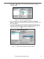
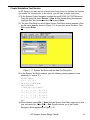
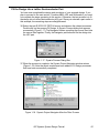
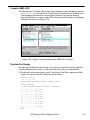
5. Double-click on Virtual Device. You will see the Choose Device pop-up window.
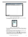
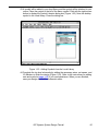
Select ISP Synario Device list in the Device Kit field. A device list appears
(Figure 1-4).
Figure 1-4. Choose Device Window
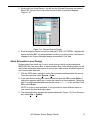
6. Scroll through the device list until you find ispLSI 2032-150 TQFP44. Highlight this
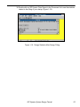
device and click OK. You will be asked to confirm your choice since it will result in
changes in the Project Navigator design environment. Click Yes.
Add a Schematic to your Design
Design projects are made up of one or more sources, which can be schematics,
ABEL-HDL files, test vector files, or documentation files. In the following steps you will
add a blank schematic sheet source to your project, add several schematic symbols,
and connect them with nets.
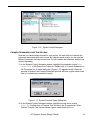
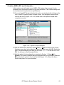
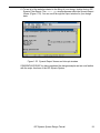
7. With the 2032 device selected, notice the processes associated with this source.
From the menu bar, select Source ⇒ New...
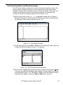
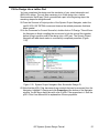
8. In the New Source dialog box, select Schematic and click OK or press Enter. A
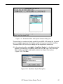
dialog box appears asking you to enter the name for a new schematic. Select the
path: c:\synplsi\examples and enter the file name demo.sch in the text field. Click
OK or press Enter.
NOTE: In order to avoid problems, it is a good idea to use a different name for
your source file than the project name.
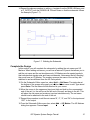
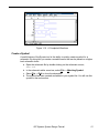
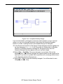
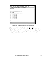
9. The schematic editor appears with a blank schematic (Figure 1-5). From the menu
bar, select Add ⇒ Symbol.
ISP Synario System Design Tutorial
13