1
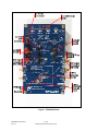
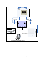
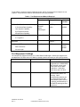
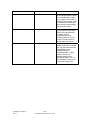
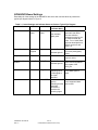
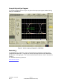
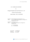
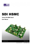
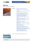
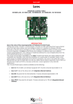
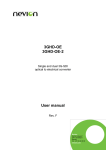
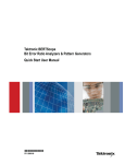
SD346EVK
LMH0346SQ SDI Reclocker
Evaluation Board User
Guide
National Semiconductor
EVK User Guide
Introduction
The LMH0346SQ Serial Digital Interface (SDI) Reclocker is designed to recover a clean clock from a
serial digital video signal which may be contaminated by jitter and to resynchronize the input video data to
the recovered clean clock. The LMH0346SQ SDI Reclocker accepts signals conforming to standards
SMPTE 259M (C), SMPTE 292M, and SMPTE 424M.
The SD346EVK is a PC board designed to aid in the evaluation of the performance characteristics of the
LMH0346SQ Reclocker. The SD346EVK PC board is fabricated with FR-4 PC board material. The
inputs and outputs of the LMH0346SQ are connected to the SMA coaxial connectors on the board using
controlled-impedance 50Ω single-ended and 100Ω differential PC board traces.
This instruction guide describes the features of the SD346EVK. It should be used in conjunction with the
LMH0346SQ SDI Reclocker data sheet. Schematics and Bill of Materials (BOM) for the SD346EVK
board are included separately. In addition, board fabrication files are available on request. Contact your
local National Semiconductor representative.
PC Board Features
The SD346EVK is shown in Figure 1. The features of the board are described in the sections that follow.
General Description
The SD346EVK is a four-layer PC board fabricated using FR-4. The layer stackup is shown in drawing
number 551600090-001. As the drawing indicates, the nominal board thickness is .062 inches. The
board includes internal ground and power supply planes. The ground plane is the second layer of the
board (underneath the top layer) and is the reference for the controlled-impedance traces on the top layer.
The SD346EVK is fabricated using Pb-free solder and components and is comprised of RoHS-compliant
materials.
SDI Input and Output Connectors
The SDI input and output connectors are 50Ω SMA female coaxial connectors (jacks). These connectors
will mate non-destructively with 50Ω SMA male coaxial connectors (plugs). They will also mate nondestructively with 50Ω APC-3.5 male coaxial connectors and 2.92 mm (K) male coaxial connectors.
These connectors will NOT mate to 2.4 mm connectors. Do not attempt to connect 2.4 mm connectors to
the SD346EVK PC board. This will damage both the board and the connected device or cable.
SD346EVK User Manual
Rev 1.0
1 of 10
© 2008, National Semiconductor Corp.
Figure 1. SD346EVK Photo
SD346EVK User Manual
Rev 1.0
2 of 10
© 2008, National Semiconductor Corp.
Although the SMA coaxial connectors are ruggedized for attachment to the edge of the SD346EVK PC
board, they can be damaged by over-tightening them. A standard SMA torque wrench with a torque
limitation of 7-10 in-pounds should always be used to connect cables to the connectors on the
SD346EVK. Do not allow heavy cables to hang unsupported from the connectors as they may break off
the board.
The SDI input and output connectors occur in pairs as the input and the outputs of the LMH0346SQ SDI
Reclocker are differential. The outputs of the LMH0346SQ SDI Reclocker are internally terminated. The
input to the LMH0346SQ Reclocker is externally terminated on the SD346EVK board with a 100Ω
differential resistor.
The SD346EVK has two sets of outputs connected to the two outputs of the LMH0346SQ SDI Reclocker.
The first set of outputs, labeled SDO, always carry the digital video data signal unless they are muted. If
the Reclocker is locked and not bypassed, these outputs carry a reclocked version of the input signal. If
the Reclocker is unlocked or bypassed, these outputs carry an unmodified replica of the input signal. The
outputs may be muted by the output mute control described in a later section.
The second set of outputs of the SD346EVK, labeled SCO/SDO2, can be set either to output a copy of
the data on the first set of outputs, either reclocked or not as described above, or to output the recovered
clock signal from the LMH0346SQ SDI Reclocker. The clock signal is only available when the
LMH0346SQ SDI reclocker is locked to a valid input signal.
The inputs and outputs of the SD346EVK PC board are AC-coupled with 4.7 µF 0603-size coupling
capacitors. These capacitors are rated for 6.3 VDC working voltage. The inputs and outputs of the
SD346EVK board may be terminated in any DC voltage that does not exceed this 6.3 V limit relative to
the negative power supply. The coupling capacitors may be replaced with 0603-size 0Ω resistors for DCcoupled evaluation.
DC Power Connectors
DC power is applied to the SD346EVK by means of standard .175-inch diameter binding posts. Three
power supply terminals are provided. The first is a common ground, to which the negative supply voltage
should be connected. This is the black binding post on the board. The two red binding posts on the
board are meant to provide 3.3 VDC to 1) the LMH0346SQ SDI Reclocker alone, and 2) the remainder of
the circuitry on the SD346EVK board. The dual-supply configuration permits measurement of the current
drawn by the LMH0346SQ SDI Reclocker independent of the other devices on the board if desired. The
two supplies may be connected together if desired using either an external jumper or the onboard header
between the 3.3 V power supply terminals.
The power supply is not regulated on the SD346EVK board so the effects of power supply variations can
be evaluated. It is recommended that the maximum supply voltage rating of the LMH0346SQ (4 VDC)
not be exceeded.
Controls and Indicators
The control lines of the LMH0346SQ SDI Reclocker can be controlled by various means using the
SD346EVK. The primary method for controlling these lines is the DIP switches located on the
SD346EVK board. The DIP switches are labeled according to their function. When the switch actuator is
pushed to the right (seen from the top), the switch is closed. The schematic for the board indicates the
functions of each switch. The switch functionality is summarized in Table 1.
Two headers are also provided for operating the control lines of the LMH0346SQ SDI Reclocker. The
first is located immediately below the DIP switches. This header is meant to be used with two-pin
jumpers and provides parallel functionality to the DIP switches. When a jumper is installed on the header
it overrides the function of the equivalent DIP switch.
The second header is located to the right of the DIP switches. This header is meant to provide access for
remote control of the LMH0346SQ SDI Reclocker. When this header is used the DIP switches should all
be set in the open position and no jumpers should be installed on the control header. The connections for
this header are described in the schematic for the SD346EVK PC board. It is recommended that this
SD346EVK User Manual
Rev 1.0
3 of 10
© 2008, National Semiconductor Corp.
header only be used for advanced control applications and only by users familiar with the operation of the
LMH0346SQ SDI Reclocker.
LED indicators are provided near the top of the board to indicate the state of the control inputs and the
indicator outputs of the LMH0346SQ SDI Reclocker. The LED states and their meanings are
summarized in Table 1.
Table 1. Control and Indicator Function Summary
Function
Rate Select
Bypass/Autobypass
Switch
Rate0
Rate1
Indicator
Rate0
Rate1
Bypass/Autobypass
Bypass
Switch “On”
Function and
Indication
Switch “Off”
Function and
Indication
Rate line pulled
to logic 1
Rate line pulled
to logic 0
Indicator light
turns red
Indicator light
turns green
LMH0346SQ
reclocker forced
to bypass mode
LMH0346SQ
reclocker in
normal
(autobypass)
mode
Indicator on
(red)
Indicator off
Output Mute
O P Mute
None
LMH0346SQ
reclocker output
is muted
LMH0346SQ
reclocker output
is active
Serial Clock Output
Enable
SCO_EN
SCO_EN
Second output
of the
SD346SQEVK
outputs the
recovered clock
Second output
of the
SD346SQEVK
outputs a copy
of the reclocked
data
Indicator on
(green)
Indicator off
SD/HD Indication
None
SD_HD
Indicator green
indicates HD or
3 Gbps signal
or no signal
detected
Indicator red
indicates SD
signal detected
Lock Detection
None
LOCK DET
Indicator green
when the
LMH0346SQ
reclocker is
locked to the
incoming signal
Indicator red
when the
LMH0346SQ
reclocker is not
locked to the
incoming signal
SD346EVK User Manual
Rev 1.0
4 of 10
© 2008, National Semiconductor Corp.
There is also a header on the right side of the SD346EVK board which is connected to the SD/HD
indication of the LMH0346SQ SDI Reclocker. It is meant to control an LMH0302 SDI cable driver. The
output polarity of the signal on this header is such that it can be connected directly to the SD/HD control
input of the LMH0302 cable driver. The header on the SD346EVK board facilitates this connection.
27 MHz Reference
The SD346EVK includes an on-board 27-MHz reference crystal. In the normal configuration of the board
this crystal is active. The LMH0346SQ SDI Reclocker includes a crystal driver circuit that produces the
27-MHz reference clock using this crystal.
The SD346EVK also includes a connector for inputting an external 27-MHz reference if desired. In order
to disable the on-board crystal a 0Ω resistor indicated on the schematic for the board must be removed.
This permits evaluation of the operation of the LMH0346SQ SDI Reclocker with an external reference.
SMBus Connector
The LMH0346SQ SDI Reclocker can be controlled via a 2-wire bus very similar to the standard SMBus.
This mode of operation was designed for factory use only.
Typical Output Waveform
A test waveform can be readily generated and used to verify proper operation of the SD346EVK. In order
to generate this output waveform, the following setup procedure should be used.
Test Setup
The test setup used for testing the SD346EVK board is shown in Figure 2. Note that the test setup
includes a SyntheSys Research BERTScope as a signal generator, eye diagram measurement device,
and bit error rate test receiver. Other equivalent instruments could be used for these measurements.
The equipment used for testing the SD346EVK is listed in Table 2.
SD346EVK User Manual
Rev 1.0
5 of 10
© 2008, National Semiconductor Corp.
UTIFlex Cable
CK+ CK-
BERTScope
Clock In
Clock Out
Data Out
Data In
Data+ Data-
Data+ Data-
UTIFlex Cable
UTIFlex Cable
UTIFlex Cable
SD346SQ EVK Board
SDI
SDO
SDI
SDO
UTIFlex Cable
SCO
UTIFlex Cable
SCO
VCC_IC VCC
3.3 V
GND
SMBus
+
GND
RF
In
HP E3610A DC Power
Supply
SMBus Controller Cable
HP8593E Spectrum
Analyzer
`
PC with SMBus Controller and Serial Port
Figure 2. Test setup for the SD346EVK board.
SD346EVK User Manual
Rev 1.0
6 of 10
© 2008, National Semiconductor Corp.
To generate the example output eye diagram shown, the PC and the spectrum analyzer are not
required. These items are used for other elements of the test procedure.
Table 2. Test Equipment and Material Required
Suggested Equipment
Description
Manufacturer
Bit Error Rate Test Set with the following:
Model
Number
BERTScope
12500B
J-Bert
N4903A
Hewlett-Packard
DC Power Supply
E3610A
Spectrum Analyzer with minimum 3 GHz
bandwidth
Hewlett-Packard
Portable Spectrum
Analyzer
8593E
Six (6) each UTIFlex coaxial cables
Micro-Coax Inc.
UTIFlex
UFB205A0-0360000000
3 Gb/s Serial Data Capability
SyntheSys
Research
Equipment Name
Agilent
Technologies
Jitter Injection Capability
Eye Diagram and Jitter
Measurement Capability
DC Power Supply
3.3 V @ 0.5 A
SMA connectors
36 inch length
Test Equipment Settings
The example eye diagram shown is for a 1.4835 Gb/s HD SDI signal. Similar eye diagrams can
be obtained at 2.97 Gb/s and at 270 Mb/s by changing the bit rate setting on the signal generator.
Generator Setting
Value
Comments
Data Rate
1.4835 Gb/s
Any valid SMPTE data rate
supported by the LMH0346SQ
SDI reclocker can be used.
These rates are 270 Mb/s,
1.485 Gb/s, 1.4835 Gb/s,
2.967 Gb/s, and 2.97 Gb/s
Data Pattern
PRBS-7
This is a standard
pseudorandom pattern 127
bits long. Other
pseudorandom patterns can
be used as well as live SDI
video patterns (which are not,
in general, pseudorandom) or
the SMPTE pathological data
sequences.
SD346EVK User Manual
Rev 1.0
7 of 10
© 2008, National Semiconductor Corp.
Generator Setting
Value
Comments
Output Amplitude
200 mV
This is the specified lower limit
for the input differential voltage
for the LMH0346SQ. Higher
input voltages can be used. A
differential input voltage of 200
mV peak-to-peak means that
each of the two inputs swings
100 mV peak-to-peak.
Output Offset
0V
The inputs of the SD346EVK
are AC coupled so the output
offset of the generator does
not matter unless it
overstresses the input
coupling capacitors. Do not
exceed 4 V output offset on
the generator to avoid this.
Injected Jitter
0 UI
If the signal generator is
capable of injecting controlled
jitter, the jitter tolerance of the
LMH0346SQ may be
evaluated using the
SD346EVK board. Typical
settings used for jitter
tolerance testing on the
SD346EVK board are 0.7 UI
jitter amplitude at 5 MHz and
10 MHz jitter frequencies.
SD346EVK User Manual
Rev 1.0
8 of 10
© 2008, National Semiconductor Corp.
SD346EVK Board Settings
Essentially all of the settings of the SD346EVK are set to their nominal values to produce the
typical eye diagram shown in Figure 3.
Table 3. Control Settings and Indicator States to Produce Typical Eye Diagram
Function
Switch
Indicator
Switch and
Comments
Indicator State
Rate Select
Rate0
Rate1
Rate0
Rate1
Both switches off
Bypass/Aut
obypass
Bypass
Switch off
Output Mute
OP Mute
None
Switch off
LMH0346SQ Reclocker
output is active.
Serial Clock Output
Enable
SCO_EN
SCO_EN
Switch off
This test will produce the
same results regardless
of the state of the
SCO_EN.
SD/HD Indication
None
SD_HD
Indicator green,
indicating HD or
3 Gb/s signal or
no signal
detected
The indicator will be red if
a 270 Mb/s signal is
used.
Lock Detection
None
LOCK DET
Indicator on
(green),
indicating that the
LMH0356
Reclocker is
locked to the
incoming signal
The indicator will be off if
a non-supported data
rate is used.
Bypass/Autobypass
SD346EVK User Manual
Rev 1.0
Both indicator
lights green
Indicator light off
Indicator light off
9 of 10
© 2008, National Semiconductor Corp.
This is the setting for
automatic rate detect.
The rate selection
switches can also be set
to match the data rate
input. For a 1.4835 Gb/s
signal as described here,
Rate 0 can be off and
Rate 1 on.
LMH0346SQ Reclocker
in normal (autobypass)
mode.
Sample Output Eye Diagram
The output eye diagram shown in Figure 3 is typical of the output eye diagrams obtained during
testing of the SD346EVK.
Figure 3. Typical output eye diagram for 1.4835 Gb/s.
Summary
The SD346EVK is a simplified four-layer PC board designed to facilitate the evaluation of the
LMH0346SQ SDI Reclocker. In concept it is a simple input/output board with the LMH0346SQ
SDI Reclocker in the signal path. This manual has described the features of the PC board and its
operation.
For additional information, please see:
www.national.com/sdi
SD346EVK User Manual
Rev 1.0
10 of 10
© 2008, National Semiconductor Corp.
IMPORTANT NOTICE
Texas Instruments Incorporated and its subsidiaries (TI) reserve the right to make corrections, modifications, enhancements, improvements,
and other changes to its products and services at any time and to discontinue any product or service without notice. Customers should
obtain the latest relevant information before placing orders and should verify that such information is current and complete. All products are
sold subject to TI’s terms and conditions of sale supplied at the time of order acknowledgment.
TI warrants performance of its hardware products to the specifications applicable at the time of sale in accordance with TI’s standard
warranty. Testing and other quality control techniques are used to the extent TI deems necessary to support this warranty. Except where
mandated by government requirements, testing of all parameters of each product is not necessarily performed.
TI assumes no liability for applications assistance or customer product design. Customers are responsible for their products and
applications using TI components. To minimize the risks associated with customer products and applications, customers should provide
adequate design and operating safeguards.
TI does not warrant or represent that any license, either express or implied, is granted under any TI patent right, copyright, mask work right,
or other TI intellectual property right relating to any combination, machine, or process in which TI products or services are used. Information
published by TI regarding third-party products or services does not constitute a license from TI to use such products or services or a
warranty or endorsement thereof. Use of such information may require a license from a third party under the patents or other intellectual
property of the third party, or a license from TI under the patents or other intellectual property of TI.
Reproduction of TI information in TI data books or data sheets is permissible only if reproduction is without alteration and is accompanied
by all associated warranties, conditions, limitations, and notices. Reproduction of this information with alteration is an unfair and deceptive
business practice. TI is not responsible or liable for such altered documentation. Information of third parties may be subject to additional
restrictions.
Resale of TI products or services with statements different from or beyond the parameters stated by TI for that product or service voids all
express and any implied warranties for the associated TI product or service and is an unfair and deceptive business practice. TI is not
responsible or liable for any such statements.
TI products are not authorized for use in safety-critical applications (such as life support) where a failure of the TI product would reasonably
be expected to cause severe personal injury or death, unless officers of the parties have executed an agreement specifically governing
such use. Buyers represent that they have all necessary expertise in the safety and regulatory ramifications of their applications, and
acknowledge and agree that they are solely responsible for all legal, regulatory and safety-related requirements concerning their products
and any use of TI products in such safety-critical applications, notwithstanding any applications-related information or support that may be
provided by TI. Further, Buyers must fully indemnify TI and its representatives against any damages arising out of the use of TI products in
such safety-critical applications.
TI products are neither designed nor intended for use in military/aerospace applications or environments unless the TI products are
specifically designated by TI as military-grade or "enhanced plastic." Only products designated by TI as military-grade meet military
specifications. Buyers acknowledge and agree that any such use of TI products which TI has not designated as military-grade is solely at
the Buyer's risk, and that they are solely responsible for compliance with all legal and regulatory requirements in connection with such use.
TI products are neither designed nor intended for use in automotive applications or environments unless the specific TI products are
designated by TI as compliant with ISO/TS 16949 requirements. Buyers acknowledge and agree that, if they use any non-designated
products in automotive applications, TI will not be responsible for any failure to meet such requirements.
Following are URLs where you can obtain information on other Texas Instruments products and application solutions:
Products
Applications
Audio
www.ti.com/audio
Automotive and Transportation www.ti.com/automotive
Amplifiers
amplifier.ti.com
Communications and Telecom www.ti.com/communications
Data Converters
dataconverter.ti.com
Computers and Peripherals
www.ti.com/computers
DLP® Products
www.dlp.com
Consumer Electronics
www.ti.com/consumer-apps
DSP
dsp.ti.com
Energy and Lighting
www.ti.com/energy
Clocks and Timers
www.ti.com/clocks
Industrial
www.ti.com/industrial
Interface
interface.ti.com
Medical
www.ti.com/medical
Logic
logic.ti.com
Security
www.ti.com/security
Power Mgmt
power.ti.com
Space, Avionics and Defense
www.ti.com/space-avionics-defense
Microcontrollers
microcontroller.ti.com
Video and Imaging
www.ti.com/video
RFID
www.ti-rfid.com
OMAP Mobile Processors
www.ti.com/omap
Wireless Connectivity
www.ti.com/wirelessconnectivity
TI E2E Community Home Page
e2e.ti.com
Mailing Address: Texas Instruments, Post Office Box 655303, Dallas, Texas 75265
Copyright © 2012, Texas Instruments Incorporated
Mouser Electronics
Authorized Distributor
Click to View Pricing, Inventory, Delivery & Lifecycle Information:
Texas Instruments:
SD346EVK