1
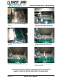
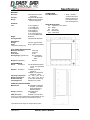
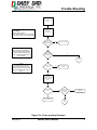
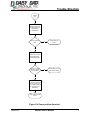
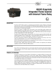
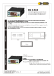
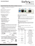
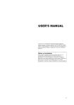
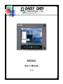
4823AC
User’s Manual
V. 1.0
Disclaimer & FCC Warning
DISCLAIMER
Daisy Data Displays, Inc. makes no representations or warranties with respect to the
contents or use of this manual, and specifically disclaims any express or implied warranties of merchantability or fitness for any particular purpose. Further, Daisy Data Displays, Inc. reserves the right to revise this publication and to make changes to its content, at any time, without obligation to notify any person or entity of such revisions or
changes.
Further, Daisy Data Displays, Inc. makes no representations or warranties with respect
to any Daisy Data Displays manufactured equipment, and specifically disclaims any
express or implied warranties of merchantability or fitness for any particular purpose.
Further, Daisy Data Displays, Inc. reserves the right to make changes to any and all
Daisy Data Displays manufactured equipment, at any time, without obligation to notify
any person or entity of such changes.
FCC WARNING
Computing devices and peripherals manufactured by Daisy Data Displays generate,
use, and can radiate radio frequency energy, and if not installed and used in accordance with the instructions in this manual may cause interference to radio communications. Such equipment has been tested and found to comply with the limits for a Class
A computing device pursuant to Subpart J of Part 15 of the FCC Rules, which are designed to provide reasonable protection against radio interference when operated in a
commercial environment. Operation of this equipment in a residential area is likely to
cause interference, in which case the user - at his own expense - will be required to
take whatever measures may be required to correct the interference.
Some components may not have been manufactured by Daisy Data Displays, Inc. If
not, Daisy has been advised by the manufacturer of the component that the component
has been tested and complies with the Class A computing device limits as described
above.
Copyright 2008 Daisy Data Displays, Inc. All rights reserved. No part of this publication may be reproduced, photocopied, stored on a retrieval system, or transmitted
without express prior written consent.
Daisy Data Displays, Inc.
2850 Lewisberry Road
York Haven, PA 17370 USA
Phone: (717) 932-9999
www.3inc.net
March 2012 Edition
Manual Revision 1.0
3/26/2012
4823AC User’s Manual
i.
Limited Warranty
Limited Warranty and Liability Statement
To the original purchaser, Daisy Data Displays, Inc., hereinafter referred to collectively
as SELLER, warrants each of its manufactured products, and all components therein
contained to be free from defects in materials and/or workmanship for a period of 12
months from the date of purchase.
Should a malfunction, or other indication of defect attributable directly to faulty materials and/or workmanship occur, Seller will, at its option, and without charge to the customer for labor and parts, repair or replace the defective product, F.O.B. Seller’s plant,
but Seller will not be responsible for freight from Purchaser to Seller’s plant.
In no event shall Seller be liable for any loss, inconvenience or damage, whether direct,
incidental, consequential or otherwise resulting from abuse, misapplication or modification of the product, improper or faulty power, damage resulting from repairs or alterations performed by unauthorized persons, or conditions resulting from any other equipment attached to the product.
Seller assumes no liability for damage occurring in transit due to the product not being
returned in its original shipping material.
This warranty is exclusive and is in lieu of any warranty of merchantability or fitness for a particular purpose or other warranty of quality whether expressed or
implied, except of title and against patent infringement. Correction of nonconformities, in the manner and for the period of time provided above, shall constitute fulfillment
of all liabilities of the Seller to the Purchaser with respect to, or arising out of the goods,
whether based on contract, negligence, strict tort or otherwise.
LIMITATION OF LIABILITY: The Seller shall not under any circumstances be
liable for special or consequential damages, such as, but not limited to, damage or loss
of other property or equipment, loss of profits or revenues, cost of capital, cost of purchased or replacement goods, or claims of customers of Purchaser for service interruptions. The remedies of the Purchaser set forth herein are exclusive, and the liability of
Seller respect to any contract, or anything done in connection therewith such as the
performance or breach thereof, of from the manufacture, sale, delivery, resale, installation or use of any goods covered by or furnished under this contract whether arising out
of contract, negligence, strict tort or breach of warranty or otherwise, shall not, except
as expressly provided herein, exceed the price of the goods upon which such liability is
based.
This warranty gives you specific legal rights, and you may also have other rights, which
vary from state to state.
Seller makes every effort to provide clear and accurate technical information on the application of its products in the Operator's Manual, and assumes no liability for misuse of
the information.
3/26/2012
4823AC User’s Manual
ii.
Power and Signal Requirements
Power and Signal Requirements
Mounting Location
When mounting, Human Machine Interfaces (HMI) and Purge systems must be positioned to avoid radiated and induced interference. Do not mount the unit in close proximity to a device that generates strong radiofrequency interference or electromagnetic
interference. HMI and Purge systems must be also positioned to avoid exposure to excessive heat. Do not mount the unit in close proximity to a steam line, heated vat or
oven.
Gland Plates
Before modifications can be made, Gland Plates must be removed. Please note that
metal shavings are detrimental to electronic systems.
Machining
Only make enclosure penetrations in designated locations. All metal shavings must be
collected and removed.
Wiring Requirements
AC power inputs require dedicated circuits or feeds. Power from lines or circuits
shared by motors, drives, welders, arc furnaces, or inductive lighting is not acceptable.
Conduits for HMI and Purge power should be separated from other conduits to prevent
radiated or induced interference. Devices that produce spikes, surges, and brownouts
are detrimental to computers, and can corrupt data and interfere with purging systems.
Do not use a transformer or other device to step down a three phase circuit to run a
HMI or Purge System.
Communication wires and signals should be run in separate conduits and routed away
from power conduits. Providing isolation to prevent emissions from other conduits is
essential to data integrity. Long runs of parallel signal lines can cause “cross-talk” and
corrupt data making communications unreliable or impossible.
DC power should be provided by a dedicated power source. If multiple units must be
powered from a single DC supply, the power cables must be run directly from the unit
to the supply. Chaining power from one unit to the next is unacceptable. Units can interfere with each other by developing noise due to the resistance of the wires. The filtering is provided by the source or power supply.
Additional Wiring
It is not permitted to run wiring through the unit that is nonessential to the unit. The
cabinet is not a junction box.
Adding Additional Equipment
Installing additional equipment in units approved for hazardous classed environments
violates the approval of the unit.
3/26/2012
4823AC User’s Manual
iii.
Table of Contents
Table of Contents
Disclaimer
…………………………………………….………………………………..i
FCC Warning ………………………………………...….………….……………………..i
Limited Warranty and Liability Statement …………….………...……………………..ii
Power and Signal Wiring Requirement ………………………………………………...iii
Table of Contents …..…………………………………….………………...…………….iv
Front Door Callout ..…………………………………………………………….……………….1
Enclosure Sides Callout ………………………….………………………………………….2
Enclosure Gland BoxCallout……..……………………………………………………………..3
Inside Door Callout …..………………………………….……………………………………...4
Inside Enclosure Callout ...………………………….………………………………………..5
PCI Card Retainer Assembly…………………………………………………………………...6
Specifications ..…………………………………………………………………………………..7
Trouble-Shooting …..……………………………………………………………………………8
Maintenance and Cleaning………………………………………………….…………………10
Replacement Parts List.…...…………………………………………………………………..12
Schematic & Block Diagram......…..…………………………………………………………..13
Drawing …....…………………………………………………………………………………..14
3/26/2012
4823AC User’s Manual
iv.
Front Door Callout
2
1
4
3
5
Figure 1. Front View
1. Door
4. Display
2. Touch Screen
5. Keypad
3. Latches
Figure 2.
Unlocked Latch
Figure 3.
Locked Latch
Figure 4. Keypad
3/26/2012
4823AC User’s Manual
1
Enclosure Callout
1
2
1
Figure 5. Top View
1. Accessory Mounting Holes (¼ - 20 threads)
2. Serial Identification Label (DO NOT REMOVE)
Figure 6. Latch side
3
3
Figure 7. Rear View
3. Accessory Mounting Holes (¼ - 20 threads)
3/26/2012
4823AC User’s Manual
2
Gland Plate Callout
Figure 8. Gland Plate
1
2
3
Figure 9. Recessed Connector Panel
1. 120 Volts AC Input
2. Network Input
3. Adjustable Cableway
3/26/2012
4823AC User’s Manual
3
Inside Door Callout
1
5
9
8
7
10
2
3
11
4
12
6
Figure 11. Door Interior
1.
2.
3.
4.
5.
Door Assembly
Backlight Inverter
Lamp Voltage Cables
Keypad Assembly
Backlight Power/Control
Signal Cable
6. Touch Screen Controller
7. Touch Screen Power/Data
Cable
3/26/2012
8. USB Keypad Cable
9. 0-6º Thermostat (for ATX
power supply)
10. 8-16º Thermostat (for all
heaters)
11. Touch Screen Ribbon Cable
12. Keypad Controller Board
4823AC User’s Manual
4
Inside Enclosure Callout
2
1
3
7
4
8
5
9
10
6
11
Figure 12. Enclosure
1.
2.
3.
4.
5.
6.
3/26/2012
Motherboard Cage
Flash Drive Assembly
CD Drive Power Connector
Power Supply Assembly
CPU Reset Switch
Thermostat (for fin fans under power supply)
7. PCI Card Retainers (see pg. 7
for assembly instructions)
8. PCI Expansion Slots (2)
9. Peripheral Component Interconnect (PCI)/USB label
10. I/O Ports Label
11. Fin Cooling Fans
4823AC User’s Manual
5
PCI Card Retainer Assembly
1. Loosen thumb screws on CPU cage.
(Qty. 4)
2. Remove 2 #6 nuts from studs.
3. Place card into bracket and slide stud
assembly to about .50” from end of card.
4. Tighten thumb screws to lock PCI card
in place.
5. Place single or double card bracket
onto stud assembly and secure with 2
#6 nuts.
6. Angle clip bracket and attach to PCI
card end. (Clip will snap tightly onto card)
7. Slide clip bracket over flush to card
and secure with thumb screw. (Locktite
in place to secure)
***MULTIPLE CARD AND CLIP BRACKETS SHOULD BE USED TO BETTER RETAIN
THE END OF THE CARD FOR SHOCK AND VIBRATION. LOCATION AND
NUMBER OF BRACKETS TO BE DECIDED UPON BY CUSTOMER NEEDS.
3/26/2012
4823AC User’s Manual
6
Specifications
MATERIAL
Enclosure
Cast Aluminum Powder
Coat Finish
Polycarbonate Standard
NEMA 4X Non-incendive
electrical equipment
Viewport
Design
PHYSICAL
15.0”
Weight
Viewing Window
ELECTRICAL
Voltage
Power
*Computer & display only
15.50” Height (H1)
17.50” Width (W)
14.50” Height (H2)
8.56” Depth (D1)
1.56” Depth (D2)
9.16” View Height (VH)
12.16” View Width (VW)
60-65 Lbs.
Polycarbonate Standard
ENVIRONMENTAL
Shock
IEC68 2-27
Vibration
IEC68 2-6
Operating Temperature
Storage Temperature
Relative Humidity
Listed Approvals
1 Serial, 1 Parallel,
4 USB, Audio In/Out,
Network, Game Port
PS/2 Keyboard Port,
PS/2 Pointing Device
AVAILABLE OPTIONS
451 Capacitive Touch Screen
820 Bezel
821 Sun Visor
823 Windows XP
9137 Yoke Mount
120 VAC @ 3.35 Amps
90 W* (402 W w/ heaters)
FLAT PANEL SPECIFICATIONS
Maximum Resolution
Dot Pitch
Color Depth
Viewing Angle (Typical HxV)
Brightness (Standard)
CONNECTIONS
From Motherboard
1024x768
0.297mm
24 bit
80° Left & Right
x 80° Up & 60°
Down
600 nits
15G bi-directional impulse
11 msc, non operational
3 axes
3 GRMS operational,
5-2000 Hz
5 GRMS non-operational,
5-2000 Hz, 3 axes
-40° - 150° F (-40° - 65° C)
-40° - 150° F (-40° - 65° C)
10-95% Non-Condensing
EExnA IIC T4, ExII36
COMPUTER SPECIFICATIONS
Motherboard
Mini-ITX SBC, Integrated
Graphics, 2 PCI Slots
Dual 10/100 Base-T
Network Interface
Storage (Standard)
4GB Flash Drive,
1GB Ram
CPU (Standard)
Pentium™ M 1.8 GHz
Contact your Daisy Data Displays representative for info.
on the latest CPU, memory, and hard drive options.
*Specifications are subject to change without notice.
3/26/2012
4823AC User’s Manual
7
Trouble-Shooting
The computer will not
start
Power Requirements
Model 4823AC
Nominal Voltage 120VAC
Current (Warm Climate) .75 Amps Nominal
Current (Cold Climate) 3.35 Amps Nominal
Verify power source.
(See model
requirements)
Can the
power source meet
the requirements?
Note 1
The computer is not permitted to
start if the temperature drops below
0 Celsius inside the cabinet and will
remain off until the temperature rises
above 6 Celsius.
No
Correct power system.
Yes
Is the
temperature
in the unit below 0
Celsius? *See note
1
No
Manual
start
Yes
Note 2
The heaters turn on when the
internal temperature drops below 8
Celsius and will remain on until the
internal temperature rises above 16
Celsius.
Are the heaters
warm?
No
Heater thermostats may
be bad
Yes
Wait until the
temperature inside the
unit warms above 0
Celsius
Yes
Did the computer
start?
No
Is the power good
from the Surge
Suppressor?
No
Replace Surge
Suppressor
Yes
Yes
This is normal operation
for a cold climate
Manual
start
Figure 13a Power problem flowchart
3/26/2012
4823AC User’s Manual
8
Trouble-Shooting
Manual
start
Open the cabinet door
and press the PowerReset buttons
simultaneously
Did the computer
start?
No
Contact factory for
service
No
CMOS battery may be
dead. Replace battery
Yes
CMOS may have lost
BIOS setting data.
Correct BIOS settings.
Does the computer
start when external
power is applied?
Yes
A brownout from the
power source may have
caused a glitch in the
power system resulting in
the corruption of the
CMOS data.
Verify quality of power
source.
Figure 13b Power problem flowchart
3/26/2012
4823AC User’s Manual
9
Maintenance and Cleaning
Maintenance and Cleaning
While D3’s products are designed to be durable and dependable, certain parts need to
be maintained and cleaned occasionally. This will help to keep units operating at full
potential.
Conductive dust or buildups of liquids can affect capacitive touch screens. Touch
screens made from glass and polycarbonate can be cleaned with Isopropyl alcohol or
a 50/50 mix of Isopropyl and water. Apply solution onto a clean lint free cloth first. Do
not spray the cleaner directly onto the window. Ammonia based cleaners are not recommended. Live steam should not be used in the cleaning of the units. Solvents and
abrasives can damage anti-glare coatings. Scratches cannot be buffed out of touch
screens.
Elastomer keyboards and mice should be cleaned using a soft brush with mild soap
and water.
Stainless steel enclosures can be cleaned with just about any cleaner available but
care should be used if using solvents near gaskets and touch screens or viewing windows. Enclosures and external heat sinks should be kept clean and free of the accumulation of dirt, which can cause the buildup of heat and performance degradation.
3/26/2012
4823AC User’s Manual
10
Operation
Temperature < 8° C
Heaters Off
Heaters On
Temperature > 16° C
Temperature > 6° C
ATX Power Supply Off
ATX Power Supply On
Temperature < 0° C
Temperature > 28° C
Cooling Fans Off
Cooling Fans On
Temperature < 15° C
Figure 14 Thermostat Operation
Cold Temperature Delayed Start-Up
At low temperatures, this computer won’t turn on until the heaters are allowed to
bring the internal temperature up to 6°C. This may take up to 1 hour.
3/26/2012
4823AC User’s Manual
11
Replacement Parts List
HVAC Components
Part Number
P070-000433
I100-001809
I640-001503
E906-00068
I100-001800
I100-001801
I100-001813
Model Number: 4823AC
Description
110VAC Heater, Kapton 5”x10” 52.9 Ohms
Card Cage Cooler Fan Assembly
Cooling Fan Array Assembly (for Fins)
CPU Cooler Heatsink and Fan
Thermostat (0Y) –2PHSG 20”L
Dual Thermostat (8x&8x) –2PHSG
Thermostat (15Y0) –2PHSG 6”L
User Interface Components
Part Number
Description
I649-000038
Front Door Latch Kit
P040-000045
Touch Screen Capacitive Tough Touch (Optional)
P040-100022
Touch Screen Controller (Optional)
I301-000025
14-Key Membrane Keypad (Legend is customizable)
P000-000123
15” Transflective LCD Display
P070-000520
LCD Backlight Inverter Module
I640-001466-02
15” LCD Door Assembly (must specify touch screen option)
P030-000004
AC Filter 110VAC, 20A, TVSS Plug
P030-000005
I024-000013
I301-000035
AC Filter Base, DIN Rail Mount
Keypad Controller (must specify optional firmware)
CPU Power/Reset Membrane
Computer Components
Description
Part Number
I640-001497
P070-000505
P060-000061
I640-001518-01
I640-001502-01
Flash Drive Assembly with Mounting Panel and Adapter
Compact Flash to IDE Drive Adapter
4GB Compact Flash Drive (Blank)
110VAC Power Supply, 1U Form Factor, Potted
SBC Card Cage Assembly
I640-001519
P050-000230
A301-000018-01
A314-001024
I640-001504-01
SBC, Mini-ITX, Pentium-M, S479, Potted
PCI Riser Card
CPU Pentium-M 1.8Ghz
Memory, RAM, DDR 400, PC-3200, 1GB
PCI Card Retainer Kit
*Part Numbers subject to revision or change without notice.
3/26/2012
4823AC User’s Manual
12
Schematic & Block Diagram
3/26/2012
4823AC User’s Manual
13
Drawing
3/26/2012
4823AC User’s Manual
14