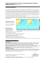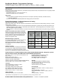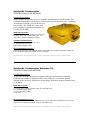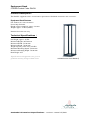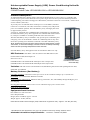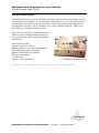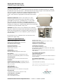
1
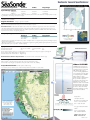
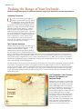
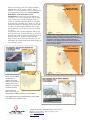
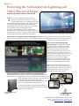
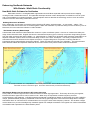
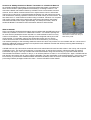
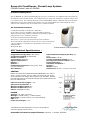
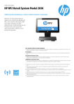
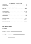
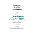
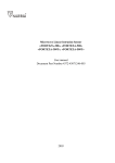
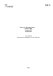
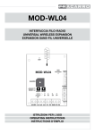
Continuous
Surface Current Mapping
& Wave Monitoring
System
See The Ocean From an Amazing Perspective
The SeaSonde HF radar system by CODAR Ocean Sensors is your solution for making continuous, wide-area ocean
observations. The SeaSonde will provide you with years of real-time data over large coverage areas, with ranges up to
200 km -- This is not possible with any other technology!
The SeaSonde is a compact, non-contact surface current and wave measurement system that can be deployed and
maintained easily, and will perform even during extreme weather conditions such as hurricanes.
High Quality Data
CODAR Ocean Sensors' patented technologies, including our processing algorithms, allow the SeaSonde to produce
extremely accurate 2-D surface current velocity maps and meausres the most important wave parameters. Patented
antenna design and processing algorithms enable the system with up to 360º coverage. The patented pulsed FMCW
eliminates the range aliasing and antenna wind-vibration noise inherent to other HF system designs.
Focus on Your Application
The SeaSonde is an off-the-shelf tool that allows you to focus on applying the data rather than the technology of collecting it. Whether your work efforts involve guiding search and rescue operations, providing critical information to maritime vessels, or driving and improving numerical circulation models,
the SeaSonde will be an immense aid.
System Highlights:
Convenient: Nothing in the water: a truly non-contact
sensor. All hardware is located on the coast or an offshore structure. The patented compact antenna design
greatly simplifies siting requirements.
Reliable: All system hardware and software are developed by our own staff specifically for continuous, longterm field operations, and consistent data outputs.
Flexible: The software parameters are highly flexible,
yet designed to work smoothly, eliminating any need for
you to become a computer programmer or radar expert.
Automated: Data can automatically arrive at your
office at your preferred intervals, and can also be sent
directly to the Web for public viewing. †
Remote Access: Data retrieval, system monitoring,
parameter modifications and even factory support are all
conducted through system remote access. †
Low Power: SeaSondes' low power consumption allow
for working off-the-grid with alternative energy sources.
Cross-Platform Data Format: All data products are
stored as ASCII files for convenient data transfer to various computer platforms, incorporation into numerical
models and GIS programs.
Compatible with Coastal Culture: Where visual
impact and minimum land-use footprint are all important,
nothing beats the SeaSonde ultra-compact design.
† Communication Link Required
SeaSonde Configuration:
Standard
Hi-Res
Long-Range
Spatial Range (typical)
Alongshore:
20-60 km
15-30 km
100-220 km
Offshore:
20-75 km
15-20 km
140-220 km
• Ranges achieved vary with environmental conditions and antenna placement. Note: Two radars are normally required for creating 2-D surface current maps of direction and speed.
Range Resolution
500 m - 3 km
200-500 m
3-12 km
• Resolution is user selectable.
Angular Resolution:
1-5 degree grid: user selectable.
Current Accuracy: Varies with environment. Comparisons with ADCPs located in close proximity to the surface are typically < 7 cm/s of the total current velocity and 1-2 cm/s of the tidal component.
Wavefield Products (measured at each radar): Local on-shore wave conditions in ring centered ~3 km from coast around
each radar. Significant Waveheight: typical accuracy: 7-15%; Dominant On-Shore Direction: typical accuracy: 5 degrees -12
degrees; Dominant Wave Period: typical accuracy: 0.6 s; Other spectral wave parameters available. Wave information is limited
by environmental conditions and operating frequency.
Frequency Range (antennae tuned to operate at a frequency subband within):
Standard
Hi-Res
Long-Range
one of either:
one of either:
4.3-5.4 MHz
11.5-14 MHz or
24-27 MHz or
24-27 MHz
40-45 MHz
• Patented technology permits the simultaneous operation of multiple radars on a single frequency, thereby minimizing frequency
requirements and interference.
• Operators must adhere to their country’s radio communications regulations regarding radiated signal specifications, and receive
proper authorizations prior to operation. Consult company.
Courtesy of D. Musgrave,
U. Alaska Fairbanks
Equipment Dimensions:
SeaSonde Electronics
Transmit Antenna Height:
4.8 m for 11-14 MHz
Combined with RX
9m
Transmit Antenna Post
4m
N/A
N/A
Receive Antenna System (mast, dome loopstick antenna unit & vertical element atop dome) approx. total height 7m
Receive Chassis: 13H x 49W x 53D cm. Weight:14 kg
Transmit Chassis: 13H x 49W x 53D cm. Weight:15 kg
Maximum Distance Between Adjacent Radars: Recommend 40-60% of the radar's offshore range.
Power Requirements:
Either 120 VAC or 220 VAC, 50-60 Hz; total onsite electronics varies between 350
and 500 watts depending upon peripherals desired. [24 volt DC versions also available]
About CODAR
Output Radiated Power: 80 watts peak, 40 watts average
† For complete system specifications, please consult Technical Specification sheets available on company website.
Transmit
Antenna
Receive
Antenna
CODAR Ocean Sensors personnel are the inventors and
original developers of HF and
VHF radar technology for
ocean monitoring applications,
some having been in this field
for nearly 40 years. CODAR
staff continue to make
advancements in radar physics
theory as well as product
engineering refinements, and
apply them to ensure the
SeaSonde as the most reliable
HF radar system in the world.
The RiverSonde is their latest
product to enter the market,
and takes advantage of many
key SeaSonde features.
Headquarters:
1914 Plymouth Street
SeaSonde data integrated
into Google-based interface
created by Scripps Institute of
Oceanography (SIO).
Data courtesy of SIO.
Mountain View, CA 94043 USA
Phone: +1 (408) 773-8240
Fax: +1 (408) 773-0514
Toronga, 31 Madrid, ES-28043
SPAIN
Phone: +34 911263423
Fax: +34 911263424
email: [email protected]
Web: www.codar.com
VER-20100331
CODAR OCEAN SENSORS SeaSonde® Remote Unit System Specifications
Product Code: SSRS-100
SeaSonde Remote Unit Components†
• 1 Transmit Antenna Assembly (SSTA) & 1 Receiver Antenna Assembly (SSRA) OR,
!
1 Combined Transmit-Receive Antenna Assembly (SSTR) (avail. for frequencies 11.5 MHz and higher)
• 1 Transmit Cable & 1 Receive Antenna Cable Set OR,
!
1 Combined Transmit-Receive Antenna Cable Set (avail. for frequencies 11.5 MHz and higher)
• 1 SeaSonde Receiver Chassis (SSRX)
• 1 SeaSonde Transmitter Chassis (SSTX)
• 1 Radial Site Data Acquisition System (SSDA 100)
• 1 Electronics Interconnector Cable Kit
• 1 Set Operator Instruction Manuals, PDF format
• One Year Manufacturerʼs Warranty
† Base components only: review Remote Unit
Configuration Options inside this specification sheet.
Technical Specifications
RADIATED SIGNAL SPECIFICATIONS
Operators must adhere to local radiated signal regulations
and receive proper authorizations prior to operation.
Output Radiated Power: 80 W peak, 40 W average
Operating Frequency Range:
Receive Antenna (SSRA)
!
Electronics: 4.4 – 50 MHz
or
!
Antennas: Select from one of either:
Combined Transmit-Receive
!
4.4-6 MHz or
Antenna (SSTR)
!
11.5 - 14 MHz or
!
24-27 MHz or
!
40-45 MHz or
!
custom: any other frequency between 4.4-50 MHz
Modulation Format: Pulsed Swept Frequency CW
Sweep Width: 12-300 kHz (typical)
Pulse Repetition Frequency: 514 - 8224 Hz
Sweep Repetition Frequency: 1-4 Hz
Total Radiated Signal Bandwidth: (at -20dB level) 65-200
kHz
Polarization: Vertical
System Power Requirement (transmitter, receiver &
SSDA 100
computer): 350 watts (24V DC ver.) or 500 watts (120-220
VAC)
(SSTA)
SSTX
SSRX
RECEIVER
TRANSMITTER
Transmitter Chassis: SSTX
Input RF Drive Level: 0 dBm
Output RF Power Level: 100 watts peak, 50 watts average
Power Requirements: 300 watts;
!
(select one when ordering):
120 V AC, 50-60 Hz
220 V AC, 50-60 Hz
24 V DC
Design: (gated FET) modular; solid state
Operation: Class AB
Dimensions: (single chassis) 19” rack mountable, 3U tall;
13H x 49W x 53D (cm)
Weight: 15 kg
Temperature Range (ambient): 0˚ F (-18˚ C) to 90˚F (32˚ C)
Maximum Humidity: 80% non-condensing
SSRS-100 specification, v4, rev 03/2010
Receiver Chassis: SSRX
Maximum In-band Input Level: 0 dBm
Receiver Channel Impedance: 50 ohm
Sensitivity (noise level): -166 dBm in 1 Hz BW
Power Requirements: 100 watts;
!
(select one when ordering):
120 V AC, 50-60 Hz
220 V AC, 50-60 Hz
24 V DC
Design: modular, solid state, three-channel
Operation: I/Q homodyne
Output: USB digital output; digital data at 4096 16-bit/
second per channel
Dimensions: (single chassis) 19” rack mountable, 3U tall;
13H x 49W x 53D (cm)
Weight: 14 kg
[ Optional “SHARE” GPS synchronization Feature: GPS
assisted stability: >.0001 ppm and 50 nsec on PPS ]
Temperature Range (ambient): 0˚ F (-18˚ C) to 90˚F (32˚ C)
Maximum Humidity: 80% non-condensing
System Requirement: AC Power Conditioning via
Uninterruptable Power Supply (UPS). Minimum
recommended UPS capacity: 1500 VA (1050 Watt)
ANTENNA CABLING
Requirement- Cabling Protection:
Ideally cables between antennas and electronics are fed through protective conduit (such as 3.5 cm diameter PVC pipe) and
buried in trench. There are lower cost options available, but there will be greater risk to exposure and damage.
Transmit Cable
Type: Single Strand RG-8 Low loss Co-Ax, 75 m length
Receive Cable Set
Type: Quad strand RG-58 Low loss Co-Ax bundle, 100m
length
Combined Transmit- Receive Cable Set
(for 11.5 MHz and higher frequency bands)
Type: 1 x RG-8 + 2 x RG-58 Low-loss Co-Ax bundle,
Length: 75m (optional custom lengths available)
ANTENNA ASSEMBLY
Note: Antennas for operation at one frequency band and bandpass filters for operation at two frequency bands are included with
SeaSonde remote unit purchase. Antennas and filters for operation at additional frequency bands can be purchased separately.
Requirement- Bases/Mountings for Antennas:
Antennas need to be mounted vertically secured to concrete concrete pad (~ 1m x 1m 1m) or lashed/guyed to fencing or other
solid structure. Read SeaSonde Antenna Installation User's Guide for examples.
Receive Antenna Assembly
Consists of:
!
mast,
!
dome loopstick antenna unit &
!
vertical element (set atop dome)
Durability: All-weather
Total antenna height:
!
4.3 - 5.4 MHz: approx. 6.5 m
!
11.5- 14 MHz: approx. 6.5 m
Design: passive vertical monopole, two crossed loops into
preamplifiers
Functionality: omnidirectional, adjustable (in software) from
1-360 degrees
Transmit Antenna
Durability: All-weather
Total height:
!
4.4- 5.3 MHz: approx. 8.6 m
!
11.5-14 MHz: approx. 8.6 m
Transmitting Design: vertical monopole; omnidirectional
Combined Transmit-Receive Antenna Assembly
(for 11.5 MHz and higher frequency bands)
Consists of:
!
mast,
!
dome loopstick antenna unit &
!
vertical element (set atop dome)
Durability: All-weather
Total antenna height:
!
11.5- 14 MHz: approx. 8 m
!
24-27 MHz: approx. 6.5 m
!
40-45 MHz: approx. 5.5 m
Receiving Design:
!
passive vertical monopole, two crossed loops into
preamplifiers
!
omnidirectional, adjustable from 1-360 degrees
Transmitting Design: vertical monopole; omnidirectional
Requirement – SeaSonde Antenna Placement
Clear Space Around RX and TX Antennas
Objects that interact with or alter the response of the transmit or receive antennas
can affect bearing accuracy or create bearing gaps in coverage
• Position SeaSonde transmit or receive antennas one horizontal RADAR
wavelength or greater away from tall (one quarter of the RADAR wavelength or
taller) objects or obstructions (see chart below). Tree trimming/removal, or
relocation of other man made objects may be necessary.
• There should be no obstructions between the receive antenna and the seaward
side that may block energy in direction of ocean
• Position receive antenna one horizontal RADAR wavelength or greater away from
a cliff or building edge (see chart above). Requirement- Transmit Antenna Ground Plane Dimensions
The Long-Range (4.3-5.4 MHz) SeaSonde Transmit antenna requires a ground plane. If the antenna is attached to a metal
structure, such as on an oil platform or metal fence, then that object will act as the grounding device. If it is to be installed on a
beach, for example, then grounding elements will need to fan out from the base of the antenna towards sea. A minimum of 9
elements need to be placed in a 180º semi-circle on the seaward side of the antenna. Each element is a metal wire encased in
plastic (~1/8” diam.), whose length is about 7-8 m. These elements can be buried under sand or laid above ground.
Distance (Horizontal) from Water to Antennas
Antennas should be positioned close to the water to prevent propagation loss of energy traveling over ground. Maximum
recommended distance from transmit or receive antenna to water is four RADAR wavelengths (see above chart).
SSRS-100 specification, v4, rev 03/2010
RADIAL SITE DATA ACQUISITION SYSTEM (SSDA 100)
SSDA 100 Consists of:
!
Computer: select one of either mini-style or laptop computer
!
!
!
Monitor: color TFT
keyboard and mouse: USB, extended
Radial Suite Software License (individual site use)
Temperature Range: 0˚ F (-18˚ C) to 90˚F (32˚ C) for mini-style computer
Maximum Humidity: 80% non-condensing
Compatible Communications: 10/100/1000 Base-T Ethernet (RJ-45 connector) & Others (such as dial-up modem). Automatic
transfer of current, wave and diagnostic data products supported by software for dial-up lines and ethernet connections.
Communication Link Requirement
• A reliable data communications link is required for:
• Real-time data transmission,
• Real-time system monitoring,
• Proper system maintenance and customer support,
• Remote software updates.
• Minimum data bandwidth (upload and download each): 256 kbit/s.
Radial Suite Software Data Products
Radial Surface Current Velocity Maps
Radial Map Display: color monitor screen, archived ASCII vector files-formatted to CODAR's LLUV columnar table format (MatLab® loadable).
Spatial Range (typical): 20-220 km offshore; 20-220 km alongshore
Range Resolution: user selectable from 200 m - 12 km. Resolution is
based on transmit signal sweepwidth.
Angular Resolution: 1-5 degree grid: user selectable.
Current Accuracy: Varies with environment. rms typical for normal
environmental speed: < 7 cm/s of the total current velocity and 1-2 cm of
the tidal component, direction < 10 degrees.
Doppler Cross Spectra
Binary files of HF sea echo spectra for three receive channels (two crossloops & vertical element). Raw and averaged are available for processing
into radial vector maps.
Range Processed Spectra (Range Series)
Optional binary files of receiver range processing which can be processed
into Doppler cross spectra.
Raw I & Q voltages (Time Series)
Optional binary files of receiver analog measurements which can be
processed into range spectra and Doppler cross spectra.
Wave Field Parameters
Local on-shore wave conditions in ring centered 3km from coast around
each radar. Measurement range cell user-selectable.
Significant Waveheight. typical accuracy: 7-15%
Dominant on-shore Direction. typical accuracy: 5-12 degrees
Dominant Wave Period. typical accuracy: 0.6 s
Waveheight Energy vs. Frequency: ~0.01 Hz spacing
Dominant Wave Direction vs. Frequency: ~0.01 Hz spacing
Spectral Wave Frequency Range: 0.05 Hz - 0.25 Hz (20 s to 4 s periods)
Minimum Detectable Significant Waveheight: 1 m
Data Temporal Interval: User selectable. Typical wave averaging
performed over one hour
Wave History Displays: hourly waveheight vs. time. Hourly wave direction
vs. time. Hourly wave period vs. time
(Note: Wave information is limited by environmental conditions and
operating frequency. )
Diagnostics
ASCII or image of diagnostic time series data for system hardware,
software and data performance parameters. ASCII files are formatted to
CODAR's columnar table format (MatLab® loadable).
SSRS-100 specification, v4, rev 03/2010
SeaSonde Radial Software Suite
Functions:
• Real-time autonomous operation
• Real-time system monitoring, logging & alerts
(via email)
• Hardware
• Temperatures
• Voltages
• Data Acquisition
• Miscellaneous Hardware
• Software
• Applications/Tools running (relaunch if
not)
• Data collection & processing operations
• Acquisition and archiving
• Configuration done via Graphical User Interface
• Layered configurable properties for both basic
and advanced functions
• Graphical or command line control and
monitoring
• Visualization Software for all stages of data (raw
binary I & Q to vector maps) and diagnostics
• JPEG or PNG plot images for sharing via email
or web publishing
• Data archiving utility
• External Antenna Response Calibration &
Implementation
• Multiple levels of configurable Quality Control:
• Signal-To-Noise Computation &
Thresholding
• Peak Identification & Characterization
• Ship Echo Removal
• Burst Interference Removal (Lightning &
Others)
• Ionospheric Noise Removal
• Outlier Detection & Removal
2009 SeaSonde Remote Unit Configuration Options
Choose a primary frequency
band, then choose your options
Std: option part of standard configuration
N/C: option available at no extra charge
$: option available for a fee in addition to the base price
➡
Options
➡
Power Supply
(select one)
40 - 45
24 - 27
12 - 14
4-6
Custom
110 V (AC)
Std
Std
Std
Std
Std
220 V (AC)
N/C
N/C
N/C
N/C
N/C
24 V (DC)
$
$
$
$
$
Std
N/C
N/C
N/C
Std
N/C
N/C
Std
N/C
40-45 MHz
Second Rx Chassis
Filter Set
(select one)
24-27 MHz
Std
12-14 MHz
N/C
N/C
$
$
$
Std
$
N/C
N/C
Std
Std
N/C
Twin Transmit Antennas
$
$
$
Dual-Transmitter &
Twin Tx Antennas
$
$
$
GPS-enabled Frequency Multiplexing (SHARE)
Single Transmit Antenna
Antenna
Configuration
(select one)
Tx & Rx
Separate
Tx & Rx Combined
Tx/Rx Cable
Combine Tx/Rx
Antenna Only
(select one)
Rx Cable
1 X RG-8
2 X RG-58
4 X RG-58
Separate
Antennas Only
(select one)
3 X RG-8
Tx Cable
Separate
Antennas Only
Frequency Bands
1 X RG-8
(select one)
Std
Std
$
Consult
75 meters
Std
Std
$
Consult
price per meter
(beyond 75 meters)
$
$
$
$
$
100 meters
N/C
N/C
Std
Std
N/C
$
$
$
$
$
$
$
$
$
$
price per meter
(above 100 meters)
$
$
$
$
$
75 meters
N/C
N/C
Std
Std
N/C
price per meter
(above 75 meters)
$
$
$
$
$
$
$
$
$
$
Mini
Std
Std
Std
Std
Std
Laptop
$
$
$
$
$
SeaSonde Radial Suite
Std
Std
Std
Std
Std
Multi-Static Processing
$
$
$
$
$
$
$
$
$
$
price per meter
(above 100 meters)
100 meters
Extended Lightning Protection Kit
Computer Type
(select one)
Software
(single-use license)
Manufacturer’s Limited Warranty Extension
(annual price after first year)
SSRS-100 specification, v4, rev 03/2010
March 2009
Pushing the Range of Your SeaSonde
Hardware configuration options to expand the observable range of your SeaSonde, potentially beyond 300 km
Operating Frequency
O
ne easy way to achieve greater range is to
operate at a lower frequency band. This has
been known for decades, and is the reason
CODAR engineers designed the SeaSonde
for operation across a wide band, ranging from 4.4
MHz up to 50 MHz. The lowest of the SeaSonde
transmit frequency bands within 4.4 6 MHz
allows for greater ranges than the higher bands
without any increase in radiated power. In general,
the average daytime observable range achieved by a
SeaSonde operating near 46 MHz LongRange
mode is typically 160220 km. Actual coverage
varies on many factors, such as exact antenna
placement, sea conditions, external noise as well as
some userselectable software settings.
Twin Transmit Antennas
Another method for increasing observable range is
adding a second transmit TX antenna. A single
monopole antenna exhibits a uniform,
omnidirectional transmit signal pattern, meaning
that the radiated power is equally distributed across 360
degrees including sections over land. The simple addition of a second transmit antenna allows for beam control and
through proper orientation & phasing the antennas can direct more power transmitter signal power out towards sea. It is
most common for this conguration to be used on the lower SeaSonde bands 514 MHz, but is possible at any frequency.
This hardware conguration option is available when ordering a new SeaSonde Remote Unit or as a retrot. The ocial
name is Twin Transmit Antenna Conguration.
The directionality of the beam fan produced by the TX antenna pair can be controlled by adjusting the spacing between the
two elements. Spacing the two elements closer together will cause the signal strength to fan out, so that the power is
spread across a wider angle. As the two antennas are pulled apart, the resulting beam pattern becomes narrower, sending a
stronger signal out towards a more specic angular sector. This produces even greater range, but inside a narrower angle
sector. The antenna spacing and hence the TX beam fan spread is customized at the radar site and optimized for that
SeaSonde users goals.
Dual Transmitter - Twin Transmit
Antenna Configuration for
Maximum Range
SeaSonde
Coverage
to 334 km
Shown
A third way to extend range is to increase the
TX radiated power. However, when it comes
to increasing power, one quickly reaches the
point of diminishing returns on investment.
The SeaSonde transmitter output power is 40
watts average, which is low and also highly
practical from a design and results perspective.
Increasing the output power of a single
transmit power supply creates more internal
heat, placing more wear on itself and other
nearby parts inside the transmitter chassis.
Hence these other parts, including heat sinks,
must be upgraded to perform under this
greater heat stress. This drives the price of a
radar up to an uncomfortable cost level.
Instead of increasing power from a single transmitter,
CODAR oers a more practical solution that is
addition of a second transmitter. This SeaSonde Remote
Unit conguration is referred to as SeaSonde Dual
Transmitter Twin Transmit Antenna
Conguration. In this setup, two transmitters are
connected to a set of twin TX antennas. This doubling
of the transmit power and the focusing its beam out
towards sea can make a dramatic dierence in daytime
observable range, extending it by as much as 90 km. To
put this into perspective, the range increase is the same
as would result from a single transmitter with a single
antenna that had its power increased from 40 to nearly
200 watts.
A deployment of the special conguration units several
years ago in the Gulf of Mexico had radars positioned at
bottom of the Southwest Pass in Louisiana and on an oil
platform to the west. Daytime average observable
ranges for these units consistently stayed above 240 km
and at times the Southwest Pass radar unit had ranges up
to 340 km were reached.
Data Produced by
LongRange SeaSonde
A demonstration of range improvement was conducted in
September 2008. Data from a Long-Range SeaSonde unit
operating in Bodega, California is shown above. Normal range
of this unit is 170-190 km. When the system hardware is
modified to Long-Range SeaSonde with the dual transmitter twin TX antenna configuration the current maps extend out past
300 km in certain sectors.
Data Produced by
Dual TX- Twin TX Antenna
Long-Range SeaSonde
Above: The odd-shaped
Vermilion 31A oil
platform, nearly 1000
meters long, had plenty
of space for the LongRange twin TX antennas
and receive antenna.
Center Right: Total
vector current map produced by combining the Vermilion &
Southwest Pass radials, extending to 334 km offshore.
Right: SeaSonde antennas at Southwest Pass were installed
in marshland only accessible by boat.
CODAR
o c e a n
s e n s o r s
1914 Plymouth Street, Mountain View, CA 94043 USA
Phone: +1 408 7738240 Fax: +1 408 7730514
Email: [email protected]
www.codar.com
March 2009
Protecting the SeaSonde from Lightning and
Other Electrical Surges
An ounce of prevention is worth a pound of cure
T
he occurrence of lightning striking SeaSonde
antennas is extremely low. However, the statistics
vary geographically and even a small risk exists at any
coastal HF radar location. Some may ask, “what can be done
to prevent the antenna from being struck by lightning?”.
Unfortunately there are no devices that can prevent a strike
on the antennas without disrupting their normal
performance. There might be some very sophisticated
antenna protection system that may not negatively affect the
antennas, but these expensive designs cost more than the price
of entire SeaSonde unit and still can offer no guarantees.
All SeaSondes are equipped with some lightning protection built into the transmitter chassis and the receive antenna
(shown below). The purpose of these devices is to minimize the effects of a lightning strike upon the more expensive parts of
SeaSonde electronics if an antenna is hit.
The SeaSonde Extended Lightning
Protection Kit, CODAR Product Code LTE1, (shown below) is an optional secondary
lightning protection package set in a small
weatherproof housing (mountable either
indoors or outdoors) intended to provide one
additional layer of electronics protection. It
uses the same gas discharge tube method on all
transmit and receive cables connected to the
electronics. It is not a guarantee against
damage but is another technology that may
help protect the electronics chassis (if either
antenna or antenna cables take a direct hit).
Lightning can also hit buildings and power
lines-- a hit to either can send strong surges of
voltage through the building electrical system
and damage electronics. Power coming to
SeaSonde should be buffered via an
Uninterruptable Power Supply (UPS) Power Conditioning Unit
(CODAR Product Code UPS1500). A UPS connecting the SeaSonde unit to its
power source (e.g. wall plug) will provide a layer of protection to electronics against
power surges that come from power line. They also allow for
continued quality performance through power
fluctuations (sometimes referred to as “brownouts”). UPS
devices are small investments with big rewards.
Consult CODAR Support Team for additional details on
protection technology and how these may be best utilized
inside your SeaSonde network.
CODAR Product Code
UPS1500
CODAR Product Code
LT-E1
CODAR
o c e a n
s e n s o r s
1914 Plymouth Street, Mountain View, CA 94043 USA
Phone: +1 (408) 773-8240 Fax: +1 (408) 773-0514
E-mail: [email protected] www.codar.com
SeaSonde Central Site Management / Data Combining Station
Product Code: SSDP-100 or SSDP-100EX
Description:
The SeaSonde Central Site is the hub for monitoring and combining data from all the Remote Units in your entire SeaSonde
network. Manage data transfers from remote sites so that you can produce and display the most up-to-date current maps. Display
diagnostic data in one convenient place for quick operator access. SSDP-100 hardware can be installed locally or in a data center
thousands of kilometers away. Data can be combined from standard SeaSonde remote unit traditional radial vector maps and also
from the new ellipitcal vector maps that will increase data density and expand coferage area. Multi-stage automatic Quality Control
is built in to the processing to meet real-time operational needs. Additional software allows for value-added information from your
data like real-time drifter tracks and sub-diurnal time scale filtering, among others. Whether you have two sites or 24, the Central
Site unit will make monitoring and management of your SeaSonde network a streamline task. SSDP-100 Includes:
Computer: Macintosh desktop quad core xeon 2.8GHz 2GB RAM
256GB HD or later. USB Keyboard and Mouse.
Display: Color, 23" HD Display.
Software: Combine Station Suite software license (for interaction with
up to six SeaSonde Remote Units).
Note: SSDP-100EX is “extended version” of SSDP-100 designed for
interaction and combining data with up to 24 SeaSonde Remote Units.
Temperature Range: 0˚ F (-18˚ C) to 90˚F (32˚ C)
Maximum Humidity: 80% non-condensing
Compatible Communications: 10/100/1000 Base-T Ethernet (RJ-45 connector) & Others (such as dial-up modem).
Automatic transfer of current, wave and diagnostic data products supported by software for dial-up lines and ethernet
connections.
Communication Link Requirement
• A reliable data communications link is required for:
• Real-time data transmission,
• Real-time system monitoring,
• Proper system maintenance and customer support,
• Remote software updates.
• Minimum data bandwidth (upload and download each): 256 kbit/s.
Output Data Product Specifications:
Surface Currents: Maps of surface currents created from data taken at two or more radar sites
Map Displays: color monitor screen, archived ASCII vector files
Map Spatial Resolution: (vectors on grid) user configurable; 200m x 200m up to 12 km x 12 km typical spacing
Map Area Coverage: user configurable; typical minimum 20-50 km alongshore x 20-30 km offshore or greater
Map temporal interval: user configurable; minimum 15 minutes, typical 1 hour
Map vector accuracies: better than 10 degrees
Combine Site Software Suite††:
Application.
Sentinel
AnalyzeCurrents
CheckForRadials
RadialsToCurrents
TotalArchiver
Archivalist
SeaDisplaySetup
FileExchange
Function.
real-time startup. log status events. track applications.
real-time script to process radials and ellipticals into total current vectors.
determines which newly transferred radials and ellipticals need to be processed.
combine radial and elliptical vectors into total current vectors.
finalize total current vectors into output LonLatUV format with much metadata.
archive output data and diagnostics on site to manage disk space to help with data
retrieval.
create a customized coastline site map.
suite of scripts and tools for real-time transfer of data (typically radials, waves and
diagnostics) from the remote radial sites using Timbuktu® (IP or Modem) or ssh over
IP.
CODAR Product Code SSDP-100 and SSDP-100EX information sheet, v2, revised 06/2009
Data Display Tools. Data at all levels can be displayed on plots controlled by simple graphical user interfaces. For
example, raw or averaged cross spectra can be plotted in 3D color form or as time-series/spectral curves. Wave data
have several formats for display. Radial and total current-vector map algorithms include coastlines and bathymetry
contours, with several full-color options for vector and uncertainty displays. The latter tools also permit easy creation
of movies over time, and vector density coverage distributions for diagnosis. Touching the screen with a mouse-click,
for example, gives a numerical value for any vector or uncertainty at that point.
SeaDisplay. Plot total, radials and ellipticals over coastline site map. create and modify total vector grid. create
image output. create movies over time.
Vector display software allowing statistical analyses of multiple current-map data sets and their errors that will
compute statistics (i.e., means, root-mean-square differences, and standard deviations) over a period of time as user
selects.
WaveDisplay is another useful application used to visualize wave data gathered by CODAR systems. WaveDisplay
can plot wave time series from one range cell or multiple ranges in one display
Data Transfer Software & Protocols. Both the central site and radial/remote sites come equipped with several tools
that facilitate scheduling and executing data transfers. Software (such as Timbuktu) delivered will also permit
interactive control and transfers between any site to any location in the world. This software has been refined after
many years and thousands of hours of use.
Movie making capability that allows users to make a movie of vector fields or radial velocity maps over any period
for which data were observed.
Drift and trajectory calculation and plot display movies.
†† Many more useful utilities are included. Refer to operation manual for complete description of software features.
CODAR Product Code SSDP-100 and SSDP-100EX information sheet, v2, revised 06/2009
Enhancing SeaSonde Networks
With Bistatic / Multi-Static Functionality
New Multi-Static Software for SeaSondes
Multi-static function is a straightforward augmentation that will allow expanded and improved current-mapping
coverage inside a SeaSonde network. This patented technique has been under development at CODAR for over ten years
and is now available for commercial release. The subsequent sections describe the technology and how it can be used to
enhance both new and existing SeaSonde networks.
Defining Monostatic & Bistatic
Every SeaSonde, and all other commercial ocean observing HF radars, are backscatter -- or monostatic -- radars. This
means transmitter and receiver are co-located together. When the transmitter is positioned away from the receiver by tens of
kilometers, this unconventional variation is called "bistatic".
The Bistatic Geometry Made Simple
A backscatter radar measures observables like currents in a polar coordinate system. Contours of constant time delay are
range circles about the radar. Doppler shift from the transmitted frequency gives a velocity component along bearing spokes
from the radar, and these are called "radials", i.e., perpendicular to a radial circle. A bistatic radar measures observables in an
elliptical coordinate system, where constant time delay contours of the echo are ellipses. This family of ellipses has the
transmitter and receiver locations as the ellipse focal points. Doppler shift gives a component of velocity that falls on
hyperbolas passing perpendicular through the ellipses. These velocities are referred to as "ellipticals". The measurements
below illustrate radials and ellipticals measured off the coast of New Jersey with a bistatic-enhanced SeaSonde.
An example of "radials" and "ellipticals" for a New Jersey-sited 25-MHz SeaSonde with a buoy-mounted bistatic
transmitter is shown in the above figure. These are measured and processed simultaneously
Why Bistatic Radars Are Uncommon in HF Ocean Observing
In any radar, the transmit signal must be coherent with the receiver signal generator. That's easy when they are together,
because the same signal source can be used for both. When they are separated, accurate frequency and time
synchronization is the drawback. CODAR invented and patented a methodology based on GPS timing along with CODARʼs
unique, patented FMCW (frequency-modulated continuous wave) gated signals to control the exact sweep time of multiple
transmitters down to nanoseconds so all transmitters can occupy the exact same frequency channel. This enables a single
receive antenna to process unambiguously scattered signals from multiple transmitters. The signals from various transmitters
are identified and separated in the demodulation phase.
Defining Multi-Static: Simultaneous Monostatic & Bistatic Operation
Bistatic wouldn't have significant value if a network still ended up with the same quantity of data, the only noticeable difference
being that transmitters and receivers are separated from each other (switching from monostatic to bistatic). However, this is
not the end of the process; With the CODAR-patented methods, one receiver can see its own backscatter echoes and
produce radial maps, and can also see those signals from several other appropriately placed transmitters and process each of
those transmitter signals to produce ellipticals, all at exactly the same time (not sequentially by on/off switching). This is called
"multi-static". It can both extend coverage and increase data density inside monitoring area.
Coverage and quality of four backscatter Long-Range SeaSondes
off the coast of New Jersey. Dark red indicates best quality of
total vectors; yellow going to white indicates poor or no coverage.
Enhancement obtained by adding a transmitter on a buoy 150 km
offshore, operating multi-statically with the four SeaSondes on the
left. Higher quality (darker color) and greater coverage area.
The Bottom Line: Benefits of Multistatic Function
One can expect an extension in coverage area. This can vary between 30% (e.g., where only the existing coastal SeaSonde
radar transmitters are used) up to 100% if stand-alone bistatic transmitters are judiciously placed (along coast, on buoys,
islands or offshore structures). CODAR staff have tools to help predict and optimize this coverage based on your existing or
proposed network. One can expect more robust, accurate current vectors, and fewer gaps within the existing coverage area.
More measurements from different angles of the current field at a point will lead to a more accurate total vector. The figures
above show an example where a buoy transmitter is added to augment an existing four-SeaSonde coastal network off New
Jersey. Here the coverage area has more than doubled, and the darker shading denotes more accurate total vector mapping.
Transmit Sources For Bistatic / Multi-static Networks
Scenario #1: Utilizing Transmit signals from other SeaSonde Remote Units
A transmitter from one conventional, backscatter SeaSonde remote unit can be the source for bistatic echoes for any of the
other nearby SeaSonde receivers (inside a different SeaSonde remote unit). If a network of overlapping backscatter
SeaSondes is already in place, producing total vector maps among them -- and they have our GPS-assisted timing package
called "SHARE" -- this can be the foundation of a multi-static network. In this case, without adding any additional hardware
the SeaSonde network can be converted into a mutli-static network by installing CODARʼs new bistatic/multi-static signal
processing software package at some or all of the receiver stations inside network. For example, four adjacent backscatter
SeaSondes can be converted into as many as ten multi-static echo sources for the same patches of sea.
Scenario #2: Adding Stand-alone Bistatic Transmitters to a SeaSonde Network
As orientation between transmitters and receivers affects the bistatic coverage area,
there can be benefit to placing additional transmitter(s) at strategic locations. The
stand-alone bistatic transmitters offered by CODAR consist of a transmitter, transmit
antenna, and an Iridium communication link for simple remote control of transmitter.
These units cost less than a complete SeaSonde Remote Unit and require less space
and infrastructure, allowing operation inside an even wider variety of environments. The
fact that there is no receive antenna reduces siting constraints. Absence of a computer
and receive system lowers the overall power requirement significantly (the bistatic
transmitter and Iridium link require approximately 100 watts power total). Refer to
SeaSonde Bistatic Transmitter Product Information Sheet for further details.
What Is Needed?
If this is an existing SeaSonde backscatter network outfitted with SHARE technology, it
needs only software to convert into a Multi-static network: one software package for
Shown here is SeaSonde bistatic
for each receiver (SeaSonde remote unit) that is to receive bistatic echoes from any
transmitter mounted onto buoy off
New Jersey coast.
number of transmitters. This software package will be configured and keyed to that
single receiver. For example, suppose one SeaSonde remote unit is to receive
echoes from three other coastal SeaSonde remote unit transmitters, you need only
one software package for that receiving SeaSonde remote unit and it can produce one set of radials and two or three sets of
ellipticals. Additional software packages are required for each additional receiver that will be processing data bistatically or
multi-statically indie the network.
CODAR staff can help select which SeaSonde remote unit transmitters will work best with others in the vicinity, with a special
visualization code. This shows the expansion in coverage area, as well as the increase in robustness within the existing
backscatter map region. One may consider stand-alone transmitters along with the existing or proposed coastal network.
These bistatic transmitters could be on buoys, on an offshore platform or island, or at a coastal point. Again, CODAR staff can
help decide if and where such an option might be desirable, using the visualization code mentioned above. In this case, it will
be necessary to purchase the additional bistatic transmitter hardware, while the need for receiver Bistatic/Multi-static data
processing software packages remains the same. Contact CODAR for further details.
SeaSonde Multi-Static Data Processing Software Package
(single-use license)
CODAR Product Code: SSDA-ES100
Product Description:
The multi-static data processing software package enhances the conventional backscatter "Current" tool that
produces radial velocities from SeaSonde echoes, by enabling processing of sea echoes from separated transmitters. The result is a set of bistatic elliptical files for each set of echoes that originate from synchronized transmitters included within radar range. For example, if three transmitters are within range and synchronized -- as
well as that station's transmitter -- then four sets of current scalar-velocity estimates are produced. These follow
the same LLUV formats (latitude/longitude/u/v) as standard backscatter radials, so that subsequent algorithms
will recognize and utilize them, including combining tools to get total vector maps. This ensures that the outputs are backward compatible with existing downstream algorithms.
The advantage of augmenting to multi-static operation by employing the signals from additional transmitters is
the improved total-vector current-map coverage, both in extended area as well as more accurate vectors within
the included area.
SSDA-ES100 Includes:
• Single-use software license
• Firmware key (for activation)
• Instruction guide (PDF)
Multi-Static Data
Processing Software
Package Features:
Examples of radial velocity vector maps from conventional backscatter method (left)
and a bistatic elliptical map (right) both simultaneously produced at same SeaSonde
receiver, utilizing multiple transmitter signals and calculated with the multi-static data
processing package.
• Extends area of total vector coverage
from standard backscatter geometry
• Increases total-vector accuracy and robustness within coverage area
• Is keyed by firmware code to the designated receiver/computer
• Accepts multiple bistatic echo sets from input cross spectra
• Output file in standard LLUV ASCII format
• Output files accepted by all present downstream processing tools
• Includes same QA/QC data (e.g., rms uncertainties) as basic current tool
• Expands basic meta-data to give additional relevant multi-static information regarding current ellipticals included in the file
Technical Specifications †
Requirements:
Valid Existing Software Licenses: SeaSonde remote unit data processor (computer) comes with a valid basic SeaSonde remote-unit radial-suite processing package with a single-user software license. By procuring
the new multi-static software package, elements of the existing processor are replaced and an additional
single-user license is included, enabling proper operation of the new multi-static capability.
Radial Suite software version: The radial suite software package running on the computer should be at least
Release 6 or updated to our latest version prior to installation of multi-static data processing package.
Computer: PowerPC or Intel running on at least OS X 10.4.11 with 512kB ram (10.5 preferred with 1GB ram)
Special Setup: Recommend use of measured antenna pattern with 1 degree spacing.
Installation & Activation
When this software package is purchased, it is keyed and tied to a firmware chip that CODAR will supply. This
chip resides in the SeaSonde Receiver chassis, on a USB hub. This allows security by ensuring that the singleuser licensed tool will run only with that unit, providing authorization to the owner and ensuring protection
against theft or copying for use on unlicensed systems.
†Specifications and appearance are given as guidelines
and may change without notice.
SeaSonde Information & Specifications- Version 1 created 12/2008
SeaSonde Bistatic Transmitter Package
CODAR Product Code: SSBT-100- (-0005, or -0012, or -0025, or 0042)
Product Description:
The SeaSonde bistatic transmitter package is a stand-alone, SHARE-enabled transmitter unit for operation inside a SeaSonde network. An Iridium communication device included in package allows for remote transmitter
control, including basic functions such as on/off, frequency switch, and modification of waveform parameters.
The low-power requirements and built-in communication solution make the bistatic transmitter ideal for even the
most remote environments.
Includes:
SeaSonde SHARE-enabled transmitter,
SeaSonde transmit antenna assembly,
RG8 transmit antenna cable (75m),
GPS bullet antenna and cable,
Iridium satellite modem Model 9601-D-I, antenna, and antenna cable,
User Manual (PDF).
1-Year manufacturer warranty
Iridium 1-year subscription service also included.
Note: Subscription service need be renewed and paid by customer upon first year subscription expiry.
SSBT-100 Technical Specifications †
Radiated Signal Specifications
Operators must adhere to local radiated signal regulations
and receive proper authorizations prior to operation. Contact company for more information.
Radiated Power: 40-50 watts
Transmit Frequency Range: 4.4 – 50 MHz
Modulation Format: Pulsed, Swept CW
Sweep Widths (Typical): 12-300 kHz
Sweep Repetition Frequency: 1-4 Hz
Polarization: Vertical
Transmitter Chassis: SSTX
Input RF Drive Level: 0 dBm
Output RF Power Level: 50 watts average
Input Requirements: 24 V DC
Transmit Cable
Single RG-8, 75m length
Transmitter electronics work at entire range of SeaSonde
frequency bands.
Select Product Code based on the desired antenna
operating range:
4.3- 5.6 MHz: CODAR Product Code SSBT-100-0005,
12-14 MHz: CODAR Product Code SSBT-100-0012
24-27 MHz: CODAR Product Code SSBT-100-0025
40-44 MHz: CODAR Product Code SSBT-100-0042
SeaSonde Bistatic Transmit Antenna Dimensions
Note: Antennas for operation at one frequency band and
bandpass filters for operation at two frequency bands are
included with system purchase. Antennas and filters for
operation at additional frequency bands can be purchased
separately.
TX antenna
Height (m)
Frequency
(MHz)
Mast
4.3 - 5.6
None
12 - 14
4
24 - 27
4
40 - 44
4
Whip
11
5
2.4
1.4
Total
11
9.1
6.5
5.5
Horizontal
Radial
Elements
(m)
8 (G)
2.4 (W)
G) Radial elements are protected wires strung
out from antenna base on ground surface
(W) Radial elements are whip antennas extending from base of whip antenna
Transmit Antenna Ground Plane Dimensions
All transmit antenna ground planes (except the LongRange transmit antenna) have two horizontal whip elements that protrude from antenna just above the 4 m tall
mast. Their lengths vary upon frequency. The Long Range
SeaSonde Transmit antenna requires a different style of
ground plane. If the antenna is attached to a metal structure, such as on an oil platform or metal fence, then that
object will act as the grounding device. If it is to be installed on a beach, for example, then grounding elements
will need to fan out from the base of the antenna outward
towards sea. A minimum of 9 elements (typically 16) need
to be placed in a 180º semi-circle on the seaward side of
the antenna. Each element is a metal wire encased in plastic (~1/8” diam.), whose length is about 16-20 feet. These
elements can be buried under sand or laid above ground.
Product SSBT-100 Information & Specifications - version 2 created 01/2009
SeaSonde Bistatic Transmitter Package
CODAR Product Code: SSBT-100- (-0005, or -0012, or -0025, or 0042)
System Requirements – Electronics
Environmental
SeaSonde bistatic transmitter electronics ( Transmitter chassis, Iridium device) are intended for indoor or properly climate
controlled environment only:
• Temperature Range: 0˚ F (-18˚ C) to 110˚F (45˚ C)
• Maximum Humidity: 80% non-condensing
Input Power
• SeaSonde Bistatic Transmitter Package Total Power Consumption (including transmitter, and Iridium device)
• 105 watts, (4A@26V)
• AC Power Conditioning via Uninterruptable Power Supply (UPS) recommended.
System Requirements – SeaSonde Antennas & Cabling
Clear Space Around Bistatic TX Antenna
Objects that interact with or alter the response of the transmit or receive antennas can affect bearing accuracy or create
bearing gaps in coverage
• Position SeaSonde transmit antenna one horizontal RADAR wavelength or greater away from tall (one quarter of the
RADAR wavelength or taller) objects or obstructions (see chart below). Tree trimming/removal, or relocation of other
man made objects may be necessary.
• There should be no obstructions between the receive antenna and the seaward side that may block energy in direction
of ocean
Distance (Horizontal) from Water to Antennas
SeaSonde
RADAR
Quarter
Max. DisAntennas should be positioned close to the water
to prevent propagation loss of energy traveling over
Frequency TX wavewavetance to
ground. Maximum recommended distance from
Band
length
length
Water: 4xλ
transmit antenna to water is four RADAR wave(MHz)
(meters)(meters)(meters)
lengths (see adjacent chart).
Bases/Mountings for Antennas:
For staying upright, Antennas need to be mounted
to concrete concrete pad (~ 1m x 1m 1m) or
lashed/guyed to fencing or other solid structure.
Read SeaSonde Antenna Installation User's Guide
for examples.
Cabling Protection
There is 1 RG-8 cable connecting the TX antenna
to the electronics. Ideally cables between antenna
and electronics are fed through protective conduit
(such as 3.5 cm diameter PVC pipe) and buried in trench.
5
60
15
240
12
25
6
100
25
12
3
48
40
8
2
30
Communications via Iridium satellite modem. Iridium Satellite Modem #9601-D-I, designed to operate
with the Iridium network under SBD mode. Iridium Modem Specifications:
Dimensions: 4.16” L x 2.21” W x 0.51” D (106 mm x 56
mm x 13 mm)
Weight ~0.26 pounds (120 g)
I/O Interface: 26-Pin Samtec EHT Series
Antenna connection: SMA Female
Cooling: Convection ; Enclosure: Aluminum/EMI shielding
Antenna height: 78cm ; Antenna cable: 25ʼ length
Electrical
Input Voltage Range: 4.5VDC to 5.5VDC
Input Nominal Voltage: 5.0VDC
Input Ripple Voltage: 40mV peak-to-peak
Avg. Standby Current: 66mA @ 5.0VDC
Avg. Transmit Current: 350mA @ 5.0VDC
Peak Power-up Current: ~1.5A @ 5.0VDC
Iridium RF Board
Operating Frequency: 1616 to 1626.5 MHz
Duplexing Method: Time Division Duplex
Multiplexing Method: TDMA/FDMA
Link Margin Downlink: 13 dB average
Link Margin Uplink: 7 dB average
Data I/O
SBD Mobile Originated: 340 Bytes/message
SBD Mobile Terminated: 270 Bytes/message
Hardware Interface: RS232
Software Interface: AT Commands
Environmental
Operating Temperature: –22oF to +140oF (–30oC to
+60oC)
Operating Humidity: < 75% RH
Storage Temperature: –40oF to +185oF (–40oC to
+85oC)
Storage Humidity: < 93% RH
†Specifications and appearance are given as guidelines and may change without notice.
Product SSBT-100 Information & Specifications - version 2 created 01/2009
SeaSonde Transponder
CODAR Product Code: SSTR-101
Product Description:
Small, portable transponder used for SeaSonde antenna pattern measurements. The
SeaSonde Transponder is built into a water-resistant (not waterproof) case containing
transponder electronics and can be used on
boat or land. The SSTR-101 comes with
parts suitable for operation at frequencies
between 24-50 MHz.
SSTR-101 Includes:
Transponder, two radial whips, one monopole
transmit whip, one custom USB cable, one
12V battery and a 110V/220V charger.
Technical Specifications:
Approximate Dimensions: 11.5” x 4”x
9” (transponder box only)
Approximate Weight: 8lbs.
Recommended Accessory:
Transponder Extender Kit (CODAR product code SSTR-EX) enabling operation inside the
lower SeaSonde frequency bands (from 4- 24 MHz).
†Specifications and appearance are given as guidelines and may change without notice.
SeaSonde Transponder Extender Kit
CODAR Product Code: SSTR-EX
Product Description:
Transponder Extender Kit includes antenna and associated hardware enabling a
SeaSonde transponder (CODAR product code SSTR-101) to measure antenna
patterns inside the lower SeaSonde & Long-Range SeaSonde frequency bands (from
4- 24 MHz).
SSTR-EX Includes:
•(1) Four-piece 12MHz transmit whip (for boat patterns)
•(1) Transmit signal cable
•(1) 20’ grounding cable
• Lug nuts
Recommended Accessory:
The Transponder Extender Kit (CODAR product code SSTR-EX) is designed to work with
SeaSonde Transponder (CODAR product code SSTR-101).
†Specifications and appearance are given as guidelines and may change without notice.
SeaSonde Transponder Extender Kit
CODAR Product Code: SSTR-EX
Product Description:
Transponder Extender Kit includes antenna and associated hardware
enabling a SeaSonde transponder (CODAR product code SSTR-101) to
measure antenna patterns inside the lower SeaSonde & Long-Range
SeaSonde frequency bands (from 4- 24 MHz).
Includes:
The SeaSonde Transponder Extender Kit includes two 8ʼ radial whips, one 8ʼ
monopole transmit whip, a four-piece 12MHz transmit whip (for boat patterns),
a custom USB cable, a transmit signal cable, a 20ʼ grounding cable, a 12V
battery, lug nuts and washers, and a 110V/220V charger.
Recommended Accessory:
Transponder Extender Kit (CODAR product code SSTR-EX) is designed to
work with SeaSonde Transponder (CODAR product code SSTR-101).
†Specifications and appearance are given as guidelines and may change without notice.
SeaSonde Field Service Kit
CODAR Product Code: FSK-100
Product Description:
Portable and durable field tool case equip with a variety of specialized tools
critical for servicing a SeaSonde system. This tool kit can be used to service
and/or maintain any SeaSonde antenna and/or electronics. Some items can
also be used to troubleshoot the system, if required.
Includes:
• Briefcase-style hard durable case
•7/16” wrench
• 5/16” wrench
• Hand compass
• Laser range finder
• Garmin GPS60 GPS
• Small, portable wattmeter
• Small wire snips
• Small needle nose pliers
• Screwdrivers (small and large; Phillips and flathead)
• Precision knife
• Allen key set (for 5MHz top hat assembly)
• Silicon grease
• Crimp tool with proper jaws for connectors used on SeaSonde equipment
• Weatherproof, self-adhering tape
• 50-Ohm resistive load
• Small spare hardware kit for SeaSonde electronics
• Spare set of SeaSonde interconnecting cables
Recommended Accessory: Connector & Adapter Kit, CODAR Product Code
CAK-200.
Technical Specs:
Approximate Dimensions: 18” x 12”x 6”
Approximate Weight: 25lbs.
†Specifications and appearance are given as guidelines and may change without notice.
SeaSonde Connector & Adapter Kit
CODAR Product Code: CAK-200
Product Description:
The SeaSonde Connector & Adapter Kit contains a variety of connector and
adapters that are used inside cable replacement and repair activities.
Includes:
•(1) Plastic, compartmentalized case
•(5) BNC connector -RG58 type
•(5) TNC connector- RG58 type
•(5) N connector- RG58 type
•(5) N crimp connector- RG8 type
•(1) 12” heat shrink- RG8 type
•(1) 12” heat shrink- RG58 type
•(1) N plug to BNC jack adapter
•(1) N jack to TNC plug adapter
•(1) BNC plug to TNC jack adapter
•(1) BNC jack to SMA plug adapter
•(1) N jack to N jack adapter
•(1) SMA jack to SMA jack adapter
•(1) TNC jack to TNC jack adapter
•(1) 6” SMA plug to SMA plug RG316 cable
•(1) 3” SMA plug to SMA plug RG316 cable
•(1) 3ʼ BNC plug to BNC plug cable
•(1) BNC plug- 50 Ohm resistor terminal
•(5) 5A Fuses for 100V or 2.5A fuses for 220V (fuse voltage type provided
based on SeaSonde voltage purchased)
•(40) Zip cable tie
•(1) Silicone grease
†Specifications and appearance are given as guidelines and may change without notice.
External Hard Disk FireWire Type 500 GB
CODAR Product Code: EHD500
Product Description:
An external hard disk is recommended for use at each SeaSonde remote unit and SeaSonde Central
Management / Data Combining Station. These external hard drives can provide automatic data
backup and are conveniently field swappable.
External Hard Disk is intended for indoor use only.
External Hard Disk Features: 500 GB capacity, automatic backup software included
Technical Specifications †
Capacity: 500 GB
Interface: 1x FireWire 800 (9-pin) port; 1x
FireWire 400 (6-pin) port; 1x mini USB 2.0
port
Rotational Speed (rpm): 5400
Cache: 8MB or greater
Interface Transfer rate: Up to 800Mbits/s
Average Seek Time (Write): <12ms
Environmental Temp.: 41º - 95º F (5º - 35º C)
Maximum Drop Height: 90 cm
Size: 90 x 27.5 x 142 mm (3.5 x 1.1 x 5.6 in.)
Weight: 250 g (8.8 oz.)
†Specifications and appearance are given as
guidelines and may change without notice.
SeaSonde Information & Specifications - version 2 created 07/2009
Uninterruptable Power Supply (UPS) Power Conditioning Unit
CODAR Product Code: UPS1500-120V or UPS1500-220V
Product Description:
An Uninterruptible Power Supply (UPS) connecting the SeaSonde unit to power source (e.g. wall plug)
will provide a layer of protection to electronics from power surges that come from power line and also
provide for continued quality performance through power fluctuations (sometimes referred to as
“brownouts”). UPS is rated at least 1500VA (1050 watts)
The UPS is intended to only provide power conditioning to the SeaSonde.
Neither air-conditioning unit nor any other electronics operating at site should
be connected to the UPS.
UPS is intended for indoor use only.
UPS Features: 1050 Watts / 1500 VA, Interface Port DB-9 RS-232, Ex-
tended runtime model, Rack Height 2 U
Select from one of:
CODAR Product Code UPS1500-120V
Input 120V / Output 120V,
CODAR Product Code UPS1500-220V Input 220V / Output 220V
CODAR Product Code
UPS1500†
Includes: CD with software, Documentation CD, Installation guide, Smart UPS signaling RS-232
cable, USB cable, User Manual.
UPS1500-120V Technical Specifications †
UPS Output
Output Power Capacity: 1050 Watts / 1500 VA
Max Configurable Power: 1050 Watts / 1500 VA
Nominal Output Voltage: 120V
Output Voltage Distortion: Less than 3% at full load
Output Frequency (sync to mains): 50/60 Hz +/- 3Hz
user adjustable +/- 0.1
Crest Factor: up to 5 : 1
Waveform Type: Sine wave
Output Connections: (6) NEMA 5-15
Bypass: Built-in bypass
UPS Input
Nominal Input Voltage: 120V (for UPS1500-120V)
Input Frequency: 50/60 Hz +/- 5 Hz (auto sensing)
Input Connections: NEMA 5-15P
Cord Length: 1.83 meters
Input voltage range for main operations: 92 - 147V
Input voltage adjustable range for main operations:
90 - 150V
Battery Type: Maintenance-free sealed Lead-Acid
battery with suspended electrolyte : leakproof
Typical recharge time: 3 hour(s)
Typical Backup Time at Half Load: 22.2 minutes (525
Watts)
Typical Backup Time at Full Load: 8.6 minutes (1050
Watts)
Emergency Power Off (EPO): Yes
Surge Protection & Filtering
Surge energy rating: 540 Joules
Filtering: Full time multi-pole noise filtering : 0.3%
IEEE surge let-through : zero clamping response time
: meets UL 1449
Physical Dimensions
Maximum Height: 432.00 mm
Maximum Width: 85.00 mm
Maximum Depth: 559.00 mm
Rack Height: 2U
Net Weight: 27.5 KG
Environmental
Operating Environment: 0 - 40 °C
Operating Relative Humidity: 0 - 95%
Operating Elevation: 0-3000 meters
Storage Temperature: -20 - 50 °C
Storage Relative Humidity: 0 - 95%
Storage Elevation: 0-15000 meters
Audible noise at 1 meter from surface of unit:
45.00 dBA
Online Thermal Dissipation: 393.00 BTU/hr
†Specifications and appearance are given as guidelines and may change without notice.
Communications & Management
Interface Port(s): DB-9 RS-232, Smart-Slot, USB
Available SmartSlot™ Interface Quantity: 1
Control panel: LED status display with load and battery bar-graphs and On Line : On Battery : Replace
Battery : and Overload Indicators,LED status display
with On Line : On Battery : Replace Battery and
Overload indicators
Audible Alarm: Alarm when on battery : distinctive
low battery alarm : configurable delays
Product UPS1500 Information & Specifications - version 1 created 12/2008
Equipment Rack
CODAR Product Code: RACK1
Product Description:
The RACK1 equipment rack is convenient for placement of SeaSonde electronics and accessories.
Equipment Rack Features
Fits standard 19” wide electronics.
Power Strip Included.
Height (when assembled): approx. 2 meters
Weight: approx. 45 KG (100 lbs.)
Intended for indoor use only.
Technical Specifications †
Net Weight: approx. 45 KG
Maximum Height: 2055.00 mm
Maximum Width: 523.00 mm
Maximum Depth: 749.00 mm
Weight Capacity (static load): 454 KG
Minimum Mounting Depth: 740.00 mm
Maximum Mounting Depth: 740.00 mm
Rack Height: 43U
†Specifications and appearance are given as
guidelines and may change without notice.
CODAR Product Code RACK1†
SeaSonde Information & Specifications - version 1 created 12/2008
Uninterruptable Power Supply (UPS) Power Conditioning Unit with
Battery Array
CODAR Product Code: UPS1500-6B-120V or UPS1500-6B-220V
Product Description:
An Uninterruptible Power Supply (UPS) connecting the SeaSonde unit to power source (e.g. wall plug) will
provide a layer of protection to electronics from power surges that come from power line and also provide for
continued quality performance through power fluctuations (sometimes referred to as “brownouts”). UPS is rated
at least 1500VA (1050 watts).
To provide power to SeaSonde when normal power is not available (sometimes
referred to as a “blackout”) the UPS, connected to a 6-battery array will provide
power for continued operation. The UPS & Battery Array will supply 500 watts
for approximately 8 hours. A sturdy 19” equipment rack (CODAR Product Code RACK1) is included with
the UPS with 6-battery array. This equipment rack will hold UPS and all 6 batteries, with space available for mounting SeaSonde remote unit electronics.
The UPS with Battery Array is intended to only provide power conditioning and
emergency power to the SeaSonde. Neither air-conditioning unit nor any other
electronics operating at site should be connected to the UPS with Battery Array.
Note: SeaSonde will auto-shutoff if internal chassis temperatures exceed
safe levels, to avoid heat damage, and will continue to attempt restarting
itself until safe operating temperatures have returned.
UPS with Battery Array and equipment rack are intended for indoor use only.
UPS Features: 1050 Watts / 1500 VA, Interface Port DB-9 RS-232, Extended runtime model, Rack Height 2 U
Select from one of:
CODAR Product Code UPS1500-6B-120V, Input 120V / Output 120V,
CODAR Product Code
UPS1500-6B†
CODAR Product Code UPS1500-6B-220V, INput 220V, Output 220V
Includes: CD with software, Documentation CD, Installation guide, Smart UPS signaling RS-232 cable,
USB cable, User Manual
Battery Features (Per Battery)
Cascading capabilities: Horizontal console port servers can be cascaded to manage up to 1,024 devices.
Rack Mount: 1U rackmountable. Hardware included.
Intelligent Battery Management: Maximizes battery performance, life, and reliability through intelligent, precision charging.
Hot Pluggable Operation: Add or remove servers without having to power off the switch.
Internal Hot Swap Batteries
Equipment Rack Features
Fits standard 19” wide electronics.
Power Strip Included.
Height (when assembled): approx. 2 meters
Weight: approx. 45 KG (100 lbs.)
UPS1500-6B Total Product Weight (UPS, batteries & equipment rack): approx. 227 KG (500 lbs.)
†Specifications and appearance are given as guidelines and may change without notice.
SeaSonde Information & Specifications - version 1 created 12/2008
Uninterruptable Power Supply (UPS) Power Conditioning Unit with
Battery Array
CODAR Product Code: UPS1500-6B-120V or UPS1500-6B-220V
UPS1500-6B-120V Technical Specifications †
UPS Technical Specifications
UPS Output
Output Power Capacity: 1050 Watts / 1500 VA
Max Configurable Power: 1050 Watts / 1500 VA
Nominal Output Voltage: 120V
Output Voltage Distortion: Less than 3% at full load
Output Frequency (sync to mains): 50/60 Hz +/3Hz user adjustable +/- 0.1
Crest Factor: up to 5 : 1
Waveform Type: Sine wave
Output Connections: (6) NEMA 5-15
Bypass: Built-in bypass
UPS Input
Nominal Input Voltage: 120V
Input Frequency: 50/60 Hz +/- 5 Hz (auto sensing)
Input Connections: NEMA 5-15P
Cord Length: 1.83 meters
Input voltage range for main operations: 92 - 147V
Input voltage adjustable range for main operations:
90 - 150V
Battery Type: Maintenance-free sealed Lead-Acid
battery with suspended electrolyte : leakproof
Typical recharge time: 3 hour(s)
Typical Backup Time at Half Load: 22.2 minutes
(525 Watts)
Typical Backup Time at Full Load: 8.6 minutes (1050
Watts)
Communications & Management
Interface Port(s): DB-9 RS-232, Smart-Slot, USB
Available SmartSlot™ Interface Quantity: 1
Control panel: LED status display with load and battery bar-graphs and On Line : On Battery : Replace
Battery : and Overload Indicators,LED status display
with On Line : On Battery : Replace Battery and
Overload indicators
Audible Alarm: Alarm when on battery : distinctive
low battery alarm : configurable delays
Emergency Power Off (EPO): Yes
Storage Temperature: -20 - 50 °C
Storage Relative Humidity: 0 - 95%
Storage Elevation: 0-15000 meters
Audible noise at 1 meter from surface of unit:
45.00 dBA
Online Thermal Dissipation: 393.00 BTU/hr
Battery Technical Specifications
Battery Unit Output
Battoutvolt: 48
Internal Batteries & Runtime
Battery Volt-Amp-Hour Capacity: 864
Battery Type: Maintenance-free sealed Lead-Acid
battery with suspended electrolyte : leakproof
Battery mounting: Enclosed battery cabinet
Expected Battery Life (years): 3 - 5
Included Battery Modules: 2
RBC™ Quantity: 2
Battery blocks per string: 4
Physical (Per battery)
Net Weight: 32.91 KG
Maximum Height: 45200 mm
Maximum Width: 86.00 mm
Maximum Depth: 559.00 mm
Rack Height: 2U
Environmental
Operating Environment: 0 - 40 °C
Operating Relative Humidity: 0 - 95%
Operating Elevation: 0-3000 meters
Storage Temperature: -20 0 50 °C
Storage Relative Humidity: 0 - 95%
Storage Elevation: 0-15000 meters
Equipment Rack Technical Specifications
Surge Protection & Filtering
Net Weight: approx. 45 KG
Maximum Height: 2055.00 mm
Maximum Width: 523.00 mm
Maximum Depth: 749.00 mm
Weight Capacity (static load): 454 KG
Minimum Mounting Depth: 740.00 mm
Maximum Mounting Depth: 740.00 mm
Rack Height: 43U
Physical Dimensions
†Actual product provided may vary from technical specifications and images shown here.
Surge energy rating: 540 Joules
Filtering: Full time multi-pole noise filtering : 0.3%
IEEE surge let-through : zero clamping response
time : meets UL 1449
Maximum Height: 432.00 mm
Maximum Width: 85.00 mm
Maximum Depth: 559.00 mm
Rack Height: 2U
Net Weight: 27.5 KG
Environmental
Operating Environment: 0 - 40 °C
Operating Relative Humidity: 0 - 95%
Operating Elevation: 0-3000 meters
†Specifications and appearance are given as guidelines and may change without notice.
SeaSonde Information & Specifications - version 1 created 12/2008
SeaSonde Hard Shipping/Carrying Case Set
CODAR Product Code: CCS-5
Product Description:
Lightweight, hard carry cases for the SeaSonde remote site electronics and antennae make it
convenient for safe transport. It is recommended that a hard carry case set be purchased for
each SeaSonde remote unit. These rugged-duty containers are constructed of high-density
polyethylene to provide a safe, economical way to ship valuable equipment. These cases
meet ATA spec 300 and are water-resistant.
Note: cases can transport all SeaSonde remote
unit basic items excluding antenna cabling, receive antenna mast, and Long-Range transmit
antenna mast.
Other features include:
Tongue-and-groove valance,
Rubber gaskets to seal out dirt and moisture,
Full length heavy-duty piano hinges,
Quarter-turn military-style latches,
Spring-loaded handles,
2” foam lining
All cases can be padlocked.
CODAR Product Code CCS-5†
†Specifications and appearance are given as guidelines and may change without notice.
SeaSonde Information & Specifications - version 1, created 12/2008
SeaSonde Enclosure 36
CODAR Product Code: ENC36
Product Description:
The SeaSonde Enclosure 36 is a small, rugged closed-loop temperature-controlled enclosure for containing
the SeaSonde remote unit electronics. The small enclosure is just large enough to fit the SeaSonde transmit
and receiver chassis, the mini-style computer with small monitor (or laptop style computer), a UPS device and another small piece of electronics. This enclosure is appropriate for both indoor and outdoor
use.
Enclosure Features: Powder-coated, dual-access, floor-
mount enclosure. Front and rear doors, turn latches on doors,
padlockable (lock not incl.), grounding struts, 19” rack-mount
rails, cable exit plate, thick foam core insulation, internal temperature control via two closed-loop 1500 BTU/HR thermoelectric
solid state air conditioners, condensate drip pans & rain shroud. Ships
assembled (except rain shrouds), ready to use
ENC36 Interior & Exterior Views †
Includes: Enclosure with two air conditioners and condensate
drip pans, stainless steel rain shrouds with stainless steel mounting
bracket (shrouds and brackets not attached during shipment), heat
sink shroud and fasteners for air conditioners, power cord, and 12
month warranty.
Recommended Accessory: CODAR Product Code UPS1500, Uninterruptable Power Supply (UPS)
Technical Specifications †
Enclosure construction
NEMA 4X indoor/outdoor use
Welded Type 304 Stainless steel construction
3/4” thick foam core insulation
laminated poly/aluminum facers
stainless steel covers
stainless steel mounting flange (20-1/4”h x 13”w)
neoprene mounting gaskets
stainless steel mounting fasteners
Certification to UL/CSA standards
Enclosure Dimensions
Dimensions: 36”h x 24”w x 32”d
Weight: approx. 200 lbs.
Condensation Treatment
One condensate drip pan per cooler
Drip pan fittings and length of flexible PVC drain tubing
plumbed with enclosure
small drain holes on right and left sides of enclosure (towards bottom)
Access Doors
two Front and rear doors,
each fully gasketed, hinged left, latched right
Door Latches
Standard 1/4 turn latches, top right latch per door
“barrel style” and padlockable (padlock not included)
Grounding Studs
Grounding studs (4) on doors and inside enclosure
Rack Rails
side flange style with punched (not tapped) holes, for
use with “clip-nuts” (included)
approx. 32” high and horizontally-adjustable (front-torear) on uni-strut
Cable Exit Plate
Type 304 stainless steel
Dimensions:5.5”h x 13.5”w
gasket covering 2”h x 12”w cable exit cut-out, plate
Air conditioner Requirement:
1500 BTU/HR rating (each)
NEMA 4X configuration
220 VAC (4.6 amps) (or, specify 110V instead of 220V at
time of ordering)
Air conditioner dimensions
Through-mount design, will protrude 3-5/8” into enclosure
12-month limited mfr. warranty
†Specifications and appearance are given as guidelines and may change without notice.
Mounting Tabs
4 built into enclosure (two on right, two n left)
Air Conditioners- 2 included
Thermoelectric solid state
built-in adjustable thermostat
SeaSonde Information & Specifications - version 1 created 12/2008
Room Air Conditioner, Closed Loop System
CODAR Product Code: AC-ROOM1
Product Description:
The AC-ROOM1 air cooling and dehumidifying system is a "closed loop" air-conditioner unit that isolates the
air inside the room from that outside. The cooling part that is open to the outside does not allow transfer of air
to or from the room. The cooled air inside the room is dehumidified, and the condensed water from this dehumidification process can be drained to the outside*; the cool, dehumidified air is isolated inside the room/
enclosure. Air conditioner may be set inside room or window mounted. Air-Conditioner Features
•14,000 BTU Portable AC and Heater - Dual Hose
•Cools 300 to 450 sq.ft. depending on heat load and environment
•Self evaporating design exhausts condensate automatically (requires a
piping system to move condensate outdoors)
•3 fan speeds with directional air discharge
•Two motors - one for the evaporator and one for the condenser
•Precise thermostat with built-in auto reset in case of power interruption
- the air conditioner "remembers" the temperature it was last set at
•Washable filter
•Refrigerant: R22
CODAR Product Code AC-ROOM1†
UPS Technical Specifications †
Suggested Coverage Area: 300-450 ft2
Condensate Method: All Exhausted
Number of Hoses: 2
Control Style: Electronic
Digital Temperature: Y
Display: Y
Remote: Y
Independent Functions: Cooling, Fan, Heating, Dehumidifying
Auto Restart: Y
Dehumidification Capacity Per Day: 60
Pints
Noise Level: <46 dB
Lowest Thermostat Setting: 61º F
Max Operational Environment: 108º F
Integrated Timer: Y
Automatic Oscillation: Y
Casters: Y
Weight: 76 lbs.
Dimensions: 32.5”h x 17.75”w x 19.25”d
VENTING
NOTE: ALL PACS MUST BE EXHAUSTED SOMEHOW. This can be
done a variety of ways, but you must get the hot air out of the
room somehow into empty space where it can dissipate. Exhaust
hoses should also not be extended longer than specified below as
they will radiate heat.
Exhaust Hose Max Length: 5 1/2'
Exhaust Hose Diameter: 5"
Window Kit Max Length: 56"
Window Kit Material: Plastic
Filters: Washable Pre-filter
POWER
Voltage: 115 Volts / 60 Hertz
Wattage: 1350W Cooling - 1160W Heating
Amperage: 12 amps cooling / 10.5 amps heating
EER: 10.4
Power Cord Length: 5 1/2'
†Specifications and appearance are given as guidelines
and may change without notice.
SeaSonde Information & Specifications- Version 1 created 12/2008
SeaSonde® Limited One-Year Manufacturer Warranty
Every SeaSonde has been thoroughly tested before leaving our facility. The hardware is
warranted to be free of defects in workmanship and materials for a period of ONE YEAR
from the date of shipment. Should a problem develop during this period, consult the factory
and the defective part can be shipped prepaid to the factory for repair without charge. Any
repaired or replaced part or product will be warranted for the balance of the original warranty
period or for ninety (90) days from the date of repair, whichever is longer.
In order to honor the warranty, CODAR Ocean Sensors Ltd. (COS) requires operation of the
system only by trained personnel. Authorized training is offered by COS either during
installation of the system or at the COS California office.
This limited warranty applies only to products purchased from COS or its authorized
distributors.
The limited warranty does not apply to any of the following conditions:
(a) The product has been subject to: abnormal use, abnormal condition, improper
environmental conditions; unauthorized modifications, connections, repair including but not
limited to use of unauthorized spare parts in repairs; misuse, neglect, abuse, accident,
alteration, improper installation, Acts of God, or other acts which are beyond the reasonable
control of COS; and fair wear and tear of the product.
(b) The product was presented for repair after the applicable warranty period. In such
event, the normal COS service policies shall apply and the purchaser will be charged
accordingly.
(c) The product serial number or the accessory date code has been removed, defaced
or altered.
(d) The defect or damage was caused by defective function of the external network
system.
The warranty is limited to SeaSonde hardware replacement cost only.
TO THE EXTENT PERMITTED BY LAW, ANY IMPLIED WARRANTY IS EXCLUDED
AND THE FOREGOING WARRANTY IS THE PURCHASER'S SOLE AND EXCLUSIVE
REMEDY AND IS IN LIEU OF ALL OTHER WARRANTIES, EXPRESS OR IMPLIED.
TO THE EXTENT PERMITTED BY LAW, COS SHALL NOT BE LIABLE FOR
INCIDENTAL OR CONSEQUENTIAL DAMAGES ARISING OUT OF THE USE OR
INABILITY TO USE THE PRODUCT.
2009 SeaSonde® Limited 1-Year Manufacturer Warranty Statement, rev 12/2008