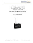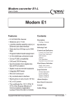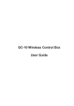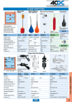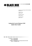
1
Remote Bitbus Master networking module
UCB-XX../RM
Remote Master modules
INTRODUCTION
The Remote Master Module UCB-xxxx/RM is a Bitbus Master module
having both BITBUS and Modbus Slave for serial communication. The
module can be used as a Remote Networking module in a RTU
network or/and as a Bitbus Master module in a standalone Bitbus
application system.
The Modbus interface can be used to programme, control and monitor
the remote unit either directly or via a hayes compatible dial-up modem
connections. The Remote Master has a BITBUS interface that
enables the master to control a number of BITBUS slave modules,
including Bitbus Slave modules with Datalogging facilities. IEC 11313 programming facilities via BCONW are used for control of the
BITBUS communication and the logical control including dial-up
procedures via modems.
The application program can be developed, down-loaded and debugged through the RS232 interface, the PC do not require a BITBUS
interface, a normal COM-port can be used. When the B-CONW
programme which can control the process is made and installed in the
Remote BITBUS master, the RS232 port can be used for monitoring
purpose directly or via modem or radio. Downloading IEC1131-3
BCONW application program to the connected Bitbus Slave modules
is also done via the Serial link on Remote Master.
VERSIONS/ORDERING CODES
Example:
UCB- 16DIO/10.P1/RM
Type
UCB
UCB
Input/Output
16 digital input /
16 digital output
None
For Remote Networking the Remote Master can be a part of a RTU
network together with the Series 4000 RTU8 modules. Logged data
in connected Bitbus Slave Datalogging modules can be transferred
via the serial RS232 port to the RTU Master PC with IOTOOL32.
16DIO/xx.P1
61MD
Power supply
External Power Supply *)
Built-in mains PS 110-240V 10
Built-in mains PS 24-48VDC 30
The Remote Master is delivered in 2 general versions; with or without
I/O. Expansion I/O modules can be added to both Remote Master
versions.
The unit is designed in a very compact 108/162 mm wide module for
DIN-rail mounting (35 mm symmetrical ). Dimensions conform to DIN
43880 (used for circuit breakers) thus insuring easy installation in
standard installation panels and boxes widely available in the electrical
industry.
Option
Remote Master/RM
*) only UCB-61MD/RM
Typical Remote Master application
Central
Monitoring
Modem
Modem
Modem
RTU8
RTU8
PSTN/Leased Line Multidrop
BITBUS
Modem
Remote
Master
Brodersen Controls A/S
40075 1.00/20.02
*
Industrivej 3
*
BITBUS slave
I/O + data logging
DK-4000 Roskilde
*
BITBUS slave I/O
Denmark
*
Tel
BITBUS slave
gateway PLC
(+45) 4674 0000
*
Fax
(+45) 4675 7336
1
Remote Bitbus Master networking module
UCB-XX../RM
CONTENT
TECHNICAL DESCRIPTION
Introduction ......................................................................... 1
Introduction text ............................................................ 1
billed af modul(s) ........................................................... 1
Typical application ........................................................ 1
Version / ordering code ......................................................... 1
Technical description ............................................................ 2
Input/output ................................................................... 2
I/O expansion ................................................................ 2
CPU capacity ................................................................ 2
Bitbus Network .............................................................. 2
Serial interface RS232 .................................................. 3
Handshake RTS/CTS ................................................... 3
Modbus protocol / I/O database ................................... 3
Configuration ......................................................................... 5
Station addressing ........................................................ 5
Code switch .................................................................. 5
Module configuration table - overview ......................... 5
Module configuration table - description ...................... 6
Application program parameteres ....................................... 7
Local control (B-CONW) .............................................. 7
I/O addressing _ structure ........................................... 7
Modem control .............................................................. 8
Data registers - details ................................................. 9
Error handling .................................................. 9
Modem ............................................................. 9
User registers ................................................. 9
Code Switch/Address selector ..................................... 9
Data registers - overview ............................................. 9
Technical data ....................................................................... 10
Interfaces .................................................................... 10
Serial interface ............................................... 10
Bitbus ............................................................. 10
Control/IEC1131 ............................................ 10
IO expansion bus .......................................... 10
Power supply .............................................................. 10
Supply versions ............................................. 10
Digital input/output ....................................................... 10
Inputs incl. circuit ........................................... 10
Outputs incl. circuit ........................................ 10
Isolation ....................................................................... 11
Indicators .................................................................... 11
General data ............................................................... 11
Current consumption .................................... 11
Isolation .......................................................... 11
Ambient temp. ................................................ 11
EMC ............................................................... 11
Climatic .......................................................... 11
Mechanical ..................................................... 11
Protection IP .................................................. 11
Mounting ........................................................ 11
Terminals ....................................................... 11
Housing .......................................................... 11
Note remarks ....................................................................... 11
Input/output
The Remote Master is available in 2 versions; one with buit-in I/O and
one without. The UCB-16DIO../RM include 16 digital inputs (1030VDC) and 16 digital outputs (PNP open collector).
All digital I/O´s are equipped with opto-couplers.
All Remote Master modules have local bus connector for adding
I/O Expansion modules.
I/O expansion
The basic I/O fit of the Remote Bitbus Master can be expanded by
attaching System expansion modules.
Remote Master with expansion modules
Expansion modules are available with the following I/O configuration:
8-32 10-30V inputs
8-32 10-30 V PNP (or NPN) open collector outputs
8 230V inputs / 8 230V outputs (potential free relay)
4-8 analogue inputs (0-10V, 4-20mA, etc.)
4 analogue outputs (0-10V, 4-20mA, etc.)
A maximum of 30 expansion modules can be connected to a Remote
Bitbus Master. The total number of I/O´s is limited to 104 analogue or
496 digital I/O´s (maximum 104 words or 31 I/O sections). A word
equals one analogue channel or 16 digital channels. Please note that
modules with more than 16 I/O´s should be considered as 2 or 3
I/O sections.
In the event that the current consumption of the expansion modules
exceeds the capability of the power supply, an additional power supply
must be inserted.
CPU capacity/performance
The Remote Bitbus Master is equipped with an 8 bit micro-controller.
The time related performance versus capacity of the Remote Master
is dependent upon the actual load on the micro controller, which
directly relates to the application and therefore the technical data
herewith cannot be considered in isolation. Where doubt exists we
recommend making a test, to evaluate the actual performance.
Bitbus Network
The BITBUS system is fully self configuring. At powering up, the
master will search for up to 31 slave nodes (numbered 2..250) on the
BITBUS, and I/O modules on the local bus on the master. When 31
nodes are found, searching is stopped. The configuration for every
valid node is then stored in EEPROM. A database check sum is
computed and saved in EEPROM, and the master starts scanning all
found Bitbus nodes. The system LED is initially ON.
If the local configuration i.e. connected Bitbus slaves is changed after
powering up, the I/O led will go off.
Appendix A ......................................................... 12
System / application notes ................................................. 12
Scanning ..................................................................... 12
Download procedure .................................................. 12
Example of application ............................................... 12
Procedure example .................................................... 12
Appendix B
.......................................................................... ?
Installation and connection guide
Brodersen Controls A/S
2
*
Industrivej 3
*
DK-4000 Roskilde
When the system is configured, all nodes registered will be scanned
cyclicly. When connection to a slave is obtained, the input data buffer
is read from the slave and placed in the master RX-buffer. The data
is checked, and if valid, the status and data is moved to the data base.
*
Denmark
*
Tel
(+45) 4674 0000
*
Fax
(+45) 4675 7336
40075 1.00/20.02
Remote Bitbus Master networking module
UCB-XX../RM
Next output data is moved from data base to the local TX buffer, and
is transmitted via BITBUS to the slave.
The RTS Leading setting defines the delay from activating the RTS
to the first character is transmitted.
The RTS Trailing setting defines the delay from the last character is
transmitted to RTS is deactivated.
Handshake RTS/CTS
RTS is inactive when receiving data, and is activated when the RM
wants to transmit data. After activating the RTS, the RM will wait for
the CTS to become active, before start transmitting. The RTS Leading
delay is still valid in this mode, and an adjustable delay from CTS is
activated to first character is then possible. However by setting the
Leading time to zero, there is no unnecessary delay from CTS to first
character ( like normal RTS / CTS function ). After activating RTS the
RM wait up to 10 sec for the CTS signal. If timeout occur ,transmission
is discarded, and the RM wait for a new request.
Serial interface
The Remote Bitbus Master RS232 interface includes a driver which
is able to handle both the Modbus protocol (RTU slave) and Brodersen
RAC commands. Hayes compatible modem control is implemented
in the Remote Bitbus Master. The standard MODBUS protocol is used
for I/O transfer, and for configuration and up/down-load of programmes, a special command set is used.
The concept and the facilities are compatible with other Serie 2000
products, enabling the user to combine products within the product
range.
The IOTOOL32Pro MODBUS driver with DLL and DDE interface can
be used directly to link the RTU through the telephone network to a
central PC for monitoring, data upload and analysis.
RTS Leading
The RTS Leading define the delay time from activating RTS to
transmitting the first character.
The RTS Leading value is configurable in the range 0..500 of 10ms
units. Ie. up to 5000 ms.
The RS232 port (9 pole sub-D) is equipped with all hardware
handshake signals (DCD, DTR, DSR, RTS, CTS, RI).
RTS Trailing
The RTS Trailing define the delay time from the last character is
transmitted to RTS is deactivated.
The RTS Trailing value is configurable in the range 0..50 of 10 ms
units. Ie. up to 500 ms.
RS232 port (9 pole sub-D)
Pin no
1
2
3
4
5
6
7
8
9
Signal
Description/Remarks
DCD
RX
TX
DTR
SG
DSR
RTS
CTS
RI
Data carrier detect (in)
Receive data (in)
Transmit data (out)
Data terminal ready (out)
Signal ground
Data set ready (in)
Request to send (out)
Clear to send (in)
Ringing indicator (in)
Note!
When setting the Leading value to a long time ( e.g. 5 sec ) it could be
difficult to changes configuration and download Bcon programs due
timeouts in the driver. It is advisable not to use longer delay than
necessary, and configure RTS Leading delay as the last part when
using long delays. If the RM is inaccessible due long delays, the
module setting could be reset to default by setting all code switches
ON.
Modbus protocol / Data base / DLL / DDE
Serial communication according to MODBUS (RTU mode) specification is used. The layout of the data base is very similar to the one
being used in BITBUS modules (first module = first register).
All I/O can be addressed as holding registers. The holding register
addressing (Multiple read/preset command type 03/16) is used for
transfer to other Series 2000/4000 products.
MODBUS holding registers (40000...) are used for the I/O transfer.
The actual I/O´s are automatically mapped into the holding registers
according to the actual I/O configuration (number and type of expansion modules).
For programme down-load, setup and log data, a transfer special
protocol is used (still using the MODBUS frame).
The Remote Bitbus Master has a selectable MODBUS address (low
level address, 1-31) used in radio or multi drop systems. For modem
operation, a logical address (station no., 0-65535) is used for identification of each Remote Bitbus Master. Using the IOTOOL32Pro toolkit each station will have its own net, thus the station number and net
number are the same.
Using IOTOOL32Pro Modbus PC driver
Series 2000/4000 products are supported by low level PC drivers for
Windows 95/98, WinNT and Win2000 plus a number of dedicated
drivers for standard SCADA packages.
The remote units can be operated by the IOTOOL32Pro Modbus
driver which includes dial-up and modem facilities.
Handshake on the Modbus port in NullModem mode
The use of RTS, CTS handshake, leading and trailing delays are user
configurable via the PC utility menu. The settings are only active in non
modem mode. In modem mode ( Dial-up ) the RTS is always on.
The handshake functions are as follows.
The driver interface directly to most Windows programmes through
DLL or DDE interface.
The data structure when using the driver is common for all Series
2000/4000 products. The DLL includes a database which is a mirror
of the process values related to a given remote unit. The values are
separated into 4 data types digital (DI/DO), analogue (AI/AO) and one
auxiliary types (YI/YO) and gateway data (ZI/ZO).
Handshake RTS Off
RTS is kept inactive ( low ) at all time. RTS Leading and Trailing values
are don’t care.
Handshake RTS On
RTS is kept active ( high ) at all time. RTS Leading and Trailing values
are don’t care.
Handshake RTS On/Off
RTS is inactive when receiving data, and become active when
transmitting data.
When using a dedicated IOTOOL32Pro driver, the user do not need
to consider the actual MODBUS protocol being used for the remote
units. For each remote station the number of I/Os is specified by type
and number. The MODBUS driver automatically imports the data
received via the MODBUS into the correct position in the data base.
For each remote station it is possible to configure the driver to perform
automatically polling of the station with a given interval. Further the
driver will accept calls initiated by the remote station.
Brodersen Controls A/S
40075 1.00/20.02
*
Industrivej 3
*
DK-4000 Roskilde
*
Denmark
*
Tel
(+45) 4674 0000
*
Fax
(+45) 4675 7336
3
Remote Bitbus Master networking module
UCB-XX../RM
The data collected by the driver is easily accessed from the application
by a specifying an unique address built-of:
To be able to interface to existing third party products the analogue
/digital I/Os can be operated (in parallel / alternatively) with specific
MODBUS I/O commands.
<data type><Network/station><node/island><module/group>[<I/O terminal>]
Using gateway to Series 2000 BITBUS system.
The protocol used for the remote slave is compatible with the protocol
used in the MODBUS gateway, UCB-61SD/MO. In case I/Os in a
BITBUS system have to use telephone lines, a remote slave/island can
therefore be integrated in the BITBUS network by using a gateway and
2 external modems. Both leased lines and dial-up lines can be used.
Up to 100 leased lines (or parallel dial-up lines) can be operated. Each
line will be served by a gateway which are linked by the BITBUS.
MODBUS
register
I/O
Data type
MODBUS
command
00001-00497
10001-10497
30001-30121
DO
DI
DI/AI/YI
Boolean/Bit
Boolean/Bit
Integer/word
01/05
02
04
It is possible to read the status of the outputs by a read command to
a given output reference.
If a register is addressed which is not represented by an I/O, correct
response is still given at the MODBUS.
Non existing inputs will be returned with the value “0”.
Non existing outputs addressed will be disregarded.
When using a gateway the data received via the MODBUS is mapped
into the BITBUS as for other gateways meaning that the data will appear
as ZIs/ZOs (4000 registers) at the BITBUS.
Example:
Remote unit
MODBUS
Holding Register
BITBUS
Master reference
Station address
Status H/L
inputs
:
inputs
40001
40002
40003
:
40100
ZIx-0/x.wi4000
ZIx-1/x.wi4001
ZIx-2/ x.wi4002
:
ZIx-99/x.wi4194
outputs
40301
ZOx-0/x.wo4000
:
:
:
outputs
40400
ZOx-99/x.wo4198
“x” is the slave address for the BITBUS gateway module.
It should be noted that if using a BITBUS gateway as counterpart the
gateway limits the data transfer to 120 words in total in each direction.
Also it should be noted that designation input/output is defined seen
from the master.
The data will be located in the same registers independent of the actual
station connected meaning that in case more remote stations use the
same gateway, the application programme must use the station no.
to designate the data.
Using third party MODBUS interface.
The inputs always starts in the first holding register with the Logical
address and the status in the two first words.
The start and the size of the area of holdings register used for inputs
and outputs must be configured using SM. The inputs always starts
at holding register 40001.
Example (default configuration):
MODBUS
I/O
MODBUS command
register
40001
40002
40003
:
40100
Logical address (integer)
Status H/L (word)*
Input (DI/AI/YI)
03
:
:
:
03
40301
:
40400
Output (DO/AO/YO)
Output (DO/AO/YO)
03/06/16
:
03/06/16
49999
Communication state
03/06/16
Input (DI/AI/YI)
* The status word indicates any error in the remote unit. The individual
flags are similar to those in other Series 2000/4000 products refer to
IOTOOL32 manual.
Brodersen Controls A/S
4
*
Industrivej 3
*
DK-4000 Roskilde
*
Denmark
*
Tel
(+45) 4674 0000
*
Fax
(+45) 4675 7336
40075 1.00/20.02
Remote Bitbus Master networking module
UCB-XX../RM
CONFIGURATION
Code switch/Address selector
The code switch at the slave module selects the address, baud rate,
etc.
Station address (net No.)
When using dial-up modems connected to the Public Switched
Telephone Network, a number of Remote units will normally enter a
central monitoring station through the same physical connection. In
order to be able to identify the Remote units, the station number is
transferred in the first input holding register. The station no. (0-65535)
is the sum of the binary value selected using code switches 1-5 and
the binary value of the logical address configured in the EEPROM
(default = 0).
Code switch
ON
ON
OFF
1 2 3 4 5 6 7 8 9 10
20 21 22 23 24
Baud rate OFF= 62.5kBPS
BITBUS ON = 375kBPS
Physical address
Modem
OFF = Modemcontrol
disabled.
ON = Modem control
enabeld.
The central monitoring station must use the station number address
to direct the received data to the correct location.
MSB
Modem
enabled
000 =
100 =
010 =
110 =
001 =
101 =
011 =
Station number address (0-65535)
=sum of code switch 1-5 and logical address
configuration word.
MSB
Modem
disabled
Switch no. 678
LSB
Baud rate
300
600
1200
2400
4800
9600
19200
LSB
The station number address/modem mode is defined as the sum of
the binary value selected using switch 1-5 and the binary value of
the logical address configured in the EEPROM (default = 0).
The EEPROM value can be changed by using IOExplorer - see
configuration section.
Setting all swtiches on and power up will reset the module to factory
setting.
Physical address 1-31 (MODBUS address)
= code switch 1-5 (logical address is ignored)
Remote Bitbus Master in Modem mode
The MODBUS address (physical address) is set to address 1
(independent of the switch) when modem control is enabled.
Please note that the PC MODBUS driver only supports station
numbers 0-1999.
Configuration table in Remote Bitbus Master
After scanning the Remote Bitbus Master with the IO Explorer, it is
possible to select the Config-folder and there configure the Remote
Master and also enter the pre-define telephone numbers. Refer to
separate description.
Remote Bitbus Master in NullModem mode (direct connected)
When set to direct connection (NullModem), the Modbus address can
be selected with the switches. All the Bitbus Slaves connected to the
Remote Bitbus Master, will be seen from the Modbus Master as
Modbus nodes. Please plan your application node addressing by
selecting unique addresses to all notes in your network (both Bitbus
Slaves and RMs).
Remote Master configuration table (note 2)
Product
Note: Multi-drop applications with more than 50 nodes in one net is not
recommended due to long communication delays.
In such application it is better to split the application into separate nets.
: UCB-XX/RM
Software version : 1.30
Field Type Description
( Min..Max )
1.
2.
3.
4.
5.
6.
7.
8.
9.
10.
11.
12.
13.
(40001..40300)
(40301..40600)
(
0..65503)
( 0..10 )
( 1..256 )
( 1..10 )
( 2..120 )
( 0..9 )
( 0..0 )
(
0..65535)
( 1..4 )
( 0..500 )
( 0..50 )
W PLC TX Dreg
W PLC RX Dreg
W Logical addr
W Retry count
W Max comm cnt
W Subs. to try
W Redial delay
T Tel. no.
T Modem init.
W User
W HandShake
W RTS Leading
W RTS Trailing
: Current Value
Unit
:
:
:
:
:
:
:
40001 Holding reg
40301 Holding reg
0
3
256
1
90 Seconds
:
:
:
:
0
3 RTS On/Off Modbus
1
of 10 msec
0
of 10 msec
Field Description
1.
2.
Brodersen Controls A/S
40075 1.00/20.02
*
Industrivej 3
*
DK-4000 Roskilde
*
TX defines the first Modbus holding register to be used for
data, transferred from the Remote Bitbus Master to the PC
Modbus Master.
RX defines the first Modbus holding registers to be used for
data transferred from the PC Modbus master to the Remote
Master.
Denmark
*
Tel
(+45) 4674 0000
*
Fax
(+45) 4675 7336
5
Remote Bitbus Master networking module
UCB-XX../RM
3.
4.
5.
6.
7.
8.
9.
10.
11.
12.
13.
The Logical address for a given Remote Master.
The station address is defined as logical address + code switch
(1-5) address.
The station address corresponds to netnumber on the PC.
Defines the number of retries which should be made to the
same telephone number before giving up or continuing to the
next number, if the call is not successful.
Number of successful communication requests before automatically hanging-up. The value 256 will disable auto-hang-up. The
internal register BM5 contains the actual communication counter. It is recommended that the controlling station (PC) should
terminate the modem connection.
Defines whether alternative telephone numbers should be tried.
E.g. if 3 is selected the module, in increasing order, tries the first
3 pre-stored numbers. As soon as a proper connection is
established following numbers will not be tried.
Defines the delay from an unsuccessful attempt to dial to a new
attempt to establish connection.
Up to 10 pre-stored telephone numbers, each number can
be up to 20 digits,
Dial digits 0-9, #, *, A, B, C, D can be entered to select a phone
number. A number of control characters can also be entered:
T
Tone dial
P
Pulse dial
,
Delay/pause (2 seconds).
W
Wait for dial tone (5 seconds).
Some special functions may be selected, refer to modem
user manual for further information.
Modem initialisation string. Experience shows that many manufacturers of modems make minor additions or variations
from the standard, therefore reference must be made to the user
manual for the actual modem to be sure that correct initialisation
of the modem is made. The following default string is used:
AT E0 V0 &C1 S0=1
The string can be changed by entering appropriate ASCII
characters. Any data compression or error correction
MUST be switched OFF.
User defined parameter which can be used for set-points or
other programme controls in the B-CONW application programme. The value entered in field 10 is copied to registers
bm6/bm7 (wm6) in the B-CONW programme. The value is
entered as an integer (0-65535), however in practice this
could be separated into 16 individual bits or 2 bytes, each
having a specific function in the application programme.
Primary serial port handshake . Select RTS, CTS function.
Defines the delay from the Remote Bitbus Master is activating RTS, to transmission of first character.
Defines the delay from the Remote Bitbus Master is transmitting last character to deactivating RTS.
Brodersen Controls A/S
6
*
Industrivej 3
*
DK-4000 Roskilde
*
Denmark
*
Tel
(+45) 4674 0000
*
Fax
(+45) 4675 7336
40075 1.00/20.02
Remote Bitbus Master networking module
UCB-XX../RM
I/O addressing (B-CONW)
The address of the I/O in the Remote Bitbus Master has the same
structure as other Series 2000/4000 products. The I/O´s are separated
into 4 data types; digital (DI/DO), analogue (AI/AO) and 2 auxiliary
types (ZI/ZO and YI/YO). In the Remote Bitbus Master the YI/YO is
used for transfer of derived values or set-points, to and from the local
CPU, to the central PC.
The RTU8 handles bits (Boleans) and Integers (8/16 bit). Analogue
values have to be handled as integers; floating point operation (Reals)
is not supported.
The PC software tools use words (16 bits) as a reference for
addressing the I/O, but as the Remote Bitbus Master is equipped with
an 8 bit controller, the addressing uses bytes (8 bits) as a reference.
The inputs and outputs are numbered in the order they appear
physically (left to right). Please note that input/output and analogue/
digital are numbered separately.
APPLICATION PROGRAMMING PARAMETERS
Local control
The Remote Bitbus Master modules can perform central control of
a BITBUS network, e.g. a sub-network covering the actual site to
be controlled or monitored.
The Remote Bitbus Master modules are directly compatible with
other Series 2000/4000 units enabling the user to make any type of
combination between intelligent and non intelligent BITBUS units.
The Remote Bitbus Master includes B-CONW programming facilities i.e. it can be programmed using IEC 1131-3 Instruction list
programming language.
The processing and data handling to be performed is configured by
use of a PC having the B-CONW programming tool installed. The BCONW programming tool includes an integrated editor, compiler,
debugger and down-load facility for developing application programmes and down-loading them via the RS232 to the actual
Remote Master module.
Database interface / Register layout
Program development
Digital
Analog
Reserved
AO
ZO
RS232
LD
ST
LD
AND
STN
LD
ST
12.0
O 0.5
I 1.0
I 1.2
M 0.6
WI 2
WM 16
DO
Download
through
RS232 to
EEPROM
WO 0-1999
YO
WO 2000-3999 WO 4000-5999 WO 6000-7999
Remote BITBUS Master
B-CON
Application program
Integrated editor /
debugger / compiler
The application programmes are written by use of Instruction Lists
according to the IEC 1131 programming language.
WI 0-1999
DI
Examples of instructions in the IEC 1131 language:
LD
load (read) value e.g.: input or internal register
ST
store (write) value e.g.: output or internal register
AND logical and e.g.: 2 inputs
ADD add 2 values
MUL multiply 2 values
R
reset e.g.: an output
GT
greater than, compare 2 values
Digital
Address
status
The B-CONW application programme resides in the master module
controlling the entire intercommunication in the BITBUS network
and performing simple logical operating. Also the B-CONW programme can include limits or conditions for making a call via the
telephone network to a central monitoring station.
The compiled instructions are down-loaded to an EEPROM in the
actual slave or master module. A simple load (LD) or store (ST)
instruction require only about 10 bytes of memory.
WI 2000-3999 WI 4000-5999 WI 6000-7999
AI
ZI
Analog
Reserved
YI
YI
Read
MODBUS master
Write
In general software tools, register layout, I/O addressing and
principles are as in other Series 2000/4000 with only minor additions.
The IOTOOL32Pro is a total software package with nessesary
drivers and programming tools.
YO
A number of internal registers are dedicated to control the modem
(dial-up etc.).
Brodersen Controls A/S
40075 1.00/20.02
*
Industrivej 3
*
DK-4000 Roskilde
*
Denmark
*
Tel
(+45) 4674 0000
*
Fax
(+45) 4675 7336
7
Remote Bitbus Master networking module
UCB-XX../RM
Example of an island
UCR-32DI
UCL-08DO
UCL-08AI
UCL-04AO
UCL-16DIO
WI4
WI0
8DI
8DI
2 3 4 5 6 7 C
In
C 8 9 10 11 12 13 14 15 C
In
B
System
A
BRODERSEN
0 1 2 3 4 5 6
7
BRODERSEN
In
C 8 9 10 11 12 13 14 15 C
BRODERSEN
UCL-08 DO.R1
A
0
1
0
2
1
3
2
A
4
3
5
4
6
5
0
7
6
7
1
0
2
1
3
2
4
3
4DO
BI3
4DO
BO0
WO0
WI2
C I O V
2AO
2
3
0 1 2 3 4 5 6 7
8 9 10 11 12 13 14 15
2
3
Out
C 0 1 2 3 4 5 6 7
Out
C 8 9 10 11 12 13 14 15
C I O V
C I O V
8DO
2AO
8DO
BO2
BO3
WO2
The application related modem control (related to the process values)
and conditions for making dial-up etc., are handled by the B-CONW
application programme in the Remote Bitbus Master. Modem control
is performed through 4 internal registers (BM2 to BM5).
The calls are made to pre-stored numbers. By specifying alternative
numbers if a connection is not made to the primary number, then the
secondary numbers will be called in turn, until a successful connection
has been made. The number of retries is limited to one cycle, i.e. after
the pre-stored numbers and the number of retries per number have
been called without success, the Remote Bitbus Master will suspend
the dial-up. The maximum allowed number of dial-up attempts will be
the number of “pre-stored numbers to try” multiplied by “Retry count”.
If the Remote Bitbus Master is unable to make a connection, an error
indication is given to the application, (m4.7 is set). The error flag is reset
when the Remote Bitbus Master receives an incoming call (carrier
detected) or when the value in the dial register (bm2) is activated
(changed from 0 to 1) in order to force a new dial-up.
Aux. input (YI), e.g. setpoint transfered via the MODBUS from a
central station:
Bit input:
i6000.0, i6000.1....i6000.7, i6001.0, i6002.0..
i6000.0 is the first input in the first byte/word.
i6001.0 is the first input in byte 1.
Byte input:
bi6000, bi6001, bi6002, b600i3…..
bi6000 loads the first 8 digital inputs (input 0-7).
Word input:
wi6000, wi6002, wi6004, wi6006………
wi6000 loads the first 16 digital inputs (input 0-15).
8
1
1
Modem control (Dial-up)
Both the Remote Bitbus Master and the central monitoring station can
initiate a dial-up to each other. The central monitoring station may dial
the Remote Bitbus Master at time intervals, if the Remote Bitbus Master
detects a situation, which is pre-defined to be a call situation, it can
immediately dial-up the central monitoring station and report the actual
condition.
Analogue output (AO):
Output (word): wo2000, wo2002……., wo2014, wo2016………
wo2000 sets the first analogue output (channel
0).
wo2014 sets the analogue output channel 3 at the
second AO module.
DK-4000 Roskilde
0
0
C I O V
bo6000, bo6001, bo6002, bo6003…..
bo6000 sets the integer of the first 8 outputs (0-255).
Word output: wo6000, wo6002, wo6004, wo6006………
wo6000 sets the integer of the first 16 outputs (065535).
Analogue input (AI):
Input (word): wi2000, wi2002……., wi2014, wi2016………
wi2000 loads the integer (0-4095) of the first
analogue input (channel 0).
wi2014 loads the integer (0-4095) of the analogue
input channel 7.
*
C
D
Byte output:
Digital Output (DO):
Bit output:
o0.0, o0.1…..o0.7, o1.0…o1.7, o2.0……
o0.0 sets the first digital output (output 0).
o1.0 sets output number 8 (first output in byte 1).
Byte output: bo0, bo1, bo2, bo3…..
bo0 sets the integer of the first 8 outputs (0-255).
Word output: wo0, wo2, wo4, wo6………
wo0 sets the integer of the first 16 outputs (0-65535).
Industrivej 3
7
I/O
UCB-16 DIO.P1
C
Aux. output (YO), e.g. result to be transfered via the MODBUS to a
monitoring station
Bit output: o6000.0,o6000.1..o6000.7,o6001.0..o6001.7,o6002.0..
o6000.0 sets the first output (output 0).
o6001.0 sets output number 8 (first output in byte 1)
bi0, bi1, bi2, bi3…..
bi0 loads the first 8 digital inputs (input 0-7).
wi0, wi2, wi4, wi6………
wi0 loads the first 16 digital inputs (input 0-15).
*
7
6
4AI
Digital input (DI):
Bit input:
i0.0, i0.1…..i0.7, i1.0…i1.7, i2.0……
i0.0 loads the first digital input (input 0).
i1.0 loads digital input number 8 (first input in
byte 1).
Brodersen Controls A/S
6
5
C
4AI
In the B-CONW programming language the following address and
syntax are used for the I/O:
Word input
5
4
C
WI2008
WI2010
WI2012
WI2014
8DI
BI2
B
System
BRODERSEN
A
WI2000
WI2002
WI2004
WI2006
8DI
8 9 10 11 12 13 14 15
UCL-04 AO
BRODERSEN
UCL-08 AI.D1
C
Byte input:
Out
C 8 9 10 11 12 13 14 15 C
In
A
8 9 10 11 12 13 14 15
In
2 3 4 5 6 7 C
B-CON
address
In
Out
0 1 2 3 4 5 6 7
D
C
C 0 1
In
Out
8DI
5 6 7 C
I/O
UCB-20 IO/PS
UCB-61SD/XX/PS
UCB-32DI.D1
12V
In
C 0 1 2 3 4
In
8 9 10 11 12 13 14 15
3 4 5 6 7
BI5
8DI
WO2006
0 1 2
BI4
I4.0
I1.7
WO2004
C 0 1
BI1
WO2002
L N
110-240V~
BI0
WO2000
B-CON
address I0.0
Low level modem control is performed by the firmware which includes
a modem initialisation routine, which is executed at power-up and
every time a dial-up is initiated.
The following Hayes commands are used to control the external
modem:
+++
Enter command mode
ATZ Reset modem
ATE0 Echo off
ATD Dial up
ATH Hang up
V0
Displays digital format
*
Denmark
*
Tel
(+45) 4674 0000
*
Fax
(+45) 4675 7336
40075 1.00/20.02
Remote Bitbus Master networking module
UCB-XX../RM
The string ATZ ATE0 V0 is used for modem initialisation by the Remote
Bitbus Master. Experience shows that many manufacturer of modems make minor additions or variations from the standard. Therefore
reference must be made to the user manual for the actual modem,
to be sure that correct initialisation of the modem is made. The second
part of the initialisation string can be configured to fit the actual modem
using the IO Explorer, which is part of the tool-kit in IOTOOL32Pro.
telephone numbers are defined in the configuration menu, using the
IOTOOL32 software. The telephone number register (bm3) can be
used either to force the use of a given pre-defined number, by writing
the number into the register - or it can be used to read the actual number
currently being dialled. The automatic dial procedure writes the actual
number into the register, allowing the B-CONW application programme to monitor the number being dialled and control it accordingly.
Default string: AT E0 V0 &C1 S0=1
CTS, DSR, RI and DCD (input) are the handshake signals (bit inputs)
from the modem, which may be used in the application programme to
control the modem.
&C1
S0=1
Track presence of data carrier (DCD).
Auto answer.
The communication state (input) can be used to monitor when a
transfer of I/O data has successfully taken place. The communication
state is controlled by MODBUS Holding register 49999. The PC driver
(MODBUS master) writes to the register when the PC has received
all the registers defined.
Some modems store the setup in non-volatile memory, in which case
the setup can be made directly in the modem and the initialisation string
can be omitted. Please note that if a modem has data compression
capabilities, this facility must be switched off.
The communication counter (input) can be used to monitor if the
transfer of data is successful. In every read or write cycle on the
MODBUS, the counter is incremented. The Remote Bitbus Master
requires at least two messages (Read and Write) to update. For third
party equipment/software several messages might be required to
update a remote unit depending on the actual MODBUS commands
being used. In such cases, data for the actual protocol driver must be
consulted or the value must be set to a suitably high figure.
Data registers - details
Error/indicator/alert (inputs)
Run time errors and corresponding indicators are monitored/controlled using BM0 and BM1. Details in B-CONW manual.
Register
BM0
BM1 m1.0
m1.1
Description
Runtime error/overflow
System indicator
System indicator
When the line connection is terminated, the communication state and
the communication counter are returned to 0.
User registers
BM6 and BM7 (WM6) are directly derived from the “User” field in the
configuration menu. By using IOExplorer, it is possible to enter
parameters into an application programme, e.g. a set-point without
having to re-compile.
Modem control registers
The modem is controlled from 4 internal registers (M-registers).
Register
Description
Register
BM6
BM7
BM2
Command register (output)
0=No action, st. by
1=Dial no. selected by bm3
2=Hang up
BM3
Telephone (selection) no. (0-9)
BM4
m4.0
m4.1
m4.2
m4.3
m4.4-m4.5
CTS, Clear to send (input)
DSR, Data set ready (input)
RI, ringing indicator (input)
DCD, Data carrier detect (input)
Communication state (read only)
m4.6
m4.7
BM5
54
00
State
Idle
01
Active
10
All updated
Description
User register high byte
User register low byte
Code switch (inputs)
The setting of the code switches are copied to internal registers (BM8/
BM9) for monitoring purposes. Please note that the code switches are
used by the firmware, therefore they cannot be used independently.
Register
BM8
m8.0
m8.1
m8.2
m8.3
m8.4
m8.5
m8.6
m8.7
BM9
m9.0
m9.1
Remark
No communication
(comcounter =0)
Communication
(comcounter > 1)
Set when all inputs
has been read once
Not used
Dial request suspended (1"=Error)
Description
Code
Code
Code
Code
Code
Code
Code
Code
switch
switch
switch
switch
switch
switch
switch
switch
1
2
3
4
5
6
7
8
Code switch 9
Code switch 10
Address
Address
Address
Address
Address
Baud rate
Baud rate
Baud rate
Modem OFF/ON
Bitbus speed
Communication counter
The command register (output) is used to initiate and terminate a call.
The call is made to the pre-stored number selected in the telephone
register, see above.
The telephone number (output) is selected from up to 10 pre-stored
telephone numbers to decide which number to dial. The pre-stored
Brodersen Controls A/S
40075 1.00/20.02
*
Industrivej 3
*
DK-4000 Roskilde
*
Denmark
*
Tel
(+45) 4674 0000
*
Fax
(+45) 4675 7336
9
Remote Bitbus Master networking module
UCB-XX../RM
Data registers - overview
BM/reg.
BM0
BM1
BM2
BM3
BM4
BM5
BM6
BM7
BM8
BM9
Delay:
375kBPS:
Description
error/overflow
m1.0
m1.1
2
n
2
n
62.5kBPS:
system indicator
system indicator
Baud rate/cable
length, etc.:
command register 1=dial, 2=hang up
telephone no.
m4.0-m4.3
handshake inputs
m4.4-4.5
Com state
m4.7
Dial time out (error)
communication counter
User info (derived from USER field in the IOExplorer
config. menu)
m8.0
switch1
Address
m8.1
switch2
Address
m8.2
switch3
Address
m8.3
switch4
Address
m8.4
switch5
Address
m8.5
switch6
Baud rate
m8.6
switch7
Baud rate
m8.7
switch8
Baud rate
m9.0
switch9
Modem on/off
m9.1
switch10
Bitbus speed
islands:
islands:
islands:
islands:
Typical
Typical
Typical
Typical
40ms.
n x 50ms.
50ms.
n x 25 ms.
Refer to installation guidelines.
CONTROL IEC1131-1
IEC 1131-3 (B-CONW)
Program memory (Flash):
Memory usage per
instruction line:
Typical maximum
program size:
Scan interval:
Internal registers (BM):
23 Kbytes (note 19).
6-24 bytes.
1500 instruction lines.
50-250 ms (note 1).
1024.
I/O expansion bus
Capacity:
Connector:
Signal level:
Protocol:
Local bus cable length:
max. 31 I/O sections (up to 30 expan
sion modules).
max. 104 analogue or 496 digital I/O
(104 words total).
RJ45 Modular jack, 8/10 pole.
5V (CMOS).
Synchronous data (shift register type).
Max. 1 m between 2 modules.
Max. 5 m totally.
TECHNICAL DATA
INTERFACE
POWER SUPPLY
Serial interface RS232 (ModbusRTU):
Signal level:
RS232C/v.24.
Connector:
9 pole sub-D, male.
Hardware handshake:
DCD, DTR, DSR, RTS, CTS, RI
External power supply:
System supply:
Modem control
Dial-up (modem)
Protocol:
Error Check:
Outputs:
Output current, total
Modbus slave (RTU mode).
CRC (16).
BITBUS interface:
Signal level:
Isolation (to other
electronics):
Protocol:
Output 12V
expansion (local bus)
Output 12V
external output
RS485 multidrop.
500V AC.
Intel standard / Serie 2000 compatible.
Capacity:
Isolation:
Input/mains (primary) to
electronics (secondary)
Max. 1 master + 31 slaves.
Max. 496 digital I/O signals or
max. 196 analog I/O signals per
island.
Scantime:
375kBPS:
62.5kBPS:
10
Mains supply:
Supply voltage nominal
Supply voltage absolute
maximum input range
Mains frequency
Power consumption
300, 600, 1200, 2400, 4800, 9600,
19200
8 bit (binary), 1 start bit.
No parity, 1 stop bit.
Format (default):
Brodersen Controls A/S
Built-in power supply:
Hayes compatible.
DTMF or pulse dialling to pre-stored
telephone numbers.
Up to 10 pre-stored numbers.
Each number can be up to 20 digits.
Baud Rate:
UCS-53/54
10
110-240V AC/DC
30
24-48V DC
100-265V
40-60 Hz
Max 18W
20-65V
DC only
Max 14W
1.1 A
0.9 A
12V +/- 0.5V
(note 3,4)
12V +/- 1.5V
max. 400mA
(note 3,4,5)
12V +/- 0.5V
(note3,4)
12V +/- 0.5V
max. 400mA
(note 3,4,5)
3,75 kV
1500V AC
Approx. 5 ms per island/slave.
Approx. 15ms per island.
*
Industrivej 3
*
DK-4000 Roskilde
*
Denmark
*
Tel
(+45) 4674 0000
*
Fax
(+45) 4675 7336
40075 1.00/20.02
Remote Bitbus Master networking module
UCB-XX../RM
DIGITAL INPUT/OUTPUT(UCB-16DIO../RM only)
Isolation:
Inputs:
Input voltage activated:
10-30V DC (note 6,7).
Input voltage deactivated: Max. 3V DC.
Input current: 12V DC: Typical 3mA.
24V DC: Typical 6mA.
Input delay:
Typical 1ms.
IEC class II, 3,75 kV.
(mains supply versions)
Safety earth required.
Ambient temperature:
EMC:
-10 - +55°C.
EN 50081-1/EN50082-2.
Climatic:
Dry heat:
Input circuit:
IEC 68-2-2, Test Bd, Temp. +55°C,
Duration 8h.
IEC 68-2-1, Test Ad, Temp. -10°C,
Duration 8h.
IEC 68-2-3, Test Ca, Temp. 40°C, RH
95%, Duration 8h.
Cold:
Damp heat:
Mechanical:
Vibration:
IEC 68-2-6, Test Fc (sinusoidal), Freq.
10-150Hz, Amp.
4g, 5 sweeps in 3 orthogonal axes.
IEC 68-2-27 (half sine), Acc. 15g, Pulse
time 11msec., 3 x 6 shocks.
Shock:
Outputs:
External voltage:
10 - 30V DC (note 6,7).
Output voltage drop:
Max. 1.5V (output activated).
Output current:
Max. 0.5A.
Output peak current:
Max. 5A in 1 second (note 6).
Output leakage current (off): Max. 0.5mA.
Output delay:
Max. 1ms.
Protection:
IP20.
Mounting:
35 mm DIN-rail, EN50022.
Terminals:
Max. 1.5 mm2 wire.
Housing:
Anodized aluminium with plastic ends.
According to DIN 43880.
Dimensions:
HxWxD:
80(+connectors)x108/162x62 mm.
Output circuit:
NOTES/REMARKS
1) The scan interval can not be selected by the user, it is the capacity of
the micro-controller that limit the minimum scan time. The time related
performance versus capacity for the RTU is a result of the actual CPU
load. The technical data related hereto, must be considered in total.
2) Setup can be configured using the IOExplorer.
3) The sum of current consumed from the 12V rail, i.e. internal
consumption, consumption from the external screw terminals and
by expansion modules at the local bus, must never exceed the
maximum total output current.
4) The 12V external supply is not isolated from the circuit supplying the
electronics. It is therefore recommended to use an external source
for the I/O if the I/O signals are influenced by electrical noise, e.g.
from long cables or inductive load.
Isolation
(input or output to electronics,
input to output):
1kV AC.
Indicators (UCB-16DIO../RM only):
Digital input:
One for each digital input (red) indicating active input.
Digital output:
One for each digital output (yellow)
indicating active output.
System:
Indicating RM OK (green)
I/O:
Indicating I/O and local bus OK (green)
Rxd/Txd:
Indicating serial communication on
RS232 line.
5) The external output is short circuit protected and overload protected.
The maximum current is limited at high ambient temperature.
The maximum load current should be de-rated approximately 1%
per °C above 25°C.
6) Input signals exceeding the maximum values MAY CAUSE
PERMANENT DAMAGE to the module.
7) The polarity at the input must be positive. The common terminal
must be connected to the negative.
GENERAL
General:
Firmware version 1.30 and later is covered by this data sheet.
Current consumption (12V):
UCB-16DIO../RM:
max. 175 mA.
UCB-61MD../RM:
max. 210 mA.
Brodersen Controls A/S
40075 1.00/20.02
*
Industrivej 3
*
DK-4000 Roskilde
*
Denmark
*
Tel
(+45) 4674 0000
*
Fax
(+45) 4675 7336
11
Remote Bitbus Master networking module
UCB-XX../RM
Procedure example:
All hardware is wired up as required, and power supply is applied.
APPENDIX A
System / Application Notes
Pre-scanning the system:
Start IOTOOL32Pro. Choose new project.
Choose New (NET) – delete all other NETs not used.
Select the highest node number to scan and press “scan” (and
await scanning procedure to finish )
Scanning and application program download procedure
After system design and hardware implementation of the modules, the
system can be scanned be the IOTOOL32Pro drivers for automatically
building up a project. After the drivers has detected the network you
are able to download the B-CONW application programs to the
relevant modules. This procedure can seem complicated but when
you are following the procedure below you will understand the flow.
Download B-CONW application programs to the Bitbus Slaves in the
first sub-net:
Open the B-CONW program for the actual slave (e.g. Node 11).
In the option/communication program menu you set the device
to Slave and define the node address.
Compile and download the program to the actual slave. After
download start the program (system LED on module = on)
Reset the Slave by highlighting it in IOExplorer and right-click the
mouse (optional).
Repeat these three points for all the Bitbus Slaves in the sub-net
When your hardware is connected you start IOTOOL32Pro on your
PC. Choose new project. The Scan box appear, you must enter the
highest node no to be scanned and select ”scan”. IOTOOL32 will scan
the network and detect all modules connected. Based on this scanning
it create the project with all the scanning data, like node no., node types
etc. The I/Os of the system is not yet all defined, as your application
program also has influence on the number of I/O, which are defined.
Download B-CON application program to the Remote Bitbus Master:
Make a Auto Config (in drop down menu >Option<,
>Communications and program< you set the device type to
Master and choose OK, and start the "auto config"). The auto
config scan the modules for physical connected net.
Open the B-CONW program for the actual Remote Bitbus Master
(e.g. Node 10).
In the option/communication program menu you set the device
to Master and define the node address.
Compile and download the program to the actual Master. After
download start the program (system LED on module = on).
Reset the Remote Bitbus Master by highlighting it in IOExplorer
and right-click the mouse (optional).
Repeat for all the Bitbus Masters in the net.
The network do now have two Master station levels, the Remote
Bitbus Masters and the PC which is the Master on the serial connection
(Modbus Master). In order to configure the system you have to start
backwards; configure the slaves in the Bitbus sub-network and then
the Master in the Modbus sub-network. This way are all the subnetwork nodes configured and finally you can rescan the whole
system from the main Master (PC) and your system is configured.
Application example:
PC with LL modems connected via LL to 2 Master networks with each
2 Slaves attached.
Programming
After system design and implemetation of the modules, the system
can be scanned and application programs downloaded after the
procedure described in this appendix.
Rescanning the whole network
After programming all Masters and Slaves make sure that
programs are running in all modules, and all modules have been
reset.
Select Rescan the Net in IOExplorer and the driver rescan your
application and built-up the final database.
M20= RM Modbus address = 20
Any errors detected after rescan can be read in the nodes status
registers (ST). A description of the codes you find by holding your
mouse steady on the register and IOTOOL32 will shortly show
the failure description. Also the IOTOOL32 manual you find on
the IOTOOL32Pro CD will explain the error codes.
PC
Modem
Remote
Master
BITBUS slave I/O
Modem
M10
S11
Remote
Master
S12
S13
BITBUS slave I/O
Modem
M20
S21
S22
S23
S21= Slave Modbus (Bitbus) address = 21
Brodersen Controls A/S
12
*
Industrivej 3
*
DK-4000 Roskilde
*
Denmark
*
Tel
(+45) 4674 0000
*
Fax
(+45) 4675 7336
40075 1.00/20.02
Remote Bitbus Master networking module
UCB-XX../RM
Brodersen Controls A/S
40075 1.00/20.02
*
Industrivej 3
*
DK-4000 Roskilde
*
Denmark
*
Tel
(+45) 4674 0000
*
Fax
(+45) 4675 7336
13