1
HIGH INTERCEPT
POINT FM BROADCAST
AMPLIFIER
Ramsey Electronics Model No.
FMBA1
Antenna mounted amplifier does its job BEFORE the line loss !
•
Virtually overload proof.
•
Ideal preamp for use near cities or strong local stations.
•
Mast mount for best signal to noise ratio and performance.
•
Also works great for low power FM transmitters.
•
Put your power at the antenna, not in the feedline.
•
Very well filtered with 5 sections of low pass filtering for excellent
harmonic performance.
•
Operates on 15 Volts DC.
•
Clear, concise instructions guide you step-by-step to a finished
product that works FIRST time.
FMBA-1 • 1
PARTIAL LIST OF AVAILABLE KITS
RAMSEY TRANSMITTER KITS
• FM25B FM Stereo Transmitter
• AM1 AM Transmitter
• TV6 Television Transmitter
• FM100B Professional FM Stereo
Transmitter
RAMSEY RECEIVER KITS
• FR1 FM Broadcast Receiver
• AR1 Aircraft Band Receiver
• SR2 Shortwave Receiver
• AA7 Active Antenna
• SC1 Shortwave Converter
RAMSEY HOBBY KITS
• SG7 Personal Speed Radar
• SS70A Speech Scrambler
• MX5, MX-10 Mixers
• MD3 Microwave Motion Detector
• PH15 Peak hold Meter
• TFM3 Tri-Field Meter
• STC1 Stereo Transmitter Companion
RAMSEY AMATEUR RADIO KITS
• DDF1 Doppler Direction Finder
• HR Series HF All Mode Receivers
• QRP Series HF CW Transmitters
• CPO3 Code Practice Oscillator
• QRP Power Amplifiers
RAMSEY MINI-KITS
Many other kits are available for hobby, school, scouts and just plain FUN. New
kits are always under development. Write or call for our free Ramsey catalog.
Ramsey Electronics publication No. MFMBA1 Rev 1.0
First printing: October 1999
COPYRIGHT 1996 by Ramsey Electronics, Inc. 590 Fishers Station Drive, Victor, New York
14564. All rights reserved. No portion of this publication may be copied or duplicated without the
written permission of Ramsey Electronics, Inc. Printed in the United States of America.
FMBA-1 • 2
Ramsey Publication No. MFMBA1
Price $5.00
KIT ASSEMBLY
AND INSTRUCTION MANUAL FOR
HIGH INTERCEPT POINT
FM BROADCAST
AMPLIFIER KIT
TABLE OF CONTENTS
Introduction............................................. 4
Circuit Description .................................. 4
Parts Layout Diagram ............................ 5
FMBA1 Parts List ................................... 6
Assembly Procedure .............................. 8
Schematic Diagram.............................. 10
Initial Testing and Operation ................ 16
Troubleshooting ................................... 18
Warranty............................................... 19
RAMSEY ELECTRONICS, INC.
590 Fishers Station Drive
Victor, New York 14564
Phone (585) 924-4560
Fax (585) 924-4555
www.ramseykits.com
FMBA-1 • 3
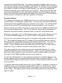
INTRODUCTION
Thank you for purchasing the FMBA1 FM Broadcast Amplifier. The FMBA1
can be used as a state of the art amplifier for almost any low power
transmitter or you can set the FMBA1 up as an excellent receive preamp.
With 5 sections of low pass filtering, your signal will come in crystal clear
over all of the noise and interference. And with an incredible gain of up to
38.5dB (7079 times the input power) at 100 Mhz, you will notice a big
difference in the signal distance and clarity. A gain of 38.5dB means that only
125 micro watts will get you 1 watt of crystal clear power!
You’ll notice that the PC board included with your kit contains plating on both
sides of the board. This topside ground “plane” is necessary to create the
proper RF impedance in the traces run on the bottom side of the board. We
have also used the latest in trouble free amplifiers, the MAV3 IC, to provide
crystal clear linear amplification.
NOTE TO NEWCOMERS: If you are a first time kit builder, you may find this
manual easier to understand than you may have expected. Each part in the
kit is checked off as you go, while a detailed description of each part is given.
If you are to follow each step in the manual in order, and practice good
soldering and kit building skills, the kit is next to fail-safe.
FMBA1 CIRCUIT DESCRIPTION
The components on the larger P14FMBA board are used to supply the
voltage to run the smaller amplifier/preamp board. The DC supplied to the
control box is sent up the coax to the amplifier board. This DC is supplied to
VR1 which then provides a regulated 12 VDC for the rest of the circuit.
The main components of the circuit are the MAV3 RF amplifier and Q2, an
MRF581 power transistor. The MAV3 is a state of the art amplifier specially
designed to work in a wide range of radio frequencies. The MAV3 amplifies
the signal, but does not have the power output capabilities to push out the
kind of high power we desire. For this reason, Q2 is placed in the circuit. Q2
amplifies the signal a bit more, and is capable of generating a large amount
of power out of the circuit.
D1 and D2 limit the input to U1 to 0.7 volts, to keep the amplifier from being
overdriven and damaged. L1, L2, C3, 4 and 5 form a lowpass filter that
reduces unwanted signals entering U1. U1 then amplifies the signal and
couples it through C6 to Q2. Q1 and its associated components provide the
proper bias for Q2. After being amplified by Q2, the signal passes through
another stage of filtering, to eliminate harmonics from the output signal. This
filtering allows the FMBA1 to produce clean, undistorted RF when used with
a transmitter or to “clean up” the input to your receiver when used as a
preamp.
FMBA-1 • 4
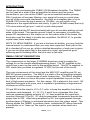
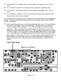
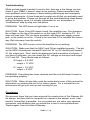
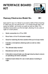
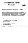
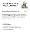
FMBA1 PARTS LAYOUT DIAGRAM
FMBA-1 • 5
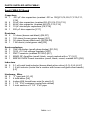
PARTS SUPPLIED WITH FMBA1
Small FMBA PC Board
Capacitors
7 .001 µF disc capacitors (marked .001 or 102)[C1,C5,C6,C7,C10,C11,
C16]
4 39 pF disc capacitors (marked 39) [C2,C4,C12,C15]
3 68 pF disc capacitor (marked 68) [C3,C13,C14]
2 10 µF electrolytic capacitors [C8,C18]
1 220 µF disc capacitor [C17]
Resistors
2 12 ohms (brown-red-black) [R6,R7]
1 150 ohms (brown-green-brown) [R1]
3 1K ohms (brown-black-red) [R2,R4,R5]
1 7.5K ohms (violet-green-red) [R3]
Semiconductors
2 1N4148 diodes (small glass diodes) [D1,D2]
1 7812 +12 Volt voltage regulator [VR1]
1 PNP Transistor (marked 221334) [Q1]
1 MAR3 RF Amplifier (small, black, round marked with a “3”) [U1]
1 MRF581 NPN Power transistor (small, black, round, marked 581) [Q2]
Inductors
5 0.1 µH axial lead inductor (brown-black-silver-silver) [L1,L2,L5,L6,L7]
1 1.2 µH inductor (looks like a resistor with brown-red-gold-silver bands)
[L3]
Hardware, Misc.
2 “F” type jack [J1,J2]
1 6 hole balun [L4]
4 Inches #28 tinned buss wire [to wind L4]
2 1 1/2 “ PVC endcaps (center hole drilled)
1 3 inch section of 1 1/2 “ PVC pipe
FMBA-1 • 6
FMBA PC Board
Capacitors
1
1
.001 µF disc capacitors (marked .001 or 102) [C1]
1000 µF electrolytic capacitor [C2]
Resistors
1 1K ohms (brown-black-red) [R1]
Inductors
2 1.2 µH inductor (looks like a resistor with brown-red-gold-silver bands)
[L1, one inductor to be installed for either preamp or amplifier mode]
Semiconductors
1 Red LED [D1]
Hardware, Misc.
1 DPDT pushbutton switch [S1]
1 2.1 mm center pin type DC power jack [J3]
1 RCA-style jacks [J1]
1 “F” type jack [J2]
Required, not supplied
12 Volt DC power transformer
Case and Knob Parts
Top Cover
Bottom Base Tray
4 - Short Phillips Head Screws
2 - Long Phillips Screws
Front and Rear Plastic Panels
Front and Rear Labels
4 - Rubber Feet
Appropriate Knobs for Kit
Required Tools
Pen or Pencil
Sharp hobby knife or hand held paper punch
Small Phillips Head Screwdriver
FMBA-1 • 7
RAMSEY "LEARN-AS-YOU-BUILD" ASSEMBLY STRATEGY
As you can see in examining the circuit board and components, there is a bit
more to this kit than just soldering a few parts. So that you don't spend extra
time "troubleshooting" instead of enjoying your new kit, we strongly
recommend that you follow the assembly strategy and step-by-step
procedures we provide.
Our strategy in installing parts on our PC board is to install the larger and
more obvious parts such as the connectors and controls. These parts will then
act as "landmarks" so that each additional device installed is seen in
relationship to them, or to others previously installed.
Since the FMBA1 runs at very high frequencies, it is extremely important that
you follow the instructions provided. Incorrectly installed components,
excessively long component leads, and bad solder joints may mean that your
kit won’t work. For reasons like this it is advisable to follow the step-by-step
instructions in the manual and not jump ahead.
Be sure to read through all of the steps, and check the boxes as you go along
to be sure that you didn't miss any important steps. Before you switch on the
power in a hurry to see results, check all transistors, the MAV3 amplifier, D1
and C2 for proper orientation. Also check the board for any possible solder
shorts, or cold solder joints. All of these mistakes could have detrimental
effects on your kit - not to mention your ego!
FMBA1 ASSEMBLY
Use the boxes to check off your progress.
Check all received parts against the Parts list on page 6 and 7. The parts list
describes the various markings that may be found on the kit parts.
In ALL the following instruction steps, our word "INSTALL" means this:
•
Insert the part, oriented correctly, into its correct holes in the PC board.
•
If helpful, gently BEND the part's wire leads or tabs to hold it in place, with
the body of the part snugly against the top "component side" of the PC
board. This is especially important in an RF circuit such as the FMBA.
•
SOLDER ALL wires or pins of the part, whether the two wires of a resistor
or every pin of an IC socket.
•
Nip or "trim" all excess wires extending beyond each solder connection,
taking care that wire trimmings do not become lodged in PC board solder
connections.
FMBA-1 • 8
Enough said. . . Let's get building!
Since you may appreciate some “warm-up” soldering practice as well as a
chance to put some “landmarks” on the PC board, we’ll first install some of
the larger components. Have a look at the Parts Layout Diagram to help with
your assembly. We will start with the larger P14FMBA circuit board.
1. Install J3, the 2.1 mm DC power jack. Seat the jack flat on the PC
board and solder all three tabs.
2. Install J1, RCA jack. Mount it flush with the board and solder each
lead to the bottom side of the board, making sure that the solder “flows”
around all three connections.
3. In the same way, install J2, the PC mount “F” jack. Be sure it is flush
with the PC board and that you solder all the pins.
4. Install S1, the Power DPDT horizontal push-button switch. It fits
correctly only one way. Ensure that the white plastic switch extends out
over the edge of the printed circuit board. Solder all six pins.
5. Install D1, the LED. The flat edge (and the shorter leg) must face
away from the switch. If the LED is backwards, it will not light. Leave the
leads long so that you can bend it into place to fit through the front cover.
6. Right next to D1, install R1, a 1 K ohm resistor (brown-black-red).
7. Install C2, 1000 µF electrolytic capacitor. Electrolytics must be
installed with the proper polarity. Most capacitors have the negative
lead marked while PC boards usually identify the positive lead. Note the
stripe or band on one side of the capacitor; this is the negative lead. The
positive hole on the PC board is marked by a “+” sign. Be sure to orient
the capacitor correctly before soldering.
8. Install L1, 1.2 µH inductor (brown-red-gold-silver).
9. Install C1, .001 µF disc capacitor [marked .001, 102 or 1nF]. It is the
last part to be installed on this board.
Now that you’re all warmed up we will move to the smaller board, labeled
FMBA. Before setting aside the board you’ve been working on, give it one
last check, looking for good solder joints and proper component placement.
This will make things easier later.
As we did before, we’ll install some of the larger components first.
10. Install J2, one of the PC mount “F” jacks. Carefully solder all four
leads.
11. In the same way, install J1, the other “F” jack.
12. Install D1, one of the small, glass 1N4148 type diodes. One end has
FMBA-1 • 9
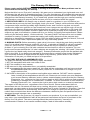
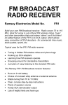
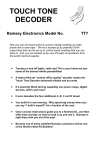
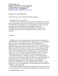
FMBA1 SCHEMATIC DIAGRAMS
FMBA-1 • 10
FMBA-1 • 11
a black band on it; this must be oriented as shown on the PC board
silkscreen.
13. In the same way, install D2, the other 1N4148 diode. Be sure the
band is placed correctly before soldering.
14. Install C1, .001µF capacitor [marked .001, 102 or 1nF].
15. Install L1, 0.1 µH inductor [looks like a resistor with brown-blacksilver-silver bands]. Remember, all parts should be seated as close to
the PC board as possible.
16. Install C2, 39 pF disc capacitor [marked 39].
17. Install L2, 0.1 µH inductor [looks like a resistor with brown-blacksilver-silver bands].
18. Install C4, 39 pF disc capacitor [marked 39].
19. Install C3, 68 pF disc capacitor [marked 68].
20. Install L3, 1.2 µH inductor [looks like a resistor with brown-red-goldsilver bands].
21. Install C17, 220 µF electrolytic capacitor. Be sure to follow the PC
board silkscreen for proper orientation.
22. Install R1, 150 ohm [brown-green-brown].
You will notice a silkscreen on the board for parts labeled D3 and R9. These
two parts give a power on indication. To make the PVC enclosure easier to
weatherproof, we have chosen not to install these parts. If you wish to install
your own 1K resistor and LED you may do so. You will need to drill a hole
for the LED and if you are mounting the amplifier outdoors, you will need to
seal around the LED to weatherproof the unit.
23. Install R3, 7.5K [violet-green-red].
24. Install VR1, the 12 volt regulator. You will need to form the leads so
that the part will fit into the board. Push the part down as far as it will
comfortably go.
25. Install C18, 10 µF electrolytic. Again, pay close attention to polarity
when installing this capacitor.
26. Install C5, .001µF disc capacitor [marked .001, 102 or 1nF].
27. Install C7, another .001µF disc capacitor [marked .001, 102 or 1nF].
28. Install C6, yet another .001µF disc capacitor [marked .001, 102 or
1nF].
FMBA-1 • 12
29. Install R2, a 1K ohm resistor [brown-black-red].
30. Install R6 and R7, both 12 ohm resistors [brown-red-black].
No, we didn’t forget to install U1. We will install it and Q2, both on the solder
side of the board, after we install the rest of the topside components.
31. Install C8, a 10 µF electrolytic, again checking polarity before
installing.
32. There is a silkscreen on the PC board for R8 and C9, however,
these parts will not be installed.
33. Q1 is the next part to be installed. As with electrolytic capacitors,
this transistor has only one correct way it can be installed. You will note
that it has two flat sides. You need to orient the larger flat side toward
R4. Bend the leads so that the part can fit as close to the the board as
possible without damage. Solder all three leads.
34. Install R4, 1K ohms [brown-black-red].
35. Install R5, another 1K ohm [brown-black-red].
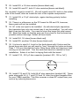
36. It is time to wind L4. Look for the ferrite bead with 6 holes and the
tinned buss wire that you will need to “lace” through the holes as shown.
Pass 1 1/2 turns through the holes, filling three holes and leaving a lead
coming out at each end. Trim the ends and bend as needed for neat
installation. Solder it so that it is laying flush with the board.
37. Install C10, .001 µF disc capacitor [marked .001, 102 or 1nF].
38. Install C13 and C14, both 68 pF disc capacitors [marked 68]. These
parts along with L5, 6, 7 and C12 and 15, form the output lowpass filter
for your FMBA amplifier. This filter ensures a clean RF output from your
source by reducing harmonics.
FMBA-1 • 13
39. Install C11, another .001 µF disc capacitor [marked .001, 102 or
1nF].
40. Install C12 and C15, the 39 pF disc capacitors [marked 39].
41. Install C16, the last .001 µF disc capacitor [marked .001, 102 or
1nF].
42. Install L5, L6 and L7, all 0.1 µH inductors [look like resistors with
brown-black-silver-silver bands].
That completes assembly of the through hole components on your amplifier
board. We will now flip the board over and install the heart of the FMBA1,
the two amplifiers.
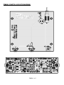
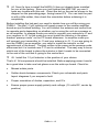
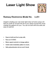
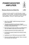
43. Turn the board over so that the soldered side is up. Locate Q2, the
MRF581, the larger of the two parts left. You should see a small “M”
near one lead of the transistor. This “M” will help you orient the part
correctly. When looking at the solder pads for this part you will notice
that one is longer than the other two. You will also notice that one lead
of Q2 is longer. The long lead on the part does not solder to the longer
pad. The transistor should be placed so that the longer lead (and “M”)
are facing J2, the output “F” jack. You will need to trim the long lead of
the transistor so that it will fit on the solder pad without hanging over.
Once you’re sure you have the part oriented properly, solder all four
leads.
Trim this lead
Bottom of board
03
FMBA-1 • 14
44. Now it’s time to install the MAR3 if it has not already been installed
for you at the factory. Since you just finished the MRF-581 you won’t
have any trouble with this one. Orient the dot on the part as shown in the
diagram on the preceding page, facing toward C5. You can tack the part
in with a little solder, then check the orientation before soldering it in
completely.
Before installing the last part you need to decide how you will be using your
FMBA1. The last 1.2 µH inductor will supply power to the smaller amplifier
board we just finished building. You will connect the antenna and control box
to opposite ends depending on whether you’re using the unit as a preamp or
as an amplifier. In preamp mode you need to connect your antenna to J1 and
your receiver to J2. In this mode you must install the inductor in the place
marked “preamp mode” on the PC board silkscreen. In amplifier mode you
will connect your transmitter to J1 and your antenna to J2. If you are going to
use the FMBA1 as an amplifier, you need to install the inductor on the
opposite end of the board. The part outline is the same as the preamp mode
silkscreen but it is located near C17 and is unlabeled. The easy way to know
which end of the board to place the inductor is that it needs to be connected
to the end of the unit that is going to the control box.
45. Install the 1.2 µH inductor in the position of your choice.
That’s it! All components should be installed. Before applying power it would
be a good idea to take one last glance over the entire pc board. Check for:
•
Missed solder joints.
•
Solder shorts between components. Check your schematic and parts
layout diagrams if you suspect a fault.
•
Proper orientation of diodes, capacitors, and ICs.
•
Ensure proper power supply polarity and voltage. (15 volts DC, center tip
positive)
FMBA-1 • 15
INITIAL TESTING AND OPERATION
Items needed:
−
Transmitter or whatever you wish to amplify OR Receiver you wish to
improve the sensitivity of.
−
External antenna
−
15 VDC power supply
−
Two lengths of coaxial cable with “F” connectors
−
One shielded RCA to RCA cable
A note concerning the cable needed: All Ramsey transmitters and antennas
are set up for 50 to 75 ohm impedance.
Power Amplifier Hookup
Before making any cable connections, make sure your FMBA amplifier board
is set up for amplifier mode. The 1.2 µH inductor from step 45 should be
installed in the place marked for it on the silkscreen, between J1 and C17.
To begin using your Broadcast Amplifier, you will need a length of 50 to 75
ohm coaxial cable or shielded audio cable to connect the input of the power
control box (J1) to your transmitter, a length of coax to connect the output of
the power control box (J2) to the input of the amplifier (J1, amplifier board),
and one more length of coax to connect the output of the amplifier (J2, amplifier board) to your external antenna. You will want to keep the length of all
the coax as short as is reasonably possible, especially between the amplifier
and the antenna.
Your FMBA was designed to operate on 15 volts DC. Connect the Ramsey
AC 12-5 adapter or another suitable power supply to the DC input of your
FMBA-1 power control unit. Then connect the shielded RCA to RCA cable
from the “External Antenna” output of your transmitter to J1 on the power
control box. If your non-Ramsey transmitter has some other type of jack for
the external antenna you will need to make up or buy a cable to connect it to
the FMBA-1. Next, take one of your lengths of coax and connect it to J2 on
the power control box. The other end of the coax connects to the input of the
FMBA board at J1. This will send not only the RF but also the DC to the amplifier board. The last piece of coax connects from the output of the FMBA,
J2, to your external antenna. Again, if your external antenna has some other
connector, you will need to get a suitable cable to connect the output of the
FMBA to your antenna.
Once all connections have been made and checked, you can power up your
transmitter and then your FM Broadcast Amplifier. The LED on the power
FMBA-1 • 16
control box should illuminate. If you have a signal strength meter on your
receiver and made note of the signal strength before addition of the amplifier,
you will see a large increase with the amp online. If you aren’t lucky enough
to be able to check your output in this manner, you can try increasing the
distance between your antenna and your receiver. And remember that with
such great amplification your transmitting distance should increase several
times; you may find yourself going far away from your house! This will be an
obvious way of telling how well your amplifier is working.
Preamp Hookup
The preamp hookup of your FMBA requires you to use the same cables but
connect them in a different configuration. You will now connect the antenna
to the input of the amplifier and your receiver to its output. You will be amplifying the incoming RF and feeding that increased signal to your receiver.
Before making any cable connections, make sure your FMBA amplifier board
is set up for preamp mode. The 1.2 µH inductor from step 46 should be installed in the place marked “preamp mode” on the PC board silkscreen.
Begin by connecting a 15 volt DC power supply, such as the Ramsey AC 125, or other suitable supply, to J3, the DC input on the power control box.
One of your coax cables can now be connected to the power control box at
J2. This cable will supply the DC voltage to the amplifier board as well as
carrying the RF down from the amp to the power control box. You can now
connect the shielded RCA to RCA cable to the antenna input of your receiver. If your receiver has a jack other than an RCA type, you will need to
make up or buy a cable to connect to the power control box.
The other length of coax cable can now be connected between J1 on the
amplifier board and your external antenna. Again, if your external antenna
has some other connector you will need to get a suitable cable to connect
the input of the FMBA amplifier board to your antenna.
To test the effectiveness of your preamp try tuning in a station that you can
barely receive with your regular antenna and then connect the FMBA-1. You
should pull the signal in and receive a bunch of other stations that you never
knew existed!
To get the maximum performance out of your FMBA-1, whether in preamp or
amplifier mode, you must use coaxial cable for all your connections. If you
don‘t wish to make up an RCA to RCA coax cable, you must use shielded
audio cable. The signal quality will be drastically reduced by using any other
type of cable!
FMBA-1 • 17
Troubleshooting
While we had hoped it wouldn’t come to this, here are a few things you can
check if your FMBA-1 doesn’t seem to be working. Please remember that
most problems occur because of bad soldering techniques and improperly
placed components. A clear head and a meter are all that you probably need
to solve the problem. Please run through all the troubleshooting ideas before
calling the factory since it is virtually impossible for our technicians to
“troubleshoot” step by step over the phone.
PROBLEM: The LED does not light when I turn it on.
SOLUTION: Even if the LED doesn’t work, the amplifier may. First measure
the voltage on the leg of the switch or on the lead of R1 closest to C2. If it
does not read near 15V you have a problem with the power supply, power
jack, or the switch is not on. Check to be sure that D1 is installed the correct
way (flat side away from the switch).
PROBLEM: The LED comes on but the amplifier is not working.
SOLUTION: Make sure that the MAV3 and Q2 are installed properly. The dot
on the MAV3 should point toward R3 and the “M” on Q2 should point toward
J2, the output jack. Next, check the placement and orientation of all parts. If
you have a voltmeter, you can check the DC voltage on the input and output
of U1 and Q2. They should read as follows:
Q2 input = 0.6 VDC
output = 11 VDC
U1 input = 1.6 VDC
output = 5 VDC
PROBLEM: Everything has been checked and the unit still doesn’t seem to
be operating properly.
SOLUTION: When all else fails, read the inside back cover of this manual for
information on sending the unit in for factory repair. For a nominal fee our
technicians will get your unit up and running for you.
Conclusion
We sincerely hope that you have enjoyed the construction of this Ramsey Kit.
As always, we have tried to compose our manual in the easiest, most “user
friendly” format that is possible. As our customers, we value your opinions,
comments, and additions that you would like to see in future publications.
Thanks again, from the folks at Ramsey.
FMBA-1 • 18
The Ramsey Kit Warranty
Please read carefully BEFORE calling or writing in about your kit. Most problems can be
solved without contacting the factory.
Notice that this is not a "fine print" warranty. We want you to understand your rights and ours too!
All Ramsey kits will work if assembled properly. The very fact that your kit includes this new manual
is your assurance that a team of knowledgeable people have field-tested several "copies" of this kit
straight from the Ramsey Inventory. If you need help, please read through your manual carefully.
All information required to properly build and test your kit is contained within the pages!
1. DEFECTIVE PARTS: It's always easy to blame a part for a problem in your kit, Before you
conclude that a part may be bad, thoroughly check your work. Today's semiconductors and passive
components have reached incredibly high reliability levels, and it’s sad to say that our human
construction skills have not! But on rare occasions a sour component can slip through. All our kit
parts carry the Ramsey Electronics Warranty that they are free from defects for a full ninety (90)
days from the date of purchase. Defective parts will be replaced promptly at our expense. If you
suspect any part to be defective, please mail it to our factory for testing and replacement. Please
send only the defective part(s), not the entire kit. The part(s) MUST be returned to us in suitable
condition for testing. Please be aware that testing can usually determine if the part was truly
defective or damaged by assembly or usage. Don't be afraid of telling us that you 'blew-it', we're all
human and in most cases, replacement parts are very reasonably priced.
2. MISSING PARTS: Before assuming a part value is incorrect, check the parts listing carefully to
see if it is a critical value such as a specific coil or IC, or whether a RANGE of values is suitable
(such as "100 to 500 uF"). Often times, common sense will solve a mysterious missing part
problem. If you're missing five 10K ohm resistors and received five extra 1K resistors, you can
pretty much be assured that the '1K ohm' resistors are actually the 'missing' 10 K parts ("Hum-m-m,
I guess the 'red' band really does look orange!") Ramsey Electronics project kits are packed with
pride in the USA. If you believe we packed an incorrect part or omitted a part clearly indicated in
your assembly manual as supplied with the basic kit by Ramsey, please write or call us with
information on the part you need and proof of kit purchase.
3. FACTORY REPAIR OF ASSEMBLED KITS:
To qualify for Ramsey Electronics factory repair, kits MUST:
1. NOT be assembled with acid core solder or flux.
2. NOT be modified in any manner.
3. BE returned in fully-assembled form, not partially assembled.
4. BE accompanied by the proper repair fee. No repair will be undertaken until we have received
the MINIMUM repair fee (1/2 hour labor) of $25.00, or authorization to charge it to your
credit card account.
5. INCLUDE a description of the problem and legible return address. DO NOT send a separate
letter; include all correspondence with the unit. Please do not include your own hardware
such as non-Ramsey cabinets, knobs, cables, external battery packs and the like. Ramsey
Electronics, Inc., reserves the right to refuse repair on ANY item in which we find excessive
problems or damage due to construction methods. To assist customers in such situations,
Ramsey Electronics, Inc., reserves the right to solve their needs on a case-by-case basis.
The repair is $50.00 per hour, regardless of the cost of the kit. Please understand that our
technicians are not volunteers and that set-up, testing, diagnosis, repair and repacking and
paperwork can take nearly an hour of paid employee time on even a simple kit. Of course, if we find
that a part was defective in manufacture, there will be no charge to repair your kit (But please
realize that our technicians know the difference between a defective part and parts burned out or
damaged through improper use or assembly).
4. REFUNDS: You are given ten (10) days to examine our products. If you are not satisfied, you
may return your unassembled kit with all the parts and instructions and proof of purchase to the
factory for a full refund. The return package should be packed securely. Insurance is
recommended. Please do not cause needless delays, read all information carefully.
FMBA-1 • 19
High Intercept Point FM Broadcast Amplifier Kit
Quick Reference Page Guide
Introduction.............................................4
Circuit Description ..................................4
Parts Layout Diagram.............................5
FMBA1 Parts List....................................6
Assembly Procedure ..............................8
Schematic Diagram ..............................10
Initial Testing and Operation ................16
Troubleshooting....................................18
Warranty ...............................................19
REQUIRED TOOLS
• Soldering Iron Ramsey WLC100
• Thin Rosin Core Solder Ramsey RTS12
• Needle Nose Pliers Ramsey MPP4 or RTS05
• Small Diagonal Cutters Ramsey RTS04
<OR> Technician’s Tool Kit TK405
ADDITIONAL SUGGESTED ITEMS
Holder for PC Board/Parts Ramsey HH3
Desoldering Braid Ramsey RTS08
Digital Multimeter Ramsey M133
•
•
•
Price: $5.00
Ramsey Publication No. MFMBA1
Assembly and Instruction manual for:
RAMSEY MODEL NO. FMBA1
TOTAL SOLDER POINTS
115
RAMSEY ELECTRONICS, INC.
590 Fishers Station Drive
Victor, New York 14564
Phone (585) 924-4560
Fax (585) 924-4555
www.ramseykits.com
ESTIMATED ASSEMBLY
TIME
Beginner .............. 3 hrs
Intermediate......... 2 hrs
Advanced............. 1 hr
FMBA-1 • 20