1
NI Vision
NI Vision Builder for Automated Inspection Tutorial
NI Vision Builder for Automated Inspection Tutorial
August 2009
373379F-01
Support
Worldwide Technical Support and Product Information
ni.com
National Instruments Corporate Headquarters
11500 North Mopac Expressway Austin, Texas 78759-3504 USA Tel: 512 683 0100
Worldwide Offices
Australia 1800 300 800, Austria 43 662 457990-0, Belgium 32 (0) 2 757 0020, Brazil 55 11 3262 3599,
Canada 800 433 3488, China 86 21 5050 9800, Czech Republic 420 224 235 774, Denmark 45 45 76 26 00,
Finland 358 (0) 9 725 72511, France 01 57 66 24 24, Germany 49 89 7413130, India 91 80 41190000,
Israel 972 3 6393737, Italy 39 02 41309277, Japan 0120-527196, Korea 82 02 3451 3400,
Lebanon 961 (0) 1 33 28 28, Malaysia 1800 887710, Mexico 01 800 010 0793, Netherlands 31 (0) 348 433 466,
New Zealand 0800 553 322, Norway 47 (0) 66 90 76 60, Poland 48 22 328 90 10, Portugal 351 210 311 210,
Russia 7 495 783 6851, Singapore 1800 226 5886, Slovenia 386 3 425 42 00, South Africa 27 0 11 805 8197,
Spain 34 91 640 0085, Sweden 46 (0) 8 587 895 00, Switzerland 41 56 2005151, Taiwan 886 02 2377 2222,
Thailand 662 278 6777, Turkey 90 212 279 3031, United Kingdom 44 (0) 1635 523545
For further support information, refer to the Technical Support and Professional Services appendix. To comment
on National Instruments documentation, refer to the National Instruments Web site at ni.com/info and enter
the info code feedback.
© 2002–2009 National Instruments Corporation. All rights reserved.
Important Information
Warranty
The media on which you receive National Instruments software are warranted not to fail to execute programming instructions, due to defects
in materials and workmanship, for a period of 90 days from date of shipment, as evidenced by receipts or other documentation. National
Instruments will, at its option, repair or replace software media that do not execute programming instructions if National Instruments receives
notice of such defects during the warranty period. National Instruments does not warrant that the operation of the software shall be
uninterrupted or error free.
A Return Material Authorization (RMA) number must be obtained from the factory and clearly marked on the outside of the package before any
equipment will be accepted for warranty work. National Instruments will pay the shipping costs of returning to the owner parts which are covered by
warranty.
National Instruments believes that the information in this document is accurate. The document has been carefully reviewed for technical accuracy. In
the event that technical or typographical errors exist, National Instruments reserves the right to make changes to subsequent editions of this document
without prior notice to holders of this edition. The reader should consult National Instruments if errors are suspected. In no event shall National
Instruments be liable for any damages arising out of or related to this document or the information contained in it.
EXCEPT AS SPECIFIED HEREIN, NATIONAL INSTRUMENTS MAKES NO WARRANTIES, EXPRESS OR IMPLIED, AND SPECIFICALLY DISCLAIMS ANY WARRANTY OF
MERCHANTABILITY OR FITNESS FOR A PARTICULAR PURPOSE. CUSTOMER’S RIGHT TO RECOVER DAMAGES CAUSED BY FAULT OR NEGLIGENCE ON THE PART OF NATIONAL
INSTRUMENTS SHALL BE LIMITED TO THE AMOUNT THERETOFORE PAID BY THE CUSTOMER. NATIONAL INSTRUMENTS WILL NOT BE LIABLE FOR DAMAGES RESULTING
FROM LOSS OF DATA, PROFITS, USE OF PRODUCTS, OR INCIDENTAL OR CONSEQUENTIAL DAMAGES, EVEN IF ADVISED OF THE POSSIBILITY THEREOF. This limitation of
the liability of National Instruments will apply regardless of the form of action, whether in contract or tort, including negligence. Any action against
National Instruments must be brought within one year after the cause of action accrues. National Instruments shall not be liable for any delay in
performance due to causes beyond its reasonable control. The warranty provided herein does not cover damages, defects, malfunctions, or service
failures caused by owner’s failure to follow the National Instruments installation, operation, or maintenance instructions; owner’s modification of the
product; owner’s abuse, misuse, or negligent acts; and power failure or surges, fire, flood, accident, actions of third parties, or other events outside
reasonable control.
Copyright
Under the copyright laws, this publication may not be reproduced or transmitted in any form, electronic or mechanical, including photocopying,
recording, storing in an information retrieval system, or translating, in whole or in part, without the prior written consent of National
Instruments Corporation.
National Instruments respects the intellectual property of others, and we ask our users to do the same. NI software is protected by copyright and other
intellectual property laws. Where NI software may be used to reproduce software or other materials belonging to others, you may use NI software only
to reproduce materials that you may reproduce in accordance with the terms of any applicable license or other legal restriction.
Trademarks
National Instruments, NI, ni.com, and LabVIEW are trademarks of National Instruments Corporation. Refer to the Terms of Use section
on ni.com/legal for more information about National Instruments trademarks.
Other product and company names mentioned herein are trademarks or trade names of their respective companies.
Members of the National Instruments Alliance Partner Program are business entities independent from National Instruments and have no agency,
partnership, or joint-venture relationship with National Instruments.
Patents
For patents covering National Instruments products/technology, refer to the appropriate location: Help»Patents in your software,
the patents.txt file on your media, or the National Instruments Patent Notice at ni.com/patents.
WARNING REGARDING USE OF NATIONAL INSTRUMENTS PRODUCTS
(1) NATIONAL INSTRUMENTS PRODUCTS ARE NOT DESIGNED WITH COMPONENTS AND TESTING FOR A LEVEL OF
RELIABILITY SUITABLE FOR USE IN OR IN CONNECTION WITH SURGICAL IMPLANTS OR AS CRITICAL COMPONENTS IN
ANY LIFE SUPPORT SYSTEMS WHOSE FAILURE TO PERFORM CAN REASONABLY BE EXPECTED TO CAUSE SIGNIFICANT
INJURY TO A HUMAN.
(2) IN ANY APPLICATION, INCLUDING THE ABOVE, RELIABILITY OF OPERATION OF THE SOFTWARE PRODUCTS CAN BE
IMPAIRED BY ADVERSE FACTORS, INCLUDING BUT NOT LIMITED TO FLUCTUATIONS IN ELECTRICAL POWER SUPPLY,
COMPUTER HARDWARE MALFUNCTIONS, COMPUTER OPERATING SYSTEM SOFTWARE FITNESS, FITNESS OF COMPILERS
AND DEVELOPMENT SOFTWARE USED TO DEVELOP AN APPLICATION, INSTALLATION ERRORS, SOFTWARE AND HARDWARE
COMPATIBILITY PROBLEMS, MALFUNCTIONS OR FAILURES OF ELECTRONIC MONITORING OR CONTROL DEVICES,
TRANSIENT FAILURES OF ELECTRONIC SYSTEMS (HARDWARE AND/OR SOFTWARE), UNANTICIPATED USES OR MISUSES, OR
ERRORS ON THE PART OF THE USER OR APPLICATIONS DESIGNER (ADVERSE FACTORS SUCH AS THESE ARE HEREAFTER
COLLECTIVELY TERMED “SYSTEM FAILURES”). ANY APPLICATION WHERE A SYSTEM FAILURE WOULD CREATE A RISK OF
HARM TO PROPERTY OR PERSONS (INCLUDING THE RISK OF BODILY INJURY AND DEATH) SHOULD NOT BE RELIANT SOLELY
UPON ONE FORM OF ELECTRONIC SYSTEM DUE TO THE RISK OF SYSTEM FAILURE. TO AVOID DAMAGE, INJURY, OR DEATH,
THE USER OR APPLICATION DESIGNER MUST TAKE REASONABLY PRUDENT STEPS TO PROTECT AGAINST SYSTEM FAILURES,
INCLUDING BUT NOT LIMITED TO BACK-UP OR SHUT DOWN MECHANISMS. BECAUSE EACH END-USER SYSTEM IS
CUSTOMIZED AND DIFFERS FROM NATIONAL INSTRUMENTS' TESTING PLATFORMS AND BECAUSE A USER OR APPLICATION
DESIGNER MAY USE NATIONAL INSTRUMENTS PRODUCTS IN COMBINATION WITH OTHER PRODUCTS IN A MANNER NOT
EVALUATED OR CONTEMPLATED BY NATIONAL INSTRUMENTS, THE USER OR APPLICATION DESIGNER IS ULTIMATELY
RESPONSIBLE FOR VERIFYING AND VALIDATING THE SUITABILITY OF NATIONAL INSTRUMENTS PRODUCTS WHENEVER
NATIONAL INSTRUMENTS PRODUCTS ARE INCORPORATED IN A SYSTEM OR APPLICATION, INCLUDING, WITHOUT
LIMITATION, THE APPROPRIATE DESIGN, PROCESS AND SAFETY LEVEL OF SUCH SYSTEM OR APPLICATION.
Contents
About This Manual
Conventions ...................................................................................................................xi
Related Documentation..................................................................................................xii
PART I
Vision Builder AI Basics
Chapter 1
Introduction to Vision Builder AI
Vision Builder AI Configuration Interface ....................................................................1-4
Elements of the Configuration Interface .........................................................1-5
Inspection State Diagram ................................................................................1-6
Vision Builder AI Inspection Interface..........................................................................1-8
Running an Inspection ...................................................................................................1-9
Configuration Interface ...................................................................................1-9
Inspection Interface .........................................................................................1-11
Chapter 2
Checking for the Presence of a Part
Creating a New Inspection.............................................................................................2-1
Acquiring Inspection Images .........................................................................................2-1
Defining a Feature on which to Base a Coordinate System ..........................................2-2
Setting a Coordinate System..........................................................................................2-5
Checking for the Cap Using Measure Intensity.............................................................2-6
Setting the Inspection Status..........................................................................................2-8
Testing the Inspection ....................................................................................................2-8
Saving the Inspection.....................................................................................................2-9
Chapter 3
Inspecting Objects for Correct Measurements
Creating a New Inspection.............................................................................................3-1
Acquiring and Calibrating Inspection Images ...............................................................3-1
Locating Features to Measure........................................................................................3-4
Measuring Parts of the Gasket .......................................................................................3-7
Setting the Inspection Status..........................................................................................3-8
Testing the Inspection ....................................................................................................3-8
Saving the Inspection.....................................................................................................3-9
© National Instruments Corporation
v
NI Vision Builder for Automated Inspection Tutorial
Contents
Chapter 4
Inspecting for Multiple Correct Instances of an Object
Creating a New Inspection ............................................................................................ 4-1
Acquiring Inspection Images......................................................................................... 4-1
Defining a Feature on which to Base a Coordinate System .......................................... 4-2
Setting a Coordinate System ......................................................................................... 4-3
Measuring the Separation between Connectors ............................................................ 4-3
Inspecting the Fuse Conductor ...................................................................................... 4-5
Making Logical PASS/FAIL Decisions ........................................................................ 4-8
Setting the Inspection Status ......................................................................................... 4-10
Testing the Inspection.................................................................................................... 4-10
Saving the Inspection .................................................................................................... 4-11
Chapter 5
Inspecting an Object that Spans Two Image Frames
Creating a New Inspection ............................................................................................ 5-1
Acquiring Inspection Images from Two Cameras......................................................... 5-2
Acquiring and Calibrating the Image of the Left Edge................................... 5-2
Acquiring and Calibrating the Image of the Right Edge ................................ 5-5
Locating the Right Edge of the Part .............................................................................. 5-7
Switching Images .......................................................................................................... 5-9
Locating the Left Edge of the Part ................................................................................ 5-9
Calculating the Width of the Part .................................................................................. 5-11
Setting Calculator Step Inputs and Outputs .................................................... 5-11
Adding Operators and Constants .................................................................... 5-13
Connecting the Equation Elements ................................................................. 5-14
Making Logical PASS/FAIL Decisions with the Calculator Step .................. 5-16
Setting the Inspection Status ......................................................................................... 5-17
Testing the Inspection.................................................................................................... 5-18
Saving the Inspection .................................................................................................... 5-18
Chapter 6
Branching and Decision Making
Creating a New Inspection ............................................................................................ 6-1
Creating the Inspection State Diagram.......................................................................... 6-1
Acquiring Inspection Images......................................................................................... 6-6
Checking for a Spray Bottle in the Image ..................................................................... 6-6
Checking for the Cap Using the Caliper........................................................................ 6-8
Setting the Inspection Status ......................................................................................... 6-9
Creating Custom Overlays for Inspection ..................................................................... 6-9
NI Vision Builder for Automated Inspection Tutorial
vi
ni.com
Contents
Configuring State Transitions ........................................................................................6-11
Testing the Inspection ....................................................................................................6-13
Saving the Inspection.....................................................................................................6-14
Chapter 7
Looping and Variables
Creating a New Inspection.............................................................................................7-1
Creating the Inspection State Diagram ..........................................................................7-1
Creating a Variable ........................................................................................................7-5
Acquiring Inspection Images .........................................................................................7-6
Finding Pin Edges ..........................................................................................................7-6
Initializing the Variable .................................................................................................7-7
Indexing Measurements .................................................................................................7-8
Setting a Coordinate System..........................................................................................7-8
Checking the Pin Gap ....................................................................................................7-9
Updating the Variable ....................................................................................................7-10
Identifying Failed Pins...................................................................................................7-10
Setting the Inspection Status..........................................................................................7-11
Displaying the Current Inspection Image ......................................................................7-11
Configuring State Transitions ........................................................................................7-12
Testing the Inspection ....................................................................................................7-13
Saving the Inspection.....................................................................................................7-14
PART II
Using Vision Builder AI
with Remote Targets
Chapter 8
Acquiring an Image with the NI 17xx Smart Camera
Hardware........................................................................................................................8-1
Connecting the Lens and Lighting.................................................................................8-2
Lighting ...........................................................................................................8-2
Connect the Power Supply and I/O................................................................................8-3
Power Only......................................................................................................8-3
Power with Additional I/O ..............................................................................8-4
Connecting to the Development Computer ...................................................................8-6
Firewall Configuration ....................................................................................8-6
Direct Connection............................................................................................8-7
Network Connection........................................................................................8-8
Subnet Considerations.......................................................................8-9
Configuring the IP Address ...........................................................................................8-9
© National Instruments Corporation
vii
NI Vision Builder for Automated Inspection Tutorial
Contents
Installing Software on the NI Smart Camera ................................................................ 8-11
Acquiring an Image ....................................................................................................... 8-11
Saving the Inspection .................................................................................................... 8-12
Triggered Acquisitions .................................................................................................. 8-12
Connecting the Trigger Signal ........................................................................ 8-12
Configuring the Acquisition............................................................................ 8-13
Acquiring images ............................................................................................ 8-14
Preventing an Acquisition Timeout............................................................................... 8-14
Creating the Inspection State Diagram ........................................................... 8-14
Chapter 9
Acquiring an Image with the NI CVS-1450 Compact Vision System
Hardware ....................................................................................................................... 9-1
Connecting a Camera and Monitor................................................................................ 9-2
Connecting a Power Supply .......................................................................................... 9-3
Connecting to a Third-Party Power Supply .................................................... 9-4
Connecting to a Network............................................................................................... 9-5
Subnet Considerations..................................................................................... 9-5
Connecting to a Development Computer ...................................................................... 9-5
Configuring an IP Address ............................................................................................ 9-7
Installing Software to the NI CVS-1450 Device........................................................... 9-8
Acquiring an Image ....................................................................................................... 9-8
Saving the Inspection .................................................................................................... 9-9
Chapter 10
Performing a Triggered Acquisition Using the NI CVS-1450 Compact
Vision System
Hardware ....................................................................................................................... 10-2
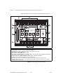
Connecting the Hardware .............................................................................................. 10-2
Connecting the Trigger Signal ........................................................................ 10-3
Creating a New Inspection ............................................................................................ 10-5
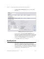
Configuring the Trigger Signal ..................................................................................... 10-5
Resetting the I/O............................................................................................................ 10-6
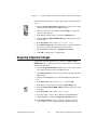
Acquiring Inspection Images......................................................................................... 10-7
Saving the Inspection .................................................................................................... 10-8
Testing the Acquisition.................................................................................................. 10-8
Preventing an Acquisition Timeout............................................................................... 10-9
Creating the Inspection State Diagram ........................................................... 10-9
NI Vision Builder for Automated Inspection Tutorial
viii
ni.com
Contents
Chapter 11
Inspection Selection
Connect to a Remote Target ..........................................................................................11-1
Installing Examples on the Remote Target....................................................................11-1
Opening an Inspection ...................................................................................................11-3
Adding a Communication Device..................................................................................11-3
Configuring TCP/IP Communication ............................................................................11-3
Mapping I/O Values to Inspections ...............................................................................11-4
Running the Inspection ..................................................................................................11-5
Generating TCP Commands and Testing the Inspection...............................................11-6
Appendix A
Technical Support and Professional Services
Glossary
© National Instruments Corporation
ix
NI Vision Builder for Automated Inspection Tutorial
About This Manual
This manual contains many techniques for using NI Vision Builder for
Automated Inspection (Vision Builder AI) to solve visual inspection tasks
including inspection, gauging, part presence, guidance, and counting.
Follow the instructions in this manual to familiarize yourself with the
Vision Builder AI and perform common inspection tasks.
Conventions
The following conventions appear in this manual:
»
The » symbol leads you through nested menu items and dialog box options
to a final action. The sequence File»Page Setup»Options directs you to
pull down the File menu, select the Page Setup item, and select Options
from the last dialog box.
This icon denotes a tip, which alerts you to advisory information.
This icon denotes a note, which alerts you to important information.
This icon denotes a caution, which advises you of precautions to take to
avoid injury, data loss, or a system crash.
bold
Bold text denotes items that you must select or click in the software, such
as menu items and dialog box options. Bold text also denotes parameter
names.
italic
Italic text denotes variables, emphasis, a cross-reference, or an introduction
to a key concept. Italic text also denotes text that is a placeholder for a word
or value that you must supply.
monospace
Text in this font denotes text or characters that you should enter from the
keyboard, sections of code, programming examples, and syntax examples.
This font is also used for the proper names of disk drives, paths, directories,
programs, subprograms, subroutines, device names, functions, operations,
variables, filenames, and extensions.
© National Instruments Corporation
xi
NI Vision Builder for Automated Inspection Tutorial
About This Manual
Related Documentation
The following documents contain information that you might find helpful
as you read this manual:
•
NI Vision Builder for Automated Inspection Readme—Contains
information about the minimum system requirements, installation
instructions, device support, and known issues for NI Vision Builder
for Automated Inspection. The NI Vision Builder for Automated
Inspection Readme is available at Start»All Programs»National
Instruments»Vision Builder AI»Documentation.
•
NI Vision Builder for Automated Inspection:
Configuration Help—Contains information about using the Vision
Builder AI Configuration interface to create a machine vision
application. NI Vision Builder for Automated Inspection:
Configuration Help is available by selecting Help»Online Help from
the Vision Builder AI Configuration interface.
•
NI Vision Builder for Automated Inspection:
Inspection Help—Contains information about running applications
created using Vision Builder AI in the Vision Builder AI Inspection
Interface. NI Vision Builder for Automated Inspection:
Inspection Help is available by selecting Help»Online Help from the
Vision Builder AI Inspection interface.
•
NI Developer Zone—Visit ni.com/zone for the latest example
programs, tutorials, technical presentations, and a community area
where you can share ideas, questions, and source code with developers
around the world.
•
NI 17xx Smart Camera User Manual—Describes the electrical and
mechanical aspects of the NI 17xx smart camera, troubleshooting
guidelines, and information about the LEDs, DIP switches, and
connectors on the NI 17xx.
•
NI CVS-1450 Series User Manual—Describes the electrical and
mechanical aspects of the NI CVS-1450 Series, troubleshooting
guidelines, and information about the LEDs, DIP switches, and
connectors on the CVS-1450 device.
•
NI EVS-1464 User Manual—Describes the electrical and mechanical
aspects of the NI EVS-1464 embedded vision system, troubleshooting
guidelines, and information about the LEDs, DIP switches, and
connectors on the EVS-1464 device.
NI Vision Builder for Automated Inspection Tutorial
xii
ni.com
About This Manual
•
NI Vision I/O Terminal Block and Prototyping Accessory User
Guide—Describes the features of the NI Vision I/O Terminal Block
and Prototyping Accessory, what you need to get started, and the
installation and operation of the device.
•
NI Smart Camera I/O Accessory User Guide—Describes the features
of the NI Smart Camera I/O Accessory, what you need to get started,
and the installation and operation of the device.
© National Instruments Corporation
xiii
NI Vision Builder for Automated Inspection Tutorial
Part I
Vision Builder AI Basics
This section provides a series of lessons designed to introduce you to the
Vision Builder for Automated Inspection (Vision Builder AI) environment
and describe how to perform many common machine vision tasks using
Vision Builder AI.
Part I, Vision Builder AI Basics, contains the following chapters:
•
Chapter 1, Introduction to Vision Builder AI, introduces the Vision
Builder AI environment and describes how to run an inspection.
•
Chapter 2, Checking for the Presence of a Part, introduces the Match
Pattern, Measure Intensity, and Set Coordinate System steps.
Follow the instructions in this chapter to create an inspection that
checks for the presence of a spray bottle cap regardless of the bottle
position in the inspection images.
•
Chapter 3, Inspecting Objects for Correct Measurements, introduces
image calibration, and the Detect Objects and Geometry steps.
Follow the instructions in this chapter to create an inspection that
measures the distance between holes in a gasket to verify that the
gasket conforms to manufacturing specifications.
•
Chapter 4, Inspecting for Multiple Correct Instances of an Object,
introduces the Find Straight Edge, Caliper, and Decision Making
steps. Follow the instructions in this chapter to create an inspection
that measures the distance between the blade connectors of a fuse and
checks the integrity of the fuse conductor regardless of the fuse
position or whether the fuse is inverted.
•
Chapter 5, Inspecting an Object that Spans Two Image Frames,
introduces the Select Image and Calculator steps. Follow the
instructions in this chapter to create an inspection that measures
the width of a wooden plank that spans two images.
© National Instruments Corporation
I-1
NI Vision Builder for Automated Inspection Tutorial
Part I
Vision Builder AI Basics
•
Chapter 6, Branching and Decision Making, introduces the inspection
state diagram and the Custom Overlay step. Follow the instructions in
this chapter to create an inspection that checks the image for the
presence of a spray bottle and, if a bottle is present, transitions to
another state to determine if the bottle has a cap. If there is no spray
bottle present in the image, the inspection moves on to the next image.
•
Chapter 7, Looping and Variables, uses the inspection state diagram to
implement a looping inspection and introduces the Set Variable and
Index Measurements steps. Follow the instructions in this chapter to
create an inspection that inspects images of electronic components to
determine if the distance between pins on the component is within a
predetermined range. If the pin is too close or too far away from an
adjacent pin, then the inspection fails. The inspection does not need to
check every pin on the microchip before failing the inspection. The
inspection fails at the first failed pin.
NI Vision Builder for Automated Inspection Tutorial
I-2
ni.com
Introduction to Vision Builder AI
1
This chapter introduces the Vision Builder AI environment and describes
how to run an inspection.
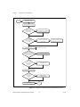
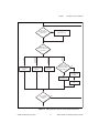
Figures 1-1 and 1-2 show general instructions for creating a Vision Builder
AI inspection. Figure 1-1 describes the basic steps for designing a Vision
Builder AI inspection. The Add Inspection Steps module of Figure 1-1 is
expanded in Figure 1-2.
© National Instruments Corporation
1-1
NI Vision Builder for Automated Inspection Tutorial
Chapter 1
Introduction to Vision Builder AI
Start
Open Vision Builder AI
Configuration interface
Add step to acquire an image
of the parts under inspection
Do you
want to make
measurements in
real-world units?
Yes
Create or select a spatial
calibration from the Calibration
tab of the acquisition step
Yes
Add step from Locate Features
palette to locate the part
in the image
No
Do the parts
appear in different
locations from image
to image?
Add Set Coordinate System step
to create a coordinate system
based on the part location
No
Add Inspection steps
Do you
want to create
intermediate measurements
based on the results of
previous steps?
Refer to Figure 1-2 for details.
Yes
Add Calculator step
No
Do you
want to customize
the inspection
decision?
Yes
Add Logic Calculator step
or Calculator step
No
Add Set Inspection Status step
Do you
want to send
measurements to
an external
device?
Yes
Add one of the
Communication steps
No
Save inspection
Stop
Figure 1-1. Instructions for Creating a Basic Vision Builder AI Inspection
NI Vision Builder for Automated Inspection Tutorial
1-2
ni.com
Chapter 1
Does the
image need to be
enhanced?
Yes
Introduction to Vision Builder AI
Add Vision Assistant
or
Filter Image step
No
Add step from
Locate Features
palette
palette.
Gauging
Identification
Presence/
Absence
Location
What type of
inspection do you need
to perform?
Add step from
Check for Presence
palette
Add step from
Identify Parts
palette
Do you
want to measure
distances between
object edges?
Yes
No
Add steps from
Locate Features
palette
Add Caliper step
Add Geometry
step
Do you want
to add another
step?
Yes
No
Figure 1-2. Adding Inspection Steps to a Vision Builder AI Inspection
© National Instruments Corporation
1-3
NI Vision Builder for Automated Inspection Tutorial
Chapter 1
Introduction to Vision Builder AI
Vision Builder AI Configuration Interface
Vision Builder AI has two modes of operation: Configuration and
Inspection. Use the Configuration interface to configure and test your
inspection. Use the Inspection interface to deploy the software and perform
online or offline visual inspection.
Complete the following instructions to open the Vision Builder AI
Configuration interface.
1.
Select Start»All Programs»National Instruments»Vision Builder
AI to launch the Vision Builder AI Welcome screen.
2.
Click Configure Inspection.
NI Vision Builder for Automated Inspection Tutorial
1-4
ni.com
Chapter 1
Introduction to Vision Builder AI
Elements of the Configuration Interface
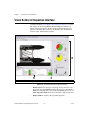
Figure 1-3 shows the Vision Builder AI Configuration interface. The
Configuration interface contains four areas: Main window, Overview
window, Inspection Steps palette, and State Configuration window.
2
1
4
1
2
Main Window
Overview Window
3
3
4
Inspection Steps Palette
State Configuration Window
Figure 1-3. Vision Builder AI Configuration Interface
© National Instruments Corporation
1-5
NI Vision Builder for Automated Inspection Tutorial
Chapter 1
Introduction to Vision Builder AI
•
Main window—Displays the image being processed, property pages
for some inspection steps, or the state diagram for the inspection. Use
the Main window to define regions of interest in an image, configure
step parameters for some steps, and create/modify the state diagram for
an inspection.
•
Overview window—Displays a thumbnail view of either the current
inspection image or the state diagram for the inspection.
•
Inspection Steps palette—Lists and describes the steps that you use
to create your inspection. When you click on most steps, the palette
transforms into the property page for the step.
•
State Configuration window—Displays the list of steps in the
currently selected state in the inspection.
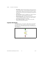
Inspection State Diagram
Vision Builder AI uses a state diagram to define inspections with unique
states and transitions that govern the execution flow of the inspection.
Simple inspections can be defined using the single-state default inspection,
shown in Figure 1-4.
Figure 1-4. Default Inspection State Diagram
NI Vision Builder for Automated Inspection Tutorial
1-6
ni.com
Chapter 1
Introduction to Vision Builder AI
More complex inspections can be created by adding additional states and
transitions to the default state diagram. Figure 1-5 shows an example of an
inspection that uses the state diagram to perform branching and looping in
the inspection.
Figure 1-5. Example of a Vision Builder AI Inspection State Diagram
Within a state diagram, each state can lead to one or multiple states or can
end the inspection cycle. Each state diagram relies on in-state calculations
or user input to determine the next state to execute. Vision Builder AI
executes the state diagram continuously from the Start point to the
End point.
Each state in an inspection is intended to contain a discrete set of inspection
steps. To access the steps contained in a state, select the state on the
state diagram. The steps present in the state will appear in the State
Configuration window. The currently selected state is highlighted on the
state diagram.
Chapter 6, Branching and Decision Making, and Chapter 7, Looping and
Variables, provide examples of using the state diagram.
© National Instruments Corporation
1-7
NI Vision Builder for Automated Inspection Tutorial
Chapter 1
Introduction to Vision Builder AI
Vision Builder AI Inspection Interface
As mentioned in the Vision Builder AI Configuration Interface section of
this chapter, use the Vision Builder AI built-in Inspection Interface to
deploy and run an inspection. Figure 1-6 shows the built-in Inspection
interface, which has three main areas: the Results panel, the Inspection
Statistics panel, and the Display window.
3
1
1
Results Panel
2
2
Display Window
3
Inspection Statistics Panel
Figure 1-6. Vision Builder AI Built-in Inspection Interface
•
Results panel—Lists the steps in the inspection by name. For each
inspection step, Vision Builder displays the step type, result (PASS or
FAIL), measurement made, and a comment explaining the reason of a
FAIL. Inspection Status shows the result of the complete inspection.
•
Display window—Displays the part under inspection.
NI Vision Builder for Automated Inspection Tutorial
1-8
ni.com
Chapter 1
•
Introduction to Vision Builder AI
Inspection Statistics panel—Contains three indicators that display
the yield (ratio between PASS and FAIL), active versus idle time, and
processing time of the inspection.
Running an Inspection
Vision Builder AI allows you to run inspections from both the
Configuration and Inspection interfaces. The following sections describe
the options for running an inspection in Vision Builder AI.
Configuration Interface
Run an inspection from the Configuration interface during development to
test and debug inspections. The Highlight Execution, Pause, and Single
Step options are useful for debugging inspections. Table 1-1 lists the run
options available for the Configuration interface:
Table 1-1. Configuration Interface Run Modes
Button
—
Name
Description
Run Inspection Once
Runs the inspection through one iteration of
the state diagram.
Run Inspection in Loop
Runs the inspection continuously.
Run Inspection Until Failure
Runs the inspection until the Inspection
Status variable has a value of FAIL.
Run Inspection Multiple Times
Runs the inspection a specified number of
times. This option is available only from the
Operate menu.
Stop Inspection
Stops the inspection.
Highlight Execution
Highlights the inspection execution when
you run the inspection. If the Highlight
Execution button appears yellow, execution
highlighting is enabled.
Pause
Pauses or resumes execution of the
inspection. If the Pause button appears red,
execution is paused.
© National Instruments Corporation
1-9
NI Vision Builder for Automated Inspection Tutorial
Chapter 1
Introduction to Vision Builder AI
Table 1-1. Configuration Interface Run Modes (Continued)
Button
Name
Description
Single Step
Steps through the inspection. Single Step is
only available when the Pause button is
pressed.
Use Previous Image
Uses the previous inspection image the next
time the inspection executes.*
Use Current Image
Uses the current inspection image the next
time the inspection executes.*
Use Next Image
Uses the next inspection image the next time
the inspection executes.*
Select Next Image
Specifies the inspection image to process the
next time the inspection executes.*
* This button applies only to inspections that either contain a Simulate Acquisition step, or have Smart Camera Emulator,
Embedded Vision System Emulator, or Compact Vision System Emulator selected as the Execution Target.
NI Vision Builder for Automated Inspection Tutorial
1-10
ni.com
Chapter 1
Introduction to Vision Builder AI
Inspection Interface
After an inspection is configured, use the Inspection interface to run the
inspection and/or deploy your system. Complete the following instructions
to run an inspection from the Inspection interface:
If the Vision Builder AI Configuration interface is already open, select File»Switch
to Inspection Interface to open the current inspection in the Inspection interface.
Tip
1.
Select Start»All Programs»National Instruments»Vision Builder
AI to launch the Vision Builder AI Welcome screen.
2.
Click Inspect Product.
3.
Open an inspection.
4.
Click the Start Inspection button. Vision Builder AI begins running
the inspection and updating the three areas of the Inspection interface
with the most recent inspection data.
By default, Vision Builder AI displays all the inspection images in the
Display window. You can change the display settings in the View
menu to view only images that fail or to have no display. You also can
change the magnification of the displayed images in the Options
menu.
Notice the performance data displayed in the Inspection Statistics
panel. This data can help you determine how efficiently your
inspection is running. Based on this data, you can make adjustments to
improve the inspection speed.
5.
© National Instruments Corporation
Click the Stop Inspection button to stop the inspection.
1-11
NI Vision Builder for Automated Inspection Tutorial
Checking for the Presence
of a Part
2
This chapter introduces the Match Pattern, Measure Intensity, and Set
Coordinate System steps. Follow the instructions in this chapter to create
an inspection that checks for the presence of a spray bottle cap regardless
of the bottle position in the inspection images.
Launch Vision Builder AI if it is not open. Refer to the Vision Builder AI
Configuration Interface section of Chapter 1, Introduction to Vision Builder AI,
for more information.
Note
Creating a New Inspection
Select File»New. Vision Builder AI opens a new, blank inspection.
Acquiring Inspection Images
In the Inspection Steps palette, the Acquire Images tab contains several
acquisition steps you can use to acquire images from many different types
of cameras. The tab also contains a Simulate Acquisition step, which
simulates image acquisition by loading images from file. The Select Image
step enables you to switch to a previously acquired image that you need to
process later in the inspection.
For simplicity, this tutorial instructs you to use the Simulate Acquisition
step. However, in your real-world inspection, use one of the other image
acquisition steps to acquire images of the object under inspection.
Complete the following instructions to configure a Simulate Acquisition
step that simulates acquiring images of spray bottles.
1.
In the Inspection Steps palette, select the Acquire Images tab.
2.
Click the Simulate Acquisition step. The property page for the step
opens.
3.
In the Step Name control, enter Acquire Spray Bottle.
© National Instruments Corporation
2-1
NI Vision Builder for Automated Inspection Tutorial
Chapter 2
Checking for the Presence of a Part
4.
Click the Browse button. The Select an Image File dialog box opens.
5.
Navigate to <Vision Builder AI>\DemoImg\Tutorial 1, where
<Vision Builder AI> is the location where Vision Builder AI is
installed.
6.
Select the first image, Image 01.jpg, and click Open.
7.
Make sure the Cycle Through Folder Images control is enabled so
that Vision Builder AI loads a different simulation image from the
folder each time the step is run.
8.
Enable the Cache Images control if you want to load all of the images
into memory when the inspection opens. By default, each image is
loaded individually when the step executes.
9.
Click OK to add the step to the inspection.
Defining a Feature on which to Base a
Coordinate System
In a machine vision inspection, you typically limit your inspection and
processing to a region of interest (ROI) rather than the entire image for the
following reasons:
•
To improve your inspection results by avoiding extraneous objects
•
To increase inspection speed
To limit the inspection area, the parts of the object you are interested in
must always be inside the ROI you define.
If the object under inspection is fixtured and always appears at the same
location and orientation in the images you need to process, defining an ROI
is straightforward. However, if the object under inspection appears shifted
or rotated within the images, the regions of interest need to shift and rotate
with the object under inspection.
For the regions of interest to move in relation to the object, you need to set
a coordinate system relative to a significant and original feature of the
object under inspection. Choose a feature that is always in the field of view
of the camera despite the different locations that the objects may appear in
from image to image. Also, make sure the feature is not affected by major
defects that could drastically modify the visual appearance of the feature.
NI Vision Builder for Automated Inspection Tutorial
2-2
ni.com
Chapter 2
Checking for the Presence of a Part
Complete the following instructions to configure a Match Pattern step that
locates a bottle feature on which you can base a coordinate system.
1.
In the Inspection Steps palette, select the Locate Features tab.
2.
Click the Match Pattern step. The NI Vision Template Editor opens.
3.
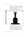
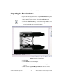
Draw a rectangle around the base of the sprayer, as shown in
Figure 2-1. This region becomes the pattern matching template.
Figure 2-1. Creating a Template Pattern
4.
Click Next.
5.
Click Finish to accept the template.
6.
On the Main tab, enter Locate Sprayer Base in the Step Name
control.
© National Instruments Corporation
2-3
NI Vision Builder for Automated Inspection Tutorial
Chapter 2
Checking for the Presence of a Part
The green ROI specifies the area of the image in which Vision Builder AI
tries to locate the template. Assuming that the bottles are fixtured in such a
way that they can move only horizontally within the field of view, you can
limit the ROI so that it surrounds only the area of the image that may
contain a template match during inspection.
7.
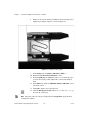
Redraw or decrease the default green ROI so that it surrounds only the
lower portion of the image, as shown in Figure 2-2.
Figure 2-2. Limiting the Search Region
8.
On the Template tab, drag the red crosshair mark in the template
image to the left edge of the sprayer base, as shown in Figure 2-3. This
changes the focal point of the template.
9.
The focal point indicates the part of the template that you want to
return as the match location. By default, the focal point is the center of
the template. You can modify the focal point by moving the red
crosshair or by specifying a Match Offset. Later in this inspection,
you use the match location as the origin of a coordinate system.
NI Vision Builder for Automated Inspection Tutorial
2-4
ni.com
Chapter 2
Checking for the Presence of a Part
1
1
Focal Point
Figure 2-3. Adjusting the Focal Point of the Template
10. On the Settings tab, set Number of Matches to Find to 1.
11. On the Limits tab, enable the Minimum Number of Matches control,
and set the value to 1.
12. Click OK to add the step to the inspection.
Setting a Coordinate System
Complete the following instructions to configure a Set Coordinate System
step based on the Match Pattern step you configured.
1.
In the Inspection Steps palette, select the Locate Features tab.
2.
Click the Set Coordinate System step. The property page for the step
opens.
3.
On the Main tab, enter Coordinate System in the Step Name
control.
© National Instruments Corporation
2-5
NI Vision Builder for Automated Inspection Tutorial
Chapter 2
Checking for the Presence of a Part
4.
On the Settings tab, select Horizontal and Vertical Motion from the
Mode control because the bottles appear shifted but not rotated from
one image to another.
Notice the Origin list. Match [1], the match location of the previous
Locate Sprayer Base step, is the default origin of the coordinate
system because it is the only location point created by previous steps
in the inspection.
5.
Click OK to add the step to the inspection.
Checking for the Cap Using Measure Intensity
The image of the spray bottle was acquired using a backlight. The cap
appears dark on the bright background. Complete the following
instructions to configure a Measure Intensity step to check for the
presence of a spray bottle cap.
1.
In the Inspection Steps palette, select the Check for Presence tab.
2.
Click the Measure Intensity step. The property page for the step
opens.
3.
On the Main tab, enter Check Cap Presence in the Step Name
control.
4.
Enable the Reposition Region of Interest control.
Enabling this control allows you to link the regions of interest specified
in this step to a previously defined coordinate system so that
Vision Builder AI can adjust the location and orientation of the ROI
from image to image relative to the specified coordinate system.
The Reference Coordinate System list shows all the previously
defined coordinate systems. Coordinate System is the default
reference coordinate system because it is the only Set Coordinate
System step in the current inspection.
Notice that the Measure Intensity step supports a variety of different tools
that enable you to draw different shaped regions of interest, such as a point,
line, broken line, freehand line, rectangle, ellipse, annulus, polygon, and
freehand region. These tools are available in the main menu bar.
5.
Using the default Rectangle Tool, hold down the <Ctrl> key, and draw
three regions of interest that enclose edges of the cap, as shown in
Figure 2-4. Pressing the <Ctrl> key enables you to draw multiple
regions of interest for the step.
NI Vision Builder for Automated Inspection Tutorial
2-6
ni.com
Chapter 2
Checking for the Presence of a Part
Figure 2-4. Defining Regions in Which to Measure Intensity
6.
Click the Limits tab.
At the bottom of the tabbed page, Vision Builder AI returns the
intensity statistics of the pixels inside the regions of interest. Pixel
intensities can range from 0–255, where 0 equals black and 255 equals
white.
The Minimum Intensity value at the bottom of the page returns the
lowest pixel value inside the regions of interest. The backlit edges of
the plastic cap appear in silhouette as dark pixels (which have low pixel
intensities) on a bright background (which has high pixel intensities).
Therefore, when the cap is present, the minimum intensity for the
regions is low. When the cap is not present, the minimum intensity for
the regions is high because the regions contain only bright background
pixels.
7.
Enable the Minimum Intensity control. Set the Maximum value
to 50.00.
8.
Click OK to add the step to the inspection.
© National Instruments Corporation
2-7
NI Vision Builder for Automated Inspection Tutorial
Chapter 2
Checking for the Presence of a Part
9.
Click the Run State Once button located in the State Configuration
window.
Vision Builder AI loads the next image, Image 02.jpg, from the
<Vision Builder AI>\DemoImg\Tutorial 1 folder and runs the
previous inspection steps in the state on the new image.
Notice that the bottle appears closer to the left edge of the image.
Vision Builder AI repositions the regions of interest based on the new
location of the bottle. The Step Status for the image is PASS because
the presence of the cap inside the regions of interest causes the
Minimum Intensity value to fall within the limits you set.
Setting the Inspection Status
Complete the following instructions to add a Set Inspection Status step to
determine whether the inspection passes or fails.
1.
In the Inspection Steps palette, select the Use Additional Tools tab.
2.
Click the Set Inspection Status step. The property page for the step
opens.
3.
In the Inspection Status control, select the FAIL if any previous step
fails option.
4.
Click OK to add the step to the inspection.
Testing the Inspection
Test the remaining images in the Tutorial 1 folder to make sure the
inspection returns the correct results. Click the Run Inspection Once
button to test the remaining images. Table 2-1 displays the expected results
for each image.
Table 2-1. Expected Results for the Spray Bottle Inspection
Image Name
Inspection Status
Explanation
Image 03.jpg
PASS
Cap is present.
Image 04.jpg
PASS
Cap is present.
Image 05.jpg
FAIL
Cap is missing.
NI Vision Builder for Automated Inspection Tutorial
2-8
ni.com
Chapter 2
Checking for the Presence of a Part
Saving the Inspection
Complete the following instructions to save the example inspection.
1.
Select File»Save or click the Save button on the toolbar.
2.
Navigate to the location where you want to save the inspection.
3.
In the File Name control, enter Tutorial 1.vbai.
4.
Click Save to save the inspection.
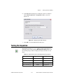
Select File»Inspection Properties to add a short description or comments about the
inspection.
Tip
© National Instruments Corporation
2-9
NI Vision Builder for Automated Inspection Tutorial
Inspecting Objects for Correct
Measurements
3
This chapter introduces image calibration, and the Detect Objects and
Geometry steps. Follow the instructions in this chapter to create an
inspection that measures the distance between holes in a gasket to verify
that the gasket conforms to manufacturing specifications.
Launch Vision Builder AI if it is not open. Refer to the Vision Builder AI
Configuration Interface section of Chapter 1, Introduction to Vision Builder AI,
for more information.
Note
Creating a New Inspection
Select File»New. Vision Builder AI opens a new, blank inspection.
Acquiring and Calibrating Inspection Images
For simplicity, this tutorial instructs you to use the Simulate Acquisition
step. However, in your real-world inspection, use one of the other image
acquisition steps to acquire images of the object under inspection.
Complete the following instructions to configure a Simulate Acquisition
step that simulates acquiring images of gaskets.
1.
In the Inspection Steps palette, select the Acquire Images tab.
2.
Click the Simulate Acquisition step. The property page for the step
opens.
3.
In the Step Name control, enter Acquire Gasket.
4.
Click the Browse button. The Select an Image File dialog box opens.
5.
Navigate to <Vision Builder AI>\DemoImg\Tutorial 2, where
<Vision Builder AI> is the location where Vision Builder AI is
installed.
6.
Select the first image, Image 01.jpg, and click Open.
© National Instruments Corporation
3-1
NI Vision Builder for Automated Inspection Tutorial
Chapter 3
Inspecting Objects for Correct Measurements
7.
Make sure the Cycle Through Folder Images control is enabled so
that Vision Builder AI loads a different simulation image from the
folder each time the step is run.
By default, Vision Builder AI returns measurements in pixel units. If you
want the inspection to return measurements in real-world units, you need to
map pixel units to real-world units through a process called spatial
calibration.
8.
Click the Calibration tab.
9.
Click Create Calibration to launch the calibration wizard.
10. In the Calibration Name control, enter Gasket Calibration.
11. Click Next.
For this example, assume that the camera that acquired the inspection
images is perpendicular to the image plane and lens distortion is negligible.
Based on these assumptions, you can use Simple Calibration to calibrate
your images. Simple Calibration transforms a pixel coordinate to a
real-world coordinate through scaling in the x (horizontal) and y (vertical)
directions.
12. Select the Simple Calibration option, and click Next.
13. Make sure Use Current Image is selected, and click Next.
14. Make sure Pixel Type is set to Square because the camera that
acquired the images for this exercise has square pixels.
15. Click Next.
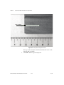
16. In the Specify the Pixel Ratio step, carefully click the 0 mm and
50 mm markings on the ruler at the bottom of the image, as shown in
Figure 3-1.
You may need to use the zoom buttons below the image to accurately click the ruler
markings. After zooming in, scroll down to see the ruler at the bottom of the image.
Tip
NI Vision Builder for Automated Inspection Tutorial
3-2
ni.com
Chapter 3
Inspecting Objects for Correct Measurements
Figure 3-1. Specifying the Pixel Ratio
17. In the Correspondence Image - Real World control, enter 50 for the
value, and select millimeter for the Unit.
18. Click Next.
In the Set Calibration Axis step, you can define the origin and angle of the
calibration axis anywhere in the image. By default, the top, left pixel in the
image is the calibration axis origin, and the horizontal axis of the image is
the calibration axis angle. Use the default calibration axis settings for this
exercise.
In some applications, you may want to measure between a fixed reference feature on
the part and other features in the image. Setting the origin of the calibration axis to the
location of the reference feature simplifies making measurements because the starting
point for the measurements becomes 0.
Tip
19. Click OK to learn the calibration information and exit the calibration
wizard.
20. Click OK to add the step to the inspection.
© National Instruments Corporation
3-3
NI Vision Builder for Automated Inspection Tutorial
Chapter 3
Inspecting Objects for Correct Measurements
Vision Builder AI saves the calibration in the following locations:
•
Windows XP/2000—C:\Documents and Settings\All Users\
Application Data\National Instruments\Vision
Builder AI\Calibration
•
Windows Vista—C:\ProgramData\National Instruments\
Vision Builder AI\Calibration
You can apply the learned calibration to all images acquired with the same camera at
the same resolution.
Tip
Locating Features to Measure
Complete the following instructions to configure a Detect Objects step that
finds small holes in the gasket.
1.
In the Inspection Steps palette, select the Check for Presence tab.
2.
Click the Detect Objects step. The property page for the step opens.
3.
In the Step Name control, enter Detect Small Holes.
NI Vision Builder for Automated Inspection Tutorial
3-4
ni.com
Chapter 3
4.
Inspecting Objects for Correct Measurements
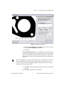
Using the default Rectangle Tool, draw a region of interest (ROI)
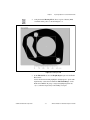
around the entire gasket, as shown in Figure 3-2.
Figure 3-2. Defining the ROI
5.
In the Threshold tab, select the Bright Objects option for the Look
For control.
Notice that the blue shading highlights all bright pixels—pixels with
high intensity values that fall within the Threshold Range—in the
ROI. Vision Builder AI groups contiguous highlighted pixels into
objects, which are depicted by red bounding rectangles.
© National Instruments Corporation
3-5
NI Vision Builder for Automated Inspection Tutorial
Chapter 3
Inspecting Objects for Correct Measurements
6.
Click the Settings tab.
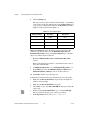
The step locates four objects, which are listed in Table 3-1. Depending
on the location of the user-defined points in the Calibrate Image step
you previously configured, the values for the Size (mm2) may differ
slightly from the values shown in Table 3-1.
Table 3-1. Sizes of Gasket Holes
Object Number
Size (pix2)
Size (mm2)
1
1,807
61.97
2
13,351
457.85
3
40,816
1,399.71
4
1,780
61.04
Object 1 and Object 4 are the small holes of interest in this step. The
following steps describe how to use the Minimum Object Size and
Maximum Object Size controls of the Detect Objects step to eliminate
objects of no interest based on their size.
7.
Enable the Minimum Object Size and Maximum Object Size
controls.
Based on the information in Table 3-1, the small holes have sizes of
61.97 mm2 and 61.04 mm2.
8.
Set Minimum Object Size to 50 and Maximum Object Size to 70.
9.
In the Limits tab, enable the Minimum Number of Objects and
Maximum Number of Objects controls. Set their values to 2.
10. Click OK to add the step to the inspection.
Complete the following instructions to find the large hole in the gasket.
1.
Right-click the Detect Small Holes step in the State Configuration
window, and select Copy.
2.
Right-click the Detect Small Holes step again.
3.
Select Paste. A copy of the Detect Small Holes step is placed after the
original step.
4.
Double-click the Detect Small Holes copy or click the Edit Step
button to launch the property page of the step for editing.
5.
In the Step Name control, enter Detect Large Hole.
NI Vision Builder for Automated Inspection Tutorial
3-6
ni.com
Chapter 3
6.
Inspecting Objects for Correct Measurements
Select the Settings tab.
Based on the information in Table 3-1, the large hole has a size of
1399.71 mm2.
7.
Set Minimum Object Size to 1300 and Maximum Object Size
to 1450.
8.
In the Limits tab, enable the Minimum Number of Objects and
Maximum Number of Objects controls. Set their values to 1.
9.
Click OK to add the step to the inspection.
Measuring Parts of the Gasket
Complete the following instructions to measure the distance from the top
small hole to the large hole to inspect whether the distance meets
specifications.
Note
Vision Builder AI returns the centers of mass for the holes as their locations.
1.
In the Inspection Steps palette, select the Measure Features tab.
2.
Click the Geometry step. The property page for the step opens.
3.
In the Step Name control, enter Check Top Distance.
4.
In the Geometric Feature control, select the Distance measurement.
5.
Select points 1 and 3 by clicking the points in the image or selecting
the points from the Available Points list.
6.
In the Limits tab, enable the Minimum Distance control and set it
to 32. Enable the Maximum Distance control and set it to 35.
7.
Click OK to add the step to the inspection.
Complete the following instructions to measure the distance from the large
hole to the bottom small hole to inspect whether the distance meets
specifications.
1.
Right-click the Top Distance step in the State Configuration window,
and select Copy.
2.
Right-click the Top Distance step again.
3.
Select Paste. A copy of the Top Distance step is placed after the
original step.
4.
Double-click the Top Distance copy or click the Edit Step button to
launch the property page of the step for editing.
5.
In the Step Name control, enter Check Bottom Distance.
© National Instruments Corporation
3-7
NI Vision Builder for Automated Inspection Tutorial
Chapter 3
Inspecting Objects for Correct Measurements
6.
In the Geometric Feature control, select the Distance measurement.
7.
From the Available Points list, select 2 and 3, which correspond to the
bottom small hole and large hole, respectively.
8.
In the Limits tab, enable the Minimum Distance control and set it
to 38. Enable the Maximum Distance control and set it to 40.
9.
Click OK to add the step to the inspection.
Setting the Inspection Status
Complete the following instructions to add a Set Inspection Status step to
determine whether the inspection passes or fails.
1.
In the Inspection Steps palette, select the Use Additional Tools tab.
2.
Click the Set Inspection Status step. The property page for the step
opens.
3.
In the Inspection Status control, select the FAIL if any previous step
fails option.
4.
Click OK to add the step to the inspection.
Testing the Inspection
Test the inspection to make sure it returns the results you expect. Click the
Run Inspection Once button to run the inspection on each of the test
images. Table 3-2 lists the test images, the inspection status to expect for
each image, and an explanation of the status.
Table 3-2. Expected Results for the Gasket Inspection
Image Name
Inspection Status
Explanation
Image 01.jpg
PASS
All steps passed.
Image 02.jpg
PASS
All steps passed.
Image 03.jpg
PASS
All steps passed.
Image 04.jpg
FAIL
The Top Distance step failed because the distance
between the holes is too small.
Image 05.jpg
FAIL
The Detect Small Holes step failed because the
bottom hole is missing. The missing hole also caused
the Bottom Distance step to fail.
NI Vision Builder for Automated Inspection Tutorial
3-8
ni.com
Chapter 3
Inspecting Objects for Correct Measurements
Saving the Inspection
Complete the following instructions to save the example inspection.
1.
Select File»Save or click the Save button on the toolbar.
2.
Navigate to the location where you want to save the inspection.
3.
In the File Name control, enter Tutorial 2.vbai.
4.
Click Save to save the inspection.
Select File»Inspection Properties to add a short description or comments about the
inspection.
Tip
© National Instruments Corporation
3-9
NI Vision Builder for Automated Inspection Tutorial
Inspecting for Multiple Correct
Instances of an Object
4
This chapter introduces the Find Straight Edge, Caliper, and Decision
Making steps. Follow the instructions in this chapter to create an
inspection that measures the distance between the blade connectors of a
fuse and checks the integrity of the fuse conductor regardless of the fuse
position or whether the fuse is inverted.
Launch Vision Builder AI if it is not open. Refer to the Vision Builder AI
Configuration Interface section of Chapter 1, Introduction to Vision Builder AI,
for more information.
Note
Creating a New Inspection
Select File»New. Vision Builder AI opens a new, blank inspection.
Acquiring Inspection Images
For simplicity, this tutorial instructs you to use the Simulate Acquisition
step. However, in your real-world inspection, use one of the other image
acquisition steps to acquire images of the object under inspection.
Complete the following instructions to configure a Simulate Acquisition
step that simulates acquiring images of fuses.
1.
In the Inspection Steps palette, select the Acquire Images tab.
2.
Click the Simulate Acquisition step. The property page for the step
opens.
3.
In the Step Name control, enter Acquire Fuse.
4.
Click the Browse button. The Select an Image File dialog box opens.
5.
Navigate to <Vision Builder AI>\DemoImg\Tutorial 3, where
<Vision Builder AI> is the location where Vision Builder AI is
installed.
6.
© National Instruments Corporation
Select the first image, Image 01.jpg, and click Open.
4-1
NI Vision Builder for Automated Inspection Tutorial
Chapter 4
Inspecting for Multiple Correct Instances of an Object
7.
8.
Make sure the Cycle Through Folder Images control is enabled so
that Vision Builder AI loads a different simulation image from the
folder each time the step is run.
Click OK to add the step to the inspection.
Defining a Feature on which to Base a Coordinate
System
The fuses can appear shifted horizontally and slightly rotated from one
inspection image to another. Complete the following instructions to
configure a Find Straight Edge step that finds the left edge of the fuse so
that regions of interest in subsequent steps can shift with the fuse.
1. In the Inspection Steps palette, select the Locate Features tab.
2. Click the Find Straight Edge step. The property page for the step
opens.
3. In the Step Name control, enter Locate Fuse Left Edge.
4. Draw a region of interest (ROI) across the left edge of the fuse,
as shown in Figure 4-1.
Figure 4-1. Finding a Straight Edge
NI Vision Builder for Automated Inspection Tutorial
4-2
ni.com
Chapter 4
Inspecting for Multiple Correct Instances of an Object
Notice that the ROI contains blue search lines. The step searches along
the search lines for sharp transitions in pixel intensities, which usually
represent object edges. The step fits a straight line through the
individual detected edge points of each search line to determine the left
edge of the fuse.
5.
Click OK to add the step to the inspection.
Setting a Coordinate System
Complete the following instructions to configure a Set Coordinate System
step based on the Find Straight Edge step you configured.
1.
In the Inspection Steps palette, select the Locate Features tab.
2.
Click the Set Coordinate System step. The property page for the step
opens.
3.
In the Main tab, enter Set Coordinate System in the Step Name
control.
4.
In the Settings tab, select Horizontal Motion from the Mode control.
Notice the Origin list. Point 1, the first point of the straight line
detected by the Locate Fuse Left Edge step, is the default origin of the
coordinate system. In this exercise, the location of the origin does not
affect the measurement you need to make. Therefore, use the default
origin.
5.
Click OK to add the step to the inspection.
Measuring the Separation between Connectors
Complete the following instructions to configure a Caliper step that
measures the distance between the blade connectors of the fuse.
1.
In the Inspection Steps palette, select the Measure Features tab.
2.
Click the Caliper step. The property page for the step opens.
3.
In the Main tab, enter Measure Separation in the Step Name
control.
4.
Enable the Reposition Region of Interest control.
© National Instruments Corporation
4-3
NI Vision Builder for Automated Inspection Tutorial
Chapter 4
Inspecting for Multiple Correct Instances of an Object
5.
Draw an ROI across the blade connectors, as shown in Figure 4-2.
Figure 4-2. Measuring the Distance Between Two Edges
6.
In the Settings tab, select the Process named Vertical Min Caliper to
change the direction and orientation of the caliper search lines.
7.
In the Limits tab, enable the Minimum Distance control and set the
value to 150. Enable the Maximum Distance control and set the value
to 160.
8.
Click OK to add the step to the inspection.
NI Vision Builder for Automated Inspection Tutorial
4-4
ni.com
Chapter 4
Inspecting for Multiple Correct Instances of an Object
Inspecting the Fuse Conductor
Complete the following instructions to configure Match Pattern steps that
inspect the integrity of the fuse conductor.
1.
In the Inspection Steps palette, select the Locate Features tab.
2.
Click the Match Pattern step. The NI Vision Template Editor opens.
3.
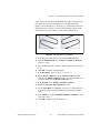
Draw an ROI around the conductor, as shown in Figure 4-3. This
region becomes the pattern matching template.
Figure 4-3. Creating a Template Pattern
4.
Click Next.
5.
Click Finish to accept the template.
6.
On the Main tab, enter Match Conductor 1 in the Step Name
control.
7.
Make sure the Reposition Region of Interest control is enabled.
© National Instruments Corporation
4-5
NI Vision Builder for Automated Inspection Tutorial
Chapter 4
Inspecting for Multiple Correct Instances of an Object
8.
Redraw or decrease the default green ROI so that it surrounds an area
slightly larger than the template, as shown in Figure 4-4.
Figure 4-4. Limiting the Search Region
9.
In the Settings tab, set Number of Matches to Find to 1.
10. Enable the Search for Rotated Patterns control.
11. Set the Angle Range +/– (degrees) control to 10 to enable the step to
locate the best match possible within ±10° of the learned template
angle.
12. In the Limits tab, enable the Minimum Number of Matches control
and set the value to 1.
13. Click OK to add the step to the inspection.
14. Click the Run Inspection Once button twice so that Image 03.jpg
becomes the active image.
The name of the active image is displayed in the Acquire Fuse step in the State
Configuration window.
Note
NI Vision Builder for Automated Inspection Tutorial
4-6
ni.com
Chapter 4
Inspecting for Multiple Correct Instances of an Object
A fuse may be inverted when Vision Builder AI acquires an image of the
fuse. This inversion causes the conductor to look different than the
template, shown in Figure 4-5a. To prevent a good but inverted fuse from
failing inspection, you need to learn a pattern matching template for the
inverted instances of the conductor as well, shown in Figure 4-5b.
a.
b.
Figure 4-5. Valid Templates for the Conductor
15. In the Inspection Steps palette, select the Locate Features tab.
16. Click the Match Pattern step. The Select a template in the image
dialog box opens.
17. Draw an ROI around the conductor, similar to the region you drew in
step 3.
18. Click OK to learn the inverted template.
19. In the Step Name control, enter Match Conductor 2.
20. Set the Region of Interest control to Match Conductor 1. This
configures the Match Conductor 2 step to use the same ROI that you
previously defined for the Match Conductor 1 step.
21. In the Settings tab, set Number of Matches to Find to 1.
22. Enable the Search for Rotated Patterns control.
23. Set the Angle Range +/– (degrees) control to 10 to enable the step to
locate the best match possible within ±10° of the learned template
angle.
24. In the Limits tab, enable the Minimum Number of Matches control
and set the value to 1.
25. Click OK to add the step to the inspection.
© National Instruments Corporation
4-7
NI Vision Builder for Automated Inspection Tutorial
Chapter 4
Inspecting for Multiple Correct Instances of an Object
Making Logical PASS/FAIL Decisions
In the previous lessons, the inspection would fail if any of the steps in the
inspection failed. In this lesson, because the conductor under inspection can
match only one of the patterns you specified, one of the Match Pattern
steps always fails. If you were to set the Inspection Status to fail if any of
the steps in the inspection fail, the entire inspection will always fail because
one of the Match Pattern steps always fails.
Using the Logic Calculator step, you can create a Boolean result that is
based on the results of the previous inspection steps. The Set Inspection
Status step can use this Boolean result to determine the Inspection Status.
Complete the following instructions to configure a Logic Calculator step
that causes the inspection to pass when the conductor matches either the
template in Match Conductor 1 or Match Conductor 2, and when the
Measure Separation step passes.
1.
In the Inspection Steps palette, select the Use Additional Tools tab.
2.
Click the Logic Calculator step. The property page opens in the Main
window.
3.
In the Step Name control, enter Decide Pass/Fail.
4.
In the First Operand frame, set Source to Measure Separation.
Set Measure to Step Status.
Current Value displays the value of the measurement based on the
current image.
5.
Make sure Second Operand is set to Constant, and Constant is set
to True.
6.
Click Add to add this expression to the Expression table.
7.
In the First Operand frame, set Source to Match Conductor 1.
Set Measure to Step Status.
8.
Make sure Second Operand is set to Constant, and Constant is set
to True.
9.
Click Add to add this expression to the Expression table.
Notice the default binary operator AND in the last column of the
Expression table.
10. In the First Operand frame, set Source to Match Conductor 2.
Set Measure to Step Status.
11. Make sure Second Operand is set to Constant and Constant is set
to True.
NI Vision Builder for Automated Inspection Tutorial
4-8
ni.com
Chapter 4
Inspecting for Multiple Correct Instances of an Object
12. Click Add to add this expression to the Expression table.
13. Select the second expression in the Expression table, and click
AND/OR to change the binary operator to OR.
14. Hold down the <Shift> key, and select the second and third expressions
in the Expression table.
15. Click ( ) to group the expressions.
The Logic Calculator property page should resemble Figure 4-6.
Figure 4-6. Logic Calculator Property Page
16. Click OK to add the step to the inspection.
© National Instruments Corporation
4-9
NI Vision Builder for Automated Inspection Tutorial
Chapter 4
Inspecting for Multiple Correct Instances of an Object
Setting the Inspection Status
Complete the following instructions to configure Vision Builder AI to pass
the inspection when the Logic Calculator step passes, regardless of the
results of individual steps in the inspection.
1.
In the Inspection Steps palette, select the Use Additional Tools tab.
2.
Click the Set Inspection Status step. The property page for the step
opens.
3.
In the Step Name control enter Set Inspection Status.
4.
In the Inspection Status control select the Equals specified
measurement option, and select Decide Pass/Fail - Step Status for
the value.
5.
Make sure the Update Number of Parts Inspected control is enabled.
6.
Click OK to add the step to the inspection.
Testing the Inspection
Test the inspection to make sure it returns the results you expect. Click the
Run Inspection Once button to test the remaining images. Table 4-1 lists
the test images, the inspection status to expect for each image, and an
explanation of the status.
Table 4-1. Expected Results for the Fuse Inspection
Image Name
Inspection Status
Explanation
Image 01.jpg
PASS
All steps pass but one Match Pattern step.
Image 02.jpg
PASS
All steps pass but one Match Pattern step.
Image 03.jpg
PASS
All steps pass but one Match Pattern step.
Image 04.jpg
PASS
All steps pass but one Match Pattern step.
Image 05.jpg
PASS
All steps pass but one Match Pattern step.
Image 06.jpg
FAIL
The Measure Separation step fails because
the blade connectors are too close together.
Image 07.jpg
FAIL
Both Match Pattern steps fail because the
conductor is blown.
Image 08.jpg
FAIL
Both Match Pattern steps fail because the
conductor is melted.
NI Vision Builder for Automated Inspection Tutorial
4-10
ni.com
Chapter 4
Inspecting for Multiple Correct Instances of an Object
Saving the Inspection
Complete the following instructions to save the example inspection.
1.
Select File»Save or click the Save button on the toolbar.
2.
Navigate to the location where you want to save the inspection.
3.
In the File Name control, enter Tutorial 3.vbai.
4.
Click Save to save the inspection.
Select File»Inspection Properties to add a short description or comments about the
inspection.
Tip
© National Instruments Corporation
4-11
NI Vision Builder for Automated Inspection Tutorial
Inspecting an Object that Spans
Two Image Frames
5
This chapter introduces the Select Image and Calculator steps.
Assume that you need to measure the width of a wide wooden plank with
high accuracy. The only cameras available for the application have low
pixel resolutions.
To measure the width of a plank, you need to locate its left and right edges.
If you were to set up the imaging system so both edges of a plank fit within
an available camera’s field of view, the resulting image detail would be too
low to yield accurate measurements. Because the required image detail
exceeds the pixel resolution capability of a single camera, two cameras per
plank are needed—one camera to acquire an image of the left edge and one
camera to acquire an image of the right edge.
Follow the instructions in this chapter to create an inspection that measures
the width of a wooden plank that spans two images.
Launch Vision Builder AI if it is not open. Refer to the Vision Builder AI
Configuration Interface section of Chapter 1, Introduction to Vision Builder AI,
for more information.
Note
Creating a New Inspection
Select File»New. Vision Builder AI opens a new, blank inspection.
© National Instruments Corporation
5-1
NI Vision Builder for Automated Inspection Tutorial
Chapter 5
Inspecting an Object that Spans Two Image Frames
Acquiring Inspection Images from Two Cameras
For simplicity, this tutorial instructs you to use the Simulate Acquisition
step. However, in your real-world inspection, use one of the other image
acquisition steps to acquire images of the object under inspection.
Acquiring and Calibrating the Image of the Left Edge
Complete the following instructions to configure Simulate Acquisition
steps that simulate acquiring an image of the left section of the wooden
plank and calibrating the image.
1.
In the Inspection Steps palette, select the Acquire Images tab.
2.
Click the Simulate Acquisition step. The property page for the step
opens.
3.
In the Step Name control, enter Acquire Plank (Left).
4.
Click the Browse button. The Select an Image File dialog box opens.
5.
Navigate to <Vision Builder AI>\DemoImg\Tutorial 4 Left,
where <Vision Builder AI> is the location where Vision Builder
AI is installed.
6.
Select the first image, Image 01.jpg, and click Open.
7.
Make sure the Cycle Through Folder Images control is enabled so
that Vision Builder AI loads a different simulation image from the
folder each time the step is run.
8.
Click the Calibration tab.
9.
Click Create Calibration to launch the calibration wizard.
10. In the Calibration Name control, enter Plank Calibration
(Left).
11. Click Next.
For this example, assume that the camera that acquired the inspection
images is perpendicular to the image plane and lens distortion is negligible.
Based on these assumptions, you can use Simple Calibration to calibrate
your images. Simple Calibration transforms a pixel coordinate to a
real-world coordinate through scaling in the x (horizontal) and y (vertical)
directions.
12. Select the Simple Calibration option, and click Next.
13. Make sure Use Current Image is selected, and click Next.
14. Make sure Pixel Type is set to Square because the camera that
acquired the images for this exercise has square pixels.
NI Vision Builder for Automated Inspection Tutorial
5-2
ni.com
Chapter 5
Inspecting an Object that Spans Two Image Frames
15. Click Next.
16. In the Specify the Pixel Ratio step, carefully click the 1 cm and 5 cm
markings on the ruler at the bottom of the image, as shown in
Figure 5-1.
You may need to use the zoom buttons below the image to accurately click the ruler
markings. After zooming in, scroll down to see the ruler at the bottom of the image.
Tip
Figure 5-1. Defining the Pixel to Real-World Ratio
17. In the Correspondence Image - Real World control, enter 4 for the
value, and select centimeter for the Unit.
18. Click Next.
© National Instruments Corporation
5-3
NI Vision Builder for Automated Inspection Tutorial
Chapter 5
Inspecting an Object that Spans Two Image Frames
19. In the Set Calibration Axis step, click the 1 cm marking to define it as
the origin of the calibration axis. Draw a line horizontally and to the
right along the edge of the ruler to define the angle of the calibration
axis, as shown in Figure 5-2.
Figure 5-2. Defining the Origin and Angle of the Calibration Axis
20. Set the Axis Reference control to Direct.
21. Click OK to learn the calibration information and exit the calibration
wizard.
22. Click OK to add the step to the inspection.
NI Vision Builder for Automated Inspection Tutorial
5-4
ni.com
Chapter 5
Inspecting an Object that Spans Two Image Frames
Acquiring and Calibrating the Image of the Right Edge
This section simulates acquiring an image of the right section of the
wooden plank. Because the simulated acquisition represents a second
camera, you cannot reuse the calibration that you created for the first
camera.
Complete the following instructions to configure Simulate Acquisition
steps that simulate acquiring an image of the right section of the wooden
plank and calibrating the image.
1.
In the Inspection Steps palette, select the Acquire Images tab.
2.
Click the Simulate Acquisition step. The property page for the step
opens.
3.
In the Step Name control, enter Acquire Plank (Right).
4.
Click the Browse button. The Select an Image File dialog box opens.
5.
Navigate to <Vision Builder AI>\DemoImg\Tutorial 4
Right, where <Vision Builder AI> is the location where Vision
Builder AI is installed.
6.
Select the first image, Image 01.jpg, and click Open.
7.
Make sure the Cycle Through Folder Images control is enabled so
that Vision Builder AI loads a different simulation image from the
folder each time the step is run.
8.
Click the Calibration tab.
9.
Click Create Calibration to launch the calibration wizard.
10. In the Calibration Name control, enter Plank Calibration
(Right).
11. Click Next.
Again, assume that the camera that acquired the inspection images is
perpendicular to the image plane and lens distortion is negligible.
12. Select the Simple Calibration option, and click Next.
13. Make sure Use Current Image is selected, and click Next.
14. Make sure Pixel Type is set to Square because the camera that
acquired the images for this exercise has square pixels.
15. Click Next.
© National Instruments Corporation
5-5
NI Vision Builder for Automated Inspection Tutorial
Chapter 5
Inspecting an Object that Spans Two Image Frames
16. In the Specify the Pixel Ratio step, carefully click the 38 cm and
42 cm markings on the ruler at the bottom of the image, as shown in
Figure 5-3.
You may need to use the zoom buttons below the image to accurately click the ruler
markings. After zooming in, scroll down to see the ruler at the bottom of the image.
Tip
Figure 5-3. Defining the Pixel to Real-World Ratio
17. In the Correspondence Image - Real World control, enter 4 for the
value, and select centimeter for the Unit.
18. Click Next.
NI Vision Builder for Automated Inspection Tutorial
5-6
ni.com
Chapter 5
Inspecting an Object that Spans Two Image Frames
19. In the Set Calibration Axis step, click the 38 cm marking to define it
as the origin of the calibration axis. Draw a line horizontally and to the
right along the edge of the ruler to define the angle of the calibration
axis, as shown in Figure 5-4.
Figure 5-4. Defining the Origin and Angle of the Calibration Axis
20. Set the Axis Reference control to Direct.
21. Click OK to learn the calibration information and exit the calibration
wizard.
22. Click OK to add the step to the inspection.
Locating the Right Edge of the Part
Complete the following instructions to configure a Find Edges step that
locates the right edge of the part.
1.
In the Inspection Steps palette, select the Locate Features tab.
2.
Click the Find Edges step. The property page for the step opens.
3.
In the Step Name control, enter Find Right Edge.
© National Instruments Corporation
5-7
NI Vision Builder for Automated Inspection Tutorial
Chapter 5
Inspecting an Object that Spans Two Image Frames
4.
Draw a line across the right edge of the part going from right to left, as
shown in Figure 5-5.
Pressing the <Shift> key while drawing a line constrains the line tool to only draw
horizontal or vertical lines.
Tip
5.
Click the Settings tab.
6.
In the Look for control, select First Edge.
7.
In the Edge Polarity control, select Bright to Dark Only.
Find Right Edge
Figure 5-5. Finding the Right Edge of the Plank
Notice the red square on the search line. The step searches along the
search line for a sharp transition in pixel intensities, which usually
represents an object edge. The red square marks the location of the
right edge of the part.
8.
Click OK to add the step to the inspection.
NI Vision Builder for Automated Inspection Tutorial
5-8
ni.com
Chapter 5
Inspecting an Object that Spans Two Image Frames
Switching Images
Now that you have configured the inspection to locate the right edge of the
wooden plank, you need to switch to the image of the left side of the plank.
Complete the following instructions to configure a Select Image step that
makes the image of the left side of the plank active for processing.
1.
In the Inspection Steps palette, select the Acquire Images tab.
2.
Click the Select Image step. The property page for the step opens.
3.
In the Step Name control, enter Switch to Left Side.
4.
In the Image Selection list, select Acquire Plank (Left). The image
of the left side of the part appears in the Main window.
5.
Click OK to add the step to the inspection.
Locating the Left Edge of the Part
Complete the following instructions to configure a Find Edges step that
locates the left edge of the part.
1.
In the Inspection Steps palette, select the Locate Features tab.
2.
Click the Find Edges step. The property page for the step opens.
3.
In the Step Name control, enter Find Left Edge.
4.
Hold down the <Shift> key and draw a line across the left edge of the
part going from left to right, as shown in Figure 5-6.
5.
Click the Settings tab.
6.
In the Look for control, select First Edge.
7.
In the Edge Polarity control, select Bright to Dark Only.
© National Instruments Corporation
5-9
NI Vision Builder for Automated Inspection Tutorial
Chapter 5
Inspecting an Object that Spans Two Image Frames
Find Left Edge
Figure 5-6. Finding the Left Edge of the Plank
The step searches along the search line and marks the location of the
left edge with a red square.
8.
Click OK to add the step to the inspection.
NI Vision Builder for Automated Inspection Tutorial
5-10
ni.com
Chapter 5
Inspecting an Object that Spans Two Image Frames
Calculating the Width of the Part
Now that you have located the right edge of the part in one image and
the left edge of the part in another image, you need to combine the
measurements from the two images to determine the width of the part. Use
the Calculator step to combine the two measurements and compute the
width.
Refer to the following equations as you configure the step.
where
Right (LC) = Right (RC) + (Origin R – Origin L)
(5-1)
Part Width = Right (LC) – Left (LC)
(5-2)
Right (LC) = The x position of the right edge in the calibration
axis of the left edge.
Right (RC) = The x position of the right edge in the calibration
axis of the right edge. This corresponds to the calibrated
x position result of the Find Right Edge step.
Origin R = The x position of the origin in the calibration axis of
the right edge.
Origin L = The x position of the origin in the calibration axis of
the left edge.
Left (LC) = The x position of the left edge in the calibration axis
of the left edge. This corresponds to the calibrated x position
result of the Find Left Edge step.
Setting Calculator Step Inputs and Outputs
Complete the following instructions to configure a Calculator step to
select the input measurements from the previous Find Right Edge and
Find Left Edge steps, and create output results for the calculated values.
1.
In the Inspection Steps palette, select the Use Additional Tools tab.
2.
Click the Calculator step. The Calculator Setup Wizard opens.
3.
Click Next to proceed with the wizard.
Notice the Input Measurements list. The list contains all of the
measurable data from each of the previous steps in the inspection.
© National Instruments Corporation
5-11
NI Vision Builder for Automated Inspection Tutorial
Chapter 5
Inspecting an Object that Spans Two Image Frames
4.
Select the following measurements from the Input Measurements
list:
•
Find Right Edge»Edge [1].X Position (Calibrated)
•
Find Left Edge»Edge [1].X Position (Calibrated)
5.
Click Next.
6.
Click Add New Output Result. A new output appears in the Output
Results list.
7.
In the Name control, enter Part Width. This output will contain the
results of Equation 5-2.
8.
Make sure Type is set to Numeric.
9.
Click Add New Output Result again.
10. In the Name control, enter Right (LC). This output will contain the
results of Equation 5-1.
11. Make sure Type is set to Numeric.
12. Click Finish to close the Calculator Setup Wizard.
The Main window now displays a diagram with the measurement inputs
and result outputs you specified in the Calculator Setup Wizard, as shown
in Figure 5-7. The diagram also contains a default Boolean result named
Step Result. You can connect the result of a computation to Step Result,
which changes the status of the Calculator step to the result of the
computation. Refer to the Making Logical PASS/FAIL Decisions with the
Calculator Step section of this chapter for more information about Step
Result.
Figure 5-7. Calculator Diagram Elements
Notice that the inputs and outputs are framed with color and have codes at the
bottom of their frames. These colors and codes visually group inputs and
outputs into their respective data types—numerics, Booleans, or strings.
NI Vision Builder for Automated Inspection Tutorial
5-12
ni.com
Chapter 5
Inspecting an Object that Spans Two Image Frames
13. To simplify the process of connecting the diagram elements later in
this chapter, arrange the elements into the configuration shown in
Figure 5-8 by dragging them to their new positions.
Figure 5-8. Arranging Diagram Elements
Adding Operators and Constants
Earlier in this chapter, you used the Calibration Wizard to set calibration
axis origins for the right and left sides of the part. These origins are the only
elements of Equations 5-1 and 5-2 not yet represented in the Calculator
diagram: (Origin R and Origin L).
In step 19 of the Acquiring and Calibrating the Image of the Right Edge
section of this chapter, you set the origin of the right side to the 38 cm
marking of the imaged ruler. In step 19 of the Acquiring and Calibrating
the Image of the Left Edge section of this chapter, you set the origin of the
left side to the 1 cm marking of the imaged ruler. Therefore,
(Origin R – Origin L) = 38 – 1 = 37.
The distance between the calibration axis origins is a constant value. Add a
constant with the value 37 to the Calculator diagram.
1.
In the Functions palette, click Numeric.
2.
Click the Num Const operator. Click inside the Calculator diagram
below the Find Right Edge - Edge [1].X Position (Calibrated) input
measurement to place the numeric constant on the Calculator diagram.
3.
Double-click the numeric constant and type 37 to set the value of the
constant.
© National Instruments Corporation
5-13
NI Vision Builder for Automated Inspection Tutorial
Chapter 5
Inspecting an Object that Spans Two Image Frames
4.
Click the Add operator in the Functions palette. Click inside the
Calculator diagram to the right of the Find Right Edge - Edge [1].X
Position (Calibrated) input measurement.
Place the Add operator close enough to the Find Right Edge - Edge [1].X Position
(Calibrated) input so that the Calculator step automatically connects the two elements
with a wire.
Tip
5.
Click the Show Help Window button on the Main tab of the
Calculator step to launch the Help window, or click the Help button
in the Calculator diagram toolbar. When you move your cursor over
certain elements within the Calculator diagram, information about that
item shows in the Help window.
6.
Place your cursor over the Add operator. Notice in the Help window
that the operator has an x input terminal, y input terminal, and
x+y output terminal.
7.
Click the Subtract operator in the Functions palette. Click inside the
Calculator diagram to the right of the Find Left Edge - Edge [1].X
Position (Calibrated) input measurement.
Your Calculator diagram should look similar to the diagram shown in
Figure 5-9.
Figure 5-9. Unconnected Diagram Elements
Connecting the Equation Elements
Complete the following instructions to wire the diagram elements together
such that they form Equation 5-1: Right (LC) = Right (RC) + (37).
1.
Place your cursor on the small, triangular terminal located on the right
side of the numeric constant. The cursor changes into a Wiring tool.
NI Vision Builder for Automated Inspection Tutorial
5-14
ni.com
Chapter 5
Inspecting an Object that Spans Two Image Frames
2.
Use the Wiring tool to click the terminal and release the mouse. As you
move the cursor across the Calculator diagram, the Calculator step
draws a wire between the terminal and the Wiring tool as though the
wire were unwinding from a spool.
3.
Without holding down the mouse button, move the cursor to the y input
terminal of the Add operator. The y input terminal blinks. Use the
Wiring tool to click the y input terminal and complete the connection.
4.
Click the output terminal of the Add operator, and connect it to the
input terminal of Right (LC).
If you do not terminate a wire correctly, the wire is broken and appears as a dashed
black line with a red X in the middle. Click Remove Broken Wires in the Main tab to
remove broken wires.
Tip
Complete the following instructions to wire the diagram elements together
such that they form Equation 5-2: Part Width = Right (LC) – Left (LC).
1.
Place the cursor on the wire that connects the Add operator to
Right (LC). The cursor changes into the Wiring tool.
2.
Click the wire, and connect it to the x input terminal of the Subtract
operator.
3.
Click the Find Left Edge - Edge [1].X Position (Calibrated) output
terminal, and connect it to the y input terminal of the Subtract
operator.
4.
Click the output terminal of the Subtract operator, and connect it to
the input terminal of Part Width.
Your connected Calculator diagram should look similar to the diagram
shown in Figure 5-10.
Figure 5-10. Connected Elements of Calculator Diagram
© National Instruments Corporation
5-15
NI Vision Builder for Automated Inspection Tutorial
Chapter 5
Inspecting an Object that Spans Two Image Frames
5.
In the Calculator step property page, click the Measurements tab.
6.
Click Compute Results to see the results of the calculation thus far.
Making Logical PASS/FAIL Decisions with the Calculator Step
Now that you have a created a diagram to measure the width of the part,
you need a way to verify that the width meets manufacturing specifications.
Complete the following instructions to add diagram elements that compare
the measured width to minimum and maximum width tolerances and
decide whether the plank passes inspection.
1.
Click the up arrow in the Functions palette to return to the main palette.
2.
Select the Comparison palette.
3.
Click the Less? operator in the Comparison palette. Click inside the
Calculator diagram below Part Width.
4.
Connect the wire between Subtract and Part Width to the x input of
the Less? operator.
5.
Click the up arrow in the Functions palette to return to the main palette.
6.
Select the Numeric palette.
7.
Click the Num Const operator in the Numeric palette.
8.
Click close enough to the y input of Less? to automatically wire the
numeric constant and y input together.
9.
Type 40.5 to set the maximum width a plank can be to pass the
inspection.
10. Click the up arrow in the Functions palette to return to the main palette.
11. Select the Comparison palette.
12. Click the Greater? operator. Click inside the Calculator diagram
below the Less? operator.
13. Connect the wire between Subtract and Part Width to the x input of
the Greater? operator.
14. Click the up arrow in the Functions palette to return to the main palette.
15. Select the Numeric palette.
16. Click the Num Const operator.
17. Click close enough to the y input of Greater? to automatically wire the
numeric constant and y input together.
18. Type 39.5 to set the minimum width a plank can be to pass the
inspection.
19. Click the up arrow in the Functions palette to return to the main palette.
NI Vision Builder for Automated Inspection Tutorial
5-16
ni.com
Chapter 5
Inspecting an Object that Spans Two Image Frames
20. Select the Boolean palette.
21. Click the And operator. Click close enough to the left side of Step
Result to wire the two elements together.
22. Connect the Less? output to the x input of And.
23. Connect the Greater? output to the y input of And.
Your completed Calculator diagram should look similar to the diagram
shown in Figure 5-11.
Figure 5-11. Calculator Diagram with Decision-Making Abilities
24. In the Calculator step property page, click the Limits tab.
25. Enable the Step Result is True checkbox.
26. Click OK to add the step to the inspection.
Setting the Inspection Status
Complete the following instructions to add a Set Inspection Status step to
determine whether the inspection passes or fails.
1.
In the Inspection Steps palette, select the Use Additional Tools tab.
2.
Click the Set Inspection Status step. The property page for the step
opens.
3.
In the Inspection Status control, Select the FAIL if any previous
step fails option.
4.
Click OK to add the step to the inspection.
© National Instruments Corporation
5-17
NI Vision Builder for Automated Inspection Tutorial
Chapter 5
Inspecting an Object that Spans Two Image Frames
Testing the Inspection
Test the inspection to make sure it returns the results you expect. Click the
Run Inspection Once button to test the remaining images. Table 5-1 lists
the test images, the inspection status to expect for each image, and an
explanation of the status.
Note Results may vary slightly based on the accuracy of the calibration and the edge
detection location.
Table 5-1. Expected Results for the Plank Inspection
Image Name
Part Width
Inspection Status
Image 01.jpg
40.00 cm
PASS
Image 02.jpg
40.16 cm
PASS
Image 03.jpg
40.28 cm
PASS
Image 04.jpg
39.27 cm (too short)
FAIL
Image 05.jpg
40.90 cm (too long)
FAIL
Saving the Inspection
Complete the following instructions to save the example inspection.
1.
Select File»Save or click the Save button on the toolbar.
2.
Navigate to the location where you want to save the inspection.
3.
In the File Name control, enter Tutorial 4.vbai.
4.
Click Save to save the inspection.
Select File»Inspection Properties to add a short description or comments about the
inspection.
Tip
NI Vision Builder for Automated Inspection Tutorial
5-18
ni.com
Branching and Decision Making
6
This chapter introduces the inspection state diagram and the Custom
Overlay step. Follow the instructions in this chapter to create an inspection
that checks the image for the presence of a spray bottle and, if a bottle is
present, transitions to another state to determine if the bottle has a cap. If
there is no spray bottle present in the image, the inspection moves on to the
next image.
Launch Vision Builder AI if it is not open. Refer to the Vision Builder AI
Configuration Interface section of Chapter 1, Introduction to Vision Builder AI,
for more information.
Note
Creating a New Inspection
Select File»New to load a new, blank Vision Builder AI inspection.
Creating the Inspection State Diagram
The configurable process model in Vision Builder AI is represented by a
state diagram. Complete the following instructions to create a state diagram
to define the inspection.
1.
Click the Toggle Main Window View button on the toolbar to bring
the state diagram to the Main window.
Figure 6-1. Default Inspection State Diagram
© National Instruments Corporation
6-1
NI Vision Builder for Automated Inspection Tutorial
Chapter 6
Branching and Decision Making
2.
Double-click the Inspect state to launch the Edit State Name dialog
box.
3.
In the State Name control, enter Check Part Presence, and
click OK.
4.
Right-click an open area on the state diagram and select Create New
State to add a new state to the inspection, as shown in Figure 6-2. The
Edit State Name dialog box opens.
Figure 6-2. Creating a New Inspection State
5.
In the State Name control, enter Inspect Part.
NI Vision Builder for Automated Inspection Tutorial
6-2
ni.com
Chapter 6
6.
Branching and Decision Making
Create two more states named Fail Part and Pass Part. The state
diagram should now resemble the state diagram shown in Figure 6-3.
Figure 6-3. Adding New States to the Inspection
Next, you will create transitions between the various inspection states.
Notice that every state has a default transition. You can also create
additional transitions between states based on measurement results or
variable values.
The default transition occurs if the transition requirements for other possible
transitions are not met.
Note
7.
Click the arrow of the Check Part Presence default transition and drag
it back to the Check Part Presence state. This creates a loop that will
run the steps in the Check Part Presence State until a part is detected.
8.
Click the End point and drag it to the bottom of the state diagram.
9.
Click the Inspect Part default transition and drag it to the Fail Part
state.
10. Click the Fail Part default transition and drag it to the End point.
11. Click the Pass Part default transition and drag it to the End point.
© National Instruments Corporation
6-3
NI Vision Builder for Automated Inspection Tutorial
Chapter 6
Branching and Decision Making
The state diagram should now resemble the state diagram shown in
Figure 6-4.
Figure 6-4. Configuring the Default Transitions
12. Right-click the Check Part Presence state and select Create New
Transition.
13. Click the Inspect Part state to create a transition between the Check
Part Presence and Inspect Parts states, as shown in Figure 6-5.
Figure 6-5. Creating a New Transition
You can change the shape of the transition by dragging the anchor
point at the center of the transition. You can move the location of the
transition label by clicking the label and dragging it to the new
location.
NI Vision Builder for Automated Inspection Tutorial
6-4
ni.com
Chapter 6
Branching and Decision Making
When drawing a transition, click once on the state diagram to set the anchor point for
the transition. The anchor point allows you to draw an arc instead of a straight line to
represent the transition.
Tip
14. Double-click the transition to launch the Edit Transition dialog box,
which is used to configure the transition.
15. In the Transition Name control, enter Part Detected, and
click OK.
16. Create another transition named Part OK between the Inspect Part
and Pass Part states.
The state diagram should now resemble the state diagram shown in
Figure 6-6.
Figure 6-6. Completed State Diagram for the Inspection
You can remove a state or transition from the inspection by selecting the object you
want to remove and pressing the <Delete> key.
Note
Note
You cannot rename or remove the default transition of a state.
Each state in an inspection is intended to contain a separate set of inspection
steps. To access the functions in a state, click the state in the state diagram.
The currently selected state is highlighted in blue on the state diagram.
© National Instruments Corporation
6-5
NI Vision Builder for Automated Inspection Tutorial
Chapter 6
Branching and Decision Making
Acquiring Inspection Images
For simplicity, this tutorial instructs you to use the Simulate Acquisition
step. However, in your real-world inspection, use one of the other image
acquisition steps to acquire images of the object under inspection.
Complete the following instructions to configure a Simulate Acquisition
step that simulates acquiring images of spray bottles.
1.
On the state diagram, click the Check Part Presence state.
2.
In the Inspection Steps palette, select the Acquire Images tab.
3.
Click the Simulate Acquisition step. The property page for the step
opens.
When the property page for an inspection step opens, if the state diagram is
displayed in the Main window, the state diagram switches from the Main window to the
Overview window to allow you to use the current inspection image to configure the step.
Note
4.
In the Step Name control, enter Acquire Image.
5.
Click the Browse button. The Select an Image File dialog box opens.
6.
Navigate to <Vision Builder AI>\DemoImg\Tutorial 5, where
<Vision Builder AI> is the location where Vision Builder AI is
installed.
7.
Select an image containing the entire spray bottle, such as
Image 00480.jpg, and click Open.
8.
Make sure the Cycle Through Folder Images control is enabled so
that Vision Builder AI loads a different simulation image from the
folder each time the step is run.
9.
Click OK to add the step to the inspection.
Checking for a Spray Bottle in the Image
Complete the following instructions to configure a Match Pattern step to
check for the presence of a spray bottle in the image.
1.
In the Inspection Steps palette, select the Locate Features tab.
2.
Click the Match Pattern step. The NI Vision Template Editor opens.
3.
Draw a region of interest (ROI) around the bottom left edge of the
bottle. This region becomes the pattern matching template.
4.
Click Next.
NI Vision Builder for Automated Inspection Tutorial
6-6
ni.com
Chapter 6
Branching and Decision Making
5.
Click Finish to accept the template.
6.
On the Main tab, enter Locate Bottle in the Step Name control.
7.
Adjust the default green ROI so that it only surrounds the area of the
image that could contain the bottom left edge of a spray bottle,
as shown in Figure 6-7.
Figure 6-7. Adjusting the Search Region
8.
On the Settings tab, set the Number of Matches to Find control to 1.
9.
On the Limits tab, enable the Minimum Number of Matches control,
and set the value to 1.
10. Click OK to add the step to the inspection.
© National Instruments Corporation
6-7
NI Vision Builder for Automated Inspection Tutorial
Chapter 6
Branching and Decision Making
Checking for the Cap Using the Caliper
You can check for the presence of the cap on a spray bottle by using the
Caliper step to find two edges where the cap is supposed to be and
measuring the distance between them. Complete the following instructions
to configure a Caliper step to check for the presence of the spray bottle cap.
1.
In the Overview window, click the Inspect Part state on the state
diagram.
2.
In the Inspection Steps palette, select the Measure Features tab.
3.
Click the Caliper step. The property page for the step opens.
4.
In the Step Name control, enter Check Cap Presence.
5.
Draw an ROI around the area in the image where a cap should appear,
as shown in Figure 6-8.
Figure 6-8. Checking for Cap Presence
NI Vision Builder for Automated Inspection Tutorial
6-8
ni.com
Chapter 6
Branching and Decision Making
6.
On the Settings tab, select the Process named Horizontal Max
Caliper to change the direction and orientation of the caliper search
lines.
7.
Set the Gap control to 10, Edge Strength to 40, and Smoothing to 12
to ensure that the step correctly detects the edges of the cap.
8.
On the Limits tab, enable the Minimum Distance control, and set the
value to 140.
9.
Enable the Maximum Distance control, and set the value to 160.
10. Click OK to add the step to the inspection.
Setting the Inspection Status
Complete the following instructions to add a Set Inspection Status step to
determine whether the inspection passes or fails.
1.
In the Inspection Steps palette, click the Use Additional Tools tab.
2.
Click the Set Inspection Status step. The property page for the step
opens.
3.
In the Inspection Status control, select the FAIL if any previous step
fails option.
4.
Click OK to add the step to the inspection.
Creating Custom Overlays for Inspection
Use the Custom Overlay step to create custom overlays that display
whether the inspection passed or failed.
Complete the following steps to create an overlay to display when the
inspection fails.
1.
In the Overview window, click the Fail Part state on the state diagram.
2.
In the Inspection Steps palette, select the Use Additional Tools tab.
3.
Click the Custom Overlay step. The property page for the step opens.
4.
In the Step Name control, enter Overlay Results.
5.
On the Custom Overlay tab, select the Text tool and click a point in
the image near the bottom of the spray nozzle of the bottle.
6.
In the Text Control, enter Missing Cap!.
7.
Click the Text Properties button. The Text Properties dialog box
opens.
© National Instruments Corporation
6-9
NI Vision Builder for Automated Inspection Tutorial
Chapter 6
Branching and Decision Making
8.
In the Desired Font control, select User-Specified Font.
9.
Specify a Font Name and Size to use for the overlay.
10. In the Horizontal Alignment control, select Center. This centers the
text around the point you selected using the Text tool.
11. Click OK to save the Text Properties settings and close the dialog box.
12. Click OK to add the step to the inspection.
Next, you need to create an overlay to display if the inspection passes.
Complete the following steps to create an overlay to display when the
inspection passes.
1.
In the Overview window, click the Pass Part state on the state
diagram.
2.
In the Inspection Steps palette, select the Use Additional Tools tab.
3.
Click the Custom Overlay step. The property page for the step opens.
4.
In the Step Name control, enter Overlay Results.
5.
On the Custom Overlay tab, select the Rectangle tool and draw a
rectangle in the upper-left corner of the image.
6.
Click the Stroke control, and select black.
7.
Click the Fill control, and select a bright green color.
8.
On the Custom Overlay tab, select the Text tool, and click a point just
below the center of the rectangle overlay.
9.
In the Text control, enter Part OK.
10. Click the Text color control, and select black.
11. Click the Text Properties button. The Text Properties dialog box
appears.
12. In the Desired Font control, select User-Specified Font.
13. Specify a Font Name and Size to use for the overlay.
14. In the Horizontal Alignment control, select Center.
15. Click OK to save the Text Properties settings and close the dialog box.
16. Click OK to add the step to the inspection.
NI Vision Builder for Automated Inspection Tutorial
6-10
ni.com
Chapter 6
Branching and Decision Making
Figure 6-9 shows the overlays for both Pass and Fail images.
Figure 6-9. Creating Custom Overlays for Images that Pass and Fail
Configuring State Transitions
Once you have configured all of the states in the inspection and created
transitions between the states, you need to define the conditions that trigger
a transition between inspection states. Complete the following instructions
to define the transitions between inspection states.
1.
Click the Toggle Main Window View button to display the state
diagram in the Main window.
2.
Double-click the Part Detected transition to launch the Edit
Transition dialog box, which is used to configure the transition.
© National Instruments Corporation
6-11
NI Vision Builder for Automated Inspection Tutorial
Chapter 6
Branching and Decision Making
3.
In the Edit Transition dialog box, modify the controls to transition
when Locate Bottle - # Matches is Equal to 1, as shown in
Figure 6-10.
Figure 6-10. Configuring the Part Detected Transition
4.
Click OK to close the Edit Transition dialog box.
5.
Double-click the Part OK transition. The Edit Transition dialog box
opens.
NI Vision Builder for Automated Inspection Tutorial
6-12
ni.com
Chapter 6
6.
Branching and Decision Making
In the Edit Transition dialog box, modify the controls to transition
when Check Cap Presence - Step Status is Pass, as shown in
Figure 6-11.
Figure 6-11. Configuring the Part OK Transition
7.
Click OK to close the Edit Transition dialog box.
Testing the Inspection
Test the images in the Tutorial 5 folder to make sure the inspection
returns the correct results. Click the Run Inspection Once button to test
the remaining images. Table 6-1 displays the expected results for each
image.
Table 6-1. Expected Results for the State Diagram Branching Inspection
Image Name
© National Instruments Corporation
Inspection Status
Explanation
Image 00480.jpg
PASS
Cap is present.
Image 01710.jpg
PASS
Cap is present
Image 03450.jpg
FAIL
Cap is missing.
Image 04200.jpg
PASS
Cap is present.
6-13
NI Vision Builder for Automated Inspection Tutorial
Chapter 6
Branching and Decision Making
Saving the Inspection
Complete the following instructions to save the example inspection.
1.
Select File»Save or click the Save button on the toolbar.
2.
Navigate to the location where you want to save the inspection.
3.
In the File Name control, enter Tutorial 5.vbai.
4.
Click Save to save the inspection.
Select File»Inspection Properties to add a short description or comments about the
inspection.
Tip
NI Vision Builder for Automated Inspection Tutorial
6-14
ni.com
7
Looping and Variables
This chapter uses the inspection state diagram to implement a looping
inspection and introduces the Set Variable and Index Measurements
steps. Follow the instructions in this chapter to create an inspection that
inspects images of electronic components to determine if the distance
between pins on the component is within a predetermined range. If the pin
is too close or too far away from an adjacent pin, then the inspection fails.
The inspection does not need to check every pin on the microchip before
failing the inspection. The inspection fails at the first failed pin.
Launch Vision Builder AI if it is not open. Refer to the Vision Builder AI
Configuration Interface section of Chapter 1, Introduction to Vision Builder AI,
for more information.
Note
Creating a New Inspection
Select File»New to load a new, blank Vision Builder AI inspection.
Creating the Inspection State Diagram
Complete the following instructions to create a state diagram to define the
inspection.
1.
Click the Toggle Main Window View button on the toolbar to bring
the inspection state diagram to the Main window.
2.
Double-click the Inspect state to launch the Edit State Name dialog
box.
3.
In the State Name control, enter Acquire Image & Find Pin
Edges.
© National Instruments Corporation
7-1
NI Vision Builder for Automated Inspection Tutorial
Chapter 7
Looping and Variables
4.
Right-click an open area on the state diagram and select Create New
State to add a new state to the inspection, as shown in Figure 7-1. The
Edit State Name dialog box opens.
Figure 7-1. Creating a New Inspection State
5.
In the State Name control, enter Check Pin Gap.
6.
Create two more states named Fail Inspection and Pass
Inspection. The state diagram should now resemble the state
diagram shown in Figure 7-2.
Figure 7-2. Adding New States to the Inspection
NI Vision Builder for Automated Inspection Tutorial
7-2
ni.com
Chapter 7
Looping and Variables
Next, you will define transitions between the various inspection states.
Notice that every state has a default transition. You can also create
additional transitions between states based on measurement results or
variable values.
The default transition occurs if the transition requirements for other possible
transitions are not met.
Note
7.
Click the Acquire Image & Find Pin Edges default transition and drag
it to the Check Pin Gap state.
8.
Click the End point and drag it to the bottom of the state diagram.
9.
Click the Check Pin Gap state default transition and drag it to the Pass
Inspection state.
10. Click the Fail Inspection default transition and drag it to the End point.
11. Click the Pass Inspection default transition and drag it to the End
point.
The state diagram should now resemble the state diagram shown in
Figure 7-3.
Figure 7-3. Configuring the Default Transitions
12. Right-click the Acquire Image & Find Pin Edges state and select
Create New Transition.
© National Instruments Corporation
7-3
NI Vision Builder for Automated Inspection Tutorial
Chapter 7
Looping and Variables
13. Click the Fail Inspection state to create a transition between the
Acquire Image & Find Pin Edges state and the Fail Inspection state,
as shown in Figure 7-4.
Figure 7-4. Creating a New Transition
You can change the shape of the transition by dragging the anchor
point at the center of the transition. You can move the location of the
transition label by clicking the label and dragging it to the new
location.
When drawing a transition, click once on the state diagram to set the anchor point for
the transition. The anchor point allows you to draw an arc instead of a straight line to
represent the transition.
Tip
14. Double-click the transition to launch the Edit Transition dialog box.
15. In the Transition Name control, enter Wrong # Pins, and click OK.
16. Create a transition from the Check Pin Gap state that loops back to the
Check Pin Gap state named Repeat for Next Pin.
17. Create a transition named Failed between the Check Pin Gap and
Fail Inspection states.
NI Vision Builder for Automated Inspection Tutorial
7-4
ni.com
Chapter 7
Looping and Variables
The state diagram should now resemble the state diagram shown in
Figure 7-5.
Figure 7-5. Completed State Diagram for the Inspection
Creating a Variable
Since the same inspection needs to be performed on each set of pins,
creating a loop in the inspection eliminates the need to configure separate
steps to inspect each set of pins. Use the Variable Manager to configure a
variable to keep track of the number of times the loop executes.
1.
Select Tools»Variable Manager to launch the Variable Manager.
2.
On the Inspection Variables tab of the Variable Manager, click Add to
launch the Add Inspection Variable dialog box.
3.
In the Name control, enter Counter.
4.
In the Type control, select Numeric.
5.
In the Initial Value control, enter 1.
6.
Click OK to create the variable.
7.
Click OK to close the Variable Manager.
© National Instruments Corporation
7-5
NI Vision Builder for Automated Inspection Tutorial
Chapter 7
Looping and Variables
Acquiring Inspection Images
For simplicity, this tutorial instructs you to use the Simulate Acquisition
step. However, in your real-world inspection, use one of the other image
acquisition steps to acquire images of the object under inspection.
Complete the following instructions to configure a Simulate Acquisition
step that simulates acquiring images of the pins on electronic components.
1.
On the state diagram, select the Acquire Image & Find Pin Edges
state.
2.
In the Inspection Steps palette, select the Acquire Images tab.
3.
Click the Simulate Acquisition step. The property page for the step
opens.
When the property page for an inspection step opens, if the state diagram is
displayed in the Main window, the state diagram switches from the Main window to the
Overview window to allow you to use the current inspection image to configure the step.
Note
4.
In the Step Name control, enter Acquire Pins.
5.
Click the Browse button. The Select an Image File dialog box opens.
6.
Navigate to <Vision Builder AI>\DemoImg\Tutorial 6, where
<Vision Builder AI> is the location where Vision Builder AI is
installed.
7.
Select image 01.jpg, and click Open.
8.
Make sure the Cycle Through Folder Images control is enabled so
that Vision Builder AI loads a different simulation image from the
folder each time the step is run.
9.
Click OK to add the step to the inspection.
Finding Pin Edges
Complete the following instructions to configure a Find Edges step to find
the edges of the pins and determine if the microchip has the correct number
of pins.
1.
In the Inspection Steps palette, select the Locate Features tab.
2.
Click the Find Edges step. The property page for the step opens.
3.
In the Step Name control, enter Find Pin Edges.
NI Vision Builder for Automated Inspection Tutorial
7-6
ni.com
Chapter 7
4.
Looping and Variables
Hold down the <Shift> key and draw a line from left to right across the
width of the image where the pins are located, as shown in Figure 7-6.
Figure 7-6. Locating the Edges of the Pins of a Microchip
5.
In the Look for control, select All Edges.
6.
In the Edge Polarity control, select Bright to Dark Only.
7.
On the Limits tab, enable the Minimum Number of Edges control
and set the value to 7.
8.
Enable the Maximum Number of Edges control and set the value
to 7.
9.
Click OK to add the step to the inspection.
Initializing the Variable
Use the Set Variable step to set the value of user-defined variables.
Complete the following instructions to configure a Set Variable step to
initialize the Counter variable.
1.
In the Inspection Steps palette, select the Use Additional Tools tab.
2.
Click the Set Variable step. The property page for the step opens in
the Main window.
3.
In the Step Name control, enter Initialize Counter.
© National Instruments Corporation
7-7
NI Vision Builder for Automated Inspection Tutorial
Chapter 7
Looping and Variables
4.
In the Operation control, select the Set to Constant option and enter
1 for the value.
5.
Click OK to add the step to the inspection.
Indexing Measurements
Complete the following instructions to configure an Index Measurements
step to select the x and y position of the ith edge found by the Find Pin
Edges step in the Acquire Image & Find Pin Edges state, where i is the
value of the Counter variable.
1.
In the Overview window, click the Check Pin Gap state on the state
diagram.
2.
In the Inspection Steps palette, select the Use Additional Tools tab.
3.
Click the Index Measurements step. The property page for the step
opens.
4.
In the Step Name control, enter Get Edge Position.
5.
In the Measurements control, select Edge [i].X Position and
Edge [i].Y Position.
6.
In the Index control, select Inspection Variable - Counter from the
drop-down listbox.
7.
Click OK to add the step to the inspection.
In the Updating the Variable section of this tutorial, you will set the
Counter variable to increment by one each time the Check Pin Gap state is
run. This ensures that a different set of pins is inspected each time the Index
Measurements step is run.
Setting a Coordinate System
Complete the following instructions to configure a Set Coordinate System
step based on the Find Pin Edges step you configured.
1.
In the Inspection Steps palette, select the Locate Features tab.
2.
Click the Set Coordinate System step. The property page for the step
opens.
3.
On the Settings tab, in the Mode control, select Horizontal Motion
because the pins may shift horizontally from one image to another.
4.
Click OK to add the step to the inspection.
NI Vision Builder for Automated Inspection Tutorial
7-8
ni.com
Chapter 7
Looping and Variables
Checking the Pin Gap
Complete the following instructions to measure the gap between two pins
and determine if it is within a certain range.
1.
In the Inspection Steps palette, select the Measure Features tab.
2.
Click the Caliper step. The property page for the step opens.
3.
In the Step Name control, enter Measure Gap.
4.
Enable the Reposition Region of Interest control and verify that Set
Coordinate System is selected for the Reference Coordinate System
control.
5.
Draw an ROI over the gap between the first two pins, as shown in
Figure 7-7.
Figure 7-7. Measuring the Distance Between Pins
6.
7.
8.
© National Instruments Corporation
In the Settings tab, select the Process named Horizontal Max
Caliper to change the direction and orientation of the caliper search
lines.
On the Limits tab, enable the Minimum Distance control and set the
value to 30.00. Enable the Maximum Distance control and set the
value to 46.00.
Click OK to add the step to the inspection.
7-9
NI Vision Builder for Automated Inspection Tutorial
Chapter 7
Looping and Variables
Updating the Variable
After you have measured the gap between two pins, you must increment the
Counter variable so that the next time the state is executed the next set of
pins is inspected. Complete the following instructions to use a Set Variable
step to increment the value of the Counter variable.
1.
In the Inspection Steps palette, select the Use Additional Tools tab.
2.
Click the Set Variable step. The property page for the step opens in
the Main window.
3.
In the Step Name control, enter Update Counter.
4.
In the Operation control, select the Increment option.
5.
Click OK to add the step to the inspection.
Identifying Failed Pins
Complete the following instructions to create an overlay to identify a failed
pin using the Custom Overlay step.
1.
In the Inspection Steps palette, select the Use Additional Tools tab.
2.
Click the Custom Overlay step. The property page for the step opens.
3.
In the Step Name control, enter Overlay Failed Gap.
4.
On the Custom Overlay tab, select the Indicator tool and draw a
small indicator on the image.
5.
In the Top Left Point control, select Get Edge Position - Edge [i].
This aligns the top left point of the indicator overlay with the ith edge
found by the Get Edge Position step.
6.
In the X Offset control, enter 35. In the Y Offset control, enter 28.
This positions the indicator overlay over the gap between two pins.
7.
In the Value control, select Measure Gap - Step Status to set the
indicator overlay to display the Step Status for the Measure Gap step
in the inspection.
8.
Delete the text in the True Text control since the overlay is only
displayed if the inspection fails. Set the Fill to transparent.
9.
In the False Text control, enter FAIL. Set the Fill to red.
10. Click OK to add the step to the inspection.
NI Vision Builder for Automated Inspection Tutorial
7-10
ni.com
Chapter 7
Looping and Variables
Setting the Inspection Status
Complete the following instructions to set the Inspection Status for the
inspection.
1.
In the Overview Window, click the Fail Inspection state on the state
diagram.
2.
In the Inspection Steps palette, select the Use Additional Tools tab.
3.
Click the Set Inspection Status step. The property page for the step
opens.
4.
In the Step Name control, enter Set Inspection Status.
5.
In the Inspection Status control, select the FAIL option.
6.
Enable the Update Number of Parts Inspected checkbox.
7.
Click OK to add the step to the inspection.
8.
In the Overview Window, click the Pass Inspection state on the state
diagram.
9.
In the Inspection Steps palette, select the Use Additional Tools tab.
10. Click the Set Inspection Status step. The property page for the step
opens.
11. In the Step Name control, enter Set Inspection Status.
12. In the Inspection Status control, select the PASS option.
13. Enable the Update Number of Parts Inspected checkbox.
14. Click OK to add the step to the inspection.
Displaying the Current Inspection Image
Complete the following instructions to use a Display Image step to display
the current inspection image.
1.
In the Overview Window, click the Fail Inspection state on the state
diagram.
2.
In the Inspection Steps palette, select the Use Additional Tools tab.
3.
Click the Display Image step. The property page for the step opens.
4.
In the Step Name control, enter Display Image.
5.
In the Display Images control, select the Always option.
6.
Click OK to add the step to the inspection.
© National Instruments Corporation
7-11
NI Vision Builder for Automated Inspection Tutorial
Chapter 7
Looping and Variables
7.
In the Overview window, click the Pass Inspection state on the state
diagram.
8.
In the Inspection Steps palette, select the Use Additional Tools tab.
9.
Click the Display Image step. The property page for the step opens.
10. In the Step Name control, enter Display Image.
11. In the Display Images control, select the Always option.
12. Click OK to add the step to the inspection.
Configuring State Transitions
After you have created the state diagram and configured all of the steps in
the inspection, you must specify when you want transitions from one state
to another state to occur. Complete the following sets of instructions to
configure the transitions for the inspection.
If an image has an incorrect number of pins, the inspection should
transition to the Fail Inspection state. Complete the following instructions
to define the Wrong # Pins transition.
1.
Click the Toggle Main Window View button on the toolbar to bring
the inspection state diagram to the Main window.
2.
Double-click the Wrong # Pins transition on the state diagram to
launch the Edit Transition dialog box.
3.
In the Edit Transition dialog box, modify the controls to transition
when Find Pin Edges - Step Status is Fail.
4.
Click OK to close the dialog box.
Since the same inspection needs to be performed on each set of pins on the
electronic component, the Repeat for Next Pin transition creates a loop in
the inspection that eliminates the need to configure separate steps to inspect
each set of pins. Complete the following instructions to configure the
Repeat for Next Pin transition.
1.
Double-click the Repeat for Next Pin transition.
2.
In the Edit Transition dialog box, modify the controls to transition
when Get Edge Position - Remaining Objects is Greater than 1.
3.
Click OK to close the dialog box.
NI Vision Builder for Automated Inspection Tutorial
7-12
ni.com
Chapter 7
Looping and Variables
The final transition that must be defined for the inspection is the transition
between the Check Pin Gap and Fail Inspection states that occurs when the
pins on the component fail inspection. Complete the following instructions
to configure the Failed transition.
1.
Double-click the Failed transition.
2.
In the Edit Transition dialog box, modify the controls to transition
when Measure Gap - Step Status is Fail.
3.
Click OK to close the dialog box.
Testing the Inspection
Test the images in the Tutorial 6 folder to make sure the inspection
returns the correct results. Click the Run Inspection Once button to test
the remaining images. Table 7-1 displays the expected results for each
image.
Table 7-1. Expected Results for the State Diagram Looping Inspection
Image Name
© National Instruments Corporation
Inspection Status
Explanation
Image 01.jpg
PASS
All pins are present and
straight.
Image 02.jpg
PASS
All pins are present and
straight.
Image 03.jpg
PASS
All pins are present and
straight.
Image 04.jpg
FAIL
Third pin is bent.
Image 05.jpg
PASS
All pins are present and
straight.
Image 06.jpg
FAIL
Fifth pin is bent.
Image 07.jpg
PASS
All pins are present and
straight.
Image 08.jpg
FAIL
Seventh pin is bent.
7-13
NI Vision Builder for Automated Inspection Tutorial
Chapter 7
Looping and Variables
Saving the Inspection
Complete the following instructions to save the example inspection.
1.
Select File»Save or click the Save button on the toolbar.
2.
Navigate to the location where you want to save the inspection.
3.
In the File Name control, enter Tutorial 6.vbai.
4.
Click Save to save the inspection.
Select File»Inspection Properties to add a short description or comments about the
inspection.
Tip
NI Vision Builder for Automated Inspection Tutorial
7-14
ni.com
Part II
Using Vision Builder AI
with Remote Targets
This section provides lessons about using Vision Builder AI with NI Vision
remote targets, such as NI 17xx Smart Cameras or NI CVS-1450 Series
Compact Vision Systems.
NI Smart Cameras combine an image sensor and a high-performance
processor to return inspection results instead of images. While a typical
industrial camera acquires and transmits images through a standard camera
bus for processing on another device, the smart camera performs both
acquisition and processing operations directly on the smart camera.
NI CVS-1450 Series devices are easy-to-use, distributed, real-time imaging
systems that acquire, process, and display images from external IEEE 1394
cameras conforming to the IIDC 1394-based Digital Camera Specification,
Version 1.30.
An Ethernet connection between the remote target and a development
computer allows you to display measurement results and status information
and to configure the remote target settings. When configured, the remote
target can run applications without a connection to the development
computer.
© National Instruments Corporation
II-1
NI Vision Builder for Automated Inspection Tutorial
Part II
Using Vision Builder AI with Remote Targets
Part II, Using Vision Builder AI with Remote Targets, contains the
following chapters:
•
Chapter 8, Acquiring an Image with the NI 17xx Smart Camera,
introduces using Vision Builder AI with the NI Smart Camera to
perform a basic image acquisition.
•
Chapter 9, Acquiring an Image with the NI CVS-1450 Compact Vision
System, introduces using Vision Builder AI with the NI CVS-1450
Series Compact Vision System to perform a basic image acquisition.
•
Chapter 10, Performing a Triggered Acquisition Using the
NI CVS-1450 Compact Vision System, introduces using Vision Builder
AI and the NI CVS-1450 Series Compact Vision System to perform a
triggered image acquisition.
•
Chapter 11, Inspection Selection, introduces using Vision Builder AI
running on a remote target to switch between multiple inspections
based on an I/O result.
NI Vision Builder for Automated Inspection Tutorial
II-2
ni.com
Acquiring an Image with the
NI 17xx Smart Camera
8
This chapter introduces using Vision Builder AI with the NI 17xx Smart
Camera to perform a basic image acquisition. Follow the instructions in this
chapter to learn how to connect and configure the smart camera to acquire
an image using Vision Builder AI.
Refer to the NI 17xx Smart Camera User Manual for additional
information about specific features and specifications of the smart camera.
Select Start»All Programs»National Instruments»Vision»
Documentation»NI-IMAQ to access the NI 17xx Smart Camera User
Manual after configuring the smart camera using the procedures described
in this chapter.
Hardware
The following hardware is necessary to complete this lesson.
❑ NI 17xx Smart Camera
❑ 5-position lighting connector (additional/replacement plugs for use
with the lighting connector are available from NI, part number
780260-01)
❑ One or two CAT 5 10/100Base-TX or CAT 5e or CAT 6 1000Base-T
Ethernet cables. One Ethernet cable is required to connect the smart
camera directly to the development computer. Two Ethernet cables are
required to connect the smart camera to the development computer
through a network.
A CAT 5e or CAT 6 1000Base-T Ethernet cable is required to achieve maximum
1,000 Mbps (Gigabit) Ethernet performance. CAT 5e and CAT 6 Ethernet cables adhere to
higher electrical standards required for Gigabit Ethernet communication. CAT 5 cables are
not guaranteed to meet the necessary electrical requirements. While CAT 5 cables may
appear to work in some installations at 1,000 Mbps, CAT 5 cables are likely to cause
increased bit errors resulting in degraded or unreliable network performance.
Note
© National Instruments Corporation
8-1
NI Vision Builder for Automated Inspection Tutorial
Chapter 8
Acquiring an Image with the NI 17xx Smart Camera
❑ One of the following power supply options:
Caution Use the smart camera only with a 24 VDC, UL listed, limited power source (LPS)
supply. The power supply will bear the UL listed mark, LPS. The power supply must also
meet any safety and compliance requirements for the country of use.
–
NI desktop power supply (part number 780237-01) and power
supply cord. Refer to ni.com for the power supply cord part
number specific to your region and ordering information.
–
Any 24 VDC, +20%/–15% (IEC 1311) power supply and one of
the following cable options for connecting to the power supply
and I/O.
•
15-pin D-SUB pigtail cable, 5 m (part number 197818-05)
•
15-pin D-SUB to 15-pin D-SUB cable, 2 m (part number
197817-02) or 5 m (part number 197817-05), and a 15-pin
D-SUB terminal block
❑ Standard C-mount lens
❑ Development computer running Windows Vista/XP/2000
To complete the Triggered Acquisitions section of this lesson the following
additional hardware is necessary.
❑ Trigger source such as a proximity sensor or other device to generate
a trigger signal.
Connecting the Lens and Lighting
Complete the following steps to connect a standard C-mount lens and
external lighting accessories to the NI Smart Camera.
1.
Remove the lens cover from the smart camera.
2.
Gently align the threads on the base of the lens with the threads on the
sensor opening, and twist clockwise until the lens is secure.
The lens is now attached to the smart camera.
Lighting
The NI Smart Camera offers two options for controlling a light—a Direct
Drive internal lighting controller, or 5 V TTL or 24 V external strobe
generation for use with a third-party lighting controller. Refer to the
NI 17xx Smart Camera User Manual for information about using the smart
camera with a light.
NI Vision Builder for Automated Inspection Tutorial
8-2
ni.com
Chapter 8
Acquiring an Image with the NI 17xx Smart Camera
The Direct Drive lighting controller is not available on NI 1722 smart cameras.
NI 1722 smart cameras support only 5 V TTL or 24 V external strobe generation.
Note
Connect the Power Supply and I/O
To connect a power supply to the NI Smart Camera, complete the steps
listed in one of the following sections. Refer to the Power Only section to
connect the NI desktop power supply directly to the smart camera with no
additional I/O. Refer to the Power with Additional I/O section to connect a
third-party power supply or if your application requires I/O, such as a
trigger signal.
Caution Use the smart camera only with a 24 VDC, UL listed, limited power source (LPS)
supply. The power supply will bear the UL listed mark, LPS. The power supply must also
meet any safety and compliance requirements for the country of use.
Power Only
Refer to Figure 1 while completing the following steps to connect the NI
desktop power supply to the NI Smart Camera with no additional I/O.
1
1
NI Smart Camera
2
2
Power Supply
Figure 8-1. Connecting the NI Smart Camera to the NI Desktop Power Supply
1.
Connect and secure the 15-pin D-SUB connector on the NI desktop
power supply to the POWER-I/O connector on the smart camera.
2.
Plug the power supply power cord into the power supply.
3.
Plug the power supply into an outlet.
© National Instruments Corporation
8-3
NI Vision Builder for Automated Inspection Tutorial
Chapter 8
Acquiring an Image with the NI 17xx Smart Camera
When power is first applied to the smart camera, the POWER LED flashes
red for one second while internal systems power up. The POWER LED
then lights green when power is correctly wired to the smart camera.
Power with Additional I/O
National Instruments provides the following two cable options for
connecting a third-party power supply and I/O to the NI Smart Camera.
•
Terminal block with a 15-pin D-SUB connector, such as the NI Smart
Camera I/O Accessory, and a 15-pin D-SUB to 15-pin D-SUB cable
•
15-pin D-SUB pigtail cable
Refer to Figure 2 while completing the following steps to connect a
third-party power supply and I/O to the smart camera using either a
terminal block or the pigtail cable.
1
4
3
2
1
2
NI Smart Camera
15-Pin D-SUB to 15-Pin D-SUB Cable
3
4
Optional Terminal Block
Power Supply
Figure 8-2. Connecting the NI Smart Camera to a Third-Party Power Supply
1.
Connect and secure the 15-pin D-SUB connector on your cable to the
POWER-I/O connector on the smart camera.
2.
If you are using a terminal block, connect the cable to the terminal
block.
3.
Connect the +24 V signal from the cable or terminal block to the
corresponding signal on the power supply.
NI Vision Builder for Automated Inspection Tutorial
8-4
ni.com
Chapter 8
Acquiring an Image with the NI 17xx Smart Camera
Table 3 shows the pin locations for the POWER-I/O connector and
lists the signal names and pin numbers. The table also lists wire colors
for the National Instruments 15-pin D-SUB pigtail cable. Cables from
another vendor may have different wire colors.
Table 8-1. NI Smart Camera POWER-I/O Connector Signal Descriptions
Connector Diagram
11
15 (COM)
6
10
1
5 (+24 V)
Signal Name
Pin Number
Wire Color
+ 24 V
5
Red
COM
15
Black
RS_232TXD
10
Pink
RS_232RXD
14
Black/White
TrigIn+
IsoIn(0)+
2
Brown
IsoIn(1)+
8
Orange
TrigIn–
IsoIn(0)–
IsoIn(1)–
12
Light Green
IsoOut(0)+
6
Yellow
IsoOut(0)–
1
Green
IsoOut(1)+
11
Light Blue
IsoOut(1)–
7
Gray
PhaseA+
3
Blue
PhaseA–
13
Brown/White
PhaseB+
9
Purple
PhaseB–
4
White
4.
Connect the COM signal from the cable or terminal block to the
corresponding signal on the power supply.
5.
Connect any additional I/O signals necessary for your application to
the appropriate signal on the cable or terminal block. Refer to Table 3
for pin information.
6.
If necessary, connect the power cord to the power supply.
7.
Plug the power supply into an outlet.
© National Instruments Corporation
8-5
NI Vision Builder for Automated Inspection Tutorial
Chapter 8
Acquiring an Image with the NI 17xx Smart Camera
When power is first applied to the smart camera, the POWER LED flashes
red for one second while internal systems power up. The POWER LED
then lights green when power is correctly wired to the smart camera.
Connecting to the Development Computer
The NI Smart Camera can connect to the development computer directly or
through a network using an Ethernet cable. The smart camera provides
automatic MDI/MDI-X correction, so you can use either a standard
Ethernet cable or a crossover Ethernet cable to connect to the development
computer. If the development computer is configured on a network, you
must configure the smart camera on the same network subnet as the
development computer to connect through the network.
Caution To prevent data loss and to maintain the integrity of your Ethernet installation,
do not use a cable longer than 100 m. National Instruments recommends using a shielded
twisted pair Ethernet cable for maximum signal integrity.
Firewall Configuration
If your firewall is controlled remotely or you are unsure about configuring
the firewall, contact your network administrator. Refer to Appendix B,
Troubleshooting, of the NI 17xx Smart Camera User Manual to
troubleshoot network configuration issues.
NI Vision Builder for Automated Inspection Tutorial
8-6
ni.com
Chapter 8
Acquiring an Image with the NI 17xx Smart Camera
Direct Connection
To connect the NI Smart Camera directly to the development computer,
refer to Figure 8-3 and complete the following steps.
2
1
1
2
Connecting an Ethernet Cable to Port 1 on the NI Smart Camera
Connecting an Ethernet Cable to an Ethernet Port on the Development Computer
Figure 8-3. Connecting the NI Smart Camera Directly to the Development Computer
1.
Use an Ethernet cable to connect from the Ethernet port on the
development computer to Ethernet port 1 on the smart camera.
2.
Configure the network card on the development computer to use a
static IP address. Refer to your network card documentation for
information about configuring a static IP address.
The smart camera is now connected directly to the development computer.
© National Instruments Corporation
8-7
NI Vision Builder for Automated Inspection Tutorial
Chapter 8
Acquiring an Image with the NI 17xx Smart Camera
Network Connection
To connect the NI Smart Camera to the development computer through a
network, refer to Figure 8-4 and complete the following steps.
3
1
2
1
2
3
Connecting an Ethernet Cable to Port 1 on the NI Smart Camera
Ethernet Hub or Other Network Port
Connecting an Ethernet Cable to an Ethernet Port on the Development Computer
Figure 8-4. Connecting the NI Smart Camera Through a Network
1.
Verify that the development computer is connected to the network and
powered on.
2.
Using an Ethernet cable, connect from an Ethernet hub or other
network port to Ethernet port 1 on the smart camera.
3.
Using another Ethernet cable, connect from the Ethernet hub or other
network port to the Ethernet port on the development computer.
The smart camera is now connected to the development computer through
a network.
NI Vision Builder for Automated Inspection Tutorial
8-8
ni.com
Chapter 8
Acquiring an Image with the NI 17xx Smart Camera
Subnet Considerations
To configure the NI Smart Camera, it must reside on the same subnet as the
development computer. Once the smart camera is configured, other subnets
can be used to access it.
To use the smart camera on a subnet other than the one on which the
development computer resides, first connect and configure the smart
camera on the same subnet as the development computer. Next, physically
move the smart camera to the other subnet. Contact your network
administrator for assistance in setting up the development computer and
smart camera on the same subnet.
Configuring the IP Address
Complete the following steps to configure an IP address for the NI Smart
Camera.
1.
Launch Vision Builder AI.
2.
On the Vision Builder AI startup screen, expand the Execution Target
listbox, and click Select Network Target.
© National Instruments Corporation
8-9
NI Vision Builder for Automated Inspection Tutorial
Chapter 8
Acquiring an Image with the NI 17xx Smart Camera
Figure 8-5. Vision Builder AI Welcome Screen
3.
In the Select Remote Target dialog box, select the smart camera with a
MAC address that corresponds to the MAC address on the label of the
smart camera you want to configure.
Refer to the Subnet Considerations section of this document and
Appendix B, Troubleshooting, of the NI 17xx Smart Camera User
Manual for information about subnets and troubleshooting smart
camera configuration issues.
4.
Click Configure. The Remote Target Configuration Wizard launches
in a new window.
5.
In the Name field, enter a name for the smart camera. Use the
Description field to enter any additional information or a brief
description of the smart camera.
Device names are limited to 31 characters with no spaces or special
characters, except hyphens. The first and last characters must be
alphanumeric.
6.
Click Next.
NI Vision Builder for Automated Inspection Tutorial
8-10
ni.com
Chapter 8
Acquiring an Image with the NI 17xx Smart Camera
7.
If the network is configured to issue IP addresses using DHCP, select
Obtain IP address from DHCP server. Otherwise, configure the
IP address manually by selecting Edit the IP settings and clicking
Suggest Values.
8.
If you want to prevent other users from configuring the smart camera,
select Enable Password and click Set Password to set up password
protection for the smart camera.
9.
Click Next.
Installing Software on the NI Smart Camera
Complete the following steps to install software from the development
computer to the NI Smart Camera.
1.
In the Remote Target Configuration Wizard, enable the Update
Target Software checkbox.
2.
Click the Browse button next to the Software Image to Install on the
Target control.
3.
Navigate to the Vision Builder AI software image you want to use, and
click OK. Software images provided by National Instruments are
installed to the <Vision Builder AI>\RT Images directory, where
<Vision Builder AI> is the location where Vision Builder AI is
installed.
4.
Click OK to apply the IP configuration settings and download
software to the smart camera.
5.
Click OK to close the Remote Target Configuration Successful dialog
box.
Acquiring an Image
Complete the following steps to acquire an image using Vision Builder AI.
1.
In the Select Remote Target dialog box, select your configured
NI Smart Camera, and click OK.
2.
On the Vision Builder AI Welcome screen, click Configure
Inspection.
3.
In the Inspection Steps palette, select the Acquire Images tab.
4.
Click the Acquire Image (Smart Camera) step. The property page
for the step opens.
© National Instruments Corporation
8-11
NI Vision Builder for Automated Inspection Tutorial
Chapter 8
Acquiring an Image with the NI 17xx Smart Camera
5.
Click the Acquire Single Image button to acquire a single image, or
click the Acquire Continuous Images button to acquire continuous
images.
6.
Use the controls on the Main, Trigger, Lighting, and Advanced tabs
to configure any additional settings necessary for your application.
7.
Click OK to add the step to the inspection.
The smart camera is now configured and acquiring images. Use Vision
Builder AI to add and configure additional inspection steps to create your
application.
Saving the Inspection
Complete the following instructions to save the inspection.
1.
Select File»Save or click the Save button on the toolbar.
2.
In the Inspection Name control, enter a name for the inspection.
3.
Click Save to save the inspection.
Select File»Inspection Properties to add a short description or comments about the
inspection.
Tip
Triggered Acquisitions
To configure the NI Smart Camera for a triggered acquisition, complete the
steps listed in the following sections.
Connecting the Trigger Signal
Complete the following steps to connect a trigger signal to the NI Smart
Camera.
1.
Close Vision Builder AI.
2.
Disconnect the 15-pin D-SUB connector from the POWER-I/O
connector on the smart camera.
3.
Connect the TrigIn(0)+ and TrigIn(0)– signals from the POWER-I/O
connector on the smart camera to the trigger output signal you want to
use on the trigger source. Refer to Table 8-1 for pinout information and
signal descriptions for the POWER-I/O connector. Refer to the
NI 17xx Smart Camera User Manual for specific information about
connecting to an the isolated input trigger signal on the smart camera.
NI Vision Builder for Automated Inspection Tutorial
8-12
ni.com
Chapter 8
Acquiring an Image with the NI 17xx Smart Camera
4.
Connect the COM signal from the POWER-I/O connector on the smart
camera to the common or ground signal on the trigger source.
5.
Connect the 15-pin D-SUB connector from your cable to the
POWER-I/O connector on the smart camera.
Configuring the Acquisition
Complete the following steps to configure an Acquire Image (Smart
Camera) step for a triggered acquisition.
1.
Launch Vision Builder AI.
2.
In the Select Remote Target dialog box, select your configured
NI Smart Camera, and click OK.
3.
On the Vision Builder AI Welcome screen, click Configure
Inspection.
4.
In the Inspection Steps palette, select the Acquire Images tab.
5.
Click the Acquire Image (Smart Camera) step. The property page
for the step opens.
6.
In the Step Name control, enter Acquire Image.
7.
On the Trigger tab, enable the Triggered Acquisition checkbox.
8.
In the Trigger Polarity control, specify whether to begin the
acquisition on the rising or falling edge of the trigger signal.
9.
In the Exposure Delay and Delay Units controls, specify the amount
of time the smart camera waits after a trigger signal is received before
it acquires an image.
10. In the Trigger Timeout control, specify the amount of time the smart
camera waits to receive a trigger before the acquisition times out.
11. Use the controls on the Main, Trigger, Lighting and Advanced tabs to
configure any additional settings necessary for your application.
12. Click OK to add the step to the inspection.
13. Add and configure additional inspection steps to complete your
application.
14. Save the inspection.
© National Instruments Corporation
8-13
NI Vision Builder for Automated Inspection Tutorial
Chapter 8
Acquiring an Image with the NI 17xx Smart Camera
Acquiring images
Complete the following steps to test your trigger configuration and acquire
images.
1.
Select File»Switch to Inspection Interface to launch the Inspection
Interface.
2.
Click the Start Inspection button to run the inspection.
3.
Click the Stop Inspection button to stop the inspection.
If the triggered acquisition is configured correctly, an image is acquired
only when the NI Smart Camera receives a trigger signal. If the smart
camera does not receive a trigger signal before the specified trigger
Timeout elapses, the smart camera returns a timeout error.
Preventing an Acquisition Timeout
While testing the acquisition, you may have noticed that sometimes the
Acquire Image (Smart Camera) step status changes from Pass to Fail.
This behavior occurs when the acquisition step does not receive a trigger
within the Timeout period specified on the property page of the acquisition
step. If a timeout occurs, any processing steps in the inspection that occur
after the acquisition step will also fail because there is no image available
to process.
Ideally you would set the acquisition step Timeout to an infinite value to
ensure that a timeout never occurs. However, since Vision Builder AI
allows only finite values for the timeout period, you must use another
method to achieve the desired behavior. Instead of setting an infinite
timeout, you can use the inspection state diagram to configure Vision
Builder AI to only run the image processing steps in an inspection when an
image has been acquired.
Creating the Inspection State Diagram
Complete the following instructions to implement the behavior of an
infinite timeout in Vision Builder AI.
1.
Select File»Switch to Configuration Interface to switch to the Vision
Builder AI Configuration Interface.
2.
Click the Toggle Main Window View button on the toolbar to bring
the inspection state diagram to the Main window.
NI Vision Builder for Automated Inspection Tutorial
8-14
ni.com
Chapter 8
3.
Acquiring an Image with the NI 17xx Smart Camera
Right-click an open area on the state diagram and select Create New
State to add a new state to the inspection, as shown in Figure 8-6. The
Edit State Name dialog box opens.
Figure 8-6. Creating a New Inspection State
4.
In the State Name control, enter Inspect.
Next, you will define transitions between the inspection states. Notice that
every state has a default transition. You can also create additional
transitions between states based on measurement results or variable values.
The default transition occurs when the transition requirements for other possible
transitions are not met.
Note
5.
Click the Acquire state default transition and drag it so that the
transition loops back to the Acquire state.
6.
Click the Inspect state default transition and drag it to the End point.
© National Instruments Corporation
8-15
NI Vision Builder for Automated Inspection Tutorial
Chapter 8
Acquiring an Image with the NI 17xx Smart Camera
The state diagram should now resemble the state diagram shown in
Figure 8-7.
Figure 8-7. Configuring the Default Transitions
7.
Right-click the Acquire state and select Create New Transition.
8.
Click the Inspect state to create a transition between the Acquire state
and the Inspect state.
9.
Double-click the transition to launch the Edit Transition dialog box.
10. In the Transition Name control, enter Image Acquired.
11. In the Measurement control, configure the transition to occur when
Acquire Image - Timeout is False.
12. Click OK to close the dialog box.
NI Vision Builder for Automated Inspection Tutorial
8-16
ni.com
Chapter 8
Acquiring an Image with the NI 17xx Smart Camera
The state diagram should now resemble the state diagram shown in
Figure 8-8.
Figure 8-8. Completed State Diagram for the Inspection
13. Add and configure additional steps in the Inspect state to complete
your application.
14. Save the Inspection.
15. Switch to the Inspection Interface and run the inspection.
When you run the inspection, notice that when a timeout occurs, the
inspection simply loops back to the Acquire state and resumes waiting for
a trigger. A timeout no longer affects the rest of the steps in the inspection.
Tip Set the Acquire Image (Smart Camera) step Acquisition Mode to Immediate to
prevent the inspection from missing triggers that may occur when the inspection transitions
between states.
© National Instruments Corporation
8-17
NI Vision Builder for Automated Inspection Tutorial
Acquiring an Image with the
NI CVS-1450 Compact Vision
System
9
This chapter introduces using Vision Builder AI with an NI CVS-1450
Series Compact Vision System to perform a basic image acquisition.
Follow the instructions in this chapter to learn how to connect and
configure an NI CVS-1450 device to acquire an image using Vision
Builder AI.
Hardware
The following hardware is necessary to complete this lesson.
❑ NI CVS-1450 Series Compact Vision System
❑ Development computer running Windows Vista/XP/2000
❑ DCAM-compliant IEEE 1394 camera
❑ IEEE 1394 jackscrew-to-latch cable (part number 778796-01) or any
standard IEEE 1394 cable. You can use a 4-pin to 6-pin converter cable
with cameras that have their own external power supply and do not
require power from the IEEE 1394 bus
❑ NI desktop power supply (part number 778794-01) or any
24 VDC ±10%, 50 W power supply
–
Power supply cord—Connects the NI desktop power supply to an
outlet. Refer to ni.com for the part number specific to your region
and ordering information
–
4-position power connector—Required if you do not use the
NI desktop power supply
❑ Two 10 m standard CAT 5 10/100Base-T Ethernet cables
(part number 189174-10)
© National Instruments Corporation
9-1
NI Vision Builder for Automated Inspection Tutorial
Chapter 9
Acquiring an Image with the NI CVS-1450 Compact Vision System
Connecting a Camera and Monitor
Before connecting a camera and monitor to the NI CVS-1450 device, make
sure that all NI CVS-1450 device DIP switches are in the OFF position.
To connect an IEEE 1394 camera and a monitor to the NI CVS-1450
device, refer to Figure 9-1 while completing the following steps:
1.
Connect the VGA cable from the monitor to the VGA port on the
NI CVS-1450 device.
2.
Plug the IEEE 1394 cable into one of the IEEE 1394a ports on the
NI CVS-1450 device. Plug the other end of the cable into the
IEEE 1394 port on the camera.
If your camera requires an external power supply, connect it to the
camera, and verify that the camera is powered on.
To maintain signal integrity, the IEEE 1394 cable length must be no longer
than 4.5 m.
Note
3.
Plug in and power on the monitor.
2
1
1
VGA Cable
2
IEEE 1394 Cable
Figure 9-1. Basic Hardware Setup
NI Vision Builder for Automated Inspection Tutorial
9-2
ni.com
Chapter 9
Acquiring an Image with the NI CVS-1450 Compact Vision System
Connecting a Power Supply
This section describes how to connect the NI desktop power supply.
For instructions on how to connect a separate main supply, refer to the
Connecting to a Third-Party Power Supply section.
Caution Do not connect the NI CVS-1450 device main power to a source other than
24 VDC ±10%. Do not connect the NI CVS-1450 device isolated power to a source less
than 5 VDC or greater than 30 VDC. Doing so could damage the NI CVS-1450 device.
To connect power to the NI CVS-1450 device, refer to Figure 9-2 while
completing the following steps:
1. Plug the 4-position connector from the power supply into the power
receptacle on the NI CVS-1450 device.
2. Plug the power cord into the power supply.
3. Plug the power cord into an outlet.
The NI CVS-1450 device ships with a factory-installed startup program
that, when the NI CVS-1450 device is connected to a camera and powered
on, acquires images and displays them on the monitor.
If the images from the camera display on the monitor, continue to the
Connecting to a Network section. If the images from the camera are not
displayed on the monitor, refer to the NI CVS-1450 Series User Manual for
troubleshooting information.
To Outlet
1
1
4-Position Power Connector
2
3
2
NI Desktop Power Supply
3
Power Supply Cord (to Outlet)
Figure 9-2. Wiring Power to the NI CVS-1450 Device
© National Instruments Corporation
9-3
NI Vision Builder for Automated Inspection Tutorial
Chapter 9
Acquiring an Image with the NI CVS-1450 Compact Vision System
Connecting to a Third-Party Power Supply
If you use a power supply other than the NI desktop power supply, follow
the instructions in this section to connect power to the NI CVS-1450
device.
Note If you are not using the NI desktop power supply, use 0.75 mm2, 18 AWG ferrules
according to manufacturer specifications to terminate the wires leading to the 4-position
power connector, as shown in Figure 9-3. Ferrules are available from Phoenix Contact
(part number 3200519).
1
1
4-Position Power Connector
2
2
3
Ferrule
3
Power Supply Wires
Figure 9-3. Wiring a Third-Party Power Supply to the 4-Position Power Connector
Caution Do not connect the NI CVS-1450 device main power to a source other than
24 VDC ±10%. Do not connect the NI CVS-1450 device isolated power to a source less
than 5 VDC or greater than 30 VDC. Doing so could damage the NI CVS-1450 device.
The NI CVS-1450 device ships with a 4-position power connector that
plugs directly into the power input connector on the NI CVS-1450 device.
To wire power to the 4-position connector, complete the following steps:
1.
Wire the voltage output of the 24 VDC ±10% power supply to the main
voltage input, labeled V, on the 4-position connector.
2.
Wire the common-mode signal (ground) output of the power supply
to the common-mode signal input, labeled C, on the 4-position
connector.
If you are using a separate power supply for the NI CVS-1450 device
isolated outputs, connect the voltage output on the power supply to
the isolated power (Viso) on the 4-position connector. Connect the
common-mode signal on the power supply to the isolated common-mode
signal (Ciso) on the connector.
NI Vision Builder for Automated Inspection Tutorial
9-4
ni.com
Chapter 9
Acquiring an Image with the NI CVS-1450 Compact Vision System
If you do not require a separate power supply for the NI CVS-1450 device isolated
outputs, you can daisy-chain the V to the Viso and the C to the Ciso on the connector.
Note
For information about grounding the NI CVS-1450 device chassis to earth
ground, refer to the NI CVS-1450 Series User Manual.
Connecting to a Network
Use a standard CAT 5 or CAT 6 Ethernet cable to connect the
NI CVS-1450 device to a network.
If the development computer is already configured on a network, you must
configure the NI CVS-1450 device on the same network. If the
development computer is not connected to a network, you can connect the
development computer and the NI CVS-1450 device directly using a CAT 5
or CAT 6 Ethernet crossover cable.
Caution To prevent data loss and to maintain the integrity of your Ethernet installation,
do not use a cable longer than 100 m. If you are using a 100 Mbps Ethernet, National
Instruments recommends using a CAT 5 or CAT 6 shielded twisted-pair Ethernet cable.
Subnet Considerations
To configure the NI CVS-1450 device, it must reside on the same subnet as
the development computer. Once the NI CVS-1450 device is configured,
other subnets can access and use it.
To use the NI CVS-1450 device on a subnet other than the one on which
the development computer resides, first connect and configure the
NI CVS-1450 device on the same subnet as the development computer.
Next, physically move the NI CVS-1450 device to the other subnet and
reassign an IP address. Contact your network administrator for assistance
in setting up the development computer and NI CVS-1450 device on the
same subnet.
Connecting to a Development Computer
The development computer communicates with the NI CVS-1450 device
over an Ethernet connection. Use a standard Ethernet cable to connect from
the network port to the NI CVS-1450 device.
If you are not connecting through a network, use an Ethernet crossover cable to
connect the NI CVS-1450 device directly to the development computer.
Note
© National Instruments Corporation
9-5
NI Vision Builder for Automated Inspection Tutorial
Chapter 9
Acquiring an Image with the NI CVS-1450 Compact Vision System
To connect the NI CVS-1450 device to the development computer, refer to
Figure 9-4 while completing the following steps:
1.
Verify that the development computer is connected to the network and
is powered on.
2.
Using a standard Ethernet cable, connect from the network port to the
Ethernet port on the NI CVS-1450 device.
3.
Using a standard Ethernet cable, connect from the network port to the
Ethernet port on the development computer.
3
1
1
2
3
2
Standard Ethernet Cable Connecting from the NI CVS-1450 Device to an Ethernet Hub
Standard Ethernet Cable Connecting from an Ethernet Hub to the Development Computer
Ethernet Hub or Other Network Port
Figure 9-4. Ethernet Connection
NI Vision Builder for Automated Inspection Tutorial
9-6
ni.com
Chapter 9
Acquiring an Image with the NI CVS-1450 Compact Vision System
Configuring an IP Address
Complete the following steps to assign an IP address to the NI CVS-1450
device.
1.
Launch Vision Builder AI
2.
On the Vision Builder AI Welcome screen, shown in Figure 9-5,
expand the Execution Target listbox, and select Select Network
Target.
Figure 9-5. Vision Builder AI Welcome Screen
3.
In the Select Remote Target dialog box, select the NI CVS-1450 device
with a MAC address that corresponds to the MAC address on the label
of the NI CVS-1450 device you want to configure.
4.
Click Configure. The Remote Target Configuration Wizard launches
in a new window.
© National Instruments Corporation
9-7
NI Vision Builder for Automated Inspection Tutorial
Chapter 9
Acquiring an Image with the NI CVS-1450 Compact Vision System
5.
In the Name field, enter a name for the device. Use the Description
field to enter any additional information or a brief description of the
device.
Device names are limited to 31 characters with no spaces or special
characters, except hyphens. The first and last characters must be
alphanumeric.
6.
Click Next.
7.
If the Network is configured to issue IP addresses using DHCP, select
Obtain IP Address for DHCP Server.
Otherwise, set the IP address manually by selecting Edit IP Settings,
Suggest Values, and OK.
8.
Click Next.
Installing Software to the NI CVS-1450 Device
Once you have configured the NI CVS-1450 device on the network, you
must install software from the host computer to the NI CVS-1450 device.
Complete the following instructions to install software to the NI CVS-1450
device.
1.
Enable the Update Target Software checkbox.
2.
Click the Browse button next to the Software Image to Install on the
Target control. The Open dialog box opens.
3.
Navigate to the Vision Builder AI software image you want to use, and
click OK.
4.
Click OK to install the software on the NI CVS-1450 device.
Acquiring an Image
Complete the following instructions to acquire an image in Vision Builder
AI using the NI CVS-1450 device.
1.
Launch Vision Builder AI.
2.
On the Vision Builder AI Welcome screen, expand the Execution
Target listbox, and select Select Network Target.
3.
Select the NI CVS-1450 device you configured, and click OK.
4.
On the Vision Builder AI Welcome screen, click Configure
Inspection to launch the Configuration Interface.
NI Vision Builder for Automated Inspection Tutorial
9-8
ni.com
Chapter 9
Acquiring an Image with the NI CVS-1450 Compact Vision System
5.
On the Acquire Images tab of the Inspection Steps palette, click the
Acquire Image (IEEE 1394) step. The property page for the step
opens.
6.
Click the Acquire Single Image button to acquire a single image, or
click the Acquire Continuous Images button to acquire continuous
images.
7.
Click OK to add the step to the inspection.
Now that you have configured an acquisition from the NI CVS-1450
device, you may continue to develop the inspection by adding additional
steps from the Inspection Steps palette.
Saving the Inspection
Complete the following instructions to save the inspection.
1.
Select File»Save or click the Save button on the toolbar.
2.
In the Inspection Name control, enter a name for the inspection.
3.
Click Save to save the inspection.
Select File»Inspection Properties to add a short description or comments about the
inspection.
Tip
© National Instruments Corporation
9-9
NI Vision Builder for Automated Inspection Tutorial
Performing a Triggered
Acquisition Using the
NI CVS-1450 Compact Vision
System
10
This chapter introduces using the NI CVS-1450 Series Compact Vision
System and Vision Builder AI to perform a triggered image acquisition.
The following signal names are used throughout this chapter to describe the
I/O signals used in a triggered acquisition. The actual name of the signal
will depend on your camera and system configuration.
Table 10-1. I/O Signal Descriptions
Signal Name
Description
Available Signals
Camera Trigger In
Input on the camera that
receives an external trigger
Camera-specific, refer to your
camera documentation
CVS Trigger Out
Output on the NI CVS-1450
device that generates a trigger
to the camera
TRIG 1
TRIG 2
TTL OUTPUT 1
TTL OUTPUT 2
TTL OUTPUT 3
TTL OUTPUT 4
CVS Trigger In
Input on the NI CVS-1450
device that receives a signal
from an external device, such
as a proximity sensor
TRIG 0
TTL INPUT 0
TTL INPUT 1
ISO INPUT 5
ISO INPUT 8
© National Instruments Corporation
10-1
NI Vision Builder for Automated Inspection Tutorial
Chapter 10
Performing a Triggered Acquisition Using the NI CVS-1450 Compact Vision System
Hardware
The following hardware is necessary to complete this lesson.
❑ NI CVS-1450 Series Compact Vision System
❑ Development computer running Windows Vista/XP/2000
❑ DCAM-compliant IEEE 1394 camera
❑ IEEE 1394 jackscrew-to-latch cable (part number 778796-01) or any
standard IEEE 1394 cable. You can use a 4-pin to 6-pin converter cable
with cameras that have their own external power supply and do not
require power from the IEEE 1394 bus
❑ NI desktop power supply (part number 778794-01) or any
24 VDC ±10%, 50 W power supply
–
Power supply cord—Connects the NI desktop power supply to an
outlet. Refer to ni.com for the part number specific to your region
and ordering information
–
4-position power connector—Required if you do not use the
NI desktop power supply
❑ Two 10 m standard CAT 5 10/100Base-T Ethernet cables
(part number 189174-10)
❑ Recommended—NI Vision I/O Terminal Block and Prototyping
Accessory (part number 779166-01)
Connecting the Hardware
Before you complete the instructions in the following sections, complete
the instructions described in Chapter 9, Acquiring an Image with the
NI CVS-1450 Compact Vision System, to connect the power supply and
camera to the NI CVS-1450 device, and connect the NI CVS-1450 device
to a development computer.
NI Vision Builder for Automated Inspection Tutorial
10-2
ni.com
Chapter 10
Performing a Triggered Acquisition Using the NI CVS-1450 Compact Vision System
Connecting the Trigger Signal
The following instructions use the NI Vision I/O Terminal Block and
Prototyping Accessory for easy connection to the I/O signals on the
NI CVS-1450 device. You may also choose to connect trigger signals from
the camera directly to the NI CVS-1450 device. Refer to the NI Vision I/O
Terminal Block and Prototyping Accessory User Guide for more
information about the NI Vision I/O Accessory.
Complete the following instructions to connect a trigger signal from the
NI CVS-1450 device to the camera.
1.
Connect the NI Vision I/O Accessory to the digital I/O connector on
the NI CVS-1450 device using the I/O cable that came with the
NI Vision I/O Accessory.
2.
Refer to your camera documentation to determine which signal on the
camera I/O connector to use for the trigger input signal. For the
purpose of this lesson, this signal is called Camera Trigger In.
3.
Refer to the NI CVS-1450 Series User Manual to determine which
signal on the 44-pin connector to use to generate the trigger signal. For
the purpose of this lesson, this signal is called CVS Trigger Out.
4.
If necessary, connect the camera ground to the TTL GND connection
on the NI Vision I/O Accessory.
5.
Connect the Camera Trigger In signal from the camera to the terminal
on the NI Vision I/O Accessory that corresponds to the CVS Trigger
Out signal.
© National Instruments Corporation
10-3
NI Vision Builder for Automated Inspection Tutorial
Chapter 10
Performing a Triggered Acquisition Using the NI CVS-1450 Compact Vision System
Figure 10-1 illustrates the front panel of the NI Vision I/O Accessory.
5
VisoCiso
6
0
1
2
3
4
5
6
7
8
9
10 11
CisoCiso
0
1
2
3
4
7
ISO PWR
ISO IN
ISO GND
3
ISO OUT
NI VISION I/O TERMINAL BLOCK AND PROTOTYPING ACCESSORY
QUADRATURE
ENCODER
PRODUCT SELECT LINES
ISO IN 0-4
PRODUCT SELECT LATCH
ISO IN 5
TRIGGER
TTL IN 0
PHASE A PHASE B
ISO IN 6 ISO IN 7
TRIGGER
ISO IN 8
8
2
TRIGGER
TTL IN 1
TTL IN
DOWN
UP
SHUTDOWN
ISO IN 11
LATCH
TTL GND
TTL OUT
9
TTL GND
DEMO
MODE
ON
10
1
OFF
DIGITAL I/O
0
1
C
C
0
1
2
3
4
5
6
7
C C
11
1
2
3
4
5
6
7
8
9
10
11
LEDs that show which TTL IN and TTL OUT lines are active
37-pin D-SUB connector to connect to the NI CVS-1450 Device
LED display that shows a digital representation of the product selection lines
LED that shows if ISO PWR is active
LEDs that shows which ISO IN lines are active
Push-button switches that allow you to generate a pulse on the TTL IN 0, TTL IN 1, ISO IN 8, and ISO IN 11
LEDs that shows which ISO OUT lines are active
Knob you can use to generate quadrature encoder signals to ISO IN 6 and ISO IN 7
LED that shows if the NI Vision I/O Accessory is in demo mode
DIP switch you can use to put the NI Vision I/O Accessory in either demo mode or user mode
Navigation buttons you can use to select a product selection line and a button that allows you to latch the
selected product selection lines
Figure 10-1. NI Vision I/O Accessory Front Panel
NI Vision Builder for Automated Inspection Tutorial
10-4
ni.com
Chapter 10
Performing a Triggered Acquisition Using the NI CVS-1450 Compact Vision System
Creating a New Inspection
Complete the following instructions to launch Vision Builder AI and target
the NI CVS-1450 device.
1.
Launch Vision Builder AI.
2.
On the Vision Builder AI Welcome screen, expand the Execution
Target listbox, and select Select Network Target.
3.
Select the NI CVS-1450 device you configured, and click OK.
4.
On the Vision Builder AI Welcome screen, click Configure
Inspection to launch the Configuration Interface.
Configuring the Trigger Signal
Complete the following instructions to configure an Generate Pulse
(NI-IMAQ I/O) step to generate a signal from an NI CVS-1450 device to
trigger the camera acquisition.
1.
Click the Toggle Main Window View button on the toolbar to bring
the inspection state diagram to the Main window.
2.
Select View»View Complete Inspection Setup to display additional
inspection setup options.
3.
On the left side of the state diagram, click Setup to configure the
Inspection Setup state.
4.
In the Inspection Steps palette, select the Communicate tab.
5.
Click the Generate Pulse (NI-IMAQ I/O) step. The property page for
the step opens.
6.
In the Step Name control, enter Start Trigger Pulse.
7.
In the Pulse Settings table, select the CVS Trigger Out line on the
NI CVS-1450 device to use to generate the trigger signal for the
camera.
8.
Set the Action for the I/O line to Start Pulse Generation.
9.
Specify the Polarity of the generated pulse.
10. If necessary, modify the value of the Delay and Width controls to fit
your application.
11. In the Continuous Pulse Settings controls, specify a Triggered Pulse
that pulses every time CVS Trigger In detects a Rising Edge.
CVS Trigger In is the I/O input line on the NI CVS-1450 device you
want to use to detect when a trigger occurs.
© National Instruments Corporation
10-5
NI Vision Builder for Automated Inspection Tutorial
Chapter 10
Performing a Triggered Acquisition Using the NI CVS-1450 Compact Vision System
The Generate Pulse (NI-IMAQ I/O) property page should resemble
Figure 10-2.
Figure 10-2. Configuring the Acquisition Trigger Signal
You can configure a single Generate Pulse (NI-IMAQ I/O) step to
generate pulses on multiple output lines. For example, you can use a single
input signal to trigger both a camera and a light source. To configure pulse
generation on multiple output lines, simply select and configure each
output line from the Pulse Settings table, shown in Figure 10-2.
12. Click OK to add the step to your inspection.
Resetting the I/O
Once you have configured the signal to trigger an acquisition, it is
important to also stop the trigger signal and reset the I/O when the
inspection is closed. This process is known as inspection cleanup. If you do
not reset the I/O when you are finished with an inspection, the I/O settings
will persist for future inspections until either the I/O settings are changed
programmatically, or Vision Builder AI is closed.
NI Vision Builder for Automated Inspection Tutorial
10-6
ni.com
Chapter 10
Performing a Triggered Acquisition Using the NI CVS-1450 Compact Vision System
Complete the following steps to stop the trigger signal once the inspection
closes.
1.
Click the Toggle Main Window View button on the toolbar to bring
the inspection state diagram to the Main window.
2.
On the left side of the state diagram, click Cleanup to configure the
Inspection Cleanup state.
3.
In the Inspection Steps palette, select the Communicate tab.
4.
Click the Generate Pulse (NI-IMAQ I/O) step. The property page for
the step opens.
5.
In the Step Name control, enter Stop Trigger Pulse.
6.
In the Pulse Settings table, select the CVS Trigger Out line used in the
Setup state to generate the trigger signal for the camera.
7.
Set the Action for the I/O line to Stop Pulse Generation.
8.
Click OK to add the step to your inspection.
Acquiring Inspection Images
Complete the following instructions to configure an Acquire Image
(IEEE 1394) step to acquire images when a trigger pulse is received from
the NI CVS-1450 device.
1.
Click the Toggle Main Window View button on the toolbar to bring
the complete inspection setup to the Main window.
2.
Click State Diagram to view the state diagram for the inspection in the
Main window.
3.
Double-click the Inspect state to launch the Edit State Name dialog
box.
4.
In the State Name control, enter Acquire, and click OK.
5.
In the Inspection Steps palette, select the Acquire Images tab.
6.
Click the Acquire Image (IEEE 1394) step. The property page for the
step opens.
7.
In the Step Name control, enter Acquire Image.
8.
Select the camera to use for the acquisition from the Devices list.
9.
On the Trigger tab, enable the Triggered Acquisition control.
10. In the Trigger Timeout control, specify the amount of time the
camera waits to receive a trigger before the acquisition times out.
© National Instruments Corporation
10-7
NI Vision Builder for Automated Inspection Tutorial
Chapter 10
Performing a Triggered Acquisition Using the NI CVS-1450 Compact Vision System
11. In the Polarity control, specify whether to begin the acquisition on the
rising or falling edge of the trigger signal.
Not all IEEE 1394 cameras support the ability to set the trigger polarity. Check the
camera documentation to determine which polarity options the camera supports.
Note
12. Click OK to add the step to the inspection.
Saving the Inspection
Before you can run an inspection on the NI CVS-1450 device, you must
save the inspection. Saving the inspection downloads the inspection from
the host computer to the internal memory of the NI CVS-1450 device so the
inspection can be run. Complete the following steps to save the inspection
to the NI CVS-1450 device.
1.
Select File»Save or click the Save button on the toolbar.
2.
In the Inspection Name control, enter a name for the inspection.
3.
Click Save to save the inspection.
Select File»Inspection Properties to add a short description or comments about the
inspection.
Tip
Testing the Acquisition
Complete the following steps to test the trigger configuration and make
sure you can successfully acquire images.
1.
On the NI Vision I/O Accessory, ensure that the Demo Mode switch
in ON. The orange LED will be lit when the NI Vision I/O Accessory
is in Demo mode.
2.
In Vision Builder AI, select File»Switch to Inspection Interface to
switch to the Vision Builder AI Inspection Interface.
3.
Click the Start Inspection button to run the inspection.
4.
On the NI Vision I/O Accessory, press the push-button switch
corresponding to the CVS Trigger In input signal you specified to
detect when a trigger occurs.
For example, if the trigger signal in the Inspection Setup state is set to
generate every time TTL Input 0 on the NI CVS-1450 device detects a
rising edge, then press the Trigger TTL In 0 switch on the NI Vision
I/O Accessory.
NI Vision Builder for Automated Inspection Tutorial
10-8
ni.com
Chapter 10
Performing a Triggered Acquisition Using the NI CVS-1450 Compact Vision System
The acquired image is displayed on the external monitor connected to
the NI CVS-1450 device. To view the image for within the Vision
Builder AI Inspection Interface, select one of the options from the
View menu.
5.
Press the switch repeatedly to acquire multiple images. Vary the speed
that you press the switch and notice that an image is acquired only
when you press the switch.
6.
Click the Stop Inspection button to stop the inspection.
Preventing an Acquisition Timeout
While testing the acquisition, you may have noticed that sometimes the
Acquire Image (IEEE 1394) step status changes from Pass to Fail
between presses of the NI Vision I/O Accessory trigger switch. This
behavior occurs when the acquisition step does not receive a trigger from
the NI CVS-1450 device within the Trigger Timeout period specified on
the property page of the acquisition step. If a timeout occurs, any
processing steps in the inspection that occur after the acquisition step will
also fail because there is no image available to process.
Ideally you would set the acquisition step Trigger Timeout to an infinite
value to ensure that a timeout never occurs. However, since Vision Builder
AI allows only finite values for the timeout period, you must use another
method to achieve the desired behavior. Instead of setting an infinite
timeout, you can use the inspection state diagram to configure Vision
Builder AI to only run the image processing steps in an inspection when an
image has been acquired.
Creating the Inspection State Diagram
Complete the following instructions to implement the behavior of an
infinite timeout in Vision Builder AI.
1.
Select File»Switch to Configuration Interface to switch to the Vision
Builder AI Configuration Interface.
2.
Click the Toggle Main Window View button on the toolbar to bring
the inspection state diagram to the Main window.
© National Instruments Corporation
10-9
NI Vision Builder for Automated Inspection Tutorial
Chapter 10
Performing a Triggered Acquisition Using the NI CVS-1450 Compact Vision System
3.
Right-click an open area on the state diagram and select Create New
State to add a new state to the inspection, as shown in Figure 10-3. The
Edit State Name dialog box opens.
Figure 10-3. Creating a New Inspection State
4.
In the State Name control, enter Inspect.
Next, you will define transitions between the inspection states. Notice that
every state has a default transition. You can also create additional
transitions between states based on measurement results or variable values.
The default transition occurs when the transition requirements for other possible
transitions are not met.
Note
5.
Click the Acquire state default transition and drag it so that the
transition loops back to the Acquire state.
6.
Click the Inspect state default transition and drag it to the End point.
NI Vision Builder for Automated Inspection Tutorial
10-10
ni.com
Chapter 10
Performing a Triggered Acquisition Using the NI CVS-1450 Compact Vision System
The state diagram should now resemble the state diagram shown in
Figure 10-4.
Figure 10-4. Configuring the Default Transitions
7.
Right-click the Acquire state and select Create New Transition.
8.
Click the Inspect state to create a transition between the Acquire state
and the Inspect state.
9.
Double-click the transition to launch the Edit Transition dialog box.
10. In the Transition Name control, enter Image Acquired.
11. In the Measurement control, configure the transition to occur when
Acquire Image - Timeout is False.
12. Click OK to close the dialog box.
© National Instruments Corporation
10-11
NI Vision Builder for Automated Inspection Tutorial
Chapter 10
Performing a Triggered Acquisition Using the NI CVS-1450 Compact Vision System
The state diagram should now resemble the state diagram shown in
Figure 10-5.
Figure 10-5. Completed State Diagram for the Inspection
13. Add and configure additional steps in the Inspect state to complete
your application.
14. Save the Inspection.
15. Switch to the Inspection Interface and run the inspection.
When you run the inspection, notice that when a timeout occurs, the
inspection simply loops back to the Acquire state and resumes waiting for
a trigger. A timeout no longer affects the rest of the steps in the inspection.
Tip Set the Acquire Image (IEEE 1394) step Acquisition Mode to Immediate to
prevent the inspection from missing triggers that may occur when the inspection transitions
between states.
NI Vision Builder for Automated Inspection Tutorial
10-12
ni.com
11
Inspection Selection
This chapter introduces the inspection selection feature in Vision
Builder AI. Inspection selection allows you to automatically select which
inspection you want to run based on the value of an I/O line or the result of
a communication step. Follow the instructions in this chapter to create an
inspection that reads a string sent by a host computer, using TCP/IP
communication, to determine which inspection to run on a remote target.
Connect to a Remote Target
Complete the following instructions to launch Vision Builder AI and
connect to a remote target.
1.
Launch Vision Builder AI.
2.
On the Vision Builder AI Welcome screen, expand the Execution
Target listbox, and select Select Network Target.
3.
Select the remote target you want to use, and click OK.
Record the IP address of the remote target you selected. You will need the IP address
later in this lesson to send TCP/IP commands to the target.
Tip
4.
On the Welcome screen, click Configure Inspection to launch the
Configuration Interface.
Installing Examples on the Remote Target
Complete the following instructions to verify that the correct example
inspections are installed on the remote target before proceeding to the next
section.
1.
2.
Select Target»Add/Retrieve Inspections to launch the Inspection
Manager.
In the Remote Device section of the Inspection Manager, verify that
Tutorial - 1 Coordinate System.vbai and Tutorial 6 State Diagram Looping.vbai are listed.
© National Instruments Corporation
11-1
NI Vision Builder for Automated Inspection Tutorial
Chapter 11
Inspection Selection
If either of these inspections are missing, complete the following
instructions to copy the inspections from the development computer to
the remote target.
a.
In the This Computer section of the Inspection Manager, navigate
to the <Vision Builder AI>/Examples directory, where
<Vision Builder AI> is the location where Vision Builder AI
is installed.
b.
Select Tutorial - 1 Coordinate System.vbai, and click Copy.
c.
Select Tutorial - 6 State Diagram Looping.vbai, and
click Copy.
The Inspection Manager dialog box should resemble Figure 11-1.
Figure 11-1. Copying Inspections to a Remote Target
3.
Click Done to close the Inspection Manager dialog box.
NI Vision Builder for Automated Inspection Tutorial
11-2
ni.com
Chapter 11
Inspection Selection
Opening an Inspection
Complete the following steps to open an inspection on the remote target.
1.
Select File»Open, or click the Open button on the toolbar.
2.
Select Tutorial 1 - Coordinate System.vbai.
3.
Click OK to open the inspection.
Adding a Communication Device
Complete the following instructions to define a TCP/IP communication
device and add the device to Vision Builder AI.
1.
Select Tools»Communication Device Manager from the Vision
Builder AI toolbar to launch the Communication Device Manager.
2.
Click New Device to launch the New Communication Device dialog
box.
3.
In the Device Name control, enter Desktop PC.
4.
In the Protocol control, select TCP/IP.
5.
In the Port control, enter the communication port you want to use to
listen for communication.
Record the port number you selected. You will need the port number later in this
lesson to send TCP/IP commands to the remote target.
Tip
6.
Click OK to add the device to Vision Builder AI.
7.
In the Communication Device Manager dialog box, click the TCP/IP
Server Start Server button.
8.
Click OK to close the dialog box.
Configuring TCP/IP Communication
Complete the following instructions to configure a TCP I/O step to receive
information from a TCP device.
1.
Click the Toggle Main Window View button on the toolbar to bring
the inspection state diagram to the Main window.
2.
Select View»View Complete Inspection Setup to display additional
inspection configuration options.
© National Instruments Corporation
11-3
NI Vision Builder for Automated Inspection Tutorial
Chapter 11
Inspection Selection
3.
On the left side of the state diagram, click Select Inspection to
configure the Select Inspection state.
4.
In the Inspection Steps palette, select the Communicate tab.
5.
Click the TCP I/O Step. The property page for the step opens in the
Main window.
6.
In the Step Name control, enter Receive TCP Data.
7.
Click the Wait for String command button.
8.
In the Wait for String dialog box, set the Fixed Number of Bytes
option for the Wait For control to 1.
9.
In the Timeout control, enter 0. For this lesson, inspection selection
values are retrieved from a buffer to determine the current inspection,
so no timeout is necessary. If your inspections require additional time
to receive the inspection selection data, specify a larger Timeout
value.
10. Click OK to save the command settings and close the dialog box.
11. Click OK to add the step to the Select Inspection state
Mapping I/O Values to Inspections
After you configure the step to receive signals from an external TCP
device, you must map each possible value for the signal to a Vision Builder
AI inspection. Complete the following instructions to configure a Select
Inspection step and map the I/O signal values to Vision Builder AI
inspections.
1.
In the Inspection Steps palette, select the Use Additional Tools tab.
2.
Click the Select Inspection step. The property page for the step opens
in the Main window.
3.
In the Select Inspection Source control, verify that Receive TCP
Data - String # 0 is selected.
4.
Click Add to add an I/O signal value to the Inspections table.
5.
In the Value control, enter 1.
6.
In the Inspection control, select Tutorial 1 - Coordinate
System.vbai.
7.
Click Add to add another value to the Inspections table.
8.
In the Value control, enter 2.
NI Vision Builder for Automated Inspection Tutorial
11-4
ni.com
Chapter 11
9.
Inspection Selection
In the Inspection control, select Tutorial 6 - State Diagram
Looping.vbai.
10. Select the Enable Inspection Selection checkbox. The property page
should now resemble the property page shown in Figure 11-2.
11. Click OK to add the step to the Select Inspection state.
Figure 11-2. Configuring the Select Inspection Step
Running the Inspection
Complete the following instructions to switch Vision Builder AI from
Configuration mode to Inspection mode and begin running an inspection.
1.
Select File»Switch to Inspection Interface. Notice that the
Inspection Selection button is now available on the toolbar.
2.
Click the Start Inspection button to begin running the inspection.
Note If inspection images are not displayed when the inspection is running, select View»
Display All Images to view the inspection images.
© National Instruments Corporation
11-5
NI Vision Builder for Automated Inspection Tutorial
Chapter 11
Inspection Selection
Generating TCP Commands and Testing the Inspection
Complete the following instructions to send TCP commands to Vision
Builder AI and change the active inspection.
1.
Navigate to the <Vision Builder AI> directory on the development
computer, and double-click Vision Builder Ethernet
Terminal.exe to launch the Vision Builder Ethernet terminal.
2.
In the Connect To dialog box, enter the IP address and Port Number
of the remote target you used to configure the inspection selection.
3.
Click OK.
4.
In the Vision Builder Ethernet Terminal, enter 2. Notice how the active
inspection in the Vision Builder AI Inspection Interface changes from
Tutorial - 1 Coordinate System.vbai to Tutorial 6 State Diagram Looping.vbai.
5.
In the Vision Builder Ethernet Terminal, enter 1. Notice how the active
inspection changes back to Tutorial - 1 Coordinate
System.vbai.
To disable inspection selection while an inspection is running, click the
Inspection Selection button on the toolbar.
NI Vision Builder for Automated Inspection Tutorial
11-6
ni.com
Technical Support and
Professional Services
A
Visit the following sections of the award-winning National Instruments
Web site at ni.com for technical support and professional services:
•
Support—Technical support at ni.com/support includes the
following resources:
–
Self-Help Technical Resources—For answers and solutions,
visit ni.com/support for software drivers and updates,
a searchable KnowledgeBase, product manuals, step-by-step
troubleshooting wizards, thousands of example programs,
tutorials, application notes, instrument drivers, and so on.
Registered users also receive access to the NI Discussion Forums
at ni.com/forums. NI Applications Engineers make sure every
question submitted online receives an answer.
–
Standard Service Program Membership—This program
entitles members to direct access to NI Applications Engineers
via phone and email for one-to-one technical support as well as
exclusive access to on demand training modules via the Services
Resource Center. NI offers complementary membership for a full
year after purchase, after which you may renew to continue your
benefits.
For information about other technical support options in your
area, visit ni.com/services, or contact your local office at
ni.com/contact.
•
Training and Certification—Visit ni.com/training for
self-paced training, eLearning virtual classrooms, interactive CDs,
and Certification program information. You also can register for
instructor-led, hands-on courses at locations around the world.
•
System Integration—If you have time constraints, limited in-house
technical resources, or other project challenges, National Instruments
Alliance Partner members can help. To learn more, call your local
NI office or visit ni.com/alliance.
© National Instruments Corporation
A-1
NI Vision Builder for Automated Inspection Tutorial
If you searched ni.com and could not find the answers you need, contact
your local office or NI corporate headquarters. Phone numbers for our
worldwide offices are listed at the front of this manual. You also can visit
the Worldwide Offices section of ni.com/niglobal to access the branch
office Web sites, which provide up-to-date contact information, support
phone numbers, email addresses, and current events.
Glossary
C
coordinate system
A reference location (origin) and angle in an image that ROIs can relate to
when positional and angular adjustments of the ROI are necessary.
A coordinate system is depicted by two lines representing the orientation
and direction of its two axes.
D
data type
A format for information. Acceptable data types for most functions are
numeric, array, and string.
F
field of view
The area of inspection that the camera can acquire as an image.
focal point
The pixel location in a pattern matching template whose coordinates are
returned as the location of a match in the inspection image.
I
inspection
A vision inspection application created in and run from Vision Builder AI
that can perform inline or offline visual inspections.
intensity
The gray-level value of a pixel in a grayscale image.
M
match score
A number ranging from 0 to 1,000 that indicates how closely an area of an
acquired image matches the template image. A match score of 1,000
indicates a perfect match. A match score of 0 indicates no match.
O
object
A connected region or grouping of pixels in an image in which all pixels
have intensity levels in the same range.
© National Instruments Corporation
G-1
NI Vision Builder for Automated Inspection Tutorial
Glossary
P
pattern matching
The technique used to quickly locate a grayscale template within a
grayscale image.
pixel
Picture element—The smallest division that makes up a digital image.
For measurement tasks, optimum pixel dimensions are square (aspect ratio
of 1:1, or the width equal to the height).
R
resolution
The number of rows and columns of pixels. An image composed of m rows
and n columns has a resolution of m × n.
ROI
Region of Interest—An area of the image that is graphically selected from
a window displaying the image. This area can be used to focus further
processing.
S
spatial calibration
Assigning physical dimensions to the area of a pixel in an image.
state
A particular set of steps that execute under certain conditions during an
inspection.
state diagram
A graphical representation of a finite state machine.
step
A component of a Vision Builder AI inspection that performs a specific
visual inspection task or supporting tasks, such as decision making and
serial communication.
T
template
Pattern that you are trying to match in an image using the Match Pattern,
Match Color Pattern, Geometric Matching, or Detect Defects steps. A
template can be a region selected from an image or it can be an entire
image.
transition
Event that causes the inspection to move from one state to another.
NI Vision Builder for Automated Inspection Tutorial
G-2
ni.com