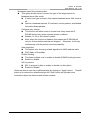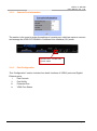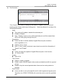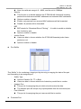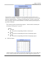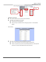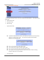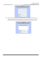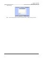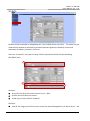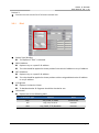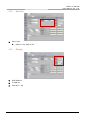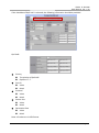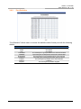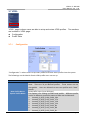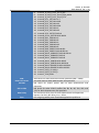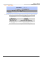
1
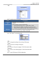
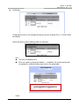
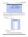
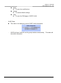
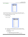
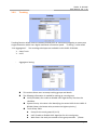
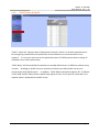
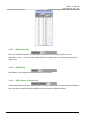
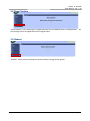
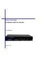
Versa Technology VX-M2024S VDSL2 IP DSLAM User Manual Version 1.00 VDSL2 IP DSLAM User Manual, Ver. 1.00 Page: 1 VDSL2 IP DSLAM User Manual, Ver. 1.00 Copyright by Versa Technology Inc., all right reserved The information in this document has been checked carefully and is believed to be correct as of the date of publication. Versa Technology Inc. reserves the right to make changes in the product of specification, or both, presented in this publication at any time without notice. Versa Technology Inc. assumes no responsibility or liability arising from the specification listed herein. Versa Technology Inc. makes no representations that the use of its products in the manner described in this publication will not infringe on existing or future patents, trademark, copyright, or rights of third parties. Implication or other under any patent or patent rights of Versa Technology Inc. grants no license. All other trademarks and registered trademarks are the property of their respective holders. Page:2 VDSL2 IP DSLAM User Manual, Ver. 1.00 Tables of Contents COPYRIGHT BY VERSATEK TECHNOLOGY INC., ALL RIGHT RESERVED .................................................................... 2 TABLES OF CONTENTS ......................................................................................................................................... 3 CHAPTER 1 INTRODUCTION ............................................................................................................................ 5 1.1 FEATURES ...................................................................................................................................................... 6 1.2 SPECIFICATION ............................................................................................................................................... 8 CHAPTER 2 2.1 HARDWARE INSTALLATION ........................................................................................................... 1 FRONT PANEL................................................................................................................................................. 1 2.1.1 Connectors ............................................................................................................................................ 1 2.1.2 LED Indicators ....................................................................................................................................... 2 2.1.3 Reset Button .......................................................................................................................................... 2 2.2 PIN ASSIGNMENT OF RJ21 CABLE ...................................................................................................................... 2 CHAPTER 3 3.1 WEB CONFIGURATION .................................................................................................................. 4 ADMINISTRATION............................................................................................................................................ 8 3.1.1 IP Address.............................................................................................................................................. 9 3.1.2 Switch Setting...................................................................................................................................... 10 3.1.3 Console Port Information .................................................................................................................... 13 3.1.4 Port Configuration............................................................................................................................... 13 3.1.5 SNMP Configuration ........................................................................................................................... 17 3.1.6 Syslog Setting ...................................................................................................................................... 23 3.1.7 Alarm Configuration ........................................................................................................................... 23 3.1.8 Temperatures & Fan Status ................................................................................................................. 24 3.1.9 Firmware Update ................................................................................................................................ 24 3.1.10 Configuration Backup ..................................................................................................................... 25 3.1.11 SNTP Setting ................................................................................................................................... 26 3.2 L2 FEATURES ............................................................................................................................................... 27 3.2.1 VLAN Configuration ............................................................................................................................ 27 3.2.1.1 Static VLAN ..................................................................................................................................................... 28 3.2.1.2 GVRP VLAN ..................................................................................................................................................... 32 3.2.1.3 QinQ VLAN ..................................................................................................................................................... 34 3.2.2 Trunking .............................................................................................................................................. 36 3.2.3 Forwarding & Filtering ........................................................................................................................ 38 3.2.4 IGMP Snooping ................................................................................................................................... 41 3.2.5 Spanning Tree ..................................................................................................................................... 42 Page: 3 VDSL2 IP DSLAM User Manual, Ver. 1.00 3.2.5.1 System Configuration ......................................................................................................................................43 3.2.5.2 PerPort Configuration .....................................................................................................................................44 3.2.5.3 Instance ...........................................................................................................................................................44 3.2.5.4 Interface ..........................................................................................................................................................45 3.2.6 DHCP Relay & Opt.82 .......................................................................................................................... 46 3.2.6.1 DHCP Option 82 ..............................................................................................................................................47 3.2.6.2 DHCP Relay ......................................................................................................................................................47 3.2.6.3 DHCP Option 82 Router Port ...........................................................................................................................47 3.2.6.4 DHCP Opt. 82 Port Table .................................................................................................................................48 3.3 ACL ........................................................................................................................................................... 49 3.3.1 IPv4 ...................................................................................................................................................... 50 3.3.2 Non-IPv4 .............................................................................................................................................. 51 3.3.3 Binding ................................................................................................................................................ 51 3.4 SECURITY ..................................................................................................................................................... 53 3.4.1 Security Manager ................................................................................................................................ 53 3.4.2 MAC Limit ............................................................................................................................................ 54 3.4.3 802.1x Configuration ........................................................................................................................... 55 3.5 QOS ........................................................................................................................................................... 58 3.5.1 QoS Configuration ............................................................................................................................... 58 3.5.2 ToS/DSCP ............................................................................................................................................. 60 3.6 MONITORING ............................................................................................................................................... 61 3.6.1 Port Status ........................................................................................................................................... 61 3.6.2 Port Statistics ....................................................................................................................................... 62 3.7 VDSL ......................................................................................................................................................... 63 3.7.1 Configuration ...................................................................................................................................... 63 3.7.2 Profile Table ......................................................................................................................................... 65 3.8 RESET SYSTEM .............................................................................................................................................. 66 3.9 REBOOT ...................................................................................................................................................... 66 CHAPTER 4 CONFIGURATION VIA CONSOLE .................................................................................................. 67 APPENDIX ........................................................................................................................................................ 68 Page:4 VDSL2 IP DSLAM User Manual, Ver. 1.00 Chapter 1 Introduction The Versa Technology VX-M2024S VDSL2 IP DSLAM presents the ideal and efficient solution for Telecom, ISP (Internet Service Provider), or SI (System Integration) with 24-port VDSL2 and 2-port gigabit Ethernet combo interfaces (TP and SFP) in the 1.5U height design. The VX-M2024S VDSL2 IP DSLAM offers the benefits of high speed connectivity with an efficient management system, robust layer 2 features with advanced security system, and reliable hardware design with monitoring system. Package Contents: VX-M2024S VDSL2 IP DSLAM Power Cord 19” Rack Mount Brackets and Screws x1 x1 x1 Page: 5 VDSL2 IP DSLAM User Manual, Ver. 1.00 1.1 Features 24 10/100BaseX Ethernet ports and 2 10/100/1000BaseX Ethernet ports Ethernet switch controller Supports SMII or SS-SMII for 10/100BaseX ports Supports GMII/MII/TBI for 10/100/1000BaseX ports All packet buffer and control data memory embedded Flow control support: 802.3x pause frame used for full-duplex ports Collision-based back-pressure for half-duplex ports, carrier-based back-pressure not supported Half- and full-duplex operations: Full-duplex operation supported on 10/100/1000 Mbps ports Half-duplex operation supported on 10/100 Mbps ports only Supports 802.1D bridge self-learning, storing up to 8K+ 256 unicast or multicast addresses Supports automatic age-out period between 1 to 1,000,000 seconds Broadcast storm filtering based on ingress port bandwidth HOL blocking prevention Deadlock relief Auto-polling via MDC/MDIO management interface for auto-configuration of speed, duplex mode, and flow control capability of all Ethernet ports 9K+ jumbo packets supported on per port and per VLAN basis Supports layer 2 source filtering Supports 802.1D Spanning Tree Algorithm and Protocol, and 802.1w Rapid Reconfiguration Flexible per-port VLAN classification option supports port-based VLAN domain and 802.1Q VLAN domain simultaneously Supports Independent VLAN Learning (IVL) and Shared VLAN Learning (SVL) Supports 802.1X Port-based Network Access Control Supports 802.3ad Aggregation of Multiple Link Segments Statistical load-balancing algorithm may be configured to be function of source and destination MAC addresses, ingress port ID, source and destination IP addresses, and TCP/UDP source and destination ports Supports BPDU, LACP, EAPOL suppression based on per port configuration Supports 64 VLAN-dependent Spanning Trees Supports IP multicast and snooping of IGMP and IP multicast routing protocol PDU Including IGMP, CBT, OSPF, and PIM v2 IP multicast packets may be forwarded within single VLAN or across multiple VLANs Cross-VLAN mode allows each egress port to have its own tag rule and VID for IP multicast packets Port mirroring Supports 802.1p Traffic Priority ToS-to-802.1p priority mapping is enabled on per-VLAN basis Flexible per-port prioritization option: The prioritization result can be made available to other switches in the network by replacing priority field in VLAN tag Four priority egress queues per port Page:6 VDSL2 IP DSLAM User Manual, Ver. 1.00 Scheduling algorithms: strict priority or weighted round robin Four RMON groups (1,2,3,9) Supports MIB of RFC1213, 1573, 1757, 1643, 2233 Programmable LED output provides: Serial LED output provides basic status of all Ethernet ports, or Port 24/25 link status and broadcast storm indicator MAC address table synchronization assistance Asymmetric VLAN membership for better network security: Distinguish ingress VLAN member and egress VLAN member Prevents a station to sneak in VLANs set up for common servers Improved VLAN ingress rules may specify: Filtering untagged packets or VLAN tagged packets Filtering packets received on non-ingress VLAN member ports Supports insertion of 2nd tag with different TPID to VLAN-tagged packets Port-based ingress rate policing and egress rate pacing Supports Layer 2/3/4 (Layer 2+) classification: Standard-length IPv4 packets can use layer 2 VLAN-tag ID, IP protocol, Source IP, Destination IP, TCP/UDP Destination Port and Source Port, and TCP SYN field for classification Non-standard or non-IPv4 packets use part of layer 2/3 header for classification Up to 256 different classification rules supported Each classification rule is associated with an action code Packet and byte counters for all classification rules to record match statistics Supports Layer 2+ based VLAN classification scheme: IP subnet based and Protocol-based VLAN achievable by means of layer 2+ classification May override VID in VLAN-tag Supports filtering, redirecting, and/or mirroring of packets based on Layer 2+ classification result Redirects IPv6 packets to IPv6-capable network devices SMAC/SIP bindings for IPv4 packets can be implemented Layer 2+ packet classification result may be used to define packet priority Priority adjustment based on per port profile and per VLAN property Priority of a packet can be upgraded or downgraded based on setting of the ingress port and VLAN Supports protected port, protected port group, and unprotected port group VID in transmitted packets can be replaced by a fixed VID associated with the egress port The VID to be swapped in by egress port can be different than the default VID for untagged ingress packets CPU interface: alternatively 32-bit 33 MHz PCI interface 16-bit PIO interface with three DMA controllers Programmable byte-swap capability for MIB counter memory access Programmable event triggered interrupts allowing software to respond to or ignore an array of exceptions 332-ball PBGA package 1.8V core and SRAM voltage, and 3.3V pad voltage Page: 7 VDSL2 IP DSLAM User Manual, Ver. 1.00 1.2 Specification Hardware Case: 1.5U High Pizza-Box Type Protocol Support: IGMP Snooping/Proxy v1, v2 and v3 Multicast Forwarding with IGMP Snooping v1 Interfaces: and v2 (RFC 1112 and RFC 2236) 24 VDSL2 Ports Multicast MAC address mapping Two RJ-45 100/1000Mbps Ethernet Combo Up to 512 Multicast Channels Ports Profile-based Multicast Access Control (up to Management Ethernet 1 x RS-232 Serial Console POTS Splitter LED Indicators: SYS, ALM, LINK, ACT 24 x VDSL LEDs Standards Support: VDSL2 ITU-T G.993.2 VDSL2 Profiles: 8a, 8b, 8c, 8d, 12a, 12b, 17a and 24 profiles) Fast and Normal Leave Modes Security: L2 Frame Filtering by MAC Addresses L3 Frame Filtering by IP Addresses, protocol ID, and TCP/UDP DHCP and ARP Broadcasting Frames Filtering Support Secured Forwarding Management: 30a Support OAM&P Functions 802.1d L2 Bridging Support VLAN Priority Queue (IEEE 802.1p) DHCP Server/Client/Relay Support CoS, ToS, DSCP, etc. IEEE 802.1q VLAN (Port-based VLAN and Support SNMP v1/v2/v3 and MIB I/II Protocol-Based VLAN) Web-based Graphical User Interface, Telnet, CLI VLAN Stacking (Q-in-Q) IEEE 802.1p Spanning Tree Protocol (STP) IEEE 802.3ad Link Aggregation and SSH Operating Requirements: Operating Temperature: -10°C to 50°C Storage Temperature: -40°C to 70°C Relative Humidity: Up to 95% (non-condensing) * Versatek reserves the right to change specifications without prior notice. All brand names and trademarks are property of their respective owners. All rights reserved. Page:8 VDSL2 IP DSLAM User Manual, Ver. 1.00 Chapter 2 Hardware Installation This chapter shows the front panel and how to install the hardware. 2.1 Front Panel VX-M2024S includes all connectors and LED indicators on its front panel so only a few installations are required in order to build the network solution. 2.1.1 Connectors POTS VX-M2024S includes 24 build-in splitters, POTS, with a Telco-50/ RJ-21 cable for telephone services. LINE LINE is for connecting 24 VDSL2 ports with a Telco-50/ RJ-21 cable. ALARM For alarm inputs and outputs. CONSOLE Users are able to access VX-M2024S locally with CONSOLE port. Via CONSOLE, users are able to configure VX-M2024S with menu-driven interface with any terinal emulation program, such as, Hyperterminal and Teraterm. (115200, 8, None, 1, None) GE1 & GE2 For connecting Gigabit Ethernet, VX-M2024S provides Gigabit Ethernet combo interfaces, TP and SPF. TP: 10/100/1000 BaseT copper (RJ-45 connector). SFP: 1000 Base-SX/LX mini-GBIC slot. POWER The connector is for 100V ~ 240V AC power inputs (50Hz~60Hz, 1.5A). Page: 1 VDSL2 IP DSLAM User Manual, Ver. 1.00 2.1.2 LED Indicators VDSL LINK (1 ~ 24) Blinking On Off VDSL2 link is active VDSL2 link is ready VDSL2 link is down Alarm is detected No alarm Power On Power Off (transmitting data or training) System up RUN/ALARM PWR GE1/GE2 LINK/ACT SPEED 2.1.3 Reset Button The reset buttons allows users to reboot the VDSL2 IP DSLAM or load the default settings. Press the reset button for Action 1 ~ 5 seconds Reboot the IP DSLAM Load the default settings 2.2 Pin Assignment of RJ21 Cable Page:2 VDSL2 IP DSLAM User Manual, Ver. 1.00 PIN COLOR PORT PIN COLOR PORT PIN COLOR PORT 1 26 2 27 3 28 4 29 5 30 6 31 Black Orange Black Blue Red Gray Red Brown Red Green Red Orange P24 7 62 8 33 Red Blue White Gray P18 P23 P22 P21 P20 P19 P17 9 34 10 35 11 36 12 37 13 38 14 39 White Brown White Green White Orange White Blue White Blue White Orange P16 15 40 16 41 White Green White Brown P10 P15 P14 P13 P12 P11 P9 17 42 18 43 19 44 20 45 21 46 22 47 White Gray Red Blue Red Orange Red Green Red Brown Red Gray P8 23 48 24 49 Black Blue Black Orange P2 P7 P6 P5 P4 P3 P1 Page: 3 VDSL2 IP DSLAM User Manual, Ver. 1.00 Chapter 3 Web Configuration The VDSL2 IP DSLAM allows users to manage and change its configurations with web browsers. Users are able to login the web management system with any standard web browser, such as, Internet Explorer, Firefox, etc. Default IP Address 192.168.0.100 Default User Name admin Default Password admin TABLE 1 DEFAULT LOGIN INFORMATION Note: Please make sure the IP address is correct once the IP of the management web site is changed. Once users are able to login the web management page successfully, the login message box will pop up as the following image. Page:4 VDSL2 IP DSLAM User Manual, Ver. 1.00 Please key in the correct login information and the main page of the management will be showed as the following image. HOME page of the management system includes three major sections. 1. Title section Page: 5 VDSL2 IP DSLAM User Manual, Ver. 1.00 2. Menu section “Menu” section is located on the left hand side of the page and users are allowed to change the configuration and review the status of the device by interacting this section. 3. Information section “Information” section presents the real-time LED status and the current status of the IP DSLAM. Note: users are able to go back HOME page anytime by clicking on “Home” on the menu section. The following sections will introduce users the features of the VDSL2 IP DSLAM. Administration (3.1) L2 Features (3.2) Page:6 VDSL2 IP DSLAM User Manual, Ver. 1.00 ACL (3.3) Security (3.4) QoS (3.5) Monitoring (3.6) VDSL (3.7) Reset System 3.8) Reboot (3.9) Page: 7 VDSL2 IP DSLAM User Manual, Ver. 1.00 3.1 Administration “Administration” section is for users to manage the VDSL2 IP DSLAM, including the IP address, switch settings, etc. It includes the following detail functions. IP Address Switch Setting Console Port Info Port Configuration SNMP Configuration Syslog Setting Alarm Configuration Temperatures & Fan Status Firmware Update Configuration Backup SNTP Setting Page:8 VDSL2 IP DSLAM User Manual, Ver. 1.00 3.1.1 IP Address “IP Address” function includes four information and users are allowed to change these information: DHCP mode - Disable or enable DHCP mode The value of this mode will decide whether the IP address is a static IP address or a dynamic IP address. IP address Subnet mask Default gateway - Page: 9 VDSL2 IP DSLAM User Manual, Ver. 1.00 3.1.2 Switch Setting “Switch Setting” presents information of the switch in the following sub-functions. only “Misc Config” section allows users to change the settings of the switch. Note: Basic In “Basic” tab, the basic information of the VDSL2 IP DSLAM is presented. - Model name Description MAC address Firmware version Board type - Hardware version Page:10 VDSL2 IP DSLAM User Manual, Ver. 1.00 Module Info This section shows the information of uplinks, Gigabit Ethernet 1 and Gigabit Ethernet 2. Note: in the following contents, these two uplinks will be called Mod1 and Mod2. Misc Config Users are allowed to modify the following details of the switch. - MAC address age-out time This value is for setting up how many seconds that an inactive MAC address remains. - Turn on port interval This value for setting up the time interval that the CPU port should be enabled after flooding attacks. Note: 0 means never enable the CPU port. - Broadcast storm filter mode This feature is to set up the threshold value of broadcast traffic for ports. Options: off, 1/2, 1/4, 1/8 or 1/16 (Note: the value is the percentage of the port’s ingress bandwidth used by broadcast traffic. Page: 11 VDSL2 IP DSLAM User Manual, Ver. 1.00 - Broadcast storm filter packets select This option allows users to choose the type of the target packet for broadcast storm filter mode. If there is no type is chosen, this means broadcast storm filter mode is off. Options: broadcast packets, IP multicast, control packets, and flooded unicast/multicast packets. - Collisions retry forever This function will allow users to choose how many times the IP DSLAM should retry when a packet meets a collision. Disable, 16, 32 or 48 collision number Note: when the function is disabled, this means the IP DSLAM will retry for 6 times before packets are dropped. Otherwise, it will retry continuously until the packet is sent successfully. - Hash algorithm This option is for choosing a hash algorithm for MAC address table. CRC-Hash or DirectMap. - IP/MAC binding This feature allows user to enable or disable IP/MAC binding function. Enable or disable. 802.1x protocol 802.1x protocol is able to enable or disable via this option. Enable or Disable. Users are able to save the modified settings by clicking on “Apply” button. “Default” button is for restore the default settings; and “Help” button will provide some information about the features with another window. - Page:12 VDSL2 IP DSLAM User Manual, Ver. 1.00 3.1.3 Console Port Information The section is for users to review the settings of console port, which lets users to connect and manage the VDSL2 IP DSLAM in Command Line Interface (CLI) mode. Connect to PC via DB9-RJ45 console cable. 3.1.4 Port Configuration “Port Configuration” section includes four detail functions of VDSL2 ports and Gigabit Ethernet ports: i. Port Controls ii. Port Sniffer iii. Protected Port iv. VDSL Port Status Page: 13 VDSL2 IP DSLAM User Manual, Ver. 1.00 Port Controls “Port Control” is for users to setting up the details of Gigabit Ethernet ports and trunking ports if there exists any trunking ports. Users are allowed to configure the following parameters. - State This option will enable or disable the selected port. Enable or Disable Note: “Disable” means to turn off the selected port; and this means there will be no traffic going through this port. - Negotiation Users are able to decide whether Gigabit Ethernet ports should be auto-negotiable or not. Options: auto or force Note: If “force” mode is selected, users have to provide the information of “Speed” and “Duplex”. - Speed Users can setup the speed of Gigabit Ethernet ports in this function. 10, 100 or 1000 - Duplex Half or Full - Flow Control Options: enable or disable Enable: send a PAUSE signal to the sender and halts the traffic for a period of time. Disable: drop the exceed packets when there are too much packets to process. - Rate Control Users are able to set up the specific rate for both ingress and egress ports. Therefore, the VDSL2 IP DSLAM will control the rate to meet the specified rate. Page:14 VDSL2 IP DSLAM User Manual, Ver. 1.00 - Security This function is to decide whether the IP DSLAM will forward all incoming packets from both secured MAC addresses and unknown MAC addresses. Options: enable or disable Enable: only packets from secured MAC addresses will be forwarded. Disable: all packets will be forwarded. - BSF BSF stands for “Broadcast Storm Filtering”. this function by port. Options: enable or disable - Note: the valid rate range is 0 ~ 8000; and the unit is 128Kbps. It is able to enable or disable Jumbo Frame Users are able to choose whether the IP DSLAM forwards jumbo frame packets or not. Options: enable or disable Port Sniffer “Port Sniffer” is for monitoring a target port by mirroring or copying the data of the port and forwarding to an assigned port. - Sniffer Type Options: Disable, Rx, TT, or Both. Users are able to choose what kind of data they would like to monitor. - Analysis Port This port is for assigning the port which should receive the data. The analysis port will accept only copied packets from the monitored port. - Port & Monitor This port is for assigning the port users would like to monitor. Protected Port Page: 15 VDSL2 IP DSLAM User Manual, Ver. 1.00 “Protected Port” isolates a protected port from its neighbor ports and other ports in different protected groups. However, it is allowed for a protected port to communicate with other unprotected ports. By setting up protected ports, it is able to ensure that there is no traffic, such as unicast, broadcast, or multicast, between protected ports on the VDSL2 IP DSLAM. This function provides two protected port groups. Users are able to choose ports and assign to either group 1 or group 2. - Options: Protected Click on the corresponding checkbox to select a port. Group1 Click on the corresponding radio button for assigning a group. Group2 Click on the corresponding radio button for assigning a group. VDSL Port Status “VDSL Port Status” allows users to monitor the current information of each VDSL port, such as, status, upstream rate, downstream rate, SNR margins for upstream and Page:16 VDSL2 IP DSLAM User Manual, Ver. 1.00 downstream, and firmware version. In addition, it includes “Advance” button for checking the details of the selected port in another window, as the following. 3.1.5 SNMP Configuration “SNMP” stands for “Simple Network Management Protocol”, which is a standard protocol for managing network devices. SNMP is used commonly in Network Management Systems (as known as, NMS) to monitor network devices. In addition, MIBs (Management Information Bases) is a kind of file which is used to store all the data of managed network devices in NMS according to SNMP standard protocols. VDSL2 IP DSLAM supports three versions of SNMP: SNMPv1, SNMPv2c and SNMPv3. In SNMP Configuration page, it includes the followings sections. System Options - Name Page: 17 VDSL2 IP DSLAM User Manual, Ver. 1.00 The name of the VDSL2 IP DSLAM - Location The location of the switch - Contact The contact information (the name of a person or organization) - SNMP Status Options: Enable or Disable This option is for enabling or disabling SNMP function. Community Strings This section is for setting up the password for accessing SNMP system. - Current Strings The list of existing password strings - New Community String For the information of a new password String: password Options: RO (read only) or RW (read and write) - Add Add button: for adding new information on the right hand side of the table to the community list. - Remove Remove button: for removing a password from the left hand side of the table. Trap Manager - Current Managers The list of existing SNMP servers. - New Manager The information of new trap manager. Page:18 VDSL2 IP DSLAM User Manual, Ver. 1.00 IP Address: the IP address of the trap manager. Community: the password for accessing the trap manager. - Add For adding new manager. - Remove For removing the information of existing manager. SNMPv3 Group - Current Strings The list of current SNMPv3 groups. - SNMP Group Group Name: the name of the SNMPv3 group. V1/V2c/USM: the security model of this group. Security Name: the security name string of this group. - Add For adding new SNMPv3 group. Remove For removing an existing SNMPv3 group. SNMPv3 View - “SNMPv3 view” is to offer or deny access to the complete features or parts of features of the VDSL2 IP DSLAM. - Current Strings Page: 19 VDSL2 IP DSLAM User Manual, Ver. 1.00 The name of current SNMPv3 views. - SNMP View View Name: the name of the new SNMPv3 view. Included/Excluded: the OID should be included or excluded from the SNMP view. View Subtree: the feature OID of this view. View Mask: the subnet mask of this view. - Add For adding the new SNMPv3 view. - Remove For removing a selected SNMPv3 view from the current strings table. SNMPv3 Access “SNMPv3 Access” section is for managing SNMPv3 access control, which is different from the access control defined by SNMPv1 and SNMPv2. SNMPv3 access sets up SNMP access levels based on contexts, groups and users, rather than on IP addresses and community strings. - Current Strings The list of current SNMPv3 access list - SNMP Access Group Name: the group name of the new SNMPv3 access V1/V2c/USM: the security model V1: Reserved for SNMPv1 V2c: Reserved for SNMPv2c USM: User-based Security Model SNMP Access: the security model Options: NoAuth/ Auth/ Authpriv NoAuth: None authentication and none privacy Auth: Authentication and none privacy Authpriv: Authentication and privacy Read View: the view name for each group that defines the list of OIDs that Page:20 VDSL2 IP DSLAM User Manual, Ver. 1.00 are accessible for reading by users belonging to the group. Write View: the view name for each group that defines the list of OIDs that are able to be created or modified by users of the group. Notify View: the view name for each group that defines the list of notifications that can be sent to each user in the group. - Add For adding the new SNMPv3 access - Remove For removing an access from Current Strings list SNMPv3 USM-User “SNMPv3 USM-User” section is for setting up the details of USM (User-based Security Model) security model. USM provides different types of security levels using various authentication and privacy protocols. - Current Strings The list of current SNMPv3 USM-user. - SNMP usm-user SNMP User Name the name of new USM user Auth Type The authentication type Options: none or md5 Auth Key The authentication password of the USM user Private Key The password for the privacy protocol type - Add For adding the new SNMPv3 USM-user - Remove For removing a SNMPv3 USM-user from the current list Page: 21 VDSL2 IP DSLAM User Manual, Ver. 1.00 Page:22 VDSL2 IP DSLAM User Manual, Ver. 1.00 3.1.6 Syslog Setting “Syslog” function is supported in this VDSL2 IP DSLAM system. The system will send logs to a remote log system. In this system, three events will be reported to the remote log system: cold start, warm start and link change. The followings are necessary for connecting the remote syslog server. Syslog server IP: the IP address of the remote syslog server IP. Log level: Options: None, Major, or All 3.1.7 Alarm Configuration “Alarm Configuration” is distinguished into two tables: Configure Alarm Information and Alarm Information. Users are able to setup alarms and monitor alarm status. Configure Alarm Information (configuration section) - Alarm Item Total of four alarms can be set in the VDSL2 IP DSLAM - Admin Options: Disable or Enable - Security The level of the alarm Title The name of the alarm Alarm Information (monitor section) - Page: 23 VDSL2 IP DSLAM User Manual, Ver. 1.00 - Alarm Item Admin - Security Title 3.1.8 Temperatures & Fan Status “Temperatures & Fan Status” allows users to monitor the real-time information of the VDSL2 IP DSLAM’s temperatures and FANs. 3.1.9 Firmware Update “Firmware Update” allows users to upgrade firmware by themselves. choose upgrading firmware through TFTP or HTTP. Users are able to Page:24 VDSL2 IP DSLAM User Manual, Ver. 1.00 3.1.10 Configuration Backup Users are able to load or backup configurations via “Configuration Restore” function. This function includes two tabs: “TFTP Restore Configuration” and “TFTP Backup Configuration”. TFTP Restore Configuration This section is for load the settings from a configuration file. Users are able to upload the settings by TFTP or HTTP. TFTP Backup Configuration This area allows users to download the current configuration through TFTP or HTTP. Page: 25 VDSL2 IP DSLAM User Manual, Ver. 1.00 3.1.11 SNTP Setting SNTP stands for “Simple Network Time Protocol”. SNTP is a simpler version of “Network Time Protocol” (NTP), which is a system for synchronizing the clocks of network computer systems. By enabling SNTP function, users are able to configure this switch to send time synchronization requests to the assigned servers with servers’ IP addresses. - SNTP To enable or disable SNTP feature. Options: Enable or Disable. - SNTP server IP The IP address of the assigned SNTP server. - UTC Type To decide the time zone. Options: After-UTC: UTC+hh (hh: hours) For example, Taipei (UTC+08), choose “After-UTC”. Before-UTC: UTC-hh (hh: hours) For example, San Francisco (UTC-08), choose “Before-UTC”. - Time Range This field is for setting up the hour data in “UTC-hh/UTC+hh”. For example, UTC-08, then, choose “Before-UTC” in UTC type and fill in “8” in Time Range. - Time This section is for displaying the current time once the switch is connected to the assigned NTP server. Page:26 VDSL2 IP DSLAM User Manual, Ver. 1.00 3.2 L2 Features VDSL2 VX-M2024S IP DSLAM offers a flexible L2 features, as the following functions: VLAN Configuration Trunking Forwarding & Filtering IGMP Snooping Spanning Tree DHCP Relay & Opt.82 3.2.1 VLAN Configuration “VLAN” stands for “Virtual Local Area Network” or “virtual LAN”. It is a concept of separating and grouping LAN segments by a common set of requirements. VLAN presents couple benefits, such as, simplifying network design, enhancing bandwidth performance and improving, etc. The VDSL2 IP DSLAM supports three kinds of VLAN algorithms: Static VLAN GVRP VLAN QinQ VLAN Page: 27 VDSL2 IP DSLAM User Manual, Ver. 1.00 3.2.1.1 Static VLAN Static VLAN function allows users to setup and manage VLAN groups manually. VLAN Operation Mode - No VLAN To disable VLAN mode. - Port-Based VLAN To setup VLAN groups by ports. 802.1Q VLAN To setup VLAN groups by 802.1Q VLAN tags. Basic - “VLAN Information” displays all VLAN groups stored already. allow users to manage VLAN groups. The following buttons Note: The VLAN mode of VLAN operation mode is the global setting of “Basic” and “VLAN Filter”. Page:28 VDSL2 IP DSLAM User Manual, Ver. 1.00 - Add To create a new VLAN group. Name Description VLAN Name VID VLAN Members CPU Port The name of this VLAN group VLAN ID There are three columns in this section. Ports (left-hand side): Port1 ~ Port24, Mod1, Mod2 Add or Remove (middle): for adding or removing a port Selected Ports (right-hand side): the VLAN group members Click on this checkbox to choose this VLAN group as the management group of this VDSL2 IP DSLAM. Click “Apply” to set up tag mode. - Edit To change the settings of an existing VLAN group. - Delete To remove an existing VLAN group. - PrePage To move to the previous page of VLAN information table. - NextPage To move to the following page of VLAN information table. - Help To open FAQ page of VLAN configuration. Page: 29 VDSL2 IP DSLAM User Manual, Ver. 1.00 VLAN filter VLAN filter function is for setting the filtering rules for all ports (Port1 ~ Port24, Mod1 and Mod2). Users are able to define filtering rules for each port. - NO The list of available ports. Click on a port to change the details. In addition, the current setups will be showed in a different table right next to the setup table. - PVID Page:30 VDSL2 IP DSLAM User Manual, Ver. 1.00 The VLAN ID of ingress packets. Two filtering rules are available in VLAN Filtering function of this VDSL2 IP DSLAM. - Ingress Filtering 1 Only these ingress packets with the assigned VLAN ID are able to pass through this port. Options: Enable or Disable (disable filtering function) - Ingress Filtering 2 Enabling this rule will drop all untagged packets. Options: Enable (only packets with the assigned VLAN ID can pass through this port) or Disable (accept all packets) Page: 31 VDSL2 IP DSLAM User Manual, Ver. 1.00 3.2.1.2 GVRP VLAN GVRP stands for “GARP (Generic Attribute Registration Protocol) VLAN Registration Protocol” or “Generic VLAN Registration Protocol”. GVRP VLAN method follows IEEE 802.1Q specification and defines tagging frames with VLAN configuration data. This meaning allows VDSL2 IP DSLAM to exchange VLAN configuration information with other network devices dynamically. - GVRP Setting For setting up GVRP configurations GVRP Options: Enable or Disable Port & GVRP Port1 ~ Port24, Mod1, Mod2 & corresponding checkbox. Click on the checkboxes to choose GVRP group members. Page:32 VDSL2 IP DSLAM User Manual, Ver. 1.00 Apply To save the modifications. Default To restore default settings. Help To open the FAQ page of GVRP VLAN. - GVRP Table This table is for displaying current GVRP VLAN information. - GVRP will learn VLAN ID and its group member automatically. show this information. This table will Page: 33 VDSL2 IP DSLAM User Manual, Ver. 1.00 3.2.1.3 QinQ VLAN QinQ VLAN function allows users or service providers to separate traffic service for different customers by adding service provide VLAN tags and customer VLAN IDs. In this function, settings are divided into two parts: QinQ Port Setting QinQ Tunnel Setting - QinQ Port Setting This section is for setting up QinQ mode, TPID, and group members. The followings are the details that are required to be filled in for setting QinQ function. QinQ: Disable or Enable QinQ TPID: TPID stands for “Tag Protocol Identifier”. TPID is the Ethertype value for 802.1Q encapsulation. Page:34 VDSL2 IP DSLAM User Manual, Ver. 1.00 Standard Ethertype value: 0x8100 (Default value) Range: 0x0800 ~ 0xFFFF (hexadecimal value). Port Table: QinQ: for choosing which port should be enabled with QinQ mode. QinQ Uplink: for setting up an uplink port of this QinQ group. QinQ Port - QinQ Uplink QinQ Tunnel Setting Tunnel ID Tunnel VID Page: 35 VDSL2 IP DSLAM User Manual, Ver. 1.00 3.2.2 Trunking Trunking function allows users to combine several ports or connections together to create one single connection which has a higher and faster connection speed. “Trunking” is also called “Link Aggregation”. Two trunking techniques are available in this VDSL2 IP DSLAM: Static Trunk LACP - Aggregator Setting This section allows users to setup trunking groups and details. The following information is needed for setting up a trunk group. LACP (checkbox): for enable or disable LACP algorithm by check on the checkbox. System Priority: this value is for identifying the active LACP of this VDSL2 IP DSLAM. (Note: the lowest value presents the highest priority.) Trunk Group Table Group ID: the trunk group ID (1~13) LACP: Enable or Disable LACP algorithm for this trunk group. Work Ports: the total port number of the group member. (Please Page:36 VDSL2 IP DSLAM User Manual, Ver. 1.00 select the group number in the following port list.) Port List The selected port list. The number should be matched to the value of “Work Ports”. - Aggregator information This section allows users to review trunk information. Two data are reviewed in this section: Group Key: the trunk group ID. Port No: the port member of this trunk group. (Port1 ~ Port24, Mod1, Mod2) - Static Activity This area is for setting up LACP mode (active or passive) Active: the active port will send LACP packets automatically. Passive: the passive port will not send LACP packets but it will respond if and only if it receives LACP packets from the other end. Page: 37 VDSL2 IP DSLAM User Manual, Ver. 1.00 3.2.3 Forwarding & Filtering “Forwarding & Filtering” function is for users to setup rules about packets. Four ways to setup these rules: Dynamic MAC Table Static MAC Table MAC Filtering - - Dynamic MAC Table The VDSL2 IP DSLAM will learn devices’ MAC addresses dynamically and record these addresses into MAC address table. This section will show all the found MAC addresses as the following table. Clear: to clear the dynamic MAC address table. Top: to show the first page of the MAC address table. Prev: to go to the previous page of the MAC address table. Next: to go to the next page of the MAC address table. (Note: if there is nothing showed, it means this is the end page.) Static MAC Table Page:38 VDSL2 IP DSLAM User Manual, Ver. 1.00 Users are able to fill up the MAC addresses of devices connected to the switch. By adding a static MAC address, the switch will save the information permanently and will not attend to learn the MAC address of this device when the device is online. Page: 39 VDSL2 IP DSLAM User Manual, Ver. 1.00 - MAC Filtering Users are able to define and drop unwanted traffic in “MAC Filtering” function. Page:40 VDSL2 IP DSLAM User Manual, Ver. 1.00 3.2.4 IGMP Snooping “IGMP” stands for “Internet Group Management Protocol”. IGMP allows hosts and routers to build multicast group memberships. IGMP snooping presents the process of IGMP network traffic listening. With this feature, VDSL2 IP DSLAM is able to listen to IGMP conversation between hosts and routers. The switch is able to maintain a relation map of links and IP multicast streams. The following settings are needed in order to allow IGMP snooping work properly. IGMP Protocol: to enable or disable IGMP function. IGMP Fastleave: to enable or disable IGMP Fastleave mode. IGMP Querier: to enable or disable IGMP Querier mode. Multicast Group: the multicast group list table. Page: 41 VDSL2 IP DSLAM User Manual, Ver. 1.00 3.2.5 Spanning Tree Spanning Tree (also known as, STP) is a network protocol which is defined by IEEE 802.1 D standards for preventing bridge loops and broadcast radiation. In addition, STP allows redundant links to provide automatic backups. Most commonly known STP algorithms are STP (Spanning Tree Protocol), RSTP (Rapid Spanning Tree Protocol), and MSTP (Multiple Spanning Tree Protocol). This VDSL2 IP DSLAM supports both STP and MSTP. In addition, in this Switch, users are able to set up STP either for the whole system of the Switch or for each individual port. In Spanning Tree function, there are four major setup pages as the following sections. - System Configuration PerPort Configuration Instance Interface Page:42 VDSL2 IP DSLAM User Manual, Ver. 1.00 3.2.5.1 System Configuration “System Configuration” allows users setting up the details of STP function. In addition, the information of the root node of the STP will be displayed in this page. - Configure Spanning Tree Parameters STP State - To enable or disable STP function. Note: to enable STP function, users are required to click on this checkbox and press “Apply” button. Then, after the saving process is completed, users are able to fill up the rest of the information. STP protocol version STP or MSTP Region Name Name of STP tree Revision Level The level of STP tree Max Hops Hop number Priority Maximum Age The waiting time (seconds) before the switch attempts to reconfigure. Hello Time The time (seconds) the switch will send BPDU packets to check STP current status. Forward Delay Root Bridge Information Priority MAC Address Region Name Revision Level Page: 43 VDSL2 IP DSLAM User Manual, Ver. 1.00 Max Hops Root Path Cost Maximum Age Hello Time Forward Delay 3.2.5.2 PerPort Configuration “PerPort Configuration” is for setting up Spanning Tree mode for each individual port. 3.2.5.3 Instance Page:44 VDSL2 IP DSLAM User Manual, Ver. 1.00 3.2.5.4 Interface Page: 45 VDSL2 IP DSLAM User Manual, Ver. 1.00 3.2.6 DHCP Relay & Opt.82 “DHCP” stands for “Dynamic Host Configuration Protocol”, which is a network protocol that is for configuring network devices dynamically so these devices can communicate on an IP network. It is a service that runs at the application layer of TCP/IP protocol stack to assign IP addresses to its clients dynamically. “DHCP Relay” will forward DHCP broadcasts to multiple DHCP servers in different subnets using unicasts. By doing so, DHCP clients on subnets not directly served by DHCP servers can communicate with DHCP servers. In addition, “DHCP Relay Information Options 82”, is defined in RFC 3046 and RFC 3993, allows a DHCP Relay agent to insert circuit specific information to a request which is forwarded to a DHCP server. Page:46 VDSL2 IP DSLAM User Manual, Ver. 1.00 3.2.6.1 DHCP Option 82 Users are allowed to enable or disable DHCP Option 82 by choosing the options in the drop-down menu. To setup DHCP Option 82 for this switch, users are required to enable this option first. 3.2.6.2 DHCP Relay DHCP Relay is for enabling or disabling DHCP Relay function. 3.2.6.3 DHCP Option 82 Router Port “DHCP Option 82 Router Port” allows users to choose the relay port for DHCP Option 82 feature. Users are able to specific one port between Port1 to Port24 or Mod1 to Mod2. Page: 47 VDSL2 IP DSLAM User Manual, Ver. 1.00 3.2.6.4 DHCP Opt. 82 Port Table This section is for defining DHCP Option 82 and port information. - Option: the checkbox for enabling or disabling DHCP Relay Information Option 82 function. Relay IP: for assign the IP address of the port. Page:48 VDSL2 IP DSLAM User Manual, Ver. 1.00 3.3 ACL Packets can be forwarded or dropped by ACL rules include IPv4 or non-IPv4. The switch can be used to block packets by maintaining a table of packet fragments indexed by source and destination IP address, protocol, and so on. There are 2 main ACL rule types to setup: Packet Type (IPv4 and Non-IPv4) and Binding (SIP-SMAC-Port). 1 2 3 Section 1: Group ID: the ID of this Access Control List (1 ~ 200). Action: Permit or Deny the access VLAN: Any or VID (a specific VLAN ID) Section 2: Port ID: the target port of this access control list should be applied to. (0: don’t care/1 ~ 10) Page: 49 VDSL2 IP DSLAM User Manual, Ver. 1.00 Section 3: Current List: the current list of all access control lists. 3.3.1 IPv4 Packet Type/ Binding The option of “IPv4” is selected. SRC IP Address Options: Any or a specific IP address The rule should be applied on these packets from which IP address or any IP address. DST IP Address Options: Any or a specific IP address The rule should be applied on these packets with an assigned destination IP address or any IP address. IP Fragment Options: Uncheck or Check To decide whether IP fragment should be checked or not. L4 Protocol Options are as the following table L4 Protocol Type Options Data Any TCP UDP Any, ICMP, or IGMP Any, FTP, or HTTP Any, DHCP, TFTP, NetBIOS Protocol No. Port No. Port No. Page:50 VDSL2 IP DSLAM User Manual, Ver. 1.00 3.3.2 Non-IPv4 Ether Type Options: Any, ARP, or IPX 3.3.3 Binding MAC Address IP Address Port ID (1 ~ 10) Page: 51 VDSL2 IP DSLAM User Manual, Ver. 1.00 If the checkbox of QoS VoIP is selected, the following information should be provided. QoS VoIP: Priority The priority of QoS VoIP Options: 0 ~ 7 Port ID Value Mask Protocol Value Mask Source Port Value Mask Destination Port Value Mask Note: all values are in HEX format. Page:52 VDSL2 IP DSLAM User Manual, Ver. 1.00 3.4 Security “Security” section allows users to enhance the security level of this VDSL2 IP DSLAM. It includes the following functions: Security Manager MAC Limit 802.1x Configuration 3.4.1 Security Manager “Security Manager” allows users to change the user name and password for login purpose. Only one set of user name and password is stored in the Switch. The followings are the necessary information for this section. User Name Assign/Change Password Reconfirm Password Note: the default user name and password are “admin” and “admin”. Page: 53 VDSL2 IP DSLAM User Manual, Ver. 1.00 3.4.2 MAC Limit MAC limit allows users to set a maximum number of MAC addresses to be stored in the MAC address table. The MAC addresses chosen to be stored in MAC address table is the result of first-come-first-save policy. Once a MAC address is stored in the MAC address table, it stays in until it is aged out. When an “opening” is available, the switch stored the first new MAC address it sees in that opening. All packets from MAC addresses not in the MAC address table should be blocked. Two sections are in MAC Limit page: - Configure MAC Limit Users are able to setup MAC limit rules for each port in this section by providing the information as the followings: MAC Limit: enable or disable MAC limit function. Limit: the maximum number of MAC addresses should be blocked. - MAC Limit Port Status This section allows users to review the status of ports and MAC limits. Page:54 VDSL2 IP DSLAM User Manual, Ver. 1.00 3.4.3 802.1x Configuration 802.1x makes use of the physical access characteristics of IEEE 802 LAN infrastructures in order to provide a means of authenticating and authorizing devices attached to a LAN port that has point-to-point connection characteristics, and of preventing access to that port in cases in which the authentication and authorization process fails. Note: The default 802.1x setup is disabled, hence, users will not be able to see “802.1x Configuration” page as showed above. To enable 802.1x, go to “Administration Switch setting Misc Configs” page to enable the 802.1x protocol field. After enable the function, the 802.1x configuration page will be shown up. Three sections are in 802.1x configuration function: - System Configuration Radius Server IP: the IP address of the authentication server. Server Port: the UDP port number used by the authentication server to authenticate (default: 1812). Accounting Port: the UDP port number used by the authentication server to retrieve accounting information (default: 1813). Shared Key: the password between the switch and the authentication server. NAS, Identifier: the name of this switch. Page: 55 VDSL2 IP DSLAM User Manual, Ver. 1.00 - PerPort Configuration “PerPort Configuration” allows users to setup the authorization mode of 802.1x for each port and review the authorization status of each port. The VDSL2 IP DSLAM allows users to setup four authorization modes: FU: force the specific port to be unauthorized. FA: force the specific port to be authorized. AU: the state of the selected port was determined by the outcome of the authentication. NO: the selected port didn’t support 802.1x function. - Misc Configuration “Misc Configuratioin” page allows users to change miscellaneous setups of 802.1x function. Quiet Period: Used to define periods of time during which it will not attempt to acquire a supplicant (default time: 60 seconds). Tx Period: Used to determine when an EAPOL PDU is to be transmitted (Default value is 30 seconds). Page:56 VDSL2 IP DSLAM User Manual, Ver. 1.00 Supplicant Timeout: Used to determine timeout conditions in the exchanges between the supplicant and authentication server (default value: 30 seconds). Server Timeout: Used to determine timeout conditions in the exchanges between the authenticator and authentication server (default value: 30 seconds). ReAuthMax: Used to determine the number of re-authentication attempts that are permitted before the specific port becomes unauthorized (default value: 2 times). Reauth Period: Used to determine a nonzero number of seconds between periodic re-authentication of the supplications (default value: 3600 seconds). Page: 57 VDSL2 IP DSLAM User Manual, Ver. 1.00 3.5 QoS This switch provides quality of service (QoS) to prioritize the packet forwarding when traffic congestion happens. This switch supports two QoS functions: port-based (4-level output queue) and 802.1p (8-level priority to 4-level queue mapping). In addition, Strict and weight Round Robin (WRR) QoS modes are supported. 3.5.1 QoS Configuration “QoS Configuration” page includes two sections as the followings: - QoS Configuration Three QoS modes are supported in this switch: First Come First Service The sequence of packets sent is depending on arrive orders. This mode can be regarded as QoS is disabled. All High before Low The high priority packets sent before low priority packets. WRR Page:58 VDSL2 IP DSLAM User Manual, Ver. 1.00 Weighted Round Robin. Select the preference given to packets in the switch's high-priority queue. These options represent the number of higher priority packets sent before one lower priority packet is sent. For example, 8 Highest:4 second-high means that the switch sends 8 highest-priority packets before sending 4 second-high priority packets. - 802.1p priority The switch supports 8 802.1p priority queues with 4 priority levels (Highest, Second-High, Second-Low, and Lowest). This section is for setting up the maps of priority queues and priority levels. PerPort Configuration “PerPort Configuration” section allows users to setup the priority level for each port. Users are able to setup QoS algorithm with Port-Based algorithm in this page. Port Priority: Options: Disable, 0 ~ 7. Page: 59 VDSL2 IP DSLAM User Manual, Ver. 1.00 3.5.2 ToS/DSCP “ToS/DSCP” page is where users can set up priority algorithm for each queue and packets. In IPv4 packet header, there is a ToS byte. “ToS” stands for “Type of Service”, and ToS algorithm uses first 3 bits for priority level. algorithm, it will take first 6 bits for priority level. However, for DSCP IPv4 Packet Format Version Length ToS 1 Byte Len ID Flags/ Offset TTL Proto FCS IP-SA IP-DA DATA ToS IP Precedence 0 0 0 0 0 0 0 0 0 0 0 DSCP 0 0 0 0 0 Page:60 VDSL2 IP DSLAM User Manual, Ver. 1.00 3.6 Monitoring “Monitoring” function is for users to review current status and statistics of each port (Port1 ~ Port24, Mod1 and Mod2). 3.6.1 Port Status “Port Status” displays current status of linked ports. information will be showed are as the followings. This page is for review only. Item Data Port Port No. On (Only linked port will be showed) Up / Down State Link Negotiation Speed Duplex Rate Control (both Ingress and Egress) Security The Auto / Force 10 / 100 Mbps (Port1 ~ Port24) 10 / 100 / 1000 Mbps (Mod1 ~ Mod2) Full / Half On / Off On / Off BSF On / Off Jumbo Frame On / Off Page: 61 VDSL2 IP DSLAM User Manual, Ver. 1.00 3.6.2 Port Statistics “Port Statistics” allows users to review the statistics data of each port with the following details. Item Port State Link TxGoodPkt TxBadPkt RxGoodPkt RxBadPkt TxAbort Collision DropPkt Data Port No On / Down On / Down The total bytes of good packets which were transmitted The total bytes of bad packets which were transmitted The total bytes of good packets which were received The total bytes of bad packets which were received The total bytes of packets which were aborted. Collision The total bytes of packets dropped Page:62 VDSL2 IP DSLAM User Manual, Ver. 1.00 3.7 VDSL “VDSL” page is where users are able to setup and review VDSL profiles. Two sections are included in VDSL page: Configuration Profile Table 3.7.1 Configuration “Configuration” is where users set up VDSL profiles and store these profiles into the system. The followings are the details of each VDSL profile users can set up. Item User Profile Name New Profile Name System Profile Name Description The name of user-defined profile. Note: There are 21 pre-defined profiles. These names are not changeable. Users are allowed to save new profiles with “New” button. New profile name (up to 64 bytes) This option is for setting up VDSL band profile. Different profile results in different connection status of data rate and distance. 1. AnnexA_R_POTS_D-64_EU-64_30a 2. AnnexA_R_POTS_D-32_EU-32_17a 3. AnnexA_R_POTS_D-32_EU-32_12b 4. AnnexA_R_POTS_D-32_EU-32_12a 5. AnnexA_R_POTS_D-32_EU-32_8a 6. AnnexA_R_POTS_D-32_EU-32_8b 7. AnnexA_R_POTS_D-32_EU-32_8c Page: 63 VDSL2 IP DSLAM User Manual, Ver. 1.00 8. 9. 10. 11. 12. 13. 14. 15. 16. 17. 18. 19. 20. 21. 22. 23. 24. 25. 26. 27. 28. 29. 30. 31. 32. 33. 34. 35. SNR Rate Limit Ds Us INP 30a INP no 30a Max Delay Port AnnexA_R_POTS_D-32_EU-32_8d AnnexA_R_POTS_D-32_EU-64_30a_NUS0 AnnexA_R_POTS_D-32_EU-64_17a AnnexB_B7-1_997-M1c-A-7 AnnexB_B7-2_997-M1x-M-8 AnnexB_B7-3_997-M1x-M AnnexB_B7-4_997-M2x-M-8 AnnexB_B7-5_997-M2x-A AnnexB_B7-6_997-M2x-M AnnexB_B7-9_997E17-M2x-A AnnexB_B7-10_997E30-M2x-NUS0 AnnexB_B8-1_998-M1x-A AnnexB_B8-1_998-M1x-B AnnexB_B8-4_998-M2x-A AnnexB_B8-5_998-M2x-M AnnexB_B8-6_998-M2x-B AnnexB_B8-8_998E17-M2x-NUS0 AnnexB_B8-9_998E17-M2x-NUS0-M AnnexB_B8-10_998ADE17-M2x-NUS0-M AnnexB_B8-11_998ADE17-M2x-A AnnexB_B8-12_998ADE17-M2x-B AnnexB_B8-13_998E30-M2x-NUS0 AnnexB_B8-14_998E30-M2x-NUS0-M AnnexB_B8-15-998ADE30-M2x-NUS0-M AnnexB_B8-16-998ADE30-M2x-NUS0-A AnnexC_POTS_25-138_b AnnexC_POTS_25-276_b AnnexC_TCM_ISDN SNR values for both downstream and upstream (6dB ~ 24dB) The data rates for both downstream and upstream INP levels for VDSL2 profile 30a for both downstream and upstream INP levels for other VDSL2 profiles (8a, 8b, 8c, 8d, 12a, 12b, and 17a) for both downstream and upstream The maximum delay time for both downstream and upstream Options: No limit, No delay, 1ms ~ 63ms For assigning which ports should be applied the profile to. Page:64 VDSL2 IP DSLAM User Manual, Ver. 1.00 3.7.2 Profile Table “Profile Table” is for users to review the details of existing profiles in the following details. User Name System Name SNR (Ds / Us) Rate Limit (Ds / Us) INP 30a (Ds / Us) INP Other (Ds / Us) Max Delay Port The profile name VDSL2 Band profile SNR value The data rate INP level for VDSL2 profile 30a INP level for the other VDSL2 profiles Maximum delay The port members of this profile Page: 65 VDSL2 IP DSLAM User Manual, Ver. 1.00 3.8 Reset System “Reset System” is for restoring all configurations back to the default factory configurations. All the settings will be changed back to the original state. 3.9 Reboot “Reboot” allows users to reboot the switch without turning off the power. Page:66 VDSL2 IP DSLAM User Manual, Ver. 1.00 Chapter 4 Configuration via Console The VDSL2 IP DSLAM support Command Line Interface for users to access the switch without opening any web browser. It is easily accessible for users with any terminal emulation program, such as, Hyperterminal, or teraterm, etc. Page: 67 VDSL2 IP DSLAM User Manual, Ver. 1.00 Appendix Page:68