1
Software
PHOTOMOD 4.4
Module
PHOTOMOD StereoDraw
USER
MANUAL
Racurs, Moscow, 2009
1. General info .................................................................................................................................................. 5
2. Installing and starting PHOTOMOD StereoDraw ...................................................................................... 5
2.1. Start PHOTOMOD StereoDraw module without project ......................................................................... 5
3. Main windows of PHOTOMOD StereoDraw............................................................................................... 5
3.1. 2D window ............................................................................................................................................... 5
3.1.1. Zooming in / out................................................................................................................................................6
3.1.2. Brightness and contrast adjustment .................................................................................................................7
3.1.3. Scrolling and panning ......................................................................................................................................7
3.1.4. Saving image ....................................................................................................................................................8
3.2. 3D window ............................................................................................................................................... 9
3.3. Navigation window ................................................................................................................................ 10
3.4. Manager window ................................................................................................................................... 11
3.5. Status panel .......................................................................................................................................... 13
3.6. Object list window.................................................................................................................................. 13
3.7. Raster map window............................................................................................................................... 14
4. Stereo viewing and measuring ................................................................................................................. 16
4.1. Stereomodes ......................................................................................................................................... 16
4.1.1. Anaglyph glasses ............................................................................................................................................16
4.1.2. Shutter glasses ................................................................................................................................................17
4.1.2.1. Interlace stereo........................................................................................................................................................... 17
4.1.2.2. Page flipping stereo ................................................................................................................................................... 17
4.2. Mono mode ........................................................................................................................................... 18
4.3. Operations with marker ......................................................................................................................... 18
4.3.1. Moving marker mode......................................................................................................................................18
4.3.2. Fixed marker mode.........................................................................................................................................19
4.3.3. Marker == mouse mode.................................................................................................................................19
4.3.4. Snap to ground mode......................................................................................................................................19
4.3.5. Stream line mode ............................................................................................................................................20
4.3.6. Fixed Z mode ..................................................................................................................................................20
4.3.7. Marker window ..............................................................................................................................................21
4.3.8. Information window ......................................................................................................................................21
4.3.9. Pixel and real coordinates..............................................................................................................................22
4.3.10. Types of snapping .........................................................................................................................................22
4.4. Adjusting stereoimage........................................................................................................................... 23
4.5. Measurements over the model.............................................................................................................. 24
5. Code table ................................................................................................................................................... 25
5.1. Code table creation ............................................................................................................................... 28
5.2. Code table editing ................................................................................................................................. 29
5.3. Code table import .................................................................................................................................. 30
5.4. Attributes creation ................................................................................................................................. 31
5.5. Additional attributes............................................................................................................................... 33
5.6. Labels creating ...................................................................................................................................... 35
5.7. Attaching vector objects to the code table ............................................................................................ 35
6. Creating 3D vector objects........................................................................................................................ 36
6.1. Types of vector objects ......................................................................................................................... 36
6.2. Creating vector objects.......................................................................................................................... 36
6.2.1. Creating points ...............................................................................................................................................36
6.2.2. Creating polylines...........................................................................................................................................37
6.2.3. Creating polygons ..........................................................................................................................................37
6.2.4. Creating orthogonal lines ..............................................................................................................................38
6.2.5. CAD-objects creating .....................................................................................................................................39
6.3. Reference layers ................................................................................................................................... 41
6.4. Saving vector objects ............................................................................................................................ 41
6.5. Loading vector objects .......................................................................................................................... 41
6.6. Vector objects restore ........................................................................................................................... 42
6.7. Changing stereopairs ............................................................................................................................ 43
StereoDraw
July 25, 2009
6.8. Creating notes ....................................................................................................................................... 44
7. Editing 3D vector objects .......................................................................................................................... 46
7.1. Selection of object or objects group ...................................................................................................... 46
7.1.1. Selection tools.................................................................................................................................................46
7.1.2. Selection modes ..............................................................................................................................................47
7.1.3. Selection of layer objects ................................................................................................................................47
7.1.4. Selection of objects with the same code..........................................................................................................47
7.2. Selection of vertex or group of vertices................................................................................................. 48
7.3. Editing single vector object ................................................................................................................... 48
7.3.1. Editing point object ........................................................................................................................................48
7.3.2. Editing polyline / polygon object....................................................................................................................49
7.3.2.1. Editing vertex ............................................................................................................................................................ 49
7.3.2.2. Inserting vertex.......................................................................................................................................................... 50
7.3.2.3. Editing group of vertices ........................................................................................................................................... 50
7.3.2.4. Deleting segment ....................................................................................................................................................... 51
7.3.2.5. Operations with a fragment ....................................................................................................................................... 51
7.3.2.6. Continuing polyline ................................................................................................................................................... 52
7.3.2.7. Merging polylines...................................................................................................................................................... 52
7.3.2.8. Merging polygons...................................................................................................................................................... 52
7.3.2.9. Interpolating polylines............................................................................................................................................... 52
7.3.2.10. Set Z for polyline..................................................................................................................................................... 53
7.3.2.11. Moving polyline ...................................................................................................................................................... 54
7.3.2.12. Copying / pasting polyline....................................................................................................................................... 54
7.3.2.13. Deleting polyline ..................................................................................................................................................... 54
7.3.2.14. Closing polyline....................................................................................................................................................... 54
7.3.2.15. Unclosing polyline................................................................................................................................................... 54
7.3.2.16. Splitting polyline ..................................................................................................................................................... 54
7.3.2.17. Reverse polyline/polygon numeration ..................................................................................................................... 55
7.3.2.18. Building buffer zone................................................................................................................................................ 55
7.3.2.19. Auto-continuing along polyline ............................................................................................................................... 56
7.3.2.20. Closing along polyline............................................................................................................................................. 57
7.3.2.21. Join polyline in vertex ............................................................................................................................................. 58
7.3.2.22. Join polyline in arbitrary point of segment .............................................................................................................. 58
7.3.2.23. Common vertex deleting.......................................................................................................................................... 58
7.3.2.24. Fragment editing mode ............................................................................................................................................ 59
7.3.2.25. Object rotation ......................................................................................................................................................... 59
7.3.2.26. Polyline/Polygon’s angles round off........................................................................................................................ 60
7.3.2.27. Object conversion into geometric figure.................................................................................................................. 60
7.3.2.28. Creating profiles through vector objects.................................................................................................................. 60
7.3.2.29. Symmetric objects creation...................................................................................................................................... 61
7.3.2.30. Interpolation of heights of polyline or its fragment ................................................................................................. 61
7.3.2.31. Transferring selected objects to another layer ......................................................................................................... 62
7.4. Operations with group of objects........................................................................................................... 62
7.5. Changing object types........................................................................................................................... 63
7.6. Topology control.................................................................................................................................... 64
7.6.1. Verifying topology ..........................................................................................................................................64
7.6.2. Simplifying topology .......................................................................................................................................65
7.6.3. Check content .................................................................................................................................................65
7.7. UNDO .................................................................................................................................................... 66
8. Import / Export of vector objects.............................................................................................................. 67
8.1. Import .................................................................................................................................................... 67
8.1.1. DBF file description .......................................................................................................................................67
8.1.2. Import from Arc Shapefile ..............................................................................................................................68
8.1.3. Import from Arc Generate ..............................................................................................................................70
8.1.4. Import from DXF............................................................................................................................................70
8.1.5. Import from DGN ...........................................................................................................................................72
8.1.6. Import from MIF / MID ..................................................................................................................................73
8.1.7. Import from WinGIS .......................................................................................................................................74
8.1.8. Import from ASCII..........................................................................................................................................76
8.1.8.1. ASCII format description .......................................................................................................................................... 76
8.1.9. Import from ASCII-A (extended) ....................................................................................................................76
8.1.9.1. ASCII-A format description ...................................................................................................................................... 77
8.1.10. Import from VectOr ......................................................................................................................................78
3
RACURS Co., Ul. Yaroslavskaya, 13-A, office 15, 129366, Moscow, Russia
PHOTOMOD 4.4
8.1.11. Import from VEC ..........................................................................................................................................79
8.1.12. Import from another project .........................................................................................................................79
8.1.13. Import from LIG ...........................................................................................................................................80
8.1.14. Import from ATLAS KLT ..............................................................................................................................80
8.2. Export .................................................................................................................................................... 81
8.2.1. Export to Arc Shapefile...................................................................................................................................81
8.2.2. Export to Arc Generate...................................................................................................................................82
8.2.3. Export to DXF ................................................................................................................................................83
8.2.3.1. Export 3D-objects to DXF......................................................................................................................................... 84
8.2.3.2. Export high-rise objects to DXF................................................................................................................................ 85
8.2.4. Export to DGN................................................................................................................................................86
8.2.5. Export to MIF / MID ......................................................................................................................................88
8.2.6. Export to WinGIS ...........................................................................................................................................90
8.2.7. Export to ASCII ..............................................................................................................................................90
8.2.8. Export to ASCII-A (extended) format .............................................................................................................91
8.2.9. Export to VectOr.............................................................................................................................................91
8.2.10. Export to LIG................................................................................................................................................92
8.2.11. Export to ATLAS KLT...................................................................................................................................92
9. System preferences ................................................................................................................................... 92
9.1. View settings ......................................................................................................................................... 92
9.1.1. Windows settings ............................................................................................................................................94
9.1.2. Marker settings ...............................................................................................................................................94
9.1.3. Rubber line settings ........................................................................................................................................96
9.1.4. Symbols displaying settings ............................................................................................................................96
9.1.5. Labels displaying settings...............................................................................................................................97
9.2. Edit settings ........................................................................................................................................... 97
9.3. Correlator parameters ........................................................................................................................... 99
9.3.1. Sound setting ................................................................................................................................................100
9.4. Plug-in settings.................................................................................................................................... 100
9.4.1. Plug-in options .............................................................................................................................................100
9.5. Stereo settings .................................................................................................................................... 101
9.6. System settings ................................................................................................................................... 101
9.6.1. Undo settings ................................................................................................................................................102
9.7. Load and save settings ....................................................................................................................... 103
9.8. Mouse settings .................................................................................................................................... 104
10. PHOTOMOD StereoDraw main menu................................................................................................... 104
11. Hot keys................................................................................................................................................... 108
12. PHOTOMOD StereoVectOr .................................................................................................................... 111
12.1. General information........................................................................................................................... 111
12.2. Main windows of PHOTOMOD StereoVectOr module .....................................................................111
12.2.1. Stereo window ............................................................................................................................................112
12.2.2. Mono window .............................................................................................................................................113
12.3. Map creating...................................................................................................................................... 114
12.4. Map editing ........................................................................................................................................ 114
12.4.1. Map editing in the stereo window...............................................................................................................114
12.4.2. Map editing in mono window .....................................................................................................................116
12.5. Saving map ....................................................................................................................................... 116
13. Developing user plug-ins for PHOTOMOD StereoDraw .....................................................................117
13.1. General information about plug-ins ................................................................................................... 117
13.2. Functions and data description ......................................................................................................... 118
© 2009
4
StereoDraw
July 25, 2009
1. General info
PHOTOMOD StereoDraw module is used for 3D feature extraction – creating and editing of
3D vector objects in stereomode. 3D vector objects may be used for digital maps creation or
as breaklines in Digital Terrain Models in PHOTOMOD DTM module. You can create vector
objects directly in PHOTOMOD StereoDraw or import them from a list of popular formats.
PHOTOMOD StereoDraw provides the user with set of tools for different operations with 3D
vector objects: editing, topological matching, sorting to thematic layers, attributes and code
table indexes associating. PHOTOMOD system stores 3D vector objects as well as objects
of other types in special files – resources, refer to PHOTOMOD Overview User Manual for
detailed description of data structure in PHOTOMOD system.
PHOTOMOD system allows user to develop additional plug-ins for PHOTOMOD
StereoDraw module, see the chapter 13 Developing user plug-ins for PHOTOMOD
StereoDraw.
2. Installing and starting PHOTOMOD StereoDraw
PHOTOMOD StereoDraw is installed along with PHOTOMOD system by starting setup.exe
file from the installation CD. See also readme.txt file on your CD for the installation
instructions. PHOTOMOD StereoDraw is started for selected stereopair from PHOTOMOD
Montage Desktop program (see the corresponding User Manual) by clicking the icon
or Ctrl-S hot keys. At that current project should be on Block processing stage.
You can also open PHOTOMOD StereoDraw module without any project, see the chapter
2.1 Start PHOTOMOD StereoDraw module without project.
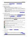
2.1. Start PHOTOMOD StereoDraw module without project
If the main module PHOTOMOD Montage Desktop is opened without any project loaded
(see the corresponding User Manual), you can start PHOTOMOD StereoDraw module from
it without any project too.
This mode allows to load, import, edit and save resources or export any supported data
types, and also to view them in 3D window. The mode is useful when working with data
(vector as a rule), which are out of projects' territory.
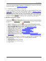
3. Main windows of PHOTOMOD StereoDraw
3.1. 2D window
2D window is a main window used for creating, viewing, and editing of 3D vector objects in
stereo mode. It opens after starting PHOTOMOD StereoDraw with loaded images of
stereopair selected in PHOTOMOD Montage Desktop module or without any stereopair if
the module is opened “without project”. See also chapters 2.1 Start PHOTOMOD
StereoDraw module without project, 6 Creating 3D vector objects and 7 Editing 3D vector
objects. 2D window content is defined in Manager window (see the chapter 4.4 Manager
window).
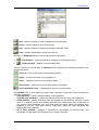
There are the following icons at 2D window button bar:
•
(or F4 hot key) – turns on/off marker = mouse mode (when mouse cursor is not
displayed) and allows to work only with a stereomarker (see the chapter 3.3.3 Marker ==
mouse mode)
5
RACURS Co., Ul. Yaroslavskaya, 13-A, office 15, 129366, Moscow, Russia
PHOTOMOD 4.4
•
- (or F7 hot key) places window center to the marker position
•
(or F6 hot key) – turns on/off fixed marker moving mode, which allows to move the
image “under” the marker located in the center of screen. See the chapter 3.3.2 Fixed
marker mode
•
(or F9 hot key) – turns on/off stereo mode (anaglyph, interlace or page-flipping),
which is selected in system preferences window (opened by menu command Service |
Settings | Stereo). See also the chapter 3.1 Stereomodes
•
- changes the phase of stereoglasses on hardware level. In mono mode, you can
swap left and right images in this window. In stereo mode push this button (or press F11
key) to change stereo mode phase (i.e. also to swap left and right images)
•
(or F2 hot key) - adjusts stereo picture in such a way that the X-parallax for marker is
equal to 0. See the chapter 3.4 Adjusting stereoimage
•
(or F3 hot key) - restores the “depth” of stereo picture (in fact cancels the previous
operation). See the chapter 3.4 Adjusting stereoimage
•
- shows/hides scrollbars
•
- shows/hides panel of brightness, contrast and gamma settings at the bottom of 2D
window which contains appropriate sliders
and contrast adjustment)
•
,
,
(see the chapter 3.8 Brightness
- allows to show / hide the Navigation window, Manager window, see the chapter
3.3 Navigation window and 3.4 Manager) or both of them (Service panel item). To place
the navigation window to the right / left from the view window use option Swap layout
horizontally. You can also place the navigation window upper or lower than Manager by
using Swap layout vertically.
The rest of buttons on 2D window toolbar are intended for image zoom management in the
window, see the chapter 3.1.1 Zooming in / out.
You can hide/show the Objects layer in 2D window by pressing H hot key.
You can work with several 2D windows if necessary. Click the icon
of the main panel or
select the command Windows | New 2D window to open another 2D window. Use the icon
(Arrange windows) to arrange windows on the screen. The icon
is used for
refreshing the windows. Right mouse click on 2D window calls the auxiliary menu duplicating
main menu commands and simplifying operator’s work.
To manage vector objects visualization in 2D window and Navigator use the set of buttons in
the upper button bar as described in the chapter 6.2 Creating vector objects.
3.1.1. Zooming in / out
The following tools of 2D window are used to zoom in / zoom out the image:
•
(hot key “*”) - 1 step zoom in
•
(hot key “/”) - 1 step zoom out
•
(hot keys “Alt-Enter”) - fit image to window
© 2009
6
StereoDraw
•
July 25, 2009
(hot keys “Alt-1”) - 1:1 zoom, when image cell corresponds to screen pixel
For convenient image zooming in 2D window use the following hot keys:
• Alt-2 – zoom 200%
• Alt-3 – zoom 300%
• Alt-4 – zoom 400%
The button
(Preset zoom) is used to zoom the image in 2D window as described in the
chapter 9.1 View settings.
You can also use a slider
for zooming in / zooming out. Move the slider or input
the magnification value in percent from keyboard in this window. Besides, you can zoom in
by zoom box along with pressed Ctrl-Alt-Shift and zoom out by zoom box along with
pressed Ctrl-Alt. For “panning” over the image move a mouse cursor along with pressed Alt
key. See also the chapter 11 Hot keys.
3.1.2. Brightness and contrast adjustment
To change image brightness, contrast and gamma use sliders
bottom of 2D window.
,
,
located at the
A set of buttons located to the right from sliders used for adjustment of image brightness,
contrast and gamma for color channels (red, green, and blue). You can adjust the
parameters either for each selected channel (the button corresponding to the channel color
should be pushed), or for all channels at the same time (when the button
is pushed).
When working in stereo mode (turned on by pushing the button
on 2D window toolbar
or by F9 hotkey) these operations may be performed either for each image of stereopair (to
turn on the right or the left image the button
or
or for the whole stereopair (when the button
is pushed).
correspondingly should by pushed),
To restore default BCG settings select the command Restore settings in context menu of
BCG panel.
These settings are valid only for current session; you should reset them after next
PHOTOMOD StereoDraw opening.
3.1.3. Scrolling and panning
Besides using the standard scroll bars and auto-scrolling mode (when Auto scroll option is
ON, see the chapter 9.2 Edit settings) you can:
• use Pan mode – move the mouse cursor over the image along with pressed Alt key
• load the image screen by screen (with 10 percent of overlap). To pass to the adjacent
screen to the left, right, top or bottom use the Alt key and the corresponding arrow key.
7
RACURS Co., Ul. Yaroslavskaya, 13-A, office 15, 129366, Moscow, Russia
PHOTOMOD 4.4
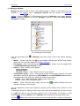
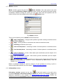
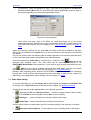
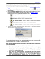
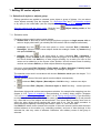
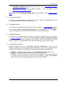
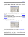
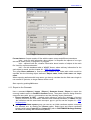
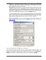
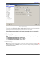
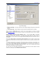
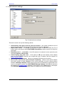
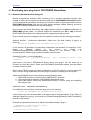
3.1.4. Saving image
You can save the current image shown in 2D window to TIFF format (using menu command
Service | Save image). At that the whole image is saved considering scale and layers
settings in Manager panel.
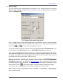
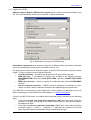
Fig.7 Settings of 2D window image saving
Prior to image saving, setup saving parameters in the window opened. Select preferable
image resolution in dpi or adjust it to achieve needed size of the scene for its printing. Use
the buttons
and
to zoom in/out the image to be saved.
For quick viewing and printing of saved scene use the option Open with RasterView. See
the description of the RasterView window in PHOTOMOD Overview User Manual.
After pushing the Execute button the image will be saved into specified file of TIFF format.
Since the entire image will be saved, not only its current 2D window fragment, you should
remember that images extremely enlarged in 2D window would take quite a long time and
much disk space (but not more than 4 Gb) for saving.
Such image saving is available if GDI graphics mode is selected in PHOTOMOD Montage
Desktop preferences, and anaglyph or interlace stereo mode is selected in PHOTOMOD
StereoDraw settings (see the chapter 9.5 Stereo settings). Turn stereo mode OFF to save
just mono image shown in 2D window. You can save right or left image of stereopair in mono
mode (use the button
in 2D window toolbar to switch between left and right images).
You can also save stereo image if in 2D window anaglyph stereo mode is ON.
Note. Image saving is impossible (menu command is unavailable), if page-flipping
stereo mode is used
© 2009
8
StereoDraw
July 25, 2009
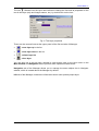
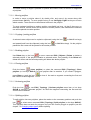
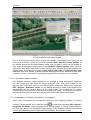
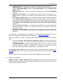
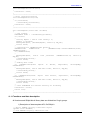
3.2. 3D window
icon of the main panel or by menu command Windows |
3D window (opened by the
New 3D window) is used for viewing of 3D vectors and relief models at different angles in
mono mode. Beside moving and rotating the model you can rescale it by Z-coordinate in
order to view possible erroneous points. The tools of vector vertices editing described in the
chapters 7.3.2.1 Edit vertex and 7.3.2.3 Editing group of vertices are available in both 2D and
3D windows.
Work in 3D window is available if OpenGL interface is using. Refer to the chapter 3.1.2.1
Interlace stereo and also to PHOTOMOD Overview User Manual to get the details about
video adapter adjustment to achieve maximum productivity of photogrammetric processing.
Fig.9 3D window
The following icons at the upper button bar are used to:
•
(hot key “*”) - 1 step zoom in
•
(hot key “/”) - 1 step zoom out
•
(hot keys Alt-Enter) - fit image to window
•
- restore the source zoom level, Z-scale etc.
•
- refresh the 3D window (after making some operations in 2D window)
•
9
,
,
,
,
,
- rotate model in selected direction
RACURS Co., Ul. Yaroslavskaya, 13-A, office 15, 129366, Moscow, Russia
PHOTOMOD 4.4
•
- increase the model scale by Z-coordinate
•
- decrease the model scale by Z-coordinate
•
- increase the model “perspective”
•
- decrease the model “perspective”
•
- save the picture to BMP format
•
- show / hide scroll bars
•
- show / hide Layers panel (see the description below)
To rotate the model in 3D window in different directions you can also use 1, 2, 3, 4, 6, 7, 8, 9
keys of Numpad when NumLock is on. Press 5 key to revert to start model position. Shift“*” and Shift-“/” key combinations are used to increase/decrease model scale by Zcoordinate. To change model “perspective” (move it relatively to the screen plane) use Alt-*
and Alt-/ shortcuts.
At the upper right corner of 3D window there is a Layers panel used to show or hide three
layers: Marker, Raster and Objects. Double click on the icons placed leftwards from the layer
name allows to:
•
- change layer color
•
- show / hide layer
•
•
•
- show layer as solid color, wireframe model or points
- show model in monochrome or by layer-by-layer coloration according to
terrain heights scale
- show texture (none, monochrome, colorful)
Note. If in PHOTOMOD Montage Desktop settings option Epipolar transformation “on
the fly” is ON, raster image will be not visualized in 3D window, see corresponding
User Manual
3.3. Navigation window
Navigation window is located at the upper-right part of 2D window. It shows the full image
of the stereopair and is used for fast moving over it. Click the place on the image in the
navigation window you need and corresponding part of the image will be shown in 2D
window. Green frame in the navigation window bounds the image fragment currently
displayed in 2D window. You can open / close the navigation window by using pop-down
menu opened by the
icon of 2D window. This menu also allows you to swap
navigation, Manager and 2D windows using commands Swap layout horizontally and
Swap layout vertically.
To manage vector objects visualization in 2D window and Navigator use the upper button
bar, described in the chapter 6.2 Creating vector objects.
© 2009
10
StereoDraw
July 25, 2009
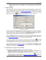
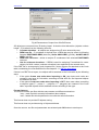
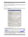
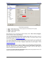
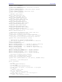
3.4. Manager window
Manager window is used to show / hide different types of objects in 2D window (see the
chapter 4.1 2D window) and in Navigation window (see the chapter 4.3 Navigation
window). Click the
icon of 2D window and select the Manager item to open Manager
window (actually it is open by default). Manager consists of three tabs: Main window,
Navigation and Info.
Fig.10 Manager main window
Click the eye-looking icon
objects:
of Manager main tab to show / hide in 2D window following
•
Marker – double click the icon
to open Marker settings page and to setup marker
shape and color (see the chapter 9.1.2 Marker settings)
• Pre-regions – show / hide pre-regions – vector polygons “drawn” over the images block
in PHOTOMOD Montage Desktop module
• Objects – show / hide 3D vector objects
- Vertex numbers
- Selected objects
- Selected vertices – show / hide vertices of vector objects
• Triangulation points – show / hide ground control and tie points used for the aerial
triangulation and block adjustment in PHOTOMOD AT and PHOTOMOD Solver modules
(see appropriate User Manuals). Additional options are as follows
- Labels – show / hide triangulation points numbers and notes
- Points – show / hide triangulation points
•
Raster – show / hide the raster image. Use the icon
grayscale viewing of color images.
to switch between color and
You can hide/show current layer objects by pressing of the H key when marker is in 2D
window.
To activate the layer for editing click the layer name that causes appearing the pencil image
in it
. After that the layer becomes editable in 2D or 3D window. For instance, to edit
vector objects, activate objects layer in Manager main window by clicking the layer name.
The icon
11
leftward from the layer name is used to change the color of objects of this layer.
RACURS Co., Ul. Yaroslavskaya, 13-A, office 15, 129366, Moscow, Russia
PHOTOMOD 4.4
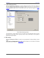
The icon
leftward from the layer name allows to change the font and its properties for the
text in this layer (strip and images names, etc.) by double click on the icon.
Fig.11 Text layer properties
There are also several icons at the upper panel of the first two tabs of Manager:
•
- move layer up in the list
•
- move layer down in the list
•
- refresh layer list
•
- close layer
You can also use a pop-up menu opened by right mouse click on the layer name on the
Main window and Navigation tabs to perform some operations listed above.
Navigation tab of the Manager allows you to manage the same objects but in Navigator
window, which is located above the Manager by default.
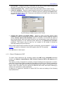
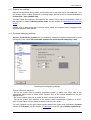
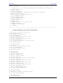
Info tab of the Manager contains the information about each opened project layer.
© 2009
12
StereoDraw
July 25, 2009
Fig.12 Information tab
The icons of the Info tab button bar are used for the following:
•
- refresh the layers list
•
- show information about all layers
•
- hide information about all layers
3.5. Status panel
Status panel (located at the bottom of the module window) is used to display:
• pixel and real (geodetic) marker coordinates (in the right part). See the chapter 4.3.9
Pixel and real coordinates
• error messages. For example, after pressing spacebar to place the marker on the surface
model automatically by the correlator you will get the message Bad point or Ready (see
the chapter 9.3.1 Sound setting and 4.3.4 Snap to ground mode).
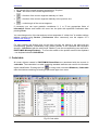
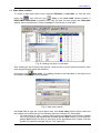
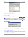
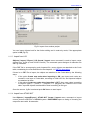
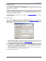
3.6. Object list window
The list of vector objects created in PHOTOMOD project are shown in the Object list
window, opened using the command Windows | Object list or the button
13
.
RACURS Co., Ul. Yaroslavskaya, 13-A, office 15, 129366, Moscow, Russia
PHOTOMOD 4.4
Fig.13 Object selected in Objects list and in 2D window
The window shows objects numbers, their codes, names, types and attributes. If the option
Select object on the image is on, click the object record in the table and the object will be
highlighted in 2D window.
You can save Object list to .dbf file by pushing the button
the window.
, located in the upper part of
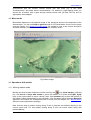
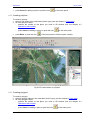
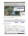
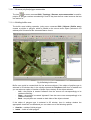
3.7. Raster map window
During stereo vectorization it is not easy to recognize the type of the extracted object if some
of the objects have hidden parts on the image (for example, some part of river in the forest
may be shadowed by trees). In such cases it is better to observe this particular part of the
terrain both on stereopair and on digitized raster map simultaneously. In PHOTOMOD
StereoDraw module there is special window for vectorization control called Raster map.
It is opened by menu command Windows | Raster map or by the button
of main button bar.
(Raster map)
Any georeferenced raster image could be opened in the window in the following formats:
GeoTIFF, ERDAS Imagine, PCIDSK, and also TIFF, BMP, JPEG, NITF, GIF, JPEG2000,
accompanying by georeferencing text files PHOTOMOD GEO, ArcWorld (TFW, BPW,
JPW,…) or MapInfo TAB.
The initial raster image is georeferenced using known ground control points in Georeference
window of PHOTOMOD Montage Desktop module, see an appropriate User Manual.
© 2009
14
StereoDraw
July 25, 2009
Fig.14 Raster map window
In the upper part of the window there is button bar with the following buttons:
- close map
(duplicated by Ctrl-O hot keys) - open raster map – opens file selecting dialogue. If the
map to be opened is not located within the stereopair you will get a warning
(duplicated by F5 hot key) - refresh vectors – synchronize vectors on the raster map
and stereopair
(duplicated by / hot key) - zoom out
(duplicated by Alt-1 hot keys) - 1:1 zoom, when image cell corresponds to screen pixel
(duplicated by * hot key) - zoom in
(duplicated by Alt-Enter hot keys) - fit to page
- zoom scale
- relative thickness of the vector objects – the field is used for vector lines
thickness changing. The value in this field is a coefficient by which absolute object thickness
taken from Code table is multiplied. Color and thickness of vectors shown on the raster map
are taken from Code table
- show vectors – to view vector objects (opened in 2D window) with raster map in
background
- grayscale – transfer color raster image into grayscale
- no raster – closes raster image but preserves vector objects if any
- synchronize windows – synchronizes marker movement in 2D window and raster
image window. At that when marker is moving in one of these windows it is moving in
another too.
15
RACURS Co., Ul. Yaroslavskaya, 13-A, office 15, 129366, Moscow, Russia
PHOTOMOD 4.4
In most cases stereopair orientation is not the same as coordinate system orientation (on
raster map). That is why for more convenient work the map could be rotated in the following
ways:
- without rotation,
- turn at 90 degrees,
- turn at 180 degrees and
turn at 270 degrees. At that raster file is not changed and the rotation is executed “on the fly”.
All view settings, path to loaded map, and also Raster window visibility, size and location are
saved automatically and restore at next PHOTOMOD StereoDraw session. At that map file
name is associated with stereopair name and thus different stereopairs will be opened with
appropriate raster maps.
4. Stereo viewing and measuring
4.1. Stereomodes
To switch between stereomodes, described below use Service | Preferences | Stereo
menu. To turn ON/OFF stereomode in 2D window click the icon
in upper menu of 2D
window or F9 hot key. Stereo mode type is set in PHOTOMOD StereoDraw module settings
page (see the chapter 9.5 Stereo settings). See the details on hardware settings of your PC
for convenient working in stereomode in PHOTOMOD Overview.
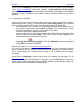
4.1.1. Anaglyph glasses
Anaglyph stereoimage is formed by visualization of the left and right images of the stereopair
“beyond” red and blue filters. To view such a picture you should use special anaglyph
spectacles with red and blue glasses. Anaglyph stereomode requires no special equipment
but it is not completely good for working with color images. Another disadvantage is that the
picture gets a bit darker when viewing through filters. See also the chapter 4.1.2 Shutter
glasses.
Note. Anaglyph stereo is available only for HighColor or TrueColor display mode of
your monitor
© 2009
16
StereoDraw
July 25, 2009
Fig.1 Anaglyph stereoimage
4.1.2. Shutter glasses
Shutter glasses are liquid crystal glasses synchronized with the vertical refresh rate of the
monitor. PHOTOMOD system supports two modes of working with shutter glasses: interlace
and page-flipping (see the chapters 3.1.2.1 Interlace stereo and 3.1.2.2 Page-flipping
stereo). Refer to PHOTOMOD Overview for the details about using of stereo glasses and
other special equipment for images stereo processing.
4.1.2.1. Interlace stereo
Interlace (“line by line”) display mode divides the display frame into two semi-frames. The
first one contains odd lines and the second one contains even lines. Right and left images of
the stereopair are displayed one by one in ”odd” and “even” frames. The shutter glasses are
synchronized with the monitor vertical refresh rate and allow you to see them
“simultaneously” and make stereo measurements. The interlace mode may be applied only
for the whole screen, so it introduces some inconvenience when working with menus.
Another disadvantage is sampling picture and, thus, reducing its resolution because of using
semi-frames. The comfortable vertical refresh rate of your monitor should be at least 75 Hz
“for each eye” (150 Hz for interlace mode).
4.1.2.2. Page flipping stereo
Page flipping (“frame by frame”) display mode provides the most high quality stereo picture
because it uses full frames instead of semi-frames. Left and right images of the stereopair
are displayed one by one synchronously with the frames switching. The shutter glasses are
17
RACURS Co., Ul. Yaroslavskaya, 13-A, office 15, 129366, Moscow, Russia
PHOTOMOD 4.4
synchronized with the monitor vertical refresh rate and allow you to see them
“simultaneously” and make stereo measurements. For working in page-flipping mode you
should use a monitor with a good enough vertical refresh rate (at least 120 Hz) and an
appropriate video adapter.
4.2. Mono mode
Monomode displays the left epipolar image of the stereopair and the left component of the
stereomarker. You can use Snap to ground mode for 3D vectorization over the mono image
(see the chapter 4.3.4 Snap to ground mode). All created in such a way vectors should be
checked manually in stereomode to avoid possible correlator errors.
Fig.2 Mono image
4.3. Operations with marker
4.3.1. Moving marker mode
icon (fixed marker) or F6 hot
Moving and fixed marker modes are turned on/off by the
key. Use mouse or keys with arrows to move the marker in XY plane and PgDn, PgUp
keys or the mouse wheel to move it along Z axis. Use spacebar key to place the marker on
the model surface automatically by the correlator. If the correlator fails a message Bad point
appears in the Status bar accompanied with a sound (see the chapter 9.3.1 Sound setting
about the sound parameters settings).
Note that the step of marker moving along Z axis is discrete and defined directly by the
current zoom level. For fast marker moving along Z axis use mouse wheel along with
pressed Alt key.
© 2009
18
StereoDraw
July 25, 2009
You can also turn ON/OFF a “rubber line” which accompanies marker on the screen during
stereo vectorization using R hot key. You can change color of the last and next to last
segments of rubber line in module settings (Service | Settings menu command), see the
chapter 9.1.3 Rubber line settings.
You can change marker shape, using Marker page on module settings page (opened by
Service | Settings menu command), see the chapter 9.1.2 Marker settings.
4.3.2. Fixed marker mode
icon (fixed marker) or F6 hot
Moving and fixed marker modes are turned on/off by the
key. In case of fixed marker the marker is always located in the center of screen and its X
parallax is equal to 0.
During vectorization you move the images of stereopairs by the mouse or arrow keys (←, ↑,
→, ↓) in plane and by PgDn, PgUp keys or the mouse wheel by Z. Use spacebar key to
place the marker on the model surface automatically by the correlator. If the correlator fails a
message Bad point appears in the Status bar accompanied with a sound (see the chapter
9.3.1 Sound setting about the sound parameters settings). In case of fixed marker the step of
moving the model by Z coordinate is defined by the user (see the chapter 9.3.1 Sound
setting).
This mode is familiar for operators experienced in working with analytical stereo devices.
Another advantage is a smooth roam vectorization with a constant image auto scrolling.
You can change marker shape, using Marker page in module settings (Service | Settings
menu command), see the chapter 9.1.2 Marker settings.
4.3.3. Marker == mouse mode
This mode (turned on by clicking the icon
marker == mouse or F4 hot key) “removes”
mouse cursor from the screen. In this case any mouse movement causes the corresponding
stereomarker moving without mouse click. The mode is useful for digitizing polylines and
polygons. You can change marker shape, using Marker page in module settings (Service |
Settings menu command), see the chapter 9.1.2 Marker settings.
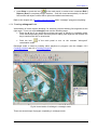
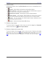
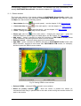
4.3.4. Snap to ground mode
or T hot key) is used for
Snap to ground mode (turned on by clicking the icon
automatic “placing” the marker on the model surface using the correlator (see the chapter 9.3
Correlator parameters). So you can move the marker in XY plane manually by the mouse
and it will change Z coordinate automatically in accordance with the terrain relief. If the
correlator fails a message Bad point appears in the Status bar accompanied with a sound
(see the chapter 9.3.1 Sound setting about the sound parameters settings). In this case you
can place the marker manually by PgUp, PgDn keys or the mouse wheel. The mode is
extremely useful for the vectorization.
19
RACURS Co., Ul. Yaroslavskaya, 13-A, office 15, 129366, Moscow, Russia
PHOTOMOD 4.4
Fig.3 Vectorization in snap-to-ground mode
4.3.5. Stream line mode
You can extract terrain features in 2D window using stream line mode – drawing the
continuous line by mouse with pressed left button. To turn on such vectorization mode push
the icon
(Stream-line) of upper button bar or press Y key, and place the first line point
by Insert key. At that in code table you should select line (L) or polygon (P) object type (see
the chapter 5 Code table). Stream line mode allows you to select the distance between
digitized points in meters on the terrain or image pixels, using an appropriate option in
module settings, see the chapter 9.2 Edit settings.
Release the icon
or press the key Y again to quit the stream line mode.
Note. Use Ctrl-H hot keys to turn off/on the marker (showed by white oblique cross)
during vectorization in stream-line mode
4.3.6. Fixed Z mode
If you need to draw a vector line at a constant Z level use Fixed Z mode. To set a Z value,
place the marker to a correct position and select menu command Edit | Fix marker by Z or
press Alt-Z shortcut or click the icon
in the Marker window opened by the icon
of
the main panel or by the command Windows | Marker window. You can also enter the Z
value in Z field of Marker window. See the chapter 4.3.7 Marker window. Release the above
mentioned icon or menu option to quit this vectorization mode.
© 2009
20
StereoDraw
July 25, 2009
4.3.7. Marker window
Marker window of the main panel or by main
Marker window (opened by the icon
menu command Windows | Marker window) shows current real (ground) and pixel marker
coordinates. Besides viewing the values you can enter them from the keyboard and the
marker will be moved accordingly after pushing the
Apply button.
Fig.4 Marker window
There are the following icons at Marker window button bar:
•
- apply immediately – change marker position right after entering coordinate values
without pressing Enter key
•
- apply – moving marker in accordance with entered coordinate values
•
- canceling coordinate values input
•
- more decimal places – increasing number of decimal places in coordinate values
at 1
•
- less decimal places – decreasing number of decimal places in coordinate values
at 1
•
- pixel coordinates – to show / hide marker pixel coordinates (see the chapter 4.3.9
Pixel and real coordinates)
•
- real coordinates – to show / hide marker ground coordinates (see the chapter
4.3.9 Pixel and real coordinates)
•
- fix marker by Z – in this case there is no way to move marker along Z axis (used
for objects vectorization at constant Z level). Duplicated by Alt-Z shortcut. See the
chapter 4.3.5 Fixed Z mode.
Marker coordinates entering is used for instance, for the operation of moving a point or
vertex to the marker position (see the chapter 7 Editing 3D vector objects).
4.3.8. Information window
of the main panel or by main menu
Information window (opened by the icon
command Windows | Information window) displays the values of coordinates, angles and
distances described in the chapter 4.5 Measurements over the model. Beside the
measurements mode Information window is used also during 3D vectorization.
21
RACURS Co., Ul. Yaroslavskaya, 13-A, office 15, 129366, Moscow, Russia
PHOTOMOD 4.4
Fig.5 Information window
If necessary you can input geodetic coordinates X, Y or Z into appropriate fields of
Information window and marker will move into the point with specified coordinates after
pressing Enter.
4.3.9. Pixel and real coordinates
PHOTOMOD StereoDraw supports two modes of marker moving – real coordinates and
pixel coordinates.
•
•
Real coordinates (the default mode) – when marker is moving in the image plane, its
real (ground) X, Y coordinates are changing while Z coordinate remains the same. When
the marker moves along Z coordinate its real X, Y coordinates remain the same.
Pixel coordinates – marker is moving in the “pixel” space. This means that when the
marker is moving in the image plane its image (pixel) Xp, Yp coordinates are changing on
the left image while the X parallax keeps the same. In case of movement of the marker
along the “depth”, its X parallax is changing and, hence, Xp in the right image is changing
correspondingly, while the marker Xp, Yp coordinates in the left image keep their values.
This mode of the marker movement is convenient in case of close range survey when the
ground coordinate system is oriented relatively to the image plane in a quite different way
than in the case of usual airborne images.
Pixel and real coordinate values are displayed in Status panel (located at the bottom of the
screen). To switch between marker coordinate units use corresponding buttons with arrows
in Status panel (see the chapter 3.5 Status panel).
Marker window also displays real and pixel marker coordinates (see the chapter 4.3.7
Marker window).
4.3.10. Types of snapping
When working in the snap mode the marker is moved only along the existing vector objects
(points, vertices or segments). It is useful when you need to create an object that spatially
coincides with some existing objects. For example when you vectorize electric power line
connecting existing piers (point objects). PHOTOMOD StereoDraw provides the following
types of snapping:
• 3D snapping to vertex (the
icon or V hot key). In this mode the marker “jumps” from
one vertex to another. When you click somewhere on the image, the marker moves to the
nearest vertex or point.
© 2009
22
StereoDraw
July 25, 2009
• 2D snapping to vertex (the
icon or B hot key). In this mode the marker “jumps” from
one vertex to another and XY marker coordinates coincide with XY coordinates of the
vertex. Marker Z coordinate at that will be preserved.
• 3D snapping to line (the
icon or N hot key). In this mode the marker moves along
existing vector objects lines (segments) keeping all XYZ coordinates. When you click
somewhere on the image, the marker moves to the nearest vector object.
• 2D snapping to line (the
icon or M hot key). In this mode the marker moves along
existing vector objects lines (segments) just in XY plane. Marker Z coordinate at that will
be preserved.
2D snapping is used when the creating object must spatially coincide with an existing one
only in XY plane. For example you want to “draw” an extension to some building at the other
Z level.
Hot keys listed above are used for quick setting snapping on (the key is pressed down) and
off (the key is released).
Note. 2D snapping result depends on current marker movement mode (pixel or
geodetic coordinates). See the chapter 4.3.9 Pixel and real coordinates
When creating an object in the snapping mode you can include a part of some existing object
into the object that is currently being created. As a result, two or more vector objects will
have common part. But unlike the operations Auto-continue along polyline or Closing along
polyline these “shared” parts of different objects exist separately. For example, you can
change vertices of one of the objects, while the other objects don’t get any changes.
You can create common vertices of two objects in 2D or 3D snapping to line mode, using
Alt-V shortcut.
Note. For searching of the nearest point in the snapping mode, the 2D image pixel
coordinates are used
Note. Both editable and reference objects (see the chapter 6.3 Reference layers) could
be used for snapping
4.4. Adjusting stereoimage
No matter which kind of stereomode you use, you need to adjust the stereo image to get the
best stereo effect in some particular image region. This is especially important when you
work with “deep” images, i.e. those having big variations in X parallax. To adjust the stereo
image, do the following:
• place the stereo marker on some point of the region of interest manually or by snap to
ground operation (see chapter 4.3 Operations with marker);
• press F2 key or click the
icon of 2D window.
The program will rebuild the stereo image to set X parallax in the point of stereo marker to
zero value. So the best stereo picture is in the area around the marker.
Press F3 key or click the
icon of the main panel to restore the stereo depth.
You can change stereomode phase (i.e. swap over left and right images) using F11 key or
the button
23
in 2D window.
RACURS Co., Ul. Yaroslavskaya, 13-A, office 15, 129366, Moscow, Russia
PHOTOMOD 4.4
Besides, you can use Shift-PgUp/PgDn or Shift-mouse wheel shortcuts to change stereo
image deepness. See also the chapter 11 Hot keys.
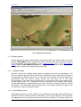
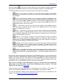
4.5. Measurements over the model
of the main panel or by
The mode of measurements (turned on by pushing the icon
selecting menu item Edit | Measure mode) is useful for some temporary stereomeasurements – when for example you need to know the height of a building or a tree.
There are exactly the same tools as for the 3D line creation – Insert key to add a vertex,
PgUp, PgDn keys or mouse wheel to move marker by Z and the mouse or arrow keys to
move marker in plane. The line appeared is a temporal one: it disappears after you quit
measurements mode (by releasing the same icon
or turning off the menu item).
Fig.6 Measurements over the model (anaglyph stereoimage)
Measurements window displays the following values:
• X – marker X geodetic coordinate
• Y – marker Y geodetic coordinate
• Z – marker Z geodetic coordinate
• Xp – marker geodetic X-coordinate in previous point
• Yp – marker geodetic Y-coordinate in previous point
• Zp – marker geodetic Z-coordinate in previous point
• dX – marker geodetic delta X when drawing a “rubber line”
• dY – marker geodetic delta Y when drawing a “rubber line”
• dZ – marker geodetic delta Z when drawing a “rubber line”
• S – length of the current segment of the “rubber line”
© 2009
24
StereoDraw
•
•
July 25, 2009
D – length of the current segment projection on XY plane
dZ/D – the value of the current segment slope
•
– direction of the current segment relatively to X axis
•
– direction of the current segment relatively to the previous one
•
– vertical angle of the current segment
If necessary you can input geodetic coordinates X, Y or Z into appropriate fields of
Information window and marker will move into the point with specified coordinates after
pressing Enter.
You can change color of the last and next to last segments of “rubber line” in module settings
window (opened using Service | Preferences menu command), see the chapter 9.1.3
Rubber line settings.
For easy viewing and finding point on the block (moving the marker to the point with the
corresponding geodetic coordinates) copy marker position to the clipboard with keyboard
shortcut - Ctrl-Alt-Ins (with the active layer "Marker") (see the corresponding user manual for
PHOTOMOD Montage Desktop) . To move the marker to the position saved in the clipboard
- use keyboard shortcut Shift-Alt-Ins.
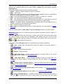
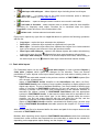
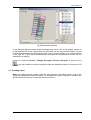
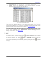
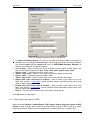
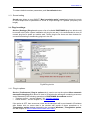
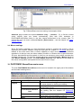
5. Code table
All vector objects created in PHOTOMOD StereoDraw are associated with the records in
code table. The code table is a table containing standard attributes set used for the thematic
object classification. Pushing the icon
or using menu command Windows | Code table
calls the window containing left and right parts and upper icon menu.
Fig.15 Code table
25
RACURS Co., Ul. Yaroslavskaya, 13-A, office 15, 129366, Moscow, Russia
PHOTOMOD 4.4
There is a list of thematic layers of the current project in the left part of the window. The right
window part contains codes list of vector objects (Codes tab) and objects attributes
(Attributes tab).
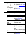
Codes tab contains the table with the following columns:
• Visible – visibility of objects with given code in 2D window
• Code – object code
• Name – the unique text string up to 64-character length created to refer to a vector object
or group of vector objects. For example “Unpaved road”
• Type – one of the following types of an object: P – point, L – polyline, C – polygon
• Color – the color used to show the object on the raster image
• Size – the floating point number that determines the size of a vector object in ground
units. For points this feature controls the size of the symbol on a raster image;
• Symbol – the ASCII symbol, corresponding to the object code (for point objects only), it
could be selected from the standard symbol library
• Q-ty – quantity of objects of given code
• Attr. – option of availability and number of object attributes (see the chapter 5.4 Adding
attributes)
Click the column header in Code, Name, Type and Quantity columns to sort the objects.
Attributes tab allows you to create and edit the attribute information (see the chapter 5.4
Adding attributes).
If the icon
leftward from the name layer or object code is active, then vector objects with
this code or located on this layer are displayed in 2D window. And you can turn on/off
visibility of the selected objects or layers in 2D window using click on this icon (or the icons
and
, located above the layers list).
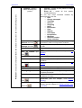
Upper icons of the Code table window are intended for the following operations:
•
- new – creates new code table after closing the loaded one (see the chapter 5.1
Code table creation)
•
- open – opens existing code table
•
- save as – saves changes
•
- code table import – opens standard dialogue for import codes to the current
Code table (see the chapter 5.3 Code table import)
•
- code table export – opens standard dialogue to input file name (with *.rsc
extension) for export codes to VectOr format (see also the chapter 8.2.9 Export to
VectOr)
•
- assign code to selected objects – allows to change the code of the objects
selected in 2D window (see the chapter 5.7 Attaching vector objects to the code table
and 7.5 Changing object types)
•
- select all objects with current code (see the chapter 7.1.4 Selection of objects
with the same code)
•
- select all group objects (see the chapter 7.1.3 Selection of layer objects)
•
- select all visible objects – if visibility of some objects is OFF (by mouse click on
the “eye”
© 2009
icon rightward from code or layer name) you can select the rest visible
26
StereoDraw
July 25, 2009
objects using this button. Use such selection to export a group of all selected objects
using menu command Objects | Import/Export | Format | Export selected objects
•
- show selected object code – allows to show object code in Code table when an
appropriate vector object is selected in 2D window
•
- show selected code – used to scroll down the list of codes in Code table in such
a way that the code of the object selected in 2D window is shown in the Code table. This
operation is useful when selected code is at the bottom of the long Code table list and is
invisible without scrolling down the list
•
- set label for current code (see the chapter 5.6 Labels creating)
•
- set label for all group codes (see the chapter 5.6 Labels creating)
•
- assign elevation from attribute to selected code – if after vector objects import
their heights are located in Code table attributes, you can assign these heights to object
vertices, by pushing this button. The operation is used during contours import from
MIF/MID and SIT (Map 2005, VectOr) formats
•
- assign elevation from attribute to selected layer – if after vector objects import
their heights are located in Code table attributes, you can assign these heights to vertices
of all objects in selected layer, by pushing this button. The operation is used during
contours import from MIF/MID and SIT (Map 2005, VectOr) formats
•
- show codes from sublayers – if pushed and some layer in Layers list is selected
then all vector objects codes available on this layer is shown in codes list
•
- edit code… – opens a window for editing selected code or attribute (see the
chapter 5.2 Code table editing)
•
- add code… – opens a window for new code or attribute creation (see the chapter
5.2 Code table editing)
•
- add code to favorites – adds selected code to another codes list, which simplifies
searching for frequently used codes. Favorites list is visualized when the option
Favorites in lower left corner of the Codes table is ON
•
- delete – allows to delete selected code or attribute after some warning
•
- select hot key for current code – opens an additional window which allows to
associate chosen hot key (Shift-1,2,3,4,5) to the current vector object code, that makes
easy quick code call in the Code table
•
- find text – opens a window of searching record in selected mode: By code, By
code name. Type the value you need in the selected text field and push OK to start the
search
•
- search again – further code search in selected mode
•
- close – closes code table window
The code table is a useful tool for vector objects classification. For example you can select
objects with the same code and delete them or show them with some particular color. Vector
objects codes are using also for vectors export to exchange formats, see the chapter 8.2
Export.
27
RACURS Co., Ul. Yaroslavskaya, 13-A, office 15, 129366, Moscow, Russia
PHOTOMOD 4.4
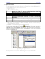
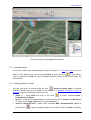
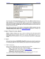
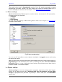
5.1. Code table creation
To create a code table select menu command Windows | Code table (or click the main
panel icon
), then click the icon
(New) in the Code table window opened. If
PHOTOMOD StereoDraw is started for the very first time for some project the Code table
window opens automatically. Create new Layer in the left part of code table.
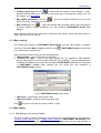
Fig.16 Creating new layer in code table
After creating the list of layers of the objects, create the list of vector objects included to each
layer along with their codes and attributes.
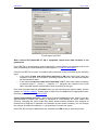
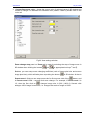
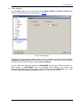
Pushing the icon
(Add code…) for adding records to the code table (in the right part of
the window) opens the following dialogue:
Fig.17 New code creation
Use Code field to input the unique object code, then Code name field for object name and
also assign to the object its type and following features to display it in 2D window:
• For point object (P type) – symbol (from popped up standard symbol library) symbol
color (from popping up standard MS Windows palette (Win button) or from AutoCAD
palette (ACI button)) and size (in point units in the appropriate field). Please note that
symbol size could be changed only for True Type fonts.
© 2009
28
StereoDraw
•
July 25, 2009
For polyline (L type) and polygon (С type) – line color (from popped up standard MS
Windows palette (Win button) or from AutoCAD palette (ACI button)) and its style in
the window appearing by pushing the appropriate button:
Fig.18 Line style selection
Here select line type, style of its filling, its width and shape of its end using
appropriate options. Selected line style is preserved during line objects export into
DXF and DGN formats, see the chapters 8.2.3 Export to DXF and 8.2.4 Export to
DGN.
When all necessary options are set, push OK and object code will be added to the layer
which name is selected in the Layers list or to the root directory if the objects are not divided
into layers.
So you can create codes for different objects which supposed to be extracted and add them
to the Code table with possible classification into thematic layers.
Once the hierarchical Code table is created save it using the icon
(Save as) to the
resource with specified name. The code table will be opened automatically for all
PHOTOMOD StereoDraw further sessions. If you need to open another code table click the
icon
(Open) to get a list of available resources with code tables. Also you can create
new code table using an imported one (see the chapter 5.3 Code table import).
Besides, while importing vector objects to PHOTOMOD StereoDraw module from exchange
formats their codes could be also imported into new code table or added to the existed one
depending on the appropriate option setting, see the chapter 8.1 Import.
5.2. Code table editing
In current code table you can edit Layers list in the left panel and Codes and attributes list
in the right one. Layers list editing is described in the chapter 5.4 Attributes creation.
Use the button bar above the Layers list for the following operations:
•
(duplicated by F2 key) edit layer name… – allows to change selected layer (folder)
name. Press Enter to save changed name or Esc to cancel editing
•
add layer… – opens a window for new layer (folder) name input
•
delete layer – deletes selected layer (folder) from Layers list
Use the same buttons of upper button bar for Code table editing in the right part of window:
•
29
show layer with sublayers – shows objects in layer including those in sub-layers
RACURS Co., Ul. Yaroslavskaya, 13-A, office 15, 129366, Moscow, Russia
PHOTOMOD 4.4
•
hide layer with sublayers – hides objects in layer including those in sub-layers
•
edit code… – (or double click on the code record selected) opens a dialogue
described in the chapter 5.1 Code table creation
•
•
add code… – opens a dialogue used to create a new record in code table
add code to favorites – adds selected code to another codes list that simplifies
searching for frequently used codes. Favorites list is visualized when the option
Favorites in lower left corner of the Codes table is ON
•
delete code – deletes selected code table record
Popup menu opened by right click on Layer list allows to perform the following operations
with the list:
•
•
•
•
Copy layer – copies the layer selected to the clipboard
Paste layer – pastes the layer copied from clipboard into Layers list
Move layer – moves the layer taken from clipboard into Layers list or inside selected
layer (as a sublayer) and removes it from the previous location
Show layer with sublayers – opens in 2D window objects with codes, which belong
•
to the active layer (the icon
leftwards from layer name becomes active at that)
Hide layer with sublayers – hides in 2D window objects with codes, which belong to
the active layer (the icon
leftwards from layer name becomes inactive at that).
5.3. Code table import
For Code table import use the icon
(Code table import) or menu command Objects |
Code table | Import, which opens the dialogue for file selection. There are several
possibilities of vector objects codes import when creating the code table or adding codes to
the current one:
- import of the code table created in the previous versions of PHOTOMOD system (files
with .ctb and .ctf extensions)
- import of PHOTOMOD VectOr classifier to the StereoDraw code table (.rsc files).
PHOTOMOD VectOr uses a library of map symbols (classifier) to display and print out
digital map objects. The set of standard classifiers (.rsc files) related to different map
scales is included to PHOTOMOD distribution file set and stored in \VectOr\RSC
directory by default. Use the table code corresponding to the classifier selected to
associate the objects created in PHOTOMOD StereoDraw with the appropriate
symbols in PHOTOMOD VectOr. In that case the table code will be equivalent to the
classifier code for the exact object type. In the dialog opened select the source
classifier (.rsc file) and output resource with the code table file (.ctb file), and the
system will create the code table based on the selected map classifier.
- import of PHOTOMOD VectOr classifier, associated with existing map (.sit and .map
files) to PHOTOMOD StereoDraw code table (see also the chapter 8.1.10 Import from
VectOr).
After selecting the file to be imported define the name and path for the output resource with
code table in PHOTOMOD format.
Besides, while importing vector objects to PHOTOMOD StereoDraw module from exchange
formats their codes could be also imported into new code table or added to the existed one
depending on the appropriate option setting, see the chapter 8.1 Import.
© 2009
30
StereoDraw
July 25, 2009
5.4. Attributes creation
For each vector object code you can add some auxiliary attributes using the Attributes tab in
the Code table window with the following parameters:
• Name – field name
• Type – field type (see below)
Text
Integer
Smallint
Decimal
Float
Data
Logical
•
•
- text attribute either without parameters (in this case the length of the
attribute is the length of its value, but not greater than 32767) or with one
parameter, specifying the fixed length of the text;
- 4 byte integer (without parameters);
- 2 byte integer (without parameters);
- fixed decimal point attribute with two parameters. The first parameter is the
total attribute length in bytes, the second - the number of digits after the
decimal point;
8 bytes float attribute (without parameters);
unformatted attribute with one parameter specifying the attribute length in
bytes;
logical attribute with possible values 0 or 1 (without parameters).
Size (bytes) – for numeric fields is defined automatically, otherwise should be defined by
user (for text fields for example)
Precision – number of decimal places for “float” attributes
To edit or create attribute table click the icon
(Edit attribute) of the upper button bar in
Code table window, when Attributes tab is selected. After that you will get the window for
editing the parameters of attributes of record selected. Besides you can use the following
operations on Attributes tab:
Fig.19 Adding the object’s attribute
To assign attribute value to attribute with integer type use the panel Values list.
31
RACURS Co., Ul. Yaroslavskaya, 13-A, office 15, 129366, Moscow, Russia
PHOTOMOD 4.4
- add – opens a window for input of attribute name and value
- delete – deletes attribute value from the list
- edit – opens a window for editing of attribute name and value
- clear – deletes all attributes values from the list.
Besides, on Attributes tab you can use the following operations:
•
- add attribute – opens a window for creating a new attribute record
•
- delete attribute – deletes current attribute field
Use the buttons on the left side of Attributes tab to perform the following operations with
object’s attributes:
- move up – moves the record to the topmost position
- upper – moves the record on one position up
- lower – moves the record on one position down
- move down – moves the record to the bottommost position
- invert attributes order – rearranges the list in the reverse order.
On Attributes tab of code table use popup menu opened by right click, which contains the
following commands:
▪ Copy attribute – copies selected attribute to the clipboard
▪ Copy all code attributes – copies all attributes of the current code to the clipboard
▪ Paste attribute – pastes attribute(s) from the clipboard to the attributes list of the current
code. It is used to remove unnecessary attributes from other codes of the Code table. If
you need to move attributes from one Code table to another, paste the attribute from
clipboard to text file. Then open another Code table, select the code and paste the
attribute into code selected.
▪ Get Z from attribute – assigns Z coordinate to the objects of selected code. The
coordinate is either taken from imported file or input by the user.
© 2009
32
StereoDraw
July 25, 2009
To enter the attribute values push the icon
of main menu or use the command
Windows | Objects attributes. Select Attributes tab in the Object attributes window
appeared and enter attribute values in the Values column after clicking the grey field.
Fig.20 Vector object attributes
To start editing the attribute value in table cell, select it by mouse and press F2. To complete
editing and save the input value, press Enter or just click the next cell with attribute value.
Press Esc to cancel editing and exit.
The following operations are available for attribute’s values:
• Copy to clipboard – allows to copy attribute’s values of the object to the clipboard using
menu command Edit | Objects | Copy attributes values if the object is selected in the
current layer
• Paste from clipboard – object’s attribute value, which was copied to the clipboard by
previous operation, could be assigned to the one or several selected objects of active
vector layer. Use menu command Edit | Objects | Paste attributes values to add
attribute’s values to the attributes with the same names.
In Object attributes window you can create an additional attributes for the objects selected,
using Additional attributes tab (see the chapter 5.5 Additional attributes).
5.5. Additional attributes
Besides the attributes associated with a code in the code table (see the chapter 5.4
Attributes creation) the unique attributes for the selected object could be created. At that all
objects associated with some code in the code table will have common attributes defined in
33
RACURS Co., Ul. Yaroslavskaya, 13-A, office 15, 129366, Moscow, Russia
PHOTOMOD 4.4
the code table, but each of them may have some additional unique attributes. To create a
table of additional attributes you should do the following:
• select vector object or group of objects (see the chapter 7.1 Selection of object or objects
group)
•
•
on the main
select menu command Windows | Object attributes or push the icon
menu. First two tabs of Object attributes window show a record in the code table and
object attributes
select the Additional attributes tab and create a table of additional attributes in exactly
the same way as for code tables attributes (see the chapter 5.4 Attributes creation).
Following icons are used to create additional attributes table:
- delete all additional attributes for selected objects – deletes all
additional attributes for selected objects
- delete same additional attributes for selected objects – deletes
additional attributes which are common for selected objects
- add additional attribute – opens a window for creating a new additional
attribute
- delete additional attribute – deletes current additional attribute
- edit additional attribute – opens a window for editing current additional
attribute
select the fields by the mouse and enter the attribute values to associate the additional
attributes with the selected vector object.
•
Fig.21 Additional attributes
To start editing of the additional attribute value in table cell, select it by mouse and press F2.
To complete editing and save the input value press Enter or just click the next cell with
additional attribute value. Press Esc to cancel editing and exit.
Note. Additional attributes could not be exported in PHOTOMOD VectOr module unlike
usual object attributes
You can perform the following operations with objects with additional attributes:
• Select objects with additional attributes – the command allows to select those
objects of vector layer that have an additional attributes, using menu command Edit |
Objects | Select objects with additional attributes. This operation is useful to
select the objects with additional attributes, which may lie for example out of visible
stereopair, and delete them afterwards.
• Select objects with additional attribute, using search by name of the additional
attribute – the operation allows to select those objects of vector layer that have an
additional attribute with user defined name. Use menu command Edit | Objects |
Select objects with additional attributes, which calls the window of additional
© 2009
34
StereoDraw
July 25, 2009
attribute search by name. This operation is useful to select the objects with additional
attributes, which may lie for example out of visible stereopair, and delete them
afterwards.
5.6. Labels creating
Each vector object could be supplied with special sign (label) displayed in 2D window as a
label to the point object or to the linear object vertex (if the appropriate option in module
settings is ON, see the chapter 9.1.4 Labels displaying settings). This label could be also
exported to DXF file of AutoCAD system. To assign the label, select object code in Code
table and push the icon
(set label for current code) in the upper button bar.
Fig.22 Label creation
In the list appeared choose the label source (taken from the values of columns of the layer
selected in codes list). If Attribute value is selected, Attributes pop down list is available to
select the label content, which will be visualized in PHOTOMOD StereoDraw 2D window or
AutoCAD program after export of the objects of selected code to DXF file.
Push the Parameters button in this window to open the window with Labels settings and
change other settings of vectors labels (font size and label location), refer to the chapter
9.1.4 Labels displaying settings for more details about labels settings.
If you need to assign a label to all objects of selected layer push the button
(set label
for all group codes). At that the label is assigned to all objects in selected layer, that is why
you should assign it only after creation of all layer objects just prior their export to DXF.
After vector objects export to DXF format (menu command Objects | Import-Export | DXF
format, see the chapter 8.2.3 Export to DXF) and opening this layer in AutoCAD system
these objects will be shown with label assigned.
5.7. Attaching vector objects to the code table
The code table records may be attached to vector objects in two ways:
• while the vector object creating. Select the record you need in the Code table window
and start the vectorization. The code will be assigned automatically
• attaching record to an existing object. Select an object or a group of objects in 2D
window and code to be assigned in the Code table and click the icon
(assign code
to selected objects). See the chapter 7.1 Selection of object or objects group.
35
RACURS Co., Ul. Yaroslavskaya, 13-A, office 15, 129366, Moscow, Russia
PHOTOMOD 4.4
See also the chapter 6 Creating vector objects and 7.5 Changing objects types.
6. Creating 3D vector objects
6.1. Types of vector objects
PHOTOMOD StereoDraw works with 3D vector objects of the following types:
• point – a point in space, defined by X, Y, Z coordinates
• polyline – a set of XYZ points (vertices) connected by straight lines (segments). The
polyline may be either closed or unclosed. In case of closed polyline its first and last
vertices are spatially coinciding
• polygon – a closed polyline. The polygon is closed automatically after finishing its
creation. During polygon creation its first and last vertices are coincide spatially and are
edited simultaneously.
• CAD objects – standard geometric figures, see the chapter 6.2.5 Creating CAD-objects.
6.2. Creating vector objects
All marker related operations, described in the chapter 3.3 Operations with marker are used
during vector objects creation. Especially useful modes are Snap to ground and Snapping
(see the chapters 3.3.4 Snap to ground mode and 3.3.9 Types of snapping). To start vector
objects creation click icon
(Object editing mode) of the main panel.
Note: In order to increase the vectorization productivity, use special 3D or multibutton
mice, hand wheels and pedals as well as programming of ordinary mouse buttons for
different operations (see the chapter 9.8 Mouse settings)
The following set of buttons in upper button bar is used to manage vector objects
visualization in 2D window and Navigator:
- show objects – turns on/off vector objects view in 2D window and Navigator
- show vertices – turns on/off vertices of vector objects view in 2D window, i.e. allows
to edit only line segments vertices without vertices viewing
- show lines – turns on/off line segments of vector objects view in 2D window, i.e.
allows to edit only vertices without lines viewing
- show objects in Navigator – turns on/off vector objects view in Navigator
- show vertices in Navigator – turns on/off line segments of vector objects view in
Navigator.
See also the chapter 3.1 2D window and 3.3 Navigation window.
6.2.1. Creating points
To create a point:
• select a point object in the code table (with P type) (see the chapter 5 Code table)
• position the marker to the place in 2D window you need (see the chapter 4.3 Operations
with marker)
© 2009
36
StereoDraw
•
July 25, 2009
press Insert for adding a point or push the icon
on the main panel.
6.2.2. Creating polylines
To create a polyline:
• select a line object in the code table (with L type) (see the chapter 5 Code table)
• for each polyline vertex
- position the marker to the place you need in 2D window (see the chapter 4.3
Operations with marker)
•
press Insert for adding a vertex or push the icon
press Enter or push the icon
on the main panel
of the main panel to finish polyline creation.
Fig.23 3D vectorization of polylines
6.2.3. Creating polygons
To create a polygon:
• select a polygon object in the code table (with C type) (see the chapter 5 Code table)
• for each polygon vertex
- position the marker to the place you need in 2D window (see the chapter 4.3
Operations with marker)
37
press Insert for adding a point or push the icon
on the main panel
RACURS Co., Ul. Yaroslavskaya, 13-A, office 15, 129366, Moscow, Russia
PHOTOMOD 4.4
•
press Enter or push the icon
of the main panel (or select menu command Edit |
Objects | End) to complete polygon creation – it will be closed automatically. At that the
first and the last object vertices will be joined and edited simultaneously.
Refer to the chapter 6.2.4 Creating orthogonal lines about “rectangle” polygons completing.
6.2.4. Creating orthogonal lines
Vectorization of some objects (buildings, for instance) requires drawing line segments at the
right angle. To turn on such rectangle mode use the following ways:
• Press the А key if you would like to draw some part of polyline in rectangle mode.
Press and keep holding down the A key before adding next segment and release this
key to continue the line in usual mode
•
Push the icon
vectorization mode.
of the main panel to turn on the constant “orthogonal”
Rectangle mode is used for creating either polylines or polygons (see the chapter 6.2.2
Creating polylines and 6.2.3 Creating polygons).
Fig.24 Vectorization of buildings in rectangle mode
There are several ways of polygon completing in rectangle mode:
© 2009
38
StereoDraw
July 25, 2009
• After inserting of the last polygon vertex move cursor to obtain “rubber” line and press
is pushed). This last vertex will
A-Enter hot keys (or just Enter, if main panel icon
be moved so that angle near the first and the last vertices becomes right.
• After inserting of the last polygon vertex move cursor to obtain “rubber” line and select
the command Edit | Objects | End editing with point displacement or press
A-Ctrl-Enter hot keys (or just Ctrl-Enter, if main panel icon
is pushed). Then the
first vertex will be moved so that angle near the first and the last vertices becomes
right. The polygon is closed in the following way: if after input of the last vertex the
marker hasn’t been moved (its coordinates are equal to the coordinates of the last
vertex), the last entered vertex is connected to the first one. In case when the marker
has been moved (the “rubber” line has appeared), the program is searching for the
intersection of the rubber line and the line defined by the first polygon segment. If the
intersection exists, the first vertex moves to it and the polygon is closed.
• If you press Esc after the last vertex inserting, the polygon is completed without last
and first angles change.
Such polygons completing procedures are useful in case of vectorization the objects of
complex shape with right angles.
Besides, while moving polyline or polygon vertex in rectangle mode (by the mouse along with
pressed Ctrl key), if the vertex is not first or last, it moves only round the circle, which passes
through neighbor vertices – i.е. the vertex’s angle is always right.
6.2.5. CAD-objects creating
In order to create vector objects of standard geometric shape, use an additional menu,
opened by the command Edit | Objects | CAD-objects.
Fig.25 CAD-objects creating menu
39
RACURS Co., Ul. Yaroslavskaya, 13-A, office 15, 129366, Moscow, Russia
PHOTOMOD 4.4
Push the button
in this menu to open lower part of the window containing settings for
each object type. The drop-down list is used for parameters selection, described below.
The following buttons are used to choose the type of the object to be created:
▪
Ellipse – if the button is pushed, you can start ellipse creating. Press Insert,
then drag ellipse’s semi-axis by mouse to needed size and click Insert once more to
create ellipse.
▪
Circle – if the button is pushed, you can start circle creating. Press Insert. If the
circle is build by two points, second press of Insert indicates the diameter of the
circle. If the option Center, radius is selected, second press of Insert indicates the
radius of the circle. If the circle is build by two points, press Insert three times to
indicate three points, lying on the circle.
▪
Arc – if the button is pushed, you can start arc creating. Press Insert, and then
move the marker to specify the arc’s radius. Press Insert once more, then drag a
polygon of needed size by mouse.
▪
Sector – if the button is pushed, you can start sector creating by pressing Insert.
The second pressing of Insert specifies sector’s radius, which could be both fixed
and changeable, depending on the option selected in drop-down list. Then drag a
polygon of needed size by mouse.
▪
Segment – if the button is pushed, you can start segment creating by pressing
Insert. The second pressing of Insert specifies the beginning and the end of
segment’s arc or another parameter depending on the option selected in drop-down
list. Then drag a polygon of needed size by mouse.
▪
Rectangle – if the button is pushed, you can start rectangle creating by pressing
Insert. Then indicate three rectangle vertices by Insert, or another points of the
rectangle depending on the option selected in the drop-down list. Then drag a
polygon of needed size by mouse.
▪
Polygon – if the button is pushed, you can start polygon creating (regular convex
figure) by pressing Insert. Then drag a polygon of needed size by mouse. Number of
vertices should be input into appropriate field (3 – by default, possible values from 3
to 500).
Since broken lines approximate CAD-objects in PHOTOMOD system, so you can change the
object’s curvature by changing the maximal distance from segment of broken line to curve
between two closest vertices. This distance is called precision and could be adjusted for
CAD-objects with curved segments (ellipse, circle, arc, sector, segment). Default value of this
parameter is 0.5, in units defined by the user for the current project.
Note. Prior to creating of the CAD-objects (arcs) you should select the appropriate
object type in the Code table: (L) for linear CAD-objects (arcs), and (С) – for areal
objects, see the chapter 5 Code table
Once the object type and parameters are selected, start its creation in 2D window. To
confirm the creation press Enter at the end. Or press Esc to cancel object creation.
You can also transform existing vector object(s) into geometric figures, as described in the
chapter 7.3.2.26 Object conversion into geometric figure.
© 2009
40
StereoDraw
July 25, 2009
6.3. Reference layers
Reference file is a resource with 3D vector objects that can be loaded in read-only mode.
Reference objects are loaded into separate layer and used for viewing while editing another
layer with vector objects. At the same time you can snap to reference objects while editing
(see the chapter 4.3.10 Types of snapping).
Vector objects resource could be opened in monochrome and color modes. When objects
are opened in monochrome mode (by menu command Object | Open reference |
Monochrome) they are not attached to the Code table and their color could be changed
using Manager tools.
Vector objects resource opened as a color reference layer (by menu command Object |
Open reference | Use code table) contains objects with colors taken from the code table,
which is linked to this reference layer.
You can load several reference layers using Ctrl or Shift keys in the window for resources
selection. At that each of them will be opened in the separate layer. To close all reference
layers use Objects | Close all reference layers menu command. Use Manager to close any
selected reference layer (see the chapter 3.4 Manager window).
You can transfer the current vector objects layer into reference layer using menu command
Objects | Transfer to reference layer….
6.4. Saving vector objects
To save vector objects use commands Objects | Save to save them to the current resource
and Objects | Save as for saving to selected resource. Also you can save only selected
objects using the command Objects | Save selected as.
To save objects visible in 2D window use the command Objects | Save visible as, which
opens the window for input of resulting resource name.
Besides, you can save vector objects to file with *.sd extension using the command Objects
| Save to file. After that input target file name in the window appeared and push the button
Save. The file will be saved to the folder .VAR/UserData by default or to chosen one.
6.5. Loading vector objects
Use menu command Objects | Open to open a list of available resources of the current
project with vector objects for loading. You can open vector objects layer using following
options:
• Add to current layer – vectors are added to the currently loaded vectors
• Replace current layer – current vector objects layer is replaced by the loaded one. You
can replace current layer if the appropriate check box is marked. To open new objects
layer in read-only mode turn on appropriate option.
Besides, you can load vector objects to file with *.sd extension using the command Objects |
Load from file. After that select the file with vectors in the window appeared (from default
folder .VAR/UserData) and push the Open button. You may load new vector layer in readonly mode by checking the appropriate option in the dialogue window.
Use standard way of group selection of PHOTOMOD resources (with pressed Ctrl and Shift
keys) to load several vector resources into one layer. You can open resources in the
following ways: adding to current layer or replacing of current layer (including opening in
read-only mode). However, you should keep in mind the following:
41
RACURS Co., Ul. Yaroslavskaya, 13-A, office 15, 129366, Moscow, Russia
PHOTOMOD 4.4
∗
Objects after loading are formally linked to the resource listed first (i.e. as in the previous
loading mode adding to current layer, menu command Objects | Save will save all
objects into first listed resource)
∗ During loading of the group of resources (starting from the second one) you will get the
warning about possible lost of codes and attributes from attached Code table, because
completeness of new codes and attributes loading depends on a variety of factors.
You can also open PHOTOMOD StereoDraw module without project and then load or import
vector objects there from any project for viewing and further editing.
To open vector objects used in the last PHOTOMOD StereoDraw session select menu
command Objects | Recent files.
6.6. Vector objects restore
When it is necessary you can restore vector objects layer from saved backup copy if the
option Create backup copy after save in module settings was ON before layer creation, see
the chapter 9.7 Load and save settings. To open backup copy use menu command Objects |
Open.
Fig.26 Backup files opening
In the left list of this window select the folder StereoDraw Data and Backup file in it, and in
the right list – necessary layer. The list of Backup files is visualized if the option Show
hidden resources is ON in popup menu appeared after right click on the right resources list.
As for usual vectors opening you can replace current vectors layer or add it using appropriate
options of this dialogue, see the chapter 6.5 Loading vector objects.
One more way to restore vector objects is using menu command Service | Data restore… It
opens the window containing files list for restoring.
© 2009
42
StereoDraw
July 25, 2009
Fig.27 Data restoring from files
This list contains files stored in PHOTOMOD.VAR/Undo folder by default. They have SAV
extension (shown in Filename column) and are saved when the option Autosave every …
minutes is ON, see the chapter 9.7 Load and save settings.
After file selection push the Restore button. Then select the name of output resource in
appeared dialogue and vector objects will be restored.
6.7. Changing stereopairs
For vectorization of long objects continuing along the whole block of images (roads for
example) it is convenient to digitize them going through all stereopairs without breaking. To
pass to adjacent stereopairs use following commands:
•
Service | Change stereopair | Next stereopair or main menu icon
pass to the next stereopair in the strip (Ctrl-Alt + key with right arrow)
– allows to
•
Service | Change stereopair | Previous stereopair or main menu icon
pass to the previous stereopair in the strip (Ctrl-Alt + key with left arrow)
– allows to
•
Service | Change stereopair | Stereopair above or main menu icon
– allows to
pass to the corresponding stereopair in the strip “above” (Ctrl-Alt + key with up arrow)
•
Service | Change stereopair | Stereopair below or main menu icon
– allows to
pass to the corresponding stereopair in the strip “below” (Ctrl-Alt + key with down arrow)
Note that PHOTOMOD StereoDraw keeps zoom, parallax and marker position when
switching between stereopairs for immediate continuing the vectorization.
You can also pass to any project stereopair using the command Service | Change
stereopair | Select stereopair or pushing the icon
43
on the main panel.
RACURS Co., Ul. Yaroslavskaya, 13-A, office 15, 129366, Moscow, Russia
PHOTOMOD 4.4
Fig.28 Stereopair selection
In the dialogue appeared select needed stereopair by mouse click in the graphic window or
in the stereopair list in the right window and work with it in the main module window. At that
transformed stereopairs are displayed by green color in graphic window or by colored symbol
in the right list. If you select untransformed stereopair its transformation process will be
started prior to loading.
Use menu command Service | Change stereopair | Recent stereopair, or push the icon
on the main panel to load the stereopair which was loaded just before current one in 2D
window.
6.8. Creating notes
Notes are special vectors (points, polylines, and polygons) with labels used to add to the
image some additional useful information. For example if you want to explain to operators the
specific features of the job or show the discovered errors.
© 2009
44
StereoDraw
July 25, 2009
Fig.29 Notes creating
To create notes create the corresponding layer (Edit | Notes | Create layer) or open the
existing resource with notes (Edit | Notes | Open) or click pop-up menu command (New
layer | Notes) in Manager window (see the chapter 3.4 Manager window). When the Notes
,
,
used for switching
layer is opened and active in Manager, the icons
between points, lines and polygons creating modes become active in main StereoDraw
module menu. Push needed icon and create vector object using common tools described in
the chapters 6 Creating 3D vector objects and 7 Editing 3D vector objects.
After that you can create the labels in 2D window near selected points and vertices. Select a
point by mouse click and type the label text in Label field of the Notes properties window
appeared. You can also enter full note text in the Comment field. The comment unlike the
label is displayed only in the Notes properties window when the corresponding object is
selected. Starting arrow, Ending arrow options are used to display an arrow at starting or
ending vector line vertex to make the note more informative. After any changes in Notes
properties window push the Apply button. The label will be displayed on the image in 2D
window. Following options are used to save and close notes layer: Edit | Notes | Save, Edit
| Notes | Save As, Edit | Notes | Close, Edit | Notes | Import and Edit | Notes | Export.
If the notes are saved to the separate stereopair resource (if the appropriate option in the
module settings is on, see the chapter 9.7 Load and save settings), then in the Block editor
window of PHOTOMOD Montage Desktop Notes availability is shown by special icon to the
right of the stereopair number (see appropriate User Manual).
45
RACURS Co., Ul. Yaroslavskaya, 13-A, office 15, 129366, Moscow, Russia
PHOTOMOD 4.4
7. Editing 3D vector objects
7.1. Selection of object or objects group
Editing operations are applied to selected vector object or group of objects. You can select
vector objects manually (see the chapters 7.1.1 Selection tools and 7.1.2 Selection modes)
or by query in the code table (see the chapters 7.1.3 Selection of layer objects and 7.1.4
Selection objects with the same code). Click the icon
main panel for vector objects selection and editing.
(Object editing mode) of the
7.1.1. Selection tools
Following tools are used to select vector objects:
• double click or S hot key to select a single polyline or polygon or single mouse click to
select a single point/vertex (you should place the marker near the objects beforehand)
•
rectangle (the icon
of the main panel or menu command Edit | Selection |
Rectangle). Allows to select vector objects inside the rectangle “drawn” by mouse along
with pressed Shift key
•
polygon (the icon
of the main panel or menu command Edit | Selection |
Polygon). Allows to select vector objects inside the polygon of an arbitrary shape. Press
left mouse button and Shift key to start polygon drawing. As a result you have a first
vertex and a rubber-line to the current cursor position. Use left mouse button for adding
vertices and release Shift key to finish objects selection by polygon.
Use menu commands Edit | Selection | Fully inside and Edit | Selection | Partially inside
to select objects partially or completely “covered” by rectangle or polygon.
The selection tools work in accordance with chosen Selection mode (see the chapter 7.1.2
Selection modes).
Use the following icons of the main panel to select objects consequently:
•
(command Edit | Objects | Next object or Ctrl-N hot key) – selects next object
•
(command Edit | Objects | Previous object or Ctrl-P hot key) – selects previous
object
Sometimes objects with vertices and segments coincide, for example after snapping (see the
chapter 4.3.10 Types of snapping), auto-continuing or closing along polyline (chapters
7.3.2.18 Auto-continuing along polyline and 7.3.2.19 Closing along polyline). If you would like
to select one of them, select their common vertex (marker should be placed in it) and press S
key. After that one of the objects will be selected. Then press S key pressing once more to
select the other object which contains this vertex and so on. Use the same procedure to
select the objects spatially coinciding and location “under” or “over” each other.
Use Shift-S to select vertex closest to the marker. If there are several vertices with the same
minimal distance to the marker (e.g. coinciding vertices), and one of them belongs to the
selected line, that very vertex is selected. Otherwise, one arbitrary vertex of that group is
selected.
© 2009
46
StereoDraw
July 25, 2009
7.1.2. Selection modes
You can set a selection mode using Edit | Selection menu items or corresponding icons of
the main panel:
•
•
•
(normal) – selects objects and deselects currently selected objects
(add to selected) – adds objects to a group. Each new selected object (or group of
objects) is added to the current group of selected objects
(subtract from selected) – cancels object (or group of objects) selection
•
(invert selected) – invert operation. Selected objects are removed from a group if
they are currently included and are added to a group if they are not currently included
•
(invert) – full invert selection (all selected objects become deselected and all
deselected objects become selected)
•
(cancel) – deselects all selected objects (Esc hot key).
7.1.3. Selection of layer objects
To select all objects of some layer, select a layer you need in the Layer list of Code table
window and click the icon
(select all group objects).
7.1.4. Selection of objects with the same code
To select all objects of the same code, select a code you need in Codes list of the Code
table window and click the icon
(select all objects with current code). After that the
objects with selected code will be highlighted in 2D window. See also the chapter 5 Code
table.
47
RACURS Co., Ul. Yaroslavskaya, 13-A, office 15, 129366, Moscow, Russia
PHOTOMOD 4.4
Fig.30 Selection of objects by code
7.2. Selection of vertex or group of vertices
(Vertex editing mode) of the main
To activate vertices editing mode click the icon
panel. A vertex of vector object is selected by mouse click or Shift-S hot keys (or by menu
command Edit | Points/Vertices | Select nearest to marker). The tools of group vertices
selection are exactly the same as for group objects selection except the selection tools
related to the code table. See the chapter 7.1.1 Selection tools and 7.1.2 Selection modes.
7.3. Editing single vector object
7.3.1. Editing point object
Once a point object is selected (by a mouse click or Shift-S hot keys) you can:
•
•
•
•
delete it using Delete key or the icon
or menu command Edit | Points/Vertices |
Delete
move it – press and hold down Ctrl key and move the point by mouse or arrow keys in
XY plane and by PgUp, PgDn keys or mouse wheel by Z
move it to marker position – use the icon
or menu command Edit |
Point/Vertices | Move point to marker or J hot key. You can position marker manually
or by entering its coordinates in Marker window (see the chapter 4.3.7 Marker window)
move at selected Z level – use menu command Edit | Point/Vertices | Set Z or the icon
to open a window allowing to set a new Z value (Z value) or offset by Z (Z offset)
for the selected point object (see also the chapter 7.3.2.9 Set Z for polyline vertices)
© 2009
48
StereoDraw
•
•
July 25, 2009
move marker to selected point – use menu command Edit | Points/Vertices | Move
marker to selected point or hot key ~
project on surface – use menu command Edit | Objects | Project on surface or the
icon
to project selected point object on model surface by correlator. The operation
is used mainly for converting of 2D objects to 3D ones
•
copy/paste – allows to copy point to clipboard (by the icon
or Ctrl-C hot keys or the
command Edit | Objects | Copy objects) and paste back from the clipboard to the
marker position (by the icon
Paste objects).
or Ctrl-V hot keys or the command Edit | Objects |
7.3.2. Editing polyline / polygon object
7.3.2.1. Editing vertex
Polyline or polygon vertex is selected by mouse click or Shift-S hot keys (or by menu
command Edit | Points/Vertices | Select nearest to marker). For the consequent vertices
selection use > (next vertex) and < (previous vertex) keys. Once a vertex is selected you
can:
•
•
•
•
•
•
delete it – use Delete hot key or the icon
or menu command Edit | Points/Vertices
| Delete
move it – press and hold down Ctrl key and move the point by mouse or arrow keys in
XY plane and by PgUp, PgDn keys or mouse wheel by Z
move marker to selected point – menu command Edit | Points/Vertices | Move
marker to selected point or hot key ~
move it to marker position – the icon
or menu command Edit | Point/Vertices |
Move point to marker or J hot key. You can position marker manually or by entering its
coordinates in Marker window (see the chapter 4.3.7 Marker window)
move at selected Z level – menu command Edit | Point/Vertices | Set Z or the icon
opens a window allowing to set a new Z value (Z value) or offset by Z (Z offset) for
the selected vertex (see also the chapter 7.3.2.9 Set Z for polyline vertices)
line orthogonalization on the vertex – menu command Edit | Point/Vertices |
Orthogonalization forward (duplicated by Ctrl-F) and Edit | Point/Vertices |
Orthogonalization backward (duplicated by Ctrl-B) causes moving the next (preceding)
vertex in such a way that the angle at the selected vertex becomes equal to 90° or 180°.
Note. To edit a vertex you may not select the corresponding vector object
Note. To edit a vertex, which coincides spatially with vertices of other objects (after
snapping for example), to select the object containing this vertex first
49
RACURS Co., Ul. Yaroslavskaya, 13-A, office 15, 129366, Moscow, Russia
PHOTOMOD 4.4
Fig.31 Moving vertex (anaglyph stereoimage)
7.3.2.2. Inserting vertex
To insert a vertex to the selected polyline (see the chapter 7.1.1 Selection tools) place the
. If you select a
marker to the position you need and press Insert or push the icon
vertex of polyline by Alt-S hot keys the Insert operation inserts a new vertex before the
selected one.
7.3.2.3. Editing group of vertices
(Vertices editing mode) is pushed.
You can edit group of vertices when the icon
Vertices selection tools are described in the chapter 7.2 Selection of vertex or group of
vertices. For group of selected vertices you can:
•
•
•
or menu command Edit |
delete it – using Alt-D hot keys or the icon
Points/Vertices | Delete
move it – press and hold down Ctrl key and move the point by mouse or arrow keys in
XY plane and by PgUp, PgDn keys or mouse wheel by Z
move at selected Z level – select menu command Edit | Points/Vertices | Set Z or
push the icon
© 2009
to open a window allowing to set a new Z value (Z value) or offset by
50
StereoDraw
•
•
July 25, 2009
Z (Z offset) for the group of vertices (see also the chapter 7.3.2.9 Set Z for polyline
vertices)
project on surface – select menu command Edit | Objects | Project on surface or
to project selected vector on model surface using correlator.
push the icon
Parameter Step in the window appeared, defines the distance between vertices, added
to the object while projecting. The operation is used mainly for converting of 2D objects to
3D ones.
move all vertices of the active layer by the specified 3D vector - menu command
Edit | Move all vertices... opens the Move all vertices of the layer dialog, which allows
entering coordinates of the Displacement vector.
7.3.2.4. Deleting segment
Delete segment operation deletes a segment between two polyline vertices. As a result two
polylines are created instead of unclosed polyline. Segment deleting will unclose closed
polyline.
Select a polyline, place the marker near the segment you want to delete and select Edit |
Topology | Delete segment command or press Shift-D hot keys. When deleting the
segment in polygon object (with type С in Code table), the object will be transformed into
polyline (type L in Code table). To delete the segment, select polyline code in appeared
window and push OK. After that the segment will be deleted and polygon will be transformed
to polyline with code selected.
7.3.2.5. Operations with a fragment
Polyline fragment is a part of polyline consisting of several segments. You can select
fragment in a following way: select polyline (by double click), make “active” its first vertex
(Alt-S hot keys) and select its last vertex (Shift-S). You can apply the following operations to
selected fragment:
•
•
•
51
delete fragment – using Alt-D hot keys or the icon
or menu command Edit |
Objects | Delete fragment (at that all fragment vertices will be deleted and the
fragment will be substituted by a segment, connecting the first and the last fragment
vertices)
fragment points selection – make “active” the first fragment vertex (Alt-S hot keys),
and the last one (Shift-S). Then select all fragment vertices (Shift-Z hot keys). You
can also use for that menu command Edit | Objects | Select points in fragment or
the icon
. After that you can edit selected vertices using the operations described
in the chapter 7.3.2.3 Editing group of vertices
interpolate fragment (see the chapter 7.3.2.8 Interpolating polylines)
RACURS Co., Ul. Yaroslavskaya, 13-A, office 15, 129366, Moscow, Russia
PHOTOMOD 4.4
•
•
interpolate fragment’s elevations (see the chapter 7.3.2.29 Interpolation of heights
of polyline or its fragment)
angles round off at vertices of polyline fragment – (see the chapter 7.3.2.25
Polyline/Polygon's angles round off).
Besides you can use Fragments editing mode, see the chapter 7.3.2.23 Fragment editing
mode.
7.3.2.6. Continuing polyline
To continue a selected polyline, make “active” its first or last vertex (Alt-S hot keys) and
continue vectorization process in a standard way.
7.3.2.7. Merging polylines
To merge two unclosed polylines, select them (see the chapter 7.1 Object selection) and use
menu command Edit | Topology | Merge polylines or hot keys Shift-P or the icon
a result the segment will connect two closest first or last vertices of polylines.
. As
7.3.2.8. Merging polygons
To merge two overlapped or adjacent polygons, select them in 2D window (see the chapter
7.1 Object selection) and select menu command Edit | Objects | Polygons merging
(duplicated by Alt-C shortcut). If polygons have different codes, the Code table will open to
allow you selection of merged object code. After that selected polygons will be merged.
7.3.2.9. Interpolating polylines
Polyline interpolation (by the command Edit | Objects | Interpolate) is used to smooth
polylines by adding vertices along calculated invisible Bezier curve. The typical application of
smoothing is vectorization of road junctions. Interpolation parameters are as follows:
•
•
•
Curvature – the degree of the curvature (recommended range of values 0.1 – 1.0)
Interval – is a distance between vertices in output smoothed polyline
Precision – defines whether to add vertices into some fragments of the output polyline. If
the distance between the Bezier curve and output polyline is greater than Precision
value, there will be more vertices added unless the criteria is satisfied.
© 2009
52
StereoDraw
July 25, 2009
Fig.32 Polyline interpolation
The interpolation is applied to all polylines, selected polylines or polyline fragment (see the
chapter 7.3.2.5 Operations with a fragment) depending on the selected option.
7.3.2.10. Set Z for polyline
To move the entire selected polyline by Z coordinate, select menu command Edit | Objects |
Set Z or push the icon
. Window opened allows to setup a new Z value (Z value) or
offset by Z (Z offset) for all polyline vertices.
Fig.33 Moving polyline along Z
53
RACURS Co., Ul. Yaroslavskaya, 13-A, office 15, 129366, Moscow, Russia
PHOTOMOD 4.4
The same moving in height is possible for pickets and contour lines, as well as for fragments
of polylines.
7.3.2.11. Moving polyline
In order to move a polyline select it by double click, and move it by mouse along with
pressed down Ctrl key. To move polyline along Z use Ctrl-PgUp, PgDn hot keys or mouse
wheel rotation. There should not be selected vertices in the polyline.
To move selected polyline to marker position use Ctrl-J hot keys. At that if there are no
selected vertices, its first vertex will be placed to marker position, and otherwise the selected
one will be placed to marker position.
7.3.2.12. Copying / pasting polyline
A selected vector object can be copied to clipboard (using the icon
or Ctrl-C hot keys)
or Ctrl-V hot keys). On the polyline
and pasted back from the clipboard (using the icon
pasted the first vertex will be placed to the marker position.
7.3.2.13. Deleting polyline
or menu command Edit | Objects | Delete to delete a
Use Delete key or the icon
selected polyline. If the polyline contains a selected vertex, first pressing of the Delete will
delete the vertex and the second pressing will delete the whole polyline.
7.3.2.14. Closing polyline
(close polyline) or select the command Edit | Topology | Close
Push the button
polyline (or hot keys Shift-C) to close polyline after its creation. If you create a polygon,
press Enter or push the icon
last vertices created appears.
to close it. As result a segment connecting the first and
7.3.2.15. Unclosing polyline
or use Edit | Topology | Unclose polyline menu item or hot keys
Push the icon
Shift-B to unclose a selected polyline. As result the segment connecting the first and last
vertices will be deleted.
7.3.2.16. Splitting polyline
To split polyline into two polylines, place the marker to the necessary position and push the
icon
or select menu command Edit | Topology | Split polyline (or hot keys Shift-X).
This operation does not work for polygons, but you can convert polygon to polyline (see the
chapter 7.5 Changing object types) before splitting.
© 2009
54
StereoDraw
July 25, 2009
7.3.2.17. Reverse polyline/polygon numeration
or menu command Edit | Topology | Reverse vertex numeration is used for
The icon
polyline or polygon vertices renumbering in such a way that the first vertex becomes the last
one and so on.
7.3.2.18. Building buffer zone
The buffer zone building operation (using menu command Edit | Objects | Buffer zone)
creates a polyline or polygon, which is parallel to the source vector object (selected in 2D
window) and is located at the selected distance from it.
Fig.34 Building buffer zone
Buffer zone could be created both for line and area objects. If the object of polyline type is
selected in 2D window then in the window opened the Polylines check box is marked and
you can select an option of location of buffer zone relatively to the object selected:
- Left – the polyline is created “leftward” from the source one correspondingly to its
vertices numbering
- Right – the polyline is created “rightward” from the source one correspondingly to its
vertices numbering
- Both – two polylines are created on both sides of the object selected
If the object of polygon type is selected in 2D window, then in settings window the
appropriate check box is marked and you can select one of the following options:
•
•
55
Outside – outside of initial polygon
Inside – inside of initial polygon
RACURS Co., Ul. Yaroslavskaya, 13-A, office 15, 129366, Moscow, Russia
PHOTOMOD 4.4
•
Both – two polygons are created on both sides of the object selected.
Distance – distance in meters from selected polyline (buffer zone width)
Z offset – moving polyline vertices at selected offset by height
When buffer zone is created the initial object could be deleted if the appropriate option is
selected.
7.3.2.19. Auto-continuing along polyline
The operation is especially important for objects vectorization which boundaries should
coincide precisely, land parcels for instance.
When you draw a polyline along the existing one you can start and complete the common
part of new and existing polylines using the following two ways.
How to create the first common vertex of two linear objects
• In a vertex of existing line
Select polyline or polygon creating mode in the Code table (object type L or C). Start new
linear object vectorization, when there is existing polyline along which new object should be
drawn. Place a marker near the vertex of the existing object and press Shift-V, after that the
vertex becomes the first common point of both lines.
• In arbitrary point of existing line
Select polyline or polygon creating mode in the Code table (object type L or C). Start new
linear object vectorization, when there is existing polyline along which new object should be
drawn. Place a marker near arbitrary point (not vertex) of the existing line and press Shift-L
(or select the command Edit | Topology | Join to polyline), after that this point becomes a
vertex and the first common point of both lines.
How to create the last common vertex of two linear objects
• To selected vertex of existing line
Place a marker near the vertex supposed to be the last common point for both lines and
press Shift-S to select this vertex. Then push the icon
(continue along polyline) or
use hot keys Shift-F (or select menu command Edit | Topology | Auto-continue along
polyline | To selected vertex). After that the existing and newly created lines will coincide
topologically on the selected part. At that both lines are editable independently.
• To arbitrary point of existing line
Place a marker to an arbitrary point near existing polyline (near the point supposed to be the
last common vertex of both lines) and press Shift-A hot keys (or select the command Edit |
Topology | Auto-continue along polyline | To marker position). The last common vertex
of two lines will be created in cross-point of existing line and marker projection on it. If the
marker is placed so that there is no it’s projection on any polyline segments, the additional
segment will be created on the line and new polyline will be continued to the closest vertex.
After creating the last common vertex of two linear objects continue new line creation, and
press Enter to complete it.
As a result two polylines have common part bounded by two consequently selected vertices.
When editing the vertex belonging to several objects, all these objects are changed
simultaneously. See also the chapter 7.3.2.19 Closing along polyline.
© 2009
56
StereoDraw
July 25, 2009
You can use also snapping for creating one polyline/polygon along another (see the chapter
4.3.10 Types of snapping). Unlike the operation of auto-continuing along polyline
described above, snapping results in objects that coincide only geometrically but are editable
separately. However, snapping is not so effective, because you should apply it to each vertex
separately.
7.3.2.20. Closing along polyline
You can create a new polygon, which will have the part of the border topologically coinciding
with existing polyline or polygon, using the operation Close along polyline. For that select
polyline or polygon creation mode in the Code table (object type L or C), and then:
- place the marker near the vertex of the existing object which will be the last point of
the common fragment and press Shift-S and Insert. The vertex at that is being
highlighted and becomes common for the initial and new lines
- continue vectorization by adding new vertices
- place a marker near the vertex of the existing object which will be the first point of the
common fragment and press Shift-V. The vertex at that is being highlighted and
becomes common for the initial and new lines
-
click the icon
(close along polyline) or select menu command Edit |
Topology | Auto-close along polyline (or hot keys Shift-M) that closes new polygon
press Enter to complete the operation.
See also the chapter 7.3.2.18 Auto-continuing along polyline.
As a result two polylines will have common part between the two consequently selected
vertices. When you edit the “common” vertices of two or more polylines you edit all of them.
So if a vertex belongs to 3 polylines and you drag it – all 3 polylines will be changed
accordingly.
You can also use Snapping to create common parts of two objects (see the chapter 4.3.10
Types of snapping). But unlike the operation Auto-continue along polyline these “shared”
parts of different objects exist separately. For example, you can change vertices of one of the
objects, while the other objects don’t get any changes. Besides you should apply snapping to
each creating vertex that slows down the productivity.
57
RACURS Co., Ul. Yaroslavskaya, 13-A, office 15, 129366, Moscow, Russia
PHOTOMOD 4.4
Fig.35 Adjacent objects with common border
7.3.2.21. Join polyline in vertex
For connecting the creating line to the existing one in its vertex, use menu command Edit |
Topology | Join to vertex or hot keys Shift-V. As a result both lines have common vertex
and it’s editing causes simultaneous change of both objects.
7.3.2.22. Join polyline in arbitrary point of segment
For connecting the creating line to the existing one in arbitrary point of its segment, use
menu command Edit | Topology | Join to polyline or hot keys Shift-L. At that new vertex is
created on the intersection of existing line segment and “rubber” continuation of new line. As
a result both lines have common vertex and it’s editing causes simultaneous change of both
objects.
7.3.2.23. Common vertex deleting
If you need to delete the vertex, which is topologically common for the several objects
(created for example by operations Auto-continuing along polyline or Closing along polyline),
select the object by double click then select its vertex and press Alt-Delete hot keys. Then
the vertex is deleted and the marker is placed to the previous vertex of the selected line. The
same vertex located on the other polyline is preserved.
© 2009
58
StereoDraw
July 25, 2009
7.3.2.24. Fragment editing mode
If it is necessary to vectorize a part of the linear object once more, use Fragment editing
mode, which is turned on using menu command Edit | Fragment editing mode or the icon
in upper button bar (or Shift-E hot keys).
After that select vertex on the existing polyline which will be the first vertex of the new
fragment, press hot keys Shift-S and Insert and start new fragment vectorization. Besides,
you can start new polyline in usual way: press Insert key in selected place.
If it is necessary to that the last vertex to be placed to a vertex of the initial line, place the
marker near it and press Shift-S.
If it is necessary to that the last vertex to be placed to an arbitrary place (not vertex) of the
initial line, place the marker near it and press Shift-L.
After the last vertex of fragment input just press Enter and new fragment becomes a part of
the initial line instead of the old fragment deleted.
If you need to place the end vertex of the new fragment into some place out of the initial line,
complete it’s creating by Enter key pressing. Or press Esc to cancel new fragment creation.
If the initial line is closed (polygon code is selected in Code table), then the end vertex of new
fragment becomes the closest vertex to the marker position.
Note. Fragment editing mode is available if the option Snap marker to point that was
selected in module’s Preferences window is off, see the chapter 9.1.2 Marker settings
7.3.2.25. Object rotation
Selected vector object could be rotated around marker position using menu command Edit |
Objects | Rotate. In window appeared is used to input the rotation angle in numeric field or
to control object rotation in 2D window by moving the slider.
Fig.36 Vector object rotation
59
RACURS Co., Ul. Yaroslavskaya, 13-A, office 15, 129366, Moscow, Russia
PHOTOMOD 4.4
7.3.2.26. Polyline/Polygon’s angles round off
To round off the angles at vertices of vector objects (polylines and polygons) use menu
command Edit | Objects | Round off angles and adjust parameters in the window
appeared:
Fig.37 Smoothing parameters
Curve radius – the less the value the closer smoothing curve to the vertex of the initial
broken line.
Precision – number of points in smoothing curve, refer to the chapter 6.2.5 CAD-objects
creating for the description of the parameter.
You could apply smoothing operation to all objects of the current layer or only to the selected
ones, as well as to the selected fragment of the object (see the chapter 7.3.2.5 Operations
with a fragment) – depending on chosen option.
7.3.2.27. Object conversion into geometric figure
To convert selected or all objects of the current layer into geometric figure use menu
command Edit | Objects | Convert to figure:
Fig.38 Conversion parameters
In the window appeared select figure type (ellipse, circle, rectangle, square) and setup
conversion precision in appropriate fields, see also the chapter 6.2.5 CAD-objects creating.
7.3.2.28. Creating profiles through vector objects
You can create profile lines perpendicular to the group of linear objects. This is good way to
describe for instance, the dam, which “consists of” two lines at both feet and edges.
Resulting profiles (linear or point vector objects) are attached to the selected codes in code
table (see below) and are used for some applications.
© 2009
60
StereoDraw
July 25, 2009
Fig.39 Profiles through vector objects
Prior to create profiles select vector objects (for example, road edges), then select one of
them (it will be shown in bold) and call menu command Edit | Objects | Vectors profiles. In
the window opened set the step between profile lines (in meters), which will be created at
right angle to highlighted vector object (in the Distance between profiles field). You may
save profile lines and/or intersection points of profiles with selected objects as polylines and
pickets codes, by selecting the options Create pickets with code or Create polylines with
code and input code names. At that the pickets and polylines will be attached to code table
as codes of linear (L) and point (P) objects, and placed to the root directory of code table.
7.3.2.29. Symmetric objects creation
Let’s illustrate symmetric objects creation by an example of roads vectorization. Draw the
one side of the road and select this object by double click. Then place marker on the
opposite side of the road, across to the last part of the drawn line. Select menu command
Edit | Objects | Symmetric object (or use Ctrl-Q shortcut) to create road opposite side
automatically (as the second object of the same code). The second line is created
symmetrically to the initial one on the distance indicated by marker. The operation also works
with closed objects, in this case the symmetric part of the initial object will be drawn.
7.3.2.30. Interpolation of heights of polyline or its fragment
During lines vectorization on monotonous relief you can interpolate heights of polyline
vertices. For that press Z key or push the icon
(or select the command Edit | Objects |
Interpolate elevations) when creating polyline. At that heights of vertices located between
first and last vertices are interpolated proportionally to the distance between intermediate
vertices and depending on the heights difference between first and last vertices.
61
RACURS Co., Ul. Yaroslavskaya, 13-A, office 15, 129366, Moscow, Russia
PHOTOMOD 4.4
You can also interpolate heights of existing line or its fragment, if it is selected in 2D window.
See also the chapter 7.3.2.5 Operations with a fragment.
7.3.2.31. Transferring selected objects to another layer
In order to transfer selected objects to another layer (e.g. when creating 3D maps in DXF
format), select objects in one of the ways described in section 7.1 Selection of object or
objects group. Then execute the menu command Edit | Objects | Move selected objects to
layer. This results in creation of codes on this new layer, which are formed as the
combination of the name of the object code on the old layer and the name of the new layer
(see also chapter 5. Code table). An object on layer “A” with code “1”, code name “Single”
and type “C” is tranferred to layer “B” with code “1_B”, code name “Single” and type “C”.
7.4. Operations with group of objects
(Object editing mode) and select group of objects using tools described
Click the icon
in the chapter 7.1.1 Selection tools and 7.1.2 Selection modes. For group of selected objects
you can:
•
•
•
•
•
•
•
•
•
•
delete it – Delete hot key or the icon
or menu command Edit | Objects | Delete
move it – press Ctrl key and move selected objects group by mouse drag or by arrow
keys or using PgUp, PgDn keys in XY plane, and by mouse wheel in Z axis
move to selected Z level (see the chapter 7.3.2.9 Set Z for polyline vertices)
project on surface (see the chapter 7.3.2.3 Editing group of vertices)
change the type (see the chapter 7.5 Changing object types)
copy/paste (see the chapter 7.3.2.11 Copying / pasting polyline)
building buffer zone (see the chapter 7.3.2.17 Building buffer zone)
interp\olate (see the chapter 7.3.2.8 Interpolating polylines)
create profiles (see the chapter 7.3.2.27 Creating profiles through vector objects)
transfer selected objects to a layer (see chapter 7.3.2.31 Transferring selected objects
to another layer)
Besides, if the object is selected in 2D window you can see some of its properties in the
Object properties window opened by the command Edit | Objects | Properties:
Vertices number
Maximal and minimal object coordinates
Length/perimeter
Area in plane (in case of closed polygon)
Length in plane.
© 2009
62
StereoDraw
July 25, 2009
Fig.40 Properties of the object selected
In lower window there is a table with X, Y and Z coordinates of selected objects vertices,
numbered according to their vectorization order.
7.5. Changing object types
You can convert vector polygons to vector polylines and vice versa.
Select a polyline or a group of polylines (see the chapter 7.1 Selection object or objects
group), select in the Code table window a polygon code and click the icon
(assign
code to selected objects). As a result the polylines are closed and their code is changed.
The opposite operation converts polygons to polylines.
Select a polygon or a group of polygons (see the chapter 7.1 Selection object or objects
group), select in the Code table window a polyline code and click the icon
code to selected objects).
(assign
Object type conversion
In the dialog which opens, choose an option to convert preserving closeness (Keep lines
closed) or opening the resulting polylines (Open lines and duplicate first and last
vertices).
As a result the polygons are unclosed and their code is changed. See also the chapter 5.7
Attaching vector objects to the code table
If you try to change type of point objects (to convert point object to polyline or polygon, for
instance) an appropriate error message pops up.
63
RACURS Co., Ul. Yaroslavskaya, 13-A, office 15, 129366, Moscow, Russia
PHOTOMOD 4.4
7.6. Topology control
7.6.1. Verifying topology
Correct topology of objects in PHOTOMOD StereoDraw basically require the spatial
coincidence of line fragments after drawing a line along the another one (see the chapters
7.3.2.18 Auto-continuing along polyline and 7.3.2.19 Closing along polyline) and vertices
after snapping. In some cases there may appear errors, caused by vectorization process –
the appropriate vertices are duplicated and situated close to each other.
To find and join them it is recommended to start verifying topology process with the following
parameters: Min. distance and Max. distance (the defaults are 0.001 and 0.3 respectively).
The pair of points is considered as erroneous if the distance between them is greater than
Min. distance and less than Max. distance parameter values. The option Check metrics
allows to consider XY or XYZ distances. All the above settings of topology control operation
are available in Verify topology window opened by the command Edit | Topology | Verify
topology.
Fig.41 Topology control parameters
Besides you can delete the lines, which consist of the only one vertex and polygons consist
of 1-2 vertices by checking the options Delete invalid lines and Delete invalid polygons.
After parameters selection push OK to start topology control operation. After that a list of
errors if they are found is opened.
Selecting error in the list (by double click) causes moving the marker to appropriate place in
the image in 2D window. So you can edit erroneous points (re-snap them) manually or start
automatic Topology correcting operation for all points (using the icon
) or for the
Correct topology of selected point). As a result of
selected ones (using the icon
automatic correction, pairs of “bad” points are moved to one point with mean XYZ
coordinates.
© 2009
64
StereoDraw
July 25, 2009
Fig.42 Topology errors
Besides, you can verify topology for selected objects using menu command Edit | Topology
| Verify topology for selected.
Erroneous vertices list includes those located on all stereopairs of current project. To view
and edit the vertices located on the stereopair different from the current one, mark the option
Allow automatic stereopair changing in modules Settings, see the chapter 9.4.1 Plug-in
settings.
7.6.2. Simplifying topology
Simplifying topology operation (started by menu command Edit | Topology | Simplify
topology or Edit | Topology | Simplify topology for selected) converts common parts of
polylines (created by Auto-continuing along polyline or Closing along polyline operations) to
separate single polylines. At that new code table records for polylines, polygons and point
vector objects, which are in active layer of Manager window (see the chapter 3.4 Manager
window), appear in the Code table.
7.6.3. Check content
After vector objects creating for stereopair it is recommended to check their content quality
using the command Edit | Topology | Check content. In the dialogue appeared select the
type of operation:
▪ vertices duplication – allows to check distances between vector object vertices. If
the distance is less then Min. distance parameter (default value is 0.001), they are
considered as erroneous (or duplicated)
65
RACURS Co., Ul. Yaroslavskaya, 13-A, office 15, 129366, Moscow, Russia
PHOTOMOD 4.4
▪
▪
objects duplication – the same operation of point objects (pickets) check
coding – allows to verify correctness of objects codes in Code table, e.g. whether
point objects are not in the layer with linear type (L).
Fig.43 List of duplicated vertices
If the content check operation has found errors in vector objects, it opens a list of erroneous
vertices or point objects with their coordinates, which allows to edit them using upper buttons
similarly to topology control operation, see the chapter 7.6.1 Verifying topology.
Erroneous vertices list includes those located on all stereopairs of current project. If you
would like to view and edit the vertices located on the stereopair different from the current
one you should check in the option Allow automatic stereopair changing in modules
Settings, see the chapter 9.4.1 Plug-in settings.
7.7. UNDO
To cancel last editing operation use the button
last cancelled operation – the button
(Undo) or Alt-BS hot keys, to repeat
(Redo) or Alt-Shift-BS hot keys. You can also
cancel several operations by using Undo log (opened by clicking the button
hot keys).
© 2009
or Alt-H
66
StereoDraw
July 25, 2009
Fig.44 Undo log
Use mouse and standard MS Windows group selection tools (Shift and Ctrl hot keys) to
select operations in the Performed actions panel. To undo selected operations push the
Undo selected button. To redo cancelled operations select those in Cancelled actions
panel and push the Redo selected button. Undo and Redo buttons are used to cancel and
repeat the last operation. The Clear log button clears the message list so that redo and undo
operations become impossible.
Note. When working with a big number of vector objects UNDO operation may slow
down the editing process. You can turn off the UNDO by using System / Settings / Log
and UNDO menu (see the chapter 9.6.1 Log and UNDO settings)
8. Import / Export of vector objects
Objects | Import / Export menu item is used to exchange vector data using external
formats. You can also use batch export/import of vector objects from/to DXF format in
PHOTOMOD Montage Desktop module (see appropriate User Manual). Refer to the
chapters below for the description of formats and export/import parameters in StereoDraw
module.
8.1. Import
When importing objects to PHOTOMOD StereoDraw module from exchange formats they
are linked to the Code table opened in the module. The information stored in imported file or
in accompanying DBF file is used for attaching vector objects to the Code table after import.
8.1.1. DBF file description
DBF file contains dBASE table with rows (records) and columns (fields).
The fields in the database table describe the following information:
NAME – unique object name, which is input to the Name field on Properties tab of
the Attributes window, see the chapter 5.4 Attributes creation
CODE – object code that is used for attaching to the Code table
CODENAME – code name of the object
LAYER – name of layer in the Code table which contains the code of the object.
Then there are fields for main and additional attributes of vector objects.
67
RACURS Co., Ul. Yaroslavskaya, 13-A, office 15, 129366, Moscow, Russia
PHOTOMOD 4.4
The DBF file structure may be illustrated by the following example. If there are several vector
objects stored in the database:
А object with - a, b, c attributes
B object with - b, c attributes
C object with - b, k attributes
DBF file contains the following table:
А
B
C
NAME
CODE
5
5
5
5
5
5
CODENAME LAYER
5
5
5
5
5
5
a
5
attributes
b
c
k
5
5
5
5
5
5
In some formats (in extended ASCII, for example) objects attributes are stored not in DBF
but in the main file. In this case attributes are attached to the Code table after import using
main file data.
Objects are attached to the Code table during import with accompanying DBF file in the
following way:
Code, code name and object type (point, polyline, polygon) is taken from the DBF or from the
main file to be imported. If given code exists in current Code table, the object is assigned to it
automatically.
If there is no such code in current Code table the object is imported in the following ways:
∗ Option Create new code when importing in the import parameters window is ON. New
layer is created in current Code table. It includes code with name and type taken from
DBF file. Imported objects are assigned to it.
∗ If the option Create new code when importing is OFF the object is assigned to the
code located in root layer of Code table by default. At that Code and Code name
columns contain "-" symbol, and object type (point, polyline, polygon) is taken from the
main imported file.
8.1.2. Import from Arc Shapefile
Use Objects | Import/Export | Shape format | Import menu command to import Arc Shape
files of ArcView system. The command opens dialogue window to select source Shape file
and setup import parameters.
© 2009
68
StereoDraw
July 25, 2009
Fig.45 Parameters of import from Shape format
File to be imported has binary format and .shp extension and contains objects of the single
type (points, or polylines, or polygons). Appeared window is used to setup the following
import parameters:
• Swap X, Y – marked option allows to swap X and Y coordinates of vector object vertices
after import, that is useful if you import objects from left-handed into right-handed
coordinate systems or vice versa
• Origin – you can change the origin position if necessary (fields X, Y, Z). The default
value for all coordinates is 0.0
• Import 2D objects – marked option allows to convert 2D objects into 3D. At that the third
dimension (objects vertices height – Z) is taken from the following sources:
∗ Constant elevation – all objects are assigned the same Z value entered by user
∗ DEM from file – Z coordinate is derived from a DEM of the following formats:
PHOTOMOD DEM (.dem file), Surfer ASCII GRID (.grd file), ArcINFO ASCII GRID
(.grd file)
∗ DEM from resources – allows to acquire Z coordinates from selected PHOTOMOD
resource
∗ Use for unknown elevations – if DEM is used for assigning Z coordinate for vector
objects, its NULL values (unknown elevations) are replaced by the entered value.
Shape format necessarily contains DBF file, used for attaching vector objects to the Code
table. Option Create new code when importing is intended for attaching of vector objects to
the Code table during import, considering rules described in the chapter 8.1.1 DBF file
description.
The group Base attributes is used to assign codes in the Code table which would store the
following object attributes: Object name, Code, Code name and Layer name.
69
RACURS Co., Ul. Yaroslavskaya, 13-A, office 15, 129366, Moscow, Russia
PHOTOMOD 4.4
Once Shape file and import parameters are selected, push OK button to start the process.
8.1.3. Import from Arc Generate
To import ArcINFO Generate file use menu command Objects | Import / Export | Generate
format | Import and select Generate file in the opened window. Possible file extensions are
.gnp, .pnt for files with vector points and .gnl, .lin for files with polylines.
If there is no DBF file at import and there is an information only about object type (point,
polyline, polygon) taken from the main file, the objects are assigned to codes created in root
directory of Code table with the same type as imported objects (either points, or polylines, or
polygons) regardless of the option Create new code when importing. Code “-” and code
name “-” will be assigned to imported objects.
If the DBF file is accompanying main file to be import, vector objects are attached to the
Code table, considering the rules described in the chapter 8.1.1 DBF file description.
Once the source file is selected push OK button to start import.
8.1.4. Import from DXF
Objects | Import / Export | DXF format | Import menu command is used to import
AutoCAD .dxf file. The command opens dialogue window to select source file and setup
following import parameters:
• Swap X, Y – marked option allows to swap X and Y coordinates of vector object vertices
after import that is useful if you import objects from left-handed into right-handed
coordinate systems or vice versa
• Use blocks as points – allows to import origins of object’s blocks from AutoCAD as
point objects
• Scale – set a multiplier for all coordinate values (the default is 1.0)
• Origin – allows to change the origin position (fields X, Y, Z). The default value for all
coordinates is 0.0
• Import 2D objects – marked option allows to convert 2D objects to 3D. At that the third
dimension (objects vertices height – Z) may be taken from the following sources:
∗ Constant elevation – all objects are assigned one Z value entered by user
∗ DEM from file – Z coordinate is derived from a DEM of the following formats:
PHOTOMOD DEM (.dem file), Surfer ASCII GRID (.grd file), ArcINFO ASCII GRID
(.grd file)
∗ DEM from resources – allows to acquire Z coordinates from selected PHOTOMOD
resource
∗ Use for unknown elevations – if DEM is used for assigning Z coordinate for vector
objects, its NULL values (unknown elevations) are replaced by the entered value
∗ Z from “Elevation” code – import Z-coordinate from Elevation attribute of DXF file
∗ Elevation from attribute – import Z-coordinate from the attribute, which name is
indicated in this field if Z coordinates of the object were saved in this attribute in
imported DXF file.
© 2009
70
StereoDraw
July 25, 2009
Fig.46 Import from DXF
Note. Version R14 (AutoCAD 97, 98) is supported, import from older versions is not
guaranteed
If the DBF file is accompanying main imported file, vector objects are attached to the Code
table, considering the rules described in the chapter 8.1.1 DBF file description.
If there is no DBF file at import, the objects will be attached to the Code table by the following
ways:
∗ If the option Create new code when importing is ON, new layers and codes are
created in root layer of Code table, according to initial DXF file, and imported objects
will be attached to them.
∗ If the option Create new code when importing is OFF, three new codes (according
to object’s types P – points, L – polylines, С – polygons) are created in the Code
table. Imported objects are attached to them according to the type.
If the code includes attributes with Label name you can save them as object’s labels, see the
chapter 5.6 Labels creating. Symbol size is taken from the Size field of appropriate code.
See also the chapter 8.2.3 Export to DXF.
Curves interpolation precision – after import of objects containing curves, these curves are
approximated by broken line (which is visualized in PHOTOMOD as vector object with
vertices). Changing the value in this field (which shows maximal distance from segment of
broken line to fragment of imported curve between its two closest vertices), you can change
the number of broken line vertices, i.e. the precision of curved line import.
Once DXF file and import parameters are selected, push OK button to start the process.
71
RACURS Co., Ul. Yaroslavskaya, 13-A, office 15, 129366, Moscow, Russia
PHOTOMOD 4.4
8.1.5. Import from DGN
Objects | Import / Export | DGN format | Import option is used to import MicroStation .dgn
file. The command opens a window for selection of import parameters.
Fig.47 Parameters for import from DGN format
Coordinates conversion panel allows to setup the coefficient which all vertices coordinate
values are multiplied by during import (the default value is 1.0).
2D objects are converted into 3D during import. At that the third dimension (objects vertices
height – Z) may be taken from the following sources:
∗ Constant elevation – all objects are assigned one Z value entered by user
∗ DEM from file – Z coordinate is derived from a DEM of the following formats:
PHOTOMOD DEM (.dem file), Surfer ASCII GRID (.grd file), ArcINFO ASCII GRID
(.grd file)
∗ DEM from resources – allows to acquire Z coordinates from selected PHOTOMOD
resource
∗ Use for unknown elevations – if DEM is used for assigning Z coordinate for vector
objects, its NULL values (unknown elevations) are replaced by the entered value.
If the DBF file is accompanying main imported file, vector objects are attached to the Code
table, considering the rules described in the chapter 8.1.1 DBF file description.
If there is no DBF file at import, the objects will be attached to the Code table by the following
ways:
∗ If the option Create new code when importing is ON, new layers and codes are
created in root layer of Code table, according to initial DGN file, and imported objects
are attached to them.
∗ If the option Create new code when importing is OFF, three new codes (according
to object’s types P – points, L – polylines, С – polygons) are created in the Code
table. Imported objects are attached to them according to the type.
© 2009
72
StereoDraw
July 25, 2009
Option Import text as points allows to visualize labels for point objects after importing them
from MicroStation, and to save the label into “label” attribute (see the chapter 5.6 Labels
creating).
Refer to the chapter 8.2.4 Export to DGN for format’s parameters description.
Once the source file and parameters are selected push OK button to start import.
Note. MicroStation 7 and J versions are supported, import from other versions is not
guaranteed
8.1.6. Import from MIF / MID
Objects | Import / Export | MIF/MID format | Import menu command is used to import
MapInfo MIF file (text format, .mif extension). The command opens a dialogue window to
select source file and setup following import parameters.
Note. You can select group of files by mouse along with pressed Ctrl or Shift keys in
the window of file selection for import, opened by the button
Fig.48 Parameters for import from MIF / MID format
If you import objects from left-handed into right-handed coordinate systems and vice versa
mark the option Swap X, Y that allows to swap X and Y coordinates of vector object vertices
after import.
During vector objects import their vertices heights (Z coordinates) could be imported as well,
and the same Z coordinate is assigned to each object. That is used mainly for contour lines
import. You can import Z coordinates using the following ways:
73
RACURS Co., Ul. Yaroslavskaya, 13-A, office 15, 129366, Moscow, Russia
PHOTOMOD 4.4
∗
∗
∗
∗
∗
∗
∗
Constant elevation – all objects are assigned one Z value entered by user
DEM from file – Z coordinate is derived from a DEM that may be stored in following
formats: PHOTOMOD DEM (.dem file), Surfer ASCII GRID (.grd file), ArcINFO ASCII
GRID (.grd file)
DEM from resources – allows to acquire Z coordinates from selected PHOTOMOD
resource
Elevation from attribute – if Z coordinates are stored in file as an attribute, you
should specify a name of this attribute in appropriate field for coordinates correct
import
Use numeric symbols only – if the checkbox is marked, from the attribute indicated
in the Elevation from attribute field all symbols except digits, point, comma and
minus will be cleared automatically, and comma will become point automatically. I.e.
the height from string attribute like "height:90,6:note::" will be obtained automatically.
If the attribute has presumably "right" format (numeric only) you should clear the
checkbox
Use for unknown elevations – if elevations from attribute are used for assigning Z
coordinate for vector objects, the unknown elevations are replaced by the value
entered in this field
Skip objects with elevations – if elevations from attribute are used for assigning Z
coordinate for vector objects, objects with Z value indicated in this field will be not
imported.
If the DBF file is accompanying main imported file, vector objects are attached to the Code
table, considering the rules described in the chapter 8.1.1 DBF file description.
If there is no DBF file at import, the objects will be attached to the Code table by the following
ways:
∗ If the option Create new code when importing is ON, new layers and codes are
created in root layer of Code table, according to initial MID file, and imported objects
are attached to them.
∗ If the option Create new code when importing is OFF, three new codes (according
to object’s types P – points, L – polylines, С – polygons) are created in the Code
table. Imported objects will be attached to them according to the type.
Option Import text as points allows to visualize labels for point objects after importing them
from MapInfo system, and to save the label into “label” attribute (see the chapter 5.6 Labels
creating).
Once the source file and parameters are selected push OK button to start import.
8.1.7. Import from WinGIS
Objects | Import / Export | WinGIS format | Import menu command is used to import
WinGIS .asc file (text format). The command opens dialogue window to select source file and
setup following import parameters.
© 2009
74
StereoDraw
July 25, 2009
Fig.49 Parameters of import from WinGIS format
2D objects are converted into 3D during import. At that the third dimension (objects vertices
height – Z) is taken from the following sources:
∗ Constant elevation – all objects are assigned one Z value entered by user
∗ DEM from file – Z coordinate is derived from a DEM that may be stored in following
formats: PHOTOMOD DEM (.dem file), Surfer ASCII GRID (.grd file), ArcINFO ASCII
GRID (.grd file)
∗ DEM from resources – allows to acquire Z coordinates from selected PHOTOMOD
resource
∗ Use for unknown elevations – if DEM is used for assigning Z coordinate for vector
objects, its NULL values (unknown elevations) are replaced by the entered value.
If the DBF file is accompanying main imported file, vector objects are attached to the Code
table, considering the rules described in the chapter 8.1.1 DBF file description.
If there is no DBF file at import, the objects will be attached to the Code table by the following
ways:
∗ If the option Create new code when importing is ON, new layers and codes are
created in root layer of Code table, according to initial ASC file, and imported objects
are attached to them.
∗ If the option Create new code when importing is OFF, three new codes (according
to object’s types P – points, L – polylines, С – polygons) are created in the Code
table. Imported objects will be attached to them according to the type.
Format features:
The format contains two files with the same names and different extensions:
*.asc – main file which contains information about objects
*.adf – header file which specifies the row with the exact information
This format does not provide 3D objects storing.
This format does not provide storing of objects attributes.
Once the source .asc file and parameters are selected push OK button to start import.
75
RACURS Co., Ul. Yaroslavskaya, 13-A, office 15, 129366, Moscow, Russia
PHOTOMOD 4.4
8.1.8. Import from ASCII
Objects | Import / Export | ASCII format | Import menu command is used to import vector
objects from ASCII file (with .txt extension). See the description of ASCII format in the
chapter 8.1.8.1 ASCII format description. ASCII format is used to store just vector graphics
while ASCII A format also stores vector object attributes.
Usual ASCII format is used for storing only point’s coordinates. In extended ASCII-A format
(see the chapter 8.1.9.1 ASCII A format description) objects attributes are stored along with
coordinates.
This format does not provide 2D objects storing.
If the DBF file is accompanying main imported file, vector objects are attached to the Code
table, considering the rules described in the chapter 8.1.1 DBF file description.
If there is no DBF file at import, the objects are attached to the Code table by the following
ways:
∗ If the option Create new code when importing is ON, new layers and codes are
created in root layer of Code table, according to initial ASCII file, and imported objects
are attached to them.
∗ If the option Create new code when importing is OFF, three new codes (according
to object’s types P – points, L – polylines, С – polygons) are created in the Code
table. Imported objects will be attached to them according to the type.
Once the source file is selected push OK button to start import.
8.1.8.1. ASCII format description
In this format each vector object is represented as a sequence of vertices described by their
3D coordinates. Different objects descriptions are separated by *. Each object description
consists of a type of an object and rows with 3D coordinates of its vertices. If an object is a
point, its name (text string) may follow its coordinates. The example of ASCII file is shown
below.
Road
1234.67,4567.67,565.453
1245.6,7439.570,860.958
...
*
Point
1257.85,2198.76,459.56,Point1
*
...
- type - text string;
- X1,Y1,Z1 - 1-st vertex coordinates;
- X2,Y2,Z2 - 2-nd vertex coordinates;
- ...
- separator of object descriptions;
- type - text string;
- X, Y, Z - point coordinates and name;
- ...
- ...
8.1.9. Import from ASCII-A (extended)
Objects | Import / Export | Extended ASCII format | Import menu command is used to
import vector objects from ASCII-A file (with .txt extension). See the chapter 8.1.8.1 ASCII A
format description. ASCII-A format is used to store both vector objects and their attributes.
During import attributes are taken from txt file. This format does not provide 2D objects
storing.
If the DBF file is accompanying main imported file, vector objects are attached to the Code
table, considering the rules described in the chapter 8.1.1 DBF file description.
© 2009
76
StereoDraw
July 25, 2009
If there is no DBF file at import, the objects are attached to the Code table by the following
ways:
∗ If the option Create new code when importing is ON, new layers and codes are
created in root layer of Code table, according to initial MID file, and imported objects
are attached to them.
∗ If the option Create new code when importing is OFF, three new codes (according
to object’s types P – points, L – polylines, С – polygons) are created in the Code
table. Imported objects will be attached to them according to the type.
Once the source file is selected push OK button to start import.
8.1.9.1. ASCII-A format description
In addition to vertices coordinates (as in ASCII format described above, see the chapter
8.1.8.1 ASCII format description) the extended ASCII-A format contains the following
information: an object type, a layer number, names and values of an object attributes. The
structure of this format file is mainly the same as of ASCII format file. But the header of the
file contains several lines, describing an object type and attributes.
Below is an example of an object description section with explanation:
L 101 1 15 6
OBJECT_NAME=Highway
OBJECT_COLOR=3
OBJECT_SYMBOL=R
OBJECT_SIZE=5.5
WIDTH=7.2
ROADNAME= Highway_1234
545566.505,473671.817,77.850
545715.103,473656.072,78.310
545782.001,473567.393,78.156
545860.428,473463.139,77.974
545847.506,473339.305,77.380
545795.032,473249.288,76.795
545517.126,473365.500,76.318
545269.605,473463.426,75.869
*
The first line of an object description has the following structure:
Type Code Layer N1 N2
where:
• Type - the symbol describing an object type (L, P, C, R);
• Code - the code of an object;
• Layer - the layer number;
• N1 - the total number of lines of an object description (excluding the delimiter (*) line);
• N2 - the number of lines describing object attributes (excluding the first line).
Then lines with descriptions of attributes follow. An attribute description line looks like:
Name=Value
There are four following attributes with reserved names:
• OBJECT_NAME;
• OBJECT_COLOR;
• OBJECT_SYMBOL;
• OBJECT_SIZE.
Values of these attributes are assigned to the Name, Color, Symbol and Size properties
respectively.
Lines with an object attributes description are followed by the lines with coordinates of object
vertices. The coordinate description lines have the same format as described above for the
ASCII format without attributes (see the chapter 8.1.8.1 ASCII format description). Groups of
77
RACURS Co., Ul. Yaroslavskaya, 13-A, office 15, 129366, Moscow, Russia
PHOTOMOD 4.4
lines corresponding to objects descriptions are separated by lines with the “*” symbol, but
unlike the previous case, these lines are not obligatory because the beginning of an object
description is recognized by its first line.
8.1.10. Import from VectOr
Objects | Import / Export | VectOr format | Import menu command is used to import vector
objects from PHOTOMOD VectOr module. This command opens a dialogue window for
selection of PHOTOMOD VectOr map (binary format file with .sit or .map extension) and
input import parameters. See the corresponding User Manual.
Fig.50 Parameters of import from VectOr format
Import parameters are as follows:
• Import classifier – allows to import the classifier of PHOTOMOD VectOr module and
convert it to PHOTOMOD StereoDraw code table. At that the code table records are
attached to vector objects (see the chapter 5.3 Code table import)
• Swap X, Y – marked option allows to swap X and Y coordinates of vector object vertices
after import, that is useful if you import objects from left-handed into right-handed
coordinate systems and vice versa
• Import 2D objects – marked option allows to convert 2D objects into 3D during import.
At that the third dimension (objects vertices height – Z) is taken from the following
sources:
∗ Constant elevation – all objects are assigned one Z value entered by user
∗ DEM from file – Z coordinate is derived from a DEM that may be stored in
following formats: PHOTOMOD DEM (.dem file), Surfer ASCII GRID (.grd file),
ArcINFO ASCII GRID (.grd file)
∗ DEM from resources – allows to acquire Z coordinates from selected
PHOTOMOD resource
∗ Use for unknown elevations – if DEM is used for assigning Z coordinate for
vector objects, its NULL values (unknown elevations) are replaced by the entered
value.
If the DBF file is accompanying main imported file, vector objects are attached to the Code
table, considering the rules described in the chapter 8.1.1 DBF file description.
If there is no DBF file at import, the objects are attached to the Code table by the following
ways:
© 2009
78
StereoDraw
∗
∗
July 25, 2009
If the option Create new code when importing is ON, new layers and codes are
created in root layer of Code table, according to initial SIT file, and imported objects
are attached to them.
If the option Create new code when importing is OFF, three new codes (according
to object’s types P – points, L – polylines, С – polygons) are created in the Code
table. Imported objects are attached to them according to the type.
Format features:
The format allows to store the analogue of code, code name, type and layer name as well as
attribute for each object. But they are not fully compatible and thus some data loss may
occur during export/import operations.
Once the source .sit or .map file and parameters are selected push OK button to start import.
8.1.11. Import from VEC
Objects | Import / Export | VEC format | Import menu command is used to import vector
objects from .vec file of binary format. The format is used for storing PHOTOMOD
StereoDraw data of older versions (up to 3.11 inclusive).
Format features:
The format does not provide 2D objects storing.
The format allows to store code, code name, type and layer name for each object. Attributes
description is the same as in current PHOTOMOD version. The main difference – in old
PHOTOMOD version for each record in Code table the unique combination was "code –
type", and from PHOTOMOD 3.5, it is "code – code name – type". But there is no conflict and
import is correct.
There is no DBF file at import and the objects are attached to the Code table by the following
ways:
∗ If the option Create new code when importing is ON, new layers and codes are
created in root layer of Code table, according to initial VEC file, and imported objects
are attached to them.
∗ If the option Create new code when importing is OFF, three new codes (according
to object’s types P – points, L – polylines, С – polygons) are created in the Code
table. Imported objects are attached to them according to the type.
Once the source file is selected push OK button to start import.
8.1.12. Import from another project
It is possible to import vector objects from another PHOTOMOD project. Use command
Objects | Import/Export | Import from another project and select needed resource in the
opened window:
79
RACURS Co., Ul. Yaroslavskaya, 13-A, office 15, 129366, Moscow, Russia
PHOTOMOD 4.4
Fig.51 Import from another project
You can import objects both for the further editing and in read-only mode, if the appropriate
option is ON (Fig.51).
8.1.13. Import from LIG
Objects | Import / Export | LIG format | Import menu command is used to import vector
objects from .lig file (a kind of ASCII format). The command opens dialogue for selection file
with .lig extension.
If the DBF file is accompanying main imported file, vector objects are attached to the Code
table, considering the rules described in the chapter 8.1.1 DBF file description.
If there is no DBF file at import, the objects are attached to the Code table by the following
ways:
∗ If the option Create new code when importing is ON, new layers and codes are
created in root layer of Code table, according to initial LIG file, and imported objects
are attached to them.
∗ If the option Create new code when importing is OFF, three new codes (according
to object’s types P – points, L – polylines, С – polygons) are created in the Code
table. Imported objects are attached to them according to the type.
Once the source .lig file is selected push OK button to start import.
8.1.14. Import from ATLAS KLT
Use Objects | Import/Export | ATLAS KLT format | Import menu command to import
current vectors to KLT file of ATLAS system. PHOTOMOD opens a dialog of choosing the
output file name with .klt extension.
© 2009
80
StereoDraw
July 25, 2009
Fig.52 Parameters of import from ATLAS KLT format
At import you can change the parameter Curves approximation precision, which
influences on displaying of vector objects (of arch and circle type): the more the
approximation accuracy the more vertices are in arch or circle.
If the DBF file is accompanying main imported file, vector objects are attached to the Code
table, considering the rules described in the chapter 8.1.1 DBF file description.
If there is no DBF file at import, the objects are attached to the Code table by the following
ways:
∗ If the option Create new code when importing is ON, new layers and codes are
created in root layer of Code table, according to initial LIG file, and imported objects
are attached to them.
∗ If the option Create new code when importing is OFF, three new codes (according
to object’s types P – points, L – polylines, С – polygons) are created in the Code
table. Imported objects are attached to them according to the type.
Once the source .klt file is selected push OK button to start import.
8.2. Export
Note. For vectors export operations you could setup export precision parameter in
PHOTOMOD Montage Desktop module using the command Operations | Export
precision. This parameter allows to set up decimal places number for vertices
coordinates of vector objects in output files of text formats (Generate, DXF, MIF/MID,
WinGIS, ASCII, ASCII-A, LIG) for export from PHOTOMOD Montage Desktop, DTM,
StereoDraw and StereoVectOr modules. After new setting of parameter value you
should restart the appropriate module to let changes take effect
8.2.1. Export to Arc Shapefile
Use Objects | Import/Export | Shape format | Export menu command to export current
vectors to Shapefile of ArcView system. PHOTOMOD opens a dialog for selection output
file name with .shp extension and the following export parameters:
• Objects type – since Shape format stores different types of objects in different files, you
should start export for each object type separately, selecting the type you want to export
(Points, Polylines, Polygons) from the drop-down list.
• In Target coordinate system group you can turn on initial coordinate system converting
into selected one, by marking the Convert option. Select input and output coordinate
systems with buttons Input CS and Output CS (refer to PHOTOMOD Montage Desktop
for details on working with coordinate systems).
81
RACURS Co., Ul. Yaroslavskaya, 13-A, office 15, 129366, Moscow, Russia
PHOTOMOD 4.4
Fig.53 Parameters of export to Shapefile
Format features: format contains 3 files with the same names and different extensions.
*.shp – main file with information about objects. In Shapefile the objects of one type
are stored: either points, or polylines, or polygons.
*.shx – optional index file, contains information about location of objects in the main
file. Used for access acceleration.
*.dbf – file with database table of dBASE format, where arbitrary information for the
each object is stored, see the chapter 8.1.1 DBF file description.
The group Base attributes is used to assign codes in the Code table which would be
exported into the following object attributes: Object name, Code, Code name and Layer
name.
When exporting attributes with long names you have to consider that the field name length is
not exceed 10 symbols, so longer names will be cut off.
Start export by pushing OK button.
8.2.2. Export to Arc Generate
Use a command Objects | Import / Export | Generate format | Export to export the
currently loaded vectors to ArcINFO Generate format. The system opens a dialog selection
output file name with .gnp or .gnl extensions and the following export parameters:
• Export attributes to DBF – marked option allows to export the attributes of source
vectors (records of the code table, attributes and additional attributes) to dBase file with
.dbf extension and the same name as output .gnp or .gnl file, see the chapter 8.1.1 DBF
file description.
• In Target coordinate system group you can turn on initial coordinate system converting
into selected one, by marking the Convert option. Select input and output coordinate
systems with buttons Input CS and Output CS (refer to PHOTOMOD Montage Desktop
for details on working with coordinate systems).
© 2009
82
StereoDraw
July 25, 2009
Start export by pushing OK button. Vector lines and polygons are exported to .gnl file and
vector points to .gnp file with the same name.
During export to Arc Generate some integer index is assigned for each object. If object code
in Code table is integer too it is used as an index, otherwise the following index is assigned
to the object – all codes maximal value plus1.
8.2.3. Export to DXF
Use a command Objects | Import / Export | DXF format | Export to export the currently
loaded vectors to AutoCAD DXF format. The system opens a dialog of selecting output .dxf
file and export parameters.
Fig.54 Parameters of export to DXF format
There are the following export parameters:
• Export attributes to DBF – marked option allows to export attributes of source vectors
(records of the code table, attributes and additional attributes) to file of dBase format with
.dbf extension and with the same name as output .dxf file, see the chapter 8.1.1 DBF file
description.
• Export attribute “Label”– marked option allows to assign labels with chosen attributes
to each object after import to AutoCAD system (see the chapter 5.6 Labels creating).
• In Target coordinate system group you can turn on initial coordinate system converting
into selected one, by marking the Convert option. Select input and output coordinate
systems with buttons Input CS and Output CS (refer to PHOTOMOD Montage Desktop
for details on working with coordinate systems).
83
RACURS Co., Ul. Yaroslavskaya, 13-A, office 15, 129366, Moscow, Russia
PHOTOMOD 4.4
•
•
•
Use as layer – allows to choose in drop-down list the way of vector object assigning to
the layers in output DXF file: by layer, by code or by code name.
Create used layers only – allows to export only those layers which contain objects.
Labels for polygons – allows to export polygons labels to the separate layer. At that you
can setup parameters of labels layer in a window opened by pushing the Labels button.
You can use object name, code, code name and attribute as a label name. See also the
chapter 5.6 Labels creating.
Fig.55 Settings of labels export to DXF format
•
Convert line objects to Polygon Mesh – allows to export all linear objects (when
Convert all option is checked) or only those objects having a specific attribute assigned
(when Convert objects with attributes option is checked), as AutoCAD 3D object of
type Polygon Mesh, with each object formed by the corresponding vector object and its
orthogonal projection on the horizontal plane defined by the Default base elevation
parameter. This feature may be used e.g. for creation of 3D models of fences by
manually drawing only their top lines.
During vector objects export selected line style is preserved, see the chapter 5.1 Code table
creation. The style is visualized in AutoCAD program after DXF file opening.
Push OK button to start export.
8.2.3.1. Export 3D-objects to DXF
To export vector objects as 3D volumetric objects into DXF format (AutoCAD exchange
format), use Objects | Import/Export | DXF format | Export to DXF as 3D objects menu
command.
This option is mainly designated for modeling of simple buildings with single-pitch or doublepitch roofs. Each polygon object suitable for describing such kind of roof, may be exported as
a “roof” and “walls”, the latter been created by projecting “roof” edges on the specific Z level.
These “roofs” and “walls” may be exported to different DXF levels with names differing by
suffixes, also specified in export parameters.
A dialog box is opened for selection of output DXF file name and setting of the following
export parameters:
© 2009
84
StereoDraw
July 25, 2009
Рис. 56 Settings of export to DXF as 3D-objects
•
•
•
•
•
•
•
•
•
In Target coordinate system you can turn on initial coordinate system converting into
selected one, by marking the Convert option. Select input and output coordinate systems
with buttons Input CS and Output CS (refer to PHOTOMOD Montage Desktop for
details on working with coordinate systems).
Use as layer – allows choosing an option of binding vector objects to DXF layers from
the list of the object properties: Layer, Code, Code name, Object name, Label.
Export “roofs” – check this option to export “roofs”.
“Roofs” layer suffix – field for “roofs” layer name suffix (arbitrary text string).
Export “walls” - check this option to export “walls”.
“Walls” layer suffix – field for “walls” layer name suffix (arbitrary text string).
Single pitch roofs code name (4 vertices) – field for name of the code in the Code
table (see section 5 Code table) which contains objects describing single pitch roofs
(that is, objects having 4 vertices).
Double pitch roofs code name (6 vertices) – field for name of the code in the Code
table (see section 5 Code table) which contains objects describing double pitch roofs
(that is, objects having 6 vertices).
Base Z – Z level to which bottom lines of the “walls” are projected.
Push OK button to start export.
8.2.3.2. Export high-rise objects to DXF
Menu command Objects | Import/Export | DXF format | Export high-rise objects to DXF
format is used to export point objects from StereoDraw vectors as DXF blocks (e.g. trees,
lamp posts). Blocks definition must be supplied in an existing DXF file (“reference file”).
85
RACURS Co., Ul. Yaroslavskaya, 13-A, office 15, 129366, Moscow, Russia
PHOTOMOD 4.4
Dialog opening when the menu command is chosen, allows choosing output file name and
setting up the following parameters:
Рис.57 Settings of export of high-rise objects to DXF format
•
•
•
•
•
•
Use as layer – allows choosing an option of binding vector objects to DXF layers from
the list of the object properties: Layer, Code, Code name, Object name, Label.
Use as block name – allows choosing an option of binding vector objects to DXF block
names (in the library of blocks supplied in the reference file): by Code, Code name or
Object name.
Reference point – defines whether block reference point is block top or bottom (this
option must correspond to the way blocks are defined in the reference DXF).
Reference DXF file field is used to specify DXF containing blocks, which should be
placed in the output file in the points specified by the StereoDraw point objects.
Base elevation defines surface onto which block base is placed (i.e. block is scaled so
that it’s upper point is bound to the StereoDraw point object, and lower point is bound to
the surface defined in this group). DEM from resources may be used as the surface
definition; if the DEM is absent or in the areas outside it, Default Z is used.
Export used blocks only – specifies whether only blocks referenced by StereoDraw
objects are saved to output file, or all block definitions from the reference file are copied.
8.2.4. Export to DGN
Use Objects | Import/Export | DGN format | Export menu command to export current
vectors to DGN file of MicroStation system. PHOTOMOD opens a dialog of selection output
file name with .dgn extension and the following export parameters:
© 2009
86
StereoDraw
July 25, 2009
Fig. 58 DGN export parameters
Parameters to be setup in Linear units panel (Master units, Sub Units, MU / SU, SU / DGN
Pos. Units) are described below.
• Origin – entering coordinates of the coordinate system origin (X, Y, Z fields). You can
also use the Auto selection option for automatic calculation of origin coordinates (based
on the extents of vector objects).
• In Target coordinate system group you can turn on initial coordinate system converting
into selected one, by marking the Convert option. Select input and output coordinate
systems with buttons Input CS and Output CS (refer to PHOTOMOD Montage Desktop
for details on working with coordinate systems).
• Export attributes to DBF – marked option allows to export the attributes of source
vectors (records of the code table, attributes and additional attributes) to .dbf file (dBASE
system) with the same name as output .dgn file, see the chapter 8.1.1 DBF file
description. During vector objects export selected line style is preserved, see the chapter
5.1 Code table creation. The style is visualized in MicroStation program after DGN file
opening.
• Use as layer – allows to choose in drop-down list the way of vector object assigning to
the layers in output DGN file: by layer, by code or by code name. Selected layer’s names
are saved in file with LVL extension after export. When DGN file is opened in
MicroStation you can also open layers with names imported from PHOTOMOD, using
command Settings | Level | Names. You can save layers names taken from
PHOTOMOD system along with DGN file using MicroStation command File | Save
Settings.
87
RACURS Co., Ul. Yaroslavskaya, 13-A, office 15, 129366, Moscow, Russia
PHOTOMOD 4.4
•
Export Label attribute – allows to visualize the label with selected attribute near each
point object after import of the file into MicroStation system (see the chapter 5.6 Labels
creating).
Format features:
512 bytes of file space could be used for user information storing. Code, code name and
object type is saved in this area and if the rest space is enough object attributes are also
saved here.
Standard presentation of coordinates in DGN (at least, in the opened part of the format) is
integer 32-byte, i.е. all saved coordinates may vary from 0 to 4*109 (or from –2*109 to 2*109),
and without fractional parts. Since it is not easy to use coordinates in such form it was
suggested the following. In addition to main units (position units in DGN terminology) there
were also proposed subunits (SU) and master units (MU), and
1 SU = N Pos.units
1 MU = M SU,
where N and M – arbitrary integers. You can assign arbitrary two-character names to MU
and SU (but not to Pos. units). This allows to represent geodetic coordinates as a fractional
numbers with fixed point (in PHOTOMOD system MU units are assigned to geodetic
coordinates units). The range of changing of these coordinates is reduced correspondingly,
i.е. in each exact case you should sacrifice either range or accuracy. In export dialogue you
can set up both parameters N and M. In the above mentioned example 1 MU=105 Pos. units,
correspondingly the range of MU changing is approximately from –2*104 to 2*104, and that is
not enough. That is why some new value Origin (point of origin) was set up. This value (with
floating point) is added to the coordinates in MU. I.е. if origin=(X0, Y0, Z0), the coordinates
in DGN-file, may be located in parallelepiped with coordinates (X0 - 2*109 / M / N ; Y0 - 2*109
/ M / N ; Z0 - 2*109 / M / N) - (X0 + 2*109 / M / N ; Y0 + 2*109 / M / N ; Z0 + 2*109 / M / N).
PHOTOMOD export procedure allows user to assign origin manually or the system can
define it automatically (if the option Auto selection is ON) as a center of the parallelepiped
circumscribed around all objects.
Layers creation during export to DGN:
Each Code table layer is associated with unique integer index, more then 0. During export
objects are attached to DGN layer with the same index. There are no layers names in this
format, just indexes.
Push OK button to start export.
8.2.5. Export to MIF / MID
Use Objects | Import/Export | MIF/MID format | Export menu command to export current
vectors layer to MIF file of MapInfo system. PHOTOMOD opens a dialog of selection output
file name with .mif extension and the following export parameters:
▪ Save Z as attribute – allows to save Z-coordinate as an attribute in the code table
(see the chapter 5 Code table). If the option is ON you can edit the attribute name in
the appropriate field (Z – by default).
▪ In Target coordinate system group you can turn on initial coordinate system
converting into selected one, by marking the Convert option. Select input and output
coordinate systems with buttons Input CS and Output CS (refer to PHOTOMOD
Montage Desktop for details on working with coordinate systems).
▪ Create separate files for layers – marked option allows to export each object layer
into separate file with the name of this layer. If the option is OFF, then all objects of
the current layer are exported into the only file with user defined name.
© 2009
88
StereoDraw
▪
▪
July 25, 2009
Swap X, Y – marked option allows to swap X and Y coordinates of vector object
vertices after export. That is useful when export objects from left-handed into righthanded coordinate systems and vice versa.
Base attributes panel allows to include/exclude vector object attributes Name, Code,
Codename to/from the file to be exported, and also to assign new name for each
attribute instead of default one. StereoDraw allows an attribute field of unknown size.
(Predefined record size equals to -1). In this case the record size is defined by the
record itself. In MID format record size must be preset. So you have to create
attribute table with predefined field sizes to export it to MIF/MID properly.
In numeric attribute’s fields you can input size of Object Name, Code, Codename for
export (default length is 64). If objects in StereoDraw have attributes with non-integer
Code, you can exclude such objects from export to MapInfo (by checking the option
Export code as integer value), because they will be invisible in MapInfo.
▪
Export Label attribute – allows to visualize the label with selected attribute near
each point object after import of the file into MapInfo system (see the chapter 5.6
Labels creating).
Fig.59 Parameters of export into MIF/MID format
After selecting parameters push OK button to start export.
As a result two files with the same name are created: .mif with vectors and .mid – with
attributes. Attribute names in MID format should be without spaces. Therefore all spaces are
replaced with underline characters when exporting vector objects from StereoDraw to
MIF/MID. All underlines are replaced back to spaces when importing from MIF/MID.
89
RACURS Co., Ul. Yaroslavskaya, 13-A, office 15, 129366, Moscow, Russia
PHOTOMOD 4.4
8.2.6. Export to WinGIS
Use Objects | Import/Export | WinGIS format | Export menu command to export current
vectors to ASC file of WinGIS system. PHOTOMOD opens a dialog of choosing the output
file name with .asc extension.
In Target coordinate system group you can turn on initial coordinate system converting into
selected one, by marking the Convert option. Select input and output coordinate systems
with buttons Input CS and Output CS (refer to PHOTOMOD Montage Desktop for details
on working with coordinate systems).
Push OK button to start export. Refer to the chapter 8.1.7 Import from WinGIS for the details
of format description.
8.2.7. Export to ASCII
Use a command Objects | Import / Export | ASCII format | Export to export the currently
loaded vectors to ASCII format, see the chapter 8.1.8.1 ASCII format description. The
system opens a dialog of selecting output file name with .txt extension and the following
export parameters:
Fig.60 Parameters of export into MIF/MID format
▪
▪
▪
Export attributes to DBF – marked option allows to export attributes of source vectors
(records of the code table, attributes and additional attributes) to .dbf file with the same
name as output .txt file, see the chapter 8.1.1 DBF file description.
In Target coordinate system group you can turn on initial coordinate system converting
into selected one, by marking the Convert option. Select input and output coordinate
systems with buttons Input CS and Output CS (refer to PHOTOMOD Montage Desktop
for details on working with coordinate systems).
If Add vertices ID option is checked, exported vertices will have numbers assigned. If
necessary, a Prefix can be added to the vertex number.
Push OK button to start export.
© 2009
90
StereoDraw
July 25, 2009
8.2.8. Export to ASCII-A (extended) format
Use a command Objects | Import / Export | Extended ASCII format | Export to export the
currently loaded vectors to ASCII format (see the chapter 8.1.9.1 ASCII A format
description). The system opens a dialog of selecting output file name with .txt extension:
In Target coordinate system group you can turn on initial coordinate system converting into
selected one, by marking the Convert option. Select input and output coordinate systems
with buttons Input CS and Output CS (refer to PHOTOMOD Montage Desktop for details
on working with coordinate systems).
Push OK button to start export.
Object attributes are saved along with vector objects in selected output .txt file.
8.2.9. Export to VectOr
Use a command Objects | Import / Export | VectOr format | Export to export currently
loaded vectors to PHOTOMOD VectOr format. The system opens a dialog of choosing the
output file name with .sit extension (PHOTOMOD VectOr map) and selecting the following
export parameters:
▪ Swap X, Y – marked option allows to swap X and Y coordinates of vector object vertices
after export, that is useful when export objects from left-handed into right-handed
coordinate systems and vice versa
▪ In Target coordinate system group you can turn on initial coordinate system converting
into selected one, by marking the Convert option. Select input and output coordinate
systems with buttons Input CS and Output CS (refer to PHOTOMOD Montage Desktop
for details on working with coordinate systems).
In case of a new SIT file (new map) creation, the additional dialog is opened (Fig.61). It
contains the following fields to be filled:
- Resource file name (a “classifier” file with a library of map symbols). Several
standard files-classifiers for different map scales are included to PHOTOMOD
installation kit and stored by default in PHOTOMOD \ Vector folder.
- SIT scale (scale factor of the creating map)
- Work area name (arbitrary name of the geographic region)
See also PHOTOMOD VectOr User Manual.
Fig.61 VectOr map creation
91
RACURS Co., Ul. Yaroslavskaya, 13-A, office 15, 129366, Moscow, Russia
PHOTOMOD 4.4
If the object codes in PHOTOMOD StereoDraw code table are equal to the codes in the
selected RSC file, exported vectors will have the appropriate map symbols. See also the
chapter 5.3 Code table import.
After selecting parameters push OK button and start the export.
8.2.10. Export to LIG
To start export of active vector layer to LIG format (a kind of ASCII format) select menu
command Objects | Import / Export | LIG format | Export, which opens a dialogue of input
the file name with .lig extension and the following export parameters:
▪ Export attributes to DBF – marked option allows to export attributes of source vectors
(records of the code table, attributes and additional attributes) to .dbf file with the same
name as output .txt file, see the chapter 8.1.1 DBF file description.
▪ In Target coordinate system group you can turn on initial coordinate system converting
into selected one, by marking the Convert option. Select input and output coordinate
systems with buttons Input CS and Output CS (refer to PHOTOMOD Montage Desktop
for details on working with coordinate systems).
Push OK button to start export.
8.2.11. Export to ATLAS KLT
To start export of active vector layer to ATLAS KLT system format select menu command
Objects | Import / Export | ATLAS KLT format | Export, which opens the dialogue of input
the file name with .klt extension.
In Target coordinate system group you can turn on initial coordinate system converting into
selected one, by marking the Convert option. Select input and output coordinate systems
with buttons Input CS and Output CS (refer to PHOTOMOD Montage Desktop for details
on working with coordinate systems).
After selecting parameters push OK button and start the export.
9. System preferences
Service | Preferences menu command opens a window used to adjust PHOTOMOD
StereoDraw module for convenient work by setting up different system parameters
described in the chapters below.
9.1. View settings
The first page of Settings window is used to set up following parameters of images
visualization:
• Size of vertex / point / node – is used to set a size of vector points and vertices (the
default value is 3 pixels)
• Selected point color – shows the current color pf selected point in 2D window and
allows to change it in standard OS Windows color palette, called by double click on the
color cell
• Selected line width – is used to set a width of line selected in 2D window (2 pixel – by
default)
• Size of current line vertex – is used to set a size of vertex of current line in 2D window
(10 pixels – by default)
© 2009
92
StereoDraw
•
July 25, 2009
Current line vertex color – shows the current color of selected vertex in 2D window and
allows to change it in standard OS Windows color palette, called by double click on the
color cell
Fig.62 View settings window
Zoom change step panel on Zoom tab is used for selecting the step of image zoom in
2D window when clicking the buttons
and
(or appropriate hot keys * and /).
Besides, you can setup zoom changing coefficient (ratio of image pixel size and screen
image pixel size), which will take place at pushing the button
in 2D window. At that in
Preset zoom 1 field you can setup zoom ratio for first mouse click of the
button, and
in Preset zoom 2 field – second click zoom change. For example, if Preset zoom 1 is
1:2, then the first click on
changes image size in 50% (100%:2). Second click
enlarges 100%-image in two times, i.е. changes the scale of image to 200%.
93
RACURS Co., Ul. Yaroslavskaya, 13-A, office 15, 129366, Moscow, Russia
PHOTOMOD 4.4
Fig.63 Zoom settings
Turn on the option Hide vector objects smaller than n pix to hide vector objects (with size
smaller that the threshold specified) at the image zoom out in 2D window.
Option Thin out vector object for display with step n pix allows to generalize linear
objects (objects’ number and their vertices number) at the image zoom out in 2D window.
9.1.1. Windows settings
Service | Preferences | Windows tab is used to set up following settings for the system
start:
• Automatically open 2D window (ON by default)
• Automatically open 3D window (OFF by default)
• 3D window over other windows (ON by default).
9.1.2. Marker settings
Marker page in Settings window (which could be also opened by double click on the icon
leftward Marker layer in Manager window) is used to change following parameters of
stereomarker visualization:
© 2009
94
StereoDraw
July 25, 2009
Fig.64 Marker parameters
•
•
•
•
Type – marker shape (Cross, T (of four types), Aim, Rectangle (of four types))
Width – marker width in pixels
Height – marker height in pixels
Color – marker color
Each parameter is set up separately for different display modes – Mono, Stereo (anaglyph),
Stereo (interlace), Stereo (page-flipping).
If the option Automatically select points on marker move is ON, vector objects vertices in
2D window become selected while cursor moves over them in the different marker modes
(see also the chapter 4.3 Operations with marker).
If the option Snap marker to point being selected is ON, the marker not only selects the
vertex while moving over it, but also is placed into its position both in plane and in height.
This option should be off for work in fragment editing mode, see the chapter 7.3.2.24
Fragment editing mode.
In order to limit marker move in height turn ON the option Limit marker vertical movement.
After that marker movement is limited by maximal parallax value (shown in Status line as
third pixel coordinate) for current stereopair. When the option is OFF too wide range of
marker movement may cause the system suspension.
A marked option Select object by mouth double click provides the appropriate action in 2D
window to take place after mouse double click.
95
RACURS Co., Ul. Yaroslavskaya, 13-A, office 15, 129366, Moscow, Russia
PHOTOMOD 4.4
9.1.3. Rubber line settings
Rubber line appeared during stereo vectorization has its last and next to last segments. You
can change colors of both segments on settings page opened by menu command Service |
Preferences | View | Rubber line.
The last rubber line segment accompanies the marker during stereo vectorization. Next to
last segment is visible in Measurements mode, see the chapter 4.5 Measurements over the
model.
Double click on appropriate color cell and select rubber line segment color in appeared OS
Windows standard color palette.
9.1.4. Symbols displaying settings
Service | Preferences | Symbol tab is intended for setting the symbols parameters of point
3D objects (if the option Use code table symbols for point objects displaying is ON).
Fig.65 Symbols displaying settings
This tab allows the following:
- Set up the symbol size in geodetic coordinate system (is taken from "Size" field of the
appropriate object code in Code table). Symbol size on the screen depends on the 2D
window zoom.
- Set up the symbol fixed size in points. At that it remains fixed at zoom.
- Set up the symbol shift relatively to the object’s center coordinates in pixels by X and Y
axes. If offset value is 0 the symbol is placed over the point object.
You can visualize only the point object symbol without the object itself (indicated in Symbol
column of Code table, see the chapter 5 Code table) using the option Display symbol only.
© 2009
96
StereoDraw
July 25, 2009
9.1.5. Labels displaying settings
Service | Preferences | Labels tab is used for adjusting the labels of 3D vector objects (if
the option Display code table labels for objects is ON). At that value from "Label" attribute
of the appropriate object code in Code table will be used. See the chapter 5.6 Labels
creating.
Fig.66 Labels displaying settings
This tab allows to change labels font size (in points) using an appropriate option and also
label shift from the object center in pixel by X and Y axes. If shift value is 0 the symbol is
placed over the point object.
9.2. Edit settings
Service | Preferences | Edit tab is used to set up parameters for objects editing in stereo
mode.
When working in Roam mode (fixed marker, moving image) you can adjust the following
parameters (see the chapter 4.3.2 Fixed marker):
97
RACURS Co., Ul. Yaroslavskaya, 13-A, office 15, 129366, Moscow, Russia
PHOTOMOD 4.4
Fig.67 Edit settings
•
•
Mouse sensitivity – the more value the more smooth image moving when moving the
mouse
Z-movement step – step of image “moving” along Z (the default value is 2 pixels)
Option located in Stream-line panel is used to set up the distance (in meters or pixels)
between polyline vertices while working in stream line vectorization mode, see the chapter
4.3.5 Stream line mode.
Enable window auto-scroll with activation zone – set this option ON for automatic
scrolling the image while vectorization. The image gets scrolled when you add a vertex to
vector object in a zone near the screen edge defined by Zone parameter (the default value is
100 pixels).
If the option Adjust depth in stereomode with threshold is ON, the depth of stereo image
is adjusted automatically when marker parallax exceeds the value (in pixels), indicated in this
field.
To change stereopair after stereopair in 2D window during vectorization automatically, turn
on the option Auto change stereopair with threshold. The threshold size (in pixels) is a
distance from marker to the edge of current stereopair, if you move a marker further during
vectorization the adjacent stereopair appears.
You may also turn ON marker movement up by Z axis when the mouse wheel is rolled
forward, by marking the option Mouse wheel direction.
© 2009
98
StereoDraw
July 25, 2009
9.3. Correlator parameters
PHOTOMOD StereoDraw uses the correlator for automatic positioning the stereomarker on
the model surface. See also the chapter 4.3.4 Snap to ground mode. This tool is widely used
during 3D vectorization. Service | Settings | Correlator menu command is used to setup the
correlator by changing following parameter values.
Fig.68 Correlator parameters
•
Searching area
+X, -X – parameters allowing to increase the searching area by X parallax (in pixels).
These values may be increased in case when the tie points used in the relative orientation
process (PHOTOMOD AT) do not “cover” the whole range of Z coordinates for the model (tie
points are not located on the very high and very low relief elements).
± Y – parameter allowing to increase the searching area by Y parallax (in pixels). Usually
after the relative orientation Y-parallax is not greater than 1 pixel so in most cases the
increasing of this parameter value causes just slowing down the process without the results
improving.
• Minimum correlation value – minimum acceptable correlation value. All points with the
correlation less than the selected value will be rejected. If you decrease this value the
correlator will find more points but the number of erroneous points also increases. The
default value is 0.8.
• Max Y parallax – maximum acceptable Y-parallax value (in pixels). All points with the Yparallax value greater than the selected value will be rejected. If you increase this value
the correlator will find more points but the number of erroneous points also increases.
The default value is 1 pixel.
• Half-sizes of correlation matrix – half-sizes of the matrix of searching the
corresponding points on the left and right images (the default value is 10x10). In most
cases it is not recommended to increase the matrix size because of slowing down the
processing.
• Size adjustment – used for processing of poor contrast images, option is on by default.
• Geometrical correction – used for measurements of points located on steep slopes.
99
RACURS Co., Ul. Yaroslavskaya, 13-A, office 15, 129366, Moscow, Russia
PHOTOMOD 4.4
To restore default correlator parameters push Use defaults button.
9.3.1. Sound setting
Sound page allows to turn ON/OFF “Bad correlation point” sound and choose the mode
of sound output and its parameters if sound is output through PC speaker (frequency and
length).
9.4. Plug-in settings
Service | Settings | Plug-ins tab opens a list of available PHOTOMOD plug-ins, which could
be turned on/off (after system installation all plug-ins are on). It is recommended to turn off
unused plug-ins to speed up module work. Under plug-ins list there are three buttons for
convenient selecting or deselecting plug-ins in the list.
Fig.69 Plug-ins list
9.4.1. Plug-in options
Service | Preferences | Plug-in options tab is used to set up the option Allow automatic
stereopair changing which allows to view in 2D window the stereopair containing erroneous
vertex detected by the following operations in PHOTOMOD StereoDraw module:
▪ Topology control – see the chapter 7.6.1 Verifying topology
▪ Check content – see the chapter 7.6.3 Check content
If the option is OFF, then erroneous vertex and its stereopair will be not viewed in 2D window
after double click on vertex data in the window with results of these operations or in
Triangulation points window (opened by the command Windows | Triangulation points,
see the chapter 10 PHOTOMOD StereoDraw main menu).
© 2009
100
StereoDraw
July 25, 2009
This option is also used in StereoVectOr module. If it is ON another stereopair is loaded
automatically into stereo window if in mono window the vertex of extended object (out of
current stereopair) is selected, see the chapter 12.4.2 Map editing in mono window.
9.5. Stereo settings
Service | Preferences | Stereo option is used to select a stereomode for 3D vectorization.
Following modes are supported:
• Anaglyph
• Interlace
• Page-flipping
You can also make settings of IBIK shutter glasses. Refer to the chapter 4.1 Stereomodes
for stereo modes details.
Fig.70 Stereo mode settings
You can turn off monochrome vector objects visualization in anaglyph stereo mode using
the appropriate option.
When you are going to process the project with moderate amount of vector objects layers in
page-flipping you can accelerate your work by checking the option Turn off additional
buffering. However, in case of abundant layers number the processing could slow down a
bit and it is better to un-mark the option.
9.6. System settings
System settings are used to manage system processing speed and provide data integrity
control. On this page you can set up Maximum HDD space for autosave and undo data
storage in appropriate field (500 MB – by default) to reserve disk space for PHOTOMOD
system data.
101
RACURS Co., Ul. Yaroslavskaya, 13-A, office 15, 129366, Moscow, Russia
PHOTOMOD 4.4
9.6.1. Undo settings
On the Undo page you can set up the options Undo enabled and Redo enabled (both
options are on by default), see the chapter 7.7 UNDO.
Fig.71 Undo settings
To speed up the work when Undo option is ON, the following condition must be fulfilled:
[RAM limit for undo data] must exceed [Vector file size] x [3, if both Undo and Redo options
are ON or 2 if only Undo or Redo is ON] x [Undo list depth].
At that, make sure that such settings of PHOTOMOD do not cause RAM exceeding. I.е.
while working in PHOTOMOD open OS Windows Task Manager and ensure that
photomod.exe takes less memory volume than full RAM, and on Performance tab of Task
manager, Physical memory | Available parameter is not less than 50 Mb.
© 2009
102
StereoDraw
July 25, 2009
9.7. Load and save settings
Fig.72 Load and save settings
This tab is used to set up the following options:
•
•
•
•
•
•
103
Automatically load layers from the previous session – the system reloads the set of
vector layers saved from the last opened session for the given stereopair.
Report load results – is available if the previous option is ON and shows the list of
loaded layers and objects while PHOTOMOD StereoDraw module opening for the given
stereopair.
Remember list of … recent files – list of file names to be shown in menu opened by the
command Objects | Recent files.
Create backup copy after save – if the option is ON you can backup vector objects
layer into PHOTOMOD resource and re-open this copy if needed. See the chapter 6.6
Vector objects restore.
Save compressed resources – allows to compress files/resources at saving.
Store vector resources for each stereopair separately – allows to save vector objects
and notes created to folder Vectors of the current stereopair. At that in Block scheme
window in Montage Desktop module these resources are indicated by appropriate icons
near the stereopair number (see PHOTOMOD Montage Desktop User Manual and also
the chapter 6.8 Creating notes). Besides, if this option is ON, Vector folder in stereopair
(not StereoDraw data) is selected by default in load/save resources dialogue.
RACURS Co., Ul. Yaroslavskaya, 13-A, office 15, 129366, Moscow, Russia
PHOTOMOD 4.4
Fig.73 StereoDraw resources storing in stereopairs folder
Autosave page contains the option Autosave every … minutes –
vector objects layer are saved automatically (files with
PHOTOMOD.VAR/Undo folder) in the time interval determined in
restore this layer use menu command Service | Data restore…, see
objects restore.
if it is ON the current
SAV extension in
the numeric field. To
the chapter 6.6 Vector
9.8. Mouse settings
Since 3D feature extraction is a time-consuming process it requires the system to be as
ergonomic as possible. Besides using hot keys (see the chapter 11 Hot keys) and icons
instead of the main menu there is useful capability to setup mouse buttons for different
operations. At that you can use either ordinary 3-button or 5-button mice or special devices:
3D mice, hand wheels and foot pedals. In fact you can setup any mouse which emulates the
standard 5-button one. To setup the mouse use menu command Service | Mouse set up to
open Mouse settings window. See PHOTOMOD Overview User Manual for the details of
the mouse configuration and special devices and 3D mice usage.
10. PHOTOMOD StereoDraw main menu
The main PHOTOMOD StereoDraw module menu is located in the upper part of the window
and includes following items:
Menu
Objects
Option
Open…
Recent files
Load from a reference
layer
Close
Save
© 2009
Description
opens a window allowing to select resource with
3D vector objects for loading and editing
opens rightward submenu with the list of recently
opened vector layers
opens a dialogue for reference layer selecting
and loading (see the chapter 6.3 Reference
layers)
closes the current resource with 3D vector
objects with a request whether to save it
saves 3D vectors to the current resource
104
StereoDraw
July 25, 2009
opens a window to select a resource for saving
3D vector objects
opens a window to select a resource for saving
Save selected as…
selected 3D vector objects
opens a window to select a resource for saving
Save visible as…
vector objects visible in 2D window
transfers current vectors layer to reference layer
Transfer to reference
(see the chapter 6.3 Reference layers)
layer
opens
a dialogue for selecting file in
Load from file…
PHOTOMOD StereoDraw internal format (.sd),
which could be opened in “read-only” mode if the
appropriate option is ON
saves vector objects from the current layer to
Save to file…
PHOTOMOD StereoDraw inner format file (.sd)
and chosen OS Windows folder
allows to select resource with 3D vector objects
Open reference…
for loading in reference mode. Vector objects on
reference layer can not be edited and are used
for viewing while editing other objects (see the
chapter 6.3 Reference layers)
Close all reference closes all windows opened in reference mode
(see the chapter 6.3 Reference layers)
layers …
opens an additional menu with options
Code table
duplicating the icon menu of the code table
window (see the chapter 5 Code table)
used to import / export 3D vectors from external
Import / Export
formats and other PHOTOMOD projects. Refer to
the chapter 8 Import / Export of vector objects for
the list of supported formats
cancels last editing operation (see the chapter
Undo (the icon
of 7.7 UNDO)
the main panel or keys
Alt-BS)
repeats last cancelled operation (see the chapter
Redo (the icon
of 7.7 UNDO)
the main panel or keys
Alt-Shift-BS)
opens a list of performed operations that can be
viewed, selected and cancelled (see the chapter
Undo log (the icon
of the main panel or keys 7.7 UNDO)
Alt-H)
set of tools and modes of objects selection for
editing (see the chapter 7.1 Selection of object or
Selection
objects group)
tools of creating and editing vector objects (see
Objects
the chapters 6 Creating 3D vector objects and 7
Editing 3D vector objects)
opens editing tools of vector objects according to
Topology
vector topology
selecting different snapping modes (see the
Snapping
chapter 3.3.8 Types of snapping)
tools of editing vector points and vertices of lines
Points / vertices
and polygons (see the chapter 7 Editing 3D
vector objects)
Edit – includes tools for selecting and editing of vector objects
Save as…
105
RACURS Co., Ul. Yaroslavskaya, 13-A, office 15, 129366, Moscow, Russia
PHOTOMOD 4.4
Notes
Fragment editing mode
tools of creating and editing notes (see the
chapter 6.8 Creating notes)
turns on/off the mode of polylines fragments
editing (see the chapter 7.3.2.23 Fragment
editing mode)
(the icon
of the
main panel)
Measure mode (the icon see the chapter 3.5 Measurements over the
model
of the main panel)
mode of moving marker just in XY plane (see the
Fix marker by Z
chapter 3.3.5 Fixed Z mode)
swap coordinates of all vertices of the active layer
Swap X<->Y
convert coordinates of all vertices of the active
layer to another coordinate system
move all vertices of the active layer by a given 3D
Move all vertices
vector
commands controlling connection to GPS, see
GPS
chapter GPS Support in the PHOTOMOD
Montage Desktop User Manual
Docking
turns on/off docking of PHOTOMOD StereoDraw
main menu to the upper part of the screen
shows / hides icon panels located below the main
Toolbar
system menu
Operator
personal set operator difference in pixels of the current
zoom
difference
saves the image of 2D window to BMP file (see
Save image
the chapter 3.8 Saving stereoimage)
PHOTOMOD Explorer
starts PHOTOMOD Explorer program to work
with PHOTOMOD resources (see PHOTOMOD
Overview)
used to pass to the chosen stereopair, see the
Change stereopair
chapter 6.7 Changing stereopairs
Load
georeferenced allows to open a raster image, referenced to
coordinate system, in 2D window
raster
Create pyramids when when this option is on, create pyramid overview
when loading georeferenced raster without
loading images
overview, to speed up display
opens Google Maps web site (maps.google.com)
Show in Google Maps
in web browser window with image of current
PHOTOMOD project territory. Coordinates of the
image center are geodetic coordinates of cursor
in 2D window of PHOTOMOD StereoDraw
module. The operation is available for projects
referenced to geodetic coordinate system (in
WGS 84)
opens a table with list of objects deleted from
Data restore
current project and allows to restore selected
ones (see the chapter 6.6 Vector objects restore)
Preferences
opens a dialog to setup PHOTOMOD
StereoDraw module preferences (see the
chapter 9 System preferences)
opens a dialog of programming mouse buttons
Mouse setup
for fast and convenient vectorization (see the
chapter 9.8 Mouse settings)
Convert to another CS
Service
© 2009
106
StereoDraw
July 25, 2009
Find all – shows all icon panels to visible
part of the screen
- Show all – opens all icon panels
mentioned below
You can turn on/off individual toolbars by
selecting them in the list:
•
GPS
•
Change stereopair
•
Topology
•
Service
•
Snapping
•
Undo
•
Edit modes
•
View
•
Objects
•
Code table
•
Interpolation
•
Windows
•
Selection modes
•
Group selection
redraws a picture to show changes caused by
processes in other running system modules
Refresh (the icon
)
arranges windows an panels that may be moved
Arrange (the icon
) by user
closes all windows and panels except the main
Close all
menu
New 2D window (the opens new 2D window (see the chapter 4.1 2D
window)
)
icon
closes all 2D windows
Close all 2D windows
Windows menu is used to manage windows and toolbars on the screen and includes following options
Toolbars – shows /
hides following icon
panels:
107
-
activates 2D window (if there are several
available)
New 3D window (the opens new 3D window (see the chapter 4.2 3D
window)
)
icon
closes all 3D windows
Close 3D windows
allows to switch between 3D windows
3D window #…
opens a log window containing messages related
Message log
to system processes
Status bar
allows to show/hide and dock a Status panel in
the bottom of screen
Marker window (the opens window of viewing and entering marker
coordinates (see the chapter 3.3.6 Marker
window)
)
icon
Measurements window turns ON measuring mode and opens appropriate
window (see the chapter 3.5 Measurements over
the model)
(the icon
)
2D window #…
RACURS Co., Ul. Yaroslavskaya, 13-A, office 15, 129366, Moscow, Russia
PHOTOMOD 4.4
opens the table with the list of control, check and
tie points involved to phototriangulation process
(see PHOTOMOD AT and PHOTOMOD Solver
User Manuals). If the point is highlighted in the
table i.e. it is on the current stereopair, so it will
be moved to marker position in 2D window by the
mouse click on its table record. You may also
export point’s list into text file. If the point record
is grey in the list, it is located on stereopair, which
not visible in 2D window. Nevertheless, after
double click on the point’s data, the stereopair
where it is located, is loaded in 2D window and
marker is placed into point, if in module’s
Preferences the option Allow automatic
stereopair changing is on (see the chapter 9.4.1
Plug-in options)
Code table (the icon shows / hides a code table (see the chapter 5
Code table)
)
Object attributes (the shows / hides a window with object attributes
(see the chapter 5.4 Adding attributes)
)
icon
Object list (the icon shows / hides a window with object list. If the
option Select object on image is ON then the
object is selected in 2D window by clicking its
)
table record. See also the chapter 4.6 Object list
window.
Raster map (the icon shows / hides a window with raster map intended
for viewing the terrain objects on scanned map
)
(see the chapter 4.7 Raster map window)
Help index (F1)
runs PHOTOMOD StereoDraw Help system
opens a window with the program version date
About…
and number
Exiting PHOTOMOD StereoDraw
Triangulation points
Help
Exit
11. Hot keys
Moving
Arrow keys
NumPad 1-4,6-9
Alt
Shift
Ctrl+Alt
Alt
Shift
Tab
Arrow keys,
NumPad 1-4,6-9
Arrow keys
Arrow keys
PgUp/PgDn
left button
left button
when cursor is in
2D window
Marker moving
If there is an active layer with selected points (vertices) –
switching between points. Otherwise – marker moving
Panning mode
Shift at 0.8 of the screen width
Switching between stereopairs
Moving marker along Z
Panning by mouse
Selection by mouse
opens/closes an additional windows
Zoom
*
© 2009
ZoomIn
108
StereoDraw
July 25, 2009
Alt
Alt
Alt
Alt
Alt
Ctrl+Alt
Ctrl+Alt+Shift
Ctrl+Alt
/
1
2
3
4
Enter
left button
left button
mouse wheel
ZoomOut
Zoom 1:1 (100%)
Zoom in (200%)
Zoom in (300%)
Zoom in (400%)
Fit in window
ZoomIn by zoom box
ZoomOut by zoom box
Changing zoom
Adjustment
Alt
8/9/0
Ctrl
8/9/0
Decrease / Increase / Cancel marker step along Z (for
fixed marker mode)
Decrease / Increase / Cancel mouse sensitivity (for fixed
marker mode)
Adjust depth (marker parallax = 0)
Toggle stereo mode phase
Adjust depth (stereobase=marker parallax)
Restore depth
Restore depth
Stereobase=max. model parallax
Change of stereobase
Change of stereobase
Redraw
Redraw
Show / hide objects in 2D window
Calculate FrameRate (displays time for one screen
redrawing)
Shift
Shift
Shift
Shift
Shift
Alt
Ctrl+Alt+Shift
F2
F11
Space
F3
Home
End
PgUp/PgDn
mouse wheel
R
F5
H
M
Marker
F7
~
A
V, B, N, M
Alt
Alt
J
F4
F6
F9
R
T
Y
Ctrl-H
Home
End
Space
Z
Mouse wheel
Center by marker
Move marker to selected vertex
Orthogonal mode (while pressed)
3D snapping to vertices, 2D snapping to vertices, 3D
snapping to lines, 2D snapping to lines (while pressed)
Move vertex to marker
Marker=mouse
On / off fixed marker mode
On / off stereo mode
Show/hide “rubber line”
Snap to ground mode
On / off stream-line mode
Show/hide marker during vectorization
Marker parallax = 0
Marker parallax = max
Correlate
Marker fixation in height
Fast marker moving in height
Undo / redo
Alt
Alt
Ctrl
Alt+Shift
H
Backspace
Z
Backspace
Show log
Undo (one action)
Undo (one action)
Redo (one action)
109
RACURS Co., Ul. Yaroslavskaya, 13-A, office 15, 129366, Moscow, Russia
PHOTOMOD 4.4
Editing
Ctrl
Ctrl
Ctrl
Ctrl
Ctrl
Alt
Alt
Alt
Shift
Alt
Ins
Ins/I
PgUp/PgDn
left button
Arrow keys,
NumPad 1-4,6-9
Del
J
Del
D
Esc
S
S
S
<>
<>
Shift
Shift
Shift
Shift
Shift
Shift
Shift
Shift
Shift
Shift
Shift
Enter
Enter
Enter
Enter
C
B
P
X
A
F
M
D
V
L
Z
Enter
Ctrl-А
Ctrl
А
А
Esc
Ctrl
Shift
© 2009
F12
F12
Add or insert vertex
Insert vertex before the active one
Moving vertex along Z
Moving vertex by mouse
Moving selected vertices
Delete everything selected
Moving polyline into marker position
Delete vertex from the currently creating line
Delete polyline fragment
Cancel selection
Select object
Activate vertex
Select vertex nearest to marker
Select previous / next vertex
Select previous / next vertex from the currently creating
line
Close polyline
Unclose polyline
Merge 2 polylines
Cut polyline
Auto-continue along polyline to marker position
Auto-continue along polyline to selected vertex position
Close along polyline
Delete segment
Join to polyline vertex
Join to polyline in any point of segment
Select fragment vertices
Complete polygon
While rectangle polygon completing shift its first vertex
While rectangle polygon completing shift its last vertex
At orthogonal polygon creation – complete its creation
with moving of the last vertex
At orthogonal polygon creation – complete its creation
with moving of the first vertex
At orthogonal polygon creation – complete its creation
without vertex moving
Open resource in current layer
Save current layer content to resource
110
StereoDraw
July 25, 2009
12. PHOTOMOD StereoVectOr
12.1. General information
PHOTOMOD StereoVectOr module is used for vector map creation creating and editing in
stereo mode. The map format is *.sit file (PHOTOMOD VectOr). Window for stereo
vectorization (stereo window) is identical to 2D window of PHOTOMOD StereoDraw module,
described in this Manual. The second module window (mono window) is used to display the
map in selected PHOTOMOD VectOr map symbol library (classifier). PHOTOMOD
StereoVectOr is started for selected stereopair from PHOTOMOD Montage Desktop
module by the
icon or Ctrl-O hot keys.
You can also open PHOTOMOD StereoVectOr module without any project and then load or
import vector objects in 2D window from any project to view or edit them, see the chapter 2.1
Start PHOTOMOD StereoDraw module without project.
Besides using the mono window for map displaying you can start PHOTOMOD VectOr
module itself and load a map currently processing in PHOTOMOD StereoVectOr. The
advantage of such a way is big PHOTOMOD VectOr set of functions in comparison with a
mono window of PHOTOMOD StereoVectOr module. See also PHOTOMOD VectOr User
Manual.
12.2. Main windows of PHOTOMOD StereoVectOr module
Fig.74 PHOTOMOD StereoVectOr main windows
The system allows you to edit a map in two windows simultaneously: StereoDraw (stereo
editing) and VectOr (mono editing). The changes happen in any window affect the
111
RACURS Co., Ul. Yaroslavskaya, 13-A, office 15, 129366, Moscow, Russia
PHOTOMOD 4.4
corresponding changes in the other window. The windows are open automatically after
starting PHOTOMOD StereoVectOr. See also the chapter 12.4 Map editing.
12.2.1. Stereo window
The icons and menus of the stereo window in PHOTOMOD StereoVectOr module are
basically identical to the ones described in PHOTOMOD StereoDraw User Manual, except
the Map menu that includes following options:
•
Map window (the icon
•
Create new map (the icon
•
•
of the main panel) – see the chapter 12.3 Map creating.
Open map (the icon
Close – closing the current map in mono window
of the main panel) – see the chapter 12.2.2 Mono window.
of the main panel) – see the chapter 12.3 Map creating.
of the main panel) – changing the object type – opens the
• Object type (the icon
classifier window to select a type of created object, see the chapter 12.4 Map editing.
• Add raster – opens a window for raster file selection in PHOTOMOD VectOr format
(RSW extension), and then opens this raster in mono window
• Delete all rasters – closes all rasters opened in mono window
• Add DEM – opens a window for DEM file selection in PHOTOMOD VectOr format (with
MTW extension, exported to this format from PHOTOMOD DTM module, for example),
and then opens this DEM in mono window
Fig.75 Viewing DEM in mono window
• Delete all DEMs – closes all DEMs opened in mono window
• Return to primary monitor
– when the button is pushed the marker (or
monowindow with map) is placed back to the main screen during two-monitor method of
work in the module.
© 2009
112
StereoDraw
July 25, 2009
PHOTOMOD StereoVectOr does not use the code table for object creation (see the chapter
5 Code table). The object type is taken from the map classifier of PHOTOMOD VectOr
module (see the chapter 12.4 Map editing).
12.2.2. Mono window
Mono window opens and closes using the icon
of the main panel.
Fig.76 Mono window and classifier
Mono window is used for displaying map objects with corresponding map symbols taken
from PHOTOMOD VectOr classifier and editing them in mono mode using the following
menu commands:
•
Close map window (the icon
) – closes map window (use also the icon
upper button bar of stereo window to open/close map window)
•
Create (the icon
•
Open (the icon
of the main panel) – see the chapter 12.3 Map creating
of the main panel) – see the chapter 12.3 Map creating
•
(hot key “>” or mouse wheel steering) – 1 step zoom in
•
(hot key “<” or mouse wheel steering) – 1 step zoom out
•
(hot keys Alt-Enter) – fit image in window
•
(hot keys Alt-1) – 1:1 zoom, when image cell size corresponds to screen pixel
113
in
RACURS Co., Ul. Yaroslavskaya, 13-A, office 15, 129366, Moscow, Russia
PHOTOMOD 4.4
• Creating object type (the icon
or double click the object in mono window) – opens
classifier window where you can select new object type or change the existing one, see
the chapter 12.4 Map editing
• Map update parameters (the icon
) – opens the window allowing to set up time
period for saving changes in mono window
• Map content (the icon
) – opens the window with information about map including list
of layers, objects, sheets, semantics, etc. See details in PHOTOMOD VectOr User
Manual.
Mono window could be also minimized, maximized and closed, using standard buttons in
upper right corner of the window.
12.3. Map creating
You should start working in PHOTOMOD StereoVectOr from the map creation or loading.
Use menu command Map | Create or click the icon
a .sit extension) to create a map.
(PHOTOMOD VectOr map file has
New map dialog requires filling out the following fields:
• Map file name – name of file with .sit extension.
• Classifier file name – name of the map classifier file (.rsc extension). Map classifier
stores map symbols and map object attributes and properties. Several standard filesclassifiers for different map scales are included to PHOTOMOD installation kit and stored
in PHOTOMOD \ Vector folder. Besides you can create your own classifiers in
PHOTOMOD VectOr module.
Fig.77 PHOTOMOD VectOr map creation
•
•
Map scale – approximate scale factor value
Work area name – arbitrary name of the work area
Icon
is used to open the previously created *.sit file.
12.4. Map editing
12.4.1. Map editing in the stereo window
The tools of objects creation and editing are identical to the ones described in the chapters 6
Creating vector objects and 7 Editing vector objects in PHOTOMOD StereoDraw User
Manual. The difference is that PHOTOMOD StereoVectOr works with the map classifier of
© 2009
114
StereoDraw
July 25, 2009
PHOTOMOD VectOr module instead of the code table (see the chapter 5 Code table). So
(new object type),
you should select the object type before its creation using the icon
which opens the map classifier. You can also just start object creation by clicking Insert key
and the system opens the map classifier automatically.
Fig.78 Object type selection
The object created in stereo window in such a way will be associated with PHOTOMOD
VectOr classifier. When the object is selected in mono window by double click, an additional
window is opened where you can view and edit some object features.
Fig.79 View selected object features
115
RACURS Co., Ul. Yaroslavskaya, 13-A, office 15, 129366, Moscow, Russia
PHOTOMOD 4.4
Push the
button to open lower window part. It contains five tabs with editable
features of the selected object, see tabs description in PHOTOMOD VectOr User Manual.
Note: PHOTOMOD VectOr classifier may contain only integer numbers as code values,
but PHOTOMOD StereoDraw Code table supports arbitrary text strings as code values.
Due to this difference, during export to VectOr any code value not representable by an
integer, is replaced by an integer incremental counter.
12.4.2. Map editing in mono window
The standard way of working in PHOTOMOD StereoVectOr is 3D vectorization in stereo
mode along with viewing the map objects displayed by map symbols in the mono window. If
necessary you can edit map objects in mono window by changing the object type using the
icon
.
Please pay attention to modules preferences opened by menu command Service |
Preferences. Most of them are the same as in PHOTOMOD StereoDraw (see the chapter 9
System preferences), however, there is some difference. If the option Allow automatic
stereopair changing is ON (Plugin settings tab) the next stereopair is loaded automatically
into stereo window if in mono window the vertex of extended object (out of current stereopair)
is selected.
12.5. Saving map
PHOTOMOD VectOr map is saved automatically while editing.
Note. Export to PHOTOMOD VectOr is not provided; the map is created directly in
VectOr format and may be opened there without export-import operations
© 2009
116
StereoDraw
July 25, 2009
13. Developing user plug-ins for PHOTOMOD StereoDraw
13.1. General information about plug-ins
Special programming interface (API) containing set of module managing functions was
created to allow user developing customized plug-ins for PHOTOMOD StereoDraw helpful
for 3D-vectorization procedures. Such plug-ins could be useful for data export/import from/to
PHOTOMOD StereoDraw, and also for vector objects changing, adding, deleting, as well as
code table, attribute’s templates and values changing.
Plug-in should be Win32 DLL library with .sdp extension and put to \Users subdirectory of
PHOTOMOD system folder. You should change the extension from .dll to .sdp to prevent
PHOTOMOD StereoDraw from loading libraries, supplied along with plug-ins.
Plug-in should export one obligatory and two optional functions with the following prototypes:
Optional function – preliminary initialization. Called first, just after loading of plug-in to
memory.
extern "C" xPACKAGE void UserSDApiInitialize(void);
In this function all operations on preliminary initialization are executed. For example, if VCL
library
is
statically
linked
to
the
plug-in
you
should
call
InitializePackage((Windows::HINST)HInstance) method in this function. Also it is
recommended to initialize plug-in global variables in this function.
Obligatory function – plugin initialization.
extern
*DllPath);
"C"
__declspec(dllexport)
bool
UserSDApiDll(const
char
Input data is full path to SDApiUtils.dll library where user plug-in can call some set of
functions for work with layers, codes and PHOTOMOD StereoDraw objects. See the details
on these functions below.
Return value TRUE means successful initialization. If FALSE returned, it means that some
error occurred during initialization and user plug-in has been unloading from the system.
Within UserSDApiDll function the following actions should be done:
1. SDApiUtils.dll library is loaded and its HINSTANCE is returned.
2. User plug-in item is adding to PHOTOMOD StereoDraw menu.
3. Save HINSTANCE value from SDApiUtils.dll library for further using and unloading
after plug-in work.
Optional function – finalization (deinitialization).
It is called the last just before upload the plug-in from the memory.
extern "C" xPACKAGE void UserSDApiFinalize(void);
In this function you are recommended to call destructors of all global objects. If VCL library is
statically linked to the plug-in, you should call FinalizePackage((Windows::HINST)HInstance)
method in this function.
Example of exported functions from “ASCII format Export/Import” plug-in:
// HINSTANCE of SDApiUtils.dll library
HINSTANCE LocalHinst = NULL;
// Preliminary initialization
117
RACURS Co., Ul. Yaroslavskaya, 13-A, office 15, 129366, Moscow, Russia
PHOTOMOD 4.4
void UserSDApiInitialize(void)
{
LocalHinst = NULL;
}
//------------------------------------------------------------------------// Final (deinitialization)
void UserSDApiFinalize(void)
{
if (LocalHinst)
::FreeLibrary(LocalHinst);
LocalHinst = NULL;
}
//------------------------------------------------------------------------bool UserSDApiDll(const char *DllPath)
{
// DLL loading
HINSTANCE hinst = ::LoadLibrary(DllPath);
if (!hinst)
{
CString TmpStr = "Can't load library: ";
TmpStr += DllPath;
MessageBox(NULL, (LPCTSTR)TmpStr, "Error!", MB_OK);
return false;
}
// Searching for "AddMenuItem" function
TAddMenuItem
AddMeniItem
=
(TAddMenuItem)::GetProcAddress(hinst,
"AddMenuItem");
if (!AddMeniItem)
{
MessageBox(NULL, "Can't load procedure \"AddMenuItem\"", "Error!",
MB_OK);
::FreeLibrary(hinst);
return false;
}
// Adding menu items
if (!AddMeniItem("User export to ASCII", ExportFunc, miVecImpExp,
mcAddToEnd))
{
MessageBox(NULL, "Can't add menu item", "Error!", MB_OK);
::FreeLibrary(hinst);
return false;
}
if (!AddMeniItem("User import from ASCII", ImportFunc, miVecImpExp,
mcAddToEnd))
{
MessageBox(NULL, "Can't add menu item", "Error!", MB_OK);
::FreeLibrary(hinst);
return false;
}
// Save HINSTANCE for further deleting at unloading
LocalHinst = hinst;
return true;
}
//-------------------------------------------------------------------------
13.2. Functions and data description
All functions and SDApiUtils.dll library data are divided into 5 logic groups:
1) Description of data templates API, file SDApi.h
// Object HANDLE uniquely identifies object
typedef void* OBJHNDL;
// Code HANDLE uniquely identifies code
© 2009
118
StereoDraw
July 25, 2009
typedef void* CODEHNDL;
// Attribute HANDLE uniquely identifies attribute
typedef void* ATTRHNDL;
// Vertex HANDLE uniquely identifies object vertex
typedef void* VERTHNDL;
// Layer HANDLE uniquely identifies layer
typedef void* LAYERHNDL;
// Maximal code length
#define MaxCodeLength 128
// Maximal code name length
#define MaxCodeNameLength 256
// Maximal object name length
#define MaxObjectNameLength 256
// Maximal font name length
#define MaxFontNameLength 128
// Maximal attribute name length
#define MaxAttrNameLength 256
// Maximal layer name length
#define MaxLayerNameLength 256
// Maximal attribute data length
#define MaxAttrDataLength 512
// Maximal number of custom lines styles
#define MaxCustomStyles 32
// Description of function type – menu item call
typedef void (*SDApiAction)(void);
// Prototype of plugin initialization function
typedef bool (*TUserSDApiDll) (const char *DllPath);
// Prototype of Initialization/finalizing function
typedef void (*TInitFinalProc) (void);
// Identifiers of various system events
// (see Action parameter of TperformAction function)
#define ACTION_NONE
0
// Mouse/keyboard events
#define ACTION_INSERT
1 // Vertex or object inserting
#define ACTION_END_EDIT 2 // Editing completion
#define ACTION_ESCAPE
3 // Operation canceling
#define ACTION_DELETE
4 // Vertex or object deleting
// Events for objects
#define ACTION_OBJ_CREATE 100 // Object creation
#define ACTION_OBJ_DELETE 101 // Object deletion
#define ACTION_OBJ_MOVE
102 // Object moving
#define ACTION_OBJ_MODIFY 103 // Object modifying
// Prototype
typedef void
// Prototype
typedef void
of marker moving handler
(*TOnMarkerMoved) (void);
of system event handler
(*TPerformAction) (int Action, OBJHNDL hndl);
// Structure – code description
struct SCodeInfo
{
// Code
char Code[MaxCodeLength];
// Code name
char CodeName[MaxCodeNameLength];
// Code type, 'P'-point, 'L'-polyline, 'C'-polygon
char Type;
// Numeric layer code
long int LayerCode;
// Color, link to the palette
// Fake from 3.52 version, get line style!!!
unsigned char Color;
// Symbol code (Windows coding)
119
RACURS Co., Ul. Yaroslavskaya, 13-A, office 15, 129366, Moscow, Russia
PHOTOMOD 4.4
char Symbol;
// Font name
char Font[MaxFontNameLength];
// Object size (applied to point objects)
float Size;
// Number of code’s attributes
long int AttrsCount;
// Number of objects referred to this code
long int RefObjectsCount;
};
//------------------------------------------------------------------------// Structure – attribute description
struct SAttrInfo
{
// Attribute name
char Name[MaxAttrNameLength];
// Attribute type, see below
int Type;
// Size for text attributes and attributes with fixed point
// 0 – variable length (for text attributes)
long int Size;
// Precision (only for attributes with fixed point)
long int Precis;
};
//------------------------------------------------------------------------// Attribute types
enum
{
// Unknown type, error
AT_Undef
= -1,
// Text attribute
AT_Text
= 0,
// Integer 4 bytes, without parameters
AT_Int
= 1,
// Short integer 2 bytes, without parameters
AT_Short
= 2,
// Fixed point number
// Size – total length including decimal point,
// Prec – number of fractional digits (after decimal point)
AT_Decimal = 3,
// Double float 8 bytes, without parameters
AT_Double = 4,
// Binary block
// Size – Length in bytes
AT_Data
= 5,
// 5 Logic value 1 byte without parameters
AT_Logic
= 6
};
//------------------------------------------------------------------------// Layer description
// From 3.52 version there are no layers,
// upper level catalogues from code table instead
struct SLayerInfo
{
// Unique layer code
long int Code;
// Layer name
char Name[MaxLayerNameLength];
};
//------------------------------------------------------------------------// Line style description from 3.52 version
// See Microsoft Windows SDK for more details
© 2009
120
StereoDraw
July 25, 2009
struct SLineStyle
{
// PS_SOLID etc., including PS_USER_STYLE, PS_ENDCAP_* and PS_JOIN_*
unsigned LineStyle;
// Line width
unsigned LineWidth;
// see ExtCreatePen - dwStyleCount and lpStyle arguments
unsigned StylesCount;
DWORD CustomStyles[MaxCustomStyles];
// See LOGBRUSH.lbStyle
unsigned BrushStyle;
// See LOGBRUSH.lbHatch;
unsigned BrushHatch;
// Line color
COLORREF Color;
// Background color at opaque style
COLORREF BkColor;
// OPAQUE / TRANSPARENT
int BkMode;
};
//-------------------------------------------------------------------------
2) Order identifiers of menu items, file MenuIds.h
// Add item to the menu beginning
const mcAddToStart=0;
// Add item to the menu end
const mcAddToEnd=1;
// Insert item before selected item
const mcInsertBefore=2;
// Insert item after selected item
const mcInsertAfter=3;
// Sort items depending on the tag value
const mcAddSorted=4;
// "Vectors" menu
const miVec=17;
// "Vectors -> Import/Export" menu
const miVecImpExp=18;
// "Vectors -> Notes" menu
const miNotes=22;
// "Edit" menu
const miEdit=41;
// "Edit-> Select" menu
const miEditSelect=42;
// "Edit-> Vectors" menu
const miEditVec=46;
// "Edit-> Vectors-> Points/Vertices" menu
const miEditVecPts=47;
// "Edit-> Vectors-> Polylines" menu
const miEditVecLin=48;
// "Edit-> Vectors-> Topology" menu
const miEditVecTopo=49;
// "Edit-> Vectors-> Snapping" menu
const miEditVecSnap=50;
// "Edit–> Measure Mode" menu
const miEditMeasureMode=56;
// "Service" menu
const miService=57;
// "Service -> Change stereopair" menu
const miServModelChng=58;
// "Windows" menu
const miWindows=65;
121
RACURS Co., Ul. Yaroslavskaya, 13-A, office 15, 129366, Moscow, Russia
PHOTOMOD 4.4
// "Windows-> Toolbars" menu
const miWinToolbars=66;
// "Help" menu
const miHelp=73;
// "Exit" menu
const miExit=81;
// "Edit->Topology" menu
const miEditTopology=102;
// "Edit->Vertices" menu
const miEditPoints=103;
// "Edit->Objects" menu
const miEditObjects=104;
// "Code table" menu
const miCodeTable=1902;
3) System management functions, file SDSysApi.h
// Add menu item ItemStr with FuncPtr handler to MenuId relatively to other
items Pos
// See MenuIds.h
bool xPACKAGE WINAPI AddMenuItem(char *ItemStr, SDApiAction FuncPtr, int
MenuId, int Pos);
// Calls prior to export-import, forbids any repainting, sets progress
window
void xPACKAGE WINAPI BeginOperation();
// Calls after export-import
void xPACKAGE WINAPI EndOperation();
// Set line and maximal number of progress points
void xPACKAGE WINAPI SetProgress(char *Caption, long int Count);
// Call progress for Pos (here also reserve some time for system to let
other applications run without delay)
bool xPACKAGE WINAPI ProgressEvent(long int Pos);
// Repaint all (after import and EndOperation())
void xPACKAGE WINAPI InvalidateAll();
// Get current marker location
bool xEXPORT WINAPI GetMarkerPos(double *XYZ);
// Set marker moving handler
void xEXPORT WINAPI SetOnMarkerMovedHandle(TOnMarkerMoved OnMarkerMoved);
// Set system events handler
void xEXPORT WINAPI SetPerformActionHandle(TPerformAction PerformAction);
4) Export functions, file SDExportApi.h
//--------------- Common methods "objects – code table"
// Get current object identifier
OBJHNDL xEXPORT WINAPI GetCurObjHndl();
// Get object’s number in system
// Cache memory spilling so it is not recommended to call
// in object’s cycle (due to slow work)
// It is recommended before the cycle
long int xPACKAGE WINAPI GetObjectCount();
// Get object’s handle in its order number
// Return value: NULL - error
OBJHNDL xPACKAGE WINAPI GetObjectHndl(long int Pos);
// Get code’s number in system
// Cache memory spilling so it is not recommended to call
// in object’s cycle (due to slow work)
// It is recommended before the cycle
© 2009
122
StereoDraw
July 25, 2009
long int xPACKAGE WINAPI GetCodesCount();
// Get code’s handle in its order number
// Return value: NULL - error
CODEHNDL xPACKAGE WINAPI GetCodeHndl(long int Pos);
// Get object name, buffer should have size
MaxObjectNameLength
// Return value: 0 - error
int xPACKAGE WINAPI GetObjectName(OBJHNDL hndl, char *Buf);
// Get code handle to which the object is linked
// Return value: NULL - error
CODEHNDL xPACKAGE WINAPI GetObjectCode(OBJHNDL hndl);
//--------------- Objects geometry
// Get number of object’s vertices
long int xPACKAGE WINAPI GetVerticesCount(OBJHNDL hndl);
// Get objects vertices coordinates in order number
// XYZ - massive from double[3],
// where X, Y, Z coordinates will be saved accordingly
// Return value: 0 - error
int xPACKAGE WINAPI GetVertex(OBJHNDL hndl, int Pos, double *XYZ);
//--------------- Selection (to export "only selected")
// Is object selected
// Return value: 0 – not selected
int xPACKAGE WINAPI IsObjectSelected(OBJHNDL hndl);
//--------------- Main and additional attribute’s values
// Get attribute value in order number
// Buffer should have MaxAttrDataLength size
// Return value: 0 - error
int xPACKAGE WINAPI GetAttrValue(OBJHNDL hndl, int Pos, char *Buf);
// Get additional attributes number
// Main attributes number is the same as attributes number of appropriate
code
// Return value: 0 - error
int xPACKAGE WINAPI GetAddAttrsCount(OBJHNDL hndl);
// Get additional attribute value in order number
// Buffer should have MaxAttrDataLength size
// Return value: 0 - error
int xPACKAGE WINAPI GetAddAttrValue(OBJHNDL hndl, int Pos, char *Buf);
//--------------- Codes and code table attributes description
// Get code description
// Return value: 0 - error
int xPACKAGE WINAPI GetCodeInfo(CODEHNDL hndl, SCodeInfo *info);
// Get line style description
// Return value: 0 - error
int xPACKAGE WINAPI GetLineStyle(CODEHNDL hndl, SLineStyle *style);
// Get attribute description in its order number (from 0)
// Return value: 0 - error
int xPACKAGE WINAPI GetAttrInfo(CODEHNDL hndl, int Pos, SAttrInfo *info);
//--------------- Layers
// Get layers number in system
// From 3.52 version it is the number of lower level subfolders + 1 (root)
long int xPACKAGE WINAPI GetLayersCount();
// Get layer handle in its order number
// From 3.52 version it is upper level or root folder handle
LAYERHNDL xPACKAGE WINAPI GetLayerHndl(int Pos);
// Get layer description
// Return value: 0 - error
123
RACURS Co., Ul. Yaroslavskaya, 13-A, office 15, 129366, Moscow, Russia
PHOTOMOD 4.4
int xPACKAGE WINAPI GetLayerInfo(LAYERHNDL hndl, SLayerInfo *info);
//--------------- Colors
// Get color table (palette) as a massive containing 256 long int
// Each value describes the color as 0x00bbggrr
// E.g. 0x00FF0000 "pure" blue color
// From 3.52 version this method fills in with fake color table!!!
void xPACKAGE WINAPI GetColorTable(long int *Table);
5) Import functions, file SDImportApi.h
//--------------- Layers
// Create the layer if it was not exist before
// Return value: 0 - error
// In 3.52 version upper level folder with pre-defined name will be created
// or returns the indicator on the existing one (upper folder called
"Root")
LAYERHNDL xPACKAGE WINAPI CreateLayer(SLayerInfo *info);
//--------------- Colors
// Create color table (palette) as a massive containing 256 long int
// Each value describes the color as 0x00bbggrr
// E.g. 0x00FF0000 "pure" blue color
// In 3.52 version it could be created but nothing will change
void xPACKAGE WINAPI CreateColorTable(long int *Table);
//--------------- Code table
// Create one table code record
// Parameters AttrsCount, RefObjectsCount are ignored
// If LayerCode layer does not exist then new one will be created with
default name!!!
// If there is the code with identical Code, CodeName, Type,
// then its handle will be returned and other parameters ignored!!!
// Return value: NULL - error
// In 3.52 version LayerCode is order number of the upper level catalogue
CODEHNDL xPACKAGE WINAPI CreateCode(SCodeInfo *info);
// Fill in the line style for the code
// Return value: 0 - error
int xPACKAGE WINAPI SetLineStyle(CODEHNDL hndl, SLineStyle *style);
// Create attribute for hndl code
// If this code has already attribute with name Name, then error will
return
// Return value: 0 - error
ATTRHNDL xPACKAGE WINAPI CreateAttr(CODEHNDL hndl, SAttrInfo *info);
//--------------- Objects creation
// Return most suitable value from code table
// (If nothing is suitable new record will be created)
// Return value: NULL - error
CODEHNDL xPACKAGE WINAPI GetRelevantCode(char *Code, char *CodeName, char
Type);
// Add 3D point (vertex) to the main module
// Return value: NULL - error
VERTHNDL xPACKAGE WINAPI CreateVertex(double X, double Y, double Z);
// Add object to the main module through its vertices index massive
// Return value: NULL - error
OBJHNDL xPACKAGE WINAPI CreateObject(CODEHNDL hndl, int VertCount, VERTHNDL
*Vertices);
// Set object name
© 2009
124
StereoDraw
July 25, 2009
void xPACKAGE WINAPI SetObjectName(OBJHNDL hndl, char *Name);
// Set object attribute
// If there is no attribute with such a name, the additional attribute will
be created
// Return value: 0-error
int xPACKAGE WINAPI SetObjectAttr(OBJHNDL hndl, char *AttrName, char
*AttrValue);
//--------------- Objects, codes, layers deleting
// Return value: 0-error
int xPACKAGE WINAPI DelObject(OBJHNDL hndl);
// Return value: 0-error
int xPACKAGE WINAPI DelCode(CODEHNDL hndl);
// Return value: 0-error
// In 3.52 version upper level catalogue will be deleted,
// only if there are no codes in it (and subcatalogues) !
int xPACKAGE WINAPI DelLayer(long int LayerCode);
Please find the example of plug-in “Export/Import of vector data in ASCII format” for Microsoft
Visual C++ 6.0 on Racurs web site.
125
RACURS Co., Ul. Yaroslavskaya, 13-A, office 15, 129366, Moscow, Russia