1
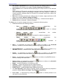
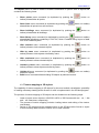
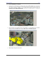
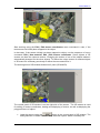
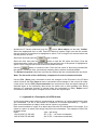
Digital Photogrammetric System Version 6.0 USER MANUAL Three-dimensional modeling PHOTOMOD 6.0 1. Three-dimensional modeling – 3D-Mod ..................................................................................................... 3 1.1. Main menu of 3D-Mod program ............................................................................................................... 3 1.2. Texture mapping to 3D objects ................................................................................................................ 8 1.2.1. Texture mapping to 3D objects ......................................................................................................... 9 1.2.2. Objects editing in 3D Mod ............................................................................................................... 13 1.2.2.1. Removing of the stereo-plotting errors of the initial 2D vector objects ..................................................................... 13 1.2.2.2. Editing of 3D objects ................................................................................................................................................. 16 1.3. Appendix A. Description of ASCII format ............................................................................................... 17 1.4. Appendix B. Description of ASCII-A format ........................................................................................... 18 © 2013 2 Project processing 2014 1. Three-dimensional modeling – 3D-Mod 3D-MOD module is intended for building of 3D-objects using vectors with classifier created in PHOTOMOD system (see the chapter Vector layer with classifier), editing, texture mapping and for subsequent export of resulting file to the necessary data format for further use in other software. There is the following workflow: Export vectors with attributes to ASCII-A format (see the chapter Export to ASCII-A); Start 3D-Mod program; Import of vectors from ASCII-A-file and transforming them to the 3D-Mod native format (*.tx3); 3D modeling (including the editing and texture mapping of 3D objects); Export to the necessary data format. 1.1. Main menu of 3D-Mod program The File menu is used for import of vector objects from ASCII-A-file to 3D-Mod and export of resulting objects of 3D-Mod system to the necessary data format for further use in other software. Menu consists of the following items: Open – opens the file of vector objects in the 3D-Mod native format (*. tx3). Save – allows saving the current file or changes of the current file to the 3D-Mod native format. Save as – allows saving the current file or changes of the current file under a new name in the 3D-Mod native format. Import – allows to import vector objects from ASCII-A-file and to transform them to native format of 3D-Mod. The command opens a window for ASCII-A-file (*.txt) selection. Format ASCII-A allows to store vector objects attributes along with their metrics (see Appendix B). After selection of .txt file, push the Open button to specify parameters in the Parameters of import and building window: 3 RACURS Co., Ul. Yaroslavskaya, 13-A, office 15, 129366, Moscow, Russia PHOTOMOD 6.0 Import parameters The Parameters of import and building window consists of 4 sections, where you can specify settings of coordinate system (which is defined in PHOTOMOD project), setup parameters of objects building, specify reference DXF-file (path to DXF-file that contains a description of point objects geometry) and level: Import section: - Coordsystem – specify Left or Right coordinate system according to parameters of coordinate system defined in PHOTOMOD project; - Build 3D objects – enable this option to build 3D objects; 3D modeling section: - - © 2013 Join vertices tolerance – allows to merge vertices, if the distance between them is less than specified value; Overlapped vertices mode sets the processing rule for vertices with the same XY during the 3D-models building; Use objects without assignment – allows to use lines (Build objects from closed lines) and contours (Include points to 3D modeling) without attributes, just as a bounding contours; Planar geometry – enables algorithm used to eliminate self-crossing of vector objects and bounding contours in XY plane. Process by layers mode allows to process elements (closed contours, lines) during the 3D-model building independently for each layer, to remove unwanted interaction between elements from different layers and accelerate processing; 4 Project processing 2014 Reference DXF-file section: - Link by code – allows to link point objects with geometry containing in DXFfile by code of object (see Appendix B). - Link by codename – allows to link point objects with geometry containing in DXF-file by name of object code (see Appendix B). - Path – allows to specify path to DXF-file that contains a description of point objects geometry. Push the button to specify a path, after that a dialogue for DXF-file selection is opened. Once DXF-file is selected, push the Accept button to perform import. Level section: - Level – set the level of height, on which the side faces of objects will be projected; Grid – specifies path to the DEM, which sets a lower limit during the 3D objects creating. Export – used to export objects of 3D-MOD system to the necessary data format for further use in other software. To perform data export to DXF format (exchange format of AutoCAD system) select menu command File | Export, resulting in opening of the Export window which allows to create output file with selected extension (*.dxf, *.txt, *.tx3, *.dae, *.3ds). Export selected – used to export selected objects of 3D-MOD system to selected format – opens the window for format file selection (Export). Close – closes the current file with the ability of data saving. Exit – closes 3D-Mod program. The Edit menu is used for work with objects imported from PHOTOMOD system. Menu consists of the following items: 5 Select – (is duplicated by pushing the allows to select objects in view area. Select by name – (is duplicated by pushing the button on toolbar or by Ctrl-N shortcut) – allows to select objects in view area using a list. After selecting the command the Select objects window is opened. It contains a list of names shown as a table, the Filter panel and three buttons below the panel, used for managing of objects list. button on toolbar or by Ctrl-S shortcut) – RACURS Co., Ul. Yaroslavskaya, 13-A, office 15, 129366, Moscow, Russia PHOTOMOD 6.0 The list of objects names of 3D-MOD system The list of names contains the following columns: Name – unique name with length not exceeding 64 symbols, which is assigned to each object; Type – object type. May have following values: Geometry, Contour, Line, Point. Assignment – attribute, that defines a way of using of imported objects during creating 3Dobjects (LibPoint, Break, Object). State – Used/Free – status of imported objects during 3D-objects creation – used/not used. The Filter panel is used to select the following filters: Assigned points/Free points – Assigned lines/Free lines – Buildings – 3D-objects created using objects imported from StereoDraw module. Library – 3D-objects created using point objects imported from StereoDraw module and DXF-file that contains a description of objects geometry. There are the following buttons that allow to manage the objects list: - Select all – selects all items in the list; - Inverse – inverts selection (all selected objects become deselected and all deselected objects become selected); - Clear – cancels selection of all items of the list; When you selected all necessary filters, click the Select button. Select dependent menu command (is duplicated by pushing the button on toolbar) allows to select both the whole object and all elements (contours, breaklines), used to create objects in 3D-MOD system. Select unused objects menu command (is duplicated by pushing the button on toolbar) allows to select elements (contours, breaklines), that are not used to create objects in 3D-MOD system. © 2013 6 Project processing 2014 Edit texture coordinates menu command activates the editing mode of the texture coordinates of 3D objects (see chapter Texture mapping to 3D objects). New material menu command allows specifying the unique texture for the selected object. Some objects of 3D scenes can have the common texture. Changing the texture of one of the objects makes it automatically changed for the other objects. To define the unique texture for selected object of 3D scene it’s necessary previously to define the new material for it. Edit menu command activates the editing mode of vertices, edges and faces of 3D object (see chapter Objects editing in 3D Mod). Delete menu command (is duplicated by the Del key) – deletes selected objects. Delete all menu command – deletes all objects. The View menu is used to manage view area. It contains the following items: Tools shows/hides the following toolbars: - View control tools - shows/hides toolbar visualization area and to stereo mode selection. - Objects control tools - the , used to manage shows/hides the toolbar , intended for objects management. - Object hidden tolls - toolbar manage visualization mode of different objects types. , intended the to Move - (is duplicated by pushing the button on toolbar or by Ctrl-Alt-M shortcut) – allows to move view area by mouse using drag-and-drop mode. Approach/Distance - (is duplicated by pushing the button on toolbar or by Ctrl-Alt-F shortcut) – allows to move view area closer or farther from user. Rotate - (is duplicated by pushing the button on toolbar or by Ctrl-Alt-R shortcut) – allows to rotate view area by mouse with pressed left mouse button. Zoom - (is duplicated by pushing the allows to change view area scale. Select region - (is duplicated by pushing the button on toolbar or by Ctrl-Alt-S shortcut) – defines borders of view area. Edges – viewing 3D objects in a wireframe model. Textures – viewing 3D objects with the mapped texture. Anaglyph stereo – enables/disables anaglyph stereomode. Frame stereo – enables/disables page-flipping stereomode. The View direction option allows to specify 6 basic orthogonal and one perspective projection (Front, Back, Left, Right, Top, Bottom, Perspective). 7 shows/hides button on toolbar or by Ctrl-Z shortcut) – Four views – (is duplicated by pushing the view area in four projections. button on toolbar) allows to see RACURS Co., Ul. Yaroslavskaya, 13-A, office 15, 129366, Moscow, Russia PHOTOMOD 6.0 The Objects menu is used to enable or disable visualization of specific sets of objects and contains the following items: Show points menu command (is duplicated by pushing the toolbar) shows/hides all points. Show lines menu command (is duplicated by pushing the shows/hides all points lines and contours. Show buildings menu command (is duplicated by pushing the toolbar) shows/hides all buildings. Show library menu command (is duplicated by pushing the button on toolbar) shows/hides all objects containing in DXF-file, which is added during import of data from PHOTOMOD system. Hide selected menu command (is duplicated by pushing the toolbar) allows to hide selected objects. button on Hide by name menu command (is duplicated by pushing the toolbar) allows to hide objects selected by name. button on Hide unselected menu command (is duplicated by pushing the toolbar) allows to show selected objects. button on Unhide by name menu command (is duplicated by pushing the toolbar) allows to show objects selected by name. button on Unhide all menu command (is duplicated by pushing the button on toolbar) shows all objects. Build menu command allows building 3D objects by selected vectors. button on button on toolbar) button on 1.2. Texture mapping to 3D objects The capability of texture mapping to 3D objects for the most realistic visualization: possibility of making necessary shading and/or illusion of relief is implemented in the 3D Mod program. The process of texture mapping to 3D-objects can be divided into the following steps: - © 2013 Load or import vector objects in ASCII3D, ASCII or 3DS formats with the *. txt, *. 3ds and *. tx3 extensions, respectively; The process of texture mapping includes: loading texture and editing of the texture coordinates; Saving of 3D objects with the mapped texture to the 3D Mod native format or export to the necessary data format for further use in other software. 8 Project processing 2014 1.2.1. Texture mapping to 3D objects Load the file of 3D objects in working area using the File | Open menu command (the dialog selection of datafile in the 3D Mod native format is opened when the command) or the File | Import menu command (the dialog selection of supported formats is opened when the command). General view of 3D scene 9 Set the object in the working area of 3D window in a comfortable view to texture mapping using the Toolbar (see chapter Main menu of 3D Mod program). Select object using the mouse click. RACURS Co., Ul. Yaroslavskaya, 13-A, office 15, 129366, Moscow, Russia PHOTOMOD 6.0 Start working using the Edit | Edit texture coordinates menu command in case, if the texture was not initially been mapped to the object. In that case, if the texture initially has been mapped to object, use the sequence of menu command: Edit | New material, Edit | Edit texture coordinates. Some objects of 3D scenes can have the common texture. Changing the texture of one of the objects makes it automatically changed for the other objects. To define the unique texture for selected object of 3D scene it’s necessary previously to define the new material for it. The working area of 3D window divides into 2 parts (3D and 2D). The control panel of 2D window is on the right side of the screen. The 2D window is used for editing of texture coordinates, loading and displaying of texture, as well as displaying the polygonal frame of object. © 2013 Load the texture using the button in the control panel of 2D window. The dialog selection of raster file with *.bmp extension opens. Select necessary file. 10 Project processing 2014 Start the process of the texture mapping by editing texture coordinates. This process is performed by “binding” raster images to the vertices of faces of the polygonal frame. And it is showed in the 3D window in real time, with corresponding vertices, which are displayed simultaneously (in the form of the origin of coordinates icon), for the most correctly mapping of the texture on the object. Select the part of object (face) in the F (faces) mode using the left mouse key and Shift button and push the button for mapping the selected fragment of texture to corresponding face of 3D object. Push the button (Move object) on the main Toolbar. Point the selected face of polygonal frame with the marker in 2D window. Drag the face by moving the mouse along with its left button pressed and pull toward to the corresponding raster image. Then, it is necessary “to bind” the texture to the vertices of selected face of the polygonal frame. Activate the P (point) mode. Push the button (Move object) on the main Toolbar. Select one of the vertices by clicking and dragging it using the left mouse button, move it to the needed position on a raster image (3D window shows in real time the vertice of a face which a fragment of texture is bound to). 11 RACURS Co., Ul. Yaroslavskaya, 13-A, office 15, 129366, Moscow, Russia PHOTOMOD 6.0 Select the next face of object and continue the process of texture mapping. During the texture coordinates editing the necessity to change position of edited face in the 2D window may occur to texture mapping correctly. Use the button. Set the editable face in the working area of 3D window in a comfortable view and push the button. Editable face displays in the 2D window in the same view. Activate the F (faces) mode and push the button (Move object) on the main Toolbar for the polygonal frame movement in the 2D window. Select the polygonal frame by clicking and dragging it using the left mouse button, point it with the marker, move it to the needed position the same way. The button is performed to change size of polygonal frame or its faces. Activate the P (point) mode. Select the polygonal frame or face by clicking and dragging it using the left mouse button and push the button. The zoom tool displays around the object. Pull one of the frame corners to change size. © 2013 12 Project processing 2014 Use the File | Save menu command to save the changes in the 3D scene in the 3D Mod native format or the File | Save as menu command to save changes in the current file under a new name. Use the File | Export selected menu command to save and export changes of selected object to the necessary data format for further use in other software (the dialog selection of supported formats is opened when the command). 1.2.2. Objects editing in 3D Mod The editing feature in the 3D Mod program is implemented for removing stereo-plotting errors of the initial 2D vector objects and editing of already created 3D objects. 1.2.2.1. Removing of the stereo-plotting errors of the initial 2D vector objects Import the layer of initial 2D vector objects for editing using the File | Import menu command. Select the editable object by mouse clicking. 13 RACURS Co., Ul. Yaroslavskaya, 13-A, office 15, 129366, Moscow, Russia PHOTOMOD 6.0 Use the Edit | Edit menu command. Activate the P (point) mode and push the removing of stereo-plotting errors. © 2013 button (Move object) on the main Toolbar for 14 Project processing 2014 Point the reference system origin icon with the marker the way that one of the planes is highlighted in yellow. Pull it using the left mouse button and edit the object. Use the Objects | Build menu command for creating 3D object from edited vectors. Use the File | Save menu command to save the changes in the 3D scene in the 3D Mod native format or the File | Save as menu command to save changes in the current file under a new name. Use the File | Export selected menu command to save and export changes of selected object to the necessary data format for further use in other software (the dialog selection of supported formats is opened when the command) or the File | Export menu command to save and export changes from the whole 2D objects layer. 15 RACURS Co., Ul. Yaroslavskaya, 13-A, office 15, 129366, Moscow, Russia PHOTOMOD 6.0 1.2.2.2. Editing of 3D objects Open the necessary 3D object or scene for editing using the File | Open menu command. Select the editable object by mouse clicking. Use the Edit | Edit menu command. For 3D objects vertices editing: Activate the P (point) mode and push the button (Move object) on the main Toolbar. Select the appropriate vertex to edit. Point the reference system origin icon with the marker the way that one of the planes is highlighted in yellow. Pull it using the left mouse button and edit the position of vertex. Select the vertex and push the button to delete. Select the vertices and push the Use the button to join topologycally the several vertices. button to divide vertices. For 3D objects faces editing: © 2013 16 Project processing 2014 Activate the F (faces) mode and push the button (Move object) on the main Toolbar. Select the appropriate face to edit. Point the reference system origin icon with the marker the way that one of the planes is highlighted in yellow. Pull it using the left mouse button and edit the position of face. Select the face and push the button to delete. Select the face and push the button to split the 3D object into faces. Point the reference system origin icon with the marker the way that one of the planes is highlighted in yellow. Pull it using the left mouse button and detach the face. Use the button to create the face. Point the first vertex of face being created with the marker. Create the face, successively selecting three vertices counterclockwise. The Delete free points check box removes the vertices that are not attached with any faces. Note: The front side of face defined by a sequence of vertices counterclockwise. Use the File | Save menu command to save the changes in the 3D scene in the 3D Mod native format or the File | Save as menu command to save changes in the current file under a new name. Use the File | Export selected menu command to save and export changes of selected object to the necessary data format for further use in other software (the dialog selection of supported formats is opened when the command) or File | Export menu command to save and export changes from the whole 2D objects layer. 1.3. Appendix A. Description of ASCII format In this format each vector object is represented as a sequence of vertices described by their 3D coordinates. The file of this format is a sequence of records separated by “*” symbol. Each record describes an object, which can be a point or a polylines. Each record consists of a type of an object and rows with 3D coordinates of its vertices. If an object is a point, its name (text string) may follow its coordinates. The example of ASCII file is shown below. Road - type - text string; 1234.67,4567.67,565.453 - X1,Y1,Z1 - 1-st vertex coordinates; 1245.6,7439.570,860.958 - X2,Y2,Z2 - 2-nd vertex coordinates; ... - ... 17 RACURS Co., Ul. Yaroslavskaya, 13-A, office 15, 129366, Moscow, Russia PHOTOMOD 6.0 * Point 1257.85,2198.76,459.56,Point1 text); * ... - separator of object descriptions; - type - text string; - X, Y, Z - point coordinates and name (arbitrary - ... - ... 1.4. Appendix B. Description of ASCII-A format In addition to vertices coordinates the extended ASCII-A format contains the following information: an object type, a layer number, names and values of an object attributes. The structure of this format file is mainly the same as of ASCII format file. But the header of the file contains several lines, describing an object type and attributes. Below is an example of an object description section with explanation: L 101 1 15 6 OBJECT_NAME=Highway OBJECT_COLOR=3 OBJECT_SYMBOL=R OBJECT_SIZE=5.5 WIDTH=7.2 ROADNAME= Highway_1234 545566.505,473671.817,77.850 545715.103,473656.072,78.310 545782.001,473567.393,78.156 545860.428,473463.139,77.974 545847.506,473339.305,77.380 545795.032,473249.288,76.795 545517.126,473365.500,76.318 545269.605,473463.426,75.869 * The first line of an object description has the following structure: Type Code Layer N1 N2, where: Type - the symbol describing an object type (L, P, C, R); Code - the code of an object; Layer - the layer number; N1 - the total number of lines of an object description; N2 - the number of lines describing object attributes. Then lines with descriptions of attributes follow. An attribute description line looks like: Name=Value There are four following attributes with reserved names: OBJECT_NAME – name of object; OBJECT_COLOR – number of object color; OBJECT_SYMBOL – symbol assigned to object; OBJECT_SIZE – size of object. During import values of these attributes are assigned to the Name, Color, Symbol and Size properties respectively. Lines with an object attributes description are followed by the lines with coordinates of object vertices. The coordinate description lines have the same format as described above for the ASCII format without attributes. Groups of lines corresponding to objects descriptions are separated by lines with the “*” symbol, but unlike the previous case, these lines are not obligatory because the beginning of an object description is recognized by its first line. © 2013 18 Project processing 2014 The main role in recognizing of the beginning of objects description plays the first string. In addition to standard some attributes are used during 3D-objects creation. These objects have the following default names and appropriate function: object= - contour or line with this attribute is bounding contour; - contour, line or point with this attribute is break line; - point with this attribute specifies a height of library object; - contour, line or point with this attribute is not used for objects creation. break= library= none= 19 RACURS Co., Ul. Yaroslavskaya, 13-A, office 15, 129366, Moscow, Russia