1
Freescale Semiconductor, Inc.
M68PCBUG11/D
REV 3
Freescale Semiconductor, Inc...
December 1996
M68HC11 PCbug11
USER'S MANUAL
© 1991, 1992, by MOTOROLA, INC.
For More Information On This Product,
Go to: www.freescale.com
Freescale Semiconductor, Inc...
Freescale Semiconductor, Inc.
Motorola reserves the right to make changes without further notice to any products herein to
improve reliability, function, or design. Motorola does not assume any liability arising out of the
application or use of any product or circuit described herein; neither does it convey any license
under its patent rights nor the rights of others. Motorola products are not designed, intended, or
authorized for use as components in systems intended for surgical implant into the body, or other
applications intended to support or sustain life, or for any other application in which the failure of
the Motorola product could create a situation where personal injury or death could occur. Should
Buyer purchase or use Motorola products for any such unintended or unauthorized application,
Buyer shall indemnify and hold Motorola and its officers, employees, subsidiaries, affiliates, and
distributors harmless against all claims, costs, damages, and expenses, and reasonable attorney
fees arising out of, directly or indirectly, any claim of personal injury or death associated with
such unintended or unauthorized use, even if such claim alleges that Motorola was negligent
regarding the design or manufacture of the part. Motorola is a registered trademark of Motorola,
Inc. Motorola, Inc. is an Equal Opportunity/Affirmative Action Employer.
IBM is a trademark of International Business Machines Corp.
MS-DOS is a trademark of Microsoft Corporation.
For More Information On This Product,
Go to: www.freescale.com
Freescale Semiconductor, Inc.
CONTENTS
CONTENTS
Freescale Semiconductor, Inc...
CHAPTER 1
GENERAL INFORMATION
1.1 INTRODUCTION............................................................................................................. 1-1
1.2 MCU SETUP FOR PCBUG11 .......................................................................................... 1-1
1.2.1 Hard Disk Installation ............................................................................................... 1-2
1.2.2 Flexible Disk Installation ........................................................................................... 1-2
1.3 STARTING PCBUG11 ..................................................................................................... 1-3
1.3.1 Running the Software................................................................................................ 1-3
1.3.2 Monitor Screen Windows.......................................................................................... 1-4
1.3.3 Fixing Simple Problems............................................................................................. 1-5
1.3.4 Trying Simple Commands ......................................................................................... 1-6
1.4 HOW PCBUG11 WORKS ................................................................................................ 1-7
CHAPTER 2
USING PCBUG11 SOFTWARE
2.1 INTRODUCTION............................................................................................................. 2-1
2.2 PCBUG11 RUNTIME COMMAND STRUCTURE.......................................................... 2-1
2.2.1 The <baudrate> Parameter ........................................................................................ 2-1
2.2.2 Runtime Command Examples.................................................................................... 2-3
2.3 USES OF THE SOFTWARE ............................................................................................ 2-3
2.4 PITFALLS TO AVOID..................................................................................................... 2-4
M68PCBUG11/D
For More Information On This Product,
Go to: www.freescale.com
iii
Freescale Semiconductor, Inc.
CONTENTS
Freescale Semiconductor, Inc...
CHAPTER 3
USING PCBUG11 COMMANDS
3.1 INTRODUCTION............................................................................................................. 3-1
3.2 COMMAND-LINE EDITING........................................................................................... 3-1
3.3 PCBUG11 COMMANDS.................................................................................................. 3-2
ASM addr [mne|dir]........................................................................................................... 3-5
BAUD [rate]...................................................................................................................... 3-7
BF addr1 [addr2] byte|word............................................................................................... 3-8
BL..................................................................................................................................... 3-9
BR [addr [macroname]] ................................................................................................... 3-10
CALL addr ...................................................................................................................... 3-11
CLRM ............................................................................................................................. 3-12
CLS................................................................................................................................. 3-13
CONTROL [parameter]................................................................................................... 3-14
DASM addr1 [addr2]....................................................................................................... 3-15
DB startaddr [endaddr] .................................................................................................... 3-16
DEBUG........................................................................................................................... 3-17
DEFINE symbol value|address......................................................................................... 3-18
DEFM macrnam|TRACE|AUTOSTART ......................................................................... 3-19
DELM macrnam|TRACE|AUTOSTART ......................................................................... 3-21
DIR [mask]...................................................................................................................... 3-22
DOS [command].............................................................................................................. 3-23
EDITM macrnam............................................................................................................. 3-24
EEPROM [startaddr [endaddr]] ....................................................................................... 3-25
EEPROM DELAY option ............................................................................................... 3-26
EEPROM ERASE [option] [addr] ................................................................................... 3-27
EPROM [startaddr [endaddr]] ......................................................................................... 3-28
EPROM DELAY option.................................................................................................. 3-29
FIND byte|word addr1 addr2 ........................................................................................... 3-30
FIND mnemonic addr1 addr2........................................................................................... 3-31
G [addr]........................................................................................................................... 3-32
HELP [command]............................................................................................................ 3-33
KLE ................................................................................................................................ 3-34
LOADM [filename [macroname]] .................................................................................... 3-35
LOADS filename [loadaddr] ............................................................................................ 3-36
LS symbol ....................................................................................................................... 3-37
LSTM [mname|TRACE|AUTOSTART] .......................................................................... 3-38
MD startaddr [endaddr] ................................................................................................... 3-39
MM addr ......................................................................................................................... 3-40
MOVE addr1 addr2 addr3 ............................................................................................... 3-41
MS addr byte|word [byte|word] ....................................................................................... 3-42
iv
For More Information On This Product,
Go to: www.freescale.com
M68PCBUG11/D
Freescale Semiconductor, Inc.
CONTENTS
Freescale Semiconductor, Inc...
CHAPTER 3
USING PCBUG11 COMMANDS (continued)
MSG [string] ................................................................................................................... 3-43
NOBR [address] .............................................................................................................. 3-44
PAUSE [mS] ................................................................................................................... 3-45
PRINT............................................................................................................................. 3-46
PROTECT [startaddr [endaddr]] ..................................................................................... 3-47
QUIT [Y] ........................................................................................................................ 3-48
RD [T] ............................................................................................................................ 3-49
RESET [addr] ................................................................................................................. 3-50
RESTART [option] ......................................................................................................... 3-52
RM.................................................................................................................................. 3-53
RS register value.............................................................................................................. 3-54
S...................................................................................................................................... 3-55
SAVEM [filename] .......................................................................................................... 3-56
SHELL [command] ......................................................................................................... 3-57
T [addr] ........................................................................................................................... 3-58
TERM [X1 Y1 X2 Y2].................................................................................................... 3-59
TYPE filename ................................................................................................................ 3-60
UNDEF symbol ............................................................................................................... 3-61
VER ................................................................................................................................ 3-62
VERF filename [memaddr] .............................................................................................. 3-63
VERF ERASE addr1 [addr2]........................................................................................... 3-64
VERF SET addr1 addr2 value ......................................................................................... 3-65
WAIT [mS] ..................................................................................................................... 3-66
CHAPTER 4
ADVANCED TOPICS
4.1 INTRODUCTION............................................................................................................. 4-1
4.2 MACROS.......................................................................................................................... 4-1
4.2.1 Defining Macros ....................................................................................................... 4-2
4.2.1.1 Autostart Macros ............................................................................................. 4-3
4.2.1.2 Null Macros ..................................................................................................... 4-3
4.2.2 Editing Macros ......................................................................................................... 4-3
4.2.3 Listing and Clearing Macros...................................................................................... 4-4
4.3 USING TRACE AND BREAKPOINTS............................................................................ 4-4
4.3.1 Breakpoints............................................................................................................... 4-4
4.3.2 Tracing ..................................................................................................................... 4-6
4.4 TALKERS IN EEPROM OR EXTERNAL MEMORY ..................................................... 4-6
4.5 PROGRAMMING EPROM (711) PARTS ........................................................................ 4-8
4.6 DESIGNING NEW TALKERS......................................................................................... 4-9
M68PCBUG11/D
For More Information On This Product,
Go to: www.freescale.com
v
Freescale Semiconductor, Inc.
CONTENTS
APPENDIX A
HARDWARE SUPPORT
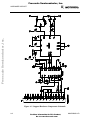
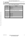
A.1 INTRODUCTION............................................................................................................A-1
A.2 CIRCUIT DIAGRAM AND COMPONENTS LIST ........................................................A-1
Freescale Semiconductor, Inc...
APPENDIX B
PCBUG11 ERROR MESSAGES
B.1 INTRODUCTION ............................................................................................................B-1
B.2 FAILED OPERATION ERRORS.....................................................................................B-1
B.3 COMMUNICATIONS ERRORS AND OTHER FATAL ERRORS ................................B-4
B.4 COMMAND ERRORS.....................................................................................................B-6
B.5 VERIFICATION ERRORS ..............................................................................................B-6
APPENDIX C
vi
PCBUG11 DISK CONTENTS
For More Information On This Product,
Go to: www.freescale.com
M68PCBUG11/D
Freescale Semiconductor, Inc.
GENERAL INFORMATION
CHAPTER 1
GENERAL INFORMATION
Freescale Semiconductor, Inc...
1.1 INTRODUCTION
M68HC11 PCbug11 is a software package for easy access to and simple experimentation with
M68HC11 microcontroller unit (MCU) devices. PCbug11 lets you program any member of the
M68HC11 MCU family and examine the behavior of internal peripherals under specific
conditions. In addition, you may run your own programs on the MCU; breakpoint processing and
trace processing are available.
This manual explains how to install and run PCbug11, version 3.24, as well as how to correct
common problems. (A user who has a later version of PCbug11 should check for any version
information notes attached to the end of this manual. Such notes contain information about any
changes from the information of the main text.)
Terminology conventions for this manual are:
•
The acronym MCU denotes any member of the family of M68HC11 microcontroller
unit devices.
•
Two-character, alphabetic and numerical codes denote specific MCUs. For example,
A8, D3, and E9 denote the MC68HC11A8, the MC68HC11D3, and the
MC68HC11E9, respectively.
•
Monitor, or monitor program, is another term for PCbug11.
1.2 MCU SETUP FOR PCBUG11
Before you use an M68HC11 MCU with PCbug11, you must prepare hardware support
components and install the software on an IBM PC or compatible personal computer. For
information on hardware components, consult Appendix A.
Motorola supplies the software on a 360-Kbyte, IBM PC compatible master disk. You must
install this software on the hard disk of your computer, per paragraph 1.2.1.
Optionally, if your computer does not have a hard disk, you may run PCbug11 from
a flexible disk, per paragraph 1.2.2.
M68PCBUG11/D
For More Information On This Product,
Go to: www.freescale.com
1-1
Freescale Semiconductor, Inc.
GENERAL INFORMATION
1.2.1
Hard Disk Installation
In these instructions, drive A is the flexible disk drive and drive C is the hard disk. Follow these
steps to install the software on a hard disk:
1. Insert the master disk in drive A.
2. Make drive C the default drive (if it is not so already) by typing
C: [RETURN]
Freescale Semiconductor, Inc...
3. Create a new subdirectory by typing
md \PCBUG11 [RETURN]
4. Make this new subdirectory the default byt typing
cd \PCBUG11 [RETURN]
5. Copy all the files from the master disk to the hard disk by typing
copy a:*.* c: [RETURN]
This completes software installation. You may run PCbug11 from anywhere in the hard-disk
directory structure by using the DOS PATH command to include the C:\PCBUG11 subdirectory
in your path. (See DOS documentation for details on the PATH command.)
1.2.2
Flexible Disk Installation
These instructions are for a computer that has two flexible disk drives. Drive A is a 360-Kbyte
flexible disk drive. Drive B is the second flexible disk drive. You need a freshly formatted disk,
which will become your work disk.
Follow these steps to install the software:
1. Insert the master disk in drive A.
2. Insert the formatted disk in drive B. This disk becomes your work disk.
3. Copy all the files from the master disk to the work disk by typing
copy a:*.* b: [RETURN]
4. Remove the master disk from drive A.
5. Remove the work disk from drive B and insert it in drive A.
This completes software installation. You may run PCbug11 from the work disk in drive A.
1-2
For More Information On This Product,
Go to: www.freescale.com
M68PCBUG11/D
Freescale Semiconductor, Inc.
GENERAL INFORMATION
1.3 STARTING PCBUG11
To start the software package, set up the hardware, connect the hardware to the
computer communication port, and run the PCbug11 monitor program.
Freescale Semiconductor, Inc...
1.3.1
Running the Software
PCbug11 is sophisticated software that takes many possible options. The computer port used, the
crystal used, and any macros used determine which options are possible for a specific MCU.
To run the software, enter the startup command. The simplest run command is for an
MC68HC11A8, MC68HC11A1, or MC68HC11A0 MCU, with the XIRQ and PD0 pins
connected:
PCBUG11 -XA
To run other MCUs of the M68HC11 family, alter the final one or two characters of this run
command, per Table 1-1. (As most M68HC11 MCUs have E9 type bootloaders, the -XE option
is the more frequently appropriate.) An X in the run command means that the XIRQ and PD0
pins must be connected (do not use the X option if PCbug11 is used with an EVBU board).
NOTE
The default number base of PCbug11 is 10. To change the default
base to 16, enter the command CONTROL BASE HEX. To
change the default base to 2, enter the command CONTROL
BASE BIN. To change the default base back to 10, enter the
command CONTROL BASE DEC. The CONTROL command
explanation, in Chapter 3, gives more information.
M68PCBUG11/D
For More Information On This Product,
Go to: www.freescale.com
1-3
Freescale Semiconductor, Inc.
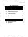
GENERAL INFORMATION
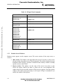
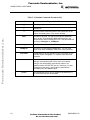
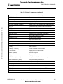
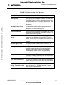
Table 1-1. PCbug11 Run Commands
Freescale Semiconductor, Inc...
MCU
1.3.2
RUN Command
MC68HC11A0,
MC68HC11A1, or
MC68HC11A8
PCBUG11 -A
or
PCBUG11 -XA
MC68HC811A8
PCBUG11 -88
MC68HC11D3 or
MC68HC711D3
PCBUG11 -D
MC68HC11E0,
MC68HC11E1,
MC68HC11E9,
MC68HC11E20,
MC68HC11F1,
MC68HC11G5,
MC68HC11G7,
MC68HC11L6, or
MC68HC811A2
PCBUG11 -E
or
PCBUG11 -XE
MC68HC11E2
PCBUG11 -XA
MC68HC711E9
PCBUG11 -E
MC68HC11K4,
MC68HC711K4,
MC68HC11N4, or
MC68HC11P2
PCBUG11 -K
Monitor Screen Windows
Hardware status appears on the computer screen. This screen consists of four major areas, or
windows:
1. Main window. This window is the upper half of the screen. If you have a color screen,
the main window has white text on a blue background. This window displays the most
information about PCbug11 operation: command results, memory contents, assembly
opcodes, macros, and so forth.
2. Register window. This window is in the center of the screen. If you have a color
screen, the register window has white or yellow text on a red background. This
window shows the last recorded contents of the processor registers. Note that register
window values update only upon startup or user request. PCbug11 commands let you
modify the contents of the registers.
1-4
For More Information On This Product,
Go to: www.freescale.com
M68PCBUG11/D
Freescale Semiconductor, Inc.
GENERAL INFORMATION
3. Status window. This window is at the center right of the screen. If you have a color
screen, the status window has white text on a purple background. This window shows
the MCU in use; the MCU state (running, stopped, tracing); the status of the RS232
RTS line, and the current user-set interrupt vectors.
Freescale Semiconductor, Inc...
4. Command window. This window is at the bottom left of the screen. If you have a
color screen, the command window has white text on a black background. Use this
window for entering and reading commands to PCbug11. The command cursor (the »
character) is at the bottom line of this window; commands you enter appear after the
command cursor. Previous commands and the latest error message also appear in the
command window.
If your screen does not show these windows, the program is not running correctly. A DOS error
message or a PCbug11 error message indicates the problem. See paragraph 1.3.3 or Appendix B
for guidance on corrective action. If your screen does show these four windows, proceed to
paragraph 1.3.4 to try some simple commands.
There are two additional, temporary windows, which appear superimposed over the
main window:
1. Error window. This window indicates any errors or incorrectly operating
communications to the MCU. If you have a color screen, the error window has red
text on a black background. To clear the error window immediately, press any key.
(Or wait five seconds and the error window clears itself.)
2. Help window. This window displays help information requested via the HELP
command. If you have a color screen, the help window has white text on a black
background. To scroll through the help information, use the up-arrow, down-arrow,
page-up, and page-down keys. To clear the help window, press the ESC key.
1.3.3
Fixing Simple Problems
If the software did not start up correctly, the register screen shows rows of characters X instead
of values, and one or more error messages appear in the command window. Appendix B explains
the full meaning of such an error message.
M68PCBUG11/D
For More Information On This Product,
Go to: www.freescale.com
1-5
Freescale Semiconductor, Inc.
GENERAL INFORMATION
Freescale Semiconductor, Inc...
In the case of an initial startup, however, the most likely problems are a poor communications link
or an incorrect hardware setting. Make sure that:
•
A 5-volt signal is supplied correctly to the user hardware.
•
An 8 MHz crystal is installed in the circuit.
•
The communications cable is wired correctly.
•
The MCU is in bootstrap mode and is reset.
•
The cable is connected to the COM1 port of the computer (or the guidance of
paragraph 2.2 is followed if the cable is connected to the COM2 port).
After checking these items, try again to start the system. If numerical values appear in the register
window and there are no error messages, PCbug11 is working correctly. Proceed to the simple
commands of paragraph 1.3.4.
1.3.4
Trying Simple Commands
This paragraph explains a few simple commands that demonstrate PCbug11 operation. (Paragraph
3.2 explains the full PCbug11 command set.)
<CTRL>R
This command tests communications between the user hardware and the
computer. If communications are operating correctly, the response
Communications synchronized
appears in the main window. Otherwise, the response
Communications fault
appears in the main window.
1-6
RESTART
This command reloads the communications program and starts afresh, so it
is appropriate any time there is an indication of a communications fault. Be
sure to reset the MCU before typing in RESTART. Note, however, that
this command may lead to the loss of any program in processor RAM.
QUIT
This command terminates a PCbug11 session. After you type in QUIT, a
message requests confirmation that you really do want to end the session.
Respond affirmatively, and the session ends.
RD
This command displays register contents, letting you read the values.
Should rows of the character X appear instead of values, an error message
identifies the problem.
For More Information On This Product,
Go to: www.freescale.com
M68PCBUG11/D
Freescale Semiconductor, Inc.
GENERAL INFORMATION
MD start_address (end_address) This command displays contents of
memory, from the start address through the end address. If you do not
enter the optional end address, PCbug11 displays the contents of the 16
memory locations beginning with the start address. Memory contents
appear in the main window. (If the address values consist only of digits, the
monitor considers them decimal numbers. To specify binary or hexadecimal
addresses, start them with the % or $ character, respectively.)
CLS
Freescale Semiconductor, Inc...
HELP (command)
This command clears the main window.
This command is valid only if you have installed the help file. Enter HELP
command by itself to see a summary of PCbug11 commands. Enter HELP
followed by another command to see specific help information on the other
command.
1.4 HOW PCBUG11 WORKS
PCbug11 works differently from most other microcomputer emulators or trainers. Other
emulators run sophisticated programs that communicate with a terminal. Such a program lets the
user execute programs, alter registers, and so forth, but requires a complex hardware platform.
The PCbug11 design, however, takes advantage of the sophistication of the PC. The
microcomputer need run only a simple program, so the hardware platform also can be simple.
PCbug11 carries out emulator functions via serial communication with the PC.
The monitor communicates with the MCU through a low-level program called a talker. PCbug11
includes different talkers to support different MCUs and different operating modes. All talkers
communicate between the SCI port of the MCU and the serial port of the PC. Each talker
occupies less than 256 bytes of MCU memory space and operates under interrupt. Some talkers
use internal MCU RAM: this approach is the boot method. Other talkers use internal EPROM or
other ROM: this approach is the ROMed method.
In the boot method, the PC downloads the talker into MCU internal RAM for each PCbug11
startup. Such a download happens via the special bootstrap mode of the MCU. In this mode, the
MCU automatically can download a program into its internal RAM and then run the program.
This makes it possible to alter internal values, program memory, read and write to chip ports, and
perform other functions. This simple approach requires no external hardware except a power
supply, an oscillator, and an RS-232C interface. The limitation of the boot method is its use of
about 240 bytes of internal RAM, which may be a problem for some users.
In the ROMed method, the PC synchronizes communication with a talker already running on the
MCU. This means that the appropriate talker must be programmed into internal or external MCU
memory before the user runs PCbug11. The simplest example of using the ROMed method is
placing the talker in external memory and running the talker every time the MCU is powered up.
If the talker is loaded into the MCU's internal EEPROM, no external memory is required.
M68PCBUG11/D
For More Information On This Product,
Go to: www.freescale.com
1-7
Freescale Semiconductor, Inc.
GENERAL INFORMATION
As a talker is interrupt driven, residing in the same memory map as user software, the RESET,
XIRQ, and SWI vectors must be reserved for talker code. Note, however, that the SCI vector
may be used instead of the XIRQ vector, to give maskable control to PCbug11.
The PCbug11 design leads to these rules of thumb:
1. If the PCbug11 is in boot mode, MCU internal RAM contains the talker program,
bootstrap-mode interrupt vectors, and the program stack. For an MCU that has 256
bytes of RAM, this leaves little room for user programs. In such a case, the user
should use EEPROM space for programs.
Freescale Semiconductor, Inc...
2. PCbug11 is interrupt driven, so the user must consider carefully any program that uses
interrupts or changes interrupt vectors. In the standard approach, the XIRQ pin causes
an interrupt whenever the user needs communications. This gives the user reasonably
free use of interrupts that set the I bit. But the user must be careful when using
breakpoint or trace operations, which also set the I bit. The user also must protect the
interrupt vectors from alteration; changes to these vectors cause loss of
communication with the program.
3. PCbug11 implements trace and breakpoint operations by placing a software interrupt
at the trace or breakpoint location. This means that PCbug11 must be able to modify
the code at such locations: the code must be in (internal or external) RAM or
EEPROM. The monitor cannot operate trace or breakpoints in ROM. This restriction
also applies to FLASH memory, which is not byte programmable. Note that PCbug11
makes use of a little software overhead to handle correctly any user-defined SWI.
(Breakpoints and tracing are not available with D3 or D0 MCUs.)
1-8
For More Information On This Product,
Go to: www.freescale.com
M68PCBUG11/D
Freescale Semiconductor, Inc.
USING PCBUG11 SOFTWARE
CHAPTER 2
USING PCBUG11 SOFTWARE
Freescale Semiconductor, Inc...
2.1 INTRODUCTION
This chapter introduces the user to several possibilities for using PCbug11 software. This
discussion also covers the runtime command structure and common pitfalls to avoid.
2.2 PCBUG11 RUNTIME COMMAND STRUCTURE
To use PCbug11, enter the runtime command at the DOS prompt. The syntax for this command
is:
PCBUG11 [[?]|[[-[X][talker]|[talker]][macro=macroname(params)][baud=baudrate] [port=1|2]]
Table 2-1 is the key to runtime command symbols and parameters.
2.2.1
The <baudrate> Parameter
If your circuit uses an 8 MHz crystal, the standard for PCbug11, do not use the <baudrate>
parameter in the runtime command. In this case, the PC communications rate is 9600 baud, and
the download rate for a -<name> talker is 7812 baud.
For a circuit that uses an alternative crystal, the <baudrate> parameter is required:
•
For a <boottype> talker, the <baudrate> value is the download rate for the talker. This
value must be to 7812 as the frequency (in MHz) of your crystal is to 8. That is,
<baudrate> =
•
crystal used MHz
* 7812
8
For a <ROMtype> talker, the <baudrate> value is the communications rate for the PC
and MCU. This value must be to 9600 as the frequency (in MHz) of your crystal is to
8. That is,
<baudrate> =
M68PCBUG11/D
crystal used MHz
* 9600
8
For More Information On This Product,
Go to: www.freescale.com
2-1
Freescale Semiconductor, Inc.
USING PCBUG11 SOFTWARE
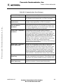
Table 2-1. Runtime Command Parameter Key
Symbol or Parameter
[]
Freescale Semiconductor, Inc...
Enclose optional parameters.
|
Indicates or.
?
The query option. Enter this option to see a short form of the
runtime command syntax, if you need a reminder.
talker
The talker to be used. If a hyphen precedes this parameter
value, the file TALK<boottype>.BOO/.XOO must be in the
same directory as the file PCBUG11.EXE. This parameter has
two forms, <boottype> or <ROMtype>.
<boottype>
A, D, E, K, 88, or <userdefined>
<ROMtype>
The name of a user-defined ROMed talker. The user must
supply a file called <ROMtype>.MAP in the current directory.
<baudrate>
The baudrate for the PC and MCU if your circuit does not use
an 8 MHz crystal. Paragraph 2.2.1 explains more about this
parameter.
<macroname>
The name of a macro library file, such as <macroname>.MCR.
PCbug11 automatically loads such a macro upon startup.
PCbug11 also automatically executes this macro if the
additional macro AUTOSTART also is in the library. To pass
parameters to this macro, enclose them in parentheses
immediately after the macro= option.
port=2
2-2
Explanation or Role
The command to use PC port 2, instead of the default port 1,
for communications with the hardware.
For More Information On This Product,
Go to: www.freescale.com
M68PCBUG11/D
Freescale Semiconductor, Inc.
USING PCBUG11 SOFTWARE
2.2.2
Runtime Command Examples
Freescale Semiconductor, Inc...
Some examples of the PCbug11 runtime command are:
PCBUG11
Entering the runtime command without any options invokes the command
line compiler. This lets the user input option information by answering a
series of prompts instead of making option information part of the runtime
command. This form of the runtime command may be appropriate if you
convert from one MCU to another or if you try a new option.
PCBUG11 ?
Entering the runtime command with the query option tells the monitor to
display a short form of the runtime command syntax.
PCBUG11 -E
This form of the runtime command runs the boot option talker for an MCU
of the M68HC11E, F, G, or L series. The monitor program downloads the
talker to RAM, then runs the talker.
PCBUG11 -XA port=2
This form of the runtime command runs the boot option talker for
an M68HC11A8, A1, A0, or E2 MCU, using PC port 2 (if port 2 exists).
The monitor program downloads the talker to RAM, then runs the talker.
PCBUG11 -XE macro=TRYIT
This form of the runtime command runs the boot option
talker for an MCU of the M68HC11E, F, G, or L series and also loads the
macro TRYIT.MCR. If the AUTOSTART macro is in the macro library,
TRYIT execution begins automatically. (Paragraph 4.2 gives more
information about macros.)
PCBUG11 TALKEREE baud=4800 macro=LISTIT (1 2 3)
For this form of the runtime
command, the talker TALKEREE already must be loaded in the MCU. The
value 4800 is the PC-to-MCU communications rate that corresponds to a 4
MHz crystal. This command also loads the macro LISTIT.MCR and passes
the parameters 1 2 3. (Note that for correct operation of this talker,
PCbug11 must be able to load the file TALKEREE.MAP, which contains
necessary system variables. TALKEREE.MAP must be in the user's current
working directory. Paragraph 4.4 explains more details.)
2.3 USES OF THE SOFTWARE
Possible uses for the PCbug11 software are unlimited. Note that the PCbug11 is not a software
simulation of an MCU; commands and programs you enter run on the real hardware, although via
a software interface. Most of the time the hardware runs the MCU in special bootstrap mode, so
access to secured resources is at user discretion, not under MCU control.
As the package runs under interrupt, it is possible to have a program running, but still be able to
read registers, write to registers, and even write to memory. A careful user can even modify the
M68PCBUG11/D
For More Information On This Product,
Go to: www.freescale.com
2-3
Freescale Semiconductor, Inc.
USING PCBUG11 SOFTWARE
program being run. Note that during modification of a program or registers, the running program
waits for processing of the interrupt caused by PCbug11.
Freescale Semiconductor, Inc...
You may set breakpoints in the software, so the MCU stops whenever it reaches that point in the
code. The trace command lets you step through code to examine the execution of instructions,
and see the results in registers and in the condition code register (CCR).
PCbug11 lets the user modify and assemble code into EEPROM as if it were RAM. Although the
MCU has an elaborate routine for programming this memory, PCbug11 handles such
programming in a manner transparent to the user. To make this possible, the user must first use
the EEPROM command to define the area of internal EEPROM. Do not, however, specify
external EEPROM in this way, as the talker automatically handles slow external memories. There
is a significant difference in response times between writing to EEPROM and writing to RAM.
2.4 PITFALLS TO AVOID
Some MCUs have a register that increases EEPROM protection. This is the BPROT register,
which usually is at address $1035. Before either the EEPROM or the CONFIG register can be
programmed, the BPROT register must be modified. Note that PCbug11 does not modify the
BPROT register.
If you program the CONFIG register, remember that the contents of this register usually are not
readable until after MCU reset. Note that if the MCU is reset in bootstrap mode, certain
automatic functions place the part in an appropriate operating mode. If the MCU has a security
mode, clearing the NOSEC bit protects the internal RAM, internal EEPROM, and the internal
CONFIG register. This means that if the part is reset in bootstrap mode, the value of the NOSEC
bit will be 1.
Follow these guidelines to use interrupts with the hardware. Real-time and other such interrupts
are permitted when the I bit (RTII for the real-time interrupt) is clear and the appropriate
interrupt mask is set. An interrupt sets the interrupt I flag. A CLI or RTI instruction clears this
flag; note however, that the flag for an interrupt source remains set. For a real-time interrupt, this
is RTIF; an exit from a real-time interrupt service routine that leaves RTIF set causes another
interrupt immediately. This means that communications with PCbug11 could stop making sense or
that communications could cease (due to stack overflow).
When real-time measurements or calculations are in progress, remember that reading registers or
memory causes interrupts that interfere with logical program operation. This could upset results,
generating wrong answers. Such wrong answers are particularly likely when the processor is
waiting for the logical value on a port pin to change before carrying out some action. If the
change occurs while PCbug checks the processor status, the change could be lost or upset.
Remember that the MCU does its own self-examination; this self-examination does not affect
programs that perform off-line calculations or other functions.
2-4
For More Information On This Product,
Go to: www.freescale.com
M68PCBUG11/D
Freescale Semiconductor, Inc.
USING PCBUG11 SOFTWARE
Freescale Semiconductor, Inc...
PCbug11 implements breakpoints and traces via software interrupts (SWIs). When program
execution arrives at a breakpoint, an interrupt is generated; the internal talker handles this
interrupt. If the user directly uses the SWI, the SWI vector is called. If the SWI is a true
breakpoint, the PC so informs the user. While this common emulator arrangement is effective, it is
limited to use with RAM or EEPROM; ROM does not accomodate breakpoints or traces. There
is another problem if you reset or restart the MCU while all breakpoints are still set: the SWIs
remain in memory (especially EEPROM), displacing other opcodes. To prevent such a situation,
either clear all breakpoints before resetting or restarting the MCU, or reload your code
immediately after a reset or restart.
In bootstrap mode, PCbug11 puts its talker in MCU internal RAM. Overwriting any of the talker
software could cause loss of operations or communications with the MCU. Accordingly, you
should not place any user code or data in the same area as the talker.
This rule applies as well to the interrupt vector area of RAM. Interrupt vectors are redirected
from bootstrap ROM; they indicate that communications are required. If the stack is not initialized
to a suitable value, the interrupt vectors could be altered accidentally. For example, if you
initialized the stack to $FF, the first interrupt vector received would overwrite the redirected
vectors, causing loss of communications with the MCU. (Disabling bootstap ROM also causes
communications to fail.)
You may cause problems if you put a G command in a macro, followed by other commands that
modify memory associated with the program. As there is no way to know where the program is in
its execution, a macro may modify memory before or during the program's memory operation.
(Remember that PCbug11 commands operate under interrupts that temporarily halt the program.)
For example, such a situation could change the correct order of value storage in a memory
location, leading to incorrect operation or inaccurate results. To prevent such a problem, do not
use the G command together with a memory modify command in macros.
Also note that different boot talkers initialize the stack to different values, according to the
availability of RAM. These default values are:
A: $EB
D: $EB
E: $1FF
K: $1FF
88: $EB
Be careful about moving from one processor to another, when the stack pointer value is different.
M68PCBUG11/D
For More Information On This Product,
Go to: www.freescale.com
2-5
Freescale Semiconductor, Inc.
Freescale Semiconductor, Inc...
USING PCBUG11 SOFTWARE
2-6
For More Information On This Product,
Go to: www.freescale.com
M68PCBUG11/D
Freescale Semiconductor, Inc.
USING PCBUG11 COMMANDS
CHAPTER 3
USING PCBUG11 COMMANDS
Freescale Semiconductor, Inc...
3.1 INTRODUCTION
This chapter provides full details about all PCbug11 monitor commands. The first information of
this chapter explains command-line editing. A table then summarizes all the monitor commands.
Complete information about each command follows, in alphabetical order.
3.2 COMMAND-LINE EDITING
Use the host-computer keyboard to edit the PCbug11 command line. A recall buffer holds the last
16 commands entered. Table 3-1 lists the edit keys.
Table 3-1. Command Line Edit Keys
Key
Function
Left arrow
Moves cursor back one character.
Right arrow
Moves cursor forward one character.
Home
Moves cursor to the first character.
End
Moves cursor to the last character.
Delete left
Deletes to the left of the cursor.
Del
Deletes at the cursor position.
<CTRL> End
Deletes from the cursor position to the end of the line.
Ins
Inserts at the cursor position.(1)
Up arrow
Recalls previous commands, in reverse order.
Down arrow
Recalls last command in recall buffer.
Esc
Clears command line, or terminates most commands (such as
ASM, DASM, and MD) in progress.
1. The normal cursor changes to a blocked cursor.
M68PCBUG11/D
For More Information On This Product,
Go to: www.freescale.com
3-1
Freescale Semiconductor, Inc.
USING PCBUG11 COMMANDS
The four lines above the command line serve as a trace of the last four commands. The fifth line
above the command line shows breakpoints and the last error encountered.
Possible error codes are:
0 : No error
1 : VERF error
2 : MS or BF error
Freescale Semiconductor, Inc...
3 : Talker communication failure
For MS-DOS batch files, an error code can be checked via ERRORLEVEL after
PCbug11 terminates.
3.3 PCBUG11 COMMANDS
Table 3-2 is a summary of PCbug11 commands. Explanations of each command follow this table,
in alphabetical order.
Table 3-2. PCbug11 Commands
Command
Description
ASM addr [mne|dir](1)(2)
Call symbolic macro line assembler, with option to
auto-insert mnemonic or directive
BAUD [rate](2)
Display or set serial baud rate
BF addr1 [addr2] byte|word(1)
Block fill memory with byte or word
BL(2)
Display breakpoints
BR [addr [macroname]](1)
Display or set breakpoint [with optional command
execution]
CALL addr
Execute the subroutine at addr
CLRM
Clear all command macros
CLS
Clear main window
CONTROL [parameter]
Display or change PCbug11 system parameters
DASM addr1 [addr2]
Disassemble from addr1 [to addr2]
DB startaddr [endaddr](2)
Display MCU memory
DEBUG
Reserved word
3-2
For More Information On This Product,
Go to: www.freescale.com
M68PCBUG11/D
Freescale Semiconductor, Inc.
USING PCBUG11 COMMANDS
Table 3-2. PCbug11 Commands (continued)
Freescale Semiconductor, Inc...
Command
Description
DEFINE symbol value|address(2)
Define a symbol
DEFM macrname|TRACE|AUTOSTART
Define a command, trace, or autostart macro
DELM macrname|TRACE|AUTOSTART
Delete a command, trace, or autostart macro
DIR [mask]
Display disk directory
DOS [command]
Shell to DOS or execute DOS command
EDITM macrnam
Edit a macro
EEPROM [startaddr [endaddr]]
Display, clear, or set EEPROM address range(s)
EEPROM DELAY option
Set EEPROM erase or write programming time
EEPROM ERASE [option] [addr]
Display or change EEPROM erase-before-write
function
EPROM [startaddr [endaddr]]
Display, clear, or set EPROM address range(s)
EPROM DELAY option
Set EPROM erase or write programming time
FIND byte|word addr1 addr2
Find all occurrences of byte or word between addr1
and addr2
FIND mnemonic addr1 addr2
Find all occurrences of mnemonic between addr1 and
addr2
G [addr](1)(2)
Start user code execution
HELP [command](1)(2)
Display help information
KLE
Kill last error message
LOADM [filename [macroname]]
Load macro definitions from default or user file
LOADS filename [loadaddr]
Load S-record file into MCU memory
LS symbol(2)
Display symbols
LSTM [mname|TRACE|AUTOSTART]
Display macro names or definitions
MD startaddr [endaddr](1)
Display MCU memory
MM addr(1)
Modify memory from addr
MOVE addr1 addr2 addr3
Move MCU memory between addr1 and addr2 to
addr3
MS addr byte|word [byte|word]
Set MCU memory byte(s) or word(s)
M68PCBUG11/D
For More Information On This Product,
Go to: www.freescale.com
3-3
Freescale Semiconductor, Inc.
USING PCBUG11 COMMANDS
Display message in main window
Freescale Semiconductor, Inc...
MSG [string]
3-4
For More Information On This Product,
Go to: www.freescale.com
M68PCBUG11/D
Freescale Semiconductor, Inc.
USING PCBUG11 COMMANDS
Table 3-2. PCbug11 Commands (continued)
Freescale Semiconductor, Inc...
Command
Description
NOBR [address](1)
Remove all or specified breakpoints
PAUSE [ms]
Wait for any key press or delay time
PRINT
Display PCbug11 version number
PROTECT [startaddr [endaddr]]
Display, clear, or set write-protected address range(s)
QUIT [Y]
Terminate PCbug11 session [without confirming]
RD [T](1)(2)
Display or trace MCU registers
RESET [addr]
MCU hardware reset with existing or new reset vector
RESTART [option]
Restart PCbug11 with same or new option
RM(1)
Modify MCU registers in window
RS register value(2)
Set value of MCU regisiter
S
Stop user code execution
SAVEM [filename]
Save macro definitions in default or user file
SHELL [command](2)
Shell to DOS or execute DOS command
T [addr](2)
Trace user code
TERM [X1 Y1 X2 Y2]
Simple windowed terminal emulator
TYPE filename
Display disk file in main window
UNDEF symbol(2)
Undefine a symbol
VER(2)
Display version number
VERF filename [memaddr]
Verify S-record disk file against memory
VERF ERASE addr1 [addr2]
Verify that memory contains $FF
VERF SET addr1 addr2 value
Verify that memory contains the value
WAIT [ms](2)
Wait for ms
CTRL B(3)
Send break on COM channel
CTRL P(3)
Toggle MCU memory write protect/RTS line
CTRL R(3)
Try to re-synchronize talker
M68PCBUG11/D
For More Information On This Product,
Go to: www.freescale.com
3-5
Freescale Semiconductor, Inc.
USING PCBUG11 COMMANDS
Freescale Semiconductor, Inc...
1. Commands that operate similarly to the same commands of Motorola M68C11 EVM systems.
2. Commands that operate similarly to the same commands of Motorola CDS8 systems.
3. Special key operations
3-6
For More Information On This Product,
Go to: www.freescale.com
M68PCBUG11/D
Freescale Semiconductor, Inc.
USING PCBUG11 COMMANDS
ASM addr [mne|dir]
Call symbolic macro line
assembler, with option to autoinsert mnemonic or directive
Freescale Semiconductor, Inc...
This command provides single-line assembly/disassembly in the main window.
The assembler is a single-pass version of ASMHC11 2.6, supporting the same mnemonics and
directives. Symbols can be defined within ASM via the standard Motorola syntax. Alternatively,
symbols from an equate file may be loaded via the INCL operand. At least one space must
separate the > prompt and the mnemonic; otherwise PCbug11 treats the mnemonic as a label.
These keys have special editing roles for the ASM command:
Up arrow
Down arrow
Enter
Esc
Decrement program counter by one
Increment program counter by one
Move program counter to the next instruction boundary
Exit ASM and return to the command line
Other editing keys have the same roles for ASM as they do for other commands.
PCbug11 lets you specify an optional mnemonic or directive on the command line. If you do so,
the ASM command automatically inserts the mnemonic or directive, then immediately returns to
the command line. This permits mnemonic insertion or directive execution from within a macro,
without any user input.
Usage:
ASM $100
Assemble from memory address $100
ASM $100 INCA
Insert the INCA instruction at memory address $100
Errors:
Table 3-3 lists ASM command error-message codes.
Related commands:
M68PCBUG11/D
DASM
For More Information On This Product,
Go to: www.freescale.com
3-7
Freescale Semiconductor, Inc.
USING PCBUG11 COMMANDS
Table 3-3. ASM Error Message Codes
Code
Freescale Semiconductor, Inc...
1
3-8
Category and Meaning
Memory fault: memory did not modify as expected
200
Syntax: invalid character in context
202
Syntax: syntax error
204
Syntax: label required (for EQU or SET)
212
Operand: improper termination of operand field
213
Operand: invalid addressing mode for operand
214
Address: invalid forward reference
223
Address: invalid addressing mode for M68HC11 MCU
234
Symbol: redefined symbol
235
Symbol: undefined symbol
238
Symbol: undefined operation
320
Symbol: error table overflow
321
Symbol: symbol table overflow
250
Data: displacement too large (normally branch)
251
Data: value out of range
252
Data: address too large for forced direct
255
Data: division by zero
501
File: File not found
For More Information On This Product,
Go to: www.freescale.com
M68PCBUG11/D
Freescale Semiconductor, Inc.
USING PCBUG11 COMMANDS
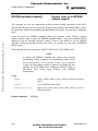
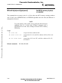
BAUD [rate]
Display or set serial baud rate
This command lets the user change the serial baud rate of the PC. This command accesses the
computer hardware directly, permitting a wider range of baud rates than the MODE command
can select. After PCbug11 executes the rate change, the new baud rate appears on the screen.
Values beyond 9600 are available; the maximum baud rate is 38,400.
Freescale Semiconductor, Inc...
Usage:
BAUD
Display current serial baud rate
BAUD 19200
Change baud rate to 19,200
NOTES
To maintain talker contact, first set the MCU baud rate to the new
value. Do this either by changing the appropriate talker code or by
using the MS command to change the MCU baud rate register
dynamically.
The default bootstrap download baud rate is 7812; the default
talker communication baud rate is 9600. You may specify different
rates when you start PCbug11 from the MS-DOS command line.
Thus, PCbug11 and talker codes work without modific-ation with
different MCU crystal frequencies. For example, to start an
MC68HC11A8 with a 4 MHz crystal, use the command PCBUG11
-A 3906. This tells PCbug11 to use half the default values for both
download and talker communication.
Changing the baud rate affects the minimum EEPROM
programming time, as the EEPROM programming algorithm relies
on the serial data transfer time.
Related commands:
M68PCBUG11/D
none
For More Information On This Product,
Go to: www.freescale.com
3-9
Freescale Semiconductor, Inc.
USING PCBUG11 COMMANDS
BF addr1 [addr2] byte|word
Block fill memory with byte or
word
This command forces an 8- or 16-bit value into address addr1 of MCU memory. If addr2 also is
specified, BF forces the value into the block of memory from address addr1 through address
addr2. If addr1 is in an EEPROM block, an EEPROM algorithm stores the value (the difference
is transparent to the user). This command includes automatic verification of the memory fill.
Freescale Semiconductor, Inc...
Usage:
BF $1000 $AA
Assign value $AA to address $1000
BF $C000 $CFFF $D3
Assign value $D3 to addresses $C000—$CFFF
BF $00 $FF $AA55
Assign alternate values $AA and $55 to addresses $00—$FF
BF $100 $120 0 1
Assign alternate values 0 and 1 to addresses $100—$120
NOTE
To set the memory value to $00, do not specify the $00 in the most
significant byte of a 16-bit value. PCbug11 interprets such a
specification as an 8-bit value, leading to incorrect MCU memory
addressing.
Related commands:
3-10
DB, MD, MS
For More Information On This Product,
Go to: www.freescale.com
M68PCBUG11/D
Freescale Semiconductor, Inc.
USING PCBUG11 COMMANDS
BL
Display breakpoints
This command displays the list of current breakpoints. The hexadecimal address of each
breakpoint appears on the screen, followed (in parentheses) by the name of any defined macro.
Usage:
Freescale Semiconductor, Inc...
BL
Related commands:
M68PCBUG11/D
Display addresses of all user-defined breakpoints
BR, NOBR
For More Information On This Product,
Go to: www.freescale.com
3-11
Freescale Semiconductor, Inc.
USING PCBUG11 COMMANDS
Freescale Semiconductor, Inc...
BR [addr [macroname]]
Display or set breakpoint [with
optional command macro
execution]
This command displays breakpoints or sets an entry in a breakpoint table. Breakpoints are set in
MCU memory only when the user starts execution of code via the G command. Before passing
control to user code, PCbug11 places an SWI instruction at every breakpoint address in the
breakpoint table. PCbug11 also handles user-placed SWIs (though using some overhead), if the
user SWI vector is downloaded from an S-record file via the LOADS command, and if there are
no breakpoints at the user SWI instructions. Note that when PCbug11 first starts, it treats the
MCU SWI vector as a user SWI vector.
If you use the BR command to set a breakpoint and you specify a macro in the macroname
option, that macro starts when code execution reaches the breakpoint. (If no such macro has
been defined, PCbug11 ignores this optional command entry.)
If you use the BR command to display breakpoints and you specify the associated macro in the
macroname option, the macro name (in parentheses) follows the breakpoint in the display. If the
macro specified is not currently defined, the macro name follows the breakpoint in the display, but
with a question-mark indicator. If no such macro is defined, the indicator "—" follows the
breakpoint in the display.
Usage:
BR
Display addresses of all user-defined breakpoints
BR $C0F1 $C045
Set breakpoints at MCU addresses $C0F1 and $C045
BR $C023 DISPREG
Set breakpoint at MCU address $C023; execute macro DISPREG
when execution reaches this breakpoint
Related commands:
3-12
BL, NOBR
For More Information On This Product,
Go to: www.freescale.com
M68PCBUG11/D
Freescale Semiconductor, Inc.
USING PCBUG11 COMMANDS
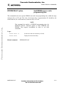
CALL addr
Execute the subroutine at addr
This command directs the monitor to execute the MCU code at addr. (The MCU code must end
with an RTS instruction.) The CALL command has the same effect as the MCU instruction JSR
<addr>; the CALL command does not affect the current state of the monitor.
Usage:
Execute the subroutine at address $100
Freescale Semiconductor, Inc...
CALL $100
Related command:
M68PCBUG11/D
G, S
For More Information On This Product,
Go to: www.freescale.com
3-13
Freescale Semiconductor, Inc.
USING PCBUG11 COMMANDS
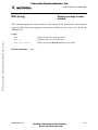
CLRM
Clear all command macros
This command removes all macro names and definitions (including the TRACE macro) from the
current library. The CLRM command does not affect libraries stored on disk via the SAVEM
command.
Usage:
Freescale Semiconductor, Inc...
CLRM
Related commands:
3-14
Clear macro names and definitions from the library
DEFM, DELM, EDITM, LOADM, LSTM, SAVEM
For More Information On This Product,
Go to: www.freescale.com
M68PCBUG11/D
Freescale Semiconductor, Inc.
USING PCBUG11 COMMANDS
CLS
Clear main window
This command clears the main window of the screen, and clears any error or
breakpoint messages.
Usage:
Clear the screen main window
Freescale Semiconductor, Inc...
CLS
Related command:
M68PCBUG11/D
KLE
For More Information On This Product,
Go to: www.freescale.com
3-15
Freescale Semiconductor, Inc.
USING PCBUG11 COMMANDS
CONTROL [parameter]
Display or change PCbug11
system parameters
Freescale Semiconductor, Inc...
This command, without the parameter option, lists all the PCbug11 parameters that the user can
modify. With a parameter specified, this command changes the parameter value. The usage
paragraph, below, shows the available parameters.
At startup, PCbug11 determines if hardware access in the communications port is possible. If so,
it uses this mode and enables direct RTS line control. If not, PCbug11 uses BIOS calls to the
COM port. The RTS line can be programmed as a write-protect logic level for systems with
external memory (see paragraph 4.4).
COM1 is the default communications port; the user can change this by adding port=2 to the
command line (as in PCBUG11 -XA port=2). PCbug11 sets up PPROG and EPROG values, to
the same address if the part operates that way. Note that the code presumes that the bit positions
of these registers are those of the 711E9 MCU.
Usage:
CONTROL HARDWARE
Access serial COM port directly through hardware
CONTROL BIOS
Access serial COM port through BIOS calls
CONTROL RTS
Control RTS directly
CONTROL PROTECT
Use RTS to provide memory write-protection
CONTROL TIMEOUT value
Specify value of serial COM timeout during input
CONTROL COM1
Use COM1 port
CONTROL COM2
Use COM2 port
CONTROL ERRMSG 0
Disable display of memory error messages
CONTROL ERRMSG 1
Enable display of memory error messages
CONTROL LAST
Toggle the last error message window on or off
CONTROL PPROG address
Change the EEPROM register address
CONTROL EPROG address
Change the EPROM register address
A special use of the CONTROL command is the BASE option, which lets you change the
PCbug11 default number base. At startup, the PCbug11 default number base is 10. To change the
default base or return to base 10, follow these examples:
CONTROL BASE HEX
Change default base to 16
CONTROL BASE DEC
Change default base back to 10
CONTROL BASE BIN
Change default base to 2
Related commands:
3-16
DEFM, LOADM, SAVEM (for details of macro libraries)
For More Information On This Product,
Go to: www.freescale.com
M68PCBUG11/D
Freescale Semiconductor, Inc.
USING PCBUG11 COMMANDS
DASM addr1 [addr2]
Disassemble from addr1 [to
addr2]
Freescale Semiconductor, Inc...
This command disassembles MCU memory, showing disassembled code in the main window. If
you specify both addr1 and addr2 values, DASM disassembles code from addr1 to addr2. If you
specify only the addr1 value, DASM starts at addr1, disassembling 15 bytes of code (plus any
additional bytes needed to finish an instruction). A special case of using only the addr1 parameter
is to give it the current value of the program counter. In this case, DASM disassembles one line of
code.
Screen display of disassembled code stops when the screen is filled. To continue the display, press
any key except ESC. To terminate disassembly, press the ESC key.
Using the DASM command is a convenient way to trace program code when using a trace macro.
Such a macro should contain the command DASM *.
Usage:
DASM $B3
Disassembles MCU addresses $B3—$C2
DASM $BF00 $BFFF
Disassembles MCU addresses $BF00—$BFFF
Related commands:
M68PCBUG11/D
ASM
For More Information On This Product,
Go to: www.freescale.com
3-17
Freescale Semiconductor, Inc.
USING PCBUG11 COMMANDS
DB startaddr [endaddr]
Display MCU memory
This command displays the contents of memory, from startaddr through endaddr. If the command
does not include an endaddr value, PCbug11 displays the contents of 15 memory loactions,
starting with startaddr.
Freescale Semiconductor, Inc...
Usage:
DB $1000
Display contents of memory addresses $1000—$100F
DB $C000 $CFFF
Display contents of memory addresses $C000—$CFFF
Related commands:
3-18
BF, MD, MS
For More Information On This Product,
Go to: www.freescale.com
M68PCBUG11/D
Freescale Semiconductor, Inc.
USING PCBUG11 COMMANDS
DEBUG
Reserved word
Freescale Semiconductor, Inc...
This command is reserved for developmental use. Do not use DEBUG as a label.
M68PCBUG11/D
For More Information On This Product,
Go to: www.freescale.com
3-19
Freescale Semiconductor, Inc.
USING PCBUG11 COMMANDS
DEFINE symbol value|address
Define a symbol
This command explicitly defines a symbol and specifies the symbol value. The symbol consists of
case-sensitive letters (abc does not equal ABC). The symbol value is a specific value or the
address of the memory location that contains the value. Such symbols can be more obviously
significant than numerical values in some contexts. PCbug11 reads such a symbol as if reading the
value. A disassembly listing shows the symbol, not the value, for better readability.
Freescale Semiconductor, Inc...
Usage:
DEFINE PORTA $1000
Define symbol PORTA = $1000
DEFINE mask1 45
Define symbol mask1 = 45 ($2D)
Related commands:
3-20
LS, UNDEF
For More Information On This Product,
Go to: www.freescale.com
M68PCBUG11/D
Freescale Semiconductor, Inc.
USING PCBUG11 COMMANDS
Freescale Semiconductor, Inc...
DEFM macrnam|TRACE|AUTOSTART
Define command, trace, or
autostart macro
This command lets the user create a command sequence (a macro) that can be executed merely by
typing the name of the macro. As many as 10 parameters can be passed to a command macro.
Within the macro, the required parameter is specified by the operator @N, where N is a singledigit number, 0—9. The syntax and use of pass parameters is the same as in Motorola assemblers.
The macrnam can be any sequence of alphanumeric characters except reserved words. More than
one macro is allowed at the same time; macros can be nested in as many as five levels. Macros are
held in macro libraries, which can be saved on disk, then reloaded as needed.
Use the main window for the macro definition. The definition may include the names of other
macros. To end the definition, press the ENTER/RETURN key on a blank line. A defined macro
can be edited within PCbug11 via the EDITM command. The macro also can be edited via a
standard text editor once the file has been saved. This is because PCbug11 saves macros in a
special text format (see LOADM). (Using the text editor is another way to define a macro, if the
definition is in the special text format.)
NOTE
If the specified macro name already exists, the new macro definition
overwrites the old.
The reserved parameter name TRACE lets the user define a macro that is executed at the
completion of every T (trace) command.
The reserved parameter name AUTOSTART lets the user define a macro that is executed
automatically during PCbug11 startup. To enable this autostart feature, use the SAVEM
command to save the macro library that contains the AUTOSTART macro. Then, from MS-DOS,
specify the macro library name as the last parameter on the command line. For example, from
PCbug11:
DEFM AUTOSTART
(Type macro definitions in main window, then press the ESC key.)
SAVEM STARTUP
QUIT (To quit PCbug11)
Then, from the PC command line:
PCBUG11 -XA STARTUP
(Loads STARTUP library, executes AUTOSTART.)
M68PCBUG11/D
For More Information On This Product,
Go to: www.freescale.com
3-21
Freescale Semiconductor, Inc.
USING PCBUG11 COMMANDS
DEFM macrnam|TRACE|AUTOSTART
Define command, trace, or
autostart macro (continued)
Freescale Semiconductor, Inc...
Usage:
DEFM CONFIG
Define macro called CONFIG
DEFM TRACE
Define macro to be executed after the T command
DEFM AUTOSTART
Define macro for automatic execution on PCbug11startup
Related commands:
3-22
CLRM, DELM, EDITM, LOADM, LSTM, SAVEM
For More Information On This Product,
Go to: www.freescale.com
M68PCBUG11/D
Freescale Semiconductor, Inc.
USING PCBUG11 COMMANDS
DELM macrnam|TRACE|AUTOSTART
Delete command, trace, or
autostart macro
This command deletes a macro definition, freeing memory space for other use.
Freescale Semiconductor, Inc...
Usage:
DELM CONFIG
Delete CONFIG macro name and definition
DELM TRACE
Delete macro name and definition used by the T command
DELM AUTOSTART
Delete autostart macro
Related commands:
M68PCBUG11/D
CLRM, DEFM, EDITM, LOADM, LSTM, SAVEM
For More Information On This Product,
Go to: www.freescale.com
3-23
Freescale Semiconductor, Inc.
USING PCBUG11 COMMANDS
DIR [mask]
Display disk directory
This command displays the contents of the current directory, or of the directory
specified by the mask parameter.
Freescale Semiconductor, Inc...
Usage:
DIR
Display contents of the current directory
DIR *.MCR
Display all current-directory files that have the extension .MCR
(macros)
DIR \
Display all files in the root directory
DIR ..\*.PAS
Display all files in the directory above the current one that have
the extension .PAS
Related command:
3-24
TYPE
For More Information On This Product,
Go to: www.freescale.com
M68PCBUG11/D
Freescale Semiconductor, Inc.
USING PCBUG11 COMMANDS
DOS [command]
Shell to DOS or execute DOS
command
Freescale Semiconductor, Inc...
This command causes PCbug11 to shell to MS-DOS. If this command includes a specified
command parameter, PCbug11 shells to MS-DOS and executes the command. Then program
control returns to PCbug11.
If this command does not have a specified command parameter, program control remains in DOS.
The simple way to return to PCbug11 is to type EXIT at the DOS prompt. Optionally, to carry
out other actions while returning to PCbug11, the user can run the program PCBUGRTN.EXE.
(The user may customize the PCBUGRTN.EXE program, as appropriate.)
If used, the program PCBUGRTN.EXE must be stored in the same directory as
PCBUG11.EXE.
Usage:
DOS COPY *.TXT a:/V
Related commands:
M68PCBUG11/D
Shell to DOS, execute command, and return to PCbug11
SHELL
For More Information On This Product,
Go to: www.freescale.com
3-25
Freescale Semiconductor, Inc.
USING PCBUG11 COMMANDS
EDITM macrnam
Edit a macro
This command lets the user edit a macro already defined and loaded into PCbug11. As many as 10
lines of the macro appear on the screen. Table 3-4 lists the EDITM edit keys.
Freescale Semiconductor, Inc...
To move from line to line, press an arrow key. There is no direct command to delete a line; after
the edit, PCbug11 automatically removes lines that contain no characters. Similarly, PCbug11
removes any leading spaces from lines.
If the named macro does not exist, the EDITM command creates the macro as a null macro. If the
user edits a null macro, only the first (blank) line of the macro appears.
Table 3-4. EDITM Edit Keys
Key
Function
Alphanumeric
If the insert function is on, inserts the new character before the
current character. If the insert function is off, replaces the current
character with the new.
Del
Deletes the character under the cursor.
Ins
Toggles the insert function on and off; default is on.
Enter
Inserts a new line after the current line.
Page down
Displays the 10 lines after the current line.
Page up
Displays the 10 lines before the current line.
Esc
Aborts the edit, without saving the macro.
F3
Stops the edit, saving changes in the macro library. (The ALT-E and
ALT-Q key combinations do the same thing.)
Usage:
EDITM macro1
Related commands:
3-26
Starts edit of the macro macro1
CLRM, DEFM, DELM, LOADM, LSTM, SAVEM
For More Information On This Product,
Go to: www.freescale.com
M68PCBUG11/D
Freescale Semiconductor, Inc.
USING PCBUG11 COMMANDS
EEPROM [startaddr [endaddr]]
Display, clear, or set EEPROM
address range(s)
Freescale Semiconductor, Inc...
This command lets the user transparently perform memory modify operations on the MCU
internal EEPROM, including the CONFIG register. Once the user enters this command with
startaddr and endaddr address values, the appropriate EEPROM programming algorithm handles
all memory write operations within that range.
If the user enters the EEPROM command without any parameter values, PCbug11 displays
memory address ranges to which the EEPROM algorithm applies. Using this command with an
address for just the startaddr parameter enables a write to that address to use the EEPROM
algorithm. Giving the startaddr parameter the value 0 is a special case: this clears all EEPROM
address ranges.
NOTE
Make sure that the startaddr—endaddr range does not include the
PPROG register; otherwise this command does not work.
Usage:
EEPROM
Display memory address ranges to which the EEPROM algorithm
applies
EEPROM 0
Clear all EEPROM address ranges
EEPROM $103F
Enable a write to address $103F to use the EEPROM algorithm
EEPROM $B600 $B6FF
Enable writes within the range $B600—$B6FF to use the
EEPROM algorithm
Related commands:
M68PCBUG11/D
EPROM
For More Information On This Product,
Go to: www.freescale.com
3-27
Freescale Semiconductor, Inc.
USING PCBUG11 COMMANDS
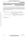
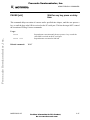
EEPROM DELAY option
Set EEPROM erase or write
programming time
This command lets the user specify EEPROM erase and write programming time, within the range
minimum-delay to 255 mS. The value of minimum-delay is approximately 120 divided by the
serial baud rate; for a 9600 baud rate, minimum-delay is 12 mS.
Freescale Semiconductor, Inc...
NOTE
This command also applies to EPROM programming time; the
EPROM DELAY command applies to both EPROM and
EEPROM. This requires coordination in order to use both
commands.
Usage:
EEPROM DELAY 20
Set the erase and write time delay to 20 mS
EEPROM DELAY
Display the current time delay
Related command:
3-28
EPROM DELAY
For More Information On This Product,
Go to: www.freescale.com
M68PCBUG11/D
Freescale Semiconductor, Inc.
USING PCBUG11 COMMANDS
EEPROM ERASE [option] [addr]
Display or change EEPROM
erase-before-write function; bulk
erase EEPROM
This command lets the user enable or disable the EEPROM byte erase-before-programming
function. The default value is enabled. The BULK option specifies bulk erasure of the EEPROM,
$B600—$B7FF, or at a specified address.
Freescale Semiconductor, Inc...
NOTES
The erase-before-programming function should be enabled before
you execute ASM, BR, T, or other commands that may modify
non-erased EEPROM.
The BULK option automatically disables the erase-beforeprogramming function. This permits the fastest downloads of Srecords to EEPROM, via the LOADS command. The bulk erase
time defaults to approximately 200 mS.
Usage:
Display EEPROM erase-before-write state
EEPROM ERASE
EEPROM ERASE DISABLE Disable erase-before-write function
EEPROM ERASE ENABLE
Enable erase-before-write function
EEPROM ERASE BULK
Bulk erase EEPROM array, starting at $B600
EEPROM ERASE BULK $E000 Bulk erase EEPROM array, starting at $E000
Related commands:
M68PCBUG11/D
none
For More Information On This Product,
Go to: www.freescale.com
3-29
Freescale Semiconductor, Inc.
USING PCBUG11 COMMANDS
EPROM [startaddr [endaddr]]
Display, clear, or set EPROM
address range(s)
Freescale Semiconductor, Inc...
This command lets the user transparently perform memory modify operations on the MCU
internal EPROM. Once the user enters this command with startaddr and endaddr address values,
the appropriate EPROM programming algorithm handles all memory write operations within that
range.
If the user enters the EPROM command without any parameter values, PCbug11 displays
memory address ranges to which the EPROM algorithm applies. Using this command with an
address for just the startaddr parameter enables a write to that address to use the EPROM
algorithm. Giving the startaddr parameter the value 0 is a special case: this clears all EPROM
address ranges.
This command affects the instructions ASM, LOADS, MOVE, MS, NOBR, and T.
NOTE
In general, the EPROM command only operates if an external
programming voltage is applied. The programming voltage should
not be present before Vcc is present or after Vcc is removed.
Usually, the programming voltage is applied to the XIRQ pin; this
prohibits use of an XIRQ talker. Consult the M68HC11 data or
information sheet before using PCbug11 with EPROM
programming.
Usage:
EPROM
Display memory address range to which the EPROM algorithm
applies
EPROM 0
Clear all EPROM address ranges
EPROM $D000 $FFFF
Enable writes within address range $D000—$FFFF to use the
EPROM algorithm
Related commands:
3-30
EEPROM
For More Information On This Product,
Go to: www.freescale.com
M68PCBUG11/D
Freescale Semiconductor, Inc.
USING PCBUG11 COMMANDS
EPROM DELAY option
Set EPROM erase or write
programming time
This command lets the user specify EPROM erase and write programming time, within the range
minimum-delay to 255 mS. The value of minimum-delay is approximately 120 divided by the
serial baud rate; for a 9600 baud rate, minimum-delay is 12 mS.
Freescale Semiconductor, Inc...
NOTE
This command also applies to EEPROM programming time; the
EEPROM DELAY command applies to both EEPROM and
EPROM. This requires coordination in order to use both
commands.
Usage:
EPROM DELAY 20
Set the erase and write time delay to 20 mS
EPROM DELAY
Display the current time delay
Related command:
M68PCBUG11/D
EEPROM DELAY
For More Information On This Product,
Go to: www.freescale.com
3-31
Freescale Semiconductor, Inc.
USING PCBUG11 COMMANDS
FIND byte|word addr1 addr2
Find all occurrences of byte or
word between addr1 and addr2
Freescale Semiconductor, Inc...
This command searches through the specified memory address range for as many as four
consecutive byte or word values. The addresses of the occurrences appear in the main window. A
byte parameter value must be in the range $00—$FF; a word parameter value must be in the
range $100—$FFFF. If the pattern contains leading zeros, the first parameter after FIND must be
the byte count of the pattern searched for.
Usage:
FIND $AA $E000 $E3FF
Find all occurrences of $AA in range $E000—$E3FF
FIND $AA55 $B600 $B7FF
Find all occurrences of $AA55 in range $B600—$B7FF (that
is, in M68C11A1 EEPROM)
FIND 2 $0012 $F800 $FFFF
Find all occurrences of $0012 in range $F800—$FFFF
FIND 3 $00 $1234 $C000 $DFFF
Related commands:
3-32
Find all occurrences of $001234 in range $C000—
$DFFF
none
For More Information On This Product,
Go to: www.freescale.com
M68PCBUG11/D
Freescale Semiconductor, Inc.
USING PCBUG11 COMMANDS
FIND mnemonic addr1 addr2
Find all occurrences of
mnemonic between addr1 and
addr2
Freescale Semiconductor, Inc...
This command searches through the specified memory address range for as many as four
characters of specific assembler code. The wild-card operator (?) in the mnemonic parameter
forces a search for the opcode only. If the mnemonic addressing mode is not an indexed one, the
symbol #, <, or > must begin the operand value. These symbols mean immediate, direct, and
extended, respectively.
NOTE
Different commands have different wild-card operators. For this
command, the wild-card operator is the question mark ( ? ).
Usage:
FIND LDAA >$1234 $E000 $E200 Find all occurrences of LDAA >$1234 in range
$E000—$E200
FIND LDAB $34,X $C230 $C560
Find all occurrences of LDAB $34,X in range
$C230—$C560
FIND LDX #? $F000 $F2FF Find all occurrences of immediate load X opcode in range
$F000—$F2FF
Related commands:
M68PCBUG11/D
none
For More Information On This Product,
Go to: www.freescale.com
3-33
Freescale Semiconductor, Inc.
USING PCBUG11 COMMANDS
G [addr]
Start user code execution
This command directs the MCU to start execution of user code at the value in the current
program counter, or at the address specified in the addr parameter.
Freescale Semiconductor, Inc...
Usage:
G
Start program execution at current program counter
G $B600
Start program execution at address $B600
Related command:
3-34
CALL, S
For More Information On This Product,
Go to: www.freescale.com
M68PCBUG11/D
Freescale Semiconductor, Inc.
USING PCBUG11 COMMANDS
HELP [command]
Display help information
This command displays help information in a temporary help window. If there is no value for the
command parameter, the default information is a general help display. If there is a command
parameter value, the information pertains to that command. Use the up-arrow, down-arrow, pageup and page-down keys to scroll through the help window. To clear the help window, press the
ESC key.
Freescale Semiconductor, Inc...
Help information is stored in a text file called PCBUG11.HLP.
Usage:
HELP
Display general help file
HELP RS
Display help file for RS command
Related commands:
M68PCBUG11/D
none
For More Information On This Product,
Go to: www.freescale.com
3-35
Freescale Semiconductor, Inc.
USING PCBUG11 COMMANDS
KLE
Kill last error message
This command clears the last-error/breakpoint window.
Usage:
Clear last error message or breakpoint from window
KLE
CLS
Freescale Semiconductor, Inc...
Related command:
3-36
For More Information On This Product,
Go to: www.freescale.com
M68PCBUG11/D
Freescale Semiconductor, Inc.
USING PCBUG11 COMMANDS
LOADM [filename [macroname]]
Load macro definitions
from default or user file
Freescale Semiconductor, Inc...
This command loads a library file of previously defined macros; the filename parameter specifies
the library file. The macros must have been stored on disk via the SAVEM command, or must
have been created via a text editor. PCbug11 checks the format of the file against the macro rules.
If the format of the specified file is valid, PCbug11 adds the library file to any existing library.
The macroname parameter specifies immediate execution of a macro in the newly loaded file. The
default extension for loading macro libraries is .MCR.
Macro files must have this text format:
DEFM macroname
BEGIN
macro-instructions
END
where macroname is the name of the macro being defined, and macro-instructions are the
PCbug11 instructions that constitute the macro. Comments, enclosed in braces ( { } ), are
allowed. Note that loading PCbug11 strips out macro comments. The symbol @ passes
parameters into macros. That is, when a macro is called, the first parameter value replaces @0,
the second parameter value replaces @1, and so forth.
Usage:
LOADM
Load macro library from default file PCBUG11.MCR
LOADM USERLIB
Load macro library from files USERLIB.MCR
LOADM A A
Load macro library from file A.MCR, and immediately execute
the macro A
Related commands:
M68PCBUG11/D
CLRM, DEFM, DELM, EDITM, LSTM, SAVEM
For More Information On This Product,
Go to: www.freescale.com
3-37
Freescale Semiconductor, Inc.
USING PCBUG11 COMMANDS
LOADS filename [loadaddr]
Load S-record file into
MCU memory
Freescale Semiconductor, Inc...
This command loads valid S1 records from the file specified by the filename parameter into MCU
memory. If the command does not have a loadaddr value, PCbug11 loads the records into the
addresses specified in the load-address field of the S-record. The filename parameter lets the user
specify any path or drive letter, according to the rules of MS-DOS. Note that this command
ignores records other than S1 records; it also ignores blank lines. An invalid format line may cause
an error message.
The loadaddr parameter lets the data be relocated during loading. During loading, to give the
monitor priority, PCbug11 traps these mode-dependent user vectors:
In bootstrap mode:
SWI — for breakpoint and trace processing
In external mode:
RESET — to start the monitor after a hardware reset
SWI — for breakpoint and trace processing
XIRQ — for the external ACIA to provide highestpriority host communication
All these vectors are available to the user, but their execution requires a slight speed overhead. If
no user breakpoints are defined, user SWI instructions are executed in real time, with no monitor
overhead. Refer to the source listings of the appropriate talker code to determine the effects of
user RESET and XIRQ on specific software.
Usage:
LOADS MYPROG
Load the S-record file MYPROG.S19 to the target addresses the
file specifies
LOADS YOURPROG.OUT
Load the S-record file YOURPROG.OUT to the target addresses
the file specifies
LOADS HISPROG $E000
Load the S-record file HISPROG.S19 offset to address $E000
Related commands:
3-38
VERF
For More Information On This Product,
Go to: www.freescale.com
M68PCBUG11/D
Freescale Semiconductor, Inc.
USING PCBUG11 COMMANDS
LS symbol
Display symbols
This command displays all currently defined symbols. The wild-card character ( * ) may only be at
the end of a symbol parameter value.
NOTE
Freescale Semiconductor, Inc...
Different commands have different wild-card operators. For this
command, the wild-card operator is the asterisk ( * ).
Usage:
LS *
Display all symbols
LS one
Display the value of symbol one
LS PORT*
Display all symbols that start with the letters PORT
Related commands:
M68PCBUG11/D
DEFINE, UNDEF
For More Information On This Product,
Go to: www.freescale.com
3-39
Freescale Semiconductor, Inc.
USING PCBUG11 COMMANDS
LSTM [mname|TRACE|AUTOSTART]
Display macro names or
definitions
This command displays all macro names in the current library, or displays the expanded definition
of a specified macro. If such a definition includes the names of other macros, each nested level is
indented in the screen display.
Freescale Semiconductor, Inc...
Usage:
LSTM
Display names of all macros in the current directory
LSTM CONFIG
Display the definition of the macro CONFIG
LSTM TRACE
Display the definition of the macro used after execution of the
TRACE command
LSTM AUTOSTART
Display the definition of the macro AUTOSTART
Related commands:
3-40
CLRM, DEFM, DELM, EDITM, LOADM, SAVEM
For More Information On This Product,
Go to: www.freescale.com
M68PCBUG11/D
Freescale Semiconductor, Inc.
USING PCBUG11 COMMANDS
MD startaddr [endaddr]
Display MCU memory
This command displays the contents of memory, from startaddr through endaddr. If the command
does not include an endaddr value, PCbug11 displays the contents of 15 memory locations,
starting with startaddr.
Freescale Semiconductor, Inc...
Usage:
MD $1000
Display contents of memory addresses $1000—$100F
MD $C000 $CFFF
Display contents of memory addresses $C000—$CFFF
Related commands:
M68PCBUG11/D
BF, DB, MS
For More Information On This Product,
Go to: www.freescale.com
3-41
Freescale Semiconductor, Inc.
USING PCBUG11 COMMANDS
MM addr
Modify memory from addr
This command lets the user modify memory contents, starting at the specified address. After
changing a value, press return to move to the next address. To step through memory without
changing values, press return repeatedly, or press the up-arrow or down-arrow keys. To modify a
memory value without stepping to the next address, include the character = on the command line.
To end the memory-modify operation, press the ESC key or end the command line with a period.
Freescale Semiconductor, Inc...
If the memory area already has been defined as EEPROM or EPROM, the modify is
transparent to the user.
NOTE
The MM command accepts only hexadecimal values. It does not
accept any values after a period.
Usage:
MM $100
Related commands:
3-42
Modify memory from address $100
BF, DB, MD, MS
For More Information On This Product,
Go to: www.freescale.com
M68PCBUG11/D
Freescale Semiconductor, Inc.
USING PCBUG11 COMMANDS
MOVE addr1 addr2 addr3
Move memory between addr1
and addr2 to addr3
This command moves memory contents between addr1 and addr2 to addr3, without altering the
contents. If the memory area already has been defined as EEPROM or EPROM, the move is
transparent to the user.
Usage:
Freescale Semiconductor, Inc...
MOVE $100 $150 $200
Related command:
M68PCBUG11/D
Move $50 bytes from $100 to $200
none
For More Information On This Product,
Go to: www.freescale.com
3-43
Freescale Semiconductor, Inc.
USING PCBUG11 COMMANDS
MS addr byte|word [byte|word]
Set MCU memory byte(s)
or word(s)
This command forces as many as nine 8- or 16-bit values into MCU memory, starting at address
addr. If addr is in an EEPROM block, an EEPROM algorithm stores the value (the difference is
transparent to the user).
Freescale Semiconductor, Inc...
NOTE
To set the memory value to $00, do not specify the $00 in the most
significant byte of a 16-bit value. PCbug11 interprets such a
specification as an 8-bit value, leading to incorrect MCU memory
addressing.
Usage:
MS $1000 $AA
Assign value $AA to address $1000
MS $C000 $1234 $56
Assign values $12, $34, and $56 to addresses $C000, $C001, and
$C002
MS $50 $55AA $FF00
Assign values $55, $AA, $FF, and $00 to addresses $50, $51,
$52, and $53
Related commands:
3-44
BF, DB, MD, MM
For More Information On This Product,
Go to: www.freescale.com
M68PCBUG11/D
Freescale Semiconductor, Inc.
USING PCBUG11 COMMANDS
MSG [string]
Display message in main
window
This command displays the string parameter value on the screen. Alternatively, this command
toggles the RTS line (power supply or write-protect control); use the string value ^P for this
alternative role.
Freescale Semiconductor, Inc...
Usage:
MSG
Display a blank line in the main window
MSG ^P
Toggle the logic level on the RTS line
MSG Hello World
Display the message Hello World in the main window
Related commands:
M68PCBUG11/D
none
For More Information On This Product,
Go to: www.freescale.com
3-45
Freescale Semiconductor, Inc.
USING PCBUG11 COMMANDS
NOBR [address]
Remove all or specified
breakpoints
Freescale Semiconductor, Inc...
This command removes the specified breakpoint from the internal breakpoint table. If there is no
address parameter value, this command removes all breakpoints from the table and restores the
SWI vector to its previous state. (This implies that if a user SWI vector previously has been
installed via the LOADS command or was detected upon PCbug11 startup, then user SWIs run in
real time without intervention by PCbug11.)
Usage:
NOBR
Remove all breakpoints and restore previous SWI vector
NOBR $E034
Remove breakpoint at address $E034
Related command:
3-46
BL, BR
For More Information On This Product,
Go to: www.freescale.com
M68PCBUG11/D
Freescale Semiconductor, Inc.
USING PCBUG11 COMMANDS
PAUSE [mS]
Wait for any key press or delay
time
This command delays execution of a macro until a specified time elapses, until the user presses a
key, or until the byte value $4B is received on the PC serial port. This lets the target MCU control
the execution of PCbug11 macro commands.
Freescale Semiconductor, Inc...
Usage:
PAUSE
Suspend macro execution until the user presses a key or until the
value $4B is received on the PC serial port
PAUSE 1000
Suspend macro execution for 1000 mS
Related command:
M68PCBUG11/D
WAIT
For More Information On This Product,
Go to: www.freescale.com
3-47
Freescale Semiconductor, Inc.
USING PCBUG11 COMMANDS
PRINT
Display PCbug11 version
number
This command displays the PCbug11 startup message, which includes the Motorola
copyright message and the revision number.
Usage:
Display the revision number
Freescale Semiconductor, Inc...
PRINT
Related command:
3-48
VER
For More Information On This Product,
Go to: www.freescale.com
M68PCBUG11/D
Freescale Semiconductor, Inc.
USING PCBUG11 COMMANDS
PROTECT [startaddr [endaddr]]
Display, clear, or set writeprotected address range(s)
Freescale Semiconductor, Inc...
If this command has no parameter values, it displays the ranges of write-protected memory. If this
command has the parameter value 0, it clears all write-protected memory ranges. If this command
has other parameter values, it inhibits PCbug11 from writing to any internal or external MCU
memory location: any subsequent PCbug11 memory modify attempt causes an error message
instead of a memory modification.
Note, however, that the PROTECT command does not inhibit the user's own MCU code.
Usage:
PROTECT
Displays all write-protected memory address ranges
PROTECT 0
Clears all write-protected memory address ranges
PROTECT $102B
Prevents PCbug11 from writing to the BAUD register
PROTECT $FFC0 $FFFF
Prevents PCbug11 from changing any MCU vectors
Related commands:
M68PCBUG11/D
none
For More Information On This Product,
Go to: www.freescale.com
3-49
Freescale Semiconductor, Inc.
USING PCBUG11 COMMANDS
QUIT [Y]
Terminate PCbug11 session
[without confirming]
This command terminates the PCbug11 session. If this command includes the Y parameter,
termination happens at once. If this command does not include the Y parameter, a prompt asks for
user confirmation before terminating the session.
Freescale Semiconductor, Inc...
Note that termination of the PCbug11 session does not check that breakpoints are cleared or that
macros are saved.
Usage:
QUIT
Terminates PCbug11 session after user confirmation
QUIT Y
Terminates PCbug11 session immediately
Related commands:
3-50
none
For More Information On This Product,
Go to: www.freescale.com
M68PCBUG11/D
Freescale Semiconductor, Inc.
USING PCBUG11 COMMANDS
RD [T]
Display or trace MCU regisiters
If this command does not include the T parameter, it displays, in the register window, the current
value of the MCU registers. If this command does include the T parameter, register values appear
in the main window, so the user can see a continuous register trace.
Freescale Semiconductor, Inc...
The user may execute this command while the MCU executes user code. Careful use of both
forms of this command let the user freeze the MCU state at a particular point (via RD) while
displaying the newest state (via RD T).
Usage:
RD
Display current MCU register values in the register window
RD T
Display register values in the main window
Related commands:
M68PCBUG11/D
RM, RS
For More Information On This Product,
Go to: www.freescale.com
3-51
Freescale Semiconductor, Inc.
USING PCBUG11 COMMANDS
RESET [addr]
MCU hardware reset with
existing or new reset vector
Freescale Semiconductor, Inc...
This command directs the MCU to generate a hardware reset. The MCU also starts execution of
user code at the addr value, if this parameter is part of the command (or if a previous RESET
command contained an addr value).
Once the reset occurs, the default implementation of PCbug11 re-initializes the talker code. Then
the MCU idles, if no addr value was specified. If an addr value was specified, talker code jumps
to that address. Note that once a RESET command specifies an addr value, the PC retains that
value until another RESET command specifies a different addr value.
Refer to the appropriate talker code source listing for details.
The RESET command first instructs the MCU to generate an internal reset, via the clock monitor
fail detector. This internal reset forces the external RESET pin low, stimulating the external
hardware reset. To trip the clock monitor fail detector, PCbug11 downloads and executes this
code in a reserved area of RAM:
STY cme_jmp
clock monitor fail jump address
STAA OPTION,X
OPTION=$39
STAB TEST1,X
TEST1=$3E
STOP
JMP user_start
<- in case STOP does not generate clock
monitor enable (CME) reset
where Y = user reset address, X = $1000 (the default I/O register base address for the MCU), and
ACCA = $08 (enables the clock monitor in the OPTION register).
The values passed to ACCB, CCR, and Y depend on the MCU type and operating mode:
3-52
•
Bootstrap mode: For an A8 MCU only, set ACCB = 0 to clear the DISR bit of the
TEST1 register. For all other MCUs, set ACCB = 4 to force the clock monitor reset
by setting the FCM bit of the TEST1 register. For all devices, set CCR = $40 to
enable the STOP instruction and enable I-bit interrupts. This value also disables XIRQ,
permitting execution of the instruction after STOP if all else fails. The user reset
address is $0000.
•
Expanded mode: For all MCUs, the TEST1 register is not accessible, so set ACCB =
$0. Set CCR = $40 to enable the STOP and XIRQ and disable I-bit interrupts. The
user defines the reset address in the appropriate TALKERXX.MAP file.
For More Information On This Product,
Go to: www.freescale.com
M68PCBUG11/D
Freescale Semiconductor, Inc.
USING PCBUG11 COMMANDS
RESET [addr]
MCU hardware reset with existing
or new reset vector
(continued)
This command starts with an internal reset. This internal reset is like an external hardware reset,
except that the MCU uses the COP clock vector instead of the RESET vector (provided that
external capacitance does not delay the rising edge of the reset output signal). Refer to the
M68HC11 data book and user manual for details.
Freescale Semiconductor, Inc...
Usage:
RESET
Force the MCU to reset and run code from the default address or
the address previously supplied
RESET $B600
Force the MCU to reset and run code from address $B600
Related commands:
M68PCBUG11/D
none
For More Information On This Product,
Go to: www.freescale.com
3-53
Freescale Semiconductor, Inc.
USING PCBUG11 COMMANDS
RESTART [option]
Restart PCbug11 with same or
new option
This command performs a complete restart of the monitor. This command is equivalent to the
MS-DOS command PCBUG11 option, but retains command macros. Assembler macros and
symbols are lost.
Freescale Semiconductor, Inc...
RESTART is useful should a complete communication failure occur, or if the MCU is given an
external hardware reset in bootstrap mode.
Usage:
RESTART
Restart the monitor with the option specified during first
execution of PCbug11
RESTART -XE
Restart the monitor with the -XE option (equivalent to the
command PCBUG11 -XE)
Related commands:
3-54
none
For More Information On This Product,
Go to: www.freescale.com
M68PCBUG11/D
Freescale Semiconductor, Inc.
USING PCBUG11 COMMANDS
RM
Modify MCU registers in window
Freescale Semiconductor, Inc...
This command lets MCU registers be modified in the register window, via the normal keyboard
editing keys. Each register field is in its own section of the window. To move within and between
fields, use these keys:
Up arrow
Move back one field
Down arrow
Move forward one field
Left arrow
Move backwards in current field
Right arrow
Move forward in current field
Ins
Insert at cursor position
Del
Delete at cursor position
Return
Quit register edit; update all MCU registers
Esc
Quit register edit; do not change MCU registers
Note that all fields but SXHINZVC can be edited in binary, decimal, or hexadecimal format.
SXHINZVC can be edited in binary format only. At the end of the edit, PCbug11 automatically
runs the RD command to confirm any register changes.
Usage:
Begin editing register window
RM
Related commands:
M68PCBUG11/D
RD, RS
For More Information On This Product,
Go to: www.freescale.com
3-55
Freescale Semiconductor, Inc.
USING PCBUG11 COMMANDS
RS register value
Set value of MCU register
This command lets the user force the value of any one MCU register, updating the register
window. Valid options for the register are: PC, ACCA, ACCB, X, Y, CCR, and SP.
Usage:
Assign value $61 to MCU accumulator A
Freescale Semiconductor, Inc...
RS ACCA $61
Related commands:
3-56
RD, RM
For More Information On This Product,
Go to: www.freescale.com
M68PCBUG11/D
Freescale Semiconductor, Inc.
USING PCBUG11 COMMANDS
S
Stop user code execution
This command directs the MCU to stop executing user code.
Usage:
S
CALL, G
Freescale Semiconductor, Inc...
Related command:
Stop program execution
M68PCBUG11/D
For More Information On This Product,
Go to: www.freescale.com
3-57
Freescale Semiconductor, Inc.
USING PCBUG11 COMMANDS
SAVEM [filename]
Save macro definitions in user
or default file
Freescale Semiconductor, Inc...
This command saves on disk the library of macros created via the DEFM command, appending
the extension .MCR to each file. The macro files are normal text files that may be edited with
standard text editors. But the macros must remain in the special macro format in order to be
reloaded into PCbug11. (The explanation of the LOADM command explains this format.) If the
SAVEM command does not have a filename parameter, PCbug11 uses the default name
PCBUG11.
NOTE
Be careful about saving a library to the same file the library was
loaded from. As PCbug11 strips out comments, saving the loaded
file back to the same library overwrites the original files with the
no-comment equivalents.
Usage:
SAVEM USERLIB
Save macro library in file USERLIB.MCR
SAVEM
Save macro library in default file PCBUG11.MCR (equivalent to
command SAVEM PCBUG11)
Related commands:
3-58
CLRM, DEFM, DELM, EDITM, LOADM, LSTM
For More Information On This Product,
Go to: www.freescale.com
M68PCBUG11/D
Freescale Semiconductor, Inc.
USING PCBUG11 COMMANDS
SHELL [command]
Shell to DOS or execute DOS
command
Freescale Semiconductor, Inc...
This command causes PCbug11 to shell to MS-DOS. If this command includes a specified
command parameter, PCbug11 shells to MS-DOS and executes the command. Then program
control returns to PCbug11.
If this command does not have a specified command parameter, program control remains in DOS.
The simple way to return to PCbug11 is to type EXIT at the DOS prompt. Optionally, to carry
out other actions while returning to PCbug11, the user can run the program PCBUGRTN.EXE.
(The user may customize the PCBUGRTN.EXE program, as appropriate.) If used, the program
PCBUGRTN.EXE must be stored in the same directory as PCBUG11.EXE.
Usage:
SHELL COPY *.TXT a:/V
Related command:
M68PCBUG11/D
Shell to DOS, execute command, and return to PCbug11
DOS
For More Information On This Product,
Go to: www.freescale.com
3-59
Freescale Semiconductor, Inc.
USING PCBUG11 COMMANDS
T [addr]
Trace user code
This command single-step traces program code from the address specified by the addr parameter
to the next logical address. If the command does not have an addr parameter value, tracing begins
from the address in the program counter. This command places an SWI at the next executable
address or addresses. If a command macro called TRACE has been defined, PCbug11 executes
this macro automatically at the completion of the T command.
Freescale Semiconductor, Inc...
A useful trace macro is:
RD
DASM *
If the next executable instruction involves a branch to the current address, the trace is disabled to
allow the instruction to execute. However, PCbug11 still displays the TRACE state. As the talker
is interrupt driven, this does not cause any monitor problem; all PCbug11 commands remain
available.
Usage:
T
Trace program code from program-counter address
T $100
Trace program code from address $100
Related commands:
3-60
none
For More Information On This Product,
Go to: www.freescale.com
M68PCBUG11/D
Freescale Semiconductor, Inc.
USING PCBUG11 COMMANDS
TERM [X1 Y1 X2 Y2]
Simple windowed terminal
emulator
Freescale Semiconductor, Inc...
If this command has no parameter values, it starts a simple terminal emulator at the currently
defined window coordinates. The optional parameter values X1, Y1, X2, and Y2 redefine the
window:
X1
Left column
Y1
Top row
X2
Right column
Y2
Bottom row
If any parameter value is used, all must be used. Once these values are specified in a TERM
command, they remain in force until replaced in another TERM command.
To quit the terminal emulator, press the Esc key.
Usage:
TERM
Open terminal emulator at default or at coordinates previously
specified
TERM 0 0 20 20
Open terminal emulator in a window 20 columns by 20 rows, at
the upper left corner of the screen
Related commands:
M68PCBUG11/D
none
For More Information On This Product,
Go to: www.freescale.com
3-61
Freescale Semiconductor, Inc.
USING PCBUG11 COMMANDS
TYPE filename
Display disk file in main window
This command displays the contents of the specified file. Standard DOS path names apply.
Freescale Semiconductor, Inc...
Usage:
TYPE RUNTIME.MCR
Display file RUNTIME.MCR, from the current directory
TYPE \TEMP.BIT
Display file TEMP.BIT, from the root directory
TYPE ..\LIST.PAS
Display file LIST.PAS from the directory above the current
directory
Related command:
3-62
DIR
For More Information On This Product,
Go to: www.freescale.com
M68PCBUG11/D
Freescale Semiconductor, Inc.
USING PCBUG11 COMMANDS
UNDEF symbol
Undefine a symbol
This command removes a symbol from the symbol table list. The wild-card character ( * ) may
only be at the end of a symbol parameter value.
NOTE
Freescale Semiconductor, Inc...
Different commands have different wild-card operators. For this
command, the wild-card operator is the asterisk ( * ).
Usage:
UNDEF one
Clear the symbol one
UNDEF PORT*
Clear all symbols that start with the letters PORT
UNDEF *
Clear all symbols
Related commands:
M68PCBUG11/D
DEFINE, LS
For More Information On This Product,
Go to: www.freescale.com
3-63
Freescale Semiconductor, Inc.
USING PCBUG11 COMMANDS
VER
Display PCbug11 version
number
This command displays the PCbug11 startup message, which includes the Motorola
copyright message and the revision number.
Usage:
Display the revision number
Freescale Semiconductor, Inc...
VER
Related command:
3-64
PRINT
For More Information On This Product,
Go to: www.freescale.com
M68PCBUG11/D
Freescale Semiconductor, Inc.
USING PCBUG11 COMMANDS
VERF filename [memaddr]
Verify S-record disk file against
memory
Freescale Semiconductor, Inc...
This command verifies contents of S1 records in the specified file against MCU memory at the
specified memaddr address. If this command does not have a memaddr address, it verifies the S1
records against MCU memory at the addresses specified in the S1-record load address fields.
The default extension of filename is .S19. The default path is the current working directory, but
the user may specify any path or drive letter according to the rules of MS-DOS. Note that this
command ignores blank lines. An invalid format line may cause an error message.
Usage:
VERF MYPROG
Verify the S-record file MYPROG.S19 at the target addresses
specified in the file
VERF YOURPROG.OUT
Verify the S-record file YOURPROG.OUT at the target
addresses specified in the file
VERF HISPROG $E000
Verify the S-record file HISPROG.S19 offset at address $E000
Related commands:
M68PCBUG11/D
LOADS
For More Information On This Product,
Go to: www.freescale.com
3-65
Freescale Semiconductor, Inc.
USING PCBUG11 COMMANDS
VERF ERASE addr1 [addr2]
Verify that memory contains $FF
This command verifies erasure of the specified memory range, that is that memory blocks in the
range contain the value $FF. If this command contains only an addr1 value, only the addr1 byte is
checked. After executing this command, PCbug11 lists any memory locations not erased.
Freescale Semiconductor, Inc...
Usage:
VERF ERASE $100
Verify that block $100 is erased
VERF ERASE $E000 $FFFF
Verify that range $E000—$FFFF is erased
Related commands:
3-66
none
For More Information On This Product,
Go to: www.freescale.com
M68PCBUG11/D
Freescale Semiconductor, Inc.
USING PCBUG11 COMMANDS
VERF SET addr1 addr2 value
Verify that memory contains the
value
This command verifies that the specified memory range contains the specified single-byte value.
After executing this command, PCbug11 lists any memory locations that do not contain the value.
Usage:
Freescale Semiconductor, Inc...
VERF SET $100 $1FF $35
Related command:
M68PCBUG11/D
Verify that range $100—$1FF contains the value $35
none
For More Information On This Product,
Go to: www.freescale.com
3-67
Freescale Semiconductor, Inc.
USING PCBUG11 COMMANDS
WAIT [mS]
Wait for ms
This command delays execution of a macro until a specified time elapses, until the user presses a
key, or until the byte value $4B is received on the PC serial port. This lets the target MCU control
the execution of PCbug11 macro commands.
Freescale Semiconductor, Inc...
Usage:
WAIT
Suspend macro execution until the user presses a key or until the
value $4B is received on the PC serial port
WAIT 1000
Suspend macro execution for 1000 mS
Related command:
3-68
PAUSE
For More Information On This Product,
Go to: www.freescale.com
M68PCBUG11/D
Freescale Semiconductor, Inc.
ADVANCED TOPICS
CHAPTER 4
ADVANCED TOPICS
Freescale Semiconductor, Inc...
4.1 INTRODUCTION
This chapter consists of more detail about advanced PCbug11 topics, including
macros, trace, breakpoints, and talkers.
4.2 MACROS
A useful PCbug11 feature is letting the user execute a common command sequence by typing a
single instruction: a macro.
You may define macros either in PCbug11 or via an external text editor. It is possible to define
more than one macro while using PCbug11. The area where macros are held is the macro library.
Macros have two main elements: names and definitions. A macro name is a sequence of as many
as 80 letters, except for character sequences that form PCbug11 reserved commands. To run a
macro, enter its name, just as you would any PCbug11 command.
A macro definition consists of the commands, in order, that make up the macro. A macro
definition can include other macros: a macro can call another macro (but the macro cannot call
itself). This nesting of macros can be as deep as five levels.
Macro definitions can include as many as 10 parameters. When the macro is called, the parameter
values in the calling statement or command take the place of the parameters in the definitions. The
symbol @, followed by a digit, denotes a parameter in a macro definition: @0 denotes the first
parameter, @1 denotes the second parameter, and so forth, through @9 for the tenth parameter.
M68PCBUG11/D
For More Information On This Product,
Go to: www.freescale.com
4-1
Freescale Semiconductor, Inc.
ADVANCED TOPICS
Freescale Semiconductor, Inc...
The only limit to the PCbug11 macro library is the amount of computer memory. There is no limit
on the number of macros, so long as their collective definitions do not exceed the memory-size
limit. Defining a new macro that has the same name as a previous macro deletes the previous
macro (a warning message alerts the user before PCbug11 carries out the deletion.)
Terminating PCbug11 eliminates the macro library. However, you may store the macro library on
a disk before terminating PCbug11, for reloading the next time you activate PCbug11. Macros are
stored on disk in a special format; PCbug11 generates this format automatically for macros
defined in PCbug11. You may edit stored macros, via a standard text editor, provided you retain
the special format. Reloading a stored macro library adds all macros of that file to the current
macro library.
4.2.1
Defining Macros
There are two ways to define macros. One way is to define the macro within PCbug11: type
DEFM, followed by the name of the new macro. PCbug11 then accepts command lines from the
user, placing these lines in the macro library under the macro name. This is the quickest and
easiest way to define macros.
Another way to define macros is to write definitions in text files, in a standard format. (The
DEFM command explanation, in Chapter 3, shows this format.) The first line of such a macro
must contain DEFM, followed by the macro name. The second line is the one word BEGIN. Any
number of subsequent lines, each containing a command (and possible parameters), follow the
BEGIN line. The last line of the macro is the one word END. Any line of the macro may include a
comment, enclosed in braces ( { } ); PCbug11 ignores comments.
For example, this is the definition of a macro named RUNIT:
DEFM RUNIT
BEGIN
{Macro definition}
LOADS @0
{Load the S-record the first parameter names}
VERF @0
{Verify the S-record}
G @1
{Run a program at the second parameter}
END
Once defined and loaded, this macro lets the user load, verify, and run a program with one
command. To load and verify the S-record TRYIT.S19, then run the S-record from address
$E000, the user enters only:
RUNIT TRYIT $E000
4-2
For More Information On This Product,
Go to: www.freescale.com
M68PCBUG11/D
Freescale Semiconductor, Inc.
ADVANCED TOPICS
4.2.1.1 Autostart Macros
Automatic macro loading is possible when you run PCbug11 from the DOS prompt. To arrange
this, include the macro= option in the command line. If the specified macro library contains
AUTOSTART, the macro runs before the user begins work.
Freescale Semiconductor, Inc...
The autostart macro can receive parameter values passed from the command line. For example,
this AUTOSTART macro verifies that a certain area of MCU memory is erased (that is, contains
the value $FF):
DEFM AUTOSTART
BEGIN
VERF ERASE @0 @1
END
If this macro is stored in a macro library file called CHECK, the user can verify EEPROM erasure
of an M68HC11E9 MCU by entering this runtime command:
PCBUG11 -XE MACRO=CHECK ($B600 $B6FF)
Once PCbug11 starts, the macro AUTOSTART runs automatically, using the
parameter values in parentheses from the runtime command.
4.2.1.2 Null Macros
A null macro is one that does not contain any commands. A null macro is a useful reminder for
development work, when a macro will be needed, but its exact operation is not yet clear. A null
macro can be run, saved, stored, and deleted, just as any other macro. The definition for such a
null macro is:
DEFM macro1
BEGIN
END
4.2.2
Editing Macros
There are two ways to edit a macro. One way is to use the EDITM command, which lets the user
alter a macro from within PCbug11. The EDITM entry of Chapter 3 explains more about such
editing.
The other way to edit a macro is to do so in a text file, using any standard text editor. This
method lets the user include comments in the file. Macros in text files may be regarded as source
files for PCbug11. In fact, PCbug11 uses an interpreter, not a compiler, to run macros, but text
files are easier to maintain than libraries created within PCbug11. Note that the DOS command
lets the user work on macro text files without having to exit and restart PCbug11.
M68PCBUG11/D
For More Information On This Product,
Go to: www.freescale.com
4-3
Freescale Semiconductor, Inc.
ADVANCED TOPICS
4.2.3
Listing and Clearing Macros
Macros are stored dynamically in the computer memory, so they use only as much memory as
they need. Eventually, the computer may run out of memory. This is the case if PCbug11 no
longer permits definitions or loading of macros. To make room for new macros, the user must
delete some of the present ones from memory. If such macros will be needed again, the user
should save them to a disk file, via the SAVEM command.
Freescale Semiconductor, Inc...
There are two ways to delete macros. Use the CLRM command to remove all macros at the same
time. Use the DELM command to delete a single macro.
Remember that loading a macro that has the same name as a previous macro automatically
replaces the previous macro with the new. This is not the case for macro definitions via the
DEFM command, which confirms that the user wants to replace such a previous macro.
4.3 USING TRACE AND BREAKPOINTS
Having a program stop upon reaching a certain address is a useful feature for any development
system; such an address is a breakpoint. An associated feature is having the program stop as soon
as it executes the current command; this is tracing.
4.3.1
Breakpoints
The user can arrange for a program to stop at a specified location by placing a breakpoint at the
location. Once the program stops, the user can examine registers and memory locations to verify
that the program has performed as expected.
Use the BR command to place a breakpoint; use the NOBR command to remove breakpoints.
The BR command lets you specify a macro to be run automatically when the program reaches the
breakpoint. This feature is helpful if a series of commands is to be executed every time the
breakpoint is reached.
To implement breakpoints, PCbug11 substitutes the M68HC11 software interrupt (SWI)
instruction for the program instruction at the breakpoint address. This has two important
implications:
1. The program must be in alterable memory, such as RAM or EEPROM. It is not
possible to install breakpoints in a program in ROM. Should a user try to place a
breakpoint in ROM, a warning message appears. Before replacing the program
instruction (with an SWI instruction), PCbug11 records the program instruction. This
lets PCbug11 return the program to its original state when the breakpoint operation is
complete.
4-4
For More Information On This Product,
Go to: www.freescale.com
M68PCBUG11/D
Freescale Semiconductor, Inc.
ADVANCED TOPICS
2. PCbug11 must be able to alter the SWI interrupt vector. Consequently, this vector
also must be in alterable memory. The SWI interrupt vector points to an appropriate
interrupt-handling routine in the talker. The SWI instruction forces the program being
run to enter that specified interrupt-handling routine.
Should either the program or the SWI interrupt vector not be in alterable memory,
the breakpoint function of PCbug11 cannot be used.
Freescale Semiconductor, Inc...
When the breakpoint function is available, the sequence of events is:
1. The user enters the BR command to set a breakpoint. PCbug11 records the default
SWI vector, then replaces that vector with a value that points to a routine in the talker.
2. The user enters the G or CALL command to run the program. PCbug11 records the
contents of each breakpoint location, replaces the contents with an SWI instruction,
and runs the program.
3. When the program reaches a breakpoint, the talker routine that handles SWI interrupts
notifies PCbug11 of the interrupt. PCbug11 then replaces all breakpoint SWI
instructions with original memory contents, displays BREAK on the computer screen,
and runs any macro defined for the breakpoint reached.
4. If the user stops the program (via the S command) before the program reaches a
breakpoint, original memory contents replace all breakpoint SWI instructions.
5. When the user deletes all breakpoints (via the NOBR command), PCbug11 replaces
the talker SWI vector with the original SWI vector.
NOTES
From this sequence, it is clear that a system reset before step 5
could leave in memory unreplaced SWI instructions and the talker
SWI vector. If the system must be reset during a breakpoint
operation, be sure to reload the program to restore memory
contents.
PCbug11 also permits SWI instructions in user code. Whenever
program execution arrives at such an instruction, PCbug11
compares the instruction's address to the addresses of all
breakpoints set. If there is no match, PCbug11 recalls the user's
SWI vector and runs the program at that address. This arrangement
entails additional overhead for a user SWI interrupt.
M68PCBUG11/D
For More Information On This Product,
Go to: www.freescale.com
4-5
Freescale Semiconductor, Inc.
ADVANCED TOPICS
4.3.2
Tracing
Freescale Semiconductor, Inc...
A user who steps through a program, instruction by instruction, is tracing the program. A user
could implement tracing by placing breakpoints after all assembly commands, but this would be
very time-consuming for the user. PCbug11 implements automatic tracing via its trace (T)
command.
The user may notice that tracing takes longer than other PCbug11 operations. This is because
tracing is complex: for each step, PCbug11 must find the address of the next opcode. This entails
disassembling the opcode at the current address to determine the number of following bytes. The
process is complicated for a jump opcode, and even more so for a branch opcode. Usually, in
tracing, an SWI replaces the next opcode in the program. For a jump, the destination opcode must
be replaced. For a branch, two opcodes must be replaced: the one following the branch instruction
and the one at the branch destination.
Once the SWI is placed in memory, PCbug11 runs the program. The second instruction is an
SWI, so the program stops. Again, PCbug11 must be able to amend the SWI vector and the
program memory. The user may specify a macro to be executed when a program reaches a trace
SWI. Such a macro may contain any instructions, but must be named TRACE. Typically, a
TRACE macro disassembles the current instruction and reads registers. The TRACE macro can
even contain the trace (T) command; in this case, the program steps through all its instructions
until stopped by the user or until it arrives at a self loop.
A self loop is a program jump or branch to its current location. Tracing is pointless for a self loop,
so the program continues to run, displaying the status TRACING, until the user stops execution
or until the branch condition is met or failed.
4.4 TALKERS IN EEPROM OR EXTERNAL MEMORY
For many users, the easiest way to make a talker available is to use a boot option: the talker
program is downloaded every time the user hardware is used. But there are two potential
disadvantages to this approach:
1. Any problem in transfering the talker from the computer to the hardware prevents the
talker from working.
2. The talker uses MCU internal RAM. As some MCUs have 256 or fewer bytes of
RAM, the talker, stack, and interrupt vectors leave little room for user programs or
data.
An alternative approach is to install the talker in the internal EEPROM of the MCU or in an
external memory. Then, whenever the package is run it is not necessary to download the talker
program to the hardware. Furthermore, as the talker does not reside in RAM, more RAM space
remains available for user programs and data.
4-6
For More Information On This Product,
Go to: www.freescale.com
M68PCBUG11/D
Freescale Semiconductor, Inc.
ADVANCED TOPICS
Freescale Semiconductor, Inc...
To load a talker into EEPROM, first boot up the MCU normally, then define the EEPROM area.
Next, install the talker via the LOADS instruction and verify the installation via the VERF
command. Once verified, the talker is ready for use. Per paragraph 4.6, you should terminate
PCbug11, then run it again, selecting the correct .MAP file instead of the boot option.
TALKEREE is a special talker that already uses the internal EEPROM. Two files must be
available to make TALKEREE available: TALKEREE.S19 and TALKEREE.MAP. The .S19 is
the S-record format of the talker to be installed in EEPROM; this must be in the current user
directory. The .MAP file is a list of addresses that PCbug11 uses for communication with the
board; this file must be in the user's current working directory. (When the boot option is used,
PCbug11 automatically handles this information, so no external .MAP file is required.)
For example, this macro programs the talker into the EEPROM of an M68HC11E9
MCU:
DEFM AUTOSTART
BEGIN
MS $1035 0
{Run this macro automatically}
{Clear BPROT register — not
needed for A8}
EEPROM $B600 $B7FF {Enable EEPROM algorithm}
LOADS TALKEREE
{Load talker into EEPROM}
VERF TALKEREE
{Verify loading}
QUIT Y
{Exit PCbug11}
END
Saving this macro in a file called STARTUP.MCR makes this sequence possible to
run the EEPROM talker:
1. Start up PCbug11 by typing: PCBUG11 -E STARTUP
2. Reset board
3. Start up PCbug11 by typing: PCBUG11 TALKEREE
M68PCBUG11/D
For More Information On This Product,
Go to: www.freescale.com
4-7
Freescale Semiconductor, Inc.
ADVANCED TOPICS
NOTES
If any error messages appear when you run the macro, press the
capital S key to stop the macro, and correct the errors.
Freescale Semiconductor, Inc...
Using the macro and startup sequence above leaves most of the
RAM free for user programs. The default stack for TALKEREE is
at $3F, so avoid using RAM between $00 and $3F. To move the
stack, modify the source file TALKEREE.ASC by changing the
value of the symbol STACK.
The interrupt vector jumps are in the $C4 — $FD area of RAM.
The jumps are initialized with safe values for PCbug11. The JMP
instructions may be modified by the user, but the user should not
modify the XIRQ interrupts that PCbug11 uses. User code should
not be in the $C4 — $FD area. It may be a good idea to set up the
necessary interrupt vectors, then run the PROTECT command, per
Chapter 3.
If the board in use includes external memory, you can use the RTS communications port line to
provide a limited write-protection facility. The RTS line carries a standard RS-232 signal that
must be converted to a TTL logic level for use with the MCU. If the signal is directly controllable
(see the CONTROL command explanation in Chapter 3), you can combine the signal logically
with the MCU R/W signal to protect memory. When PCbug11 accesses memory, it forces the
RTS line high, permitting the write to memory. But when the program itself tries to access
memory, the RTS line remains low, preventing such access.
4.5 PROGRAMMING EPROM (711) PARTS
It is possible to use PCbug11 to program M68HC711 EPROM parts. To do so, follow these
steps:
1. Configure the hardware this way:
a. Do not connect XIRQ to PD0/SCI Rx
b. Put the part in bootstrap mode and pull IRQ to Vdd
c. Connect Vdd to the chip
d. Connect Vpp to the XIRQ pin via a 100W resistor
4-8
For More Information On This Product,
Go to: www.freescale.com
M68PCBUG11/D
Freescale Semiconductor, Inc.
ADVANCED TOPICS
NOTE
Do not connect any Vpp voltage unless Vdd is connected. Doing so
will destroy the chip.
2. Attach Vdd to your board. Start up PCbug11 by entering:
PCBUG11 -E/D/K
(For 1E9/711D3/711K4)
Freescale Semiconductor, Inc...
3. Make sure the board is working correctly and that Vdd is applied. Then apply Vpp to
the board's Vpp terminal.
4. Type these commands:
EPROM $D000 $FFFF
(Defines the EPROM memory range)
LOADS <filename> (Loads the S-record file for programming)
VERF <filename>
(Verifies successful programming)
5. This completes programming. Remove Vpp first, then remove Vdd.
4.6 DESIGNING NEW TALKERS
Sometimes it is desirable to redesign a talker for a particular user application. Another possibility
is that a new M68HC11 MCU may have slightly different behavior in the bootstrap mode. In such
a circumstance, the bootstrap talker must be rewritten. In most cases, Motorola will do this; if
not, the user must change the talker. To do so, modify the source file for the most appropriate
TALKXX.ASC file in TALKSRC or TALKSRCX. To create the new binary download file, use
the ASMHC11 assembler with the ;B option. A typical command line is:
ASMHC11 TALKXX ;B
This searches for the TALKXX.ASC file and creates a download file with the extension .BOO. If
the file actually uses the XIRQ interrupt, rename the file, giving it the extension .XOO.
ROMed talkers are more likely to need user customization. Such a case requires work on two
files:
1. The user must supply or modify the talker file itself, then load the file into external
memory.
2. The user must create and load a mapfile. This mapfile must contain the addresses of
several key talker-program routines.
Use the TALKEREE.MAP and TALKEREE.ASC files as templates for creating new ROMed
talkers. These files illustrate the format conventions.
M68PCBUG11/D
For More Information On This Product,
Go to: www.freescale.com
4-9
Freescale Semiconductor, Inc.
ADVANCED TOPICS
Note that names of constants in the TALKEREE.MAP file may be no longer than 14 characters;
values of constants may not start until column 16.
The contents of the TALKEREE.MAP file are:
Freescale Semiconductor, Inc...
talker_start
talker_idle
user_start
xirq_ujmp
relocate_buf
xirq_srv
swi_srv
swi_idle
null_srv
xirq_jmp
swi_jmp
cme_jmp
4-10
$B600
$B632
$B620
$00F2
$00A0
$B635
$B6B4
$B6B8
$B678
$00F2
$00F3
$00Fe
Talker code start address
Talker code idle loop address
User reset entry into talker code
Talker code address of user XIRQ server address
Breakpoint relocation address for user code
Talker XIRQ service address
Talker SWI service address for breakpoints
Talker SWI idle loop
Talker RTI
XIRQ vector
SWI vector
COP clock monitor vector
For More Information On This Product,
Go to: www.freescale.com
M68PCBUG11/D
Freescale Semiconductor, Inc.
HARDWARE SUPPORT
APPENDIX A
HARDWARE SUPPORT
Freescale Semiconductor, Inc...
A.1 INTRODUCTION
This appendix describes the hardware support that PCbug11 software requires. Note that the
XIRQ pin should be attached to the PD0/Rx pin on the processor, except when programming
EPROM. This lets the talker software use the highest-level interrupt available for
communications.
The hardware places the part in bootstrap mode. The SCI communications port is translated to
RS-232 voltage levels, via an MC145407 chip. (A user who has an alternative method of
translating voltage levels could replace the MC145407 chip.)
A.2 CIRCUIT DIAGRAM AND COMPONENTS LIST
Figure A-1, on the next page, is the circuit diagram of hardware support components. Table A-1,
on the following page, lists these components.
M68PCBUG11/D
For More Information On This Product,
Go to: www.freescale.com
A-1
Freescale Semiconductor, Inc.
Freescale Semiconductor, Inc...
HARDWARE SUPPORT
Figure A-1. Support Hardware Components Schematic
A-2
For More Information On This Product,
Go to: www.freescale.com
M68PCBUG11/D
Freescale Semiconductor, Inc.
HARDWARE SUPPORT
Table A-1. Hardware Support Components
Designator
Description
C1, C2
Capacitor, 22 pF
C3
Capacitor, 1 µF
C4
Capacitor, 0.1 µF
Freescale Semiconductor, Inc...
C5—C8
M68PCBUG11/D
Capacitor, 10 µF, 25 V aluminum or tantalum
(see manufacturer's data for more information)
IC1
I.C., MC68HC11
IC2
I.C., MC145407 or other RS-232 level translation device
R1
Resistor, 10 MΩ
R2
Resistor, 4.7 KΩ
R3
Resistor, 10 KΩ
R4
Resistor, 100 Ω
X1
Crystal, 8 MHz
For More Information On This Product,
Go to: www.freescale.com
A-3
Freescale Semiconductor, Inc.
Freescale Semiconductor, Inc...
HARDWARE SUPPORT
A-4
For More Information On This Product,
Go to: www.freescale.com
M68PCBUG11/D
Freescale Semiconductor, Inc.
PCBUG11 ERROR MESSAGES
APPENDIX B
PCBUG11 ERROR MESSAGES
Freescale Semiconductor, Inc...
B.1 INTRODUCTION
There are four levels of error reporting within PCbug11:
•
Error messages that report a failed operation
•
Error messages that indicate failed communication
•
Error messages that report an invalid command string
•
Error messages that report failed verification
Paragraphs B.2 through B.5, respectively, explain these categories of error messages.
See Chapter 3 for explanations of the additional error messages pertaining to the
ASM command.
B.2 FAILED OPERATION ERRORS
Messages about failed operations appear in a temporary window, superimposed over the main
window. On color screens, this window has red text on a black background. A failed operation
message disappears after a few seconds; if the user presses any key, the message disappears
immediately.
Messages of this level indicate that the command entered was not successful
because:
1. System capabilities were exceeded,
2. Resources needed to carry out the command were not available, or
3. The user tried to go beyond certain program limits.
M68PCBUG11/D
For More Information On This Product,
Go to: www.freescale.com
B-1
Freescale Semiconductor, Inc.
PCBUG11 ERROR MESSAGES
Examples of such errors include:
•
Trying to load a non-existent file.
•
Trying to set an area of memory where there is not memory resource.
•
Trying to exceed the maximum number of breakpoints.
Freescale Semiconductor, Inc...
When possible, the error message indicates specifically why the operation failed.
As the operation in progress may be a subset of the command entered, the precise meaning of a
failed operation message may not be straightforward. Accordingly, a supplementary message may
appear just below the register window. (On a color screen, a supplementary message is in yellow.)
A supplemetary message has the form
Last error: <command> failed
where <command> is the command the user entered.
If a failed operation error message persists, make sure that:
•
A 5-volt signal is supplied correctly to the printed circuit board
•
An 8 MHz crystal is installed in the circuit
•
The communications cable is wired correctly
•
The MCU is in bootstrap mode and is reset
•
The cable is connected to the COM1 port of the computer (or the guidance of
paragraph 2.2 is followed if the cable is connected to the COM2 port).
Table B-1 lists the failed operation error messages.
B-2
For More Information On This Product,
Go to: www.freescale.com
M68PCBUG11/D
Freescale Semiconductor, Inc.
PCBUG11 ERROR MESSAGES
Table B-1. Failed Operation Error Messages
Freescale Semiconductor, Inc...
Message
Explanation
Breakpoint <address>
already exists
A breakpoint already is enabled at the specified address;
PCbug11 ignores the attempt to install a new breakpoint.
(A probable cause is trying to add a macro command to a
breakpoint definition. To do so, delete the breakpoint, then
include the macro command in a redefinition of the
breakpoint.)
Breakpoint table is full
The attempted breakpoint definition would exceed the
maximum number of breakpoints. To add a new
breakpoint, first delete an existing one.
Can't find .MAP file
PCbug11 cannot find the map file associated with the file
specified in the command line. The map file must be in the
user's current working directory.
Can't load <interrupt>
vector
The LOADS command failed because PCbug11 could not
capture the specified interrupt vector (RESET, SWI, or
XIRQ). This may be due to a problem in the S-record. For
normal operation, PCbug11 may need access to these
vectors.
Error in register value
The RM command failed due to entry of a value in the
wrong base.
Memory set error
PCbug11 could not set the requested memory location,
possibly because the memory is not working properly.
Another possible cause is memory not enabled as
EEPROM, when that is required. (A supplementary
message indicates the user command that failed.)
Registers unchanged
The user pressed the ESC key after running the RM
command. To change registers by this method, press the
RETURN key, not the ESC key.
Too many nested macros
The user ran a macro that called other macros, resulting in
macro nesting six or more levels deep. Only nest macros
as deep as five levels.
Warning mixed memory
range - command aborted
The user tried to program a range that consists of two
types of memory (e.g., EEPROM and RAM). Program
each type of memory separately.
M68PCBUG11/D
For More Information On This Product,
Go to: www.freescale.com
B-3
Freescale Semiconductor, Inc.
PCBUG11 ERROR MESSAGES
B.3 COMMUNICATIONS ERRORS AND OTHER FATAL ERRORS
Messages about communications errors appear in a temporary window, superimposed over the
main window. On color screens, this window has red text on a black background. Such a message
disappears after a few seconds; if the user presses any key, the message disappears immediately.
Freescale Semiconductor, Inc...
Messages of this level indicate that the command entered was not successful because
communication between the computer and the MCU failed.
As the operation in progress may be a subset of the command entered, the precise meaning of a
communications error message may not be straightforward. Accordingly, a supplementary
message may appear in the register window. (On a color screen, a supplementary message is in
yellow.) A supplemetary message has the form
Last error: <command> failed
where <command> is the command the user entered.
If a communications error message persists, make sure that:
•
A 5-volt signal is supplied correctly to the printed circuit
•
An 8 MHz crystal is installed in the circuit
•
The communications cable is wired correctly
•
The MCU is in bootstrap mode and is reset
•
The cable is connected to the COM1 port of the computer (or the guidance of
paragraph 2.5 is followed if the cable is connected to the COM2 port).
board
Table B-2 lists the communications error messages.
B-4
For More Information On This Product,
Go to: www.freescale.com
M68PCBUG11/D
Freescale Semiconductor, Inc.
PCBUG11 ERROR MESSAGES
Table B-2. Communications Error Messages
Freescale Semiconductor, Inc...
Message
Explanation
Communications fault
PCbug11 is not able to establish communication with the MCU.
This message usually appears after a <CTRL>R command.
Communications
Synchronised
PCbug11 is communicating normally with the MCU. This
message usually appears after a <CTRL>R command.
Comms fault : Memory
write at <address>
terminated
A write to <address> has not been completed; communications
with the MCU have been lost. This message may appear if the
baud rate is inappropriate, or if the memory write in some other
way caused the MCU to abort normal operation.
Comms fault : <operation>
terminated
Communications failed during the specified operation.
Operation6 include programming, block write, memory write,
memory read, BREAK proces~ing, memory swap, register read
and register write. If 't/out' is specified then the MCU failed to
communicate within the timeout period. In this case the user may
be able to rectify the problem by increasing the value of the
CONTROL timeout parameter - especially where memory swap
is indicated. In all cases, this message indicates that
communications with the MCU are not working, and that PCbugll
could not recover from the failure.
Comms fault : <operation>
failed : please retry
PCbugll lost communications with the MCU during the specified
operation, but re-established communications. Operations
include programming, block write, memory write, memory read,
BREAK processing, memory swap, register read and register
write. If 't/out' is specified then the MCU failed to communicate
within the timeout period. In this case the user may be able to
rectify the problem by increasing the value of the CONTROL
timeout parameter - especially where memory swap is indicated.
Memory read failed :
please retry
PCbug11 lost communications with the MCU during a memory
read, but re-established communications. (This message could
appear if the user presses the ESC key during a memory read.)
Memory write at <address> PCbug11 could not complete the memory write at the specified
failed : please retry
address, but remains in communication with the MCU.
M68PCBUG11/D
For More Information On This Product,
Go to: www.freescale.com
B-5
Freescale Semiconductor, Inc.
PCBUG11 ERROR MESSAGES
B.4 COMMAND ERRORS
A command error message appears on the same line as a command, indicating that PCbug11
cannot process the command as typed. Table B-3 lists these messages.
Table B-3. Command Error Messages
Freescale Semiconductor, Inc...
message
explanation
Command Error
The typed command is neither a PCbug11 command nor a
currently defined macro.
Operand Error
The typed operand is incorrect for the typed command.
See Chapter 3 for the correct operands.
Range Error
The typed address range exceeds the maximum range for
the command.
B.5 VERIFICATION ERRORS
A verification error message appears in the main window. Such a message pertains to memory
commands, such as BF or VERF. The message indicates a discrepancy between what PCbug11
expected to find in memory and what it actually found. The message includes the addresses of
memory locations that contain such unexpected values.
B-6
For More Information On This Product,
Go to: www.freescale.com
M68PCBUG11/D
Freescale Semiconductor, Inc.
Freescale Semiconductor, Inc...
PCBUG11 ERROR MESSAGES
M68PCBUG11/D
For More Information On This Product,
Go to: www.freescale.com
B-7
Freescale Semiconductor, Inc.
PCBUG11 DISK CONTENTS
APPENDIX C
PCBUG11 DISK CONTENTS
Freescale Semiconductor, Inc...
Motorola supplies PCbug11 on a 360 Kbyte transmittal disk. Table C-1 lists the files and
directories on this disk.
Note that you may customize or replace the PCBUGRTN.EXE program. The program supplied
as part of PCbug11, written in PASCAL, is:
PROGRAM PCBUGRTN (INPUT, OUTPUT);
BEGIN
WRITE('Press any key to return to PCBUG11')
END.
Table C-1. PCbug11 Files and Directories
Name
Description
PCBUG11.EXE(1)
PCbug11 program
PCBUGRTN.EXE(1)
User-definable return program
CODES.P11(1)
Mnemonic tables for assembly/dissassembly
OFFSETS.P11(1)
Mnemonic tables for assembly/dissassembly
ASMHC11.EXE
Absolute assembler program
TALK??.BOO(1)
Talkers using SCI interrupt
TALK??.XOO(1)
Talkers using XIRQ interrupt
PCbug11.HLP
All PCbug11 help information; must be in same directory as
PCBUG11.EXE.
TALKSRC
Directory of source files and S-records of all talkers that can be
loaded into EEPROM or EPROM and use the SCI interrupt.
TALKSRCX
Directory of source files and S-records of all talkers that can be
loaded into EEPROM or EPROM and use the XIRQ interrupt.
1. These files should be in the same directory during use.
M68PCBUG11/D
For More Information On This Product,
Go to: www.freescale.com
C-1
Freescale Semiconductor, Inc.
Freescale Semiconductor, Inc...
PCBUG11 DISK CONTENTS
C-2
For More Information On This Product,
Go to: www.freescale.com
M68PCBUG11/D