1
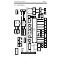
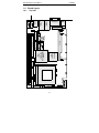
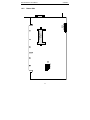
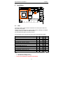
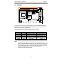
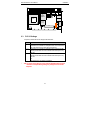
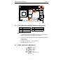
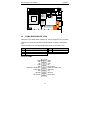
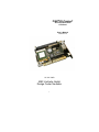
PISA-PIII-TwisterT All-In-One Socket370 CPU Card User's Manual Version 0.3 10 / 06 / 2003 MSC Vertriebs GmbH Design Center Neufahrn 1 Copyright Notice This document is copyrighted, 2002, by MSC Vertriebs GmbH. All rights are reserved. MSC Vertriebs GmbH reserves the right to make improvements to the products described in this manual at any time without notice. No part of this manual may be reproduced, copied, translated or transmitted in any form or by any means without the prior written permission of MSC Vertriebs GmbH. Information provided in this manual is intended to be accurate and reliable. However, MSC Vertriebs GmbH assumes no responsibility for its use, nor for any infringements upon the rights of third parties which may result from its use. * Important Information This product is not an end user product. It was developed and manufactured for further processing by trained personnel. EMC Rules This unit has to be installed in a shielded housing. If not installed in a properly shielded enclosure, and used in accordance with the instruction manual, this product may cause radio interference in which case the user may be required to take adequate measures at his or her own expense. Care and handling precautions for Lithium batteries • • • • • • Do not short circuit Do not heat or incinerate Do not charge Do not deform or disassemble Do not apply solder directly Always observe proper polarities * Caution! Danger of explosion if the battery is incorrectly replaced. When battery replacement is necessary use only the exact same battery or a battery recommended by the manufacturer. Pay attention to the local area regulations regarding the proper disposal of used batteries. 2 1 1.1 1.2 1.3 1.4 2 General Information .......................................................................5 Introduction..................................................................................5 Block Diagram .............................................................................6 Specifications...............................................................................7 Board Layout ...............................................................................12 1.4.1 Top Side ..............................................................................12 1.4.2 Bottom Side .........................................................................13 Installation ......................................................................................14 CPU .............................................................................................14 SDRAM........................................................................................15 PCI I/O Voltage............................................................................16 Clear CMOS Data and BIOS Flash Recovery Jumper.................17 COM1, COM3 and COM4 (RS232) .............................................17 COM2 (RS232/422/485, IrDA) .....................................................18 LCD Interfaces.............................................................................19 2.7.1 LCD Connectors ..................................................................20 2.7.2 Digital Display Data Mapping...............................................21 2.8 AUX Power Connector.................................................................22 2.9 Fan Connectors ...........................................................................22 2.10 Onboard Reset Switch.................................................................23 2.11 System Header ............................................................................23 2.12 Onboard Buzzer...........................................................................24 2.13 Onboard Sound ...........................................................................24 2.14 EIDE ............................................................................................25 2.14.1 Primary Channel ..................................................................25 2.14.2 Secondary Channel (optionally), CompactFlash..................26 2.15 Floppy Disk ..................................................................................27 2.16 Parallel Port .................................................................................27 2.17 Internal USB ................................................................................27 2.18 External USB ...............................................................................28 2.19 RJ45 (Ethernet) ...........................................................................28 2.20 CRT .............................................................................................29 2.21 Keyboard / Mouse Mini-DIN Connector .......................................29 2.22 PISA Edge-Connector .................................................................30 2.23 PC/104 Conncetor .......................................................................31 2.24 Watchdog ....................................................................................32 2.25 PCI Interrupt Routing ...................................................................32 2.26 Interrupts, DMA channels, Upper memory...................................33 2.1 2.2 2.3 2.4 2.5 2.6 2.7 3 Trademarks : PISA is a registered trademark of JUMPtec Industrielle Computertechnik AG JUMPtec is the registered trademark of JUMPtec Industrielle Computertechnik AG 4 PISA-PIII-TwisterT User's Manual 1 1.1 Installation General Information Introduction The PISA-PIII-TwisterT is an all-in-one single board computer card for the PISA bus (PISA = PCI + ISA), designed for Intel‘s new generation PentiumTM III and CeleronTM Tualatin CPUs, as well as VIA’s C3 CPUs in Socket370 package. The board uses the VIA ProSavage PN133T chipset (VT8696 TwisterT Northbridge and VT86286B Southbridge) runing at 100 MHz or 133 MHz front side bus. With an LCD/CRT SXVGA controller, up to two 100MBit Ethernet controllers, an EIDE controller, a floppy controller, as well as sound-, LPT-, keyboard and mouse interfaces, four serial communication ports and four USB ports, the PISA-PIII-TwisterT packs all the functions of an industrial computer onto a single card. This makes it an ideal solution for embedded applications. Two 168-pin standard DIMM socket are giving you the flexibility to configure your system up to 1 GByte of 3.3V SDRAM (PC100 and PC133) . The integrated S3 ProSavage4 AGP 4x 2D/3D/Video accelerator with 128-bit graphic engine uses 8, 16 or 32 MByte of system memory. The PISA-PIII-TwisterT board includes one 36-bit DSTN/TFT flat panel and one 2-channel 110 MHz LVDS interface by actually supporting display types with resolutions up to 1400 x 1050 pixels. Up to two Intel 82551ER PCI 10/100BaseTx Ethernet controllers can be equipped which give access to high speed networks through standard RJ45 connectors in the front panel of the board. The PISA-PIII-TwisterT includes a high speed, local bus EIDE controller. This controller supports (through ATA PIO) mode3, mode4 and Ultra DMA-33/66/100 hard disks, enabling data transfer rates up to 100 MByte/sec. Up to two devices, including large hard disks, CD-ROM drives, tape backup drives, or other IDE devices may be connected to the 40pin 2,54mm primary IDE header. Optionally the secondary EIDE port can be accessed by mounting a CompactFlash connector onto the solder side of the board. Onboard features also include four high-speed RS-232 serial ports (one configurable as RS422/485), one IrDA, one bi-directional SPP/EPP/ECP parallel port, one floppy drive controller and four USB 1.1 ports. 128kbit/sec stereo applications are supported by a SoundBlasterPro/Direct Sound AC97 Digital Audio controller. An onboard 5.25” power connector give the possibility to use the PISA-PIII-TwisterT as a standalone system (without a backplane). The implemented PC/104 interface allows you to install additional functions using standard PC/104 modules. Please visit our web site http://www.msc.de (->products ->downloads ->PISA) where you can find drivers, firmware updates and documentation. 5 +12V PISA 6 FDD KBD Mouse RS422 RS485 IrDA TempEXT COM3 VCC12+ COM4 TempCPU RS232 VCC3 COM1 RS232 COM1 LPT LPT USB 2/3 USB[0:2] Tacho RS422 RS485 COM2 VCCIO VIA Southbridge VT82C686B USB 0/1 USB[0:1] UBat HDD EIDE1 EIDE2 SMBus SMB CompactFlash (optional) ATXEtension PIC12C509A Watchdog Serial E2PROM 4Kx1 3V3_SB RS232 IrDA VCC5 System Monitoring Lithium Battery LVDS Channel 2 PS_ON RS232 UART 16C2550 Keyboard Mouse PCI Intel 82551ER LAN Controller RJ45 Magnetics RJ45 Magnetics Intel 82551ER LAN Controller LVDS Channel 1 36Bit Digital CRT PWR_BTN# Flash-BIOS +12V Floppy Speaker +5V ISA +12V CODEC VT1612A DRAM DIMM max. 512 MB PN133T (VIA Twister-T) VT8606 Northbridge S3 Savage4 2D/3D Graphics Accelerator GND + 5V + 12V Inverter Power Display -5V GND PC/104 GND Line-In, Line-Out; CD-In, MIC DRAM DIMM max. 512 MB I/O Voltage Socket 370 (FC-PGA) CRT -12V Tacho +12V Power In Core Voltage FSB GND FAN Power Tacho FAN Power + 5V +3,3V 1.2 +5V PISA Twister-T PISA-PIII-TwisterT User's Manual Installation Block Diagram GND PISA-PIII-TwisterT User's Manual 1.3 Installation Specifications Core: CPU : • • Socket 370 Intel Pentium III with 512KB L2-Cache, up to 1.26 GHz, 133MHz FSB Socket 370 Intel Celeron with 256KB L2-Cache, up to 1.4 GHz, 100MHz FSB • • • VIA C3 Ezra up to 933 MHz, 100/133 MHz FSB VIA C3 Ezra-T up to 1 GHz, 133 MHz FSB VIA C3 Nehemiah up to 1.2 GHz, 133 MHz FSB ChipSet: VIA ProSavage PN133T VT8696 TwisterT North Bridge VT82686B South Bridge On-chip Caches: • • • Memory: • • Intel Celeron, 32 KB L1 cache, 256KB L2 cache Intel Pentium, III 32 KB L1 cache, 512KB L2 cache VIA C3 CPUs, 128KB L1 cache, 64 KB L2 victim cache 2 Standard 168-Pin DIMM sockets max. 1GByte, PC100 or PC133, independent of FSB speed ISA-Bus Interface: • • • VT86286B South Bridge Standard PISA connector Standard PC/104 connector PCI-Bus Interface: Video: • • VT8696 TwisterT North Bridge Standard PISA connector • • • • • • S3 ProSavage4 AGP4x SXVGA Controller (integrated into North Bridge) 8/16/32 MB fame buffer (shared with system memory) CRT-Interface, 15 pin VGA connector integrated into front panel Flat Panel Interface (36-bit TTL and 2 channel 110 MHz LVDS) Panel type selectable via BIOS setup Connector for backlight inverter power supply Realtime Clock: • VT82686B South Bridge 7 PISA-PIII-TwisterT User's Manual • Installation Lithium battery Ethernet: • • • Floppy Disk: • • Serial: Intel 82551ER Ethernet Controller 10/100 MBit Second Intel 82551ER Ethernet Controller 10/100 MBit optional RJ45 standard connectors integrated into front panel 2 drives supported AT / PS2 compatible floppy disk interface • • • 1 x RS232 (COM1) 1 x RS232/RS422/RS485/IrDA, configurable via BIOS setup (COM2) 2 x RS232 (COM3, COM4) • 1x parallel Port (PS/2-compatible /ECP/EPP, configurable via BIOS setup) • • 2 x USB 1.1 integrated into front panel 2 x USB 1.1 on 2 x 5 pin header Parallel: USB: Keyboard, Mouse: • MFII-Keyboard Interface • PS/2-Mouse Interface BIOS: • • 512 KByte Flash ROM 29F004 (TSOP32) with integrated 64KB boot block PhoenixBIOS 4.0 Release 6.1 Flashdisk: • optional : CompactFlash connector on solder side Watchdog: • • • • PIC12C509 PIC Controller Programmable delay from 1 to 255 seconds or minutes Programmable timeout from 1 to 255 seconds or minutes, action : HW-RESET Re-triggerable via ISA I/O-port Sound: • • • SoundBlasterPro Hardware and DirectSound Ready AC’97 Digital Audio Controller VT1612A AC’97 2.2 VSR Codec Line-out, Line-in, CD-in, MIC-in 8 PISA-PIII-TwisterT User's Manual Installation System Monitoring: • 2 fans (CPU, system) • 3 temperatures (CPU, board, external (2pin pin header)) • 5 voltages (CPU core voltage, +2.5V, +3.3V, + 5V, +12V) Power Supply: +5V ±5% +12V ±5% required for additional PC/104 and fans -12V ±5% only required for additional PC/104 cards Supply Current (Windows 2000 +CPUBURN.EXE): +5V 6.6 A Intel Celeron 1.2 GHz / 1.4 GHz, 100 FBS 6.9 A Intel Pentium III 1.26 GHz, 133 MHz FSB 5.0 A VIA C3 EZRA 800 MHz, 133 MHz FSB 5.2 A VIA C3 EZRA-T 1.0 GHz, 133 MHz FSB 5.5 A VIA C3 NEHEMIAH 1.0 GHz / 1.2 GHz, 133 MHz FSB +12V - depends on PC/104 card and / or fans -12V - depends on PC/104 card Environment: Temperature operating non operating 0 .. + 60°C -25 .. + 85°C Humidity (rel.) operating non operating 0 - 95 % 5 - 95 % Dimensions: 185 x 125 mm 9 PISA-PIII-TwisterT User's Manual Installation Connectors Overview Interface CPU PCI-Bus PC/104 (ISA-Bus) Memory EIDE: Connector Type staggered 370-pins, ZIF-socket PISA standard edge connector Standard 64+40-pins connector (female) 2 x DIMM socket, 168-pins Primary IDC header, 40-pins, 2 rows, 2.54mm, Secondary CampactFlash socket, 50-pins (optional) Floppy IDC header, 34-pins, 2 rows, 2.54 mm Parallel Port IDC header, 26-pins, 2 rows, 2.54 mm COM1 IDC header, 10-pins, 2 rows, 2.54 mm COM2 IDC header, 20-pins, 2 rows, 2.54 mm COM3 IDC header, 10-pins, 2 rows, 2.54 mm COM4 IDC header, 10-pins, 2 rows, 2.54 mm CRT Interface (15pol. HDSUB) HDSUB, 15-pins LCD Panel (digital) IDC header, 50-pins, 2 rows, 2mm LCD Panel (LVDS) FFC connector, 40-pins, 1 row (bottom), 0.5 mm Type HIROSE FH12S-40S-0.5SH LCD Inverter Power pin header 6-pins, 1 row, 2.54 mm LAN 1, 2 RJ-45 (CAT5) USB 1, 2 Dual USB connector, type A USB 3, 4 2 x pin header, 5-pins, 1 row, 2.54 mm Sound pin header, 14-pins, 2 rows, 2.54 mm Fan 1, 2 2x pin header, 3-pins, 1 row, 2.54 mm AUX Power 5¼" power connector Keyboard / Mouse (external) PS/2, 6-pins System Connector: pin header, 30-pins,2 rows, 2.54 mm Keyboard / Mouse (intern) pin header, 7-pins, 1 row, 2.54 mm Reset pin header, 2-pins, 1 row, 2.54 mm Power LED pin header, 5-pins, 1 row, 2.54 mm IDE LED pin header, 2-pins, 1 row, 2.54 mm Speaker pin header, 4-pins, 1 row, 2.54 mm SMBus pin header, 4-pins, 1 row, 2.54 mm Temperature sensor pin header, 2-pins, 1 row, 2.54 mm ATX extension pin header, 4-pins, 2 rows, 2.54 mm 10 PISA-PIII-TwisterT User's Manual Installation Jumpers Name JP1 JP2 JP3 JP4 JP5 JP6 JP7 JP8 JP9 JP10 JP11 JP12 LJP1 LJP2 LJP[3..4] Pins 3 2 3 3 2 3 3 3 2 3 2 3 3 3 3 Description Processor AGTL voltage level VT8606 internal AGTL termination resistors enable / disable Processor pin X4 functionality Processor FSB frequency selection Onboard buzzer enable / disable LCD power supply level LCD power mode Clear CMOS BIOS crises recovery RS485 receive/transmit control RS422/RS485 line termination enable / disable PCI I/O voltage level FAN1 voltage level (solder jumper) FAN1 voltage level (solder jumper) For internal use, must be always open 11 Aux. Power Socket 370 Battery A1 12 Southbridge VIA VT82C686B JP4 Buzzer PC/104 COM1 RS232 Floppy LPT Primary IDE JP5 USB3 USB4 JP6 Northbridge with integrated PROSavage4 AGP 4x Graphics VIA VT8606 JP2 JP3 Backlight Sound Ethernet2 RJ45 Ethernet1 RJ45 USB1/2 COM4 RS232 1.4.1 Reset digital LCD COM3 RS232 1.4 DIMM2 DIMM1 PISA-PIII-TwisterT User's Manual Installation Board Layout Top Side CRT-Monitor JP7 System Header JP1 Keyb./Mouse PS/2 COM2 RS232/422/482/IrDA JP12 JP11 JP10 JP9 JP8 Fan1 Fan2 PISA-PIII-TwisterT User's Manual LVDS Connector Bottom Side LJP1 LJP2 LJP4 LJP3 Compact Flash Socket 1.4.2 Installation 13 PISA-PIII-TwisterT User's Manual Installation DIMM1 COM3 RS232 Battery Backlight USB1/2 USB3 USB4 LPT Northbridge with integrated PROSavage4 AGP 4x Graphics JP4 Buzzer CRT-Monitor JP12 JP11 JP10 JP9 JP8 PC/104 PS/2 VIA VT82C686B Southbridge COM2 RS232/422/482/IrDA JP1 Ethernet2 RJ45 A1 Fan2 Fan1 2.1 Ethernet1 RJ45 JP5 COM1 RS232 Socket 370 Aux. Power COM4 RS232 Floppy VIA VT8606 Reset System Header Primary IDE JP2 JP7 Sound JP6 digital LCD JP3 DIMM2 Keyb./Mouse 2 Installation CPU The PISA-PIII-TwisterT supports Socket 370 Intel Pentium III and Celeron (both Tualatin Cores only) as well as VIA C3 CPUs. It is based on the VIA ProSavage PN133T chipset VT8606 (TwisterT) northbridge and VT82686B southbridge operating at 100 MHz or 133 MHz front side bus. The system performance depends on the CPU you choose. The following table shows the supported CPU types and their recommended jumper settings: CPU / internal frequency / L2-cache / core voltage INTEL Celeron / 1000 / 256 / 100 /1.5 INTEL Celeron / 1100 / 256 / 100 /1.5 INTEL Celeron / 1200 / 256 / 100 /1.5 INTEL Celeron / 1400 / 256 / 100 /1.5 INTEL Pentium III / 1133 / 512 / 133 /1.45 INTEL Pentium III / 1200 / 512 / 133 /1.45 INTEL Pentium III / 1266 / 512 / 133 /1.45 VIA C3 Ezra / 800 / 64 / 133 / 1.35 VIA C3 Ezra / 1000 / 64 / 133 / 1.35 VIA C3 Ezra-T / 1000 / 64 / 100 / 1.45 VIA C3 Nehemiah / 1000 / 64 / 133 / 1.40 VIA C3 Nehemiah / 1000 / 64 / 133 / 1.45 JP1 2–3 2–3 2–3 2–3 2–3 2–3 2–3 1–2 1–2 2–3 2–3 2–3 Note: Intel CPUs have 32 Kbyte L1-caches VIA C3 CPUs have 128 Kbyte L1-caches. * Do not run any CPU without an adequate fan and heatsink! 14 JP2 closed closed closed closed closed closed closed open open closed closed closed JP3 2–3 2–3 2–3 2–3 2–3 2–3 2–3 1–2 1–2 2–3 2–3 2–3 JP4 1–2 1–2 1–2 1–2 2–3 2–3 2–3 2–3 2–3 1–2 2–3 2–3 PISA-PIII-TwisterT User's Manual SDRAM DIMM1 COM3 RS232 Battery Backlight USB1/2 USB3 USB4 LPT Northbridge with integrated PROSavage4 AGP 4x Graphics Ethernet1 RJ45 JP5 COM1 RS232 JP4 Buzzer CRT-Monitor JP12 JP11 JP10 JP9 JP8 Fan2 Fan1 PC/104 PS/2 VIA VT82C686B Southbridge A1 COM2 RS232/422/482/IrDA Ethernet2 RJ45 JP1 Socket 370 Aux. Power COM4 RS232 Floppy VIA VT8606 Reset System Header Primary IDE JP2 JP7 Sound JP6 digital LCD JP3 DIMM2 Keyb./Mouse 2.2 Installation The PISA-PIII-TwisterT board has two DIMM sockets for standard 3,3V SDRAM DIMM modules. The advanced memory controller supports 256 Mbit DRAM technology thus supporting up to 512 Mbyte per bank or 1 Gbyte in one DIMM socket. The following table shows the SDRAM organizations which are supported: Organization 4M x 64 8M x 64 16M x 64 32M x 64 64M x 64 128M x 64 Notes: Capacity 32 MByte 64 MByte 128 MByte 256 MByte 512 MByte 1 GByte Module single or double sided single or double sided single or double sided single or double sided single or double sided double sided max. Capacity (2 DIMMs) 64 MByte 128 MByte 256 MByte 512 MByte 1 GByte 2 GByte The DRAM controller supports PC133 and PC100 memory modules. The memory timing is installed automatically by the BIOS according to the SPD information read from the serial E2PROM on the module. SDRAM clock speed is independent of the selected speed of the CPUs front side bus. If PC133 and PC100 memory modules are mixed on the board, the timing parameters of the slower module will be installed. PC66 memory modules are not supported. 15 PISA-PIII-TwisterT User's Manual Installation DIMM1 COM3 RS232 Battery Backlight USB1/2 USB3 USB4 LPT Northbridge with integrated PROSavage4 AGP 4x Graphics JP4 Buzzer CRT-Monitor PS/2 JP12 JP11 JP10 JP9 JP8 PC/104 Keyb./Mouse VIA VT82C686B Southbridge COM2 RS232/422/482/IrDA JP1 Ethernet2 RJ45 A1 Fan2 Fan1 2.3 Ethernet1 RJ45 JP5 COM1 RS232 Socket 370 Aux. Power COM4 RS232 Floppy VIA VT8606 Reset System Header Primary IDE JP2 JP7 Sound JP6 digital LCD JP3 DIMM2 PCI I/O Voltage Jumper JP12 selects the PCI-I/O voltage for the PISA board. JP12 open 1 –2 2-3 * Function Factory default setting. The PISA board is installed in a backplane which connects the VCCIO pin of the PISA slot to the VCCIO pins of the PCI slots. The PISA board is installed in a backplane with 5V PCI slots and the VCCIO pin of the PISA slot is not connected to the VCCIO pin of any PCI slot. The PISA board is installed in a backplane with 3.3V PCI slots and the VCCIO pin of the PISA slot is not connected to the VCCIO pin of any PCI slot. Or the PISA board is used without a backplane. Take care about correct setting of jumper JP12 if the PISA-PIII-TwisterT board is installed in a backplane. Wrong settings may damage the board and the backplane. 16 PISA-PIII-TwisterT User's Manual Installation DIMM1 COM3 RS232 Battery Backlight USB1/2 USB3 USB4 LPT Northbridge with integrated PROSavage4 AGP 4x Graphics JP4 Buzzer CRT-Monitor PS/2 JP12 JP10 JP11 PC/104 JP9 JP8 Aux. Power Keyb./Mouse VIA VT82C686B Southbridge COM2 RS232/422/482/IrDA JP1 Ethernet2 RJ45 A1 Clear CMOS Data and BIOS Flash Recovery Jumper JP8 1–2 2-3 open Note: 2.5 Ethernet1 RJ45 JP5 COM1 RS232 Socket 370 Fan2 Fan1 2.4 COM4 RS232 Floppy VIA VT8606 Reset System Header Primary IDE JP2 JP7 Sound JP6 digital LCD JP3 DIMM2 Clear CMOS Data Normal operation Clear CMOS data No operation JP9 BIOS Flash Recovery open Normal operation closed Flash programming For BIOS flash recovery operation JP9 has to be closed before power-up and the crises recovery disk has to be installed in floppy drive A>. To clear the contents of the CMOS (setup configuration) the following procedure has to be done : 1. Switch off power. 2. Install jumper at position 2 – 3 for a few seconds. 3. Install jumper again at position 1 – 2. COM1, COM3 and COM4 (RS232) DCD# RXD TXD DTR# GND DSR# RTS# CTS# RI# Not connected 17 PISA-PIII-TwisterT User's Manual Installation DIMM1 COM3 RS232 Battery Backlight USB1/2 USB3 USB4 LPT Northbridge with integrated PROSavage4 AGP 4x Graphics JP4 Buzzer CRT-Monitor PS/2 JP12 JP11 JP10 JP9 JP8 PC/104 Keyb./Mouse VIA VT82C686B Southbridge COM2 RS232/422/482/IrDA JP1 Ethernet2 RJ45 A1 Fan2 Fan1 2.6 Ethernet1 RJ45 JP5 COM1 RS232 Socket 370 Aux. Power COM4 RS232 Floppy VIA VT8606 Reset System Header Primary IDE JP2 JP7 Sound JP6 digital LCD JP3 DIMM2 COM2 (RS232/422/485, IrDA) COM2 can be used in RS232, RS422 or RS485 mode. The basic configuration is done via SETUP. If RS485 mode is selected the signal DTR controls the transmitter, the polarity is determined by JP10. In RS422 or RS485 mode a 100Ω differential termination resistor may be enabled by JP11. JP10 Function 1 – 2 DTR low = transmit, DTR high = receive 2 – 3 DTR high = transmit, DTR low = receive open No function; do not leave open. JP11 Function open Termination resistor disabled closed Termination resistor enabled Connector COM2 DCD# RXD TXD DTR# GND RS422 TXD+ / RS485 Data+ RS422 RXD+ GND IrDA IRRX Not connected DSR# RTS# CTS# RI# Not connected RS422 TXD- / RS485 DataRS422 RXD+ 5V IrDA IRTX Not connected 18 PISA-PIII-TwisterT User's Manual Installation DIMM1 COM3 RS232 LVDS Battery Backlight USB1/2 USB3 USB4 LPT Northbridge with integrated PROSavage4 AGP 4x Graphics JP4 Buzzer CRT-Monitor PS/2 JP12 JP11 JP10 JP9 JP8 PC/104 Keyb./Mouse VIA VT82C686B Southbridge COM2 RS232/422/482/IrDA JP1 Ethernet2 RJ45 A1 Fan2 Fan1 2.7 Ethernet1 RJ45 JP5 COM1 RS232 Socket 370 Aux. Power COM4 RS232 Floppy VIA VT8606 Reset System Header Primary IDE JP2 JP7 Sound JP6 digital LCD JP3 DIMM2 LCD Interfaces The LCD panel type (technology, resolution) can be selected via SETUP. JP6 selects the voltage level for panel power supply on both the 50-pin IDC header for digital flat panels and on the 40-pin FFC connector for LVDS panels. You have to set this jumper according to the type of LCD panel you want to use. JP7 selects if the display power on the connectors should be permanently on, or switched on an off by the panel power sequencing signal ENVDD. Jumpers JP6 1–2 2–3 open LCD Power Level + 3.3 Volt + 5 Volt Open circuit JP7 1–2 2–3 open Backlight Power (header, 6 pins, 2.54 mm) + 12V + 5V GND GND + 5V + 12V 19 LCD Power Mode always on switched with ENVDD No operation, don’t use PISA-PIII-TwisterT User's Manual 2.7.1 Installation LCD Connectors Digital (IDC header, 50 pins, 2.0 mm) +12V GND +5V / +3V ENVEE P0 P2 P4 P6 P8 P10 P12 P14 P16 P18 P20 P22 P24 SHFTCLK M (DE) GND P26 P28 P30 P32 P34 Note: 1 3 5 7 9 11 13 15 17 19 21 23 25 27 29 31 33 35 37 39 41 43 45 47 49 2 4 6 8 10 12 14 16 18 20 22 24 26 28 30 32 34 36 38 40 42 44 46 48 50 LVDS (FCC connector, 40 pins, 0.5 mm) +12V GND +5V / +3V GND P1 P3 P5 P7 P9 P11 P13 P15 P17 P19 P21 P23 P25 FLM (VSYNC) LP (HSYNC) ENBLIGHT P27 P29 P31 P33 P35 N.C. CH1_RED+ CH1_RED ENVEE CH1_GRN+ CH1_GRN N.C. CH1_BLUE+ CH1_BLUE GND CH1_CLK+ CH1_CLK GND N.C. N.C. PDC_DATA CH2_RED+ CH2_RED PDC_CLK CH2_GRN+ CH2_GRN DETECT# CH2_BLUE+ CH2_BLUE GND CH2_CLK+ CH2_CLK GND N.C. N.C. +5V / +3V +5V / +3V +5V / +3V +5V / +3V ENBLIGHT# GND GND +12V +12V +12V 1 2 3 4 5 6 7 8 9 10 11 12 13 14 15 16 17 18 19 20 21 22 23 24 25 26 27 28 29 30 31 32 33 34 35 36 37 38 39 40 The FCC connector for LVDS uses bottom contacts. Turn flat foil cable contact side top down for insertion. 20 PISA-PIII-TwisterT User's Manual 2.7.2 Signal P0 P1 P2 P3 P4 P5 P6 P7 P8 P9 P10 P11 P12 P13 P14 P15 P16 P17 P18 P19 P20 P21 P22 P23 P24 P25 P26 P27 P28 P29 P30 P31 P32 P33 P34 P35 Installation Digital Display Data Mapping Pin# 9 10 11 12 13 14 15 16 17 18 19 20 21 22 23 24 25 26 27 28 29 30 31 32 33 34 41 42 43 44 45 46 47 48 49 50 DSTN16 — — LB1 LB0 — — UB1 UB0 — LG2 LG1 LG0 — UG2 UG1 UG0 — LR2 LR1 LR0 UR2 UR1 UR0 — — — — — — — — — — — — DSTN24 LB3 LB2 LB1 LB0 UB3 UB2 UB1 UB0 LG3 LG2 LG1 LG0 UG3 UG2 UG1 UG0 LR3 LR2 LR1 LR0 UR3 UR2 UR1 UR0 — — — — — — — — — — — — 21 TFT18 — — B0 B1 B2 B3 B4 B5 — — G0 G1 G2 G3 G4 G5 — — R0 R1 R2 R3 R4 R5 — — — — — — — — — — — — TFT24 B0 B1 B2 B3 B4 B5 B6 B7 G0 G1 G2 G3 G4 G5 G6 G7 R0 R1 R2 R3 R4 R5 R6 R7 — — — — — — — — — — — — TFT2x18 R00 R10 R01 R11 R02 R12 R03 R13 R14 R14 R05 R15 G00 G10 G01 G11 G02 G12 G03 G13 G04 G14 G05 G15 B00 B10 B01 B11 B02 B12 B03 B13 B04 B14 B05 B15 PISA-PIII-TwisterT User's Manual Installation DIMM1 COM3 RS232 USB1/2 USB3 USB4 LPT Northbridge with integrated PROSavage4 AGP 4x Graphics Ethernet1 RJ45 JP5 COM1 RS232 JP4 Buzzer CRT-Monitor PS/2 JP12 JP10 JP11 PC/104 JP9 JP8 Aux. Power Keyb./Mouse VIA VT82C686B Southbridge A1 COM2 RS232/422/482/IrDA Ethernet2 RJ45 JP1 Socket 370 Fan2 Fan1 2.8 COM4 RS232 Floppy VIA VT8606 Reset System Header Primary IDE JP2 Battery Backlight JP7 Sound JP6 digital LCD JP3 DIMM2 AUX Power Connector The PISA-PIII-TwisterT board has a 4-pin power connector like standard hard disks have. This connector may be used to power the board if it is used as a stand-alone system without additional ISA- or PCI-cards on a backplane. + 12V GND GND + 5V Note: Square marked pin on solder side is pin # 4 (+5V) , not pin #1 (+12V). 2.9 Fan Connectors Two Fans may be connected to the board. TACHO FAN Power GND Fan power can be selected by solder jumpers LJP1 and LJP2 on the solder side of the PISA-PIIITwisterT board. +12 V FAN power (factory default) Power select FAN1 Power select FAN2 +5 V FAN power 22 PISA-PIII-TwisterT User's Manual Installation DIMM1 COM3 RS232 Battery Backlight USB1/2 USB3 USB4 LPT Northbridge with integrated PROSavage4 AGP 4x Graphics Ethernet1 RJ45 JP5 COM1 RS232 JP4 Buzzer CRT-Monitor PS/2 JP12 JP10 JP11 PC/104 JP9 JP8 Aux. Power Keyb./Mouse VIA VT82C686B Southbridge A1 COM2 RS232/422/482/IrDA Ethernet2 RJ45 JP1 Socket 370 Fan2 Fan1 COM4 RS232 Floppy VIA VT8606 Reset System Header Primary IDE JP2 JP7 Sound JP6 digital LCD JP3 DIMM2 2.10 Onboard Reset Switch The PISA-PIII-TwisterT board has an onboard switch to reset the system. 2.11 System Header PWR_LED + n.c. PWR_LED n.c. GND +5V I2C CLK I2C DAT GND HD_LED + HD_LED EXT_RESET EXT_TEMP(2) + 5V_SB (ATX) (2) GND 1 3 5 7 9 11 13 15 17 19 21 23 25 27 29 2 4 6 8 10 12 14 16 18 20 22 24 26 28 30 KEYB_CLK KEYB_DAT n.c. GND + 5V MOUSE_CLK MOUSE_DAT + 5V n.c. n.c. SPEAKER GND EXT_RESET GND EXT_TEMP PWRBTN# (ATX) (2) PS_ON (ATX) (2) Notes: (1) For temperature sensing connect a 10k NTC to EXT_TEMP and GND EXT_TEMP Reference: SEMITEC JT-Thermistor Type 103JT-025, B=3435K. (2) In order to use ATX extension of the PISA-PIII-TwisterT board connect the appropriate signals of an ATX power supply to these pins. 23 PISA-PIII-TwisterT User's Manual Installation DIMM1 COM3 RS232 Battery Backlight USB1/2 USB3 USB4 LPT Ethernet1 RJ45 JP5 COM1 RS232 Northbridge with integrated PROSavage4 AGP 4x Graphics JP4 Buzzer 2.12 Onboard Buzzer The onboard buzzer can be enabled by jumper JP5. Buzzer enabled dsiabled 2.13 Onboard Sound LINE IN LEFT AGND AGND LINE IN RIGHT MIC IN AGND MIC VCC * 1 3 5 7 9 11 13 2 4 6 8 10 12 14 CD IN LEFT CD GND CD GND CD IN RIGHT SOUND LEFT AGND SOUND RIGHT SOUND LEFT and SOUND RIGHT have no additional amplifiers. Do only connect active speakers to these outputs. 24 CRT-Monitor PS/2 JP12 JP10 JP11 PC/104 JP9 JP8 Fan2 Fan1 Aux. Power Keyb./Mouse VIA VT82C686B Southbridge A1 COM2 RS232/422/482/IrDA Ethernet2 RJ45 JP1 Socket 370 JP5 closed open COM4 RS232 Floppy VIA VT8606 Reset System Header Primary IDE JP2 JP7 Sound JP6 digital LCD JP3 DIMM2 PISA-PIII-TwisterT User's Manual Installation DIMM1 COM3 RS232 USB1/2 USB3 USB4 LPT Northbridge with integrated PROSavage4 AGP 4x Graphics Ethernet1 RJ45 JP5 COM1 RS232 JP4 Buzzer CRT-Monitor PS/2 JP12 JP10 JP11 PC/104 JP9 JP8 Aux. Power Keyb./Mouse VIA VT82C686B Southbridge A1 COM2 RS232/422/482/IrDA Ethernet2 RJ45 JP1 Socket 370 Fan2 Fan1 COM4 RS232 Floppy VIA VT8606 Reset System Header Primary IDE JP2 Battery Backlight JP7 Sound JP6 digital LCD JP3 DIMM2 2.14 EIDE 2.14.1 Primary Channel RESET# DATA7 DATA6 DATA5 DATA4 DATA3 DATA2 DATA1 DATA0 GND DRQ0 IOW# IOR# IORDY DAK0# IRQ14 ADR1 ADR0 CS0# ACTIV# 1 3 5 7 9 11 13 15 17 19 21 23 25 27 29 31 33 35 37 39 2 4 6 8 10 12 14 16 18 20 22 24 26 28 30 32 34 36 38 40 25 GND DATA DATA9 DATA10 DATA11 DATA12 DATA13 DATA14 DATA15 KEY (missing pin) GND GND GND CSEL# GND n.c. CBLID# ADR2 CS1# GND PISA-PIII-TwisterT User's Manual Installation LVDS LCD Connector LJP2 LJP1 LJP3 LJP4 Compact Flash Socket 2.14.2 Secondary Channel (optionally), CompactFlash Pin 1 2 3 4 5 6 7 8 9 10 Name GND DATA3 DATA4 DATA5 DATA6 DATA7 CS1# GND GND GND Pin 11 12 13 14 15 16 17 18 19 20 Name GND GND +5V GND GND GND GND A2 A1 A0 Pin 21 22 23 24 25 26 27 28 29 30 Name Pin Name Pin Name DATA0 31 DATA15 41 RESET# DATA1 32 CS3# 42 IORDY DATA2 33 GND 43 n.c. n.c. 34 IOR# 44 +5V n.c. 35 IOW# 45 ACTIVE# n.c. 36 n.c. 46 n.c. DATA11 37 IRQ15 47 DATA8 DATA12 38 +5V 48 DATA9 DATA13 39 Pulldown 49 DATA10 DATA14 40 n.c. 50 GND Optionally a CompactFlash socket can be mounted onto the solder side of the PISA-PIIITwisterT board. Note: CompactFlash cards are IDE compatible and therefore no special Flash driver or a Flash file system is needed. Capacities for CompactFlash range from 8 Mbyte to 2 Gbyte. The CompactFlash socket is routed to the IDE secondary channel. 26 PISA-PIII-TwisterT User's Manual Installation DIMM1 COM3 RS232 Battery Backlight USB1/2 USB3 USB4 LPT JP4 Buzzer CRT-Monitor PS/2 JP12 JP10 2 4 6 8 10 12 14 16 18 20 22 24 26 28 30 32 34 JP11 PC/104 JP9 JP8 Aux. Power Keyb./Mouse VIA VT82C686B Southbridge A1 COM2 RS232/422/482/IrDA Ethernet2 RJ45 JP1 Socket 370 Fan2 Fan1 1 3 5 7 9 11 13 15 17 19 21 23 25 27 29 31 33 Ethernet1 RJ45 JP5 COM1 RS232 Northbridge with integrated PROSavage4 AGP 4x Graphics 2.15 Floppy Disk GND GND GND GND GND GND GND GND GND GND GND GND GND GND GND GND GND COM4 RS232 Floppy VIA VT8606 Reset System Header Primary IDE JP2 JP7 Sound JP6 digital LCD JP3 DIMM2 2.16 Parallel Port DENSEL# n.c. n.c. INDEX# MTR0# DRVSEL1# DRVSEL0# MTR1# DIR# STEP# WDATA# WGATE# TRK0# WPROT# RDATA# HEADSEL DSKCHG# STB# D0 D1 D2 D3 D4 D5 D6 D7 ACK# BUSY# PE SLCT# 2.17 Internal USB +5V DATA2 DATA2+ GND SHIELD 1 3 5 7 9 2 4 6 8 10 27 +5V DATA3 DATA3+ GND SHIELD 1 3 5 7 9 11 13 15 17 19 21 23 25 2 4 6 8 10 12 14 16 18 20 22 24 26 AFD# ERR# INIT# SLIN# GND GND GND GND GND GND GND GND GND PISA-PIII-TwisterT User's Manual Installation DIMM1 COM3 RS232 Battery Backlight USB1/2 USB3 USB4 LPT Northbridge with integrated PROSavage4 AGP 4x Graphics Ethernet1 RJ45 JP5 COM1 RS232 JP4 Buzzer 2.18 External USB +5V DATA0 - DATA0+ GND +5V DATA1 - DATA1+ GND 2.19 RJ45 (Ethernet) Speed LED Link LED EMI Shield RX - RX+ TX - TX+ The second Ethernet controller is available as an option. 28 CRT-Monitor PS/2 JP12 JP10 JP11 PC/104 JP9 JP8 Aux. Power Keyb./Mouse VIA VT82C686B Southbridge A1 COM2 RS232/422/482/IrDA Ethernet2 RJ45 JP1 Socket 370 Fan2 Fan1 COM4 RS232 Floppy VIA VT8606 Reset System Header Primary IDE JP2 JP7 Sound JP6 digital LCD JP3 DIMM2 PISA-PIII-TwisterT User's Manual Installation DIMM1 COM3 RS232 Battery Backlight USB1/2 USB3 USB4 LPT Northbridge with integrated PROSavage4 AGP 4x Graphics Ethernet1 RJ45 JP5 COM1 RS232 JP4 Buzzer CRT-Monitor PS/2 JP12 JP10 JP11 PC/104 JP9 JP8 Aux. Power Keyb./Mouse VIA VT82C686B Southbridge A1 COM2 RS232/422/482/IrDA Ethernet2 RJ45 JP1 Socket 370 Fan2 Fan1 COM4 RS232 Floppy VIA VT8606 Reset System Header Primary IDE JP2 JP7 Sound JP6 digital LCD JP3 DIMM2 2.20 CRT RED GREEN BLUE reserved GND GND RED GND GREEN GND BLUE 1 2 3 4 5 6 7 8 9 10 11 12 13 14 15 DDC VCC GND SYNC reserved DDC SDA HSYNC VSYNC DDC CLK 2.21 Keyboard / Mouse Mini-DIN Connector M_CLK + 5V MDATA Note: KB_CLK GND KB_CLK A standard PS/2-keybord may be connected directly. In order to use a mouse or both keyboard and mouse an Y-adapter is needed. 29 PISA-PIII-TwisterT User's Manual Installation 2.22 PISA Edge-Connector Pin 1 2 3 4 5 6 7 8 9 10 11 12 13 14 15 16 17 18 19 20 21 22 23 24 25 26 27 28 29 30 31 32 33 34 35 36 37 38 39 40 41 42 43 44 45 46 47 48 49 50 51 52 ISA Bus Top Layer IOCHCK# SD7 SD6 SD5 SD4 SD3 SD2 SD1 SD0 IOCHRDY AEN SA19 SA18 SA17 SA16 SA15 SA14 SA13 SA12 SA11 SA10 SA9 SA8 SA7 SA6 SA5 SA4 SA3 SA2 SA1 SA0 SBHE# LA23 LA22 LA21 LA20 LA19 LA18 LA17 MEMR# MEMW# SD8 SD9 SD10 SD11 SD12 SD13 SD14 SD15 ISA Bus Bottom Layer GND RESETDRV +5V IRQ9 -5V DRQ2 -12V 0WS# +12V GND SMEMW# SMEMR# IOWC# IORC# DACK3# DRQ3 DACK1# DRQ1 REFSH# SYSCLK IRQ7 IRQ6 IRQ5 IRQ4 IRQ3 DACK2# TC BALE +5V OSC GND MEMCS16# IOCS16# IRQ10 IRQ11 IRQ12 IRQ15 IRQ14 DACK0# DRQ0 DACK5# DRQ5 DACK6# DRQ6 DACK7# DRQ7 +5V MASTER# GND 30 PCI Bus Top Layer GND GND INTB# INTD# +5V PCI Bus Bottom Layer GND GND INTA# INTC# +5V +5V PCIRST# GNT0# REQ0# GND PCICLK1 GND AD30 REQ2# V I/O PCICLK2 GND GNT1# GND REQ1# AD31 AD29 PCICLK3 GNT2# AD28 AD26 AD24 AD22 AD20 AD18 PWRGDIN PCICLK4 AD27 AD25 CBE3# AD23 AD21 AD19 REQ3# GND AD16 FRAME# CBE2# TRDY# STOP# GNT3# AD17 IRDY# DEVSEL# LOCK# PERR# GND CBE1# PAR GND SERR# AD15 AD14 AD12 GND GND AD13 AD11 AD9 CBE0# AD6 AD4 AD2 M66EN AD10 AD8 AD7 AD5 AD3 AD1 AD0 +5V +5V GND GND V I/O +5V GND GND PISA-PIII-TwisterT User's Manual Installation 2.23 PC/104 Conncetor Pin 0 1 2 3 4 5 6 7 8 9 10 11 12 13 14 15 16 17 18 19 20 21 22 23 24 25 26 27 28 29 30 31 32 A — IOCHCK# SD7 SD6 SD5 SD4 SD3 SD2 SD1 SD0 IOCHRDY AEN SA19 SA18 SA17 SA16 SA15 SA14 SA13 SA12 SA11 SA10 SA9 SA8 SA7 SA6 SA5 SA4 SA3 SA2 SA1 SA0 GND B — GND RESET +5V IRQ9 MEMR# DRQ2 -12V 0WS +12V GND SMEMW# SMEMR# /IOWC# IORC# DACK3# DRQ3 DACK1# DRQ1 REFSH# SYSCLK IRQ7 IRQ6 IRQ5 IRQ4 IRQ3 DACK2# TC BALE +5V OSC MEMW# GND C GND SBHE# LA23 LA22 LA21 LA20 LA19 LA18 LA17 MRDC# MWTC# SD8 SD9 SD10 SD11 SD12 SD13 SD14 SD15 KEY — — — — — — — — — — — — — 31 D GND MEMS16# IOCS16# IRQ10 IRQ11 IRQ12 IRQ15 IRQ14 DACK0# DRQ0 DACK5# DRQ5 DACK6# DRQ6 DACK7# DRQ7 +5 V MASTER# GND GND — — — — — — — — — — — — — PISA-PIII-TwisterT User's Manual Installation 2.24 Watchdog The watchdog can be enabled via SETUP and the user can define if the counter should start during system boot or later by an application software. It has a programmable delay timer which expires once before the watchdog timer begins counting. After the programmable timeout counter has expired a system reset will be generated. If enabled in SETUP, application software can access the watchdog register via the I/O address defined in SETUP using IN- and OUT instructions. ISA Bus Bit 0 Bit 1 Bit 2 Name RUN (Read/Write) TRIGGER (Read/Write) TIMEOUT (Read only) Description 1 = timeout counter is running. Setting this bit resets TIMEOUT (bit2) and initializes all counters. must be toggled within the specified time interval to reload the timeout counter. 0 = no timeout occurred. Default after power-up or after bit0 is set. 1 = timeout has occurred, system was reset. After a timeout the watchdog is stopped until bit0 is set. 2.25 PCI Interrupt Routing The PISA-PIII-TwisterT board was designed due to PISA specification Rev. 1.7 released in 1997 by Jumptec® Industrial Computer AG. For propper BIOS support the following PCI interrupt routing on external backplanes is recommended. This routing mechanism may different from backplanes that were designed in far eastern countries. PCI Slot1 PCI Slot2 PCI Slot3 PCI Slot4 (AD19) (AD20) (AD21) (AD22) INT A INT A INT A INT A INT A INT B INT B INT B INT B INT B INT C INT C INT C INT C INT C INT D INT D INT D INT D INT D PISA INT A INT A INT D INT C INT B PISA INT B INT B INT A INT D INT C PISA INTC INT C INT B INT A INT D PISA Slot Backplane Slot 1 (AD19) Slot 2 (AD20) Slot 3 (AD21) Slot 4 (AD22) 32 PISA INTD INT D INT C INT B INT A PISA-PIII-TwisterT User's Manual Installation 2.26 Interrupts, DMA channels, Upper memory IRQ Function Available Note 0 Timer 0 No 1 Keyboard No 2 Slave 8259 No 3 COM2 No 1 4 COM1 No 1 5 SoundBlaster Emulation No 1 6 Floppy Disk Controller No 1 7 LPT1 No 1 8 Real Time Clock No 9 Yes 10 COM3 No 1 11 COM4 No 1 12 PS/2 Mouse No 1 13 Floating Point Unit No 14 Primary IDE No 1 15 Secondary IDE No 1 (1) If the device is disabled in SETUP, the interrupt is available. PCI Interrupt Function Comment INT A VGA chipset internal device INT B INT C Sound / Ethernet 1 chipset internal / onboard devices INT D USB / Ethernet 2 chipset internal / optional onboard devices PCI Interrupts may be shared with other peripherals. DMA 0 1 2 3 4 5..7 Used for --(ECP, if enabled) Floppy Disk Controller (ECP, if enabled) Cascade - Available Yes (No) No (No) No Yes Upper Memory C0000h...CDFFFh CE000h...DBFFFh DC000h...DFFFFh Used for VGA BIOS USB legacy Available No Yes No E0000h...FFFFFh System BIOS No 33 Comment alternate, available if disabled default, available if disabled Comment 56 kByte VGA BIOS ISA bus or shadow RAM ISA bus or shadow RAM if disabled exact start address is displayed on summary screen