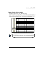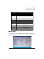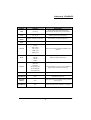
1
VP-MB945G Copyright All rights are reserved. No part of this publication may be reproduced, transmitted, transcribed, stored in a retrieval system or translated into any language or computer language, in any form or by any means, electronic, mechanical, magnetic, optical, chemical, manual or otherwise, without the prior written permission of the company. Brands and product names are trademarks or registered trademarks of their respective companies. The vendor makes no representations or warranties with respect to the contents herein and especially disclaim any implied warranties of merchantability or fitness for any purpose. Further the vendor reserves the right to revise this publication and to make changes to the contents herein without obligation to notify any party beforehand. Duplication of this publication, in part or in whole, is not allowed without first obtaining the vendor’s approval in writing. Trademark All the trademarks or brands in this document are registered by their respective owner. Disclaimer We make no warranty of any kind with regard to the content of this user’s manual. The content is subject to change without notice and we will not be responsible for any mistakes found in this user’s manual. All the brand and product names are trademarks of their respective companies. FCC Compliance Statement This equipment has been tested and found to comply with the limits of a Class B digital device, pursuant to Part 15 of the FCC Rules. These limits are designed to provide reasonable protection against harmful interference in a residential installation. This equipment generates, uses and can radiate radio frequency energy and, if not installed and used in accordance with the instructions, may cause harmful interference to radio communications. Operation of this equipment in a residential area is likely to cause harmful interference in which case the user will be required to correct the interference at his own expense. However, there is no guarantee that interference will not occur in a particular installation. CE Mark The device is in accordance with 89/336 ECC-ENC Directive. Ver: EG101 VP-MB945G Intel® 945G & ICH7 Support Socket 775 Intel® Pentium® Extreme Edition/ Pentium® 4 Extreme Edition/ Pentium® D/ Pentium® 4/Celeron® D Processor User Manual Enabling the Hyper-Threading Technology, your computer system is required to have components as the following: CPU: An Intel® Pentium® 4 Processor with HT Technology Chipset: An Intel® Chipset that supports HT Technology BIOS: A BIOS that supports HT Technology must be enabled OS: An operating system that supports HT Technology For more information on Hyper-Threading Technology, go to: http://www.intel.com/info/hyperthreading Dimensions (ATX form-factor): 230mm x 295mm ( W x L ) Operating System: Windows 2000/ XP Things You Have To Know 0 The images and pictures in this manual are for reference only and may vary from the product you received depending on specific hardware models, third party components and software versions. 0 This mainboard contains very delicate IC chips. Always use a grounded wrist strap when working with the system. 0 Do not touch any IC chip, lead, connector or other components. 0 Always unplug the AC power when you install or remove any device on the mainboard or when confuguring pins and switches. Symbols Attention- Important Information Follow the procedures below… Troubleshooting Tips Refer to other sections in this manual… Table of Contents CHAPTER 1. GETTING STARTED .................................................... 1 INTRODUCTION ....................................................................................................... 1 SPECIFICATION ....................................................................................................... 2 CONFIGURATION .................................................................................................... 5 Layout of VP-MB945G ................................................................................... 5 HARDWARE INSTALLATION ................................................................................... 6 CPU Processor Installation.............................................................................. 6 Memory Installation: DIMM1/2/3/4................................................................ 7 Back Panel Configuration................................................................................ 9 Connectors..................................................................................................... 11 Front Panel Headers: SW/LED, PWRLED, SPEAKER................................ 12 Headers & Jumpers........................................................................................ 14 Audio Configuration...................................................................................... 17 Slots ............................................................................................................... 19 Power Supply Attachments............................................................................ 20 CHAPTER 2. BIOS SETUP ........................................................... 21 INTRODUCTION ..................................................................................................... 21 MAIN MENU ......................................................................................................... 22 ADVANCED BIOS FEATURES ............................................................................... 24 PERIPHERALS ........................................................................................................ 30 POWER MANAGEMENT ......................................................................................... 34 HARDWARE MONITOR.......................................................................................... 37 DEFAULTS ............................................................................................................ 37 EXIT MENU ........................................................................................................... 38 CHAPTER 3: SOFTWARE SETUP................................................... 39 SOFTWARE LIST ................................................................................................... 39 SOFTWARE INSTALLATION ................................................................................... 39 CHAPTER 4: TROUBLESHOOTING................................................. 42 APPENDIX I: SUPER 5.1 CHANNEL AUDIO EFFECT SETUP.................................... 45 APPENDIX II: ABS CARD SETUP .......................................................................... 46 Mainboard VP-MB945G Chapter 1. Getting Started Introduction Thanks for choosing VP-MB945G Mainboard. It is based on Intel® 945G Northbridge chipset and Intel® ICH7 Southbridge chipset. It supports Intel® Pentium® Extreme Edition/ Pentium® 4 Extreme Edition/ Pentium® D/ Pentium® 4/ Celeron® D Processor with FSB (Front Side Bus) frequencies of 1066 MHz/ 800 MHz/ 533 MHz. The VP-MB945G provides two DIMM (Dual In-Line Memory Modules) sockets which allowing you to install 240-pin, unbuffered non-ECC, DDRII 667/ 533/ 400 SDRAMs. It also supports Dual Channel Technology and allows you installing a total memory capacity of 2 GB. This mainboard provides one PCI-E x16 interface slot up to x16 mode, and one PCI-E x1 interface slot up to x1 mode can be supported individually. It is recommended that insert a graphics card onto the PCI-E x16 slot, and insert an expansion card which the interface is capable for PCI-E x1 specification onto the other slot, PCI-E2. In addition, four PCI slots come with this mainboard and are capable for use with expansion cards. The VP-MB945G provides one floppy disk drive connector that can be used with 360KB/720KB/ 1.2MB/1.44MB/2.88MB drives. It also has one IDE connector for IDE hard drives supporting Ultra ATA 66/100. Moreover, the mainboard comes with Serial ATA II feature, four SATA II connectors which the interfaces can provide the transmit rate up to 3 Gbps. The onboard AC’ 97 Audio CODEC (ALC655) supports high quality performance 6-channel audio play (Super 5.1 Channel Audio Effect) <See Appendix I>. The mainboard also supports the Sony/Philips Digital Interfaces (SPDIF) output/input function (Optional). The VP-MB945G also comes with an onboard 10/100 Mbps Ethernet LAN chip. There is a LAN port on the back panel of your case that you can directly plug into an Internet cable. There are maximal eight USB2.0/ 1.1 ports which can be set up on this mainboard. In addition, this mainboard supports the ABS card (Optional), which is a small circuit board inserted onto the mainboard providing full backup BIOS functionality in case of BIOS failure or damage during the BIOS flash <See Appendix II>. All the information (including hardware installation and software installation) in this manual are for reference only. The contents in this manual may be updated without notice. The company will not assume any responsibility for any errors or mistakes within. 1 Mainboard VP-MB945G Specification CPU: Support Socket 775 Support Intel® Pentium® Extreme Edition/ Pentium® 4 Extreme Edition/ Pentium® D/ Pentium® 4/ Celeron® D Processor Support Hyper-Threading Technology Support 1066 MHz/ 800 MHz/ 533 MHz FSB (Front Side Bus) Frequencies Chipset: Northbridge Chipset – Intel® 945G Southbridge Chipset – Intel® ICH7 I/O Controller –ITE® IT8712F AC’ 97 Audio Codec – Realtek® ALC655 LAN Controller – Realtek® RTL 8100C Memory: Two DIMM sockets Supports unbuffered & non-ECC DDRII 667/ 533/ 400 SDRAM Supports a total memory capacity of up to 2 GB Supports Dual Channel data bus Onboard AC’ 97 Sound Codec: High performance Codec with high S/N ratio (>90 db) Compliant with AC’ 97 2.3 specification Supports 6-channel playback capability (Super 5.1 Channel Audio Effect) Supports 3D stereo enhancement Supports Sony/ Philips Digital Interfaces (S/PDIF) functionality (Optional) Slots: Two PCI-Express interface slots for graphics card and expansion card: 1. PCI-E x16 slot: Supports up to x16 mode 2. PCI-E x1 slot: Supports up to x1 mode Four PCI interface slots for expansion cards 2 Mainboard VP-MB945G FDC Connector: Support to set up to two floppy disk drives Support 360KB/ 720KB/ 1.2MB/ 1.44MB/ 2.88MB IDE Connector: One IDE connectors Supports up to two IDE devices Supports Ultra ATA 66/100 Supports high capacity hard disk drives Serial ATA II Connector: Four SATA II connectors Supports SATA 2.0 specification and with transmit rate up to 3 Gb/ s One SATA II connector can only support one SATA II HDD Onboard LAN Chip: 10/100 Mbps Ethernet LAN supported I/O facility Connectors One multi-mode Parallel Port is capable to support as the following: 1. Standard & Bi-direction Parallel Port 2. Enhanced Parallel Port (EPP) 3. Extended Capabilities Port (ECP) Support one serial port Support one VGA ports Support a set of GPIO (GPI, GPO) headers Support one PS/2 mouse port and one PS/2 keyboard port Supports one SPDIF header and one IrDA header compatible with external devices connected Universal Serial Bus: Four onboard USB 2.0/ 1.1 ports Two front USB headers come with this mainboard for additional four USB ports Support a maximum of eight USB ports to connect USB compliant devices 3 Mainboard VP-MB945G BIOS: Phoenix-Award™ BIOS Support APM1.2 Support ACPI 2.0 power management Green Function: Supports Phoenix-Award™ BIOS power management function Supports system-wake-from-power-saving-mode by keyboard or mouse touching Shadow RAM: Integrated memory controller provides shadow RAM functionality and supports ROM BIOS Flash Memory: Supports flash memory functionality Supports ESCD functionality Hardware Monitor Function: Monitors CPU/ Chassis Fan Speed Monitors CPU and system temperature Monitors system voltages Watch Dog Timer: This function is used for detecting the system hangs during the POST stage due to conflicts resulting from changing the system BIOS settings. Once the problem is detected, the system will reset the configurations and reboot the system within five seconds. ABS: Supports ABS card (optional) Supports BIOS backup 4 Mainboard VP-MB945G Configuration Layout of VP-MB945G 5 Mainboard VP-MB945G Hardware Installation This section will assist you in quickly installing your system hardware. Wear a wrist ground strap before handling components. Electrostatic discharge may damage the system’s components. CPU Processor Installation This mainboard supports Intel® Pentium® Extreme Edition/ Pentium® 4 Extreme Edition/ Pentium® D/ Pentium® 4/ Celeron® D Processor using a Socket 775. Before building your system, we suggest you to visit the Intel website and review the processor installation procedures. http://www.intel.com CPU Socket 775 Configuration Steps: Locate the CPU socket 775 on your mainboard and nudge the lever away from the socket as shown. Then lift the lever to a 140-degree angle (A). Next, lift up the iron cover (B). A B C D E F There are 2 distinctive marks located near the corners of the socket on the same side as the lever as shown (C). Match these marks with the marks on the CPU and carefully lower the CPU down onto the socket (D). Replace the iron cover and then lower the lever until it snaps back into position (E). This will lock down the CPU (F). Smear thermal grease on the top of the CPU. Lower the CPU fan onto the CPU/CPU socket and secure it using the attachments or screws provided on the fan. Finally, attach the fan power cord to the CPUFAN header. Attention DO NOT touch the CPU pins in case they are damaged. Also, make sure that you have completed all installation steps before powered on the system. Finally, double-check that the cooling fan is properly installed and the CPU fan power cord is securely attached, in case your CPU and other sensitive components are damaged because of high temperatures. 6 Mainboard VP-MB945G FAN Headers: CPUFAN, AUXFAN, CHASFAN, FAN4 There are four fan headers available for cooling fans. The cooling fans play an important role in maintaining ambient temperatures in your system. The CPUFAN header is attached with a CPU cooling fan. The CHASFAN, AUXFAN, and FAN4 headers are attached with other cooling fans. 1 CPUFAN Pin 1 2 3 4 Assignment Ground +12V FAN RPM rate sense Control Pin 1 AUXFAN/ CHASFAN/ FAN4 1 2 Assignment Ground Power (+12V) FAN RPM rate sense 3 Attention You can avoid damaging your CPU due to high temperatures with proper cooling equipment. It is recommended that attach a cooling fan on top of your CPU. Use the CPUFAN header to attach the fan cord. On most fan power cord, the black wire of the fan cable is the “ground” and should be attached to pin-1 of the header. Memory Installation: DIMM1/2/3/4 The VP-MB945G provides two DIMM (Dual In-Line Memory Modules) sockets which allowing you to install 240-pin, unbuffered non-ECC, DDRII 667/ 533/ 400 SDRAMs. It also supports Dual Channel Technology and allows you installing a total memory capacity of 2 GB. Attention It is recommended that to install memories which are identical specifications (same timing specifications and same DDR II speed) to achieve the best effects. It may cause the failure of power-on or lower memory speed if installing different type, SPD (series presence detects) memories. 7 Mainboard VP-MB945G How to enable Dual-Channel DDRII: 1. 2. 3. 4. This mainboard provides Dual-Channel functionality for the two DIMM sockets. Enabling Dual-Channel can significantly increase your data access rates. DIMM1 and DIMM2 share one channel. For enabling Dual-Channel, you have to install two memories in the DIMM sockets at the same time; according to the definition by Intel, once one channel of the memory capacity is the same with the other channel, then Dual-Channel will be enabled. For example, if you install one 256 MB memory in DIMM1 and the other one in DIMM2 (256MB x 2 = 512MB), so that the Dual-Channel can be enabled. If you only need to install one memory, then the Dual-Channel won’t be enabled. Memory Installation Steps: 1. Pull the white plastic tabs at both ends of the slot away from the slot. 2. Match the notch on the RAM module with the corresponding pattern in the DIMM slot. This will ensure that the module will be inserted with the proper orientation. 3. Lower the RAM module into the DIMM Slot and press firmly using both thumbs until the module snaps into place. 4. Repeat steps 1, 2 & 3 for the remaining RAM modules. * The pictures above are for reference only. Your actual installation may vary slightly from the pictures. 8 Mainboard VP-MB945G Back Panel Configuration PS/2 Mouse & PS/2 Keyboard Ports: KB/MS This mainboard provides a standard PS/2 mouse port and a PS/2 keyboard port. The pin assignments are described below. PS/2 Mouse PS/2 Keyboard Pin Assignment Pin Assignment 1 Data 4 +5 V (fused) 2 No connect 5 Clock 3 Ground 6 No connect Serial and Parallel Interface Ports The mainboard provides one serial port and one parallel port on the back panel. Parallel Interface Port: PRT The parallel port on your mainboard is a standard 25-pin one, and is used to connect a parallel printer. The Serial Interface: COM This mainboard provides a serial port COM on your back panel, and is used to connect mice, modem and other peripheral devices. Through this port, you can also transfer data from your computer hard disk drive to other computers. 9 Mainboard VP-MB945G D-SUB Connector: VGA Your VGA monitor can attach directly to this VGA connector. USB Ports/LAN Port: USB, USB/LAN There are four onboard USB 2.0/ 1.1 ports on the back panel. These USB ports are used to attach with USB devices, such as keyboard, mice and other USB supported devices. There is also a 10/100 Mbps Ethernet LAN port available for you to attach an Internet cable. Pin Assignment Pin Assignment 1 TX+ (TX+) 5 NC (TRD2-) 2 TX- (TX-) 6 RX- (RX-) 3 RX+ (RX+) 7 NC (TRD3+) 4 NC (TRD2+) 8 NC (TRD3-) Pin Assignment Pin Assignment 1/5 +5 V (fused) 3/7 USBP0+/P1+ 2/6 USBP0-/P1- 4/8 Ground Audio Ports: Sound This mainboard provides three audio ports, the Mic-in, Line-in and Line-out. These are the standard audio ports that provide basic audio function. Line-In (Blue) This port is for audio input and connects to external audio devices such as CD player, tape player, etc. When the multi-channel audio system is enabled, this port will output audio for the rear speakers. Line-Out (Green) This port is an output audio port used for connecting to speakers or a headset. When the multi-channel audio system is enabled, this port will output audio for the front speakers. Mic-In (Pink) This port is for connecting to a microphone. When the multi-channel audio system is enabled, this port will output audio for your subwoofer/center speakers. . . This mainboard supports Super 5.1 Channel Audio Effect, and you can transfer 2-channel to 6-channel audio by using a SPDIF Card (Optional) to enable 6 speaker audio. See Appendix I for more information. 10 Mainboard VP-MB945G Connectors Floppy Disk Drive Connector: FDC The mainboard provides a standard floppy disk drive connector (FDC) that supports 360KB/720KB/ 1.2MB/1.44MB/2.88 MB floppy disk drives using a FDD ribbon cable. Primary IDE Connector: IDE1 The mainboard provides one IDE connector that supports Ultra ATA 66/100 IDE devices. You can attach a maximum of two IDE devices, such as hard disk drive (HDD), CD-ROM, DVD-ROM, etc. using an IDE ribbon cable. In general, two IDE devices can be attached onto one IDE connector. If you attach two IDE HDDs, you must configure one drive as the master and the other one as the slave. In this case, one optical device i.e., CD-ROM, DVD-ROM…etc. should be attached to this connector as well. Serial ATA II Connector: SATA1/2/3/4 The four SATA II connectors support 3 Gbps transmit rate, and one SATA connector only can attach one SATA HDD of each time using SATA cables. Furthermore, you will find them in BIOS that SATA 1/3 are showed SATA Channel 0 Master/Slave, and that SATA 2/4 are showed SATA Channel 1 Master/Slave. Please see the picture in the next page above. Pin 1 SATA1~4 Assignment Pin Assignment 1 Ground 2 RSATA_RXN1~4 3 RSATA_RXP1~4 4 Ground 5 RSATA_TXN1~4 6 RSATA_TXP1~4 7 Ground Attention The FDC/ IDE cable is designed and should be attached with a specific direction. One edge of the cable will usually in color such as red, to indicate that should line up with the header pin-1. 11 Mainboard VP-MB945G SATA Channel 0 Master = SATA1 SATA Channel 0 Slave = SATA3 SATA Channel 1 Master = SATA2 SATA Channel 1 Slave = SATA4 Front Panel Headers: SW/LED, PWRLED, SPEAKER Pin Assignment 1 HDD LED (+) 3 HDD LED (-) 5 Reset Control (-) Reset Switch Reset Control (+) (RST_SW) 7 9 SW/LED Pin Assignment Function Hard Drive LED (HD_LED) N/A 2 Power LED (+) 4 Power LED (-) 6 Power Switch (+) 8 Power Switch (-) 10 12 Function Power LED (ACPI_LED) Power-on Switch (PWR_SW) Key Mainboard VP-MB945G Hard Drive LED Header (Red): HD_LED If your case front panel has a hard drive LED cable, attach it to this header. The LED will flicker when there is hard disk drive activity. Reset Switch Header (Blue): RST_SW This header can be attached to a momentary SPST switch (reset button) cable on your case front panel. The switch is normally left open. When the switch closed, it will cause the mainboard to reset and run the POST (Power-On Self Test). Power Switch Header (Orange): PWR_SW This header can be attached to a power switch cable on your case front panel. You can turn your system on or off by pressing the button attached to this power switch cable. 2-pin Power LED Header (Green): ACPI_LED The mainboard provides a 2-pin power LED header. If there is a 2-pin power LED cord on your case front panel, you can attach it to the 2-pin power LED header. Then the power LED will illuminate while the system is powered on. 3-pin Power LED Header (Green): PWR_LED The mainboard also provides a 3-pin power LED header. If there is a 3-pin power LED cord on your case front panel, you can attach it to this 3-pin header instead of attach to the 2-pin one on the SW/LED header. 3-pin PWR_LED Pin Assignment Pin Assignment 1 PWR_LED (+) 2 Key 3 PWR_LED (-) Speaker Header (Purple): SPEAKER A speaker cable on your case front panel can be attached to this header. When you reboot the computer, this speaker will issue a short audible (beep). If there are problems during the Power On Self-Test, the system will issue an irregular pattern of audible beeps through this speaker. SPEAKER Pin 1 3 Assignment PC_BEEP Ground 13 Pin 2 4 Assignment N/C +5V Mainboard VP-MB945G Headers & Jumpers Front USB Headers: USB2/3 This mainboard provides four onboard USB 1.1/2.0 ports (back panel) that attach to USB devices. There are two additional USB headers that can be connected by cables to four more USB ports on the front panel of your case giving you a possible 8 USB ports. USB2/3 Pin 1 3 5 7 9 Assignment +5V (fused) USBUSB+ Ground Key Pin 2 4 6 8 10 Assignment +5V (fused) USBUSB+ Ground Key Attention If you are using a USB 2.0 device with Windows 2000/XP, you will need to install the USB 2.0 driver from the Microsoft® website. If you are using Service pack 1 ® (or later) for Windows XP, and using Service pack4 (or later) for Windows® 2000, you will not have to install the driver. IrDA Header: IrDA The infrared sensing device attached to this header can support to provide wireless infrared. You can transfer data connectionless to or from the portable device (i.e., laptop, PDA, etc.) which with this header attached. Pin IrDA Assignment Pin Assignment 1 N/A 2 Key 3 Ground 4 +5V 5 IR_RX 6 IR_TX GPIO (General Purpose Input/Output) Headers: GPI, GPO This mainboard provides a set of GPIO headers and four GPIO Power headers. GPI is the control of alarm receiving, and GPO is the output control for the warning system. We suggest your attaching the VP-DIO44(Optional)4DI/4DO Control Board for four more VP-DIO44, being able to support up to 16GPI/16GPO. 14 Mainboard VP-MB945G Pin Assignment Pin Assignment 1 GPI 1 2 GPI 2 3 GPI 3 4 GPI 4 5 GPI 5 6 GPI 6 7 GPI 7 8 GPI 8 9 GPI 9 10 GPI 10 11 GPI 11 12 GPI 12 13 GPI 13 14 GPI 14 15 GPI 15 16 GPI 16 Pin Assignment Pin Assignment 1 GPO 1 2 GPO 2 3 GPO 3 4 GPO 4 5 GPO 5 6 GPO 6 7 GPO 7 8 GPO 8 9 GPO 9 10 GPO 10 11 GPO 11 12 GPO 12 13 GPO 13 14 GPO 14 15 GPO 15 16 GPO 16 Power for GPIO Headers: JP6/ JP7/ JP8/ JP9 Pin JP6~9 Assignment 1 12V 3 GND Pin 2 Assignment 5V RS485 Header: JP5 JP5 Pin 1 Assignment Data (+) 15 Pin 2 Assignment Data (-) Mainboard VP-MB945G USB Power Selection Headers: JP4 USB devices attached to USB ports on the back panel of your computer case can awaken the system from sleep mode. In order to enable this functionality, you must adjust the jumper caps on JP4 header for +5V or +5V Standby mode. JP4 1 Pin 1-2 Closed 1 Pin 2-3 Closed Assignment +5V Description S1 sleep mode (CPU stopped, DRAM refreshed, system running in low power mode) S3/S4/S5 sleep modes (no power to CPU, +5V Standby DRAM in slow refresh, power supply in reduced power mode) Note: Close stands for putting a jumper cap onto two header pins. 16 Mainboard VP-MB945G Clear CMOS Jumper: JP1 The “Clear CMOS” function is used when you cannot boot your system due to some CMOS problems, such as a password is forgotten. This jumper allows you to reset the CMOS configurations, and then reconfigure it. JP1 Assignment Normal (Default) Pin 1-2 Close Clear CMOS Data Pin 2-3 Close Note: Close stands for putting a jumper cap onto two header pins. The following steps explain how to reset your CMOS configurations when you have forgotten your system password. 1. Turn off your system and disconnect the AC power cable. 2. Set JP1 header to OFF (2-3 Closed). 3. Wait several seconds. 4. Set JP1 header to ON (1-2 closed). 5. Connect the AC power cable and turn on your system. 6. Reset your new password. Audio Configuration CD-ROM Audio-In Connector: CD-IN The CD-IN connector is used to attach an audio cable to audio devices such as CD-ROMs, DVD-ROMs etc. 1 CD-IN Pin 1 2 3 4 Assignment Left channel input Ground Ground Right channel input SPDIF Header: SPDIF S/PDIF is a recent audio transfer file format, which provides high quality audio using optical fiber and digital signals. This mainboard is capable to deliver audio output and receive audio input through the SPDIF header and FRONT AUDIO header. One way you would use these headers is by using an SPDIF Card (optional) and attaching the cords onto the two specific headers of mainboard. The RCA or TOS-Link 17 Mainboard VP-MB945G connectors will be provided on the SPDIF Card and which are convenient you to output or input audio format files between your system and the SPDIF styled players. SPDIF Pin 1 3 5 Assignment Pin 2 4 +5V SPDIF out SPDIF in Assignment Key Ground Front Audio Header: FRONT AUDIO If your case front panel has audio ports, you can connect them to the Front Audio Header of this mainboard. First, you must remove the jumper caps on this header and then attach the cables from the front panel to the pins on this header. You can use both the front audio panel and back panel audio simultaneously. If you are not using front panel audio ports, leave the jumper caps on the header pins (Note: pins 5-6 and 9-10) to avoid problems with the back panel audio ports. Pin 1 3 5 7 9 Assignment Mic in/center Mic_VREF Front out_R N/A Front out_L FRONT AUDIO Pin Assignment 2 Ground 4 Audio power +5V 6 Rear out_R 8 Key 10 Rear out_L 18 Mainboard VP-MB945G Slots PCI-Express x16 Interface slot: PCI-E1 The PCI-E1 slot is the PCI-Express x16 interface slot which can be supported up to x16 mode. It is recommended that you insert a graphics card onto the PCI-E1 slot which the interface is capable for PCI-E x16 specification. PCI-Express x1 Interface slot: PCI-E2 The PCI-E2 slot is the PCI-Express x1 interface slot which can be supported up to x1 mode. You can insert an expansion card which the interface is capable for PCI-E x1 specification onto the slot, PCI-E2. PCI Interface Slots: PCI1/2/3/4 PCI stands for Peripheral Component Interconnect, which is a bus standard for installing expansion cards such as network card, SCSI card, etc. to these PCI slots. 19 Mainboard VP-MB945G Power Supply Attachments ATX Power Connector: ATX_PWR, ATX_12V This mainboard provides two ATX power connectors, a 24-pin ATX_PWR connector and a 4-pin ATX_12V connector. You must use a power supply that has both of these connectors and both connectors must be attached before the system is powered on. These power connectors support several power management functions such as the instant power-on function. The connector pins are described below. ATX_PWR ATX_12V Pin 1 2 3 4 5 6 7 8 9 10 11 12 Pin Assignment +3.3V +3.3V Ground +5V Ground +5V Ground PW_ON +5V standby voltage +12V +12V +3.3V Assignment Pin 13 14 15 16 17 18 19 20 21 22 23 24 Pin Assignment +3.3V -12V Ground PS_ON Ground Ground Ground -5V +5V +5V +5V Ground Assignment 1 +12V 3 Ground 2 +12V 4 Ground Attention In general, power cords are designed and should be attached with a specific direction. The black wire of the power cord is Ground and should be attached onto the header location of Ground. 20 Mainboard VP-MB945G Chapter 2. BIOS Setup Introduction This section describes PHOENIX-AWARD™ BIOS Setup program which resides in the BIOS firmware. The Setup program allows users to modify the basic system configuration. The configuration information is then saved to CMOS RAM where the data is sustained by battery after power-down. The BIOS provides critical low-level support for standard devices such as disk drives, serial ports and parallel ports. As well, the BIOS controls the first stage of the boot process, loading and executing the operating system. The PHOENIX-AWARDTM BIOS installed in your computer system’s ROM is a custom version of an industry standard BIOS. This means that it supports the BIOS of Intel® based processors. This version of the PHOENIX-AWARDTM BIOS includes additional features such as virus and password protection as well as special configurations for fine-tuning the system chipset. The defaults for the BIOS values contained in this document may vary slightly with the version installed in your system. EPA Green PC Support This PHOENIX-AWARD™ BIOS supports the Version 1.03 of EPA Green PC specification. APM Support This PHOENIX-AWARD™ BIOS supports the Version 1.1 & 1.2 of Advanced Power Management (APM) specification. These features include system sleep and suspend modes in addition to hard disk and monitor sleep modes. Power management features are implemented using the System Management Interrupt (SMI). PCI/ PCI-Express Bus Support This PHOENIX-AWARD™ BIOS also supports Version 2.3 of the Intel PCI (Peripheral Component Interconnect) local bus specification and the PCI-Express v1.0a specification. DRAM Support DDR2 SDRAM (Synchronous DRAM) is supported. Supported CPUs This PHOENIX-AWARD™ BIOS supports the Intel® Pentium® 4 CPUs. Key Function In general, you can use the arrow keys to highlight options, press <Enter> to select, use the <PgUp> and <PgDn> keys to change entries, press <F1> for help and press <Esc> to quit. The following table provides more detail about how to navigate within the BIOS Setup program. 21 Mainboard VP-MB945G Keystroke Function Up arrow Move to previous option Down arrow Move to next option Left arrow Move to the option on the left (menu bar) Right arrow Move to the option on the right (menu bar) Esc Main Menu: Quit without saving changes Submenus: Exit Current page to the next higher level menu Move Enter Move to the option you desire PgUp key Increase the numeric value or enter changes PgDn key Decrease the numeric value or enter changes + Key Increase the numeric value or enter changes - Key Decrease the numeric value or enter changes Esc key Main Menu – Quit and do not save changes into CMOS Status Page Setup Menu and Option Page Setup Menu – Exit Current page and return to Main Menu F1 key General help on Setup navigation keys F5 key Load previous values from CMOS F6 key Load the defaults from BIOS default table F7 key Load the turbo defaults F10 key Save all the CMOS changes and exit Main Menu When you enter the PHOENIX-AWARD™ BIOS Utility, the Main Menu will appear on the screen. The Main menu allows you to select from several configuration options. Use the left/right arrow keys to select a particular configuration screen from the top menu bar or use the down arrow key to access and configure the information below. 22 Mainboard VP-MB945G Option Options Description Date mm dd yy Set the system date. Note that the ‘Day’ automatically changes when you set the date. Time hh: mm: ss Set the current time of the system. Options contained in sub menu. Press <Enter> to enter the sub menu. Options contained in sub menu. Press <Enter> to enter the sub menu. IDE Channel 0 Master IDE Channel 0 Slave None; 360k, 5.25 in; Driver A 1.2M, 5.25 in; 1.44M, 3.5 in; Select the type of floppy disk drive installed in your system. 2.88M, 3.5 in EGA/VGA; Video CGA 40; Select the default video device. CGA 80; MONO All Errors; No Errors; Halt On All, but Keyboard; All, but Diskette; Select the situation in which you want the BIOS to stop the POST process and notify you. All, but Disk/ Key Security Options contained in sub menu. Press <Enter> to enter the sub menu. Base Memory N/A Displays the amount of conventional memory detected during boot up. Extended Memory N/A Displays the amount of extended memory detected during boot up. Total Memory N/A Displays the total memory available in the system. 23 Mainboard VP-MB945G Advanced BIOS Features Hard Disk Boot Priority Select hard disk boot priority. CD-ROM Boot Priority Select hard CD-ROM boot priority when you plug a CD-ROM drive onto your system. First /Second/Third Boot Device Select the order in which devices will be searched in order to find a boot device. Options: Hard Disk (Default for first boot device), CDROM (Default for second boot device), Removable (Default for third boot device), Disabled Boot Other Device The setting allows the system to try to boot from other devices if the system fails to boot from the 1st/ 2nd/ 3rd boot devices. Options: Enabled (Default), Disabled Boot Up Floppy Seek When Enabled, the BIOS tests (seeks) floppy drivers to determine whether they have 40 or 80 tracks. Only 360 KB floppy drivers have 40 tracks. Drives with 720 KB, 1.2 MB and 1.44 MB capacity have 80 tracks. Because very few modern PCs have 40-tracks floppy drivers, we recommend that you set this option to “Disabled”. Options: Enabled, Disabled (Default) Advanced BIOS Features 24 Mainboard VP-MB945G CPU Feature Delay Prior to Thermal Select the delay time before thermal activation from high temperatures. Options: 4 Min, 8 Min, 16 Min (Default), 32 Min Thermal Management This option will monitor the CPU thermal to prevent the CPU damage with high temperature. Limit CPUID MaxVal When the limit CPUID MaxVal is set to 3, the option should be set to “Disabled” for Windows XP. Options: Enabled, Disabled (Default) C1E Function This item allows you to select C1E Function. Options: Auto (Default), Disabled Execute Disable Bit When disabled, forces the XD feature flag to always return 0. Options: Enabled (Default), Disabled Virus Warning This option allows you to choose the Virus Warning feature for IDE Hard Disk boot sector protection. If this function is enabled and someone attempts to write data into this area, BIOS will display a warning message on the screen and sound an audio alarm (beep). Options: Disabled (Default), Enabled CPU L1 & L2 Cache Make CPU internal cache active or inactive. System performance may degrade if you disable this option. Options: Enabled (Default), Disabled. Hyper-Threading Technology When you install a CPU include Hyper-Threading Technology. And this option will allow you to enable or disabled the Hyper-Threading technology. Options: Disabled, Enabled (Default) Quick Power On Self Test Allow the system to skip certain tests while booting. This will speed up the boot process. Options: Enabled (Default), Disabled. Boot Up NumLock Status Select the power on state for NumLock. Options: On (Default) Numpad keys are number keys. Off Numpad keys are arrow keys. Typematic Rate Setting When the options of “Enabled”, “typematic rate,” and “typematic delay” can be configured, the Typematic Rate determines the keystroke repeat rate used by the keyboard controller. 25 Mainboard VP-MB945G Options: Disabled (Default), Enabled Typematic Rate (Chars/Sec) The rate of a character repeated needs. Options: 6 (Default), 8, 10, 12, 15, 20, 24, 30 Typematic Delay (Msec) The delay values before keystrokes begin to repeat. Options: 250 (Default), 500, 750, 1000. APIC Mode “MPS version control for OS” must be configured if this function wants to be enabled. Options: Disabled, Enabled (Default) MPS Version Control For OS The 1.1 version is the older version that supports 8 more IRQs in the Windows NT environment. Choose the new 1.4 version for Windows 2000 and Windows XP. Options: 1.4 (Default), 1.1 OS Select For DRAM > 64MB Select “OS2” only if you are running the OS/2 operating system with greater than 64MB of RAM. Options: Non-OS2 (Default), OS2 HDD S.M.A.R.T. Capability The Self Monitoring Analysis and Reporting Technology is a technology that enables a PC to attempt to predict the possible failure of storage drives. Options: Disabled, Enabled (Default) Intel OSB Logo Show This option allows you to show or hide the small LOGO EPA. Options: Disabled, Enabled (Default) Advanced Chipset Features DRAM Timing Selectable This option determines DRAM clock/ timing using SPD or manual configuration. Make sure your memory module has SPD (Serial Presence Data), if you want to select the “By SPD” option. Options: Manual, By SPD (Default) CAS Latency Time This option determines CAS Latency. When synchronous DRAM is installed, the number of clock cycles of CAS latency depends on the DRAM timing. Do not reset this option from the default value specified by the system engineer. This option is adjustable only when “DRAM Timing Selectable” is set to “Manual”. This option is locked when “DRAM Timing Selectable” is set to “By SPD” and is automatically determined by the system. Options: 5, 4, 3, 6, Auto (Default) 26 Mainboard VP-MB945G DRAM RAS# to CAS# Delay This option allows you to select a delay time between the CAS and RAS strobe signals. It only applies when DRAM is written to, read from, or refreshed. This option is adjustable only when “DRAM Timing Selectable” is set to “manual”. This option is locked when “DRAM Timing Selectable” is set to “By SPD” and is automatically determined by the system. Options: 2, 3, 4, 5, 6, Auto (Default) DRAM RAS# Precharge This option allows you to select the DRAM RAS# precharged time. The ROW address strobe must be precharged again before DRAM is refreshed. An inadequate configuration may result in incomplete data. This option is adjustable only when “DRAM Timing Selectable” is set to “manual”. This option is locked when “DRAM Timing Selectable” is set to “By SPD” and is automatically determined by the system. Options: 2, 3, 4, 5, 6, Auto (Default) Precharge Delay (tRAS) This option allows you to select DRAM Active to Precharge Delay. This option is locked when “DRAM Timing Selectable” is set to “By SPD” and is automatically determined by the system. Options: Auto (Default), 4, 5, 6, 7, 8, 9, 10, 11, 12, 13, 14, 15 System BIOS Cacheable When enabled, accesses to system BIOS ROM addressed at F0000H-FFFFFH are cached, provided that the cache controller is enabled. Options: Enabled (Default), Disabled Video BIOS Cacheable Select “Enabled” to allow caching of the video BIOS which may improve performance. If any other program writes to this memory area, a system error may result. Options: Enabled, Disabled (Default) Memory Hole at 15M-16M When enabled, you can reserve an area of system memory for ISA adapter ROM. When this area is reserved, it cannot be cached. Refer to the user documentation of the peripheral you are installing for more information. Options: Disabled (Default), Enabled PCI Express Root Port Func PCI Express Port 1 This option allows you to enabled or disabled PCI Express x 1 port 1. Options: Auto (Default), Enabled, Disabled PCI-E Compliancy Mode This option allows you select the PCI-E Compliancy Mode. Options: V1.0a (Default), V1.0 ** VGA Setting ** On-Chip Frame Buffer Size This setting is for pure DOS mode using, you can set 1MB or 8MB to share the system memory. 27 Mainboard VP-MB945G Options: 1 MB, 8 MB (Default) DVMT Mode This option allows you to set the DVMT Mode. DVMT is an enhancement of the UMA concept, wherein the graphics driver allocates memory as needed for running graphics applications. The graphics driver is cooperatively using this memory with other system components. If a user is not performing any graphics-intensive operations, most of the DVMT memory can be utilized by the operating system for other uses. In an environment where the user is unlikely to run games that require a large amount of memory, the memory will be available for other uses such as database applications etc. In an environment where the user is playing games or may not run any data intensive non-graphics applications, the memory will automatically be used to optimize the graphics. Intel recommends using the DVMT setting for better overall system performance. Options: FIXED, DVMT (Default), BOTH DVMT/FIXED Memory Size This item will allows you to select the memory size for graphic use. And it is intended to provide the user with a guaranteed amount of graphics memory at all time. However, the OS will still report total system memory as including this allocated amount (as opposed to pre-allocated.) Options: 64MB, 128MB (Default), 224MB Boot Display This option allows you to select boot display. Options: Auto (Default), CRT, TV, EFP PnP/PCI Configurations PCI / VGA Palette Snoop Some graphic controllers that are not VGA compatible take the output from a VGA controller and map it to their display as a way to provide boot information and VGA compatibility. Options: Disabled (Default), Enabled PCI Latency Timer (CLK) This option allows you to set up the PCI Latency Time (0-255). If you select the “32” it will optimize PCI speeds. Options: 0 ~ 255, 32 (Default) PCI SLOT1/2/3/4 This option allows you to select an IRQ address for PCI slot 1/2. Options: Auto (Default), 3, 4, 5, 7, 9, 10, 11, 12, 14, 15 **PCI Express relative Items** Maximum Payload Size This option allows you to set the PCI Express Maximum payload size per time. Options: 128 (Default), 256, 512, 1024, 2048, 4096 Frequency/Voltage Control CPU Host Frequency (MHz) 28 Mainboard VP-MB945G This option displays the CPU Host frequency. You can set it from 266 to 400. The default depends on your CPU frequency. The default for this option depends on the CPU installed. CPU Clock Ratio This option is display only if the CPU has not been set to a locked state by the CPU manufactory. If your CPU is locked, you will not be able to adjust the “CPU Clock Ratio”. The default depends on your CPU. System Memory Frequency This option allows you to select Memory Frequency. Options: Auto (Default), 400 MHz, 533 MHz, 667 MHz CPU Speed Detected This option displays the current CPU speed. CPU Speed Setting This option display the CPU speed that you setting for. If you don’t change the “CPU Host Frequency” or the “CPU Clock Ratio” and the option will display the current CPU speed. PCI Express Selectable This option determines the PCI-E frequency. You can set the frequency using the supplied BIOS options. One of the options available to you is “Auto”. Using the “Auto” option will instruct the system to automatically calculate the frequency. When you select the option “Fixed,” then the following item “Fixed PCIE Freq (MHz)” will be available. Options: Auto (Default), Fixed Fixed PCIE Freq (MHz) This option determines the PCI-E frequency. This field is adjustable only when the “PCI Express Selectable” is set to “Fixed.” Options: 100 ~ 110, 100 (Default) CPU: PCIE: PCI Freq (MHz) This option display the CPU, PCIE, and PCI frequency that you setting for. If you don’t change the “CPU Host Frequency” or the “Fixed PCIE Freq,” the option will display the current CPU frequency. Spread Spectrum The Spread Spectrum function can reduce the EMI (Electromagnetic Interference) generated. Options: Enabled (Default), Disabled 29 Mainboard VP-MB945G Peripherals Init Display First With systems that have multiple video cards, this option determines whether the primary display uses a PCI slot or a PCIE slot. Options: PCI Slot (Default), Onboard, PCIEx OnChip IDE Device IDE HDD Block Mode Block mode is otherwise known as block transfer, multiple commands, or multiple sectors read/ write. Select the “Enabled” option if your IDE hard drive supports block mode (most new drives do). The system will automatically determine the optimal number of blocks to read and write per sector. Options: Enabled (Default), Disabled On-Chip Primary/ Secondary PCI IDE The mainboard chipset contains a PCI IDE interface with support for two IDE channels. These two IDE channels are for IDE1 and SATA1/2/3/4 connectors use. Select “Enabled” to activate the first and/or second IDE interface. Select “Disabled” to deactivate the interface if you are going to install a primary and/or secondary add-in IDE interface. Options: Enabled (Default), Disabled IDE Primary/ Secondary/ Master/ Slave PIO The IDE PIO (Programmed Input / Output) options let you set a PIO mode (0-4) for each of the IDE devices that the onboard IDE interface supports. Modes 0 to 4 will increase performance incrementally. In Auto mode, the system automatically determines the best mode for each device. Options: Auto (Default), Mode0, Mode1, Mode2, Mode3, Mode4. IDE Primary/ Secondary/ Master/ Slave UDMA Ultra DMA 100 functionality can be implemented if it is supported by the IDE hard drives in your system. As well, your operating environment requires a DMA driver (Windows 95 OSR2 or a third party IDE bus 30 Mainboard VP-MB945G master driver). If your hard drive and your system software both support Ultra DMA 100, select “Auto” to enable BIOS support. Options: Auto (Default), Disabled ***OnChip Serial ATA Setting*** On-Chip Serial ATA This field allows you to select the on-chip Serial ATA operating mode which will determine how you will use your Serial ATA drives with the other standard IDE drives. This system can physically attach 2 IDE drives and 4 SATA drives but will have certain limitations as described below. Options: Disabled Auto Combined Mode Enhanced Mode(default) SATA Only Disable on-chip serial ATA. No Serial ATA devices installed. BIOS will auto-detect the presence of any SATA devices. If you install 2 (or 1) IDE drivers + 4 (or 3) SATA drivers Æ Enhanced Mode 2 (or 1) IDE drivers + 2 (or 1) SATA drivers (Must connect with SATA1 +3 or SATA2+4) Æ Combined Mode 4 ( or 3 or 2 or 1)SATA drivers Æ SATA only 2 (or 1) IDE drivers Æ Disabled Windows® 98/ME can recognize IDE devices but cannot directly recognize an SATA device and therefore you must use this mode to allow the SATA device to simulate an IDE device by assuming the role of one IDE channel in the system. This means that you will have one available IDE channel for 2 SATA drives to use (each IDE channel can support 2 IDE drives). If you were to install all both IDE drives and 4 SATA drives, you will only see 2 of the SATA drives along with the 2 IDE drives in this mode. In this mode, you can use all 6 hard disk drives (including 2 IDE drives and 4 SATA drives). Note: You cannot use “Enhanced” mode with Windows® 98/ME. It only support to install Windows® 2000/ XP if you want to boot from SATA device. (It’s restriction from Microsoft.) Select this option when you install SATA drives only. PATA IDE Mode This option allows you to select an IDE channel for PATA IDE devices. When you install the SATA device(s) to the SATA1 or 3 or 1+3, this option should be set to Secondary. When you install the device(s) to the SATA2 or 4 or 2+4, this option should be set to Primary. Options: Primary (Default), Secondary SATA Port This option will display which IDE channel will be used to the SATA device. Options: SATA1, 3 is channel 0; SATA2, 4 is channel 1 (Default) Onboard Device USB Controller This option should be enabled if your system has a USB port installed on the system board. You will need to disable this feature if you add a higher performance controller. 31 Mainboard VP-MB945G Options: Enabled (Default), Disabled USB 2.0 Controller This option should be enabled if your system has a USB 2.0 device installed on the system board. You will need to disable this feature if you install a USB 1.1 device. Options: Enabled (Default), Disabled USB Keyboard Support Enables support for USB attached keyboards. Options: Disabled (Default), Enabled Audio Device This option allows you to control the onboard audio. Options: Auto (Default), Disabled Onboard LAN Controller This option allows you to choose whether enable the LAN on the mainboard or not. Options: Disabled, Enabled (Default) Super I/O Device Power On Function This option allows you to select a way to power on your computer. Options: Password, Hot KEY, Mouse Move, Mouse Click, Any KEY, BUTTON ONLY (Default), Keyboard 98 KB Power On Password This option is as a part of power-on sequences with your system. This option is configurable only when “Power-On Function” is set with “Password”. Hot Key Power ON This option allows you to use the Ctrl key along with a hot key (function key) to power on your system. This option is configurable only when “Power-On Function” is set to “Hot Key”. Options: Ctrl-F1 (Default), Ctrl-F2……Ctrl-F12 Onboard FDC Controller Select “Enabled” if your system has a floppy disk controller (FDC) installed on the system board and you need to use it. If you install an add-in FDC or the system has no floppy drive, select “Disabled”. Options: Enabled (Default), Disabled Onboard Serial Port 1/2 Select an address and corresponding interrupt for the first/ second serial port. Options: Disabled, 3F8/IRQ4 (Default for port1), 2F8/IRQ3 (Default for port2), 3E8/IRQ4, 2E8/IRQ3, Auto UART Mode Select This option allows you to select the Infra Red (IR) standard to be used. Options: Normal (Default), IrDA, ASKIR, SCR 32 Mainboard VP-MB945G UR2 Duplex Mode Select the transmission mode used by the IR interface. Full-duplex mode permits simultaneous bi-directional transmission. Half-duplex mode permits transmission in only one direction at a time. This option is configurable only if “UART Mode Select” is set to “IrDA”. Options: Half (Default), Full Onboard Parallel Port Select an address and corresponding interrupt for the onboard parallel port. Options: 378/IRQ7 (Default), 278/IRQ5, 3BC/IRQ7, Disabled Parallel Port Mode This option allows you Options: SPP (Default) EPP ECP ECP+EPP to select a parallel port mode for the onboard parallel port. Standard Printer Port Enhanced Parallel Port Extended Capabilities Port ECP & EPP mode. ECP Mode Use DMA Select a DMA Channel for the parallel port when using the ECP mode. This option is configurable only if “Parallel Port Mode” is set to “ECP”. Options: 3 (Default), 1 PWRON After PWR-Fail This option will determine whether your system will boot after restoring power after a power failure. If you select “On”, the system will boot whether or not the system was on before power failure. If you select “Former-Sts”, the system will be restored to the status before the power failure. Options: Off, On, Former-Sts (Default) GPIN Status GPI 1~16 VALUE 1 This option will detect the high and low voltages automatically, and then show the General Purpose Input status GPO Status GPO 1~16 Setting This option will determine General Purpose Output control. Options: 0 (Default), 1 33 Mainboard VP-MB945G Power Management The Power Management Setup Menu allows you to configure your system to utilize energy conservation features as well as power-up/ power-down options. ACPI Suspend Type The option allows you to select the suspend type using the ACPI operating system. Options: S1 (POS) (Default) Power on Suspend S3 (STR) Suspend to RAM S1 & S3 POS and STR Run VGABIOS if S3 Resume Select whether you want to run VGABIOS when the system wakes up from the S3 suspend function. This option is not configurable if “ACPI Suspend Type” is set to “S1(POS)”. Options: Auto (Default), Yes, No Power Management There are three options of Power Management: 1. Min. Saving Minimum power management Suspend Mode = 1hour HDD Power Down = 15 minutes 2. Max. Saving Maximum power management (only available for sl CPUs). 34 Mainboard VP-MB945G Suspend Mode = 1 minute HDD Power Down = 1 minute 3. User Defined (Default) This option allows you to set each mode individually. When this option is enabled, each of the ranges is from 1 minute to 1 hour except for HDD Power Down, which ranges from 1 minute to 15 minute and includes a “disable” option. Note: If you select Min. or Max. Power Saving modes, the “HDD Power Down” value and the “Suspend Mode” value are both fixed. Video Off Method This option determines the manner in which the monitor goes blank. Options: Blank Screen (Default) This option only writes blanks to the video buffer. V/H SYNC + Blank This selection will cause the system to turn off the vertical and horizontal synchronization ports and write blanks to the video buffer. DPMS Initial display power management signaling. Video Off In Suspend This determines whether power to the monitor is switched off when the computer is in suspend mode. Options: Yes, No (Default) Suspend Type This option allows you to select the suspend type under the ACPI operating system. Options: Stop Grant (Default), PwrOn Suspend MODEM Use IRQ This determines the modem’s IRQ. Options: 3 (Default), 4, 5, 7, 9, 10, 11, NA Suspend Mode This option allows you to select the suspend time under the ACPI operating system. Options: Disabled (Default), 1Min, 2Min, 4Min, 8Min, 12Min, 20Min, 30Min, 40Min, 1Hour HDD Power Down When enabled, the hard disk drive will power down after a certain configurable period of system inactivity. All other devices remain active. Options: Disabled (Default), 1 Min, 2 Min, 3 Min, 4 Min, 5 Min, 6 Min, 7 Min, 8 Min, 9 Min, 10 Min, 11 Min, 12 Min, 13 Min, 14 Min, 15Min Soft-Off by PWR-BTTN In situations where the system enters a “hung” state, you can configure the BIOS so that you are required to pre the power button for more than 4 seconds before the system enters the Soft-Off state. Options: Delay 4 Sec, Instant-Off (Default). 35 Mainboard VP-MB945G Wake Up Control If you highlight the “Wake Up Control” label and then press the enter key, it will display a submenu with the following options. PCI PME Wake Up This option will also cause the system to wake up with any onboard LAN activity. Options: Disabled (Default), Enabled Ring Wake Up This option allows you to awaken the system upon receiving an incoming call to modem device. Options: Disabled (Default), Enabled. USB KB Wake-up From S3 This option allows you to awaken the system from suspend mode using a USB keyboard. Options: Enabled, Disabled (Default) * This option is configurable only when the ACPI Suspend Type is set to S3. RTC Wake Up When “Enabled”, you can set the date and time at which the RTC (real-time clock) alarm awakens the system from Suspend mode. Options: Enabled, Disabled (Default). Date (of Month) Alarm You can choose which date of the month the system will boot up. This option is configurable only when “RTC Wake Up” is set to “Enabled”. Time (hh: mm: ss) Alarm You can choose the hour, minute and second the system will boot up. This option is configurable only when “RTC Wake Up” is set to “Enabled”. **Reload Global Timer Events** When a system goes into suspend mode, certain devices must be inactive for a period of time. Conversely, if any of those devices have any activity, the system will awaken. You can select the devices that will participate in suspend/power-on activity by configuring these options. Devices include: Primary IDE 0/ Primary IDE 1/ Secondary IDE 0/ Secondary IDE 1/ FDD, COM, LPT Port/ PCI PIRQ [A-D] #. Options: Disabled (Default), Enabled 36 Mainboard VP-MB945G Hardware Monitor Smart FAN Control This item allows you to select the “Smart Fan Control” that monitors the CPU temperature and intelligently adjusts the CPUFAN speed to maintain safe temperature for your CPU. In addition, the Smart Fan Control can reduce noise levels by lowering fan speeds during low activity to provide you a most comfortable and quiet environment. Options: Disabled (default), Enabled Defaults 37 Mainboard VP-MB945G Load System Default Settings Load System Default Settings. Load System Turbo Settings Load System Turbo Settings. Load CMOS From BIOS Load defaults from flash ROM for systems without batteries. Save CMOS To BIOS Save defaults to flash ROM for systems without batteries. Exit Menu Save & Exit Setup Save all configuration changes to CMOS (memory) and exit setup. A confirmation message will be displayed before proceeding. Exit Without Saving Abandon all changes made during the current session and exit setup. A confirmation message will be displayed before proceeding. 38 Mainboard VP-MB945G Chapter 3: Software Setup Software List Category Platform ® Windows 2000 /XP Intel Chipset INF ® Windows 2000 /XP Realtek Lan Driver ® Windows 2000 /XP Realtek Audio Driver ® Windows 2000 /XP Intel VGA Driver ® Windows 2000 /XP Microsoft DirectX9.0c ® Windows 2000 /XP Adobe Acrobat Reader 6 Trend PC-Cillin 2005 ® Windows 2000 /XP Drive Clone Windows 2000 /XP Restore IT Windows 2000 /XP Software Installation Place the Driver CD into the CD-ROM drive and the Installation Utility will auto-run. You can also launch the Driver CD Installation Utility manually by executing the Intel.exe program located on the Driver CD. (For more details, please refer to the Readme.txt files that in each folder of the Driver.) ◎ 1. The screen and images are only for general reference. The version of the screens you received with your software may vary slightly. When you insert the driver CD into the CD-ROM, you’ll see the screen as the picture below. There are several driver buttons displayed in the “Driver Menu” screen, and you can click on the drivers to install. 39 Mainboard VP-MB945G 2. Intel Chipset INF – It provides all drivers for the functions which built in both the Northbridge/ Southbridge. Realtek LAN Driver – It provides the driver of Realtek Network. Realtek Audio Driver – It provides the driver of Realtek AC’97 Audio CODEC. Intel VGA Driver – It provides the driver of Intel VGA. Microsoft DirectX 9.0c – It provides the software of Microsoft DirectX9.0c. Click on the “Utility Menu” button, you can choose the software to install. 40 Mainboard VP-MB945G 3. Adobe Acrobat Reader 6 – Installing the Adobe Acrobat Reader program, you can browse files with PDF styled. Trend PC-Cillin 2005 – It provides the software of Trend PC-Cillin 2005 (Anti-virus program). Drive Clone –It provides the software of Drive Clone which is used to back up or clone hard drives or partitions. Restore IT – It provides the software of Restore IT to help you recover lost data or restore files. Click on the “User Manual” button, you can choose the manual to read. Attention: Before you read manuals, you must install the driver of Adobe Acrobat Reader 6 to browse PDF files. 4. If you click the “Browse CD” button, you can browse all the files in the Driver CD. 41 Mainboard VP-MB945G Chapter 4: Troubleshooting Problem 1: No power to the system. Power light does not illuminate. Fan inside power supply does not turn on. Indicator lights on keyboard are not lit. Causes: 1. Power cable is unplugged. 2. Defective power cable. 3. Power supply failure. 4. Faulty wall outlet; circuit breaker or fuse blown. Solutions: 1. Make sure power cable is securely plugged in. 2. Replace cable. 3.Contact technical support. 4.Use different socket, repair outlet, reset circuit breaker or replace fuse. Problem 2: System inoperative. Keyboard lights are on, power indicator lights are lit, hard drive is active but system seems “hung” Causes: Memory DIMM is partially dislodged from the slot on the mainboard. Solutions: 1. Power Down 2. Using even pressure on both ends of the DIMM, press down firmly until the module snaps into place. Problem 3: System does not boot from the hard disk drive but can be booted from the CD-ROM drive. Causes: 1. Connector between hard drive and system board unplugged. 2. Damaged hard disk or disk controller. 3. Hard disk directory or FAT is corrupted. Solutions: 1. Check the cable running from the disk to the disk controller board. Make sure both ends are securely attached. Check the drive type in the standard CMOS setup. 2. Contact technical support. 3. Backing up the hard drive is extremely important. Make sure your periodically perform backups to avoid untimely disk crashes. 42 Mainboard VP-MB945G Problem 4: System only boots from the CD-ROM. The hard disk can be read and applications can be used but booting from the hard disk is impossible. Causes: Hard Disk boot sector has been corrupted. Solutions: Back up data and applications files. Reformat the hard drive. Re-install applications and data using backup disks. Problem 5: Error message reading “SECTOR NOT FOUND” displays and the system does not allow certain data to be accessed. Causes: There are many reasons for this such as virus intrusion or disk failure. Solutions: Back up any salvageable data. Then performs low level format, partition, and then a high level format the hard drive. Re-install all saved data when completed. Problem 6: Screen message says “Invalid Configuration” or “CMOS Failure.” Causes: Incorrect information entered into the BIOS setup program. Solutions: Review system’s equipment. Reconfigure the system. Problem 7: The Screen is blank. Causes: No power to monitor. Solutions: Check the power connectors to the monitor and to the system. Problem 8: Blank screen. Causes: 1. Memory problem. 2. Computer virus. Solutions: 1. Reboot computer. Reinstall memory. Make sure that all memory modules are securely installed. 2. Use anti-virus programs to detect and clean viruses. Problem 9: Screen goes blank periodically. Causes: Screen saver is enabled. Solutions: Disable screen saver. 43 Mainboard VP-MB945G Problem 10: Keyboard failure. Causes: Keyboard is disconnected. Solutions: Reconnect keyboard. Replace keyboard if you continue to experience problems. Problem 11: No color on screen. Causes: 1. Faulty Monitor. 2. CMOS incorrectly set up. Solutions: 1. If possible, connect monitor to another system. If no color appears, replace monitor. 2. Call technical support. Problem 12: The screen displays “C: drive failure.” Causes: Hard drive cable not connected properly. Solutions: Check hard drive cable. Problem 13: Cannot boot the system after installing a second hard drive. Causes: 1. Master/slave jumpers not set correctly. 2. Hard drives are not compatible / different manufacturers. Solutions: 1. Set master/slave jumpers correctly. 2.Run SETUP program and select the correct drive types. Call drive manufacturers for possible compatibility problems with other drives. Problem 14: Missing operating system on hard drive. Causes: CMOS setup has been changed. Solutions: Run setup and select the correct drive type. Problem 15: Certain keys do not function. Causes: Keys jammed or defective. Solutions: Replace keyboard. 44 Mainboard VP-MB945G Appendix I: Super 5.1 Channel Audio Effect Setup Channels Setup 1. After starting your system, click the Sound Effect Manager icon from the tool bar on the desktop. You can also find the icon by going to Start-> Setting -> Control Panel. 2. Click the Speaker Configuration button. One of the screens will display as shown below. 3. You can choose a 2, 4 or 6 channel (speaker) system. 2 Channels 4 Channels 6 Channels Super 5.1 Channel Audio Effect This mainboard comes with an ALC655 Codec which supports high quality 5.1 Channel audio effects. With ALC655, you are able to use standard line-jacks for surround audio output without connecting to any auxiliary external modules. To use this function, you have to install the audio driver in the bonus Pack CD as well as an audio application supporting 5.1 Channel audio effects. See the audio Port Connectors in the Hardware Installation section for a description of the output connectors. Speaker Test Make sure the cable is firmly into the connector. 1. Click the audio icon from the Windows screen. 2. Click Speaker Test button, you can see the screen like the pictures below. 3. Select the speaker which you want to test by clicking on it. 2 Channels 4 Channels 6 Channels Subwoofer Front Left Front Right Rear Right Rear Left Center 45 Mainboard VP-MB945G Appendix II: ABS Card Setup Introduction The ABS system provides your system with a recovery BIOS backup when your onboard BIOS has been damaged beyond system boot capability. Preparation and Setup You should prepare a boot floppy disk and have it ready in case of such BIOS failures. Otherwise you will have to find another computer to make the boot floppy disk from. When you make the disk, you should visit our website and download the latest version of the BIOS file for your mainboard along with the AWDFLASH.exe executable, placing both onto the floppy disk. Onoboard BIOS Recovery Procedures 1. Make sure your system is turned off. 2. Set the jumper cap on the ABS_JP1 header located on the ABS Card to the “Rescue BIOS” position (See Figure 1). 3. Remove the jumper caps (on pins 1-2, pins 3-4) from the mainboard BIOSCN1 header (See Figure 2). 4. Insert the ABS Card onto the BIOSCN1 header on the mainboard. The ABS Card will fit over the entire the header and can only be inserted in one direction. (“Closed” means putting a jumper cap onto two adjacent header pins.) Figure 1 圖一 46 Mainboard VP-MB945G Place the boot floppy disk (from the “Preparation and Setup” section) into the floppy drive and turn on your system. Note: If your system is not setup to use the floppy drive as the first boot drive, you must enter the BIOS setup utility and make the appropriate adjustments. During the initial boot up sequence the screen will display a message that will give you an opportunity to enter the BIOS setup utility (typically, “Press Delete Key to enter BIOS utility”) . Once in the BIOS Utility, follow this path: Advanced -> Hard Disk Boot Priority -> First Boot Device and set the “First Boot Device” to “Removable”. After the system boots from the floppy, the system will enter into the DOS mode (Note that the system has booted using the ABS card’s BIOS). 6. With the system still running, you must carefully move the jumper cap on the ABS Card (ABS_JP1 header) back to its “Onboard BIOS” position. This disables the ABS BIOS which will now allow you to flash the corrupted mainboard BIOS from the floppy disk. (“Closed” means putting a jumper cap onto two adjacent header pins.) 7. At the DOS prompt, type “DIR” and take notice of the name of the BIOS file name which ends with the extension “.bin” (e.g. K8N7003.bin”). There should also be an AWDFLASH.exe file present. Then type: awdflash(space)(the file name of .bin).bin (For example: awdflash(space) k8n7003.bin) Type “dir”, press ENTER Note the file name of .bin Type “awdflash(space) xxxx.bin”, press ENTER 47 Mainboard VP-MB945G 8. The initial AWARD BIOS FLASH screen (shown below-left) will appear and prompt you with the message, “Do you want to save BIOS?” Type “N” (Note: Typing “Y” is only used when saving the BIOS from the onboard BIOS to the floppy disk). Type N Type Y The next screen (shown above-right) will display a message “Press ’Y’ to Program or ‘N’ to Exit”. Then type ‘Y’ to begin the onboard BIOS flash procedure. 9. The flashing procedure will take several minutes and will show its progress on the screen. After the flash BIOS procedures have completed, press ‘F1’ to reboot the system. When the flash process is complete, press ‘F1’ Attention While processing the flash BIOS procedures, DO NOT power off or restart your system. Otherwise, it may damage the onboard BIOS. 48 Mainboard VP-MB945G 10. During the next boot sequence, enter the BIOS utility program (Note: During the boot sequence you will be given a chance to enter the BIOS utility by pressing the “DEL” key on most systems). Load the system with the default settings, and save the changes before exit the BIOS utility program. Then the onboard BIOS recovery procedures are completed at this time. Follow the path: Defaults -> Load System Default Settings -> Y. Next, follow the path: Exit -> Save & Exit Setup -> Y Follow the path: Exit -> Save & Exit Setup -> Y. 49 Mainboard VP-MB945G 11. After you have recovered your onboard BIOS, you can choose to remove or not remove the ABS Card from the mainboard. If you do choose to remove the ABS Card from the mainboard, make sure that the system is powered off before you remove the card. After you remove the ABS card you must replace the two jumper caps on the BIOSCN1 header back to the default positions (pins 1-2 and pins 3-4 are both closed as shown). If you choose not remove the ABS Card from the mainboard, make sure that the jumper caps on the ABS_JP1 header located on the ABS Card to the “Onboard BIOS” as below, in order to reduce the damage opportunity of the rescue BIOS in ABS Card and on the other hand to extend the usage life of the ABS Card. (“Closed” means putting a jumper cap onto two adjacent header pins.) Attention If both your onboard BIOS and rescue BIOS are damaged unfortunately, the ABS Card will fail the feature of providing BIOS backup. Therefore, it is recommended that recover the onboard BIOS in advance, and take the ABS Card as emergency happen. 50