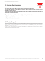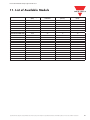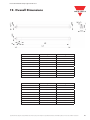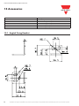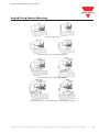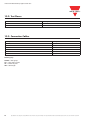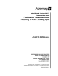
1
CARLO GAVAZZI
Au t o m a t i o n
C o m p o n e n t s
Safety Light Curtain with infrared beams SC2 type
Instruction manual
Instruction Manual Safety Light Curtain SC2
ORIGINAL INSTRUCTIONS (ref. 2006/42/EC)
CARLO GAVAZZI LOGISTICS S.p.A.
Headquarter: Via Milano 13, I-20020 Lainate (MI)
Tel.: +39 02 93176.1, Fax +39 02 9176.403
Internet: http://www.gavazziautomation.com
SC2 Instruction Manual
Ed. 03/2013
All brand and product names mentioned herein are for identification purposes only and may be
trademarks or registered trademarks of their respective owners.
Carlo Gavazzi shall not be liable for technical or editorial errors or omissions contained herein,
not for incidental or consequential damages resulting from the use of this material.
Specifications are subject to change without notice. Pictures are just an example. For special features and/or customization, please ask to our sales network. 20/01/2014
Instruction Manual Safety Light Curtain SC2
Specifications are subject to change without notice. Pictures are just an example. For special features and/or customization, please ask to our sales network. 20/01/2014
Instruction Manual Safety Light Curtain SC2
Index
1. GENERAL INFORMATION1
1.1. General description of the safety light curtains
4
1.1.1. Package contents
5
1.2. New features compared to the SB2 Series
6
1.3. How to choose the device
7
1.3.1. Resolution
7
1.3.2. Controlled height8
1.3.3. Minimum installation distance
9
1.4. Typical applications
12
1.5. Safety information
14
2. INSTALLATION MODE
2.1. Precautions to be observed for the choice and installation of the device
2.2. General information on device positioning
2.2.1. Minimum installation distance
2.2.2. Minimum distance from reflecting surfaces
2.2.3. Emitter and receiver orientation
2.2.4. Installation of several adjacent safety light curtains
2.2.5. Use of deviating mirrors
2.2.6. Controls after first installation
15
15
16
17
18
20
21
22
23
3. MECHANICAL MOUNTING
24
4. ELECTRICAL CONNECTIONS
4.1. Notes on connections
4.2. Earth connection
27
28
30
5. ALIGNMENT PROCEDURE
5.1. Correct alignment procedure
31
33
6. FUNCTIONING MODE
6.1. Reset mode
6.2. Test function
6.3. Reset function
34
34
34
34
7. DIAGNOSTIC FUNCTIONS
7.1. User interface
7.2. Diagnostic messages
35
35
36
8. PERIODICAL CHECKS
8.1. General information and useful data
8.2. Warranty
37
38
38
9. DEVICE MAINTENANCE
9.1. Product disposal
39
39
2
Specifications are subject to change without notice. Pictures are just an example. For special features and/or customization, please ask to our sales network. 20/01/2014
Instruction Manual Safety Light Curtain SC2
10. TECHNICAL DATA
40
11. LIST OF AVAILABLE MODELS
41
12. OVERALL DIMENSIONS
43
13. ACCESSORIES
13.1. Angled fixing bracket
13.2. Test pieces
13.3. Connection cables
44
44
46
46
14. GLOSSARY
47
Specifications are subject to change without notice. Pictures are just an example. For special features and/or customization, please ask to our sales network. 20/01/2014
3
Instruction Manual Safety Light Curtain SC2
1. General Information
1.1. General Description of the Safety Light Curtains
The safety light curtains of the SC2 series are optoelectronic multibeam devices that are used to protect
working areas that, in presence of machines, robots, and automatic systems in general, can become
dangerous for operators that can get in touch, even accidentally, with moving parts. The light curtains
of the SC2 series are Type 2 intrinsic safety systems used as accident-prevention protection devices
and are manufactured in accordance with the international Standards in force for safety, in particular:
CEI IEC 61496-1: 2004
Safety of machinery: electro-sensitive protective equipment. Part 1: General prescriptions and tests.
CEI IEC 61496-2: 2006
Safety of machinery: electro-sensitive protective equipment. Particular requirements for equipment using active optoelectronic protective devices.
The device, consisting of one emitter and one receiver housed inside strong aluminium profiles, generates
infrared beams that detect any opaque object positioned within the light curtain detection field. The
emitter and the receiver are equipped with the command and control functions. The connections are
made through a M12 connector located in the lower side of the profile. The synchronisation between
the emitter and the receiver takes place optically, i.e. no electrical connection between the two units is
required. The microprocessor guarantees the check and the management of the beams that are sent
and received through the units. The microprocessor – through some LEDs – informs the operator about
the general conditions of the safety light curtain (see section 7 “Diagnostic functions”). The device
consists in 2 units that, according to the model, are composed by one or several emitting and receiving
modules. The receiver checks the control operations and safety actions.
During installation, two yellow LEDs facilitate the alignment of both units (see section 5 “Alignment
procedure”). As soon as an object, a limb or the operator’s body accidentally interrupts one or some of
the infrared beams sent by the emitter, the receiver immediately opens the OSSD outputs and blocks
the MPCE machine (if correctly connected to the OSSD).
Some parts or sections of this manual containing important information for the operator are preceded
by a note.
Notes and detailed descriptions about particular characteristics of the safety devices in order to
better explain their functioning. Special instructions regarding the installation process.
4
Specifications are subject to change without notice. Pictures are just an example. For special features and/or customization, please ask to our sales network. 20/01/2014
Instruction Manual Safety Light Curtain SC2
The information provided in the paragraphs following this symbol is very important for safety
and may prevent accidents. Always read this information accurately and carefully follow the
advice to the letter.
This manual contains all the information necessary for the selection and operation of the safety devices.
However, specialised knowledge not included in this technical description is required for the planning
and implementation of a safety light curtain on a power-driven machine. As the required knowledge may
not be completely included in this manual, we suggest the customer to contact Carlo Gavazzi Technical
Service for any necessary information relative to the functioning of the SC2 light curtains and the safety
rules that regulate the correct installation (see section 8 “Periodical checks”).
Specifications are subject to change without notice. Pictures are just an example. For special features and/or customization, please ask to our sales network. 20/01/2014
5
Instruction Manual Safety Light Curtain SC2
1.1.1. Package Contents
Package contains the following objects:
• Receiver (RX)
• Emitter (TX)
• Quick Guide for first installation
• CD with user manual and other documents
• Checklist and periodical maintenance schedule
• 4 angled fixing brackets and specific fasteners
• 2 angled fixing brackets for models with heights included between 1200 and 1500 mm
1.2. New Features Compared to the Former SB2 Series
6
The SC2 safety light curtains, compared to the SB2 series, present the following new features:
• Increased operating distance
• Range enlargement with 300 to 1500 mm controlled heights
• Reduced response times
• New fastening system with rotating brackets
• New mechanical profile compatible with SB accessories
• Different positioning of synchronisation optics (the first one from the reference line)
• Different mechanical mounting
Specifications are subject to change without notice. Pictures are just an example. For special features and/or customization, please ask to our sales network. 20/01/2014
Instruction Manual Safety Light Curtain SC2
1.3. How to Choose the Device
1.3. How to choose the device
There are at least three different main characteristics that should be considered when choosing
a safety light curtain, after having evaluated the risk assessment:
1.3.1. Resolution
The resolution of the device is the minimum dimension that an opaque object must have in
order to obscure at least one of the beams that constitute the sensitive area.
The resolution strictly depends on the part of the body to be protected
R = 30 mm
Hand protection
Type 2
R = 90mm
Presence control
As shown in Fig.1, the resolution only depends on the geometrical characteristics of the
lenses, diameter and distance between centres, and is independent from any environmental
and operating conditions of the safety light curtain.
Fig.1
The resolution value is obtained applying the following formula:
R=I+d
where:
I = Distance between two adjacent optics
d=
Lens diameter
Specifications are subject to change without notice. Pictures are just an example. For special features and/or customization, please ask to our sales network. 20/01/2014
7
Instruction Manual Safety Light Curtain SC2
1.3.2. Controlled Height
The controlled height is the height protected by the safety light curtain ( Hp )
Fig.2
The SC2 controlled height is delimited by the yellow line pad-printed on the front glass and by
the dimensions listed in the table:
Hp
Reference
Hp
Reference
8
Model
Controlled height Hp (mm)
SC2-AR-30-150-D19
150
SC2-AR-30-300-D19
300
SC2-AR-30-450-D19
450
SC2-AR-30-600-D19
600
SC2-AR-30-750-D19
750
SC2-AR-30-900-D19
900
SC2-AR-30-1050-D19
1050
SC2-AR-30-1200-D19
1200
SC2-AR-30-1350-D19
1350
SC2-AR-30-1500-D19
1500
Model
Controlled height Hp (mm)
SC2-AR-90-300-D19
300
SC2-AR-90-450-D19
450
SC2-AR-90-600-D19
600
SC2-AR-90-750-D19
750
SC2-AR-90-900-D19
900
SC2-AR-90-1050-D19
1050
SC2-AR-90-1200-D19
1200
SC2-AR-90-1350-D19
1350
SC2-AR-90-1500-D19
1500
Specifications are subject to change without notice. Pictures are just an example. For special features and/or customization, please ask to our sales network. 20/01/2014
Instruction Manual Safety Light Curtain SC2
1.3.3. Minimum Installation Distance
The safety device must be positioned at a specific safety distance (Fig. 3). This distance must
ensure that the dangerous area cannot be reached before the dangerous motion of the machine
has been stopped by the ESPE (Electro Sensitive Protective Equipment).
The safety distance depends on 4 factors, according to the EN-999 Standard:
•
Response time of the ESPE (the time between the effective beam interruption and the opening of the OSSD contacts).
•
Machine stopping time (the time between the effective opening of the contacts of the ESPE and the real stop of the dangerous motion of the machine).
•
ESPE resolution.
•
Approaching speed of the object to be detected.
s
H2
H1
Fig.3
The following formula is used for the calculation of the safety distance:
S = K (t1 + t2) + C
where:
S =Minimum safety distance in mm.
K =Speed of the object, limb or body approaching the dangerous area in mm/sec.
t1= Response time of the ESPE in seconds (see section 9 “Technical data”)
t2= Machine stopping time in seconds.
d =Resolution of the system.
C =Additional distance based on the possibility to insert the body or one of body parts inside the dangerous area before the protective device trips.
C =8 (d -14) for devices with resolution ≤ 40mm
C =850 mm for devices with resolution ≥ 40mm.
NOTE: K value is:
2000 mm/s if the calculated value of S is ≤ 500 mm
1600 mm/s if the calculated value of S is > 500 mm
Specifications are subject to change without notice. Pictures are just an example. For special features and/or customization, please ask to our sales network. 20/01/2014
9
Instruction Manual Safety Light Curtain SC2
When devices with >40 mm resolution are used, the height of the top beam has to be ≥ 900
mm (H2) from machine supporting base while the height of the bottom beam has to be ≤
300 mm (H1). If the safety light curtain must be mounted in a horizontal position (Fig.4), the
distance between the dangerous area and the most distant optical beam must be equal to the
value calculated using the following formula:
S = 1600 mm/s (t1 + t2) + 1200 – 0.4 H
where:
S = Minimum safety distance in mm.
t1 = Response time of the ESPE in seconds (see section 9 “Technical data”)
t2 = Machine stopping time in seconds.
H = Beam height from ground; this height must always be less than 1,000 mm.
s
H
Fig.4
10 Specifications are subject to change without notice. Pictures are just an example. For special features and/or customization, please ask to our sales network. 20/01/2014
Instruction Manual Safety Light Curtain SC2
Practical examples:
Let’s suppose we have a light curtain with height = 600 mm
1)To calculate the distance of the device from the ESPE, in a vertical position, the following
formula is used:
S = K*T + C
where:
T=t1 + t2
t1 = ESPE response time relay release time (max 80 ms)
t2 = Machine total stopping time.
C = 8 * (d – 14) for devices with resolution <= 40 mm
C = 850 for devices with resolution > 40 mm
d = Resolution of the system.
In all cases, if K = 2000mm/sec then S will be > 500 mm.
Distance will have then to be recalculated using K = 1600 mm/sec.
T
SC2-AR-30-600-D19
SC2-AR-90-600-D19
0.398 sec
0.391 sec
C
128 mm
850 mm
S
764.8 mm
1475.6 mm
2) To calculate the distance of the device from the ESPE, in a horizontal position, the following
formula is used:
S = 1600 * T + 1200 – 0.4 * H
where:
H = Beam min. height from ground 15 * (d – 50)
D= Resolution
SC2-AR-90-600-D19
T
-
0.391 sec
H
-
600 mm
S
-
1585.6 mm
WARNING: the reference standard is EN-999 “Machine safety - the positioning of the
protective device based on the approaching speed of the human body”. This information
is just an indication and a kind of summary. For safety distance correct calculation, it is
compulsory to refer to the whole EN999 standard.
Specifications are subject to change without notice. Pictures are just an example. For special features and/or customization, please ask to our sales network. 20/01/2014
11
Instruction Manual Safety Light Curtain SC2
1.4. Typical Application
The safety light curtains of the SC2 series are used in all automation fields where the control and
protection of the access to dangerous areas are necessary.
In particular, they are used to stop the moving of mechanical parts in:
-
-
-
-
-
Automatic machines;
Machines for packaging, material handling, storing;
Weaving machines, wood working machines, ceramic working machines;
Automatic and semiautomatic assembly lines;
Automatic warehouses.
In food industry applications, Carlo Gavazzi Technical Service has to verify the compatibility
of the material of the safety light curtain housing with any chemical agents used in the production process.
Example 1: Hand protection on moulding machines
In order to protect the light curtain against dust and humidity, a IP69K protective enclosure can be
used.
The aim is to prevent operator’s hands from being squashed during the final product stacking
process. In addition, the solution must not interfere with the manufacturing process.
Solution:
The new SC2 safety light curtains present an ideal solution to safely monitor a moulding application,
whilst optimising the manufacturing process.
Advantages:
The use of the new SC2 range ensures the safety of the operator thanks to its enhanced response
time, meeting ergonomic and productivity requirements, as the protected area always remains
accesible when the machine stops.
12
Specifications are subject to change without notice. Pictures are just an example. For special features and/or customization, please ask to our sales network. 20/01/2014
Instruction Manual Safety Light Curtain SC2
Example 2: Cooling and conditioning systems
Cooling and conditioning systems, as well as automotive
equipment and components are checked inside a machine,
to detect possible leaks by a helium mass spectrometer. The
point where these parts are positioned inside the measuring
chamber requires a Type 2 protection ensuring a certain space
saving and an easy access to the protected area.
Solution:
The SC2 safety light curtain series represents the ideal
solution when the safety requirements and the application are
considered. Even when just one of the light curtain beams is
interrupted, the test machine is immediately stopped.
Advantages:
The SC2 light curtain meets the customer’s needs when easy
access is necessary in presence of machine stops. Easy
installation, configuration and use are other advantages.
Example 3: Automatic warehouses
Operator protection in automatic warehouses.
Solution:
The SC2 safety light curtain series represents the ideal solution if the safety requirements and the
application are considered. When even just one of the light curtain beams is interrupted, the carousel
is immediately stopped.
Advantages:
The SC2 light curtain meets the customer’s needs when easy access is necessary in presence of
machine stops. Easy installation, configuration and use are other advantages.
Specifications are subject to change without notice. Pictures are just an example. For special features and/or customization, please ask to our sales network. 20/01/2014
13
Instruction Manual Safety Light Curtain SC2
1.5. Safety Information
For a correct and safe use of the safety light curtains of the SC2 series, the following
points must be observed:
• The stopping system of the machine must be electrically controlled.
• This control system must be able to stop the dangerous movement of the machine within the total machine stopping time T as per section 1.3.3, and during all working cycle phases.
•
•
Mounting and connection of the safety light curtain must be carried out only by qualified personnel, according to the indications included in the special sections (refer to sections 2; 3; 4; 5) and in the applicable Standards.
The safety light curtain must be securely installed in a particular position so that access to the dangerous zone is not possible without the interruption of the beams (see section 2 “Installation mode”).
• The personnel operating in the dangerous area must be well trained and must have adequate knowledge of all the operating procedures of the safety light curtain.
• The TEST button must be located outside the protected area because the operator must check the protected area during all Test and Reset operations.
Please carefully read the instructions for the correct functioning before powering the light curtain.
14 Specifications are subject to change without notice. Pictures are just an example. For special features and/or customization, please ask to our sales network. 20/01/2014
Instruction Manual Safety Light Curtain SC2
2. Installation Mode
2.1. Precautions to be Observed for the Choice and Installation of the Device
Make sure that the protection level assured by the SC2 device (Type 2) is compatible with the real danger level of the machine to be controlled, according to EN 954-1 and EN ISO 13849-1:2008.
• The outputs (OSSD) of the ESPE must be used as machine stopping devices and not as command devices. The machine must have its own START command.
• The dimension of the smallest object to be detected must be larger than the resolution level of the device.
• The ESPE must be installed in a room complying with the technical characteristics indicated in section 10 “Technical data”.
• Do not place the device near intense and/or flashing light sources and, in particular, close to receiving unit front surface.
• The presence of intense electromagnetic disturbances could affect device correct operation. This condition shall be carefully assessed by seeking the advice of Carlo Gavazzi Technical service.
• The operating distance of the device can be reduced in presence of smog, fog or airborne dust.
• A sudden change in environment temperature, with very low minimum peaks, can generate a
small condensation layer on the lenses and so jeopardise functioning.
Specifications are subject to change without notice. Pictures are just an example. For special features and/or customization, please ask to our sales network. 20/01/2014
15
Instruction Manual Safety Light Curtain SC2
2.2. General Information on Device Positioning
The safety light curtain should be carefully positioned, in order to reach a very high protection
standard. Access to the dangerous area must only be possible by passing through the
protecting safety light beams.
Fig. 5a shows some examples of possible access to the machine from the top and the bottom sides. These situations may be very dangerous and so the installation of the safety light curtain at sufficient height in order to completely cover the access to
the dangerous area (Fig.5b) becomes necessary.
NO
Fig.5a
YES
Fig.5b
Under standard operating conditions, machine starting must not be possible while operators
are inside the dangerous area.
16 Specifications are subject to change without notice. Pictures are just an example. For special features and/or customization, please ask to our sales network. 20/01/2014
Instruction Manual Safety Light Curtain SC2
When the installation of the safety light curtain very near to the dangerous area is not possible,
a second light curtain must be mounted in a horizontal position in order to prevent any lateral
access (as shown in Fig.6b).
If the operator is able to enter the dangerous area, an additional mechanical protection
must be mounted to prevent the access.
NO
Fig.6a
YES
Fig.6b
2.2.1. Minimum Installation Distance
Refer to section 1.3.3. “Minimum installation distance”
Specifications are subject to change without notice. Pictures are just an example. For special features and/or customization, please ask to our sales network. 20/01/2014
17
Instruction Manual Safety Light Curtain SC2
2.2.2. Minimum Distance From Reflecting Surface
Reflecting surfaces placed near the light beams of the safety device (over, under or laterally)
can cause passive reflections. These reflections can compromise the recognition of an object
inside the controlled area.
However, if the RX receiver detects a secondary beam (reflected by the side-reflecting surface)
the object might not be detected, even if the object interrupts the main beam.
Fig.7
18 Specifications are subject to change without notice. Pictures are just an example. For special features and/or customization, please ask to our sales network. 20/01/2014
Instruction Manual Safety Light Curtain SC2
It is thus important to position the safety light curtain according to the minimum distance from
reflecting surfaces.
The minimum distance depends on:
• Operating distance between emitter (TX) and receiver (RX);
• Real opening angle of ESPE (EAA); in particular:
for ESPE type 2
EAA = 10° (α = 5°)
Distance from reflecting surface (Dsr)
Diagram of Fig. 8 shows the min. distance from the reflecting surface (Dsr), based on the
operating distance:
m
ESPE
Type2
1.67
0.2 7
0.2 7
3
Operating distance
19
m
Fig.8
The formula to get Dsr is the following:
Dsr (m) = 0.27
for oper. distances < 3 m
Dsr (m) = 0,5 operating distance (m) x tg 2α for oper. distances ≥ 3 m
Specifications are subject to change without notice. Pictures are just an example. For special features and/or customization, please ask to our sales network. 20/01/2014
19
Instruction Manual Safety Light Curtain SC2
2.2.3. Emitter and Receiver Orientation
The two units shall be installed parallel to each other, with the beams orthogonal respect to the
emitting and receiving directions, with the connectors positioned in the same manner.
The configurations shown in Fig. 9 must be avoided:
NO
NO
Fig.9
20 Specifications are subject to change without notice. Pictures are just an example. For special features and/or customization, please ask to our sales network. 20/01/2014
Instruction Manual Safety Light Curtain SC2
2.2.4. Emitter and Receiver Orientation
When several safety devices must be installed in adjacent areas, interferences between the
emitter of one device and the receiver of the other must be avoided.
Fig.10 provides an example of possible interferences between different devices and two
pertinent solutions.
NO
TX
RX
TX
RX
TX
RX
TX
RX
TX
RX
TX
RX
Opaque surface
YES
YES
Fig.10
Specifications are subject to change without notice. Pictures are just an example. For special features and/or customization, please ask to our sales network. 20/01/2014
21
Instruction Manual Safety Light Curtain SC2
2.2.5. Use of Deviating Mirrors
The control of any dangerous area, with several but adjacent access sides, is possible using
only one safety device and well-positioned deviating mirrors.
Fig.11 shows a possible solution to control three different access sides, using two mirrors
placed at 45° with respect to the beams.
RX
TX
S
D3
DANGEROUS
AREA
S
D1
S
mirror
mirror
D2
Fig.11
The operator must respect the following precautions when using the deviating mirrors:
• The alignment of the emitter and the receiver can be a very critical operation when deviating mirrors are used. Even a very small mirror displacement is enough to lose alignment.
• The minimum safety distance (S) must be respected for each single section of the beams.
• The effective operating range decreases by about 15% by using only one deviating mirror, the percentage further decreases by using 2 or more mirrors (for more details refer to the technical specifications of the mirrors used).
The following table shows the operating distances relating to the number of mirrors used.
Number of mirrors
1
2
3
Operating distance
16.5 m
13.7 m
11.6 m
• Do not use more than three mirrors for each device.
• The presence of dust or dirt on the reflecting surface of the mirror causes a drastic reduction in the range.
22 Specifications are subject to change without notice. Pictures are just an example. For special features and/or customization, please ask to our sales network. 20/01/2014
Instruction Manual Safety Light Curtain SC2
2.2.6. Controls After Installation
• The control operations to carry-out after the first installation and before machine start-up are listed hereinafter. The controls must be carried-out by qualified personnel, either directly
or under the strict supervision of the person in charge of machinery Safety.
Verify that:
• ESPE remains blocked ( I ) intercepting the beams along the protected area using the specific test piece, following the Fig.12 scheme.
TP30 for light curtains with 30 mm resolution for example:
GO
SC2-AR-30-150-D19
END
Fig.12
• ESPE has to be correctly aligned, press slightly on the product side in both directions the
red LED must not turn on
I.
• The activation of the TEST function causes the opening of the OSSD outputs (red LED I
on and controlled machine stop).
• The response time at machine STOP, including the ESPE and machine response times,
must be included in the limits defined in the calculation of the safety distance (refer to
section 2 “Installation modes”).
• The safety distance between the dangerous parts and ESPE must comply with the
requirements indicated in section 2 “Installation modes”.
• A person must not access or remain between ESPE and the dangerous parts of the machine.
• Access to the dangerous areas of the machine must not be possible from any unprotected
area.
• ESPE must not be disturbed by external light sources, ensuring that it remains in Normal operating function for at least 10-15 minutes and placing the specific test piece in the
protected area in the SAFE condition for the same period.
• Verify the correspondence of all the accessory functions, activating them in the different
operating conditions.
Specifications are subject to change without notice. Pictures are just an example. For special features and/or customization, please ask to our sales network. 20/01/2014
23
Instruction Manual Safety Light Curtain SC2
3. Mechanical Mounting
The emitting (TX) and receiving (RX) units must be installed with the relevant sensitive surfaces
facing each other. The connectors must be positioned on the same side and the distance must
be included within the operating range of the model used (see section 10 “Technical data”).
The two units must be positioned the most aligned and parallel possible.
The next step is the fine alignment, as shown in section 5 “Alignment Procedure”.
Two types of brackets can be used to fix the two units:
Angled fixing brackets
Angled fixing brackets are supplied with all SC2 models (Fig.13).
Adjustable supports for correcting unit inclination on the axes are available on request (see
section.14 “Accessories”).
For fixing with angled brackets, refer to Fig.13.
Fig.13
24 Specifications are subject to change without notice. Pictures are just an example. For special features and/or customization, please ask to our sales network. 20/01/2014
Instruction Manual Safety Light Curtain SC2
Rotating brackets
Rotating brackets (Fig.14), available upon request, can be used as an alternative or together
with angled brackets.
For fixing with rotating bracket, refer to Fig.14.
Fig.14
In case of applications with particularly strong vibrations, vibration dampers, together with
mounting brackets, are recommended to reduce the impact of the vibrations.
Fig.15
The recommended mounting positions according to the light curtain length are shown in Fig.15
and in the following table.
Specifications are subject to change without notice. Pictures are just an example. For special features and/or customization, please ask to our sales network. 20/01/2014
25
Instruction Manual Safety Light Curtain SC2
Models
L (mm)
A (mm)
B (mm)
683C (mm)
SC2-AR-30-150-D19
216.3
108
54
-
SC2-AR-30-300-D19
366.2
216
75
-
SC2-AR-30-450-D19
516.3
316
100
-
SC2-AR-30-600-D19
666.2
366
150
-
SC2-AR-30-750-D19
816.3
466
175
-
SC2-AR-30-900-D19
966.2
566
200
-
SC2-AR-30-1050-D19
1116.2
666
225
-
SC2-AR-30-1200-D19
1266.3
966
150
483
SC2-AR-30-1350-D19
1416.2
1066
175
533
SC2-AR-30-1500-D19
1566.3
1166
200
533
Models
L (mm)
A (mm)
B (mm)
683C (mm)
SC2-AR-90-300-D19
366.2
216
75
-
SC2-AR-90-450-D19
516.3
316
100
-
SC2-AR-90-600-D19
666.2
366
150
-
SC2-AR-90-750-D19
816.3
466
175
-
SC2-AR-90-900-D19
966.2
566
200
-
SC2-AR-90-1050-D19
1116.2
666
225
-
SC2-AR-90-1200-D19
1266.3
966
150
483
SC2-AR-90-1350-D19
1416.2
1066
175
533
SC2-AR-90-1500-D19
1566.3
1166
200
533
26 Specifications are subject to change without notice. Pictures are just an example. For special features and/or customization, please ask to our sales network. 20/01/2014
Instruction Manual Safety Light Curtain SC2
4. Electrical Connection
All electrical connections to the emitting and receiving units are made through a male M12
connector, located on the lower part of the two units. For receiver a M12 5-pole connector is
used, while for emitter a M12 4-pole connector is used.
RECEIVER (RX):
OSSD1
2
+24VDC
1
TEST / RESET
5
0V
1
2
3
4
5
= Brown=
= White =
=Blue =
= Black =
=Grey =
OSSD1
+24VDC
OSSD 1
0V
OSSD 2
NOT USED
0V
TEST/RESET
3
4
2
1
OSSD2
+24VDC
TEST / RESET
5
EMITTER (TX)
4
3
2
1
OSSD2
+24VDC
EMITTER (TX):
0V
NOT USED
0V
1
2
3
4
= Brown=
= White =
=Blue =
= Black =
3
4
EMITTER (TX)
2
1
3
4
NOT USED
+24VDC
NOT USED
+24VDC
NOT USED
0V
NOT USED
Specifications are subject to change without notice. Pictures are just an example. For special features and/or customization, please ask to our sales network. 20/01/2014
27
Instruction Manual Safety Light Curtain SC2
4.1. Notes of Connections
For the correct functioning of the SC2 safety light curtains, the following precautions regarding
the electrical connections have to be respected:
• Do not place connection cables in contact with or near high-voltage cables and/or cable
undergoing high current variations (e.g. motor power supplies, inverters, etc.);
Do not connect in the same multi-pole cable the OSSD wires of different light curtains;
• The TEST/RESET wire must be connected through a N.O. button to the supply voltage of
the ESPE.
The TEST/RESET button must be located in such a way that the operator can check the protected area during any Test and Reset operation. (see section 6 “Functioning mode”).
• The device is protected internally against overvoltage and overcurrent. The use of other
external components is not recommended.
Example: connection with safety relay
The figures show the connection between the safety light curtains and a safety relay functioning
in the Automatic Start mode (left side) and Manual Start with monitoring (right side).
Do not use varistors, RC circuits or LEDs in parallel at relay inputs or in series at OSSD
outputs.
• The OSSD1 and OSSD2 safety contacts cannot be connected in series or in parallel, but
can be used separately (Fig.16).
If one of these configurations is erroneously used, the device enters into the output failure
condition (see section 7 “Diagnostic functions”).
28 Specifications are subject to change without notice. Pictures are just an example. For special features and/or customization, please ask to our sales network. 20/01/2014
Instruction Manual Safety Light Curtain SC2
• Connect both OSSDs to the activating device. Failure to connect an OSSD to the activating
device jeopardises the system safety degree that the light curtain has to control
+24VDC
+24VDC
YES
YES
NO
NO
OSSD1
OSSD1
+24VDC
+24VDC
OSSD2
OSSD2
Fig.16
Fig.17
+24VDC
NO
NO
NO
NO
+24VDC
OSSD1
+24VDC
OSSD1
OSSD2
+24VDC
OSSD2
Fig.18
Fig.19
Specifications are subject to change without notice. Pictures are just an example. For special features and/or customization, please ask to our sales network. 20/01/2014
29
Instruction Manual Safety Light Curtain SC2
4.2. Earth Connection
SC2 safety light curtain units are preset for easy ground connection. A special compartment,
positioned onto caps and marked with the special symbol shown in Figure 20, allows connection
with ground cable by means of an additional screw coming with the equipment.
Fig.20
Ground connection configuration is the most common and guarantees the best immunity
against electromagnetic disturbances. SC2 can function even without ground connection.
This condition has to be carefully evaluated according to the EMC disturbance immunity and
necessary insulation class considering the plant or entire system where the light curtain is
installed.
•
•
The ground connection of the two units is not necessary for Class III, while the use of a duly
insulated low-voltage feeder type SELV or PELV is compulsory. In this case, we recommend
covering the earth symbol present on the caps of the two units with a blank sticker.
The ground connection of the two units is compulsory for Class I, while the use of a duly
insulated feeder type SELV or PELV is not compulsory but anyway recommended.
The following table is a summary of SC2 electrical protections.
Electrical protection
Class I
Class III
Ground connection
Compulsory
Not necessary
Ground connection symbol
Compulsory
Not necessary
Power supply by generators SELV /
PELV
Recommended
Compulsory
30 Specifications are subject to change without notice. Pictures are just an example. For special features and/or customization, please ask to our sales network. 20/01/2014
Instruction Manual Safety Light Curtain SC2
5. Alignment Procedure
The alignment between the emitting and the receiving units is necessary to obtain the correct
functioning of the light curtain.
A good alignment prevents outputs instability caused by dust or vibrations.
The alignment is perfect if the optical axes of the first and the last emitting unit’s beams
coincide with the optical axes of the corresponding elements of the receiving unit.
The beam used to synchronise the two units is the first after the connector. SYNC is the optics
connected with this beam and LAST is the optics connected to the last beam after the SYNC
unit.
Last optics (LAST)
First Optics = Synchrinisation
optics (SYNC)
Receiver
NORMAL
OP.
LAST
Fig.21
SAFE
SYNC
(BREAK)
Signals are clearly identified through symbols allowing immediate reading, independent of bars
directions. A short description of the signalling LEDs is necessary to avoid misunderstandings.
Receiver
Emitter
NORMAL
OP.
LAST
SAFE
(BREAK)
SYNC
NORMAL
OP.
ON
Fig.22
Emitter
Specifications are subject to change without notice. Pictures are just an example. For special features and/or customization, please ask to our sales network. 20/01/2014
31
Instruction Manual Safety Light Curtain SC2
The standard installation described hereinafter is the one shown in Fig. 22, i.e. with the bar
assembled with the connectors pointing down.
Two yellow LEDs (p LAST, q SYNC) on SC2 receiver, facilitates the alignment procedure.
During standard operation, the LEDs indicate the safety light curtain status, as shown in the
table.
FUNCTIONING STATUS
LED colour
Symbol
Yellow
p
q
Stop
Status
NORMAL OP.
OFF
ON
OFF
OFF
OFF
ON
ON
OFF
Red
OFF
ON
ON
ON
Green
ON
OFF
OFF
Yellow
- Standard
condition:
- Not interrupted
beams
32 Stop
Status
SAFE (BREAK)
- Units not aligned
- Bottom side not
- Top side not
aligned
aligned
- Lowest beam
- Highest beam
interrupted
interrupted
OFF
Units aligned, but
at least one of beams (the highest
and lowest excluded) is interrupted
Specifications are subject to change without notice. Pictures are just an example. For special features and/or customization, please ask to our sales network. 20/01/2014
Instruction Manual Safety Light Curtain SC2
5.1. Correct Alignment Procedure
The light curtain alignment can be effected only after having completed the mechanical
installation and the electrical connections. The following procedure has to be followed:
•
•
•
Check the green LED (<) and the yellow LED ( ) on the TX unit. If ON, the emitter is
running correctly;
Verify that the sensitive area from the safety light curtain is free;
Verify that one of the following conditions is present on the RX unit:
1.STANDARD CONDITION - NORMAL OP.
Green LED (
) ON and red LED (
I) OFF.
Both yellow LEDs (p,q) are OFF.
Units are aligned.
2.STOP CONDITION - SAFE (BREAK)
Green LED (
) OFF and red LED (
I) ON.
The status of both yellow LEDs (p,q) does not matter.
Units are not aligned.
Continue with the following steps to pass from condition 2 to condition 1:
- Keep the receiver in a steady position and set the emitter until the yellow LED (qSYNC)
is OFF. This condition shows the effective alignment of the first synchronisation beam.
- Rotate the emitter, pivoting on the lower optics axis, until the yellow LED (pLAST) is OFF.
Under these conditions, the SAFE LED shall turn ON.
NOTE: Ensure that the green LED
is steady ON.
- Delimit the area in which the LED
is steady through some micro adjustments - for the
first and then for the second unit - then place both units in the centre of this area.
•
•
•
Fix the two units firmly using brackets.
Verify that the green LED on the RX unit is ON ( I) and beams are not interrupted, then
verify that the red LED turns ON if even one single beam is interrupted (condition where an
object has been detected).
This verification shall be made with the special cylindrical “Test Piece” having a size suitable
to the resolution of the device used.
NOTE: Passing the Test Piece along the whole sensitive area and at any distance from
the two units, the red LED (
I) shall be always ON and never change status.
A daily test is recommended.
Specifications are subject to change without notice. Pictures are just an example. For special features and/or customization, please ask to our sales network. 20/01/2014
33
Instruction Manual Safety Light Curtain SC2
6. Function Mode
6.1. Reset Mode
The interruption of a beam due to an opaque object causes the opening of OSSD outputs and
the stop of the safety light curtain SAFE (BREAK) condition
I.
The ESPE will automatically restart its standard operation (NORMAL OP. condition ) as soon
as the object is removed.
WARNING: Carefully assess risk conditions and reset modes.
In applications protecting access to dangerous areas, the automatic reset mode is potentially
unsafe if it allows the operator to pass completely beyond the sensitive area (see Fig. 6b).
In this case, the reset, using for example the manual reset of the relay, (page 26) might be
necessary.
6.2. Test Function
The TEST function can be activated by keeping a normally open external contact (TEST pushbutton), closed for at least 0.5 seconds.
The TEST signal is active high.
OSSD
ON
OFF
24VDC
TEST
0VDC
0.5 SEC
6.3. Reset Function
The RX light curtain has a RESET function which is activated after an internal error. The reset
can be made only in case of optical error or OSSD error (See sect. 7 “Diagnostic Functions”)
The RESET function can be activated by keeping a normally open external contact (RESET/
RESTART push-button), closed for at least 5 seconds.
The RESET signal is active high.
Safety light curtain status
Faulty block
Standard operating mode
24VDC
TEST
0VDC
5 SEC
34 Specifications are subject to change without notice. Pictures are just an example. For special features and/or customization, please ask to our sales network. 20/01/2014
Instruction Manual Safety Light Curtain SC2
7. Diagnostic Function
7.1. User Interface
The operator can visualise the operating condition of the light curtains through the four LEDs
positioned on the receiver unit and two LEDs on the emitter unit.
Fig.23 shows all signalling LEDs modes: OFF, ON and BLINKING.
LED OFF
LED ON
LED BLINKING
Fig.23
Specifications are subject to change without notice. Pictures are just an example. For special features and/or customization, please ask to our sales network. 20/01/2014
35
Instruction Manual Safety Light Curtain SC2
7.2. Diagnostic Messages
The operator is able to check the main causes of the system stop and failure, using the same
LEDs used for visualising the functions.
For receiver:
Function
Nomal
operation
Status
TEST
(red ON)
Light curtain being tested, the OSSD status
shall be OFF
Emission (OSSD ON) (green ON)
Light curtain working and in normal operating conditions
Interruption (OSSD OFF) (red ON)
Light curtain working and in safety block
conditions.
Function
Error
Status
Meaning
Type
Check and repair
OSSD error (yellow and red
BLINKING)
Check OSSD connections; make sure that
they are not in contact with one another or
with the supply cables, then Reset. If the
failure continues contact Carlo Gavazzi
Internal error (red ON yellow
BLINKING)
Switch OFF and switch ON the supply circuit; if the failure continues contact Carlo
Gavazzi
Optical error (red ON yellow
BLINKING)
Reset. If the failure continues contact Carlo Gavazzi
No power supply (LEDs OFF)
Check connections and input voltage correct value. If the failure continues contact
Carlo Gavazzi
LED
LED
For emitter:
Function
Status
Test (green ON)
Nomal
operation
Function
Error
Status
Emission
(green ON
yellow ON)
LED
Light curtain being tested, the OSSD status
shall be OFF
Light curtain working and in normal operating conditions
Type
Check and repair
Internal error (green ON yellow
BLINKING)
Switch OFF and switch ON the supply circuit; if the failure continues contact Carlo
Gavazzi
Optical error (green ON yellow
blinking)
Switch OFF and switch ON the power
supply circuit. If the failure continues contact Carlo Gavazzi
No power supply
(LEDs OFF)
36 Meaning
LED
Check connections and input voltage correct value. If the failure continues contact
Carlo Gavazzi
Specifications are subject to change without notice. Pictures are just an example. For special features and/or customization, please ask to our sales network. 20/01/2014
Instruction Manual Safety Light Curtain SC2
8. Periodical Checks
The following is a list of recommended check and maintenance operations that should be
periodically carried out by qualified personnel.
Check that:
• The ESPE stays locked ( I) during beam interruption along the entire protected area, using the suitable “Test Piece”. (*)
• The ESPE is correctly aligned: by slightly pressing product side, in both directions, the red
LED shall not come ON
I.
• Enabling the TEST function, the OSSD outputs should open (the red LED I is ON and the controlled machine stops).
• The response time upon machine STOP (including response time of the ESPE and of the
machine) is within the limits defined for the calculation of the safety distance (see section 2
“Installation mode”).
• The safety distance between the dangerous areas and the ESPE are in accordance with the
instructions included in section 2 “Installation mode”.
• Access of a person between ESPE and machine dangerous parts is not possible nor is it
possible for him/her to stay there.
• Access to the dangerous area of the machine from any unprotected area is not possible.
• The ESPE and the external electrical connections are not damaged.
The frequency of checks depends on the particular application and on the operating conditions
of the safety light curtain.
(*) according to the Fig.12 scheme
Verify that:
• ESPE remains blocked ( I) intercepting the beams along the protected area using the specific test piece, following the Fig.12 scheme.
TP30 for light curtains with 30 mm resolution for example: SC2-AR-30-150-D19
Specifications are subject to change without notice. Pictures are just an example. For special features and/or customization, please ask to our sales network. 20/01/2014
37
Instruction Manual Safety Light Curtain SC2
8.1. General Information and Useful Data
Safety MUST be a part of our conscience.
The safety devices fulfil their safety function only if they are correctly installed, in accordance
with the Standards in force.
If you are not certain to have the expertise necessary to install the device in the correct way,
Carlo Gavazzi Customer Service is at your disposal to carry out the installation.
The device uses fuses that are not self-resetting. Consequently, in presence of short-circuits
causing the cut-off of these fuses, both units shall be sent to Carlo Gavazzi service department.
A power failure caused by interferences may cause the temporary opening of the outputs, but
the safe functioning of the light curtain will not be compromised.
8.2. Warranty
Carlo Gavazzi guarantees each brand new SC2 system, under standard use conditions, against
manufacturing defects in material and workmanship for a period of 36 (thirty-six) months from
the date of manufacturing.
Carlo Gavazzi will not be liable for any damages to persons and things caused by failure to
stick to the correct installation modes and device use.
Warranty validity is subject to the following conditions:
• User shall notify Carlo Gavazzi the failure within thirty-six months from product manufacturing
date.
• Failure or malfunction shall not have been originated directly or indirectly by:
• use for unsuitable purposes;
• failure to comply with the intended use prescriptions;
• negligence, unskillfulness, wrong maintenance;
• repairing, changes, adaptations not made by Carlo Gavazzi personnel, tampering with the
device, etc.;
• accidents or crashes (even due to transportation or by force majeure causes);
• other causes not depending from Carlo Gavazzi
If the device does not work, send both units (receiver and emitter) to Carlo Gavazzi. The
Customer is responsible for all transport charges and damage risks or material loss during
transport, unless otherwise agreed.
All replaced products and parts become a property of Carlo Gavazzi.
Carlo Gavazzi does not accept any warranty or right other than the above-described ones.
No requests for compensation for expenses, activities stop or other factors or circumstances
somehow connected to the failure of the product or one of its parts to operate cannot be put
forward for any reason.
In case of problems, please contact Carlo Gavazzi Service Department:
Tel: +39 02 931 761
Fax: +39 02 931 763 01
38 Specifications are subject to change without notice. Pictures are just an example. For special features and/or customization, please ask to our sales network. 20/01/2014
Instruction Manual Safety Light Curtain SC2
9. Device Maintenance
SC2 safety light curtains do not require special maintenance operations.
To avoid the reduction of the operative distance, optics protective front surfaces shall be
cleaned at regular intervals.
To this end, use soft cotton cloths damped in water; do not apply too much pressure onto the
surface so as not to make it dull.
Please do not use on plastic surfaces or light curtain painted surfaces:
• Alcohol or solvents
• Wool or synthetic cloths
• Paper or other abrasive materials
9.1. Product Disposal
Under current Italian and European laws, Carlo Gavazzi is not obliged to take care of product
disposal at the end of its life.
Carlo Gavazzi recommends to dispose of the product in compliance with local laws or contact
authorised waste collection centres.
Specifications are subject to change without notice. Pictures are just an example. For special features and/or customization, please ask to our sales network. 20/01/2014
39
Instruction Manual Safety Light Curtain SC2
10. Technical Data
The product technical specifications are given below.
ELECTRICAL DATA
Power supply (Vdd):
24 Vdc ± 20%
Unit current draw (TX):
2 W max
Unit current draw (RX):
3.5 W max (without load)
Outputs:
2 PNP
Short-circuit protection:
1.4 A max
Output current:
0.5 A max / each output
Output voltage - status ON:
Vdd - 1 V min
Output voltage - status OFF:
0.2 V max
Capacitive load:
2.2 uF @ 24VDC max
Response times:
See table below
Protected height:
150... 1500mm
Safety category:
Type 2
Auxiliary functions:
Reset / Test
Electrical protection:
Class I / Class III
Connections:
M12-4 poles for emitter
M12-5poles for receiver
Cables length (for power supply):
50 m. max
OPTICAL DATA
Emitting light :
Infrared, LED (950 nm)
Resolution:
30 - 90
Operating distance:
0.2...19m
Ambient light rejection:
IEC-61496-2
MECHANICAL AND ENVIRONMENTAL DATA
Operating temperature:
-10... + 55°C
Storage temperature:
-25... + 70°C
Humidity:
15... 95% (no condensation)
Mechanical protection:
IP 65 (EN 60529)
Vibrations:
Width 0.35 mm, Frequency 10 … 55 Hz
20 sweep per axis, 1octave/min
(EN 60068-2-6)
Shock resistance:
16 ms (10 G) 1,000 shocks per axis
(EN 60068-2-29)
Housing material:
Painted aluminium (yellow RAL 1003)
Front side material:
PMMA
Caps material:
PC MAKROLON
Weight (single unit):
1.3 kg / linear metre
40 Specifications are subject to change without notice. Pictures are just an example. For special features and/or customization, please ask to our sales network. 20/01/2014
Instruction Manual Safety Light Curtain SC2
11. List of Available Models
Model
Protected height
(mm)
Number
of beams
Response time
(msec)
Resolution
(mm)
SC2-AR-30-150-D19
SC2-AR-30-300-D19
150
8
8
30
300
16
9
30
SC2-AR-30-450-D19
450
24
11
30
SC2-AR-30-600-D19
600
32
12
30
SC2-AR-30-750-D19
750
40
14
30
SC2-AR-30-900-D19
900
48
15
30
SC2-AR-30-1050-D19
1050
56
17
30
SC2-AR-30-1200-D19
1200
64
18
30
SC2-AR-30-1350-D19
1350
72
20
30
SC2-AR-30-1500-D19
1500
80
21
30
SC2-AR-90-300-D19
300
5
9
90
SC2-AR-90-450-D19
450
7
10
90
SC2-AR-90-600-D19
600
9
11
90
SC2-AR-90-750-D19
750
11
12
90
SC2-AR-90-900-D19
900
13
13
90
SC2-AR-90-1050-D19
1050
15
14
90
SC2-AR-90-1200-D19
1200
17
15
90
SC2-AR-90-1350-D19
1350
19
16
90
SC2-AR-90-1500-D19
1500
21
17
90
Specifications are subject to change without notice. Pictures are just an example. For special features and/or customization, please ask to our sales network. 20/01/2014
41
SC2-AR-30-150-D19
d
2
2
2
SC2-AR-30-300-D19
d
2
2
SC2-AR-30-450-D19
d
2
2
SC2-AR-30-600-D19
d
2
SC2-AR-30-750-D19
d
2
SC2-AR-30-900-D19
d
SC2-AR-30-1050-D19
SC2-AR-30-1200-D19
Hardware fault
tolerance
SIL CL
Safe failure
fraction
SIL
Average
diagnostic
coverage
EN IEC 62061
CAT
Mean time to
dangerous
failure
EN IEC 61508
PL
Life span
EN 954-1
Product
Prob. of danger
failure/hour
EN ISO 13849-1:2008
Instruction Manual Safety Light Curtain SC2
PFHd
(1/h)
T1
(years)
MTTFd
(years)
DC
SFF
HFT
1,04E-08
20
273
97,50%
98,40%
0
2
1,04E-08
20
273
97,50%
98,40%
0
2
1,04E-08
20
273
97,50%
98,40%
0
2
2
1,04E-08
20
273
97,50%
98,40%
0
2
2
1,04E-08
20
273
97,50%
98,40%
0
2
2
2
1,04E-08
20
273
97,50%
98,40%
0
d
2
2
2
1,04E-08
20
273
97,50%
98,40%
0
d
2
2
2
1,04E-08
20
273
97,50%
98,40%
0
SC2-AR-30-1350-D19
d
2
2
2
1,04E-08
20
273
97,50%
98,40%
0
SC2-AR-30-1500-D19
d
2
2
2
1,04E-08
20
273
97,50%
98,40%
0
SC2-AR-90-300-D19
d
2
2
2
1,04E-08
20
273
97,50%
98,40%
0
SC2-AR-90-450-D19
d
2
2
2
1,04E-08
20
273
97,50%
98,40%
0
SC2-AR-90-600-D19
d
2
2
2
1,04E-08
20
273
97,50%
98,40%
0
SC2-AR-90-750-D19
d
2
2
2
1,04E-08
20
273
97,50%
98,40%
0
SC2-AR-90-900-D19
d
2
2
2
1,04E-08
20
273
97,50%
98,40%
0
SC2-AR-90-1050-D19
d
2
2
2
1,04E-08
20
273
97,50%
98,40%
0
SC2-AR-90-1200-D19
d
2
2
2
1,04E-08
20
273
97,50%
98,40%
0
SC2-AR-90-1350-D19
d
2
2
2
1,04E-08
20
273
97,50%
98,40%
0
SC2-AR-90-1500-D19
d
2
2
2
1,04E-08
20
273
97,50%
98,40%
0
42 Specifications are subject to change without notice. Pictures are just an example. For special features and/or customization, please ask to our sales network. 20/01/2014
Instruction Manual Safety Light Curtain SC2
12. Overall Dimensions
Model
L1
L2
SC2-AR-30-150-D19
233.3
153.3
SC2-AR-30-300-D19
383.2
303.2
SC2-AR-30-450-D19
533.2
453.3
SC2-AR-30-600-D19
683.2
603.2
SC2-AR-30-750-D19
833.2
753.3
SC2-AR-30-900-D19
983.2
903.2
SC2-AR-30-1050-D19
1133.2
1053.2
SC2-AR-30-1200-D19
1283.3
1203.3
SC2-AR-30-1350-D19
1433.2
1353.2
SC2-AR-30-1500-D19
1583.3
1503.3
L1
L2
SC2-AR-90-300-D19
383.2
303.2
SC2-AR-90-450-D19
533.2
453.3
SC2-AR-90-600-D19
683.2
603.2
SC2-AR-90-750-D19
833.2
753.3
SC2-AR-90-900-D19
983.2
903.2
SC2-AR-90-1050-D19
1133.2
1053.2
SC2-AR-90-1200-D19
1283.3
1203.3
SC2-AR-90-1350-D19
1433.2
1353.2
SC2-AR-90-1500-D19
1583.3
1503.3
Model
Specifications are subject to change without notice. Pictures are just an example. For special features and/or customization, please ask to our sales network. 20/01/2014
43
Instruction Manual Safety Light Curtain SC2
13 Accessories
Model
Description
SC FB4P
Std mounting brackets 4 pcs kit SC AV4P
Anti Vibration supports 4 pcs kit SC AV6P
Anti Vibration supports 6 pcs kit SC OS4P
Orientable Supports 4 pcs kit SC OS6P
Orientable Supports 6 pcs kit
13.1. Angled Fixing Bracket
44 Specifications are subject to change without notice. Pictures are just an example. For special features and/or customization, please ask to our sales network. 20/01/2014
Instruction Manual Safety Light Curtain SC2
Angled Fixing Bracket Mounting
Angled fixing bracket
Angled fixing bracket + Adjustable support
Angled fixing bracket + Adjustable support
Angled fixing bracket + Adjustable support + Antivibration support
Specifications are subject to change without notice. Pictures are just an example. For special features and/or customization, please ask to our sales network. 20/01/2014
45
Instruction Manual Safety Light Curtain SC2
13.2. Test Pieces
Model
Description
SC TP14 Test Piece Ø 14mm L = 300mm
SC TP30 Test Piece Ø 30mm L = 300mm
13.3. Connection Cables
Cable part number
Description
CONGSC-4P-5M
4 poles, 5m cable
CONGSC-4P-7M
4 poles, 7m cable
CONGSC-5P-5M
5 poles, 5m cable
CONGSC-5P-7M
5 poles, 7m cable
CONGSC-8P-5M
8 poles, 5m cable
CONGSC-8P-7M
8 poles, 7m cable
Ordering key:
CONG = cable group
SC = safety light curtains
xP = number of poles
xM = cable length
46 Specifications are subject to change without notice. Pictures are just an example. For special features and/or customization, please ask to our sales network. 20/01/2014
Instruction Manual Safety Light Curtain SC2
14. Glossary
ACTIVE OPTOELECTRONIC PROTECTIVE DEVICE (AOPD): its detection function is achieved thanks to the use of optoelectronic receivers and emitters detecting the optical beams interruptions inside the device caused by an opaque object
present inside the specified detecting area.
An active optoelectronic protective device (AOPD) can operate both in emitter-receiver mode and in retro-reflective light curtains.
BLOCK CONDITION (=BREAK): status of the light curtain taking place when a suitably-sized opaque object (see DETECTING CAPACITY) interrupts one or several light curtain beams.
Under these conditions, OSSD1 and OSS2 light curtain outputs are simultaneously switched OFF within the device response
time.
CONTROLLED MACHINE: machine having the potentially-dangerous points protected by the light curtain or by another
safety system.
CROSSING HAZARD: situation under which an operator crossing the area controlled by the safety device and this latter
stops and keeps the machine stopped until the hazard is eliminated, and then enters the dangerous area. Now the safety
device could not be able to prevent or avoid an unexpected restart of the machine with the operator still present inside the
dangerous area.
DANGEROUS AREA: area representing an immediate or imminent physical hazard for the operator working inside it or who
could get in contact with it.
DETECTING CAPACITY (= RESOLUTION): limit of the parameter of the sensor function specified by the supplier, that will
enable the electrosensitive protective equipment (ESPE). In case of an active optoelectronic protective device (AOPD), with
resolution we mean the minimum dimension, which an opaque object must have in order to interrupt at least one of the beams
that constitute the sensitive area.
ELECTROSENSITIVE PROTECTIVE EQUIPMENT (ESPE): assembly of devices and/or components working together to
activate the protective disabling function or to detect the presence of something and including at least: a sensor, command/
control devices and output signal switching devices.
EMITTER: unit emitting infrared beams, consisting of a set of optically-synchronised LEDs. The emitting unit, combined with
the receiving unit (installed in the opposite position), generates an optical “curtain”, i.e. the detecting area.
FINAL SWITCHING DEVICE (FSD): part of the control system connected to machine safety and breaking the circuit towards
machine primary command element (MPCE) when the output signal switching device (OSSD) reaches the inactive condition.
MACHINE OPERATOR: qualified person authorised for machine use.
MACHINE PRIMARY COMMAND ELEMENT (MPCE): electrically-powered element having the direct control of machine
regular operation so as to be the last element, in order of time, to operate when the machine has to be enabled or blocked.
MIN. INSTALLATION DISTANCE: min. distance necessary to allow machine dangerous moving parts to completely stop
before the operator can reach the nearest dangerous point. This distance shall be measured from the middle point of the
detecting area to the nearest dangerous point. The factors affecting min. installation distance value are: machine stop time,
safety system overall response time, barrier resolution.
N.O.: normally opened
N.C.: normally closed
OFF STATUS: status when the output circuit is interrupted and does not allow current stream.
ON STATUS: status when the output circuit is operational and allows current stream.
Specifications are subject to change without notice. Pictures are just an example. For special features and/or customization, please ask to our sales network. 20/01/2014
47
Instruction Manual Safety Light Curtain SC2
OUTPUT SIGNAL SWITCHING DEVICE (OSSD): part of the electrosensitive protective equipment (ESPE) connected to machine control system that, when the sensor is triggered during standard operating mode, is switched to the inactive status.
PROTECTED AREA: area where a specified test object is detected by the ESPE.
PROTECTIVE DEVICE: device having the function to protect the operator against possible risks of injury due to the contact
with machine potentially-dangerous parts.
QUALIFIED OPERATOR: a person who holds a professional training certificate or having a wide knowledge and experience
and who is acknowledged as qualified to install and/or use of the product and to carry out periodical test procedures.
RECEIVER: unit receiving infrared beams, consisting of a set of optically-synchronised phototransistors. The receiving unit,
combined with the emitting unit (installed in the opposite position), generates an optical “curtain”, i.e. the detecting area.
RESPONSE TIME: max. time elapsing between the occurrence of the event leading to sensor activation and the reaching of
the inactive state by the output signal switching device (OSSD).
RESTART INTERLOCK (= RESTART): device preventing machine automatic restart after sensor activation during a dangerous phase of machine operating cycle, after a change of machine operating mode, and after a variation in machine start
control devices.
RISK: probability of occurrence of an injury and severity of the injury itself.
SAFETY LIGHT CURTAIN: it is an active optoelectronic protective device (AOPD) including an integrated system consisting
of one or several emitting elements and one or several receiving elements forming a detection area with a detecting capacity
specified by the supplier.
START INTERLOCK (= START): device preventing machine automatic start when the ESPE is powered, or when the power
supply is cut and then restored.
TEST PIECE: opaque object having a suitable size and used to test safety light curtain correct operation.
TYPE (OF ESPE): the Electrosensitive Protective Equipment (ESPE) have different reactions in case of faults or under
different environmental conditions. The classification and definition of the “type” (ex. type 2, type 4, according to IEC
61496-1) defines the minimum requirements needed for ESPE design, manufacturing and testing.
WORKING POINT: machine position where the material or semifinished product is worked.
48
Specifications are subject to change without notice. Pictures are just an example. For special features and/or customization, please ask to our sales network. 20/01/2014
OUR SALES NETWORK IN EUROPE
AUSTRIA - Carlo Gavazzi GmbH
Ketzergasse 374, A-1230 Wien
Tel: +43 1 888 4112
Fax: +43 1 889 10 53
[email protected]
BELGIUM - Carlo Gavazzi NV/SA
Mechelsesteenweg 311, B-1800 Vilvoorde
Tel: +32 2 257 4120
Fax: +32 2 257 41 25
[email protected]
DENMARK - Carlo Gavazzi Handel A/S
Over Hadstenvej 40, DK-8370 Hadsten
Tel: +45 89 60 6100
Fax: +45 86 98 15 30
[email protected]
FINLAND - Carlo Gavazzi OY AB
Petaksentie 2-4, FI-00661 Helsinki
Tel: +358 9 756 2000
Fax: +358 9 756 20010
[email protected]
FRANCE - Carlo Gavazzi Sarl
Zac de Paris Nord II, 69, rue de la Belle
Etoile, F-95956 Roissy CDG Cedex
Tel: +33 1 49 38 98 60
Fax: +33 1 48 63 27 43
[email protected]
GERMANY - Carlo Gavazzi GmbH
Pfnorstr. 10-14
D-64293 Darmstadt
Tel: +49 6151 81000
Fax: +49 6151 81 00 40
[email protected]
GREAT BRITAIN - Carlo Gavazzi UK Ltd
7 Springlakes Industrial Estate,
Deadbrook Lane, Hants GU12 4UH,
GB-Aldershot
Tel: +44 1 252 339600
Fax: +44 1 252 326 799
[email protected]
ITALY - Carlo Gavazzi SpA
Via Milano 13, I-20020 Lainate
Tel: +39 02 931 761
Fax: +39 02 931 763 01
[email protected]
NETHERLANDS - Carlo Gavazzi BV
Wijkermeerweg 23,
NL-1948 NT Beverwijk
Tel: +31 251 22 9345
Fax: +31 251 22 60 55
[email protected]
NORWAY - Carlo Gavazzi AS
Melkeveien 13, N-3919 Porsgrunn
Tel: +47 35 93 0800
Fax: +47 35 93 08 01
[email protected]
PORTUGAL - Carlo Gavazzi Lda
Rua dos Jerónimos 38-B,
P-1400-212 Lisboa
Tel: +351 21 361 7060
Fax: +351 21 362 13 73
[email protected]
SPAIN - Carlo Gavazzi SA
Avda. Iparraguirre, 80-82,
E-48940 Leioa (Bizkaia)
Tel: +34 94 480 4037
Fax: +34 94 480 10 61
[email protected]
SWEDEN - Carlo Gavazzi AB
V:a Kyrkogatan 1,
S-652 24 Karlstad
Tel: +46 54 85 1125
Fax: +46 54 85 11 77
[email protected]
SWITZERLAND - Carlo Gavazzi AG
Verkauf Schweiz/Vente Suisse
Sumpfstrasse 3,
CH-6312 Steinhausen
Tel: +41 41 747 4535
Fax: +41 41 740 45 40
[email protected]
OUR SALES NETWORK IN THE AMERICAS
USA - Carlo Gavazzi Inc.
750 Hastings Lane,
Buffalo Grove, IL 60089, USA
Tel: +1 847 465 6100
Fax: +1 847 465 7373
[email protected]
CANADA - Carlo Gavazzi Inc.
2660 Meadowvale Boulevard,
Mississauga, ON L5N 6M6, Canada
Tel: +1 905 542 0979
Fax: +1 905 542 22 48
[email protected]
MEXICO - Carlo Gavazzi Mexico S.A. de C.V.
Calle La Montaña no. 28, Fracc. Los Pastores
Naucalpan de Juárez, EDOMEX CP 53340
Tel & Fax: +52.55.5373.7042
[email protected]
BRAZIL - Carlo Gavazzi Automação Ltda.
Av. Brig. Luís Antônio, 3067
Jd. Paulista São Paulo
CEP 01401-000
Tel: +55 11 3052 0832
Fax: +55 11 3057 1753
[email protected]
OUR SALES NETWORK IN ASIA AND PACIFIC
SINGAPORE - Carlo Gavazzi Automation
Singapore Pte. Ltd.
61 Tai Seng Avenue
#05-06 UE Print Media Hub
Singapore 534167
Tel: +65 67 466 990
Fax: +65 67 461 980
[email protected]
MALAYSIA - Carlo Gavazzi Automation
(M) SDN. BHD.
D12-06-G, Block D12,
Pusat Perdagangan Dana 1,
Jalan PJU 1A/46, 47301 Petaling Jaya,
Selangor, Malaysia.
Tel: +60 3 7842 7299
Fax: +60 3 7842 7399
[email protected]
CHINA - Carlo Gavazzi Automation
(China) Co. Ltd.
Unit 2308, 23/F.,
News Building, Block 1,1002
Middle Shennan Zhong Road,
Shenzhen, China
Tel: +86 755 83699500
Fax: +86 755 83699300
[email protected]
HONG KONG - Carlo Gavazzi
Automation Hong Kong Ltd.
Unit 3 12/F Crown Industrial Bldg.,
106 How Ming St., Kwun Tong,
Kowloon, Hong Kong
Tel: +852 23041228
Fax: +852 23443689
OUR COMPETENCE CENTRES AND PRODUCTION SITES
ITALY - Carlo Gavazzi Controls SpA
Belluno
CHINA - Carlo Gavazzi Automation
(Kunshan) Co., Ltd.
Kunshan
HEADQUARTERS
Carlo Gavazzi Automation SpA
Via Milano, 13 - I-20020
Lainate (MI) - ITALY
Tel: +39 02 931 761
[email protected]
Printed on 100% recycled paper
produced using
post consumer de-inked waste.
www.gavazziautomation.com
LITHUANIA - Uab Carlo Gavazzi Industri
Kaunas
Kaunas
Specification are subjected to change without notice. Illustrations are for example only.
MALTA - Carlo Gavazzi Ltd
Zejtun
Installation Manual SC2 Eng. rev. 00 - 01.2014
DENMARK - Carlo Gavazzi Industri A/S
Hadsten